WO2015174032A1 - Compresseur, et dispositif de cycle frigorifique mettant en œuvre celui-ci - Google Patents
Compresseur, et dispositif de cycle frigorifique mettant en œuvre celui-ci Download PDFInfo
- Publication number
- WO2015174032A1 WO2015174032A1 PCT/JP2015/002256 JP2015002256W WO2015174032A1 WO 2015174032 A1 WO2015174032 A1 WO 2015174032A1 JP 2015002256 W JP2015002256 W JP 2015002256W WO 2015174032 A1 WO2015174032 A1 WO 2015174032A1
- Authority
- WO
- WIPO (PCT)
- Prior art keywords
- compressor
- pressure
- temperature
- refrigerant
- compression chamber
- Prior art date
Links
Images


Classifications
-
- C—CHEMISTRY; METALLURGY
- C09—DYES; PAINTS; POLISHES; NATURAL RESINS; ADHESIVES; COMPOSITIONS NOT OTHERWISE PROVIDED FOR; APPLICATIONS OF MATERIALS NOT OTHERWISE PROVIDED FOR
- C09K—MATERIALS FOR MISCELLANEOUS APPLICATIONS, NOT PROVIDED FOR ELSEWHERE
- C09K5/00—Heat-transfer, heat-exchange or heat-storage materials, e.g. refrigerants; Materials for the production of heat or cold by chemical reactions other than by combustion
- C09K5/02—Materials undergoing a change of physical state when used
- C09K5/04—Materials undergoing a change of physical state when used the change of state being from liquid to vapour or vice versa
-
- C—CHEMISTRY; METALLURGY
- C10—PETROLEUM, GAS OR COKE INDUSTRIES; TECHNICAL GASES CONTAINING CARBON MONOXIDE; FUELS; LUBRICANTS; PEAT
- C10M—LUBRICATING COMPOSITIONS; USE OF CHEMICAL SUBSTANCES EITHER ALONE OR AS LUBRICATING INGREDIENTS IN A LUBRICATING COMPOSITION
- C10M105/00—Lubricating compositions characterised by the base-material being a non-macromolecular organic compound
- C10M105/08—Lubricating compositions characterised by the base-material being a non-macromolecular organic compound containing oxygen
- C10M105/32—Esters
- C10M105/38—Esters of polyhydroxy compounds
-
- C—CHEMISTRY; METALLURGY
- C10—PETROLEUM, GAS OR COKE INDUSTRIES; TECHNICAL GASES CONTAINING CARBON MONOXIDE; FUELS; LUBRICANTS; PEAT
- C10M—LUBRICATING COMPOSITIONS; USE OF CHEMICAL SUBSTANCES EITHER ALONE OR AS LUBRICATING INGREDIENTS IN A LUBRICATING COMPOSITION
- C10M127/00—Lubricating compositions characterised by the additive being a non- macromolecular hydrocarbon
-
- C—CHEMISTRY; METALLURGY
- C10—PETROLEUM, GAS OR COKE INDUSTRIES; TECHNICAL GASES CONTAINING CARBON MONOXIDE; FUELS; LUBRICANTS; PEAT
- C10M—LUBRICATING COMPOSITIONS; USE OF CHEMICAL SUBSTANCES EITHER ALONE OR AS LUBRICATING INGREDIENTS IN A LUBRICATING COMPOSITION
- C10M129/00—Lubricating compositions characterised by the additive being an organic non-macromolecular compound containing oxygen
- C10M129/02—Lubricating compositions characterised by the additive being an organic non-macromolecular compound containing oxygen having a carbon chain of less than 30 atoms
- C10M129/04—Hydroxy compounds
- C10M129/10—Hydroxy compounds having hydroxy groups bound to a carbon atom of a six-membered aromatic ring
-
- C—CHEMISTRY; METALLURGY
- C10—PETROLEUM, GAS OR COKE INDUSTRIES; TECHNICAL GASES CONTAINING CARBON MONOXIDE; FUELS; LUBRICANTS; PEAT
- C10M—LUBRICATING COMPOSITIONS; USE OF CHEMICAL SUBSTANCES EITHER ALONE OR AS LUBRICATING INGREDIENTS IN A LUBRICATING COMPOSITION
- C10M137/00—Lubricating compositions characterised by the additive being an organic non-macromolecular compound containing phosphorus
- C10M137/02—Lubricating compositions characterised by the additive being an organic non-macromolecular compound containing phosphorus having no phosphorus-to-carbon bond
- C10M137/04—Phosphate esters
-
- F—MECHANICAL ENGINEERING; LIGHTING; HEATING; WEAPONS; BLASTING
- F04—POSITIVE - DISPLACEMENT MACHINES FOR LIQUIDS; PUMPS FOR LIQUIDS OR ELASTIC FLUIDS
- F04C—ROTARY-PISTON, OR OSCILLATING-PISTON, POSITIVE-DISPLACEMENT MACHINES FOR LIQUIDS; ROTARY-PISTON, OR OSCILLATING-PISTON, POSITIVE-DISPLACEMENT PUMPS
- F04C18/00—Rotary-piston pumps specially adapted for elastic fluids
- F04C18/02—Rotary-piston pumps specially adapted for elastic fluids of arcuate-engagement type, i.e. with circular translatory movement of co-operating members, each member having the same number of teeth or tooth-equivalents
-
- F—MECHANICAL ENGINEERING; LIGHTING; HEATING; WEAPONS; BLASTING
- F04—POSITIVE - DISPLACEMENT MACHINES FOR LIQUIDS; PUMPS FOR LIQUIDS OR ELASTIC FLUIDS
- F04C—ROTARY-PISTON, OR OSCILLATING-PISTON, POSITIVE-DISPLACEMENT MACHINES FOR LIQUIDS; ROTARY-PISTON, OR OSCILLATING-PISTON, POSITIVE-DISPLACEMENT PUMPS
- F04C29/00—Component parts, details or accessories of pumps or pumping installations, not provided for in groups F04C18/00 - F04C28/00
- F04C29/04—Heating; Cooling; Heat insulation
-
- F—MECHANICAL ENGINEERING; LIGHTING; HEATING; WEAPONS; BLASTING
- F25—REFRIGERATION OR COOLING; COMBINED HEATING AND REFRIGERATION SYSTEMS; HEAT PUMP SYSTEMS; MANUFACTURE OR STORAGE OF ICE; LIQUEFACTION SOLIDIFICATION OF GASES
- F25B—REFRIGERATION MACHINES, PLANTS OR SYSTEMS; COMBINED HEATING AND REFRIGERATION SYSTEMS; HEAT PUMP SYSTEMS
- F25B1/00—Compression machines, plants or systems with non-reversible cycle
- F25B1/04—Compression machines, plants or systems with non-reversible cycle with compressor of rotary type
Definitions
- the present invention relates to a compressor using a working fluid containing R1123, and a refrigeration cycle apparatus using the compressor.
- a compressor In general, in a refrigeration cycle apparatus, a compressor, a four-way valve (if necessary), a radiator (or condenser), a decompressor such as a capillary tube or an expansion valve, and an evaporator are connected by piping.
- a refrigeration cycle circuit is configured. And the cooling effect
- chlorofluorocarbons As the refrigerant in these refrigeration cycle apparatuses, chlorofluorocarbons (the chlorofluorocarbons are described as RXX or RXX is defined by the US ASHRAE 34 standard. Hereinafter, simply referred to as RXX or RXX).
- Halogenated hydrocarbons derived from methane or ethane, known as) are known.
- R410A is often used as the refrigerant for the refrigeration cycle apparatus as described above.
- the global warming potential (GWP) of the R410A refrigerant is as large as 1730, and there is a problem from the viewpoint of preventing global warming.
- R1123 (1,1,2-trifluoroethylene) and R1132 (1,2-difluoroethylene) have been proposed as small GWP refrigerants (for example, (See Patent Document 1 or Patent Document 2).
- R1123 (1,1,2-trifluoroethylene) and R1132 (1,2-difluoroethylene) are less stable than conventional refrigerants such as R410A, and when radicals are generated, There is a possibility of changing to another compound by the disproportionation reaction. Since the disproportionation reaction is accompanied by a large heat release, the reliability of the compressor and the refrigeration cycle apparatus may be reduced. For this reason, when R1123 or R1132 is used for a compressor and a refrigeration cycle apparatus, it is necessary to suppress this disproportionation reaction.
- the present invention has been made in view of the above-described conventional problems.
- a compressor used for an application such as an air conditioner
- the compressor is more suitable for use with a working fluid including R1123. Is specified.
- the present invention provides a refrigeration cycle apparatus more suitable for using a working fluid containing R1123.
- the compressor of the present invention is a compressor using a refrigerant containing 1,1,2-trifluoroethylene as a working fluid and using polyol ester oil as a lubricating oil for the compressor.
- starts up from an end plate, and the compression chamber formed by meshing a fixed scroll and a turning scroll are provided.
- a check valve is provided in the bypass hole and allows flow from the compression chamber side to the discharge chamber side.
- the compressor according to the present invention is a compressor using a refrigerant containing 1,1,2-trifluoroethylene as a working fluid and using a polyol ester oil as a lubricating oil for the compressor.
- the fixed scroll and the orbiting scroll where the spiral wrap rises from the end plate the compression chamber formed by meshing the fixed scroll and the orbiting scroll, the first compression chamber formed on the wrap outer wall side of the orbiting scroll, And a second compression chamber formed on the wrap inner wall side of the orbiting scroll.
- the suction volume of the first compression chamber is larger than the suction volume of the second compression chamber.
- the refrigeration cycle apparatus of the present invention includes the above-described compressor, a condenser that cools the refrigerant gas compressed to a high pressure by the compressor, a throttle mechanism that decompresses the high-pressure refrigerant liquefied by the condenser, An evaporator that gasifies the refrigerant decompressed by the throttle mechanism, a compressor, a condenser, a throttle mechanism, and a pipe that connects the evaporator.
- a compressor and a refrigeration cycle apparatus that are more suitable for using a working fluid containing R1123 can be obtained.
- FIG. 1 is a system configuration diagram of a refrigeration cycle apparatus using a compressor according to a first embodiment of the present invention.
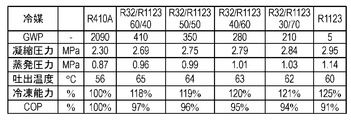
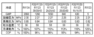
- FIG. 2 shows the pressure, temperature, and compression of the refrigeration cycle at a mixing ratio in which R32 is 30 wt% or more and 60 wt% or less in the mixed working fluid of R1123 and R32 in the first embodiment of the present invention. It is the figure which calculated the refrigerating capacity and cycle efficiency (COP) in case the displacement of a machine is the same, and compared with R410A and R1123.
- COP refrigerating capacity and cycle efficiency
- FIG. 3 shows the pressure, temperature, and compression of the refrigeration cycle at a mixing ratio in which R32 is 30 wt% or more and 60 wt% or less in the mixed working fluid of R1123 and R32 in the first embodiment of the present invention. It is the figure which calculated the refrigerating capacity and cycle efficiency (COP) in case the displacement of a machine is the same, and compared with R410A and R1123.
- FIG. 4 shows the pressure, temperature, and compression of the refrigeration cycle at a mixing ratio in which R125 is 30 wt% or more and 60 wt% or less in the mixed working fluid of R1123 and R125 in the first embodiment of the present invention.
- FIG. 5 shows the pressure, temperature, and compression of the refrigeration cycle in a mixed working fluid of R1123 and R125 in the first embodiment of the present invention at a mixing ratio where R125 is 30 wt% or more and 60 wt% or less. It is the figure which calculated the refrigerating capacity and cycle efficiency (COP) in case the displacement of a machine is the same, and compared with R410A and R1123.
- FIG. 6 shows the refrigeration cycle pressure, temperature, and compressor displacement when the mixing ratio of R32 and R125 is fixed to 50% by weight and mixed with R1123 in the first embodiment of the present invention.
- FIG. 7 shows the refrigeration cycle pressure, temperature, and displacement of the compressor when the mixing ratio of R32 and R125 is fixed to 50% by weight and mixed with R1123 in the first embodiment of the present invention. It is the figure which computed the refrigerating capacity and cycle efficiency (COP) in the case of the same volume, and compared with R410A and R1123.
- FIG. 8 is a longitudinal sectional view of the scroll compressor according to the first embodiment of the present invention.
- FIG. 9 is an enlarged cross-sectional view of a main part of the compression mechanism portion of the scroll compressor according to the first embodiment of the present invention.
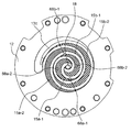
- FIG. 10 is a plan view showing the configuration of the compression chamber of the compression mechanism section of the scroll compressor according to the first embodiment of the present invention.
- FIG. 11 is a diagram for explaining a comparison of pressures in the respective compression chambers in the first embodiment (when a bypass hole is provided) and when it is not provided (comparative example).
- FIG. 12 is a plan view showing the configuration of the compression chamber of the compression mechanism portion of the scroll compressor according to the modification of the first embodiment of the present invention.
- FIG. 13 is a partial cross-sectional view showing a structure in the vicinity of the power supply terminal of the compressor according to the first embodiment of the present invention.
- FIG. 14 is a diagram for explaining the configuration of the refrigeration cycle apparatus according to the second embodiment of the present invention.
- FIG. 15 is a Mollier diagram for explaining the operation of the refrigeration cycle apparatus according to the second embodiment of the present invention.
- FIG. 16 is a Mollier diagram for describing the control operation of Modification 1 of the second embodiment of the present invention.
- FIG. 17 is a Mollier diagram showing the control operation of Modification 2 of the control method of the refrigeration cycle apparatus according to the second embodiment of the present invention.
- FIG. 18 is a diagram illustrating a pipe joint that constitutes a part of the pipe of the refrigeration cycle apparatus according to the second embodiment of this invention.
- FIG. 19 is a diagram showing a configuration of a refrigeration cycle apparatus according to the third embodiment of the present invention.
- FIG. 20 is a diagram showing a configuration of a refrigeration cycle apparatus according to the fourth embodiment of the present invention.
- FIG. 21 is a diagram showing the operation of the refrigeration cycle apparatus according to the fourth embodiment of the present invention on a Mollier diagram.
- FIG. 22 is an enlarged cross-sectional view of a main part of the compression mechanism portion of the scroll compressor according to the fifth embodiment of the present invention.
- FIG. 23 is a system configuration diagram of the refrigeration cycle apparatus using the compressor according to the sixth embodiment of the present invention.
- FIG. 24 shows the pressure, temperature, and compression of the refrigeration cycle in the mixed working fluid of R1123 and R32 in the sixth embodiment of the present invention at a mixing ratio where R32 is 30 wt% or more and 60 wt% or less.
- FIG. 25 shows the pressure, temperature, and compression of the refrigeration cycle in the mixed working fluid of R1123 and R32 in the sixth embodiment of the present invention at a mixing ratio where R32 is 30 wt% or more and 60 wt% or less. It is the figure which calculated the refrigerating capacity and cycle efficiency (COP) in case the displacement of a machine is the same, and compared with R410A and R1123.
- FIG. 25 shows the pressure, temperature, and compression of the refrigeration cycle in the mixed working fluid of R1123 and R32 in the sixth embodiment of the present invention at a mixing ratio where R32 is 30 wt% or more and 60 wt% or less.
- FIG. 26 shows the pressure, temperature, and compression of the refrigeration cycle in a mixed working fluid of R1123 and R125 in the sixth embodiment of the present invention at a mixing ratio where R125 is 30 wt% or more and 60 wt% or less. It is the figure which calculated the refrigerating capacity and cycle efficiency (COP) in case the displacement of a machine is the same, and compared with R410A and R1123.
- FIG. 27 shows the pressure, temperature, and compression of the refrigeration cycle at a mixing ratio in which R125 is 30 wt% or more and 60 wt% or less in the mixed working fluid of R1123 and R125 in the sixth embodiment of the present invention.
- FIG. 28 shows the refrigeration cycle pressure, temperature, and compressor displacement when the mixing ratio of R32 and R125 is fixed at 50% by weight and mixed with R1123 in the sixth embodiment of the present invention. It is the figure which computed the refrigerating capacity and cycle efficiency (COP) in the case of the same volume, and compared with R410A and R1123.
- FIG. 29 shows the refrigeration cycle pressure, temperature, and compressor displacement when the mixing ratio of R32 and R125 is fixed to 50% by weight and mixed with R1123 in the sixth embodiment of the present invention.
- FIG. 30 is a longitudinal sectional view of a scroll compressor according to the sixth embodiment of the present invention.
- FIG. 31 is an enlarged cross-sectional view of a main part of a compression mechanism portion of a scroll compressor according to the sixth embodiment of the present invention.
- FIG. 32 is a diagram showing a state in which the turning scroll is engaged with the fixed scroll according to the sixth embodiment of the present invention.
- FIG. 33 is a diagram showing pressure rise curves of the first compression chamber and the second compression chamber in the sixth embodiment of the present invention.
- FIG. 34 is a diagram showing a state in which the orbiting scroll is engaged with the fixed scroll and viewed from the back of the orbiting scroll in the sixth embodiment of the present invention.
- FIG. 35 is a partial cross-sectional view showing the structure in the vicinity of the power supply terminal of the scroll compressor according to the sixth embodiment of the present invention.
- FIG. 36 is a diagram for explaining the configuration of the refrigeration cycle apparatus according to the seventh embodiment of the present invention.
- FIG. 37 is a Mollier diagram for explaining the operation of the refrigeration cycle apparatus according to the seventh embodiment of the present invention.
- FIG. 38 is a Mollier diagram for describing the control operation of Modification 1 of the seventh embodiment of the present invention.
- FIG. 39 is a Mollier diagram showing the control operation of Modification 2 of the control method of the refrigeration cycle apparatus in the seventh embodiment of the present invention.
- FIG. 40 is a diagram showing a pipe joint that constitutes a part of the pipe of the refrigeration cycle apparatus according to the seventh embodiment of the present invention.
- FIG. 41 is a diagram showing a configuration of a refrigeration cycle apparatus according to the eighth embodiment of the present invention.
- FIG. 42 is a diagram showing a configuration of a refrigeration cycle apparatus according to the ninth embodiment of the present invention.
- FIG. 43 shows the operation of the refrigeration cycle apparatus according to the ninth embodiment of the present invention on a Mollier diagram.
- FIG. 44 is a sectional view of a scroll compressor according to the tenth embodiment of the present invention.
- FIG. 1 is a system configuration diagram of a refrigeration cycle apparatus 100 using a compressor 61 according to a first embodiment of the present invention.
- the refrigeration cycle apparatus 100 is mainly composed of a compressor 61, a condenser 62, a throttle mechanism 63, and an evaporator 64, for example, when a cycle exclusively for cooling is used. . And these apparatuses are connected so that a working fluid (refrigerant) may circulate by piping.
- a working fluid refrigerant
- the refrigerant changes to a liquid by at least one of pressurization and cooling, and changes to a gas by at least one of decompression and heating.
- the compressor 61 is driven by a motor, pressurizes the low-temperature and low-pressure gas refrigerant into the high-temperature and high-pressure gas refrigerant, and conveys it to the condenser 62.
- the condenser 62 the high-temperature and high-pressure gaseous refrigerant is cooled by air blown by a fan or the like and condensed to become a low-temperature and high-pressure liquid refrigerant.
- the liquid refrigerant is depressurized by the throttle mechanism 63, and a part of the liquid refrigerant becomes a low-temperature and low-pressure gas refrigerant, and the rest becomes a low-temperature and low-pressure liquid refrigerant and is conveyed to the evaporator 64.
- the low-temperature and low-pressure liquid refrigerant is heated and evaporated by air blown by a fan or the like, becomes a low-temperature and low-pressure gas refrigerant, and is again sucked into the compressor 61 and pressurized. Such a cycle is repeated.
- coolant flow path of at least any one of the condenser 62 and the evaporator 64 it is desirable that it is an aluminum-made refrigerant pipe containing aluminum or an aluminum alloy.
- a flat tube provided with a plurality of refrigerant flow holes is desirable for decreasing the condensation temperature or increasing the evaporation temperature.
- the working fluid (refrigerant, working refrigerant) sealed in the refrigeration cycle apparatus 100 of the present embodiment is composed of (1) R1123 (1,1,2-trifluoroethylene) and (2) R32 (difluoromethane). It is a two-component mixed working fluid, and in particular, R32 is a mixed working fluid of 30 wt% to 60 wt%.
- the disproportionation reaction of R1123 can be suppressed by mixing R32 with 30 wt% or more of R1123.
- R32 relaxes the disproportionation reaction due to the small polarization to fluorine atoms, and R1123 and R32 have similar physical characteristics, so that behavior during phase change such as condensation and evaporation
- the disproportionation reaction of R1123 can be suppressed by the action of reducing the disproportionation reaction opportunity due to the integration of.
- the mixed refrigerant of R1123 and R32 has an azeotropic boiling point with R32 being 30% by weight and R1123 being 70% by weight, and there is no temperature slip, so that it can be handled in the same manner as a single refrigerant.
- R32 is mixed in an amount of 60% by weight or more, temperature slip increases, and handling similar to that of a single refrigerant may be difficult. Therefore, it is desirable to mix R32 in an amount of 60% by weight or less.
- R32 should be mixed at a ratio of 40 wt% to 50 wt%. Is desirable.
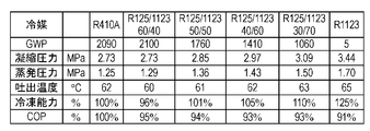
- FIGS. 2 and 3 show the pressure of the refrigeration cycle at a mixing ratio in which R32 is 30 wt% or more and 60 wt% or less of the mixed working fluid of R1123 and R32 in the first embodiment of the present invention, It is the figure which computed the refrigerating capacity in the case of the same temperature, the displacement of a compressor, and cycle efficiency (COP), and compared with R410A and R1123.
- the cooling calculation conditions in Fig. 2 correspond to the cooling operation of the air conditioner (indoor dry bulb temperature 27 ° C, wet bulb temperature 19 ° C, outdoor dry bulb temperature 35 ° C).
- the evaporation temperature was 15 ° C.
- the condensation temperature was 45 ° C.
- the superheated degree of the refrigerant sucked in the compressor was 5 ° C.
- the supercooling degree at the condenser outlet was 8 ° C.
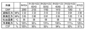
- the heating calculation conditions in FIG. 3 are those corresponding to the heating operation of the air conditioner (indoor dry bulb temperature 20 ° C., outdoor dry bulb temperature 7 ° C., wet bulb temperature 6 ° C.), and the evaporation temperature is 2 ° C.
- the condensation temperature was 38 ° C.
- the superheat degree of the refrigerant sucked into the compressor was 2 ° C.
- the supercool degree at the condenser outlet was 12 ° C.
- a mixture containing R32 in a ratio of 30 wt% to 60 wt% is desirable. More desirably, a mixture containing R32 in a proportion of 40 wt% to 50 wt% is desirable.
- the working fluid sealed in the refrigeration cycle apparatus 100 of the present embodiment is a two-component consisting of (1) R1123 (1,1,2-trifluoroethylene) and (2) R125 (tetrafluoroethane).
- the mixed working fluid may be a mixed working fluid having R125 of 30 wt% or more and 60 wt% or less.
- the disproportionation reaction of R1123 can be suppressed by mixing R125 in an amount of 30% by weight or more.
- the higher the concentration of R125 the more the disproportionation reaction can be suppressed. This is because the disproportionation reaction is mitigated by the small polarization of R125 to fluorine atoms, and the physical properties of R1123 and R125 are similar, so the behavior during phase change such as condensation and evaporation is This is because the disproportionation reaction of R1123 can be suppressed by the action of reducing the disproportionation reaction opportunity by being integrated. Further, since R125 is a nonflammable refrigerant, R125 can reduce the combustibility of R1123.
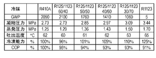
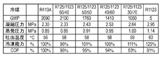
- FIG. 4 and FIG. 5 show the pressure of the refrigeration cycle at a mixing ratio in which R125 is 30 wt% or more and 60 wt% or less of the mixed working fluid of R1123 and R125 in the first embodiment of the present invention, It is the figure which computed the refrigerating capacity in the case of the same temperature, the displacement of a compressor, and cycle efficiency (COP), and compared with R410A and R1123.
- the calculation conditions in FIGS. 4 and 5 are the same as the calculation conditions in FIGS. 2 and 3, respectively.
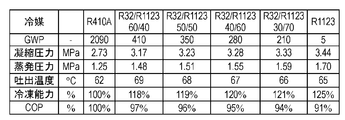
- the refrigerating capacity is 96 to 110% as compared with R410A, and the cycle efficiency (COP) is It turns out that it becomes 94 to 97%.
- R125 at 40 wt% or more and 50 wt% or less, it is possible to prevent disproportionation of R1123 and to reduce the discharge temperature, so that the discharge temperature rises. Equipment design is facilitated. Furthermore, the warming potential can be reduced to 50-100% of R410A.
- the working fluid sealed in the refrigeration cycle apparatus of the present embodiment includes (1) R1123 (1,1,2-trifluoroethylene), (2) R32 (difluoromethane), and (3) R125 (tetra It may be a three-component mixed working fluid made of fluorethane.
- a mixed working fluid in which the mixing ratio of R32 and R125 is 30 to 60% by weight and the mixing ratio of R1123 is 40 to 70% by weight may be used.
- the disproportionation reaction of R1123 can be suppressed by setting the mixing ratio of R32 and R125 to 30% by weight or more. Further, the higher the mixing ratio of R32 and R125, the more the disproportionation reaction can be suppressed. Further, R125 can reduce the combustibility of R1123.
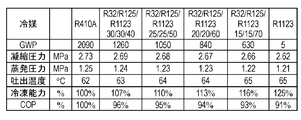
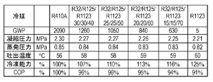
- FIGS. 6 and 7 show the pressure, temperature, and compression of the refrigeration cycle when the mixing ratio of R32 and R125 is fixed to 50% by weight and mixed with R1123 in the first embodiment of the present invention. It is the figure which calculated the refrigerating capacity and cycle efficiency (COP) in case the displacement of a machine is the same, and compared with R410A and R1123.
- the calculation conditions of FIGS. 6 and 7 are the same as the calculation conditions of FIGS. 2 and 3, respectively.
- the refrigerating capacity becomes 107 to 116% as compared with R410A, and the cycle It can be seen that the efficiency (COP) is 93 to 96%.
- the mixing ratio of R32 and R125 is set to 40% by weight or more and 50% by weight or less, disproportionation can be prevented, the discharge temperature can be reduced, and the combustibility can also be reduced. Furthermore, the warming potential can be reduced to 60-30% of R410A.
- the mixing ratio of R32 and R125 of the three-component working fluid has been described as 50 wt%, but the mixing ratio of R32 may be 0 wt% or more and 100 wt% or less.
- the mixing ratio of R32 may be increased.
- the mixing ratio of R32 is decreased and the mixing ratio of R125 is increased, the discharge temperature can be decreased and the combustibility can be decreased.
- R32 and R125 are mixed, and the sum of R32 and R125 is 30 wt% or more and 60 wt% or less.
- the resulting mixture is desirable. More preferably, a mixture containing 40% by weight or more and 50% by weight or less of the sum of R32 and R125 is desirable.
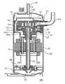
- FIG. 8 is a longitudinal sectional view of the scroll compressor 200 according to the first embodiment of the present invention
- FIG. 9 is an enlarged sectional view of a main part of the compression mechanism unit 2 of the scroll compressor 200
- 10 is a plan view showing the configuration of the compression chamber 15 of the compression mechanism section 2 of the scroll compressor 200. FIG. Hereinafter, the configuration, operation, and action of the scroll compressor 200 will be described.
- the scroll compressor 200 includes a hermetic container 1, and a compression mechanism unit 2, a motor unit 3, and an oil storage unit 20 therein.
- the compression mechanism section 2 includes a main bearing member 11 fixed in the sealed container 1 by welding or shrink fitting, a shaft 4 pivotally supported on the main bearing member 11, and bolts on the main bearing member 11.
- the fixed scroll 12 is provided.
- the compression mechanism portion 2 is configured by sandwiching a turning scroll 13 that engages with the fixed scroll 12 between the main bearing member 11 and the fixed scroll 12.
- a rotation restraining mechanism 14 such as an Oldham ring that guides the orbiting scroll 13 so as to prevent the rotation of the orbiting scroll 13 and move it in a circular orbit.
- the orbiting scroll 13 By turning the orbiting scroll 13 eccentrically by the eccentric shaft portion 4a at the upper end of the shaft 4, the orbiting scroll 13 can be moved in a circular orbit.
- Each of the fixed scroll 12 and the orbiting scroll 13 has a structure in which a spiral wrap rises (projects) from the end plate.
- the compression chamber 15 formed between the fixed scroll 12 and the orbiting scroll 13 moves the working refrigerant from the outer peripheral side toward the center while reducing the volume.
- the working refrigerant is sucked in through the suction pipe 16 connected to the suction pipe 16 and the suction port 17 in the outer peripheral portion of the fixed scroll 12, is closed in the compression chamber 15, and is compressed.
- the working refrigerant that has reached a predetermined pressure is different from the discharge hole 18 on the end plate of the fixed scroll 12 and the discharge hole 18 that is a through hole formed in the center portion (end plate center position) of the fixed scroll 12.
- the reed valve 19 (check valve) is pushed open from the circular bypass hole 68, which is a through hole, formed in the discharge hole 31 and discharged into the discharge chamber 31.
- the discharge chamber 31 is a space formed by a muffler 32 provided so as to cover the discharge hole 18.
- the working refrigerant discharged into the discharge chamber 31 is discharged into the sealed container 1 through the communication path provided in the compression mechanism unit 2.
- the working refrigerant discharged into the sealed container 1 is discharged from the sealed container 1 to the refrigeration cycle apparatus 100 through the discharge pipe 50.
- a valve stop 69 for regulating the lift amount is provided.
- the reed valve 19 is provided, for example, on the end plate surface at the position where the bypass hole 68 of the end plate of the fixed scroll 12 is formed.
- a pump 25 is provided at the other end of the shaft 4, and the suction port of the pump 25 is disposed in the oil storage unit 20. Since the pump 25 is driven simultaneously with the scroll compressor 200, the compressor lubricating oil 6 (oil, refrigerating machine oil) in the oil storage section 20 provided at the bottom of the hermetic container 1 is related to the pressure condition and the operating speed. It can be sucked up reliably, and the worry of running out of oil is also eliminated.
- the compressor lubricating oil 6 sucked up by the pump 25 is supplied to the compression mechanism section 2 through an oil supply hole 26 penetrating the shaft 4 (see FIG. 9).
- the compressor lubricating oil 6 can be prevented from being mixed into the compression mechanism 2 by removing foreign matter with an oil filter or the like before being sucked up by the pump 25 or after being sucked up. It is possible to improve the performance.
- the compressor lubricating oil 6 guided to the compression mechanism unit 2 also serves as a back pressure source for the orbiting scroll 13 having a pressure substantially equal to the discharge pressure of the scroll compressor 200.
- the orbiting scroll 13 does not move away from the fixed scroll 12 or is not biased, and exhibits a predetermined compression function stably.
- a part of the compressor lubricating oil 6 is obtained from the fitting portion between the eccentric shaft portion 4a and the orbiting scroll 13 and the shaft 4 and the main bearing member 11 so as to obtain a clearance by the supply pressure and the own weight. After entering the bearing portion 66 between them and lubricating each portion, it falls and returns to the oil storage portion 20.
- the seal member 78 is partitioned into the high pressure region 30 and the outside of the seal member 78 is divided into the back pressure chamber 29.
- the pressure in the high pressure region 30 and the pressure in the back pressure chamber 29 can be completely separated, the pressure load from the back surface 13e of the orbiting scroll 13 can be stably controlled.
- the compression chamber 15 formed by the fixed scroll 12 and the orbiting scroll 13 includes first compression chambers 15a-1 and 15a-2 formed on the wrap outer wall side of the orbiting scroll 13, and a first compression chamber 15a formed on the wrap inner wall side.
- This configuration in which compression chambers are formed on the outer wall side and the inner wall side of the wrap is referred to as “a configuration in which compression chambers are formed in both directions”.
- the gas sucked into each compression chamber 15 swirls. Along with the turning motion of the scroll 13, it moves to the center while reducing the volume.
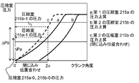
- FIG. 11 shows the compression of the first embodiment of the present invention (when the bypass holes 68a-1, 68a-2, 68b-1, 68b-2 are provided) and when it is not provided (comparative example).
- FIG. 6 is a view for explaining a comparison of pressures in a chamber 15.
- the bypass holes 68a-1, 68a-2, 68b-1, and 68b-2 are provided at positions that communicate with the compression chamber 15 earlier than the discharge holes 18 (at an earlier timing). Yes. As a result, the pressure in the compression chamber 15 reaches the discharge pressure, and at the same time, the discharge into the discharge chamber 31 is started through the bypass holes 68a-1, 68a-2, 68b-1, and 68b-2.
- the structure which can suppress a raise can be implement
- bypass holes 68a-1, 68a-2, 68b-1, 68b-2 circular communication holes, the area of the bypass holes 68a-1, 68a-2, 68b-1, 68b-2 is reduced.
- the flow path resistance can be configured to be the minimum as compared with the case of other shapes.
- the first compression chambers 15a-1, 15a-2 (solid line) and the second compression chambers 15b-1, 15b-2 (broken line) each reach the discharge pressure.
- the crank rotation angle is different. Therefore, in the present embodiment, the bypass holes 68a-1 and 68a-2 communicate only with the first compression chambers 15a-1 and 15a-2, and the bypass holes 68b-1 and 68b-2 are in the second compression chamber.
- FIG. 12 is a plan view showing the configuration of the compression chamber 15 of the compression mechanism unit 2 of the scroll compressor 200 according to the modification of the first embodiment of the present invention.
- the bypass hole 68ab is provided at a position communicating with both the first compression chamber 15a and the second compression chamber 15b by the orbiting motion of the orbiting scroll 13.
- the diameter of the bypass hole 68ab is made smaller than the thickness of the orbiting scroll wrap 13c so as not to open to the first compression chamber 15a and the second compression chamber 15b.
- the bypass hole 68ab-1 communicates with the second compression chamber 15b-1
- the bypass hole 68ab-3 communicates with the first compression chamber 15a-1. It plays a role in preventing over-compression.
- the bypass hole 68ab has the first compression chamber 15a-1 and the second compression chamber 15a-1. It does not communicate with any of the compression chambers 15b-1. Thereby, since the temperature rise can be suppressed without causing working refrigerant leakage between the compression chambers, the disproportionation reaction of R1123 can be suppressed.
- polyol ester oil is used as the compressor lubricating oil.
- the polyol ester of the present invention is not limited to a specific type, at least one selected from the group consisting of neopentyl glycol, trimethylolpropane, pentaerythritol, and dipentaerythritol is used as a constituent alcohol.
- the viscosity of the refrigerating machine oil can be widely adjusted. According to this configuration, since the viscosity of the refrigerating machine oil can be freely adjusted, an oil film between the vane and the piston can be secured, and generation of sliding heat can be suppressed. Further, since the carbonyl group of the polyol ester oil supplements a radical that triggers the disproportionation reaction, the disproportionation reaction of R1123 can be suppressed.
- the constituent fatty acid of the polyol ester of the present invention is not limited to a specific one, but it is optimal to use a fatty acid having 6 to 12 carbon atoms.
- the constituent fatty acid may be a straight-chain fatty acid or a branched-chain fatty acid, but the straight-chain fatty acid has the ability to trap radicals because the carbonyl group is not sterically shielded by an alkyl group. high.
- an antiwear agent As an additive added to the lubricating oil 6 for a compressor, an antiwear agent, an antioxidant, a polymerization inhibitor, a reactant adsorbent, and the like can be used.
- Antiwear agents include phosphate ester, phosphite, thiophosphate, and the like, but phosphate esters that do not adversely affect the refrigeration cycle apparatus are optimal.
- phosphate esters include tributyl phosphate, tripentyl phosphate, trihexyl phosphate, triheptyl phosphate, trioctyl phosphate, trinonyl phosphate, tridecyl phosphate, triundecyl phosphate, tridodecyl phosphate, tritridecyl phosphate.
- Tritetradecyl phosphate tripentadecyl phosphate, trihexadecyl phosphate, triheptadecyl phosphate, trioctadecyl phosphate, trioleyl phosphate, triphenyl phosphate, tricresyl phosphate, trixylenyl phosphate, cresyl diphenyl phosphate, and Examples include xylenyl diphenyl phosphate.
- phosphate ester-based antiwear agent is added to the refrigerating machine oil in an amount of 0.1 to 3 wt%, so that it is efficiently adsorbed on the surface of the sliding part and creates a film with a small shearing force on the sliding surface. Thus, an anti-wear effect can be obtained.
- the wear preventive agent is adsorbed on the surface of the sliding portion to reduce friction, so that heat generation can be suppressed and the self-decomposition reaction of the R1123 refrigerant can be suppressed.
- phenolic antioxidants include propyl gallate, 2,4,5-trihydroxybutyrophenone, t-butylhydroquinone, nordihydroguaiaretic acid, butylhydroxyanisole, 4-hydroxymethyl-2, 6-di-t-butylphenol, octyl gallate, butylhydroxytoluene, dodecyl gallate and the like can be used.
- phenolic antioxidants include propyl gallate, 2,4,5-trihydroxybutyrophenone, t-butylhydroquinone, nordihydroguaiaretic acid, butylhydroxyanisole, 4-hydroxymethyl-2, 6-di-t-butylphenol, octyl gallate, butylhydroxytoluene, dodecyl gallate and the like can be used.
- radicals can be efficiently captured and reaction can be prevented. It is also possible to minimize the coloring of the base oil itself by the antioxidant.
- the phenol-based antioxidant can effectively capture the radicals generated in the sealed container 1, thereby obtaining an effect of suppressing the decomposition reaction of R1123.
- the scroll compressor 200 of the present embodiment and the refrigeration cycle apparatus 100 using the scroll compressor 200 are closed systems, and lubricating oil is sealed as a base oil as described above.
- the viscosity of the lubricating oil that is the base oil enclosed in the scroll compressor 200 is generally about 32 mm 2 / s to 68 mm 2 / s, while the viscosity of limonene is about 0.2 mm. The viscosity is considerably low at about 8 mm 2 / s.
- the viscosity of the lubricating oil is 60 mm 2 / s when limonene is mixed about 5%, 48 mm 2 / s when 15% is mixed, and 32 mm 2 / s when 35% is mixed. Go down. Therefore, when a large amount of limonene is mixed in an attempt to prevent the reaction of R1123, the scroll compressor 200 and the refrigeration compressor 200 and the refrigeration are caused by a decrease in the viscosity of the lubricating oil, wear due to poor lubrication, and generation of metal soap due to metal contact with the sliding surface. The reliability of the cycle device 100 is affected.
- the lubricating oil of the scroll compressor 200 of the present embodiment is preliminarily provided with a high-viscosity lubricating oil in order to compensate for the decrease in the viscosity of the base oil caused by mixing the limonene in an amount suitable for preventing reaction.
- a proper lubricating oil viscosity is ensured by using a base or mixing an ultra-high viscosity lubricating oil in an amount equal to or greater than the amount of limonene.
- the viscosity of the lubricating oil when mixing 5% limonene is 78 mm 2 / s
- the viscosity of the lubricating oil when mixing 35% limonene is about 230 mm 2 / s.
- a viscosity of 68 mm 2 / s can be secured.
- extreme examples such as increasing the amount of limonene mixed to 70% or 80% are also conceivable.
- the viscosity of the lubricating oil of high viscosity as the base each becomes a 8500 mm 2 / s or 25000 mm 2 / s, exceeds 3200 mm 2 / s which is the maximum value of the ISO standard.
- uniform mixing with limonene becomes difficult, practical application is considered difficult.
- a viscosity of 32 mm 2 / s to 68 mm 2 / s can be obtained by mixing lubricating oil of 800 mm 2 / s to 1000 mm 2 / s.
- a lubricating oil having a relatively uniform composition viscosity can be obtained by adding the ultra-high viscosity oil to limonene while adding small amounts.
- limonene is used as an example, but the same effect can be obtained with terpenes or terpenoids.
- hemiterpenes isoprene, prenol, 3-methylbutanoic acid and monoterpenes geranyl diphosphate, cineol, pinene and sesquiterpenes farnesyl diphosphate, artemisinin, bisabolol, diterpenes geranylgeranyl diphosphate, retinol, Retinal, phytol, paclitaxel, forskolin, aphidicolin and triterpene squalene, and lanosterol can be selected according to the operating temperature of the scroll compressor 200 and the refrigeration cycle apparatus 100 and the required lubricating oil viscosity.
- the illustrated viscosity is a specific example in the scroll compressor 200 having a high-pressure vessel, but a low-pressure vessel in which a relatively low viscosity lubricating oil of 5 mm 2 / s to 32 mm 2 / s is used.
- a relatively low viscosity lubricating oil of 5 mm 2 / s to 32 mm 2 / s is used. The same effect can be obtained with the scroll compressor 200 having the same effect.
- terpenes and terpenoids such as limonene have solubility in plastics, but if they are mixed at about 30% or less, the influence is slight, and the electric power required for plastics in the scroll compressor 200 is small. It is not at a level where insulation is a problem. However, when long-term reliability is required, and when there is a problem such as when the operating temperature is always high, it is desirable to use polyimide, polyimide amide, or polyphenylene sulfide having chemical resistance. .
- varnish is applied and baked on the conductor via an insulating coating on the winding of the motor unit 3 of the scroll compressor 200 of the present embodiment.
- thermosetting insulating material include a polyimide resin, an epoxy resin, and an unsaturated polyester resin.
- the polyimide resin can be converted into a polyimide by coating in the state of polyamic acid as a precursor and baking at around 300 ° C. It is known that the imidization reaction occurs by a reaction between an amine and a carboxylic acid anhydride.
- the R1123 refrigerant may react even in a short circuit between the electrodes, on the motor winding (mainly a polyimide precursor formed by reacting an aromatic diamine and an aromatic tetracarboxylic dianhydride)
- a short circuit between the electrodes By applying the polyimide acid varnish, a short circuit between the electrodes can be prevented.
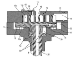
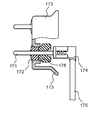
- FIG. 13 is a partial cross-sectional view showing the structure in the vicinity of the power supply terminal of the scroll compressor 200 according to the first embodiment of the present invention.
- a donut-shaped insulating member 76 that is in close contact with the glass insulator 72 that is an insulating member is disposed on the power supply terminal 71 inside the sealed container 1 of the scroll compressor 200. It is touched.
- the donut-shaped insulating member 76 maintains the insulating property, and is optimally resistant to hydrofluoric acid. Examples thereof include ceramic insulators and HNBR rubber donut spacers. It is essential that the doughnut-shaped insulating member 76 is in close contact with the glass insulator 72, but it is preferable that the donut-like insulating member 76 is also in close contact with the connection terminal.
- the power supply terminal 71 configured in this manner has a long creepage distance between the power supply terminal and the inner surface of the scroll compressor 200 due to the donut-shaped insulating member 76, prevents terminal tracking, and discharge energy of R1123. Can prevent ignition. Further, it is possible to prevent the hydrofluoric acid generated by the decomposition of R1123 from corroding the glass insulator 72.
- the scroll compressor 200 may be a so-called high pressure shell type compressor in which the discharge port is opened in the sealed container 1 and the sealed container 1 is filled with the refrigerant compressed in the compression chamber 15. .
- a so-called low-pressure shell type scroll compressor 200 in which the suction port 17 is opened in the sealed container 1 and the inside of the sealed container 1 is filled with the refrigerant before being compressed in the compression chamber 15 may be used.
- the temperature reduction due to the introduction of the low-temperature refrigerant in the compression chamber 15 becomes more prominent. It is desirable to suppress the disproportionation reaction.
- the refrigerant discharged from the discharge port is passed around the motor unit 3 and heated by the motor unit 3 in the sealed container 1, and then the sealed container is discharged from the discharge pipe 50. 1 may be configured to be discharged to the outside. According to this configuration, even if the temperature of the refrigerant discharged from the discharge pipe 50 is equal, the refrigerant temperature in the compression chamber 15 can be lowered, which is desirable in suppressing the disproportionation reaction of R1123.
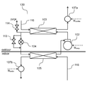
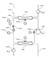
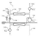
- FIG. 14 is a diagram for explaining the configuration of the refrigeration cycle apparatus 101 according to the second embodiment of the present invention.
- a compressor 102, a condenser 103, an expansion valve 104 that is a throttling mechanism, and an evaporator 105 are connected in this order through a refrigerant pipe 106 to constitute a refrigeration cycle circuit.
- a working fluid (refrigerant) is enclosed in the refrigeration cycle circuit.
- a fin-and-tube heat exchanger As the condenser 103 and the evaporator 105, when the surrounding medium is air, a fin-and-tube heat exchanger, a parallel flow type (microtube type) heat exchanger, or the like is used.
- the condenser 103 and the evaporator 105 when the surrounding medium is brine or a refrigerant of a binary refrigeration cycle apparatus a double tube heat exchanger, a plate heat exchanger, or shell and tube heat is used. An exchanger is used.
- expansion valve 104 for example, a pulse motor drive type electronic expansion valve or the like is used.
- a fluid machine 107 a that is a first transport unit that drives (flows) an ambient medium (first medium) that exchanges heat with a refrigerant to a heat exchange surface of the condenser 103.
- the evaporator 105 is provided with a fluid machine 107b that is a second transport unit that drives (flows) an ambient medium (second medium) that exchanges heat with the refrigerant to the heat exchange surface of the evaporator 105.
- a flow path 116 for the surrounding medium is provided for each surrounding medium.
- the refrigeration cycle apparatus 101 is a binary refrigeration cycle apparatus, a refrigerant that is preferable for the refrigeration cycle circuit and the operating temperature range, such as hydrofluorocarbon (HFC), hydrocarbon (HC), or carbon dioxide, is used. .
- HFC hydrofluorocarbon
- HC hydrocarbon
- carbon dioxide carbon dioxide
- the fluid machines 107a and 107b for driving the surrounding medium when the surrounding medium is air, an axial blower such as a propeller fan, a cross flow blower, or a centrifugal blower such as a turbo blower is used, and the surrounding medium is brine.
- a centrifugal pump or the like is used.
- the compressor 102 serves as the fluid machines 107a and 107b for transporting the surrounding medium.
- a condensing temperature detecting unit is provided at a location where the refrigerant flowing in the inside of the condenser 103 flows in two phases (a state where gas and liquid are mixed) (hereinafter referred to as “two-phase tube of the condenser”). 110a is installed, and the refrigerant temperature can be measured.
- a condenser outlet temperature detector 110b is installed between the outlet of the condenser 103 and the inlet of the expansion valve 104.
- the condenser outlet temperature detector 110b can detect the degree of supercooling at the inlet of the expansion valve 104 (a value obtained by subtracting the temperature of the condenser 103 from the inlet temperature of the expansion valve 104).
- an evaporation temperature detection unit 110 c is provided at a portion where the refrigerant flowing in the evaporator flows in two phases (hereinafter referred to as “two-phase pipe of the evaporator” in this specification). It is possible to measure the temperature of the refrigerant.
- a suction temperature detector 110d is provided in the suction part of the compressor 102 (between the outlet of the evaporator 105 and the inlet of the compressor 102). As a result, the temperature of the refrigerant sucked into the compressor 102 (intake temperature) can be measured.
- an electronic thermostat that is contact-connected with a pipe through which a refrigerant flows or an outer pipe of a heat transfer pipe may be used, or a sheath pipe system that directly contacts the working fluid. In some cases, an electronic thermostat is used.
- a high pressure side pressure detector 115a is installed.
- a low-pressure side pressure detector 115b that detects the pressure on the low-pressure side of the refrigeration cycle circuit (region where the refrigerant from the outlet of the expansion valve 104 to the inlet of the compressor 102 exists at low pressure) is installed. ing.
- the high-pressure side pressure detection unit 115a and the low-pressure side pressure detection unit 115b for example, a device that converts the displacement of the diaphragm into an electrical signal is used.
- a differential pressure gauge (measuring means for measuring the pressure difference at the inlet / outlet of the expansion valve 104) may be used instead of the high pressure side pressure detector 115a and the low pressure side pressure detector 115b.
- the refrigeration cycle apparatus 101 is described as including all the temperature detection units and each pressure detection unit. However, a detection unit that does not use a detection value in the control described later. Can be omitted.
- the degree of superheat of the working fluid at the suction portion of the compressor 102 which is the temperature difference between the suction temperature detection portion 110d and the evaporation temperature detection portion 110c, is calculated. Then, the expansion valve 104 is controlled so that this superheat degree becomes a predetermined target superheat degree (for example, 5K).
- a discharge temperature detection unit (not shown) in the discharge unit of the compressor 102 and perform control using the detected value.
- the degree of superheat of the working fluid at the discharge part of the compressor 102 which is the temperature difference between the discharge temperature detection part and the condensation temperature detection part 110a, is calculated.
- the expansion valve 104 is controlled so that this superheat degree becomes a predetermined target superheat degree.
- control is performed to open the expansion valve 104 and reduce the pressure and temperature of the high-pressure side working fluid in the refrigeration cycle apparatus 101. Is called.
- the temperature at the critical point (critical temperature) is taken as a guide, and the expansion valve is kept from approaching the temperature within a predetermined value (5 K) from this temperature.
- the opening degree of 104 is controlled.
- the critical temperature of the mixed refrigerant is used to control the temperature of the working fluid so that it does not become (critical temperature ⁇ 5 ° C.) or higher.
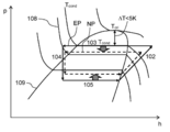
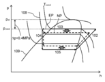
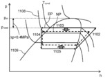
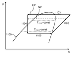
- FIG. 15 is a Mollier diagram for explaining the operation of the refrigeration cycle apparatus 101 according to the second embodiment of the present invention.
- FIG. 15 shows an isotherm 108 and a saturated liquid / saturated vapor line 109.
- a refrigeration cycle under an excessive pressure condition that causes a disproportionation reaction is indicated by a solid line (EP), and a refrigeration cycle under normal operation is indicated by a broken line (NP).
- the control is performed.
- the device controls the opening of the expansion valve 104 to the opening side.
- the condensing pressure on the high-pressure side of the refrigeration cycle apparatus 101 decreases as shown by NP in FIG. 15, so that it becomes possible to suppress the disproportionation reaction caused by excessive increase in the refrigerant pressure. Even when the leveling reaction occurs, the pressure rise can be suppressed.
- the above-described control method is a method of indirectly grasping the pressure in the condenser 103 from the condensation temperature measured by the condensation temperature detection unit 110a and controlling the opening degree of the expansion valve 104.
- the working fluid containing R1123 is azeotropic or pseudoazeotropic, and there is no or small temperature difference (temperature gradient) between the dew point and boiling point of the working fluid containing R1123 in the condenser 103.
- the condensation temperature can be used as an index instead of the condensation pressure, which is particularly preferable.
- ⁇ Modification 1 of Control Method> As described above, by comparing the critical temperature and the condensation temperature, the state of high pressure (refrigerant pressure in the condenser 103) of the refrigeration cycle apparatus 101 is indirectly detected, and an appropriate operation is performed on the expansion valve. Instead of the control method instructing 104 or the like, a method of controlling the opening degree of the expansion valve 104 based on the directly measured pressure may be used.
- FIG. 16 is a Mollier diagram for explaining the control operation of the first modification of the second embodiment of the present invention.
- FIG. 16 a refrigeration cycle in which an excessive pressure rise is occurring from the discharge portion of the compressor 102 to the inlets of the condenser 103 and the expansion valve 104 is indicated by a solid line (EP) and indicated by a broken line (NP) as described above.
- the refrigeration cycle in a state of being released from the excessive pressure state is shown.
- the working fluid including R1123 is changed from the discharge port of the compressor 102 to the inlet of the expansion valve 104. Therefore, it is determined that the disproportionation reaction has occurred or is likely to occur, and the opening of the expansion valve 104 is controlled so as to avoid the sustaining under the high pressure condition.
- the refrigeration cycle in FIG. 16 acts on the side where the high pressure (condensation pressure) decreases, as indicated by NP in the figure, and causes the disproportionation reaction or after the disproportionation reaction.
- the pressure rise which arises can be suppressed.
- This control method is preferably used when the working fluid including R1123 is in a non-azeotropic state, particularly when the temperature gradient is large at the condensation pressure.
- ⁇ Modification 2 of control method> Note that a control method based on the degree of supercooling may be used instead of the control method based on the critical temperature or critical pressure described above.
- FIG. 17 is a Mollier diagram showing the control operation of the second modification of the control method of the refrigeration cycle apparatus 101 in the second embodiment of the present invention.
- the temperature of the refrigerant in the condenser 103 is changed to the surrounding medium by appropriate control of the refrigeration cycle, the heat exchanger size, and the refrigerant charge amount optimization such as the expansion valve 104 and the compressor 102.
- the temperature is set to be higher to a certain extent.
- the degree of supercooling generally takes a value of about 5K. Similar measures are taken for the working fluid including R1123 used in the same refrigeration cycle apparatus 101.
- the opening degree of the expansion valve 104 is controlled based on the degree of supercooling of the refrigerant at the inlet of the expansion valve 104.
- the degree of supercooling of the refrigerant at the inlet of the expansion valve 104 during normal operation is assumed to be 5K, and the opening degree of the expansion valve 104 is controlled using 15K, which is three times the value as a guide. I have decided.
- the reason why the degree of supercooling as the threshold is tripled is that the degree of supercooling may change within that range depending on the operating conditions.
- the degree of supercooling is calculated from the detection value of the condensation temperature detection unit 110a and the detection value of the condenser outlet temperature detection unit 110b.
- the degree of supercooling is a value obtained by subtracting the detection value of the condenser outlet temperature detection unit 110b from the detection value of the condensation temperature detection unit 110a.
- the degree of supercooling at the inlet of the expansion valve 104 reaches a predetermined value (15K)
- the expansion valve 104 is operated to open the opening, and the condensation pressure that is the high-pressure portion of the refrigeration cycle apparatus 101 is operated. Is controlled in the direction of lowering (broken line to broken line in FIG. 17).
- the condensing pressure is decreased, because the condensation temperature is equivalent to decrease, it decreases from condensation temperature T cond 1 to T cond2, supercooling degree of the expansion valve 104 inlet, the T cond 1 -T EXIN, The degree of supercooling decreases to T cond2 ⁇ T exin (here, it is assumed that the working fluid temperature at the inlet of the expansion valve 104 does not change but is T exin ). As described above, the degree of supercooling decreases as the condensing pressure in the refrigeration cycle apparatus 101 decreases, so that the condensing pressure in the refrigeration cycle apparatus 101 can be controlled even when the degree of supercooling is used as a reference. I understand.
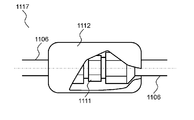
- FIG. 18 is a view showing a pipe joint 117 constituting a part of the pipe of the refrigeration cycle apparatus 101 according to the second embodiment of the present invention.
- the refrigeration cycle apparatus 101 of the present invention When the refrigeration cycle apparatus 101 of the present invention is used in, for example, a home-use split-type air conditioner (air conditioner), the refrigeration cycle apparatus 101 includes an outdoor unit having an outdoor heat exchanger and an indoor heat exchanger. And an indoor unit. The outdoor unit and the indoor unit cannot be integrated due to the configuration. Therefore, the outdoor unit and the indoor unit are connected at the installation location using a mechanical joint such as the union flare 111 shown in FIG.
- a mechanical joint such as the union flare 111 shown in FIG.
- connection state of the mechanical joint is deteriorated due to causes such as omission of work, the refrigerant leaks from the joint part, which adversely affects the equipment performance.
- the working fluid itself including R1123 is a greenhouse gas having a warming effect, there is a possibility of adversely affecting the global environment. Therefore, it is required to quickly detect and repair the refrigerant leakage.
- the refrigerant leak detection method includes a method of applying a detection agent to the site and detecting whether or not a bubble is generated, and a method of using a detection sensor. large.
- a seal 112 containing a polymerization accelerator is wound around the outer periphery of the union flare 111 to facilitate detection of refrigerant leakage and to reduce the amount of leakage.
- polytetrafluoroethylene which is one of fluorinated carbon resins
- the working fluid containing R1123 and the polymerization accelerator are intentionally brought into contact with each other at a leaking location, and polytetrafluoroethylene is precipitated and solidified at the leaking location.
- the generation site of polytetrafluoroethylene is the leakage site of the working fluid containing R1123, the polymerization product is naturally generated and adhered to the site that prevents the leakage, so it is also possible to reduce the amount of leakage. It becomes.
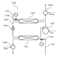
- FIG. 19 is a diagram showing a configuration of a refrigeration cycle apparatus 130 according to the third embodiment of the present invention.
- the difference in configuration between the refrigeration cycle apparatus 130 shown in FIG. 19 and the refrigeration cycle apparatus 101 of the second embodiment is newly connected to the inlet and outlet of the expansion valve 104 and a bypass pipe having an on-off valve. 113 is installed.
- a purge line having a relief valve 114 is provided between the outlet of the condenser 103 and the inlet of the expansion valve 104.
- the opening side of the relief valve 114 is arranged outside the room.
- the control method described in the second embodiment for example, an expansion valve so that the value obtained by subtracting the working fluid temperature measured by the two-phase pipe of the condenser 103 from the critical temperature of the working fluid including R1123 becomes 5K or more.
- 104 and a control method for controlling the difference between the critical pressure of the working fluid and the pressure detected by the high-pressure side pressure detector 115a to be 0.4 MPa or more. Even when the opening degree of the valve 104 is opened, there is a possibility that there is no improvement in the pressure drop, or a situation where the pressure drop speed is desired to be increased.
- the operating fluid pressure on the high pressure side is rapidly increased by opening the on-off valve provided in the bypass pipe 113 of the present embodiment and allowing the refrigerant to flow through the bypass pipe 113. It is possible to suppress the breakage of the refrigeration cycle apparatus 130.
- the refrigeration cycle apparatus 130 can be prevented from being damaged if the compressor 102 is emergency stopped. More preferred above. In the case of emergency stop of the compressor 102, it is desirable not to stop the fluid machines 107a and 107b in order to rapidly reduce the working fluid pressure on the high pressure side.
- the difference between the critical temperature of the working fluid and the condensation temperature detected by the condensation temperature detector 110a is less than 5K. Or a case where the difference between the critical pressure of the working fluid and the pressure detected by the high pressure side pressure detector 115a is less than 0.4 MPa. In such a case, since the refrigerant pressure in the refrigeration cycle apparatus 130 may further increase, it becomes necessary to escape the high-pressure refrigerant to the outside and prevent the refrigeration cycle apparatus 130 from being damaged. Therefore, control is performed to open the relief valve 114 that purges the working fluid including R1123 in the refrigeration cycle apparatus 130 to the external space.
- the installation position of the relief valve 114 in the refrigeration cycle apparatus 130 is preferably on the high pressure side. Further, from the outlet of the condenser 103 shown in the present embodiment to the inlet of the expansion valve 104 (at this position, since the working fluid is in a high-pressure supercooled liquid state, a steep pressure increase associated with the disproportionation reaction occurs. The resulting water hammer effect is likely to occur), or from the discharge part of the compressor 102 to the inlet of the condenser 103 (at this position, the working fluid exists in a gas state of high temperature and high pressure, so the molecular motion becomes active. It is particularly preferable to install it over a point where the disproportionation reaction itself is likely to occur.
- the relief valve 114 is provided on the outdoor unit side.
- the working fluid is not released to the indoor display space, and if it is a refrigeration unit, the working fluid is not released to the product display side such as a showcase. Therefore, it can be said that it is a form that is considered so as not to directly affect humans and commercial materials.
- FIG. 20 is a diagram showing a configuration of a refrigeration cycle apparatus 140 according to the fourth embodiment of the present invention.
- the difference in configuration between the refrigeration cycle apparatus 140 shown in FIG. 20 and the refrigeration cycle apparatus 101 of the second embodiment is that the first medium detects the temperature of the first medium before flowing into the condenser 103.
- a temperature detection unit 110e and a second medium temperature detection unit 110f that detects the temperature of the second medium before flowing into the evaporator 105 are provided. Further, the detected values of each temperature detection unit and each pressure detection unit, and the input power of the compressor 102 and the fluid machines 107a and 107b are recorded in an electronic recording device (not shown) for a certain period of time. Is also different.
- FIG. 21 is a diagram showing the operation of the refrigeration cycle apparatus 140 according to the fourth embodiment of the present invention on a Mollier diagram.
- the refrigeration cycle indicated by EP indicates the condensation pressure when the disproportionation reaction occurs
- the refrigeration cycle indicated by NP indicates the refrigeration cycle during normal operation.
- the cycle change at the time when the condensation pressure rises eg, the difference in evaporation pressure between NP and EP, etc. is not shown in order to simplify the explanation.
- the causes of the sudden rise in the condensation temperature of the working fluid including R1123, measured by the two-phase tube in the condenser 103, are (1) a sudden rise in ambient medium temperatures T mcon and T meva , and (2) compression.
- the pressurizing action due to the power increase of the machine 102, and (3) the flow change of the surrounding medium (the power increase of any of the fluid machines 107a and 107b driving the surrounding medium) can be considered.
- a pressurizing action by a disproportionation reaction can be mentioned as an event specific to the working fluid including R1123. Therefore, in this embodiment, in order to specify that the disproportionation reaction of (4) has occurred, it is determined and controlled that the events from (1) to (3) have not occurred.
- the expansion valve 104 when the change amount of the condensing temperature of the working fluid including R1123 is larger than the change amount of the temperature or input power of (1) to (3), the expansion valve 104 is used. Control to open side.
- control since it is difficult to compare the amount of change in temperature with the amount of change in input power value under the same standard, when measuring the amount of change in temperature, control is performed so that the input power does not change. That is, when measuring the amount of temperature change, the motor speeds of the compressor 102 and the fluid machines 107a and 107b are kept constant.
- the temperature change amount is measured at a certain time interval, for example, for 10 seconds to 1 minute. Prior to this measurement, for example, about 10 seconds to 1 minute before, control is performed so that the input electric energy of the compressor 102 and the fluid machines 107a and 107b is kept at a constant value. At this time, the amount of change per unit time of the input electric energy of the compressor 102 and the fluid machines 107a and 107b is substantially zero.
- “substantially” zero is defined as the change in the suction state of the compressor 102 due to the refrigerant bias in the compressor 102, or the first medium and the second medium in the fluid machines 107a and 107b are ambient air. This is because in some cases, the input power slightly fluctuates due to the influence of wind blowing or the like. That is, “substantially zero” means that it includes a slight fluctuation and is smaller than a predetermined value.
- the amount of change per unit time of the condensation temperature measured by the condensation temperature detection unit 110a per unit time of the temperature of the first medium detected by the first medium temperature detection unit 110e If the amount of change is greater than either the amount of change per unit time of the temperature of the second medium detected by the second medium temperature detector 110f, it is considered that a disproportionation reaction has occurred,
- the expansion valve 104 is controlled in the opening direction.
- a bypass is provided in parallel with the expansion valve 104, as shown in the third embodiment, in case the pressure increase caused by the disproportionation reaction cannot be controlled.
- a pipe 113 may be provided, the compressor 102 may be stopped urgently, and further, a means such as a relief valve 114 for reducing the pressure by discharging the refrigerant to the outside may be provided.
- control example of the expansion valve 104 that performs control based on the amount of change of the temperature detection unit installed in the two-phase pipe of the condenser 103 has been shown.
- the amount of change in pressure at any point from the section to the inlet of the expansion valve 104 may be used as a reference, or the amount of change in the degree of supercooling at the inlet of the expansion valve 104 may be used as a reference.
- FIG. 22 is an enlarged cross-sectional view of a main part of the compression mechanism unit 2 of the scroll compressor 200 according to the fifth embodiment of the present invention.
- the configuration is the same as that of the first embodiment, and thus the description of other configurations is omitted.
- the discharge valve 18 is also provided with the reed valve 19 (check valve).
- the discharge hole 18 has a reed valve. 19 is not provided.
- the discharge chamber 31 is always in communication with the nearby compression chamber 15 through the discharge hole 18, and the discharge chamber 31 and the compression chamber 15 are in a substantially equal pressure state.
- the valve stop 69 is not provided.
- Conditions where the disproportionation reaction is particularly likely to occur are conditions under excessively high temperatures and pressures, so that the conditions are not under predetermined operating conditions, for example, clogging of refrigerant piping in the refrigeration cycle circuit, stop of ventilation of the condenser,
- the compression mechanism removes the refrigerant. There may be a case where the compression work for boosting is not performed.
- the compression mechanism continues to supply power to the electric motor without performing the pressure increasing operation, the pressure increase in the high-pressure side of the refrigeration cycle circuit, that is, the sealed container 1 that houses the electric motor is suppressed.
- the conditions for generating the disproportionation reaction are avoided by pressure.
- the discharge chamber 31 is always in communication with the nearby compression chamber 15 through the discharge hole 18.
- the electric motor when electric power is supplied to the electric motor without the compression mechanism performing the compression operation, the electric motor heats the refrigerant inside the sealed container 1 as a heating element.
- the pressure acts on the compression chamber 15 via the discharge hole 18, and the pressure in the sealed container 1 is rotated to the low pressure side of the refrigeration cycle circuit by rotating the compression mechanism in the reverse direction. Therefore, it is possible to avoid an abnormal pressure increase that is a condition for generating a disproportionation reaction.
- the first aspect shown in the first to fifth embodiments of the present invention uses a refrigerant containing 1,1,2-trifluoroethylene as a working fluid
- a compression chamber is provided that is formed in both directions by using a polyol ester oil as a lubricating oil for a compressor and meshing with a fixed scroll and a turning scroll in which a spiral wrap rises from an end plate.
- the fixed scroll end plate is provided with a discharge hole that opens to the discharge chamber, and a bypass hole is provided in the end plate of the fixed scroll before the compression chamber communicates with the discharge hole.
- the bypass hole is provided with a check valve that allows flow from the compression chamber side to the discharge chamber side.
- the temperature increase due to overcompression of the refrigerant immediately before being ejected from the discharge hole can be suppressed, so that the disproportionation reaction of R1123 can be suppressed.
- the carbonyl group of the polyol ester oil supplements a radical that triggers the disproportionation reaction, the disproportionation reaction of R1123 can be suppressed.
- bypass holes may be provided.
- the section in which the bypass hole and the compression chamber communicate with each other becomes wider, and the individual flow path resistance can be reduced by the total of the flow path areas of the bypass holes that are effective at the same time. An effect of reliably suppressing a temperature rise due to compression can be obtained.
- At least one of the bypass holes may be a circular communication hole.
- At least one of the bypass holes is provided in either the first compression chamber formed on the wrap outer wall side of the orbiting scroll or the second compression chamber formed on the wrap inner wall side of the orbiting scroll. You may provide in the position which only opens.
- each compression chamber can reach the discharge pressure and open the check valve of the bypass hole, and the bypass hole can be provided at an optimal position, and an effect of suppressing the temperature rise due to overcompression can be obtained to the minimum. Can do.
- bypass holes is open to both the first compression chamber formed on the wrap outer wall side of the orbiting scroll and the second compression chamber formed on the wrap inner wall side of the orbiting scroll.
- the bypass hole may have a shape and a size that do not open simultaneously to the first and second compression chambers.
- the first compression chamber and the second compression chamber communicate with each other through the bypass hole, and the working refrigerant is prevented from re-expanding due to the pressure difference to cause a temperature rise in the compression chamber. Can do.
- At least one of the bypass holes may have a configuration in which D / L is in the range of 2.4 to 7.2, where D is the diameter of the bypass hole and L is the length in the end plate thickness direction. Good.
- the second aspect may be configured such that, in the first aspect, the check valve is a reed valve provided on the end plate surface of the fixed scroll.
- the third aspect is the first aspect or the second aspect, wherein the working fluid is a mixed working fluid containing difluoromethane, and the difluoromethane may be 30 wt% or more and 60 wt% or less. Good. Moreover, it is a mixed working fluid containing tetrafluoroethane, and tetrafluoroethane may be 30 wt% or more and 60 wt% or less.
- it is a mixed working fluid containing difluoromethane and tetrafluoroethane, wherein difluoromethane and tetrafluoroethane are mixed, and the mixing ratio of difluoromethane and tetrafluoroethane is 30 wt% or more and 60 wt% or less. There may be.
- the disproportionation reaction of R1123 can be suppressed, and the refrigerating capacity and COP can be improved.
- the polyol ester oil is at least selected from the group consisting of neopentyl glycol, trimethylolpropane, pentaerythritol, and dipentaerythritol.
- One type may be a constituent alcohol.
- the polyol ester oil may contain a phosphate ester antiwear agent.
- the antiwear agent is adsorbed on the surface of the sliding portion to reduce friction, thereby suppressing heat generation and suppressing the self-decomposing reaction of the R1123 refrigerant.
- the polyol ester oil may contain a phenol-based antioxidant.
- the phenolic antioxidant quickly captures radicals generated at the sliding portion, it is possible to prevent the radicals from reacting with the refrigerant R1123.
- the polyol ester oil is a terpene or terpenoid having a viscosity of 1% or more and less than 50%, and a lubricating oil having a higher viscosity than the base oil. Or mixed with pre-mixed ultra-high viscosity lubricating oil equal to or higher than terpenes or terpenoids and adjusted to the same viscosity as the base oil. Good.
- An eighth aspect includes, in any one of the first to third aspects, a motor unit that drives the orbiting scroll, and the motor unit includes a thermosetting insulating material on the conductor with an insulating film interposed therebetween.
- An electric wire formed by coating and baking may be used for the coil.
- thermosetting insulating material to the winding of the motor coil in the compressor, the resistance between the windings remains high even when the coil is immersed in the liquid refrigerant, and the discharge is suppressed. As a result, decomposition of the R1123 refrigerant can be suppressed.
- a ninth aspect includes, in any one of the first to third aspects, a sealed container that houses the compression chamber and the motor unit, and the sealed container is installed in the mouth portion via an insulating member. And a connection terminal for connecting the power supply terminal to the lead wire. And the doughnut-shaped insulating member closely_contact
- an insulator is added to the power supply terminal inside the metal casing, it is possible to suppress the insulation failure of the power supply terminal by extending the shortest distance between the conductors, and to prevent ignition by the discharge energy of R1123. Can be prevented. Further, hydrogen fluoride generated when R1123 is decomposed can be prevented from coming into contact with the glass insulator, and the glass insulator can be prevented from being corroded and broken.
- the compressor according to any one of the first to ninth aspects, a condenser for cooling the refrigerant gas compressed by the compressor to a high pressure, and liquefied by the condenser
- a condenser for cooling the refrigerant gas compressed by the compressor to a high pressure, and liquefied by the condenser
- This is a refrigeration cycle apparatus configured by connecting a throttling mechanism for decompressing high-pressure refrigerant and an evaporator for gasifying the refrigerant decompressed by the throttling mechanism through a pipe.
- the disproportionation reaction of R1123 can be suppressed, and the refrigerating capacity and COP can be improved.
- the eleventh aspect is the tenth aspect, further comprising a condensing temperature detector provided in the condenser, and the difference between the critical temperature of the working fluid and the condensing temperature detected by the condensing temperature detector is 5K or more.
- the opening degree of the throttle mechanism may be controlled.
- the high-pressure side working fluid temperature (pressure) is limited to 5K or more considering safety margin from the critical pressure.
- the opening degree of the throttle mechanism can be controlled. As a result, it is possible to prevent excessively high condensing pressure from being excessively increased, thereby suppressing the disproportionation reaction that may occur as a result of excessive pressure rise (as a result of close intermolecular distance). And the reliability of the apparatus can be ensured.
- a twelfth aspect is the tenth aspect, comprising a high pressure side pressure detector provided between the discharge part of the compressor and the inlet of the throttle mechanism, and is detected by the critical pressure of the working fluid and the high pressure side pressure detector.
- the opening degree of the throttle mechanism may be controlled so that the difference from the applied pressure becomes 0.4 MPa or more.
- the refrigerant pressure can be detected more accurately, and the detection result is used to open the throttle mechanism.
- the degree of pressure control can be performed to reduce the high-pressure side pressure (condensation pressure) in the refrigeration cycle apparatus. Therefore, the disproportionation reaction can be suppressed and the reliability of the apparatus can be improved.
- a thirteenth aspect is the tenth aspect, further comprising a condenser outlet temperature detector provided between the condenser and the throttle mechanism, and a condensation temperature and a condenser outlet temperature detector detected by the condensation temperature detector.
- the degree of opening of the throttling mechanism may be controlled so that the difference from the condenser outlet temperature detected at 1 is 15K or less.
- the opening degree control of the throttle mechanism can be performed using the detection result of the degree of supercooling indicated by the difference between the condensation temperature detection unit and the condenser outlet temperature detection unit, and the operation in the refrigeration cycle apparatus An excessive increase in pressure of the fluid can be prevented. Therefore, the disproportionation reaction can be suppressed and the reliability of the apparatus can be improved.
- a first transport unit that transports a first medium that exchanges heat with a condenser
- a second transport unit that transports a second medium that exchanges heat with an evaporator
- a condensation temperature detector provided in the condenser
- a first medium temperature detector for detecting the temperature of the first medium before flowing into the condenser
- a temperature of the second medium before flowing into the evaporator for detection.
- a second medium temperature detection unit for detection.
- the amount of change per unit time of the condensation temperature detected by the condensation temperature detector is the amount of change per unit time of the temperature of the first medium detected by the first medium temperature detector, and the second medium If the temperature of the second medium detected by the temperature detector is larger than any of the amount of change per unit time, the aperture mechanism may be controlled in the opening direction.
- an outer periphery of a joint of a pipe constituting the refrigeration cycle circuit is covered with a sealing agent containing a polymerization accelerator. Also good.
- the polymerization accelerator contained in the sealant and the working fluid containing R1123 undergo a polymerization reaction to generate a polymerization product. Therefore, it becomes easy to visually confirm the leakage, and the polymerization product acts as an obstacle to the refrigerant flow released to the outside, and the refrigerant leakage can be suppressed.
- the discharge chamber may always communicate with the compression chamber through the discharge hole.
- the compression mechanism is supplied with electric power to the electric motor without performing the compression operation, and the electric motor heats the refrigerant inside the sealed container as a heating element, and the refrigerant pressure rises, the electric pressure is supplied to the compression chamber through the discharge hole.
- the pressure acts to reversely rotate the compression mechanism to release the pressure in the sealed container to the low pressure side of the refrigeration cycle circuit. For this reason, it is possible to avoid an abnormal pressure increase, which is a condition for generating a disproportionation reaction.
- FIG. 23 is a system configuration diagram of a refrigeration cycle apparatus 1100 using the compressor 161 according to the sixth embodiment of the present invention.
- the refrigeration cycle apparatus 1100 of the present embodiment is mainly configured of a compressor 161, a condenser 162, a throttle mechanism 163, and an evaporator 164, for example, when it is a cooling-only cycle. . And these apparatuses are connected so that a working fluid (refrigerant) may circulate by piping.
- a working fluid refrigerant
- the refrigerant changes to a liquid by at least one of pressurization and cooling, and changes to a gas by at least one of depressurization and heating.
- the compressor 161 is driven by a motor, pressurizes the low-temperature and low-pressure gas refrigerant into the high-temperature and high-pressure gas refrigerant, and conveys it to the condenser 162.
- the condenser 162 the high-temperature and high-pressure gas refrigerant is cooled by air blown by a fan or the like, and condensed to become a low-temperature and high-pressure liquid refrigerant.
- the liquid refrigerant is depressurized by the throttle mechanism 163, and part of the liquid refrigerant is converted into a low-temperature and low-pressure gas refrigerant, and the rest is converted into a low-temperature and low-pressure liquid refrigerant and conveyed to the evaporator 164.
- the low-temperature and low-pressure liquid refrigerant is heated and evaporated by air blown by a fan or the like, becomes a low-temperature and low-pressure gas refrigerant, and is again sucked into the compressor 161 and pressurized. Such a cycle is repeated.
- the refrigeration cycle apparatus 1100 dedicated to cooling has been described. However, it is of course possible to operate as a heating cycle apparatus using a four-way valve or the like.
- coolant flow path of at least any one of the condenser 162 and the evaporator 164 it is desirable that it is an aluminum refrigerant tube containing aluminum or an aluminum alloy.
- a flat tube provided with a plurality of refrigerant flow holes is desirable for decreasing the condensation temperature or increasing the evaporation temperature.
- the working fluid (refrigerant) sealed in the refrigeration cycle apparatus 1100 of the present embodiment is a two-component system consisting of (1) R1123 (1,1,2-trifluoroethylene) and (2) R32 (difluoromethane).
- R32 is a mixed working fluid of 30 wt% to 60 wt%.
- the disproportionation reaction of R1123 can be suppressed by mixing R32 with 30 wt% or more of R1123.
- R32 relaxes the disproportionation reaction due to the small polarization to fluorine atoms, and R1123 and R32 have similar physical characteristics, so that behavior during phase change such as condensation and evaporation
- the disproportionation reaction of R1123 can be suppressed by the action of reducing the disproportionation reaction opportunity due to the integration of.
- the mixed refrigerant of R1123 and R32 has an azeotropic boiling point with R32 being 30% by weight and R1123 being 70% by weight, and there is no temperature slip, so that it can be handled in the same manner as a single refrigerant.
- R32 is mixed in an amount of 60% by weight or more, temperature slip increases, and handling similar to that of a single refrigerant may be difficult. Therefore, it is desirable to mix R32 in an amount of 60% by weight or less.
- R32 should be mixed at a ratio of 40 wt% to 50 wt%. Is desirable.
- FIG. 24 and FIG. 25 show the pressure of the refrigeration cycle at the mixing ratio in which R32 is 30 wt% or more and 60 wt% or less of the mixed working fluid of R1123 and R32 in the sixth embodiment of the present invention, It is the figure which computed the refrigerating capacity in the case of the same temperature, the displacement of a compressor, and cycle efficiency (COP), and compared with R410A and R1123.
- R32 is 30 wt% or more and 60 wt% or less of the mixed working fluid of R1123 and R32 in the sixth embodiment of the present invention
- the cooling calculation conditions in FIG. 24 correspond to the cooling operation of the air conditioner (indoor dry bulb temperature 27 ° C., wet bulb temperature 19 ° C., outdoor dry bulb temperature 35 ° C.).
- the evaporation temperature was 15 ° C.
- the condensation temperature was 45 ° C.
- the superheated degree of the refrigerant sucked in the compressor was 5 ° C.
- the supercooling degree at the condenser outlet was 8 ° C.
- the heating calculation conditions in FIG. 25 are the calculation conditions corresponding to the heating operation of the air conditioner (indoor dry bulb temperature 20 ° C., outdoor dry bulb temperature 7 ° C., wet bulb temperature 6 ° C.), and the evaporation temperature is 2 ° C.
- the condensation temperature was 38 ° C.
- the superheat degree of the refrigerant sucked into the compressor was 2 ° C.
- the supercool degree at the condenser outlet was 12 ° C.
- mixing R32 at a ratio of 30 wt% or more and 60 wt% or less increases the refrigeration capacity by about 20% compared to R410A during cooling and heating operations, It can be seen that the cycle efficiency (COP) is 94 to 97%, and the warming potential can be reduced to 10 to 20% of R410A.
- a mixture containing R32 in a proportion of 30% by weight to 60% by weight is desirable. More desirably, a mixture containing R32 in a proportion of 40 wt% to 50 wt% is desirable.
- the working fluid sealed in the refrigeration cycle apparatus 1100 of the present embodiment is composed of two components (1) R1123 (1,1,2-trifluoroethylene) and (2) R125 (tetrafluoroethane).
- the mixed working fluid may be a mixed working fluid having R125 of 30 wt% or more and 60 wt% or less.
- the disproportionation reaction of R1123 can be suppressed by mixing R125 in an amount of 30% by weight or more.
- the higher the concentration of R125 the more the disproportionation reaction can be suppressed. This is because the disproportionation reaction is mitigated by the small polarization of R125 to fluorine atoms, and the physical properties of R1123 and R125 are similar, so the behavior during phase change such as condensation and evaporation is This is because the disproportionation reaction of R1123 can be suppressed by the action of reducing the disproportionation reaction opportunity by being integrated. Further, since R125 is a nonflammable refrigerant, R125 can reduce the combustibility of R1123.
- FIG. 26 and FIG. 27 show the pressure of the refrigeration cycle at a mixing ratio where R125 is 30 wt% or more and 60 wt% or less of the mixed working fluid of R1123 and R125 in the sixth embodiment of the present invention, It is the figure which computed the refrigerating capacity in the case of the same temperature, the displacement of a compressor, and cycle efficiency (COP), and compared with R410A and R1123.
- the calculation conditions in FIGS. 26 and 27 are the same as those in FIGS. 24 and 25, respectively.
- the refrigerating capacity is 96 to 110% as compared with R410A, and the cycle efficiency (COP) is It turns out that it becomes 94 to 97%.
- R125 at 40 wt% or more and 50 wt% or less, it is possible to prevent disproportionation of R1123 and reduce the discharge temperature, so that the discharge temperature rises, during high load operation and during freezing and refrigeration. Equipment design is facilitated. Furthermore, the warming potential can be reduced to 50-100% of R410A.
- the working fluid sealed in the refrigeration cycle apparatus of the present embodiment includes (1) R1123 (1,1,2-trifluoroethylene), (2) R32 (difluoromethane), and (3) R125 (tetra It may be a three-component mixed working fluid made of fluorethane.
- a mixed working fluid in which the mixing ratio of R32 and R125 is 30 to 60% by weight and the mixing ratio of R1123 is 40 to 70% by weight may be used.
- the disproportionation reaction of R1123 can be suppressed by setting the mixing ratio of R32 and R125 to 30% by weight or more. Further, the higher the mixing ratio of R32 and R125, the more the disproportionation reaction can be suppressed. Further, R125 can reduce the combustibility of R1123.
- FIGS. 28 and 29 show the pressure, temperature, and compression of the refrigeration cycle when the mixing ratio of R32 and R125 is fixed at 50% by weight and mixed with R1123 in the sixth embodiment of the present invention. It is the figure which calculated the refrigerating capacity and cycle efficiency (COP) in case the displacement of a machine is the same, and compared with R410A and R1123.
- the calculation conditions in FIGS. 28 and 29 are the same as the calculation conditions in FIGS. 24 and 25, respectively.
- the refrigerating capacity becomes 107 to 116% compared with R410A, and the cycle It can be seen that the efficiency (COP) is 93 to 96%.
- the mixing ratio of R32 and R125 is set to 40% by weight or more and 50% by weight or less, disproportionation can be prevented, the discharge temperature can be reduced, and the combustibility can also be reduced. Furthermore, the warming potential can be reduced to 60-30% of R410A.
- the mixing ratio of R32 and R125 of the three-component working fluid has been described as 50 wt%, but the mixing ratio of R32 may be 0 wt% or more and 100 wt% or less.
- the mixing ratio of R32 may be increased.
- the mixing ratio of R32 is decreased and the mixing ratio of R125 is increased, the discharge temperature can be decreased and the combustibility can be decreased.
- R32 and R125 are mixed, and the sum of R32 and R125 is 30 wt% or more and 60 wt% or less.
- the resulting mixture is desirable. More preferably, a mixture containing 40% by weight or more and 50% by weight or less of the sum of R32 and R125 is desirable.
- FIG. 30 is a longitudinal sectional view of a scroll compressor 1200 according to the sixth embodiment of the present invention
- FIG. 31 is an enlarged sectional view of a main part of the compression mechanism 202 of the scroll compressor 1200.
- the configuration, operation, and action of the scroll compressor 1200 will be described.
- the scroll compressor 1200 includes a sealed container 201, and a compression mechanism unit 202, a motor unit 203, and an oil storage unit 120 therein.
- the compression mechanism 202 includes a main bearing member 211 having a shaft 204 that is fixed in the sealed container 201 by welding or shrink fitting.
- a scroll-type compression mechanism 202 is configured by sandwiching a turning scroll 213 that meshes with the fixed scroll 212 between the fixed scroll 212 bolted onto the main bearing member 211 and the main bearing member 211.
- Each of the fixed scroll 212 and the orbiting scroll 213 has a structure in which a spiral wrap is raised (projected) from the end plate.
- a rotation restraining mechanism 214 such as an Oldham ring that guides the orbiting scroll 213 so as to prevent the rotation of the orbiting scroll 213 and make it move in a circular orbit.
- the compression chamber 215 formed between the fixed scroll 212 and the orbiting scroll 213 moves the working refrigerant from the outer peripheral side toward the center while reducing the volume.
- the working fluid is sucked in through the suction pipe 216 communicating with the suction pipe 216 and the suction port 217 in the outer peripheral portion of the fixed scroll 212, is closed in the compression chamber 215, and then compressed.
- the working fluid that has reached a predetermined pressure pushes the reed valve 219 through the discharge hole 218 at the center of the fixed scroll 212 and is discharged into the discharge chamber 122.
- the discharge chamber 122 is a space formed by the muffler 124 provided on the end plate surface of the fixed scroll 212 so as to cover the discharge hole 218.
- the working refrigerant discharged into the discharge chamber 122 is discharged into the sealed container 201 through a communication path provided in the compression mechanism unit 202.
- the working refrigerant discharged into the sealed container 201 is discharged from the sealed container 201 to the refrigeration cycle apparatus 1100 through the discharge pipe 123.
- a valve stop 121 for regulating the lift amount is provided.
- the reed valve 219 is provided on the end plate surface at the position where the end holes 218 of the end plate of the fixed scroll 212 are formed, for example.
- FIG. 32 is a diagram showing a state in which the orbiting scroll 213 is engaged with the fixed scroll 212 in the sixth embodiment of the present invention.
- the left side of FIG. 32 is a diagram showing a state where the first compression chamber has closed the working fluid
- the right side of FIG. 32 is a diagram showing a state where the second compression chamber has closed the working fluid.
- the compression chamber 215 formed by the fixed scroll 212 and the orbiting scroll 213 is formed on the wrap inner wall side of the first compression chamber 215a formed on the wrap outer wall side of the orbiting scroll 213.
- a second compression chamber 215b is formed on the suction volume of the first compression chamber 215a. That is, since the timing for confining the working fluid is different, the pressure in the first compression chamber 215a and the pressure in the second compression chamber 215b that are paired are also different.
- FIG. 33 is a diagram showing pressure rise curves of the first compression chamber 215a and the second compression chamber 215b in the sixth embodiment of the present invention.
- the first compression chamber 215a and the second compression chamber 215b have different closing timings, so the start points of the pressure curves do not match. However, here, in order to clarify the difference, description will be made using a graph in which the closing timings are matched. As shown in FIG. 33, it can be seen that the second compression chamber 215b having a smaller suction volume has a higher pressure change rate than the first compression chamber 215a. That is, the pressure difference ⁇ Pb between the second compression chamber 215b-1 formed immediately before and the second compression chamber 215b-0 formed next is the same as the pressure difference ⁇ Pa between the first compression chambers 215a. Therefore, with respect to the second compression chamber 215b, the working fluid is likely to leak through the contact portion in the radial direction of the wrap.
- a pump 125 is provided at one end of the shaft 204, and the suction port of the pump 125 is disposed in the oil storage unit 120. Since the pump 125 is driven simultaneously with the scroll compressor 1200, the compressor lubricating oil 206 (oil, refrigerating machine oil) in the oil storage section 120 provided at the bottom of the sealed container 201 is related to the pressure condition and the operating speed. It can be sucked up reliably, and the worry of running out of oil is also eliminated.
- the compressor lubricating oil 206 sucked up by the pump 125 is supplied to the compression mechanism 202 through an oil supply hole 126 (see FIG. 31) penetrating the shaft 204 in the vertical direction.
- the compressor lubricating oil 206 can be prevented from being mixed into the compression mechanism 202 by removing foreign matter with an oil filter or the like before being sucked up by the pump 125 or after being sucked up. It is possible to improve the performance.
- the compressor lubricating oil 206 guided to the compression mechanism 202 also serves as a back pressure source for the orbiting scroll 213 having a pressure substantially equal to the discharge pressure of the scroll compressor 1200.
- the orbiting scroll 213 does not move away from the fixed scroll 212 or does not make a partial contact with it, and exhibits a predetermined compression function stably.
- a part of the lubricating oil 206 for the compressor is formed by the fitting portion between the eccentric shaft portion 204a and the orbiting scroll 213 and the shaft 204 and the main bearing member 211 so as to obtain a clearance by the supply pressure and its own weight. After entering the intermediate bearing portion 166 and lubricating each portion, it falls and returns to the oil storage portion 120.
- the closed position of the first compression chamber 215a is the T point on the left side of FIG. 32 (the asymmetrical intake position), and the working fluid is heated along the path to the T point, and R1123 is R410A or the like. Therefore, there is a possibility that a disproportionation reaction accompanied by a polymerization reaction and a large heat release may occur.
- the spiral wrap is configured such that the position where the working fluid is confined in the first compression chamber 215a and the second compression chamber 215b is shifted by approximately 180 degrees.
- the spiral wrap of the fixed scroll 212 is extended to be equivalent to the spiral wrap of the orbiting scroll 213.
- the position where the first compression chamber 215a confines the working fluid is the point S on the left side of FIG. 32 (the closed position when symmetrical), and after confining the first compression chamber 215a, the shaft 204 rotates 180 degrees. After a certain degree of advance, the second compression chamber 215b is confined.
- a high pressure region 230 and a back pressure chamber 129 set to an intermediate pressure between high pressure and low pressure are formed on the back surface 213e of the orbiting scroll 213, and a plurality of oil supply paths are provided. A part or all of them are configured to pass through the back pressure chamber 129.
- the pressure difference is smaller when the oil is supplied from the back pressure chamber 129 set to the intermediate pressure than when the oil is directly supplied from the high pressure region 230 during the intake stroke or during compression, the required minimum Minimal refueling is possible. In this way, excessive oil supply can be prevented, and performance degradation due to suction heating, input increase due to viscosity loss, and the like can be suppressed.
- the seal member 178 is partitioned into the high pressure region 230 and the outside of the seal member 178 is partitioned into the back pressure chamber 129.
- at least one of the oil supply paths is constituted by a back pressure chamber oil supply path 151 from the high pressure region 230 to the back pressure chamber 129 and a compression chamber oil supply path 152 from the back pressure chamber 129 to the second compression chamber 215b. .
- a compressor is provided in the sliding portion of the rotation restraint mechanism 214 and the thrust sliding portion of the fixed scroll 212 and the orbiting scroll 213.
- the lubricating oil 206 can be supplied.
- the compression chamber oil supply path 152 from the back pressure chamber 129 to the second compression chamber 215b the amount of oil supply to the second compression chamber 215b can be positively increased, and the second compression chamber 215b. It is possible to suppress leakage loss in
- one open end 151b of the back pressure chamber oil supply path 151 is formed on the back surface 213e of the orbiting scroll 213, and the inside and outside of the seal member 178 are moved back and forth to the open end 151b, and the other open end 151a is always high pressure. An opening is made in the region 230. Thereby, intermittent oil supply is realizable.
- FIG. 34 is a diagram showing a state when the orbiting scroll 213 is engaged with the fixed scroll 212 and viewed from the back of the orbiting scroll 213 in the sixth embodiment of the present invention. Note that the four drawings in FIG. 34 are diagrams in which the phases are shifted by 90 degrees.
- the back region of the orbiting scroll 213 is partitioned by the seal member 178 into an inner high pressure region 230 and an outer back pressure chamber 129.
- the open end 151b is open to the back pressure chamber 129 that is outside the seal member 178, so that oil is supplied.
- the opening end 151b is opened inside the seal member 178, so that no oil is supplied.
- one open end 151b of the back pressure chamber oil supply path 151 travels between the high pressure region 230 and the back pressure chamber 129, but there is a pressure difference between the open ends 151a and 151b of the back pressure chamber oil supply path 151. Only when this occurs, the compressor lubricating oil 206 is supplied to the back pressure chamber 129. With such a configuration, the amount of oil supply can be adjusted by the rate at which the open end 151b travels (spans) the seal member 178, so the passage diameter of the back pressure chamber oil supply passage 151 is 10 times that of the oil filter. It becomes possible to comprise by the above dimension.
- the compression chamber oil supply path 152 is configured such that the second compression chamber 215b and the back pressure chamber 129 after the working fluid is closed communicate with each other. As a result, the pressure in the back pressure chamber 129 becomes a predetermined pressure higher than the suction pressure, so that the tilting phenomenon can be prevented and high efficiency can be realized. Even if tilting occurs, the pressure in the second compression chamber 215b can be guided to the back pressure chamber 129, so that early return to normal operation is possible.
- the suction volume of the first compression chamber 215a formed on the wrap outer wall side of the orbiting scroll 213 is larger than the suction volume of the second compression chamber 215b formed on the wrap inner wall side of the orbiting scroll 213. It is getting bigger.
- the path to the closed position of the first compression chamber 215a can be configured to be short, and the refrigerant can be prevented from being heated before the compression is started, so that the disproportionation reaction of R1123 is suppressed. be able to.
- polyol ester oil is used as compressor lubricating oil (refrigerating machine oil).
- the polyol ester of the present invention is not limited to a specific type, but at least one selected from the group consisting of neopentyl glycol, trimethylolpropane, pentaerythritol, and dipentaerythritol is used as a constituent alcohol.
- the viscosity of the refrigerating machine oil can be widely adjusted. According to this configuration, since the viscosity of the refrigerating machine oil can be freely adjusted, an oil film between the vane and the piston can be secured, and generation of sliding heat can be suppressed. Further, since the carbonyl group of the polyol ester oil supplements a radical that triggers the disproportionation reaction, the disproportionation reaction of R1123 can be suppressed.
- the constituent fatty acid of the polyol ester of the present invention is not limited to a specific one, but it is optimal to use a fatty acid having 6 to 12 carbon atoms.
- the constituent fatty acid may be a straight-chain fatty acid or a branched-chain fatty acid, but the straight-chain fatty acid has the ability to trap radicals because the carbonyl group is not sterically shielded by an alkyl group. high.
- an antiwear agent As the additive added to the compressor lubricating oil 206, an antiwear agent, an antioxidant, a polymerization inhibitor, a reactant adsorbent, and the like can be used.
- Antiwear agents include phosphate ester, phosphite, thiophosphate, and the like, but phosphate ester is most suitable because it does not adversely affect the refrigeration cycle apparatus.
- phosphate esters include tributyl phosphate, tripentyl phosphate, trihexyl phosphate, triheptyl phosphate, trioctyl phosphate, trinonyl phosphate, tridecyl phosphate, triundecyl phosphate, tridodecyl phosphate, tritridecyl phosphate.
- Tritetradecyl phosphate tripentadecyl phosphate, trihexadecyl phosphate, triheptadecyl phosphate, trioctadecyl phosphate, trioleyl phosphate, triphenyl phosphate, tricresyl phosphate, trixylenyl phosphate, cresyl diphenyl phosphate, and Examples include xylenyl diphenyl phosphate.
- phosphate ester-based antiwear agent is added to the refrigerating machine oil in an amount of 0.1 to 3 wt%, so that it is efficiently adsorbed on the surface of the sliding part and creates a film with a small shearing force on the sliding surface. Thus, an anti-wear effect can be obtained.
- the wear preventive agent is adsorbed on the surface of the sliding portion to reduce friction, so that heat generation can be suppressed and the self-decomposition reaction of the R1123 refrigerant can be suppressed.
- phenolic antioxidants include propyl gallate, 2,4,5-trihydroxybutyrophenone, t-butylhydroquinone, nordihydroguaiaretic acid, butylhydroxyanisole, 4-hydroxymethyl-2, 6-di-t-butylphenol, octyl gallate, butylhydroxytoluene, dodecyl gallate and the like can be used.
- phenolic antioxidants include propyl gallate, 2,4,5-trihydroxybutyrophenone, t-butylhydroquinone, nordihydroguaiaretic acid, butylhydroxyanisole, 4-hydroxymethyl-2, 6-di-t-butylphenol, octyl gallate, butylhydroxytoluene, dodecyl gallate and the like can be used.
- the phenol-based antioxidant can effectively capture the radicals generated in the sealed container 201, thereby obtaining an effect of suppressing the decomposition reaction of R1123.
- the scroll compressor 1200 of the present embodiment and the refrigeration cycle apparatus 1100 using the scroll compressor 1200 are closed systems, and as described above, lubricating oil is enclosed as a base oil.
- lubricating oil is enclosed as a base oil.
- the viscosity of the lubricating oil that is the base oil enclosed in the scroll compressor 1200 is generally about 32 mm 2 / s to 68 mm 2 / s, while the viscosity of limonene is about 0.2 mm. The viscosity is considerably low at about 8 mm 2 / s.
- the viscosity of the lubricating oil is 60 mm 2 / s when limonene is mixed about 5%, 48 mm 2 / s when 15% is mixed, and 32 mm 2 / s when 35% is mixed. Go down. Therefore, when a large amount of limonene is mixed in an attempt to prevent the reaction of R1123, the scroll compressor 1200 and the refrigeration are reduced, such as a decrease in the viscosity of the lubricating oil, wear due to poor lubrication, and generation of metal soap due to metal contact with the sliding surface. This affects the reliability of the cycle device 1100.
- the lubricating oil of the scroll compressor 1200 is prepared by adding a high-viscosity lubricating oil in advance in order to compensate for the decrease in the viscosity of the base oil caused by mixing the limonene in an amount suitable for preventing reaction.
- a proper lubricating oil viscosity is ensured by using a base or mixing an ultra-high viscosity lubricating oil in an amount equal to or greater than the amount of limonene.
- the viscosity of the lubricating oil when mixing 5% limonene is 78 mm 2 / s
- the viscosity of the lubricating oil when mixing 35% limonene is about 230 mm 2 / s.
- a viscosity of 68 mm 2 / s can be secured.
- extreme examples such as increasing the amount of limonene mixed to 70% or 80% are also conceivable.
- the viscosity of the lubricating oil of high viscosity as the base each becomes a 8500 mm 2 / s or 25000 mm 2 / s, exceeds 3200 mm 2 / s which is the maximum value of the ISO standard.
- uniform mixing with limonene becomes difficult, practical application is considered difficult.
- a viscosity of 32 mm 2 / s to 68 mm 2 / s can be obtained by mixing lubricating oil of 800 mm 2 / s to 1000 mm 2 / s.
- a lubricating oil having a relatively uniform composition viscosity can be obtained by adding the ultra-high viscosity oil to limonene while adding small amounts.
- limonene is used as an example, but the same effect can be obtained with terpenes or terpenoids.
- hemiterpenes isoprene, prenol, 3-methylbutanoic acid and monoterpenes geranyl diphosphate, cineol, pinene and sesquiterpenes farnesyl diphosphate, artemisinin, bisabolol, diterpenes geranylgeranyl diphosphate, retinol, Retinal, phytol, paclitaxel, forskolin, aphidicolin and triterpene squalene, and lanosterol can be selected according to the operating temperature of the scroll compressor 1200 and the refrigeration cycle apparatus 1100 and the required lubricating oil viscosity.
- the illustrated viscosity is a specific example in a scroll compressor 1200 having a high-pressure vessel, but a low-pressure vessel in which a relatively low viscosity lubricating oil of 5 mm 2 / s to 32 mm 2 / s is used.
- a relatively low viscosity lubricating oil of 5 mm 2 / s to 32 mm 2 / s is used.
- the same effect can be obtained with the scroll compressor 1200 having the same effect.
- terpenes and terpenoids such as limonene have solubility in plastics, but if they are mixed at about 30% or less, the influence is slight, and the electric power required for the plastics in the scroll compressor 1200 is small. It is not at a level where insulation is a problem. However, when long-term reliability is required, and when there is a problem such as when the operating temperature is always high, it is desirable to use polyimide, polyimide amide, or polyphenylene sulfide having chemical resistance. .
- varnish is applied and baked on the conductor via an insulating coating on the winding of the motor unit 203 of the scroll compressor 1200 of the present embodiment.
- thermosetting insulating material examples include a polyimide resin, an epoxy resin, and an unsaturated polyester resin.
- the polyimide resin can be converted into a polyimide by coating in the state of polyamic acid as a precursor and baking at around 300 ° C. It is known that the imidization reaction occurs by a reaction between an amine and a carboxylic acid anhydride.
- the R1123 refrigerant may react even in a short circuit between the electrodes, on the motor winding (mainly a polyimide precursor formed by reacting an aromatic diamine and an aromatic tetracarboxylic dianhydride)
- a short circuit between the electrodes By applying the polyimide acid varnish, a short circuit between the electrodes can be prevented.
- FIG. 35 is a partial cross-sectional view showing a structure in the vicinity of a power supply terminal of a scroll compressor 1200 according to the sixth embodiment of the present invention.
- FIG. 35 shows a power supply terminal 171, a glass insulator 172, a metal lid 173 for holding a power supply terminal, a flag-type terminal 174 connected to the power supply terminal, and a lead wire 175.
- a donut-shaped insulating member 176 that is in close contact with a glass insulator 172 that is an insulating member is disposed on the power supply terminal 171 inside the sealed container 201 of the scroll compressor 1200. It is touched.
- the doughnut-shaped insulating member 176 maintains the insulating property, and is optimally resistant to hydrofluoric acid. Examples thereof include ceramic insulators and HNBR rubber donut spacers. It is essential that the doughnut-shaped insulating member 176 is in close contact with the glass insulator 172, but it is preferable that the donut-like insulating member 176 is in close contact with the connection terminal.
- the power supply terminal 171 configured in this manner has a long creepage distance between the power supply terminal and the inner surface of the scroll compressor 1200 due to the donut-shaped insulating member 176, prevents terminal tracking, and discharge energy of R1123 Can prevent ignition. Further, hydrofluoric acid generated by the decomposition of R1123 can be prevented from corroding the glass insulator 172.
- the scroll compressor 1200 of the present embodiment is a so-called high-pressure shell type compressor in which the discharge hole 218 is opened in the sealed container 201 and the sealed container 201 is filled with the refrigerant compressed in the compression chamber 215. Good.
- a so-called low pressure shell type scroll compressor 1200 may be used in which the suction hole 118 is opened in the sealed container 201 and the sealed container 201 is filled with the refrigerant before being compressed in the compression chamber 215.
- the refrigerant discharged from the discharge hole 218 is passed around the motor unit 203, heated in the sealed container 201 by the motor unit 203, and then sealed from the discharge pipe 123. You may comprise so that it may discharge outside the container 201.
- FIG. According to this configuration, even if the temperature of the refrigerant discharged from the discharge pipe 123 is equal, the refrigerant temperature in the compression chamber 215 can be lowered, which is desirable in suppressing the disproportionation reaction of R1123.
- FIG. 36 is a diagram for explaining the configuration of the refrigeration cycle apparatus 1101 according to the seventh embodiment of the present invention.
- a compressor 1102 In the refrigeration cycle apparatus 1101 of this embodiment, a compressor 1102, a condenser 1103, an expansion valve 1104 that is a throttle mechanism, and an evaporator 1105 are connected in this order through a refrigerant pipe 1106 to constitute a refrigeration cycle circuit.
- a working fluid (refrigerant) is enclosed in the refrigeration cycle circuit.
- a fin-and-tube heat exchanger when the surrounding medium is air, a fin-and-tube heat exchanger, a parallel flow type (microtube type) heat exchanger, or the like is used.
- the condenser 1103 and the evaporator 1105 when the surrounding medium is brine or a refrigerant of a binary refrigeration cycle apparatus a double tube heat exchanger, a plate heat exchanger, or shell and tube heat is used. An exchanger is used.
- expansion valve 110 for example, a pulse motor drive type electronic expansion valve or the like is used.
- a fluid machine 1107 a that is a first transport unit that drives (flows) an ambient medium (first medium) that exchanges heat with a refrigerant to a heat exchange surface of the condenser 1103.
- the evaporator 1105 is provided with a fluid machine 1107b which is a second transport unit that drives (flows) an ambient medium (second medium) that exchanges heat with the refrigerant to the heat exchange surface of the evaporator 1105.
- a surrounding medium flow path 1116 is provided for each surrounding medium.
- the refrigeration cycle apparatus 1101 is a binary refrigeration cycle apparatus, a refrigerant that is preferable for the refrigeration cycle circuit and the operating temperature range, such as hydrofluorocarbon (HFC), hydrocarbon (HC), or carbon dioxide, is used. .
- HFC hydrofluorocarbon
- HC hydrocarbon
- carbon dioxide carbon dioxide
- the fluid machines 1107a and 1107b for driving the surrounding medium when the surrounding medium is air, an axial blower such as a propeller fan, a cross flow blower, or a centrifugal blower such as a turbo blower is used, and the surrounding medium is brine.
- a centrifugal pump or the like is used.
- the refrigeration cycle apparatus 1101 is a binary refrigeration cycle apparatus
- the compressor 1102 plays the role as the fluid machines 1107a and 1107b for transporting the surrounding medium.
- a condensing temperature detection unit is provided at a location where the refrigerant flowing in the condenser flows in two phases (a state where gas and liquid are mixed) (hereinafter referred to as “two-phase tube of the condenser” in this specification). 1110a is installed, and the refrigerant temperature can be measured.
- a condenser outlet temperature detector 1110b is installed between the outlet of the condenser 1103 and the inlet of the expansion valve 1104.
- the condenser outlet temperature detector 1110b can detect the degree of supercooling at the inlet of the expansion valve 1104 (a value obtained by subtracting the temperature of the condenser 1103 from the inlet temperature of the expansion valve 1104).
- an evaporation temperature detection unit 1110 c is provided at a location where the refrigerant flowing inside the evaporator 1105 flows in two phases (hereinafter referred to as “two-phase pipe of the evaporator”). It is possible to measure the temperature of the refrigerant.
- a suction temperature detector 1110d is provided in the suction part of the compressor 1102 (between the outlet of the evaporator 1105 and the inlet of the compressor 1102). As a result, the temperature of the refrigerant sucked into the compressor 1102 (intake temperature) can be measured.
- an electronic thermostat that is contact-connected with a pipe through which a refrigerant flows or an outer pipe of a heat transfer pipe may be used, or a sheath pipe system that directly contacts the working fluid. In some cases, an electronic thermostat is used.
- a high pressure side pressure detector 1115a is installed.
- a low pressure side pressure detector 1115b that detects the pressure on the low pressure side of the refrigeration cycle circuit (region where the refrigerant from the outlet of the expansion valve 1104 to the inlet of the compressor 1102 exists at low pressure) is installed. ing.
- the high-pressure side pressure detection unit 1115a and the low-pressure side pressure detection unit 1115b for example, a device that converts the displacement of the diaphragm into an electrical signal is used.
- a differential pressure gauge (measuring means for measuring the pressure difference at the inlet / outlet of the expansion valve 1104) may be used.
- the refrigeration cycle apparatus 1101 is described as including all the temperature detection units and each pressure detection unit, but in the control described later, a detection unit that does not use a detection value. Can be omitted.
- the degree of superheat of the working fluid at the suction portion of the compressor 1102 which is the temperature difference between the suction temperature detection portion 110d and the evaporation temperature detection portion 110c, is calculated. Then, the expansion valve 1104 is controlled so that the superheat degree becomes a predetermined target superheat degree (for example, 5K).
- a discharge temperature detection unit (not shown) in the discharge unit of the compressor 1102 and perform control using the detected value.
- the degree of superheating of the working fluid at the discharge part of the compressor 1102 which is the temperature difference between the discharge temperature detection part and the condensation temperature detection part 1110a, is calculated.
- the expansion valve 1104 is controlled so that this superheat degree becomes a predetermined target superheat degree.
- the expansion valve 1104 is opened, and control is performed to lower the pressure and temperature of the high-pressure side working fluid in the refrigeration cycle apparatus 1101. Is called.
- the temperature at the critical point (critical temperature) is taken as a guide, and the expansion valve is kept from approaching the temperature within a predetermined value (5 K) from this temperature.
- the opening degree of 1104 is controlled.
- the critical temperature of the mixed refrigerant is used to control the temperature of the working fluid so that it does not become (critical temperature ⁇ 5 ° C.) or higher.
- FIG. 37 is a Mollier diagram for explaining the operation of the refrigeration cycle apparatus 1101 according to the seventh embodiment of the present invention.
- FIG. 37 shows an isotherm 1108 and a saturated liquid / saturated vapor line 1109.
- a refrigeration cycle under an excessive pressure condition causing a disproportionation reaction is indicated by a solid line (EP), and a refrigeration cycle under normal operation is indicated by a broken line (NP).
- the control is performed.
- the apparatus controls the opening degree of the expansion valve 1104 to the opening side.
- the condensing pressure on the high-pressure side of the refrigeration cycle apparatus 1101 decreases as shown by NP in FIG. 37, so that it becomes possible to suppress the disproportionation reaction caused by excessive increase in the refrigerant pressure. Even when the leveling reaction occurs, the pressure rise can be suppressed.
- the above-described control method is a method of indirectly grasping the pressure in the condenser 1103 from the condensation temperature measured by the condensation temperature detector 1110a and controlling the opening degree of the expansion valve 1104.
- the working fluid containing R1123 is azeotropic or pseudoazeotropic, and there is no or small temperature difference (temperature gradient) between the dew point and boiling point of the working fluid containing R1123 in the condenser 1103.
- the condensation temperature can be used as an index instead of the condensation pressure, which is particularly preferable.
- ⁇ Modification 1 of Control Method> As described above, by comparing the critical temperature and the condensation temperature, the state of high pressure (refrigerant pressure in the condenser 1103) of the refrigeration cycle apparatus 1101 is indirectly detected, and an appropriate operation is performed on the expansion valve. Instead of the control method instructed to 1104 or the like, a method of controlling the opening degree of the expansion valve 1104 based on the directly measured pressure may be used.
- FIG. 38 is a Mollier diagram for explaining the control operation of the first modification example in the seventh embodiment of the present invention.
- FIG. 38 a refrigeration cycle in which an excessive pressure rise is occurring from the discharge portion of the compressor 1102 to the inlets of the condenser 1103 and the expansion valve 1104 is indicated by a solid line (EP) and indicated by a broken line (NP).
- the refrigeration cycle in a state of being released from the excessive pressure state is shown.
- a pressure difference obtained by subtracting, for example, the pressure P cond at the outlet of the condenser 1103 detected by the high pressure side pressure detection unit 1115a from the pressure (critical pressure) P cri stored in the control device in advance. Is smaller than a predetermined value ( ⁇ p 0.4 MPa) (EP in FIG. 38), the working fluid including R1123 extends from the outlet of the compressor 102 to the inlet of the expansion valve 1104. It is determined that a disproportionation reaction has occurred or is likely to occur, and control is performed to open the opening of the expansion valve 1104 so as to avoid sustaining this high-pressure condition.
- the refrigeration cycle in FIG. 38 acts on the side where the high pressure (condensation pressure) decreases, as indicated by NP in the figure, and causes the disproportionation reaction or after the disproportionation reaction.
- the pressure rise which arises can be suppressed.
- This control method is preferably used when the working fluid including R1123 is in a non-azeotropic state, particularly when the temperature gradient is large at the condensation pressure.
- ⁇ Modification 2 of control method> Note that a control method based on the degree of supercooling may be used instead of the control method based on the critical temperature or critical pressure described above.
- FIG. 39 is a Mollier diagram showing the control operation of Modification 2 of the control method of the refrigeration cycle apparatus 1101 according to the seventh embodiment of the present invention.
- a refrigeration cycle under an excessive pressure condition that causes a disproportionation reaction is indicated by a solid line as EP, and a refrigeration cycle under normal operation is indicated by a broken line as NP.
- the temperature of the refrigerant in the condenser 1103 is changed to the ambient medium by appropriate control of the refrigeration cycle such as the expansion valve 1104 and the compressor 1102, the heat exchanger size, and the refrigerant charge amount optimization.
- the temperature is set to be higher to a certain extent.
- the degree of supercooling generally takes a value of about 5K. Similar measures are taken for the working fluid including R1123 used in the same refrigeration cycle apparatus 1101.
- the opening degree of the expansion valve 1104 is controlled based on the degree of supercooling of the refrigerant at the inlet of the expansion valve 1104.
- the degree of supercooling of the refrigerant at the inlet of the expansion valve 1104 during normal operation is assumed to be 5K, and the opening degree of the expansion valve 1104 is controlled using 15K, which is three times the value as a guide. I have decided.
- the reason why the degree of supercooling as the threshold is tripled is that the degree of supercooling may change within that range depending on the operating conditions.
- the degree of supercooling is calculated from the detection value of the condensation temperature detection unit 1110a and the detection value of the condenser outlet temperature detection unit 1110b.
- the degree of supercooling is a value obtained by subtracting the detection value of the condenser outlet temperature detection unit 1110b from the detection value of the condensation temperature detection unit 1110a.
- the degree of supercooling at the inlet of the expansion valve 1104 reaches a predetermined value (15K)
- the expansion valve 1104 is operated to open the opening, and the condensing pressure, which is the high pressure portion of the refrigeration cycle apparatus 1101, is lowered.
- the direction is controlled (solid line to broken line in FIG. 39).
- the condensing pressure is decreased, because the condensation temperature is equivalent to decrease, it decreases from condensation temperature T cond 1 to T cond2, supercooling degree of the expansion valve 1104 inlet from T cond 1 -T EXIN, The degree of supercooling decreases to T cond2 ⁇ T exin (here, it is assumed that the working fluid temperature at the inlet of the expansion valve 1104 remains T exin ).
- the degree of supercooling also decreases as the condensation pressure in the refrigeration cycle apparatus 1101 decreases, the condensation pressure in the refrigeration cycle apparatus 1101 can be controlled even when the degree of supercooling is used as a reference. I understand.
- FIG. 40 is a diagram showing a pipe joint 1117 constituting a part of the pipe of the refrigeration cycle apparatus 1101 according to the seventh embodiment of the present invention.
- the refrigeration cycle apparatus 1101 of the present invention When the refrigeration cycle apparatus 1101 of the present invention is used in, for example, a home-use split-type air conditioner (air conditioner), the refrigeration cycle apparatus 1101 includes an outdoor unit having an outdoor heat exchanger and an indoor heat exchanger. And an indoor unit. The outdoor unit and the indoor unit cannot be integrated due to the configuration. Therefore, the outdoor unit and the indoor unit are connected at the installation location using a mechanical joint such as the union flare 1111 shown in FIG.
- a mechanical joint such as the union flare 1111 shown in FIG.
- connection state of the mechanical joint is deteriorated due to causes such as omission of work, the refrigerant leaks from the joint part, which adversely affects the equipment performance.
- the working fluid itself including R1123 is a greenhouse gas having a warming effect, there is a possibility of adversely affecting the global environment. Therefore, it is required to quickly detect and repair the refrigerant leakage.
- the refrigerant leak detection method includes a method of applying a detection agent to the site and detecting whether or not a bubble is generated, and a method of using a detection sensor. large.
- a seal 1112 containing a polymerization accelerator is wound around the outer periphery of the union flare 1111 to facilitate detection of refrigerant leakage and to reduce the amount of leakage.
- polytetrafluoroethylene which is one of fluorinated carbon resins
- the working fluid containing R1123 and the polymerization accelerator are intentionally brought into contact with each other at a leaking location, and polytetrafluoroethylene is precipitated and solidified at the leaking location.
- the generation site of polytetrafluoroethylene is the leakage site of the working fluid containing R1123, the polymerization product is naturally generated and adhered to the site that prevents the leakage, so it is also possible to reduce the amount of leakage. It becomes.
- FIG. 41 is a diagram showing a configuration of a refrigeration cycle apparatus 1130 according to the eighth embodiment of the present invention.
- the difference in configuration between the refrigeration cycle apparatus 1130 shown in FIG. 41 and the refrigeration cycle apparatus 1101 of the seventh embodiment is newly connected to the inlet and outlet of the expansion valve 1104, and is a bypass pipe provided with an on-off valve. 1113 is installed.
- a purge line having a relief valve 1114 is provided between the outlet of the condenser 1103 and the inlet of the expansion valve 1104.
- the opening side of the relief valve 1114 is arranged outside the room.
- FIG. 41 descriptions of each temperature detection unit, each pressure detection unit, and the like described with reference to FIG. 36 are omitted.
- the control method described in the seventh embodiment for example, an expansion valve so that the value obtained by subtracting the working fluid temperature measured by the two-phase pipe of the condenser 1103 from the critical temperature of the working fluid including R1123 becomes 5K or more.
- the operating fluid pressure on the high-pressure side is rapidly increased by opening the on-off valve provided in the bypass pipe 1113 of this embodiment and allowing the refrigerant to flow through the bypass pipe 1113. Can be reduced, and the refrigeration cycle apparatus 1130 can be prevented from being damaged.
- the emergency stop of the compressor 1102 can prevent the refrigeration cycle apparatus 1130 from being damaged. And more preferred. In the case where the compressor 1102 is emergency stopped, it is desirable not to stop the fluid machines 1107a and 1107b in order to rapidly reduce the working fluid pressure on the high pressure side.
- the difference between the critical temperature of the working fluid and the condensation temperature detected by the condensation temperature detector 1110a is less than 5K. Or a case where the difference between the critical pressure of the working fluid and the pressure detected by the high pressure side pressure detector 1115a is less than 0.4 MPa. In such a case, since the refrigerant pressure in the refrigeration cycle apparatus 1130 may further increase, it becomes necessary to escape the high-pressure refrigerant to the outside and prevent the refrigeration cycle apparatus 1130 from being damaged. Therefore, control is performed to open the relief valve 1114 for purging the working fluid including R1123 in the refrigeration cycle apparatus 1130 to the external space.
- the installation position of the relief valve 1114 in the refrigeration cycle apparatus 1130 is preferably on the high pressure side. Furthermore, from the outlet of the condenser 1103 shown in the present embodiment to the inlet of the expansion valve 1104 (at this position, the working fluid is in a high-pressure supercooled liquid state, and therefore, a steep pressure increase associated with the disproportionation reaction occurs. The resulting water hammer effect is likely to occur) or from the discharge part of the compressor 1102 to the inlet of the condenser 1103 (at this position, the working fluid is a high-temperature and high-pressure gas, the molecular motion becomes active, and the non-uniformity occurs. It is particularly preferable to install it over a large amount of the reaction.
- the relief valve 1114 is provided on the outdoor unit side.
- the working fluid is not released to the indoor display space, and if it is a refrigeration unit, the working fluid is not released to the product display side such as a showcase. Can be considered to have no direct impact on humans and merchandise.
- FIG. 42 is a diagram showing a configuration of a refrigeration cycle apparatus 1140 according to the ninth embodiment of the present invention.
- the difference in configuration between the refrigeration cycle apparatus 1140 shown in FIG. 42 and the refrigeration cycle apparatus 1101 of the seventh embodiment is that the first medium detects the temperature of the first medium before flowing into the condenser 1103.
- a temperature detection unit 1110e and a second medium temperature detection unit 1110f that detects the temperature of the second medium before flowing into the evaporator 1105 are provided. Further, the detected values of each temperature detection unit and each pressure detection unit, and the input power of the compressor 1102 and the fluid machines 1107a and 1107b are recorded in an electronic recording device (not shown) for a certain period of time. The point is also different.
- FIG. 43 is a diagram illustrating the operation of the refrigeration cycle apparatus 1140 according to the ninth embodiment of the present invention on a Mollier diagram.
- the refrigeration cycle indicated by EP is the condensation pressure when the disproportionation reaction occurs, and the refrigeration cycle indicated by NP indicates the refrigeration cycle during normal operation.
- the cycle change at the time when the condensation pressure rises eg, the difference in evaporation pressure between NP and EP, etc. is not shown in order to simplify the explanation.
- the causes of the sudden increase in the condensation temperature of the working fluid including R1123 which is measured by the two-phase tube in the condenser 1103, are (1) a rapid increase in ambient medium temperatures T mcon and T meva , and (2) compression.
- the pressurizing action due to the power increase of the machine 1102 and (3) the flow change of the surrounding medium can be considered.
- an event specific to the working fluid including R1123 includes (4) pressurization by disproportionation reaction. Therefore, in this embodiment, in order to specify that the disproportionation reaction of (4) has occurred, it is determined and controlled that the events from (1) to (3) have not occurred.
- control since it is difficult to compare the amount of change in temperature with the amount of change in input power value under the same standard, when measuring the amount of change in temperature, control is performed so that the input power does not change. That is, when measuring the amount of temperature change, the motor rotation speeds of the compressor 1102 and the fluid machines 1107a and 1107b are kept constant.
- the temperature change amount is measured at a certain time interval, for example, for 10 seconds to 1 minute. Prior to this measurement, for example, about 10 seconds to 1 minute before, control is performed so that the input electric energy of the compressor 1102 and the fluid machines 1107a and 1107b is kept at a constant value. At this time, the amount of change per unit time of the input electric energy of the compressor 1102 and the fluid machines 1107a and 1107b is substantially zero.
- substantially zero is defined as the change in the suction state of the compressor 1102 due to the refrigerant bias in the compressor 1102 or the first medium and the second medium in the fluid machines 1107a and 1107b are the ambient air. This is because in some cases, the input power slightly fluctuates due to the influence of wind blowing or the like. That is, this “substantially zero” means that it includes a slight fluctuation and is smaller than a predetermined value.
- the expansion valve 1104 is controlled in the opening direction.
- a pipe 1113 may be provided, the compressor 1102 may be stopped urgently, or a relief valve 1114 or the like may be provided to reduce the pressure by discharging the refrigerant to the outside.
- control example of the expansion valve 1104 that performs control based on the amount of change of the temperature detection unit installed in the two-phase pipe of the condenser 1103 is shown.
- the amount of change in pressure at some point from the inlet to the inlet of the expansion valve 1104 may be used as a reference, or the amount of change in the degree of supercooling at the inlet of the expansion valve 1104 may be used as a reference.
- FIG. 44 is a cross-sectional view of a scroll compressor 1200 according to the tenth embodiment of the present invention.
- the configuration is the same as that of the sixth embodiment, and thus the description of the other configurations is omitted.
- the reed valve 219 (check valve) is provided in the discharge hole 218.
- the reed valve 219 is not provided in the discharge hole 218.
- the discharge chamber 122 is always in communication with the nearby compression chamber 215 through the discharge hole 218, and the discharge chamber 122 and the compression chamber 215 are in an almost equal pressure state.
- the valve stop 121 is not provided.
- Conditions where the disproportionation reaction is particularly likely to occur are conditions under excessively high temperatures and pressures, so that the conditions are not under predetermined operating conditions, for example, clogging of refrigerant piping in the refrigeration cycle circuit, stop of ventilation of the condenser,
- the compression mechanism removes the refrigerant. There may be a case where the compression work for boosting is not performed.
- the discharge chamber 122 is configured to always communicate with the nearby compression chamber 215 via the discharge hole 218.
- the electric motor when electric power is supplied to the electric motor without the compression mechanism performing the compression operation, the electric motor heats the refrigerant inside the sealed container 201 as a heating element.
- the pressure acts on the compression chamber 215 via the discharge hole 218, and the pressure in the sealed container 201 is rotated to the low pressure side of the refrigeration cycle circuit by rotating the compression mechanism in the reverse direction. Therefore, it is possible to avoid an abnormal pressure increase that is a condition for generating a disproportionation reaction.
- the first aspect shown in the sixth to tenth embodiments of the present invention uses the refrigerant containing 1,1,2-trifluoroethylene as the working fluid
- a compression chamber is provided that is formed in both directions by using a polyol ester oil as a lubricating oil for a compressor and meshing with a fixed scroll and a turning scroll in which a spiral wrap rises from an end plate.
- the suction volume of the first compression chamber formed on the wrap outer wall side of the orbiting scroll is larger than the suction volume of the second compression chamber formed on the wrap inner wall side of the orbiting scroll.
- the refrigerant can be prevented from being heated in the path leading to the closed position of the first compression chamber 15a, so that the disproportionation reaction of R1123 can be suppressed. Further, since the carbonyl group of the polyol ester oil supplements a radical that triggers the disproportionation reaction, the disproportionation reaction of R1123 can be suppressed.
- the second aspect is the first aspect, in which the working fluid is a mixed working fluid containing difluoromethane, and the difluoromethane may be 30 wt% or more and 60 wt% or less. Moreover, it is a mixed working fluid containing tetrafluoroethane, and tetrafluoroethane may be 30 wt% or more and 60 wt% or less.
- it is a mixed working fluid containing difluoromethane and tetrafluoroethane, wherein difluoromethane and tetrafluoroethane are mixed, and the mixing ratio of difluoromethane and tetrafluoroethane is 30 wt% or more and 60 wt% or less. There may be.
- the disproportionation reaction of R1123 can be suppressed, and the refrigerating capacity and COP can be improved.
- the polyol ester oil comprises at least one selected from the group consisting of neopentyl glycol, trimethylolpropane, pentaerythritol, and dipentaerythritol as a constituent alcohol. It may be.
- the polyol ester oil may contain a phosphate ester type antiwear agent.
- the antiwear agent is adsorbed on the surface of the sliding portion to reduce friction, thereby suppressing heat generation and suppressing the self-decomposing reaction of the R1123 refrigerant.
- the polyol ester oil may contain a phenolic antioxidant.
- the phenolic antioxidant quickly captures radicals generated at the sliding portion, it is possible to prevent the radicals from reacting with the refrigerant R1123.
- a sixth aspect is any one of the first to third aspects, wherein the polyol ester oil is mixed with a terpene or terpenoid having a viscosity of 1% or more and less than 50% with a lubricating oil having a viscosity higher than that of the base oil.
- the lubricating oil may be a lubricating oil in which an ultra-high viscosity lubricating oil equal to or higher than the terpenes or terpenoids is mixed in advance and an additive oil adjusted to a viscosity equivalent to the base oil is mixed with the base oil.
- a seventh aspect includes, in any one of the first to third aspects, a motor unit that drives the orbiting scroll, wherein the thermosetting insulating material is applied and baked on the conductor via an insulating film. It is also possible to use an electric wire as a coil.
- thermosetting insulating material to the winding of the motor coil in the compressor, the resistance between the windings remains high even when the coil is immersed in the liquid refrigerant, and the discharge is suppressed. As a result, decomposition of the R1123 refrigerant can be suppressed.
- An eighth aspect is the power feeding terminal according to any one of the first to third aspects, further comprising a sealed container for storing the compression chamber and the motor unit, wherein the sealed container is installed at the mouth portion via an insulating member. And a connection terminal for connecting the power supply terminal to the lead wire. And the doughnut-shaped insulating member closely_contact
- an insulator is added to the power supply terminal inside the metal casing, it is possible to suppress the insulation failure of the power supply terminal by extending the shortest distance between the conductors, and to prevent ignition by the discharge energy of R1123. Can be prevented. Further, hydrogen fluoride generated when R1123 is decomposed can be prevented from coming into contact with the glass insulator, and the glass insulator can be prevented from being corroded and broken.
- a compressor that cools a refrigerant gas compressed to a high pressure by the compressor, and a high-pressure refrigerant liquefied by the condenser. It is a refrigeration cycle apparatus configured by connecting a throttling mechanism for depressurization and an evaporator for gasifying the refrigerant depressurized by the throttling mechanism through a pipe.
- the disproportionation reaction of R1123 can be suppressed, and the refrigerating capacity and COP can be improved.
- a tenth aspect includes a condensation temperature detection unit provided in the condenser in the ninth aspect, and the difference between the critical temperature of the working fluid and the condensation temperature detected by the condensation temperature detection part is 5K or more.
- the opening degree of the throttle mechanism may be controlled.
- the high-pressure side working fluid temperature (pressure) is limited to 5K or more considering safety margin from the critical pressure.
- the opening degree of the throttle mechanism can be controlled. As a result, it is possible to prevent excessively high condensing pressure from being excessively increased, thereby suppressing the disproportionation reaction that may occur as a result of excessive pressure rise (as a result of close intermolecular distance). And the reliability of the apparatus can be ensured.
- An eleventh aspect is the ninth aspect, comprising a high-pressure side pressure detection unit provided between the discharge unit of the compressor and the inlet of the throttle mechanism, and is detected by the critical pressure of the working fluid and the high-pressure side pressure detection unit.
- the opening degree of the throttle mechanism may be controlled so that the difference from the applied pressure becomes 0.4 MPa or more.
- the refrigerant pressure can be detected more accurately, and the detection result is used to open the throttle mechanism.
- the degree of pressure control can be performed to reduce the high-pressure side pressure (condensation pressure) in the refrigeration cycle apparatus. Therefore, the disproportionation reaction can be suppressed and the reliability of the apparatus can be improved.
- a twelfth aspect is the ninth aspect, comprising a condenser outlet temperature detection unit provided between the condenser and the throttle mechanism, and a condensation temperature and a condenser outlet temperature detection part detected by the condensation temperature detection part.
- the degree of opening of the throttling mechanism may be controlled so that the difference from the condenser outlet temperature detected at 1 is 15K or less.
- the opening degree control of the throttle mechanism can be performed using the detection result of the degree of supercooling indicated by the difference between the condensation temperature detection unit and the condenser outlet temperature detection unit, and the operation in the refrigeration cycle apparatus An excessive increase in pressure of the fluid can be prevented. Therefore, the disproportionation reaction can be suppressed and the reliability of the apparatus can be improved.
- a thirteenth aspect is the ninth aspect, in the ninth aspect, a first transport unit that transports a first medium that exchanges heat with a condenser, a second transport unit that transports a second medium that exchanges heat with an evaporator, A condensation temperature detector provided in the condenser, a first medium temperature detector for detecting the temperature of the first medium before flowing into the condenser, and a temperature of the second medium before flowing into the evaporator. A second medium temperature detection unit for detection. And at least one of the change amount per unit time of the input of the compressor, the change amount per unit time of the input of the first transport unit, and the change amount per unit time of the input of the second transport unit, A case is assumed where the value is smaller than a predetermined value.
- the amount of change per unit time of the condensation temperature detected by the condensation temperature detector is the amount of change per unit time of the temperature of the first medium detected by the first medium temperature detector, and the second medium If the temperature of the second medium detected by the temperature detector is larger than any of the amount of change per unit time, the aperture mechanism may be controlled in the opening direction.
- the outer periphery of the joint of the pipes constituting the refrigeration cycle circuit may be covered with a sealing agent containing a polymerization accelerator.
- the polymerization accelerator contained in the sealant and the working fluid containing R1123 undergo a polymerization reaction to generate a polymerization product. Therefore, it becomes easy to visually confirm the leakage, and the polymerization product acts as an obstacle to the refrigerant flow released to the outside, and the refrigerant leakage can be suppressed.
- the discharge chamber may always communicate with the compression chamber via the discharge hole.
- the compression mechanism is supplied with electric power to the electric motor without performing the compression operation, and the electric motor heats the refrigerant inside the sealed container as a heating element, and the refrigerant pressure rises, the electric pressure is supplied to the compression chamber through the discharge hole.
- the pressure acts to reversely rotate the compression mechanism to release the pressure in the sealed container to the low pressure side of the refrigeration cycle circuit. For this reason, it is possible to avoid an abnormal pressure increase, which is a condition for generating a disproportionation reaction.
- the present invention can provide a compressor, a lubricating oil, and a refrigeration cycle apparatus that are more suitable for using a working fluid containing R1123. Therefore, a hot water heater, a car air conditioner, a refrigerator, a dehumidifier, and the like It can be applied to other uses and is useful.
Abstract
L'invention concerne un compresseur qui met en œuvre un frigorigène contenant R1123 (1,1,2-trifluoroéthylène) en tant que fluide de fonctionnement, et une huile d'ester à base de polyol en tant qu'huile lubrifiante pour compresseur. Le compresseur de l'invention est équipé : d'une volute fixe (12) ainsi que d'une volute tournante (13) dans lesquelles un enroulement en forme de spirale se dresse depuis des plaques terminales ; et d'une chambre de compression (15) formée par emboîtement de la volute fixe (12) et de la volute tournante (13). En outre, sont agencés : un orifice de décharge (18) qui est agencé en une position centrale de la plaque terminale de la volute fixe (12), et qui s'ouvre sur une chambre de décharge (31) ; un orifice de déviation (68) qui est agencé sur la plaque terminale de la volute fixe (12), et qui met en communication la chambre de compression (15) et la chambre de décharge (31) selon un minutage différent de celui de mise en communication de la chambre de compression (15) et de l'orifice de décharge (18) ; et un clapet de non-retour qui est agencé dans l'orifice de déviation (68), et qui autorise un écoulement d'un côté chambre de compression (15) vers un côté chambre de décharge (31).
Priority Applications (5)
| Application Number | Priority Date | Filing Date | Title |
|---|---|---|---|
| US15/309,567 US10215451B2 (en) | 2014-05-12 | 2015-04-27 | Compressor and refrigeration cycle device using same |
| MYPI2016704087A MY190130A (en) | 2014-05-12 | 2015-04-27 | Compressor and refrigeration cycle device using same |
| CN201580026285.9A CN106460840B (zh) | 2014-05-12 | 2015-04-27 | 压缩机和使用其的制冷循环装置 |
| SG11201609315WA SG11201609315WA (en) | 2014-05-12 | 2015-04-27 | Compressor and refrigeration cycle device using same |
| EP15793246.8A EP3144535B1 (fr) | 2014-05-12 | 2015-04-27 | Compresseur, et dispositif de cycle frigorifique mettant en oeuvre celui-ci |
Applications Claiming Priority (8)
| Application Number | Priority Date | Filing Date | Title |
|---|---|---|---|
| JP2014098337 | 2014-05-12 | ||
| JP2014-098339 | 2014-05-12 | ||
| JP2014-098337 | 2014-05-12 | ||
| JP2014098339 | 2014-05-12 | ||
| JP2015-040848 | 2015-03-03 | ||
| JP2015040848A JP6507363B2 (ja) | 2014-05-12 | 2015-03-03 | 冷凍サイクル装置 |
| JP2015040850A JP6507364B2 (ja) | 2014-05-12 | 2015-03-03 | 冷凍サイクル装置 |
| JP2015-040850 | 2015-03-03 |
Publications (1)
| Publication Number | Publication Date |
|---|---|
| WO2015174032A1 true WO2015174032A1 (fr) | 2015-11-19 |
Family
ID=54479584
Family Applications (1)
| Application Number | Title | Priority Date | Filing Date |
|---|---|---|---|
| PCT/JP2015/002256 WO2015174032A1 (fr) | 2014-05-12 | 2015-04-27 | Compresseur, et dispositif de cycle frigorifique mettant en œuvre celui-ci |
Country Status (2)
| Country | Link |
|---|---|
| MY (1) | MY190130A (fr) |
| WO (1) | WO2015174032A1 (fr) |
Cited By (5)
| Publication number | Priority date | Publication date | Assignee | Title |
|---|---|---|---|---|
| JP2015215129A (ja) * | 2014-05-12 | 2015-12-03 | パナソニックIpマネジメント株式会社 | 圧縮機およびそれを用いた冷凍サイクル装置 |
| WO2016080149A1 (fr) * | 2014-11-19 | 2016-05-26 | 出光興産株式会社 | Composition lubrifiante pour machines frigorifiques et machine frigorifique |
| US11175080B2 (en) | 2016-10-28 | 2021-11-16 | Mitsubishi Electric Corporation | Refrigeration cycle apparatus having heat exchanger switchable between parallel and series connection |
| EP3842708A4 (fr) * | 2018-08-20 | 2022-06-01 | Daikin Industries, Ltd. | Dispositif à cycle frigorifique |
| WO2024029485A1 (fr) * | 2022-08-05 | 2024-02-08 | パナソニックIpマネジメント株式会社 | Milieu de travail pour cycle de réfrigération et système à cycle de réfrigération |
Citations (11)
| Publication number | Priority date | Publication date | Assignee | Title |
|---|---|---|---|---|
| JPH09503498A (ja) * | 1993-10-15 | 1997-04-08 | ゾルファイ フルーオル ウント デリヴァーテ ゲゼルシャフト ミット ベシュレンクテル ハフツング | ペンタフルオロエタンの製法及び1,1,1,2−テトラフルオロエタンの精製法 |
| US20060217577A1 (en) * | 2005-03-28 | 2006-09-28 | Honeywell International Inc. | Novel catalytic method for the production of fluoroalkylenes from chlorofluorohydrocarbons |
| JP2006275013A (ja) * | 2005-03-30 | 2006-10-12 | Nippon Oil Corp | 冷媒圧縮機用試運転油、及び冷媒圧縮機の試運転方法 |
| JP2006352962A (ja) * | 2005-06-14 | 2006-12-28 | Fujikura Ltd | 圧縮機駆動モータ |
| JP2007170253A (ja) * | 2005-12-21 | 2007-07-05 | Daikin Ind Ltd | スクロール圧縮機 |
| JP2011043276A (ja) * | 2009-08-20 | 2011-03-03 | Daikin Industries Ltd | 冷凍装置 |
| JP2011162766A (ja) * | 2010-01-18 | 2011-08-25 | Jx Nippon Oil & Energy Corp | 潤滑油組成物 |
| JP2013060815A (ja) * | 2011-09-12 | 2013-04-04 | Panasonic Corp | 電動圧縮機 |
| JP2014211093A (ja) * | 2013-04-17 | 2014-11-13 | 三菱電機株式会社 | 冷媒圧縮機 |
| WO2014203353A1 (fr) * | 2013-06-19 | 2014-12-24 | 三菱電機株式会社 | Climatiseur |
| WO2015015881A1 (fr) * | 2013-07-29 | 2015-02-05 | 三菱電機株式会社 | Dispositif de pompe à chaleur |
-
2015
- 2015-04-27 WO PCT/JP2015/002256 patent/WO2015174032A1/fr active Application Filing
- 2015-04-27 MY MYPI2016704087A patent/MY190130A/en unknown
Patent Citations (11)
| Publication number | Priority date | Publication date | Assignee | Title |
|---|---|---|---|---|
| JPH09503498A (ja) * | 1993-10-15 | 1997-04-08 | ゾルファイ フルーオル ウント デリヴァーテ ゲゼルシャフト ミット ベシュレンクテル ハフツング | ペンタフルオロエタンの製法及び1,1,1,2−テトラフルオロエタンの精製法 |
| US20060217577A1 (en) * | 2005-03-28 | 2006-09-28 | Honeywell International Inc. | Novel catalytic method for the production of fluoroalkylenes from chlorofluorohydrocarbons |
| JP2006275013A (ja) * | 2005-03-30 | 2006-10-12 | Nippon Oil Corp | 冷媒圧縮機用試運転油、及び冷媒圧縮機の試運転方法 |
| JP2006352962A (ja) * | 2005-06-14 | 2006-12-28 | Fujikura Ltd | 圧縮機駆動モータ |
| JP2007170253A (ja) * | 2005-12-21 | 2007-07-05 | Daikin Ind Ltd | スクロール圧縮機 |
| JP2011043276A (ja) * | 2009-08-20 | 2011-03-03 | Daikin Industries Ltd | 冷凍装置 |
| JP2011162766A (ja) * | 2010-01-18 | 2011-08-25 | Jx Nippon Oil & Energy Corp | 潤滑油組成物 |
| JP2013060815A (ja) * | 2011-09-12 | 2013-04-04 | Panasonic Corp | 電動圧縮機 |
| JP2014211093A (ja) * | 2013-04-17 | 2014-11-13 | 三菱電機株式会社 | 冷媒圧縮機 |
| WO2014203353A1 (fr) * | 2013-06-19 | 2014-12-24 | 三菱電機株式会社 | Climatiseur |
| WO2015015881A1 (fr) * | 2013-07-29 | 2015-02-05 | 三菱電機株式会社 | Dispositif de pompe à chaleur |
Cited By (7)
| Publication number | Priority date | Publication date | Assignee | Title |
|---|---|---|---|---|
| JP2015215129A (ja) * | 2014-05-12 | 2015-12-03 | パナソニックIpマネジメント株式会社 | 圧縮機およびそれを用いた冷凍サイクル装置 |
| WO2016080149A1 (fr) * | 2014-11-19 | 2016-05-26 | 出光興産株式会社 | Composition lubrifiante pour machines frigorifiques et machine frigorifique |
| JP2016098280A (ja) * | 2014-11-19 | 2016-05-30 | 出光興産株式会社 | 冷凍機用潤滑油組成物及び冷凍機 |
| US10465141B2 (en) | 2014-11-19 | 2019-11-05 | Idemitsu Kosan Co., Ltd. | Lubricant composition for refrigerating machines, and refrigerating machine |
| US11175080B2 (en) | 2016-10-28 | 2021-11-16 | Mitsubishi Electric Corporation | Refrigeration cycle apparatus having heat exchanger switchable between parallel and series connection |
| EP3842708A4 (fr) * | 2018-08-20 | 2022-06-01 | Daikin Industries, Ltd. | Dispositif à cycle frigorifique |
| WO2024029485A1 (fr) * | 2022-08-05 | 2024-02-08 | パナソニックIpマネジメント株式会社 | Milieu de travail pour cycle de réfrigération et système à cycle de réfrigération |
Also Published As
| Publication number | Publication date |
|---|---|
| MY190130A (en) | 2022-03-30 |
Similar Documents
| Publication | Publication Date | Title |
|---|---|---|
| JP6417535B2 (ja) | 圧縮機およびそれを用いた冷凍サイクル装置 | |
| EP3144534B1 (fr) | Compresseur et dispositif de cycle frigorifique mettant en oeuvre celui-ci | |
| JP6417533B2 (ja) | 圧縮機およびそれを用いた冷凍サイクル装置 | |
| JP6295423B2 (ja) | 圧縮機およびそれを用いた冷凍サイクル装置 | |
| WO2015174032A1 (fr) | Compresseur, et dispositif de cycle frigorifique mettant en œuvre celui-ci | |
| EP3144535B1 (fr) | Compresseur, et dispositif de cycle frigorifique mettant en oeuvre celui-ci | |
| EP3144601B1 (fr) | Dispositif à cycle de réfrigération | |
| JP6511638B2 (ja) | 圧縮機およびそれを用いた冷凍サイクル装置 | |
| US20180331436A1 (en) | Refrigeration cycle device | |
| JP6387517B2 (ja) | 冷凍サイクル装置 | |
| WO2015174033A1 (fr) | Compresseur, et dispositif de cycle frigorifique mettant en œuvre celui-ci | |
| EP3845827A1 (fr) | Dispositif à cycle frigorifique | |
| JP6507364B2 (ja) | 冷凍サイクル装置 | |
| JP6775542B2 (ja) | 冷凍サイクル装置 | |
| WO2016059697A1 (fr) | Dispositif à cycle frigorifique | |
| KR20180123135A (ko) | 전동 압축기 및 냉동 공조 장치 | |
| JP6343806B2 (ja) | 圧縮機およびそれを用いた冷凍サイクル装置 | |
| JP6417534B2 (ja) | 圧縮機およびそれを用いた冷凍サイクル装置 | |
| JP6507363B2 (ja) | 冷凍サイクル装置 | |
| WO2015093183A1 (fr) | Climatiseur | |
| JP6528077B2 (ja) | 冷凍サイクル装置 | |
| JP2015081726A (ja) | 冷凍サイクル装置、及び、空気調和装置 | |
| JP3601442B2 (ja) | 冷凍装置 | |
| WO2020050022A1 (fr) | Compresseur électrique, dispositif de réfrigération et de climatisation l'utilisation | |
| JP2014159773A (ja) | 圧縮機及び空調装置 |
Legal Events
| Date | Code | Title | Description |
|---|---|---|---|
| 121 | Ep: the epo has been informed by wipo that ep was designated in this application |
Ref document number: 15793246 Country of ref document: EP Kind code of ref document: A1 |
|
| WWE | Wipo information: entry into national phase |
Ref document number: 15309567 Country of ref document: US |
|
| REEP | Request for entry into the european phase |
Ref document number: 2015793246 Country of ref document: EP |
|
| WWE | Wipo information: entry into national phase |
Ref document number: 2015793246 Country of ref document: EP |
|
| NENP | Non-entry into the national phase |
Ref country code: DE |