WO2015174032A1 - Compressor and refrigeration cycle device using same - Google Patents
Compressor and refrigeration cycle device using same Download PDFInfo
- Publication number
- WO2015174032A1 WO2015174032A1 PCT/JP2015/002256 JP2015002256W WO2015174032A1 WO 2015174032 A1 WO2015174032 A1 WO 2015174032A1 JP 2015002256 W JP2015002256 W JP 2015002256W WO 2015174032 A1 WO2015174032 A1 WO 2015174032A1
- Authority
- WO
- WIPO (PCT)
- Prior art keywords
- compressor
- pressure
- temperature
- refrigerant
- compression chamber
- Prior art date
Links
Images


Classifications
-
- C—CHEMISTRY; METALLURGY
- C09—DYES; PAINTS; POLISHES; NATURAL RESINS; ADHESIVES; COMPOSITIONS NOT OTHERWISE PROVIDED FOR; APPLICATIONS OF MATERIALS NOT OTHERWISE PROVIDED FOR
- C09K—MATERIALS FOR MISCELLANEOUS APPLICATIONS, NOT PROVIDED FOR ELSEWHERE
- C09K5/00—Heat-transfer, heat-exchange or heat-storage materials, e.g. refrigerants; Materials for the production of heat or cold by chemical reactions other than by combustion
- C09K5/02—Materials undergoing a change of physical state when used
- C09K5/04—Materials undergoing a change of physical state when used the change of state being from liquid to vapour or vice versa
-
- C—CHEMISTRY; METALLURGY
- C10—PETROLEUM, GAS OR COKE INDUSTRIES; TECHNICAL GASES CONTAINING CARBON MONOXIDE; FUELS; LUBRICANTS; PEAT
- C10M—LUBRICATING COMPOSITIONS; USE OF CHEMICAL SUBSTANCES EITHER ALONE OR AS LUBRICATING INGREDIENTS IN A LUBRICATING COMPOSITION
- C10M105/00—Lubricating compositions characterised by the base-material being a non-macromolecular organic compound
- C10M105/08—Lubricating compositions characterised by the base-material being a non-macromolecular organic compound containing oxygen
- C10M105/32—Esters
- C10M105/38—Esters of polyhydroxy compounds
-
- C—CHEMISTRY; METALLURGY
- C10—PETROLEUM, GAS OR COKE INDUSTRIES; TECHNICAL GASES CONTAINING CARBON MONOXIDE; FUELS; LUBRICANTS; PEAT
- C10M—LUBRICATING COMPOSITIONS; USE OF CHEMICAL SUBSTANCES EITHER ALONE OR AS LUBRICATING INGREDIENTS IN A LUBRICATING COMPOSITION
- C10M127/00—Lubricating compositions characterised by the additive being a non- macromolecular hydrocarbon
-
- C—CHEMISTRY; METALLURGY
- C10—PETROLEUM, GAS OR COKE INDUSTRIES; TECHNICAL GASES CONTAINING CARBON MONOXIDE; FUELS; LUBRICANTS; PEAT
- C10M—LUBRICATING COMPOSITIONS; USE OF CHEMICAL SUBSTANCES EITHER ALONE OR AS LUBRICATING INGREDIENTS IN A LUBRICATING COMPOSITION
- C10M129/00—Lubricating compositions characterised by the additive being an organic non-macromolecular compound containing oxygen
- C10M129/02—Lubricating compositions characterised by the additive being an organic non-macromolecular compound containing oxygen having a carbon chain of less than 30 atoms
- C10M129/04—Hydroxy compounds
- C10M129/10—Hydroxy compounds having hydroxy groups bound to a carbon atom of a six-membered aromatic ring
-
- C—CHEMISTRY; METALLURGY
- C10—PETROLEUM, GAS OR COKE INDUSTRIES; TECHNICAL GASES CONTAINING CARBON MONOXIDE; FUELS; LUBRICANTS; PEAT
- C10M—LUBRICATING COMPOSITIONS; USE OF CHEMICAL SUBSTANCES EITHER ALONE OR AS LUBRICATING INGREDIENTS IN A LUBRICATING COMPOSITION
- C10M137/00—Lubricating compositions characterised by the additive being an organic non-macromolecular compound containing phosphorus
- C10M137/02—Lubricating compositions characterised by the additive being an organic non-macromolecular compound containing phosphorus having no phosphorus-to-carbon bond
- C10M137/04—Phosphate esters
-
- F—MECHANICAL ENGINEERING; LIGHTING; HEATING; WEAPONS; BLASTING
- F04—POSITIVE - DISPLACEMENT MACHINES FOR LIQUIDS; PUMPS FOR LIQUIDS OR ELASTIC FLUIDS
- F04C—ROTARY-PISTON, OR OSCILLATING-PISTON, POSITIVE-DISPLACEMENT MACHINES FOR LIQUIDS; ROTARY-PISTON, OR OSCILLATING-PISTON, POSITIVE-DISPLACEMENT PUMPS
- F04C18/00—Rotary-piston pumps specially adapted for elastic fluids
- F04C18/02—Rotary-piston pumps specially adapted for elastic fluids of arcuate-engagement type, i.e. with circular translatory movement of co-operating members, each member having the same number of teeth or tooth-equivalents
-
- F—MECHANICAL ENGINEERING; LIGHTING; HEATING; WEAPONS; BLASTING
- F04—POSITIVE - DISPLACEMENT MACHINES FOR LIQUIDS; PUMPS FOR LIQUIDS OR ELASTIC FLUIDS
- F04C—ROTARY-PISTON, OR OSCILLATING-PISTON, POSITIVE-DISPLACEMENT MACHINES FOR LIQUIDS; ROTARY-PISTON, OR OSCILLATING-PISTON, POSITIVE-DISPLACEMENT PUMPS
- F04C29/00—Component parts, details or accessories of pumps or pumping installations, not provided for in groups F04C18/00 - F04C28/00
- F04C29/04—Heating; Cooling; Heat insulation
-
- F—MECHANICAL ENGINEERING; LIGHTING; HEATING; WEAPONS; BLASTING
- F25—REFRIGERATION OR COOLING; COMBINED HEATING AND REFRIGERATION SYSTEMS; HEAT PUMP SYSTEMS; MANUFACTURE OR STORAGE OF ICE; LIQUEFACTION SOLIDIFICATION OF GASES
- F25B—REFRIGERATION MACHINES, PLANTS OR SYSTEMS; COMBINED HEATING AND REFRIGERATION SYSTEMS; HEAT PUMP SYSTEMS
- F25B1/00—Compression machines, plants or systems with non-reversible cycle
- F25B1/04—Compression machines, plants or systems with non-reversible cycle with compressor of rotary type
Definitions
- the present invention relates to a compressor using a working fluid containing R1123, and a refrigeration cycle apparatus using the compressor.
- a compressor In general, in a refrigeration cycle apparatus, a compressor, a four-way valve (if necessary), a radiator (or condenser), a decompressor such as a capillary tube or an expansion valve, and an evaporator are connected by piping.
- a refrigeration cycle circuit is configured. And the cooling effect
- chlorofluorocarbons As the refrigerant in these refrigeration cycle apparatuses, chlorofluorocarbons (the chlorofluorocarbons are described as RXX or RXX is defined by the US ASHRAE 34 standard. Hereinafter, simply referred to as RXX or RXX).
- Halogenated hydrocarbons derived from methane or ethane, known as) are known.
- R410A is often used as the refrigerant for the refrigeration cycle apparatus as described above.
- the global warming potential (GWP) of the R410A refrigerant is as large as 1730, and there is a problem from the viewpoint of preventing global warming.
- R1123 (1,1,2-trifluoroethylene) and R1132 (1,2-difluoroethylene) have been proposed as small GWP refrigerants (for example, (See Patent Document 1 or Patent Document 2).
- R1123 (1,1,2-trifluoroethylene) and R1132 (1,2-difluoroethylene) are less stable than conventional refrigerants such as R410A, and when radicals are generated, There is a possibility of changing to another compound by the disproportionation reaction. Since the disproportionation reaction is accompanied by a large heat release, the reliability of the compressor and the refrigeration cycle apparatus may be reduced. For this reason, when R1123 or R1132 is used for a compressor and a refrigeration cycle apparatus, it is necessary to suppress this disproportionation reaction.
- the present invention has been made in view of the above-described conventional problems.
- a compressor used for an application such as an air conditioner
- the compressor is more suitable for use with a working fluid including R1123. Is specified.
- the present invention provides a refrigeration cycle apparatus more suitable for using a working fluid containing R1123.
- the compressor of the present invention is a compressor using a refrigerant containing 1,1,2-trifluoroethylene as a working fluid and using polyol ester oil as a lubricating oil for the compressor.
- starts up from an end plate, and the compression chamber formed by meshing a fixed scroll and a turning scroll are provided.
- a check valve is provided in the bypass hole and allows flow from the compression chamber side to the discharge chamber side.
- the compressor according to the present invention is a compressor using a refrigerant containing 1,1,2-trifluoroethylene as a working fluid and using a polyol ester oil as a lubricating oil for the compressor.
- the fixed scroll and the orbiting scroll where the spiral wrap rises from the end plate the compression chamber formed by meshing the fixed scroll and the orbiting scroll, the first compression chamber formed on the wrap outer wall side of the orbiting scroll, And a second compression chamber formed on the wrap inner wall side of the orbiting scroll.
- the suction volume of the first compression chamber is larger than the suction volume of the second compression chamber.
- the refrigeration cycle apparatus of the present invention includes the above-described compressor, a condenser that cools the refrigerant gas compressed to a high pressure by the compressor, a throttle mechanism that decompresses the high-pressure refrigerant liquefied by the condenser, An evaporator that gasifies the refrigerant decompressed by the throttle mechanism, a compressor, a condenser, a throttle mechanism, and a pipe that connects the evaporator.
- a compressor and a refrigeration cycle apparatus that are more suitable for using a working fluid containing R1123 can be obtained.
- FIG. 1 is a system configuration diagram of a refrigeration cycle apparatus using a compressor according to a first embodiment of the present invention.
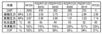
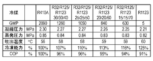
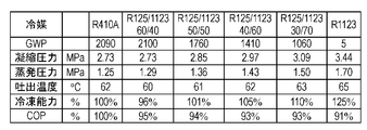
- FIG. 2 shows the pressure, temperature, and compression of the refrigeration cycle at a mixing ratio in which R32 is 30 wt% or more and 60 wt% or less in the mixed working fluid of R1123 and R32 in the first embodiment of the present invention. It is the figure which calculated the refrigerating capacity and cycle efficiency (COP) in case the displacement of a machine is the same, and compared with R410A and R1123.
- COP refrigerating capacity and cycle efficiency
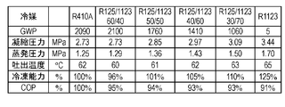
- FIG. 3 shows the pressure, temperature, and compression of the refrigeration cycle at a mixing ratio in which R32 is 30 wt% or more and 60 wt% or less in the mixed working fluid of R1123 and R32 in the first embodiment of the present invention. It is the figure which calculated the refrigerating capacity and cycle efficiency (COP) in case the displacement of a machine is the same, and compared with R410A and R1123.
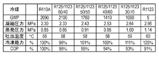
- FIG. 4 shows the pressure, temperature, and compression of the refrigeration cycle at a mixing ratio in which R125 is 30 wt% or more and 60 wt% or less in the mixed working fluid of R1123 and R125 in the first embodiment of the present invention.
- FIG. 5 shows the pressure, temperature, and compression of the refrigeration cycle in a mixed working fluid of R1123 and R125 in the first embodiment of the present invention at a mixing ratio where R125 is 30 wt% or more and 60 wt% or less. It is the figure which calculated the refrigerating capacity and cycle efficiency (COP) in case the displacement of a machine is the same, and compared with R410A and R1123.
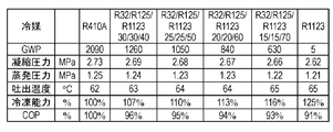
- FIG. 6 shows the refrigeration cycle pressure, temperature, and compressor displacement when the mixing ratio of R32 and R125 is fixed to 50% by weight and mixed with R1123 in the first embodiment of the present invention.
- FIG. 7 shows the refrigeration cycle pressure, temperature, and displacement of the compressor when the mixing ratio of R32 and R125 is fixed to 50% by weight and mixed with R1123 in the first embodiment of the present invention. It is the figure which computed the refrigerating capacity and cycle efficiency (COP) in the case of the same volume, and compared with R410A and R1123.
- FIG. 8 is a longitudinal sectional view of the scroll compressor according to the first embodiment of the present invention.
- FIG. 9 is an enlarged cross-sectional view of a main part of the compression mechanism portion of the scroll compressor according to the first embodiment of the present invention.
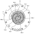
- FIG. 10 is a plan view showing the configuration of the compression chamber of the compression mechanism section of the scroll compressor according to the first embodiment of the present invention.
- FIG. 11 is a diagram for explaining a comparison of pressures in the respective compression chambers in the first embodiment (when a bypass hole is provided) and when it is not provided (comparative example).
- FIG. 12 is a plan view showing the configuration of the compression chamber of the compression mechanism portion of the scroll compressor according to the modification of the first embodiment of the present invention.
- FIG. 13 is a partial cross-sectional view showing a structure in the vicinity of the power supply terminal of the compressor according to the first embodiment of the present invention.
- FIG. 14 is a diagram for explaining the configuration of the refrigeration cycle apparatus according to the second embodiment of the present invention.
- FIG. 15 is a Mollier diagram for explaining the operation of the refrigeration cycle apparatus according to the second embodiment of the present invention.
- FIG. 16 is a Mollier diagram for describing the control operation of Modification 1 of the second embodiment of the present invention.
- FIG. 17 is a Mollier diagram showing the control operation of Modification 2 of the control method of the refrigeration cycle apparatus according to the second embodiment of the present invention.
- FIG. 18 is a diagram illustrating a pipe joint that constitutes a part of the pipe of the refrigeration cycle apparatus according to the second embodiment of this invention.
- FIG. 19 is a diagram showing a configuration of a refrigeration cycle apparatus according to the third embodiment of the present invention.
- FIG. 20 is a diagram showing a configuration of a refrigeration cycle apparatus according to the fourth embodiment of the present invention.
- FIG. 21 is a diagram showing the operation of the refrigeration cycle apparatus according to the fourth embodiment of the present invention on a Mollier diagram.
- FIG. 22 is an enlarged cross-sectional view of a main part of the compression mechanism portion of the scroll compressor according to the fifth embodiment of the present invention.
- FIG. 23 is a system configuration diagram of the refrigeration cycle apparatus using the compressor according to the sixth embodiment of the present invention.
- FIG. 24 shows the pressure, temperature, and compression of the refrigeration cycle in the mixed working fluid of R1123 and R32 in the sixth embodiment of the present invention at a mixing ratio where R32 is 30 wt% or more and 60 wt% or less.
- FIG. 25 shows the pressure, temperature, and compression of the refrigeration cycle in the mixed working fluid of R1123 and R32 in the sixth embodiment of the present invention at a mixing ratio where R32 is 30 wt% or more and 60 wt% or less. It is the figure which calculated the refrigerating capacity and cycle efficiency (COP) in case the displacement of a machine is the same, and compared with R410A and R1123.
- FIG. 25 shows the pressure, temperature, and compression of the refrigeration cycle in the mixed working fluid of R1123 and R32 in the sixth embodiment of the present invention at a mixing ratio where R32 is 30 wt% or more and 60 wt% or less.
- FIG. 26 shows the pressure, temperature, and compression of the refrigeration cycle in a mixed working fluid of R1123 and R125 in the sixth embodiment of the present invention at a mixing ratio where R125 is 30 wt% or more and 60 wt% or less. It is the figure which calculated the refrigerating capacity and cycle efficiency (COP) in case the displacement of a machine is the same, and compared with R410A and R1123.
- FIG. 27 shows the pressure, temperature, and compression of the refrigeration cycle at a mixing ratio in which R125 is 30 wt% or more and 60 wt% or less in the mixed working fluid of R1123 and R125 in the sixth embodiment of the present invention.
- FIG. 28 shows the refrigeration cycle pressure, temperature, and compressor displacement when the mixing ratio of R32 and R125 is fixed at 50% by weight and mixed with R1123 in the sixth embodiment of the present invention. It is the figure which computed the refrigerating capacity and cycle efficiency (COP) in the case of the same volume, and compared with R410A and R1123.
- FIG. 29 shows the refrigeration cycle pressure, temperature, and compressor displacement when the mixing ratio of R32 and R125 is fixed to 50% by weight and mixed with R1123 in the sixth embodiment of the present invention.
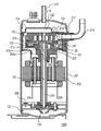
- FIG. 30 is a longitudinal sectional view of a scroll compressor according to the sixth embodiment of the present invention.
- FIG. 31 is an enlarged cross-sectional view of a main part of a compression mechanism portion of a scroll compressor according to the sixth embodiment of the present invention.
- FIG. 32 is a diagram showing a state in which the turning scroll is engaged with the fixed scroll according to the sixth embodiment of the present invention.
- FIG. 33 is a diagram showing pressure rise curves of the first compression chamber and the second compression chamber in the sixth embodiment of the present invention.
- FIG. 34 is a diagram showing a state in which the orbiting scroll is engaged with the fixed scroll and viewed from the back of the orbiting scroll in the sixth embodiment of the present invention.
- FIG. 35 is a partial cross-sectional view showing the structure in the vicinity of the power supply terminal of the scroll compressor according to the sixth embodiment of the present invention.
- FIG. 36 is a diagram for explaining the configuration of the refrigeration cycle apparatus according to the seventh embodiment of the present invention.
- FIG. 37 is a Mollier diagram for explaining the operation of the refrigeration cycle apparatus according to the seventh embodiment of the present invention.
- FIG. 38 is a Mollier diagram for describing the control operation of Modification 1 of the seventh embodiment of the present invention.
- FIG. 39 is a Mollier diagram showing the control operation of Modification 2 of the control method of the refrigeration cycle apparatus in the seventh embodiment of the present invention.
- FIG. 40 is a diagram showing a pipe joint that constitutes a part of the pipe of the refrigeration cycle apparatus according to the seventh embodiment of the present invention.
- FIG. 41 is a diagram showing a configuration of a refrigeration cycle apparatus according to the eighth embodiment of the present invention.
- FIG. 42 is a diagram showing a configuration of a refrigeration cycle apparatus according to the ninth embodiment of the present invention.
- FIG. 43 shows the operation of the refrigeration cycle apparatus according to the ninth embodiment of the present invention on a Mollier diagram.
- FIG. 44 is a sectional view of a scroll compressor according to the tenth embodiment of the present invention.
- FIG. 1 is a system configuration diagram of a refrigeration cycle apparatus 100 using a compressor 61 according to a first embodiment of the present invention.
- the refrigeration cycle apparatus 100 is mainly composed of a compressor 61, a condenser 62, a throttle mechanism 63, and an evaporator 64, for example, when a cycle exclusively for cooling is used. . And these apparatuses are connected so that a working fluid (refrigerant) may circulate by piping.
- a working fluid refrigerant
- the refrigerant changes to a liquid by at least one of pressurization and cooling, and changes to a gas by at least one of decompression and heating.
- the compressor 61 is driven by a motor, pressurizes the low-temperature and low-pressure gas refrigerant into the high-temperature and high-pressure gas refrigerant, and conveys it to the condenser 62.
- the condenser 62 the high-temperature and high-pressure gaseous refrigerant is cooled by air blown by a fan or the like and condensed to become a low-temperature and high-pressure liquid refrigerant.
- the liquid refrigerant is depressurized by the throttle mechanism 63, and a part of the liquid refrigerant becomes a low-temperature and low-pressure gas refrigerant, and the rest becomes a low-temperature and low-pressure liquid refrigerant and is conveyed to the evaporator 64.
- the low-temperature and low-pressure liquid refrigerant is heated and evaporated by air blown by a fan or the like, becomes a low-temperature and low-pressure gas refrigerant, and is again sucked into the compressor 61 and pressurized. Such a cycle is repeated.
- coolant flow path of at least any one of the condenser 62 and the evaporator 64 it is desirable that it is an aluminum-made refrigerant pipe containing aluminum or an aluminum alloy.
- a flat tube provided with a plurality of refrigerant flow holes is desirable for decreasing the condensation temperature or increasing the evaporation temperature.
- the working fluid (refrigerant, working refrigerant) sealed in the refrigeration cycle apparatus 100 of the present embodiment is composed of (1) R1123 (1,1,2-trifluoroethylene) and (2) R32 (difluoromethane). It is a two-component mixed working fluid, and in particular, R32 is a mixed working fluid of 30 wt% to 60 wt%.
- the disproportionation reaction of R1123 can be suppressed by mixing R32 with 30 wt% or more of R1123.
- R32 relaxes the disproportionation reaction due to the small polarization to fluorine atoms, and R1123 and R32 have similar physical characteristics, so that behavior during phase change such as condensation and evaporation
- the disproportionation reaction of R1123 can be suppressed by the action of reducing the disproportionation reaction opportunity due to the integration of.
- the mixed refrigerant of R1123 and R32 has an azeotropic boiling point with R32 being 30% by weight and R1123 being 70% by weight, and there is no temperature slip, so that it can be handled in the same manner as a single refrigerant.
- R32 is mixed in an amount of 60% by weight or more, temperature slip increases, and handling similar to that of a single refrigerant may be difficult. Therefore, it is desirable to mix R32 in an amount of 60% by weight or less.
- R32 should be mixed at a ratio of 40 wt% to 50 wt%. Is desirable.
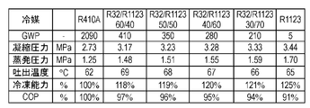
- FIGS. 2 and 3 show the pressure of the refrigeration cycle at a mixing ratio in which R32 is 30 wt% or more and 60 wt% or less of the mixed working fluid of R1123 and R32 in the first embodiment of the present invention, It is the figure which computed the refrigerating capacity in the case of the same temperature, the displacement of a compressor, and cycle efficiency (COP), and compared with R410A and R1123.
- the cooling calculation conditions in Fig. 2 correspond to the cooling operation of the air conditioner (indoor dry bulb temperature 27 ° C, wet bulb temperature 19 ° C, outdoor dry bulb temperature 35 ° C).
- the evaporation temperature was 15 ° C.
- the condensation temperature was 45 ° C.
- the superheated degree of the refrigerant sucked in the compressor was 5 ° C.
- the supercooling degree at the condenser outlet was 8 ° C.
- the heating calculation conditions in FIG. 3 are those corresponding to the heating operation of the air conditioner (indoor dry bulb temperature 20 ° C., outdoor dry bulb temperature 7 ° C., wet bulb temperature 6 ° C.), and the evaporation temperature is 2 ° C.
- the condensation temperature was 38 ° C.
- the superheat degree of the refrigerant sucked into the compressor was 2 ° C.
- the supercool degree at the condenser outlet was 12 ° C.
- a mixture containing R32 in a ratio of 30 wt% to 60 wt% is desirable. More desirably, a mixture containing R32 in a proportion of 40 wt% to 50 wt% is desirable.
- the working fluid sealed in the refrigeration cycle apparatus 100 of the present embodiment is a two-component consisting of (1) R1123 (1,1,2-trifluoroethylene) and (2) R125 (tetrafluoroethane).
- the mixed working fluid may be a mixed working fluid having R125 of 30 wt% or more and 60 wt% or less.
- the disproportionation reaction of R1123 can be suppressed by mixing R125 in an amount of 30% by weight or more.
- the higher the concentration of R125 the more the disproportionation reaction can be suppressed. This is because the disproportionation reaction is mitigated by the small polarization of R125 to fluorine atoms, and the physical properties of R1123 and R125 are similar, so the behavior during phase change such as condensation and evaporation is This is because the disproportionation reaction of R1123 can be suppressed by the action of reducing the disproportionation reaction opportunity by being integrated. Further, since R125 is a nonflammable refrigerant, R125 can reduce the combustibility of R1123.
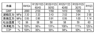
- FIG. 4 and FIG. 5 show the pressure of the refrigeration cycle at a mixing ratio in which R125 is 30 wt% or more and 60 wt% or less of the mixed working fluid of R1123 and R125 in the first embodiment of the present invention, It is the figure which computed the refrigerating capacity in the case of the same temperature, the displacement of a compressor, and cycle efficiency (COP), and compared with R410A and R1123.
- the calculation conditions in FIGS. 4 and 5 are the same as the calculation conditions in FIGS. 2 and 3, respectively.
- the refrigerating capacity is 96 to 110% as compared with R410A, and the cycle efficiency (COP) is It turns out that it becomes 94 to 97%.
- R125 at 40 wt% or more and 50 wt% or less, it is possible to prevent disproportionation of R1123 and to reduce the discharge temperature, so that the discharge temperature rises. Equipment design is facilitated. Furthermore, the warming potential can be reduced to 50-100% of R410A.
- the working fluid sealed in the refrigeration cycle apparatus of the present embodiment includes (1) R1123 (1,1,2-trifluoroethylene), (2) R32 (difluoromethane), and (3) R125 (tetra It may be a three-component mixed working fluid made of fluorethane.
- a mixed working fluid in which the mixing ratio of R32 and R125 is 30 to 60% by weight and the mixing ratio of R1123 is 40 to 70% by weight may be used.
- the disproportionation reaction of R1123 can be suppressed by setting the mixing ratio of R32 and R125 to 30% by weight or more. Further, the higher the mixing ratio of R32 and R125, the more the disproportionation reaction can be suppressed. Further, R125 can reduce the combustibility of R1123.
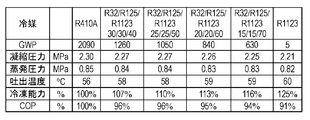
- FIGS. 6 and 7 show the pressure, temperature, and compression of the refrigeration cycle when the mixing ratio of R32 and R125 is fixed to 50% by weight and mixed with R1123 in the first embodiment of the present invention. It is the figure which calculated the refrigerating capacity and cycle efficiency (COP) in case the displacement of a machine is the same, and compared with R410A and R1123.
- the calculation conditions of FIGS. 6 and 7 are the same as the calculation conditions of FIGS. 2 and 3, respectively.
- the refrigerating capacity becomes 107 to 116% as compared with R410A, and the cycle It can be seen that the efficiency (COP) is 93 to 96%.
- the mixing ratio of R32 and R125 is set to 40% by weight or more and 50% by weight or less, disproportionation can be prevented, the discharge temperature can be reduced, and the combustibility can also be reduced. Furthermore, the warming potential can be reduced to 60-30% of R410A.
- the mixing ratio of R32 and R125 of the three-component working fluid has been described as 50 wt%, but the mixing ratio of R32 may be 0 wt% or more and 100 wt% or less.
- the mixing ratio of R32 may be increased.
- the mixing ratio of R32 is decreased and the mixing ratio of R125 is increased, the discharge temperature can be decreased and the combustibility can be decreased.
- R32 and R125 are mixed, and the sum of R32 and R125 is 30 wt% or more and 60 wt% or less.
- the resulting mixture is desirable. More preferably, a mixture containing 40% by weight or more and 50% by weight or less of the sum of R32 and R125 is desirable.
- FIG. 8 is a longitudinal sectional view of the scroll compressor 200 according to the first embodiment of the present invention
- FIG. 9 is an enlarged sectional view of a main part of the compression mechanism unit 2 of the scroll compressor 200
- 10 is a plan view showing the configuration of the compression chamber 15 of the compression mechanism section 2 of the scroll compressor 200. FIG. Hereinafter, the configuration, operation, and action of the scroll compressor 200 will be described.
- the scroll compressor 200 includes a hermetic container 1, and a compression mechanism unit 2, a motor unit 3, and an oil storage unit 20 therein.
- the compression mechanism section 2 includes a main bearing member 11 fixed in the sealed container 1 by welding or shrink fitting, a shaft 4 pivotally supported on the main bearing member 11, and bolts on the main bearing member 11.
- the fixed scroll 12 is provided.
- the compression mechanism portion 2 is configured by sandwiching a turning scroll 13 that engages with the fixed scroll 12 between the main bearing member 11 and the fixed scroll 12.
- a rotation restraining mechanism 14 such as an Oldham ring that guides the orbiting scroll 13 so as to prevent the rotation of the orbiting scroll 13 and move it in a circular orbit.
- the orbiting scroll 13 By turning the orbiting scroll 13 eccentrically by the eccentric shaft portion 4a at the upper end of the shaft 4, the orbiting scroll 13 can be moved in a circular orbit.
- Each of the fixed scroll 12 and the orbiting scroll 13 has a structure in which a spiral wrap rises (projects) from the end plate.
- the compression chamber 15 formed between the fixed scroll 12 and the orbiting scroll 13 moves the working refrigerant from the outer peripheral side toward the center while reducing the volume.
- the working refrigerant is sucked in through the suction pipe 16 connected to the suction pipe 16 and the suction port 17 in the outer peripheral portion of the fixed scroll 12, is closed in the compression chamber 15, and is compressed.
- the working refrigerant that has reached a predetermined pressure is different from the discharge hole 18 on the end plate of the fixed scroll 12 and the discharge hole 18 that is a through hole formed in the center portion (end plate center position) of the fixed scroll 12.
- the reed valve 19 (check valve) is pushed open from the circular bypass hole 68, which is a through hole, formed in the discharge hole 31 and discharged into the discharge chamber 31.
- the discharge chamber 31 is a space formed by a muffler 32 provided so as to cover the discharge hole 18.
- the working refrigerant discharged into the discharge chamber 31 is discharged into the sealed container 1 through the communication path provided in the compression mechanism unit 2.
- the working refrigerant discharged into the sealed container 1 is discharged from the sealed container 1 to the refrigeration cycle apparatus 100 through the discharge pipe 50.
- a valve stop 69 for regulating the lift amount is provided.
- the reed valve 19 is provided, for example, on the end plate surface at the position where the bypass hole 68 of the end plate of the fixed scroll 12 is formed.
- a pump 25 is provided at the other end of the shaft 4, and the suction port of the pump 25 is disposed in the oil storage unit 20. Since the pump 25 is driven simultaneously with the scroll compressor 200, the compressor lubricating oil 6 (oil, refrigerating machine oil) in the oil storage section 20 provided at the bottom of the hermetic container 1 is related to the pressure condition and the operating speed. It can be sucked up reliably, and the worry of running out of oil is also eliminated.
- the compressor lubricating oil 6 sucked up by the pump 25 is supplied to the compression mechanism section 2 through an oil supply hole 26 penetrating the shaft 4 (see FIG. 9).
- the compressor lubricating oil 6 can be prevented from being mixed into the compression mechanism 2 by removing foreign matter with an oil filter or the like before being sucked up by the pump 25 or after being sucked up. It is possible to improve the performance.
- the compressor lubricating oil 6 guided to the compression mechanism unit 2 also serves as a back pressure source for the orbiting scroll 13 having a pressure substantially equal to the discharge pressure of the scroll compressor 200.
- the orbiting scroll 13 does not move away from the fixed scroll 12 or is not biased, and exhibits a predetermined compression function stably.
- a part of the compressor lubricating oil 6 is obtained from the fitting portion between the eccentric shaft portion 4a and the orbiting scroll 13 and the shaft 4 and the main bearing member 11 so as to obtain a clearance by the supply pressure and the own weight. After entering the bearing portion 66 between them and lubricating each portion, it falls and returns to the oil storage portion 20.
- the seal member 78 is partitioned into the high pressure region 30 and the outside of the seal member 78 is divided into the back pressure chamber 29.
- the pressure in the high pressure region 30 and the pressure in the back pressure chamber 29 can be completely separated, the pressure load from the back surface 13e of the orbiting scroll 13 can be stably controlled.
- the compression chamber 15 formed by the fixed scroll 12 and the orbiting scroll 13 includes first compression chambers 15a-1 and 15a-2 formed on the wrap outer wall side of the orbiting scroll 13, and a first compression chamber 15a formed on the wrap inner wall side.
- This configuration in which compression chambers are formed on the outer wall side and the inner wall side of the wrap is referred to as “a configuration in which compression chambers are formed in both directions”.
- the gas sucked into each compression chamber 15 swirls. Along with the turning motion of the scroll 13, it moves to the center while reducing the volume.
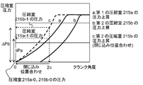
- FIG. 11 shows the compression of the first embodiment of the present invention (when the bypass holes 68a-1, 68a-2, 68b-1, 68b-2 are provided) and when it is not provided (comparative example).
- FIG. 6 is a view for explaining a comparison of pressures in a chamber 15.
- the bypass holes 68a-1, 68a-2, 68b-1, and 68b-2 are provided at positions that communicate with the compression chamber 15 earlier than the discharge holes 18 (at an earlier timing). Yes. As a result, the pressure in the compression chamber 15 reaches the discharge pressure, and at the same time, the discharge into the discharge chamber 31 is started through the bypass holes 68a-1, 68a-2, 68b-1, and 68b-2.
- the structure which can suppress a raise can be implement
- bypass holes 68a-1, 68a-2, 68b-1, 68b-2 circular communication holes, the area of the bypass holes 68a-1, 68a-2, 68b-1, 68b-2 is reduced.
- the flow path resistance can be configured to be the minimum as compared with the case of other shapes.
- the first compression chambers 15a-1, 15a-2 (solid line) and the second compression chambers 15b-1, 15b-2 (broken line) each reach the discharge pressure.
- the crank rotation angle is different. Therefore, in the present embodiment, the bypass holes 68a-1 and 68a-2 communicate only with the first compression chambers 15a-1 and 15a-2, and the bypass holes 68b-1 and 68b-2 are in the second compression chamber.
- FIG. 12 is a plan view showing the configuration of the compression chamber 15 of the compression mechanism unit 2 of the scroll compressor 200 according to the modification of the first embodiment of the present invention.
- the bypass hole 68ab is provided at a position communicating with both the first compression chamber 15a and the second compression chamber 15b by the orbiting motion of the orbiting scroll 13.
- the diameter of the bypass hole 68ab is made smaller than the thickness of the orbiting scroll wrap 13c so as not to open to the first compression chamber 15a and the second compression chamber 15b.
- the bypass hole 68ab-1 communicates with the second compression chamber 15b-1
- the bypass hole 68ab-3 communicates with the first compression chamber 15a-1. It plays a role in preventing over-compression.
- the bypass hole 68ab has the first compression chamber 15a-1 and the second compression chamber 15a-1. It does not communicate with any of the compression chambers 15b-1. Thereby, since the temperature rise can be suppressed without causing working refrigerant leakage between the compression chambers, the disproportionation reaction of R1123 can be suppressed.
- polyol ester oil is used as the compressor lubricating oil.
- the polyol ester of the present invention is not limited to a specific type, at least one selected from the group consisting of neopentyl glycol, trimethylolpropane, pentaerythritol, and dipentaerythritol is used as a constituent alcohol.
- the viscosity of the refrigerating machine oil can be widely adjusted. According to this configuration, since the viscosity of the refrigerating machine oil can be freely adjusted, an oil film between the vane and the piston can be secured, and generation of sliding heat can be suppressed. Further, since the carbonyl group of the polyol ester oil supplements a radical that triggers the disproportionation reaction, the disproportionation reaction of R1123 can be suppressed.
- the constituent fatty acid of the polyol ester of the present invention is not limited to a specific one, but it is optimal to use a fatty acid having 6 to 12 carbon atoms.
- the constituent fatty acid may be a straight-chain fatty acid or a branched-chain fatty acid, but the straight-chain fatty acid has the ability to trap radicals because the carbonyl group is not sterically shielded by an alkyl group. high.
- an antiwear agent As an additive added to the lubricating oil 6 for a compressor, an antiwear agent, an antioxidant, a polymerization inhibitor, a reactant adsorbent, and the like can be used.
- Antiwear agents include phosphate ester, phosphite, thiophosphate, and the like, but phosphate esters that do not adversely affect the refrigeration cycle apparatus are optimal.
- phosphate esters include tributyl phosphate, tripentyl phosphate, trihexyl phosphate, triheptyl phosphate, trioctyl phosphate, trinonyl phosphate, tridecyl phosphate, triundecyl phosphate, tridodecyl phosphate, tritridecyl phosphate.
- Tritetradecyl phosphate tripentadecyl phosphate, trihexadecyl phosphate, triheptadecyl phosphate, trioctadecyl phosphate, trioleyl phosphate, triphenyl phosphate, tricresyl phosphate, trixylenyl phosphate, cresyl diphenyl phosphate, and Examples include xylenyl diphenyl phosphate.
- phosphate ester-based antiwear agent is added to the refrigerating machine oil in an amount of 0.1 to 3 wt%, so that it is efficiently adsorbed on the surface of the sliding part and creates a film with a small shearing force on the sliding surface. Thus, an anti-wear effect can be obtained.
- the wear preventive agent is adsorbed on the surface of the sliding portion to reduce friction, so that heat generation can be suppressed and the self-decomposition reaction of the R1123 refrigerant can be suppressed.
- phenolic antioxidants include propyl gallate, 2,4,5-trihydroxybutyrophenone, t-butylhydroquinone, nordihydroguaiaretic acid, butylhydroxyanisole, 4-hydroxymethyl-2, 6-di-t-butylphenol, octyl gallate, butylhydroxytoluene, dodecyl gallate and the like can be used.
- phenolic antioxidants include propyl gallate, 2,4,5-trihydroxybutyrophenone, t-butylhydroquinone, nordihydroguaiaretic acid, butylhydroxyanisole, 4-hydroxymethyl-2, 6-di-t-butylphenol, octyl gallate, butylhydroxytoluene, dodecyl gallate and the like can be used.
- radicals can be efficiently captured and reaction can be prevented. It is also possible to minimize the coloring of the base oil itself by the antioxidant.
- the phenol-based antioxidant can effectively capture the radicals generated in the sealed container 1, thereby obtaining an effect of suppressing the decomposition reaction of R1123.
- the scroll compressor 200 of the present embodiment and the refrigeration cycle apparatus 100 using the scroll compressor 200 are closed systems, and lubricating oil is sealed as a base oil as described above.
- the viscosity of the lubricating oil that is the base oil enclosed in the scroll compressor 200 is generally about 32 mm 2 / s to 68 mm 2 / s, while the viscosity of limonene is about 0.2 mm. The viscosity is considerably low at about 8 mm 2 / s.
- the viscosity of the lubricating oil is 60 mm 2 / s when limonene is mixed about 5%, 48 mm 2 / s when 15% is mixed, and 32 mm 2 / s when 35% is mixed. Go down. Therefore, when a large amount of limonene is mixed in an attempt to prevent the reaction of R1123, the scroll compressor 200 and the refrigeration compressor 200 and the refrigeration are caused by a decrease in the viscosity of the lubricating oil, wear due to poor lubrication, and generation of metal soap due to metal contact with the sliding surface. The reliability of the cycle device 100 is affected.
- the lubricating oil of the scroll compressor 200 of the present embodiment is preliminarily provided with a high-viscosity lubricating oil in order to compensate for the decrease in the viscosity of the base oil caused by mixing the limonene in an amount suitable for preventing reaction.
- a proper lubricating oil viscosity is ensured by using a base or mixing an ultra-high viscosity lubricating oil in an amount equal to or greater than the amount of limonene.
- the viscosity of the lubricating oil when mixing 5% limonene is 78 mm 2 / s
- the viscosity of the lubricating oil when mixing 35% limonene is about 230 mm 2 / s.
- a viscosity of 68 mm 2 / s can be secured.
- extreme examples such as increasing the amount of limonene mixed to 70% or 80% are also conceivable.
- the viscosity of the lubricating oil of high viscosity as the base each becomes a 8500 mm 2 / s or 25000 mm 2 / s, exceeds 3200 mm 2 / s which is the maximum value of the ISO standard.
- uniform mixing with limonene becomes difficult, practical application is considered difficult.
- a viscosity of 32 mm 2 / s to 68 mm 2 / s can be obtained by mixing lubricating oil of 800 mm 2 / s to 1000 mm 2 / s.
- a lubricating oil having a relatively uniform composition viscosity can be obtained by adding the ultra-high viscosity oil to limonene while adding small amounts.
- limonene is used as an example, but the same effect can be obtained with terpenes or terpenoids.
- hemiterpenes isoprene, prenol, 3-methylbutanoic acid and monoterpenes geranyl diphosphate, cineol, pinene and sesquiterpenes farnesyl diphosphate, artemisinin, bisabolol, diterpenes geranylgeranyl diphosphate, retinol, Retinal, phytol, paclitaxel, forskolin, aphidicolin and triterpene squalene, and lanosterol can be selected according to the operating temperature of the scroll compressor 200 and the refrigeration cycle apparatus 100 and the required lubricating oil viscosity.
- the illustrated viscosity is a specific example in the scroll compressor 200 having a high-pressure vessel, but a low-pressure vessel in which a relatively low viscosity lubricating oil of 5 mm 2 / s to 32 mm 2 / s is used.
- a relatively low viscosity lubricating oil of 5 mm 2 / s to 32 mm 2 / s is used. The same effect can be obtained with the scroll compressor 200 having the same effect.
- terpenes and terpenoids such as limonene have solubility in plastics, but if they are mixed at about 30% or less, the influence is slight, and the electric power required for plastics in the scroll compressor 200 is small. It is not at a level where insulation is a problem. However, when long-term reliability is required, and when there is a problem such as when the operating temperature is always high, it is desirable to use polyimide, polyimide amide, or polyphenylene sulfide having chemical resistance. .
- varnish is applied and baked on the conductor via an insulating coating on the winding of the motor unit 3 of the scroll compressor 200 of the present embodiment.
- thermosetting insulating material include a polyimide resin, an epoxy resin, and an unsaturated polyester resin.
- the polyimide resin can be converted into a polyimide by coating in the state of polyamic acid as a precursor and baking at around 300 ° C. It is known that the imidization reaction occurs by a reaction between an amine and a carboxylic acid anhydride.
- the R1123 refrigerant may react even in a short circuit between the electrodes, on the motor winding (mainly a polyimide precursor formed by reacting an aromatic diamine and an aromatic tetracarboxylic dianhydride)
- a short circuit between the electrodes By applying the polyimide acid varnish, a short circuit between the electrodes can be prevented.
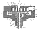
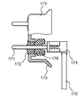
- FIG. 13 is a partial cross-sectional view showing the structure in the vicinity of the power supply terminal of the scroll compressor 200 according to the first embodiment of the present invention.
- a donut-shaped insulating member 76 that is in close contact with the glass insulator 72 that is an insulating member is disposed on the power supply terminal 71 inside the sealed container 1 of the scroll compressor 200. It is touched.
- the donut-shaped insulating member 76 maintains the insulating property, and is optimally resistant to hydrofluoric acid. Examples thereof include ceramic insulators and HNBR rubber donut spacers. It is essential that the doughnut-shaped insulating member 76 is in close contact with the glass insulator 72, but it is preferable that the donut-like insulating member 76 is also in close contact with the connection terminal.
- the power supply terminal 71 configured in this manner has a long creepage distance between the power supply terminal and the inner surface of the scroll compressor 200 due to the donut-shaped insulating member 76, prevents terminal tracking, and discharge energy of R1123. Can prevent ignition. Further, it is possible to prevent the hydrofluoric acid generated by the decomposition of R1123 from corroding the glass insulator 72.
- the scroll compressor 200 may be a so-called high pressure shell type compressor in which the discharge port is opened in the sealed container 1 and the sealed container 1 is filled with the refrigerant compressed in the compression chamber 15. .
- a so-called low-pressure shell type scroll compressor 200 in which the suction port 17 is opened in the sealed container 1 and the inside of the sealed container 1 is filled with the refrigerant before being compressed in the compression chamber 15 may be used.
- the temperature reduction due to the introduction of the low-temperature refrigerant in the compression chamber 15 becomes more prominent. It is desirable to suppress the disproportionation reaction.
- the refrigerant discharged from the discharge port is passed around the motor unit 3 and heated by the motor unit 3 in the sealed container 1, and then the sealed container is discharged from the discharge pipe 50. 1 may be configured to be discharged to the outside. According to this configuration, even if the temperature of the refrigerant discharged from the discharge pipe 50 is equal, the refrigerant temperature in the compression chamber 15 can be lowered, which is desirable in suppressing the disproportionation reaction of R1123.
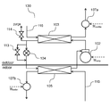
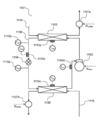
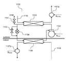
- FIG. 14 is a diagram for explaining the configuration of the refrigeration cycle apparatus 101 according to the second embodiment of the present invention.
- a compressor 102, a condenser 103, an expansion valve 104 that is a throttling mechanism, and an evaporator 105 are connected in this order through a refrigerant pipe 106 to constitute a refrigeration cycle circuit.
- a working fluid (refrigerant) is enclosed in the refrigeration cycle circuit.
- a fin-and-tube heat exchanger As the condenser 103 and the evaporator 105, when the surrounding medium is air, a fin-and-tube heat exchanger, a parallel flow type (microtube type) heat exchanger, or the like is used.
- the condenser 103 and the evaporator 105 when the surrounding medium is brine or a refrigerant of a binary refrigeration cycle apparatus a double tube heat exchanger, a plate heat exchanger, or shell and tube heat is used. An exchanger is used.
- expansion valve 104 for example, a pulse motor drive type electronic expansion valve or the like is used.
- a fluid machine 107 a that is a first transport unit that drives (flows) an ambient medium (first medium) that exchanges heat with a refrigerant to a heat exchange surface of the condenser 103.
- the evaporator 105 is provided with a fluid machine 107b that is a second transport unit that drives (flows) an ambient medium (second medium) that exchanges heat with the refrigerant to the heat exchange surface of the evaporator 105.
- a flow path 116 for the surrounding medium is provided for each surrounding medium.
- the refrigeration cycle apparatus 101 is a binary refrigeration cycle apparatus, a refrigerant that is preferable for the refrigeration cycle circuit and the operating temperature range, such as hydrofluorocarbon (HFC), hydrocarbon (HC), or carbon dioxide, is used. .
- HFC hydrofluorocarbon
- HC hydrocarbon
- carbon dioxide carbon dioxide
- the fluid machines 107a and 107b for driving the surrounding medium when the surrounding medium is air, an axial blower such as a propeller fan, a cross flow blower, or a centrifugal blower such as a turbo blower is used, and the surrounding medium is brine.
- a centrifugal pump or the like is used.
- the compressor 102 serves as the fluid machines 107a and 107b for transporting the surrounding medium.
- a condensing temperature detecting unit is provided at a location where the refrigerant flowing in the inside of the condenser 103 flows in two phases (a state where gas and liquid are mixed) (hereinafter referred to as “two-phase tube of the condenser”). 110a is installed, and the refrigerant temperature can be measured.
- a condenser outlet temperature detector 110b is installed between the outlet of the condenser 103 and the inlet of the expansion valve 104.
- the condenser outlet temperature detector 110b can detect the degree of supercooling at the inlet of the expansion valve 104 (a value obtained by subtracting the temperature of the condenser 103 from the inlet temperature of the expansion valve 104).
- an evaporation temperature detection unit 110 c is provided at a portion where the refrigerant flowing in the evaporator flows in two phases (hereinafter referred to as “two-phase pipe of the evaporator” in this specification). It is possible to measure the temperature of the refrigerant.
- a suction temperature detector 110d is provided in the suction part of the compressor 102 (between the outlet of the evaporator 105 and the inlet of the compressor 102). As a result, the temperature of the refrigerant sucked into the compressor 102 (intake temperature) can be measured.
- an electronic thermostat that is contact-connected with a pipe through which a refrigerant flows or an outer pipe of a heat transfer pipe may be used, or a sheath pipe system that directly contacts the working fluid. In some cases, an electronic thermostat is used.
- a high pressure side pressure detector 115a is installed.
- a low-pressure side pressure detector 115b that detects the pressure on the low-pressure side of the refrigeration cycle circuit (region where the refrigerant from the outlet of the expansion valve 104 to the inlet of the compressor 102 exists at low pressure) is installed. ing.
- the high-pressure side pressure detection unit 115a and the low-pressure side pressure detection unit 115b for example, a device that converts the displacement of the diaphragm into an electrical signal is used.
- a differential pressure gauge (measuring means for measuring the pressure difference at the inlet / outlet of the expansion valve 104) may be used instead of the high pressure side pressure detector 115a and the low pressure side pressure detector 115b.
- the refrigeration cycle apparatus 101 is described as including all the temperature detection units and each pressure detection unit. However, a detection unit that does not use a detection value in the control described later. Can be omitted.
- the degree of superheat of the working fluid at the suction portion of the compressor 102 which is the temperature difference between the suction temperature detection portion 110d and the evaporation temperature detection portion 110c, is calculated. Then, the expansion valve 104 is controlled so that this superheat degree becomes a predetermined target superheat degree (for example, 5K).
- a discharge temperature detection unit (not shown) in the discharge unit of the compressor 102 and perform control using the detected value.
- the degree of superheat of the working fluid at the discharge part of the compressor 102 which is the temperature difference between the discharge temperature detection part and the condensation temperature detection part 110a, is calculated.
- the expansion valve 104 is controlled so that this superheat degree becomes a predetermined target superheat degree.
- control is performed to open the expansion valve 104 and reduce the pressure and temperature of the high-pressure side working fluid in the refrigeration cycle apparatus 101. Is called.
- the temperature at the critical point (critical temperature) is taken as a guide, and the expansion valve is kept from approaching the temperature within a predetermined value (5 K) from this temperature.
- the opening degree of 104 is controlled.
- the critical temperature of the mixed refrigerant is used to control the temperature of the working fluid so that it does not become (critical temperature ⁇ 5 ° C.) or higher.
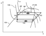
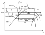
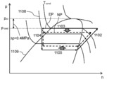
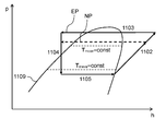
- FIG. 15 is a Mollier diagram for explaining the operation of the refrigeration cycle apparatus 101 according to the second embodiment of the present invention.
- FIG. 15 shows an isotherm 108 and a saturated liquid / saturated vapor line 109.
- a refrigeration cycle under an excessive pressure condition that causes a disproportionation reaction is indicated by a solid line (EP), and a refrigeration cycle under normal operation is indicated by a broken line (NP).
- the control is performed.
- the device controls the opening of the expansion valve 104 to the opening side.
- the condensing pressure on the high-pressure side of the refrigeration cycle apparatus 101 decreases as shown by NP in FIG. 15, so that it becomes possible to suppress the disproportionation reaction caused by excessive increase in the refrigerant pressure. Even when the leveling reaction occurs, the pressure rise can be suppressed.
- the above-described control method is a method of indirectly grasping the pressure in the condenser 103 from the condensation temperature measured by the condensation temperature detection unit 110a and controlling the opening degree of the expansion valve 104.
- the working fluid containing R1123 is azeotropic or pseudoazeotropic, and there is no or small temperature difference (temperature gradient) between the dew point and boiling point of the working fluid containing R1123 in the condenser 103.
- the condensation temperature can be used as an index instead of the condensation pressure, which is particularly preferable.
- ⁇ Modification 1 of Control Method> As described above, by comparing the critical temperature and the condensation temperature, the state of high pressure (refrigerant pressure in the condenser 103) of the refrigeration cycle apparatus 101 is indirectly detected, and an appropriate operation is performed on the expansion valve. Instead of the control method instructing 104 or the like, a method of controlling the opening degree of the expansion valve 104 based on the directly measured pressure may be used.
- FIG. 16 is a Mollier diagram for explaining the control operation of the first modification of the second embodiment of the present invention.
- FIG. 16 a refrigeration cycle in which an excessive pressure rise is occurring from the discharge portion of the compressor 102 to the inlets of the condenser 103 and the expansion valve 104 is indicated by a solid line (EP) and indicated by a broken line (NP) as described above.
- the refrigeration cycle in a state of being released from the excessive pressure state is shown.
- the working fluid including R1123 is changed from the discharge port of the compressor 102 to the inlet of the expansion valve 104. Therefore, it is determined that the disproportionation reaction has occurred or is likely to occur, and the opening of the expansion valve 104 is controlled so as to avoid the sustaining under the high pressure condition.
- the refrigeration cycle in FIG. 16 acts on the side where the high pressure (condensation pressure) decreases, as indicated by NP in the figure, and causes the disproportionation reaction or after the disproportionation reaction.
- the pressure rise which arises can be suppressed.
- This control method is preferably used when the working fluid including R1123 is in a non-azeotropic state, particularly when the temperature gradient is large at the condensation pressure.
- ⁇ Modification 2 of control method> Note that a control method based on the degree of supercooling may be used instead of the control method based on the critical temperature or critical pressure described above.
- FIG. 17 is a Mollier diagram showing the control operation of the second modification of the control method of the refrigeration cycle apparatus 101 in the second embodiment of the present invention.
- the temperature of the refrigerant in the condenser 103 is changed to the surrounding medium by appropriate control of the refrigeration cycle, the heat exchanger size, and the refrigerant charge amount optimization such as the expansion valve 104 and the compressor 102.
- the temperature is set to be higher to a certain extent.
- the degree of supercooling generally takes a value of about 5K. Similar measures are taken for the working fluid including R1123 used in the same refrigeration cycle apparatus 101.
- the opening degree of the expansion valve 104 is controlled based on the degree of supercooling of the refrigerant at the inlet of the expansion valve 104.
- the degree of supercooling of the refrigerant at the inlet of the expansion valve 104 during normal operation is assumed to be 5K, and the opening degree of the expansion valve 104 is controlled using 15K, which is three times the value as a guide. I have decided.
- the reason why the degree of supercooling as the threshold is tripled is that the degree of supercooling may change within that range depending on the operating conditions.
- the degree of supercooling is calculated from the detection value of the condensation temperature detection unit 110a and the detection value of the condenser outlet temperature detection unit 110b.
- the degree of supercooling is a value obtained by subtracting the detection value of the condenser outlet temperature detection unit 110b from the detection value of the condensation temperature detection unit 110a.
- the degree of supercooling at the inlet of the expansion valve 104 reaches a predetermined value (15K)
- the expansion valve 104 is operated to open the opening, and the condensation pressure that is the high-pressure portion of the refrigeration cycle apparatus 101 is operated. Is controlled in the direction of lowering (broken line to broken line in FIG. 17).
- the condensing pressure is decreased, because the condensation temperature is equivalent to decrease, it decreases from condensation temperature T cond 1 to T cond2, supercooling degree of the expansion valve 104 inlet, the T cond 1 -T EXIN, The degree of supercooling decreases to T cond2 ⁇ T exin (here, it is assumed that the working fluid temperature at the inlet of the expansion valve 104 does not change but is T exin ). As described above, the degree of supercooling decreases as the condensing pressure in the refrigeration cycle apparatus 101 decreases, so that the condensing pressure in the refrigeration cycle apparatus 101 can be controlled even when the degree of supercooling is used as a reference. I understand.
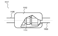
- FIG. 18 is a view showing a pipe joint 117 constituting a part of the pipe of the refrigeration cycle apparatus 101 according to the second embodiment of the present invention.
- the refrigeration cycle apparatus 101 of the present invention When the refrigeration cycle apparatus 101 of the present invention is used in, for example, a home-use split-type air conditioner (air conditioner), the refrigeration cycle apparatus 101 includes an outdoor unit having an outdoor heat exchanger and an indoor heat exchanger. And an indoor unit. The outdoor unit and the indoor unit cannot be integrated due to the configuration. Therefore, the outdoor unit and the indoor unit are connected at the installation location using a mechanical joint such as the union flare 111 shown in FIG.
- a mechanical joint such as the union flare 111 shown in FIG.
- connection state of the mechanical joint is deteriorated due to causes such as omission of work, the refrigerant leaks from the joint part, which adversely affects the equipment performance.
- the working fluid itself including R1123 is a greenhouse gas having a warming effect, there is a possibility of adversely affecting the global environment. Therefore, it is required to quickly detect and repair the refrigerant leakage.
- the refrigerant leak detection method includes a method of applying a detection agent to the site and detecting whether or not a bubble is generated, and a method of using a detection sensor. large.
- a seal 112 containing a polymerization accelerator is wound around the outer periphery of the union flare 111 to facilitate detection of refrigerant leakage and to reduce the amount of leakage.
- polytetrafluoroethylene which is one of fluorinated carbon resins
- the working fluid containing R1123 and the polymerization accelerator are intentionally brought into contact with each other at a leaking location, and polytetrafluoroethylene is precipitated and solidified at the leaking location.
- the generation site of polytetrafluoroethylene is the leakage site of the working fluid containing R1123, the polymerization product is naturally generated and adhered to the site that prevents the leakage, so it is also possible to reduce the amount of leakage. It becomes.
- FIG. 19 is a diagram showing a configuration of a refrigeration cycle apparatus 130 according to the third embodiment of the present invention.
- the difference in configuration between the refrigeration cycle apparatus 130 shown in FIG. 19 and the refrigeration cycle apparatus 101 of the second embodiment is newly connected to the inlet and outlet of the expansion valve 104 and a bypass pipe having an on-off valve. 113 is installed.
- a purge line having a relief valve 114 is provided between the outlet of the condenser 103 and the inlet of the expansion valve 104.
- the opening side of the relief valve 114 is arranged outside the room.
- the control method described in the second embodiment for example, an expansion valve so that the value obtained by subtracting the working fluid temperature measured by the two-phase pipe of the condenser 103 from the critical temperature of the working fluid including R1123 becomes 5K or more.
- 104 and a control method for controlling the difference between the critical pressure of the working fluid and the pressure detected by the high-pressure side pressure detector 115a to be 0.4 MPa or more. Even when the opening degree of the valve 104 is opened, there is a possibility that there is no improvement in the pressure drop, or a situation where the pressure drop speed is desired to be increased.
- the operating fluid pressure on the high pressure side is rapidly increased by opening the on-off valve provided in the bypass pipe 113 of the present embodiment and allowing the refrigerant to flow through the bypass pipe 113. It is possible to suppress the breakage of the refrigeration cycle apparatus 130.
- the refrigeration cycle apparatus 130 can be prevented from being damaged if the compressor 102 is emergency stopped. More preferred above. In the case of emergency stop of the compressor 102, it is desirable not to stop the fluid machines 107a and 107b in order to rapidly reduce the working fluid pressure on the high pressure side.
- the difference between the critical temperature of the working fluid and the condensation temperature detected by the condensation temperature detector 110a is less than 5K. Or a case where the difference between the critical pressure of the working fluid and the pressure detected by the high pressure side pressure detector 115a is less than 0.4 MPa. In such a case, since the refrigerant pressure in the refrigeration cycle apparatus 130 may further increase, it becomes necessary to escape the high-pressure refrigerant to the outside and prevent the refrigeration cycle apparatus 130 from being damaged. Therefore, control is performed to open the relief valve 114 that purges the working fluid including R1123 in the refrigeration cycle apparatus 130 to the external space.
- the installation position of the relief valve 114 in the refrigeration cycle apparatus 130 is preferably on the high pressure side. Further, from the outlet of the condenser 103 shown in the present embodiment to the inlet of the expansion valve 104 (at this position, since the working fluid is in a high-pressure supercooled liquid state, a steep pressure increase associated with the disproportionation reaction occurs. The resulting water hammer effect is likely to occur), or from the discharge part of the compressor 102 to the inlet of the condenser 103 (at this position, the working fluid exists in a gas state of high temperature and high pressure, so the molecular motion becomes active. It is particularly preferable to install it over a point where the disproportionation reaction itself is likely to occur.
- the relief valve 114 is provided on the outdoor unit side.
- the working fluid is not released to the indoor display space, and if it is a refrigeration unit, the working fluid is not released to the product display side such as a showcase. Therefore, it can be said that it is a form that is considered so as not to directly affect humans and commercial materials.
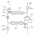
- FIG. 20 is a diagram showing a configuration of a refrigeration cycle apparatus 140 according to the fourth embodiment of the present invention.
- the difference in configuration between the refrigeration cycle apparatus 140 shown in FIG. 20 and the refrigeration cycle apparatus 101 of the second embodiment is that the first medium detects the temperature of the first medium before flowing into the condenser 103.
- a temperature detection unit 110e and a second medium temperature detection unit 110f that detects the temperature of the second medium before flowing into the evaporator 105 are provided. Further, the detected values of each temperature detection unit and each pressure detection unit, and the input power of the compressor 102 and the fluid machines 107a and 107b are recorded in an electronic recording device (not shown) for a certain period of time. Is also different.
- FIG. 21 is a diagram showing the operation of the refrigeration cycle apparatus 140 according to the fourth embodiment of the present invention on a Mollier diagram.
- the refrigeration cycle indicated by EP indicates the condensation pressure when the disproportionation reaction occurs
- the refrigeration cycle indicated by NP indicates the refrigeration cycle during normal operation.
- the cycle change at the time when the condensation pressure rises eg, the difference in evaporation pressure between NP and EP, etc. is not shown in order to simplify the explanation.
- the causes of the sudden rise in the condensation temperature of the working fluid including R1123, measured by the two-phase tube in the condenser 103, are (1) a sudden rise in ambient medium temperatures T mcon and T meva , and (2) compression.
- the pressurizing action due to the power increase of the machine 102, and (3) the flow change of the surrounding medium (the power increase of any of the fluid machines 107a and 107b driving the surrounding medium) can be considered.
- a pressurizing action by a disproportionation reaction can be mentioned as an event specific to the working fluid including R1123. Therefore, in this embodiment, in order to specify that the disproportionation reaction of (4) has occurred, it is determined and controlled that the events from (1) to (3) have not occurred.
- the expansion valve 104 when the change amount of the condensing temperature of the working fluid including R1123 is larger than the change amount of the temperature or input power of (1) to (3), the expansion valve 104 is used. Control to open side.
- control since it is difficult to compare the amount of change in temperature with the amount of change in input power value under the same standard, when measuring the amount of change in temperature, control is performed so that the input power does not change. That is, when measuring the amount of temperature change, the motor speeds of the compressor 102 and the fluid machines 107a and 107b are kept constant.
- the temperature change amount is measured at a certain time interval, for example, for 10 seconds to 1 minute. Prior to this measurement, for example, about 10 seconds to 1 minute before, control is performed so that the input electric energy of the compressor 102 and the fluid machines 107a and 107b is kept at a constant value. At this time, the amount of change per unit time of the input electric energy of the compressor 102 and the fluid machines 107a and 107b is substantially zero.
- “substantially” zero is defined as the change in the suction state of the compressor 102 due to the refrigerant bias in the compressor 102, or the first medium and the second medium in the fluid machines 107a and 107b are ambient air. This is because in some cases, the input power slightly fluctuates due to the influence of wind blowing or the like. That is, “substantially zero” means that it includes a slight fluctuation and is smaller than a predetermined value.
- the amount of change per unit time of the condensation temperature measured by the condensation temperature detection unit 110a per unit time of the temperature of the first medium detected by the first medium temperature detection unit 110e If the amount of change is greater than either the amount of change per unit time of the temperature of the second medium detected by the second medium temperature detector 110f, it is considered that a disproportionation reaction has occurred,
- the expansion valve 104 is controlled in the opening direction.
- a bypass is provided in parallel with the expansion valve 104, as shown in the third embodiment, in case the pressure increase caused by the disproportionation reaction cannot be controlled.
- a pipe 113 may be provided, the compressor 102 may be stopped urgently, and further, a means such as a relief valve 114 for reducing the pressure by discharging the refrigerant to the outside may be provided.
- control example of the expansion valve 104 that performs control based on the amount of change of the temperature detection unit installed in the two-phase pipe of the condenser 103 has been shown.
- the amount of change in pressure at any point from the section to the inlet of the expansion valve 104 may be used as a reference, or the amount of change in the degree of supercooling at the inlet of the expansion valve 104 may be used as a reference.
- FIG. 22 is an enlarged cross-sectional view of a main part of the compression mechanism unit 2 of the scroll compressor 200 according to the fifth embodiment of the present invention.
- the configuration is the same as that of the first embodiment, and thus the description of other configurations is omitted.
- the discharge valve 18 is also provided with the reed valve 19 (check valve).
- the discharge hole 18 has a reed valve. 19 is not provided.
- the discharge chamber 31 is always in communication with the nearby compression chamber 15 through the discharge hole 18, and the discharge chamber 31 and the compression chamber 15 are in a substantially equal pressure state.
- the valve stop 69 is not provided.
- Conditions where the disproportionation reaction is particularly likely to occur are conditions under excessively high temperatures and pressures, so that the conditions are not under predetermined operating conditions, for example, clogging of refrigerant piping in the refrigeration cycle circuit, stop of ventilation of the condenser,
- the compression mechanism removes the refrigerant. There may be a case where the compression work for boosting is not performed.
- the compression mechanism continues to supply power to the electric motor without performing the pressure increasing operation, the pressure increase in the high-pressure side of the refrigeration cycle circuit, that is, the sealed container 1 that houses the electric motor is suppressed.
- the conditions for generating the disproportionation reaction are avoided by pressure.
- the discharge chamber 31 is always in communication with the nearby compression chamber 15 through the discharge hole 18.
- the electric motor when electric power is supplied to the electric motor without the compression mechanism performing the compression operation, the electric motor heats the refrigerant inside the sealed container 1 as a heating element.
- the pressure acts on the compression chamber 15 via the discharge hole 18, and the pressure in the sealed container 1 is rotated to the low pressure side of the refrigeration cycle circuit by rotating the compression mechanism in the reverse direction. Therefore, it is possible to avoid an abnormal pressure increase that is a condition for generating a disproportionation reaction.
- the first aspect shown in the first to fifth embodiments of the present invention uses a refrigerant containing 1,1,2-trifluoroethylene as a working fluid
- a compression chamber is provided that is formed in both directions by using a polyol ester oil as a lubricating oil for a compressor and meshing with a fixed scroll and a turning scroll in which a spiral wrap rises from an end plate.
- the fixed scroll end plate is provided with a discharge hole that opens to the discharge chamber, and a bypass hole is provided in the end plate of the fixed scroll before the compression chamber communicates with the discharge hole.
- the bypass hole is provided with a check valve that allows flow from the compression chamber side to the discharge chamber side.
- the temperature increase due to overcompression of the refrigerant immediately before being ejected from the discharge hole can be suppressed, so that the disproportionation reaction of R1123 can be suppressed.
- the carbonyl group of the polyol ester oil supplements a radical that triggers the disproportionation reaction, the disproportionation reaction of R1123 can be suppressed.
- bypass holes may be provided.
- the section in which the bypass hole and the compression chamber communicate with each other becomes wider, and the individual flow path resistance can be reduced by the total of the flow path areas of the bypass holes that are effective at the same time. An effect of reliably suppressing a temperature rise due to compression can be obtained.
- At least one of the bypass holes may be a circular communication hole.
- At least one of the bypass holes is provided in either the first compression chamber formed on the wrap outer wall side of the orbiting scroll or the second compression chamber formed on the wrap inner wall side of the orbiting scroll. You may provide in the position which only opens.
- each compression chamber can reach the discharge pressure and open the check valve of the bypass hole, and the bypass hole can be provided at an optimal position, and an effect of suppressing the temperature rise due to overcompression can be obtained to the minimum. Can do.
- bypass holes is open to both the first compression chamber formed on the wrap outer wall side of the orbiting scroll and the second compression chamber formed on the wrap inner wall side of the orbiting scroll.
- the bypass hole may have a shape and a size that do not open simultaneously to the first and second compression chambers.
- the first compression chamber and the second compression chamber communicate with each other through the bypass hole, and the working refrigerant is prevented from re-expanding due to the pressure difference to cause a temperature rise in the compression chamber. Can do.
- At least one of the bypass holes may have a configuration in which D / L is in the range of 2.4 to 7.2, where D is the diameter of the bypass hole and L is the length in the end plate thickness direction. Good.
- the second aspect may be configured such that, in the first aspect, the check valve is a reed valve provided on the end plate surface of the fixed scroll.
- the third aspect is the first aspect or the second aspect, wherein the working fluid is a mixed working fluid containing difluoromethane, and the difluoromethane may be 30 wt% or more and 60 wt% or less. Good. Moreover, it is a mixed working fluid containing tetrafluoroethane, and tetrafluoroethane may be 30 wt% or more and 60 wt% or less.
- it is a mixed working fluid containing difluoromethane and tetrafluoroethane, wherein difluoromethane and tetrafluoroethane are mixed, and the mixing ratio of difluoromethane and tetrafluoroethane is 30 wt% or more and 60 wt% or less. There may be.
- the disproportionation reaction of R1123 can be suppressed, and the refrigerating capacity and COP can be improved.
- the polyol ester oil is at least selected from the group consisting of neopentyl glycol, trimethylolpropane, pentaerythritol, and dipentaerythritol.
- One type may be a constituent alcohol.
- the polyol ester oil may contain a phosphate ester antiwear agent.
- the antiwear agent is adsorbed on the surface of the sliding portion to reduce friction, thereby suppressing heat generation and suppressing the self-decomposing reaction of the R1123 refrigerant.
- the polyol ester oil may contain a phenol-based antioxidant.
- the phenolic antioxidant quickly captures radicals generated at the sliding portion, it is possible to prevent the radicals from reacting with the refrigerant R1123.
- the polyol ester oil is a terpene or terpenoid having a viscosity of 1% or more and less than 50%, and a lubricating oil having a higher viscosity than the base oil. Or mixed with pre-mixed ultra-high viscosity lubricating oil equal to or higher than terpenes or terpenoids and adjusted to the same viscosity as the base oil. Good.
- An eighth aspect includes, in any one of the first to third aspects, a motor unit that drives the orbiting scroll, and the motor unit includes a thermosetting insulating material on the conductor with an insulating film interposed therebetween.
- An electric wire formed by coating and baking may be used for the coil.
- thermosetting insulating material to the winding of the motor coil in the compressor, the resistance between the windings remains high even when the coil is immersed in the liquid refrigerant, and the discharge is suppressed. As a result, decomposition of the R1123 refrigerant can be suppressed.
- a ninth aspect includes, in any one of the first to third aspects, a sealed container that houses the compression chamber and the motor unit, and the sealed container is installed in the mouth portion via an insulating member. And a connection terminal for connecting the power supply terminal to the lead wire. And the doughnut-shaped insulating member closely_contact
- an insulator is added to the power supply terminal inside the metal casing, it is possible to suppress the insulation failure of the power supply terminal by extending the shortest distance between the conductors, and to prevent ignition by the discharge energy of R1123. Can be prevented. Further, hydrogen fluoride generated when R1123 is decomposed can be prevented from coming into contact with the glass insulator, and the glass insulator can be prevented from being corroded and broken.
- the compressor according to any one of the first to ninth aspects, a condenser for cooling the refrigerant gas compressed by the compressor to a high pressure, and liquefied by the condenser
- a condenser for cooling the refrigerant gas compressed by the compressor to a high pressure, and liquefied by the condenser
- This is a refrigeration cycle apparatus configured by connecting a throttling mechanism for decompressing high-pressure refrigerant and an evaporator for gasifying the refrigerant decompressed by the throttling mechanism through a pipe.
- the disproportionation reaction of R1123 can be suppressed, and the refrigerating capacity and COP can be improved.
- the eleventh aspect is the tenth aspect, further comprising a condensing temperature detector provided in the condenser, and the difference between the critical temperature of the working fluid and the condensing temperature detected by the condensing temperature detector is 5K or more.
- the opening degree of the throttle mechanism may be controlled.
- the high-pressure side working fluid temperature (pressure) is limited to 5K or more considering safety margin from the critical pressure.
- the opening degree of the throttle mechanism can be controlled. As a result, it is possible to prevent excessively high condensing pressure from being excessively increased, thereby suppressing the disproportionation reaction that may occur as a result of excessive pressure rise (as a result of close intermolecular distance). And the reliability of the apparatus can be ensured.
- a twelfth aspect is the tenth aspect, comprising a high pressure side pressure detector provided between the discharge part of the compressor and the inlet of the throttle mechanism, and is detected by the critical pressure of the working fluid and the high pressure side pressure detector.
- the opening degree of the throttle mechanism may be controlled so that the difference from the applied pressure becomes 0.4 MPa or more.
- the refrigerant pressure can be detected more accurately, and the detection result is used to open the throttle mechanism.
- the degree of pressure control can be performed to reduce the high-pressure side pressure (condensation pressure) in the refrigeration cycle apparatus. Therefore, the disproportionation reaction can be suppressed and the reliability of the apparatus can be improved.
- a thirteenth aspect is the tenth aspect, further comprising a condenser outlet temperature detector provided between the condenser and the throttle mechanism, and a condensation temperature and a condenser outlet temperature detector detected by the condensation temperature detector.
- the degree of opening of the throttling mechanism may be controlled so that the difference from the condenser outlet temperature detected at 1 is 15K or less.
- the opening degree control of the throttle mechanism can be performed using the detection result of the degree of supercooling indicated by the difference between the condensation temperature detection unit and the condenser outlet temperature detection unit, and the operation in the refrigeration cycle apparatus An excessive increase in pressure of the fluid can be prevented. Therefore, the disproportionation reaction can be suppressed and the reliability of the apparatus can be improved.
- a first transport unit that transports a first medium that exchanges heat with a condenser
- a second transport unit that transports a second medium that exchanges heat with an evaporator
- a condensation temperature detector provided in the condenser
- a first medium temperature detector for detecting the temperature of the first medium before flowing into the condenser
- a temperature of the second medium before flowing into the evaporator for detection.
- a second medium temperature detection unit for detection.
- the amount of change per unit time of the condensation temperature detected by the condensation temperature detector is the amount of change per unit time of the temperature of the first medium detected by the first medium temperature detector, and the second medium If the temperature of the second medium detected by the temperature detector is larger than any of the amount of change per unit time, the aperture mechanism may be controlled in the opening direction.
- an outer periphery of a joint of a pipe constituting the refrigeration cycle circuit is covered with a sealing agent containing a polymerization accelerator. Also good.
- the polymerization accelerator contained in the sealant and the working fluid containing R1123 undergo a polymerization reaction to generate a polymerization product. Therefore, it becomes easy to visually confirm the leakage, and the polymerization product acts as an obstacle to the refrigerant flow released to the outside, and the refrigerant leakage can be suppressed.
- the discharge chamber may always communicate with the compression chamber through the discharge hole.
- the compression mechanism is supplied with electric power to the electric motor without performing the compression operation, and the electric motor heats the refrigerant inside the sealed container as a heating element, and the refrigerant pressure rises, the electric pressure is supplied to the compression chamber through the discharge hole.
- the pressure acts to reversely rotate the compression mechanism to release the pressure in the sealed container to the low pressure side of the refrigeration cycle circuit. For this reason, it is possible to avoid an abnormal pressure increase, which is a condition for generating a disproportionation reaction.
- FIG. 23 is a system configuration diagram of a refrigeration cycle apparatus 1100 using the compressor 161 according to the sixth embodiment of the present invention.
- the refrigeration cycle apparatus 1100 of the present embodiment is mainly configured of a compressor 161, a condenser 162, a throttle mechanism 163, and an evaporator 164, for example, when it is a cooling-only cycle. . And these apparatuses are connected so that a working fluid (refrigerant) may circulate by piping.
- a working fluid refrigerant
- the refrigerant changes to a liquid by at least one of pressurization and cooling, and changes to a gas by at least one of depressurization and heating.
- the compressor 161 is driven by a motor, pressurizes the low-temperature and low-pressure gas refrigerant into the high-temperature and high-pressure gas refrigerant, and conveys it to the condenser 162.
- the condenser 162 the high-temperature and high-pressure gas refrigerant is cooled by air blown by a fan or the like, and condensed to become a low-temperature and high-pressure liquid refrigerant.
- the liquid refrigerant is depressurized by the throttle mechanism 163, and part of the liquid refrigerant is converted into a low-temperature and low-pressure gas refrigerant, and the rest is converted into a low-temperature and low-pressure liquid refrigerant and conveyed to the evaporator 164.
- the low-temperature and low-pressure liquid refrigerant is heated and evaporated by air blown by a fan or the like, becomes a low-temperature and low-pressure gas refrigerant, and is again sucked into the compressor 161 and pressurized. Such a cycle is repeated.
- the refrigeration cycle apparatus 1100 dedicated to cooling has been described. However, it is of course possible to operate as a heating cycle apparatus using a four-way valve or the like.
- coolant flow path of at least any one of the condenser 162 and the evaporator 164 it is desirable that it is an aluminum refrigerant tube containing aluminum or an aluminum alloy.
- a flat tube provided with a plurality of refrigerant flow holes is desirable for decreasing the condensation temperature or increasing the evaporation temperature.
- the working fluid (refrigerant) sealed in the refrigeration cycle apparatus 1100 of the present embodiment is a two-component system consisting of (1) R1123 (1,1,2-trifluoroethylene) and (2) R32 (difluoromethane).
- R32 is a mixed working fluid of 30 wt% to 60 wt%.
- the disproportionation reaction of R1123 can be suppressed by mixing R32 with 30 wt% or more of R1123.
- R32 relaxes the disproportionation reaction due to the small polarization to fluorine atoms, and R1123 and R32 have similar physical characteristics, so that behavior during phase change such as condensation and evaporation
- the disproportionation reaction of R1123 can be suppressed by the action of reducing the disproportionation reaction opportunity due to the integration of.
- the mixed refrigerant of R1123 and R32 has an azeotropic boiling point with R32 being 30% by weight and R1123 being 70% by weight, and there is no temperature slip, so that it can be handled in the same manner as a single refrigerant.
- R32 is mixed in an amount of 60% by weight or more, temperature slip increases, and handling similar to that of a single refrigerant may be difficult. Therefore, it is desirable to mix R32 in an amount of 60% by weight or less.
- R32 should be mixed at a ratio of 40 wt% to 50 wt%. Is desirable.
- FIG. 24 and FIG. 25 show the pressure of the refrigeration cycle at the mixing ratio in which R32 is 30 wt% or more and 60 wt% or less of the mixed working fluid of R1123 and R32 in the sixth embodiment of the present invention, It is the figure which computed the refrigerating capacity in the case of the same temperature, the displacement of a compressor, and cycle efficiency (COP), and compared with R410A and R1123.
- R32 is 30 wt% or more and 60 wt% or less of the mixed working fluid of R1123 and R32 in the sixth embodiment of the present invention
- the cooling calculation conditions in FIG. 24 correspond to the cooling operation of the air conditioner (indoor dry bulb temperature 27 ° C., wet bulb temperature 19 ° C., outdoor dry bulb temperature 35 ° C.).
- the evaporation temperature was 15 ° C.
- the condensation temperature was 45 ° C.
- the superheated degree of the refrigerant sucked in the compressor was 5 ° C.
- the supercooling degree at the condenser outlet was 8 ° C.
- the heating calculation conditions in FIG. 25 are the calculation conditions corresponding to the heating operation of the air conditioner (indoor dry bulb temperature 20 ° C., outdoor dry bulb temperature 7 ° C., wet bulb temperature 6 ° C.), and the evaporation temperature is 2 ° C.
- the condensation temperature was 38 ° C.
- the superheat degree of the refrigerant sucked into the compressor was 2 ° C.
- the supercool degree at the condenser outlet was 12 ° C.
- mixing R32 at a ratio of 30 wt% or more and 60 wt% or less increases the refrigeration capacity by about 20% compared to R410A during cooling and heating operations, It can be seen that the cycle efficiency (COP) is 94 to 97%, and the warming potential can be reduced to 10 to 20% of R410A.
- a mixture containing R32 in a proportion of 30% by weight to 60% by weight is desirable. More desirably, a mixture containing R32 in a proportion of 40 wt% to 50 wt% is desirable.
- the working fluid sealed in the refrigeration cycle apparatus 1100 of the present embodiment is composed of two components (1) R1123 (1,1,2-trifluoroethylene) and (2) R125 (tetrafluoroethane).
- the mixed working fluid may be a mixed working fluid having R125 of 30 wt% or more and 60 wt% or less.
- the disproportionation reaction of R1123 can be suppressed by mixing R125 in an amount of 30% by weight or more.
- the higher the concentration of R125 the more the disproportionation reaction can be suppressed. This is because the disproportionation reaction is mitigated by the small polarization of R125 to fluorine atoms, and the physical properties of R1123 and R125 are similar, so the behavior during phase change such as condensation and evaporation is This is because the disproportionation reaction of R1123 can be suppressed by the action of reducing the disproportionation reaction opportunity by being integrated. Further, since R125 is a nonflammable refrigerant, R125 can reduce the combustibility of R1123.
- FIG. 26 and FIG. 27 show the pressure of the refrigeration cycle at a mixing ratio where R125 is 30 wt% or more and 60 wt% or less of the mixed working fluid of R1123 and R125 in the sixth embodiment of the present invention, It is the figure which computed the refrigerating capacity in the case of the same temperature, the displacement of a compressor, and cycle efficiency (COP), and compared with R410A and R1123.
- the calculation conditions in FIGS. 26 and 27 are the same as those in FIGS. 24 and 25, respectively.
- the refrigerating capacity is 96 to 110% as compared with R410A, and the cycle efficiency (COP) is It turns out that it becomes 94 to 97%.
- R125 at 40 wt% or more and 50 wt% or less, it is possible to prevent disproportionation of R1123 and reduce the discharge temperature, so that the discharge temperature rises, during high load operation and during freezing and refrigeration. Equipment design is facilitated. Furthermore, the warming potential can be reduced to 50-100% of R410A.
- the working fluid sealed in the refrigeration cycle apparatus of the present embodiment includes (1) R1123 (1,1,2-trifluoroethylene), (2) R32 (difluoromethane), and (3) R125 (tetra It may be a three-component mixed working fluid made of fluorethane.
- a mixed working fluid in which the mixing ratio of R32 and R125 is 30 to 60% by weight and the mixing ratio of R1123 is 40 to 70% by weight may be used.
- the disproportionation reaction of R1123 can be suppressed by setting the mixing ratio of R32 and R125 to 30% by weight or more. Further, the higher the mixing ratio of R32 and R125, the more the disproportionation reaction can be suppressed. Further, R125 can reduce the combustibility of R1123.
- FIGS. 28 and 29 show the pressure, temperature, and compression of the refrigeration cycle when the mixing ratio of R32 and R125 is fixed at 50% by weight and mixed with R1123 in the sixth embodiment of the present invention. It is the figure which calculated the refrigerating capacity and cycle efficiency (COP) in case the displacement of a machine is the same, and compared with R410A and R1123.
- the calculation conditions in FIGS. 28 and 29 are the same as the calculation conditions in FIGS. 24 and 25, respectively.
- the refrigerating capacity becomes 107 to 116% compared with R410A, and the cycle It can be seen that the efficiency (COP) is 93 to 96%.
- the mixing ratio of R32 and R125 is set to 40% by weight or more and 50% by weight or less, disproportionation can be prevented, the discharge temperature can be reduced, and the combustibility can also be reduced. Furthermore, the warming potential can be reduced to 60-30% of R410A.
- the mixing ratio of R32 and R125 of the three-component working fluid has been described as 50 wt%, but the mixing ratio of R32 may be 0 wt% or more and 100 wt% or less.
- the mixing ratio of R32 may be increased.
- the mixing ratio of R32 is decreased and the mixing ratio of R125 is increased, the discharge temperature can be decreased and the combustibility can be decreased.
- R32 and R125 are mixed, and the sum of R32 and R125 is 30 wt% or more and 60 wt% or less.
- the resulting mixture is desirable. More preferably, a mixture containing 40% by weight or more and 50% by weight or less of the sum of R32 and R125 is desirable.
- FIG. 30 is a longitudinal sectional view of a scroll compressor 1200 according to the sixth embodiment of the present invention
- FIG. 31 is an enlarged sectional view of a main part of the compression mechanism 202 of the scroll compressor 1200.
- the configuration, operation, and action of the scroll compressor 1200 will be described.
- the scroll compressor 1200 includes a sealed container 201, and a compression mechanism unit 202, a motor unit 203, and an oil storage unit 120 therein.
- the compression mechanism 202 includes a main bearing member 211 having a shaft 204 that is fixed in the sealed container 201 by welding or shrink fitting.
- a scroll-type compression mechanism 202 is configured by sandwiching a turning scroll 213 that meshes with the fixed scroll 212 between the fixed scroll 212 bolted onto the main bearing member 211 and the main bearing member 211.
- Each of the fixed scroll 212 and the orbiting scroll 213 has a structure in which a spiral wrap is raised (projected) from the end plate.
- a rotation restraining mechanism 214 such as an Oldham ring that guides the orbiting scroll 213 so as to prevent the rotation of the orbiting scroll 213 and make it move in a circular orbit.
- the compression chamber 215 formed between the fixed scroll 212 and the orbiting scroll 213 moves the working refrigerant from the outer peripheral side toward the center while reducing the volume.
- the working fluid is sucked in through the suction pipe 216 communicating with the suction pipe 216 and the suction port 217 in the outer peripheral portion of the fixed scroll 212, is closed in the compression chamber 215, and then compressed.
- the working fluid that has reached a predetermined pressure pushes the reed valve 219 through the discharge hole 218 at the center of the fixed scroll 212 and is discharged into the discharge chamber 122.
- the discharge chamber 122 is a space formed by the muffler 124 provided on the end plate surface of the fixed scroll 212 so as to cover the discharge hole 218.
- the working refrigerant discharged into the discharge chamber 122 is discharged into the sealed container 201 through a communication path provided in the compression mechanism unit 202.
- the working refrigerant discharged into the sealed container 201 is discharged from the sealed container 201 to the refrigeration cycle apparatus 1100 through the discharge pipe 123.
- a valve stop 121 for regulating the lift amount is provided.
- the reed valve 219 is provided on the end plate surface at the position where the end holes 218 of the end plate of the fixed scroll 212 are formed, for example.
- FIG. 32 is a diagram showing a state in which the orbiting scroll 213 is engaged with the fixed scroll 212 in the sixth embodiment of the present invention.
- the left side of FIG. 32 is a diagram showing a state where the first compression chamber has closed the working fluid
- the right side of FIG. 32 is a diagram showing a state where the second compression chamber has closed the working fluid.
- the compression chamber 215 formed by the fixed scroll 212 and the orbiting scroll 213 is formed on the wrap inner wall side of the first compression chamber 215a formed on the wrap outer wall side of the orbiting scroll 213.
- a second compression chamber 215b is formed on the suction volume of the first compression chamber 215a. That is, since the timing for confining the working fluid is different, the pressure in the first compression chamber 215a and the pressure in the second compression chamber 215b that are paired are also different.
- FIG. 33 is a diagram showing pressure rise curves of the first compression chamber 215a and the second compression chamber 215b in the sixth embodiment of the present invention.
- the first compression chamber 215a and the second compression chamber 215b have different closing timings, so the start points of the pressure curves do not match. However, here, in order to clarify the difference, description will be made using a graph in which the closing timings are matched. As shown in FIG. 33, it can be seen that the second compression chamber 215b having a smaller suction volume has a higher pressure change rate than the first compression chamber 215a. That is, the pressure difference ⁇ Pb between the second compression chamber 215b-1 formed immediately before and the second compression chamber 215b-0 formed next is the same as the pressure difference ⁇ Pa between the first compression chambers 215a. Therefore, with respect to the second compression chamber 215b, the working fluid is likely to leak through the contact portion in the radial direction of the wrap.
- a pump 125 is provided at one end of the shaft 204, and the suction port of the pump 125 is disposed in the oil storage unit 120. Since the pump 125 is driven simultaneously with the scroll compressor 1200, the compressor lubricating oil 206 (oil, refrigerating machine oil) in the oil storage section 120 provided at the bottom of the sealed container 201 is related to the pressure condition and the operating speed. It can be sucked up reliably, and the worry of running out of oil is also eliminated.
- the compressor lubricating oil 206 sucked up by the pump 125 is supplied to the compression mechanism 202 through an oil supply hole 126 (see FIG. 31) penetrating the shaft 204 in the vertical direction.
- the compressor lubricating oil 206 can be prevented from being mixed into the compression mechanism 202 by removing foreign matter with an oil filter or the like before being sucked up by the pump 125 or after being sucked up. It is possible to improve the performance.
- the compressor lubricating oil 206 guided to the compression mechanism 202 also serves as a back pressure source for the orbiting scroll 213 having a pressure substantially equal to the discharge pressure of the scroll compressor 1200.
- the orbiting scroll 213 does not move away from the fixed scroll 212 or does not make a partial contact with it, and exhibits a predetermined compression function stably.
- a part of the lubricating oil 206 for the compressor is formed by the fitting portion between the eccentric shaft portion 204a and the orbiting scroll 213 and the shaft 204 and the main bearing member 211 so as to obtain a clearance by the supply pressure and its own weight. After entering the intermediate bearing portion 166 and lubricating each portion, it falls and returns to the oil storage portion 120.
- the closed position of the first compression chamber 215a is the T point on the left side of FIG. 32 (the asymmetrical intake position), and the working fluid is heated along the path to the T point, and R1123 is R410A or the like. Therefore, there is a possibility that a disproportionation reaction accompanied by a polymerization reaction and a large heat release may occur.
- the spiral wrap is configured such that the position where the working fluid is confined in the first compression chamber 215a and the second compression chamber 215b is shifted by approximately 180 degrees.
- the spiral wrap of the fixed scroll 212 is extended to be equivalent to the spiral wrap of the orbiting scroll 213.
- the position where the first compression chamber 215a confines the working fluid is the point S on the left side of FIG. 32 (the closed position when symmetrical), and after confining the first compression chamber 215a, the shaft 204 rotates 180 degrees. After a certain degree of advance, the second compression chamber 215b is confined.
- a high pressure region 230 and a back pressure chamber 129 set to an intermediate pressure between high pressure and low pressure are formed on the back surface 213e of the orbiting scroll 213, and a plurality of oil supply paths are provided. A part or all of them are configured to pass through the back pressure chamber 129.
- the pressure difference is smaller when the oil is supplied from the back pressure chamber 129 set to the intermediate pressure than when the oil is directly supplied from the high pressure region 230 during the intake stroke or during compression, the required minimum Minimal refueling is possible. In this way, excessive oil supply can be prevented, and performance degradation due to suction heating, input increase due to viscosity loss, and the like can be suppressed.
- the seal member 178 is partitioned into the high pressure region 230 and the outside of the seal member 178 is partitioned into the back pressure chamber 129.
- at least one of the oil supply paths is constituted by a back pressure chamber oil supply path 151 from the high pressure region 230 to the back pressure chamber 129 and a compression chamber oil supply path 152 from the back pressure chamber 129 to the second compression chamber 215b. .
- a compressor is provided in the sliding portion of the rotation restraint mechanism 214 and the thrust sliding portion of the fixed scroll 212 and the orbiting scroll 213.
- the lubricating oil 206 can be supplied.
- the compression chamber oil supply path 152 from the back pressure chamber 129 to the second compression chamber 215b the amount of oil supply to the second compression chamber 215b can be positively increased, and the second compression chamber 215b. It is possible to suppress leakage loss in
- one open end 151b of the back pressure chamber oil supply path 151 is formed on the back surface 213e of the orbiting scroll 213, and the inside and outside of the seal member 178 are moved back and forth to the open end 151b, and the other open end 151a is always high pressure. An opening is made in the region 230. Thereby, intermittent oil supply is realizable.
- FIG. 34 is a diagram showing a state when the orbiting scroll 213 is engaged with the fixed scroll 212 and viewed from the back of the orbiting scroll 213 in the sixth embodiment of the present invention. Note that the four drawings in FIG. 34 are diagrams in which the phases are shifted by 90 degrees.
- the back region of the orbiting scroll 213 is partitioned by the seal member 178 into an inner high pressure region 230 and an outer back pressure chamber 129.
- the open end 151b is open to the back pressure chamber 129 that is outside the seal member 178, so that oil is supplied.
- the opening end 151b is opened inside the seal member 178, so that no oil is supplied.
- one open end 151b of the back pressure chamber oil supply path 151 travels between the high pressure region 230 and the back pressure chamber 129, but there is a pressure difference between the open ends 151a and 151b of the back pressure chamber oil supply path 151. Only when this occurs, the compressor lubricating oil 206 is supplied to the back pressure chamber 129. With such a configuration, the amount of oil supply can be adjusted by the rate at which the open end 151b travels (spans) the seal member 178, so the passage diameter of the back pressure chamber oil supply passage 151 is 10 times that of the oil filter. It becomes possible to comprise by the above dimension.
- the compression chamber oil supply path 152 is configured such that the second compression chamber 215b and the back pressure chamber 129 after the working fluid is closed communicate with each other. As a result, the pressure in the back pressure chamber 129 becomes a predetermined pressure higher than the suction pressure, so that the tilting phenomenon can be prevented and high efficiency can be realized. Even if tilting occurs, the pressure in the second compression chamber 215b can be guided to the back pressure chamber 129, so that early return to normal operation is possible.
- the suction volume of the first compression chamber 215a formed on the wrap outer wall side of the orbiting scroll 213 is larger than the suction volume of the second compression chamber 215b formed on the wrap inner wall side of the orbiting scroll 213. It is getting bigger.
- the path to the closed position of the first compression chamber 215a can be configured to be short, and the refrigerant can be prevented from being heated before the compression is started, so that the disproportionation reaction of R1123 is suppressed. be able to.
- polyol ester oil is used as compressor lubricating oil (refrigerating machine oil).
- the polyol ester of the present invention is not limited to a specific type, but at least one selected from the group consisting of neopentyl glycol, trimethylolpropane, pentaerythritol, and dipentaerythritol is used as a constituent alcohol.
- the viscosity of the refrigerating machine oil can be widely adjusted. According to this configuration, since the viscosity of the refrigerating machine oil can be freely adjusted, an oil film between the vane and the piston can be secured, and generation of sliding heat can be suppressed. Further, since the carbonyl group of the polyol ester oil supplements a radical that triggers the disproportionation reaction, the disproportionation reaction of R1123 can be suppressed.
- the constituent fatty acid of the polyol ester of the present invention is not limited to a specific one, but it is optimal to use a fatty acid having 6 to 12 carbon atoms.
- the constituent fatty acid may be a straight-chain fatty acid or a branched-chain fatty acid, but the straight-chain fatty acid has the ability to trap radicals because the carbonyl group is not sterically shielded by an alkyl group. high.
- an antiwear agent As the additive added to the compressor lubricating oil 206, an antiwear agent, an antioxidant, a polymerization inhibitor, a reactant adsorbent, and the like can be used.
- Antiwear agents include phosphate ester, phosphite, thiophosphate, and the like, but phosphate ester is most suitable because it does not adversely affect the refrigeration cycle apparatus.
- phosphate esters include tributyl phosphate, tripentyl phosphate, trihexyl phosphate, triheptyl phosphate, trioctyl phosphate, trinonyl phosphate, tridecyl phosphate, triundecyl phosphate, tridodecyl phosphate, tritridecyl phosphate.
- Tritetradecyl phosphate tripentadecyl phosphate, trihexadecyl phosphate, triheptadecyl phosphate, trioctadecyl phosphate, trioleyl phosphate, triphenyl phosphate, tricresyl phosphate, trixylenyl phosphate, cresyl diphenyl phosphate, and Examples include xylenyl diphenyl phosphate.
- phosphate ester-based antiwear agent is added to the refrigerating machine oil in an amount of 0.1 to 3 wt%, so that it is efficiently adsorbed on the surface of the sliding part and creates a film with a small shearing force on the sliding surface. Thus, an anti-wear effect can be obtained.
- the wear preventive agent is adsorbed on the surface of the sliding portion to reduce friction, so that heat generation can be suppressed and the self-decomposition reaction of the R1123 refrigerant can be suppressed.
- phenolic antioxidants include propyl gallate, 2,4,5-trihydroxybutyrophenone, t-butylhydroquinone, nordihydroguaiaretic acid, butylhydroxyanisole, 4-hydroxymethyl-2, 6-di-t-butylphenol, octyl gallate, butylhydroxytoluene, dodecyl gallate and the like can be used.
- phenolic antioxidants include propyl gallate, 2,4,5-trihydroxybutyrophenone, t-butylhydroquinone, nordihydroguaiaretic acid, butylhydroxyanisole, 4-hydroxymethyl-2, 6-di-t-butylphenol, octyl gallate, butylhydroxytoluene, dodecyl gallate and the like can be used.
- the phenol-based antioxidant can effectively capture the radicals generated in the sealed container 201, thereby obtaining an effect of suppressing the decomposition reaction of R1123.
- the scroll compressor 1200 of the present embodiment and the refrigeration cycle apparatus 1100 using the scroll compressor 1200 are closed systems, and as described above, lubricating oil is enclosed as a base oil.
- lubricating oil is enclosed as a base oil.
- the viscosity of the lubricating oil that is the base oil enclosed in the scroll compressor 1200 is generally about 32 mm 2 / s to 68 mm 2 / s, while the viscosity of limonene is about 0.2 mm. The viscosity is considerably low at about 8 mm 2 / s.
- the viscosity of the lubricating oil is 60 mm 2 / s when limonene is mixed about 5%, 48 mm 2 / s when 15% is mixed, and 32 mm 2 / s when 35% is mixed. Go down. Therefore, when a large amount of limonene is mixed in an attempt to prevent the reaction of R1123, the scroll compressor 1200 and the refrigeration are reduced, such as a decrease in the viscosity of the lubricating oil, wear due to poor lubrication, and generation of metal soap due to metal contact with the sliding surface. This affects the reliability of the cycle device 1100.
- the lubricating oil of the scroll compressor 1200 is prepared by adding a high-viscosity lubricating oil in advance in order to compensate for the decrease in the viscosity of the base oil caused by mixing the limonene in an amount suitable for preventing reaction.
- a proper lubricating oil viscosity is ensured by using a base or mixing an ultra-high viscosity lubricating oil in an amount equal to or greater than the amount of limonene.
- the viscosity of the lubricating oil when mixing 5% limonene is 78 mm 2 / s
- the viscosity of the lubricating oil when mixing 35% limonene is about 230 mm 2 / s.
- a viscosity of 68 mm 2 / s can be secured.
- extreme examples such as increasing the amount of limonene mixed to 70% or 80% are also conceivable.
- the viscosity of the lubricating oil of high viscosity as the base each becomes a 8500 mm 2 / s or 25000 mm 2 / s, exceeds 3200 mm 2 / s which is the maximum value of the ISO standard.
- uniform mixing with limonene becomes difficult, practical application is considered difficult.
- a viscosity of 32 mm 2 / s to 68 mm 2 / s can be obtained by mixing lubricating oil of 800 mm 2 / s to 1000 mm 2 / s.
- a lubricating oil having a relatively uniform composition viscosity can be obtained by adding the ultra-high viscosity oil to limonene while adding small amounts.
- limonene is used as an example, but the same effect can be obtained with terpenes or terpenoids.
- hemiterpenes isoprene, prenol, 3-methylbutanoic acid and monoterpenes geranyl diphosphate, cineol, pinene and sesquiterpenes farnesyl diphosphate, artemisinin, bisabolol, diterpenes geranylgeranyl diphosphate, retinol, Retinal, phytol, paclitaxel, forskolin, aphidicolin and triterpene squalene, and lanosterol can be selected according to the operating temperature of the scroll compressor 1200 and the refrigeration cycle apparatus 1100 and the required lubricating oil viscosity.
- the illustrated viscosity is a specific example in a scroll compressor 1200 having a high-pressure vessel, but a low-pressure vessel in which a relatively low viscosity lubricating oil of 5 mm 2 / s to 32 mm 2 / s is used.
- a relatively low viscosity lubricating oil of 5 mm 2 / s to 32 mm 2 / s is used.
- the same effect can be obtained with the scroll compressor 1200 having the same effect.
- terpenes and terpenoids such as limonene have solubility in plastics, but if they are mixed at about 30% or less, the influence is slight, and the electric power required for the plastics in the scroll compressor 1200 is small. It is not at a level where insulation is a problem. However, when long-term reliability is required, and when there is a problem such as when the operating temperature is always high, it is desirable to use polyimide, polyimide amide, or polyphenylene sulfide having chemical resistance. .
- varnish is applied and baked on the conductor via an insulating coating on the winding of the motor unit 203 of the scroll compressor 1200 of the present embodiment.
- thermosetting insulating material examples include a polyimide resin, an epoxy resin, and an unsaturated polyester resin.
- the polyimide resin can be converted into a polyimide by coating in the state of polyamic acid as a precursor and baking at around 300 ° C. It is known that the imidization reaction occurs by a reaction between an amine and a carboxylic acid anhydride.
- the R1123 refrigerant may react even in a short circuit between the electrodes, on the motor winding (mainly a polyimide precursor formed by reacting an aromatic diamine and an aromatic tetracarboxylic dianhydride)
- a short circuit between the electrodes By applying the polyimide acid varnish, a short circuit between the electrodes can be prevented.
- FIG. 35 is a partial cross-sectional view showing a structure in the vicinity of a power supply terminal of a scroll compressor 1200 according to the sixth embodiment of the present invention.
- FIG. 35 shows a power supply terminal 171, a glass insulator 172, a metal lid 173 for holding a power supply terminal, a flag-type terminal 174 connected to the power supply terminal, and a lead wire 175.
- a donut-shaped insulating member 176 that is in close contact with a glass insulator 172 that is an insulating member is disposed on the power supply terminal 171 inside the sealed container 201 of the scroll compressor 1200. It is touched.
- the doughnut-shaped insulating member 176 maintains the insulating property, and is optimally resistant to hydrofluoric acid. Examples thereof include ceramic insulators and HNBR rubber donut spacers. It is essential that the doughnut-shaped insulating member 176 is in close contact with the glass insulator 172, but it is preferable that the donut-like insulating member 176 is in close contact with the connection terminal.
- the power supply terminal 171 configured in this manner has a long creepage distance between the power supply terminal and the inner surface of the scroll compressor 1200 due to the donut-shaped insulating member 176, prevents terminal tracking, and discharge energy of R1123 Can prevent ignition. Further, hydrofluoric acid generated by the decomposition of R1123 can be prevented from corroding the glass insulator 172.
- the scroll compressor 1200 of the present embodiment is a so-called high-pressure shell type compressor in which the discharge hole 218 is opened in the sealed container 201 and the sealed container 201 is filled with the refrigerant compressed in the compression chamber 215. Good.
- a so-called low pressure shell type scroll compressor 1200 may be used in which the suction hole 118 is opened in the sealed container 201 and the sealed container 201 is filled with the refrigerant before being compressed in the compression chamber 215.
- the refrigerant discharged from the discharge hole 218 is passed around the motor unit 203, heated in the sealed container 201 by the motor unit 203, and then sealed from the discharge pipe 123. You may comprise so that it may discharge outside the container 201.
- FIG. According to this configuration, even if the temperature of the refrigerant discharged from the discharge pipe 123 is equal, the refrigerant temperature in the compression chamber 215 can be lowered, which is desirable in suppressing the disproportionation reaction of R1123.
- FIG. 36 is a diagram for explaining the configuration of the refrigeration cycle apparatus 1101 according to the seventh embodiment of the present invention.
- a compressor 1102 In the refrigeration cycle apparatus 1101 of this embodiment, a compressor 1102, a condenser 1103, an expansion valve 1104 that is a throttle mechanism, and an evaporator 1105 are connected in this order through a refrigerant pipe 1106 to constitute a refrigeration cycle circuit.
- a working fluid (refrigerant) is enclosed in the refrigeration cycle circuit.
- a fin-and-tube heat exchanger when the surrounding medium is air, a fin-and-tube heat exchanger, a parallel flow type (microtube type) heat exchanger, or the like is used.
- the condenser 1103 and the evaporator 1105 when the surrounding medium is brine or a refrigerant of a binary refrigeration cycle apparatus a double tube heat exchanger, a plate heat exchanger, or shell and tube heat is used. An exchanger is used.
- expansion valve 110 for example, a pulse motor drive type electronic expansion valve or the like is used.
- a fluid machine 1107 a that is a first transport unit that drives (flows) an ambient medium (first medium) that exchanges heat with a refrigerant to a heat exchange surface of the condenser 1103.
- the evaporator 1105 is provided with a fluid machine 1107b which is a second transport unit that drives (flows) an ambient medium (second medium) that exchanges heat with the refrigerant to the heat exchange surface of the evaporator 1105.
- a surrounding medium flow path 1116 is provided for each surrounding medium.
- the refrigeration cycle apparatus 1101 is a binary refrigeration cycle apparatus, a refrigerant that is preferable for the refrigeration cycle circuit and the operating temperature range, such as hydrofluorocarbon (HFC), hydrocarbon (HC), or carbon dioxide, is used. .
- HFC hydrofluorocarbon
- HC hydrocarbon
- carbon dioxide carbon dioxide
- the fluid machines 1107a and 1107b for driving the surrounding medium when the surrounding medium is air, an axial blower such as a propeller fan, a cross flow blower, or a centrifugal blower such as a turbo blower is used, and the surrounding medium is brine.
- a centrifugal pump or the like is used.
- the refrigeration cycle apparatus 1101 is a binary refrigeration cycle apparatus
- the compressor 1102 plays the role as the fluid machines 1107a and 1107b for transporting the surrounding medium.
- a condensing temperature detection unit is provided at a location where the refrigerant flowing in the condenser flows in two phases (a state where gas and liquid are mixed) (hereinafter referred to as “two-phase tube of the condenser” in this specification). 1110a is installed, and the refrigerant temperature can be measured.
- a condenser outlet temperature detector 1110b is installed between the outlet of the condenser 1103 and the inlet of the expansion valve 1104.
- the condenser outlet temperature detector 1110b can detect the degree of supercooling at the inlet of the expansion valve 1104 (a value obtained by subtracting the temperature of the condenser 1103 from the inlet temperature of the expansion valve 1104).
- an evaporation temperature detection unit 1110 c is provided at a location where the refrigerant flowing inside the evaporator 1105 flows in two phases (hereinafter referred to as “two-phase pipe of the evaporator”). It is possible to measure the temperature of the refrigerant.
- a suction temperature detector 1110d is provided in the suction part of the compressor 1102 (between the outlet of the evaporator 1105 and the inlet of the compressor 1102). As a result, the temperature of the refrigerant sucked into the compressor 1102 (intake temperature) can be measured.
- an electronic thermostat that is contact-connected with a pipe through which a refrigerant flows or an outer pipe of a heat transfer pipe may be used, or a sheath pipe system that directly contacts the working fluid. In some cases, an electronic thermostat is used.
- a high pressure side pressure detector 1115a is installed.
- a low pressure side pressure detector 1115b that detects the pressure on the low pressure side of the refrigeration cycle circuit (region where the refrigerant from the outlet of the expansion valve 1104 to the inlet of the compressor 1102 exists at low pressure) is installed. ing.
- the high-pressure side pressure detection unit 1115a and the low-pressure side pressure detection unit 1115b for example, a device that converts the displacement of the diaphragm into an electrical signal is used.
- a differential pressure gauge (measuring means for measuring the pressure difference at the inlet / outlet of the expansion valve 1104) may be used.
- the refrigeration cycle apparatus 1101 is described as including all the temperature detection units and each pressure detection unit, but in the control described later, a detection unit that does not use a detection value. Can be omitted.
- the degree of superheat of the working fluid at the suction portion of the compressor 1102 which is the temperature difference between the suction temperature detection portion 110d and the evaporation temperature detection portion 110c, is calculated. Then, the expansion valve 1104 is controlled so that the superheat degree becomes a predetermined target superheat degree (for example, 5K).
- a discharge temperature detection unit (not shown) in the discharge unit of the compressor 1102 and perform control using the detected value.
- the degree of superheating of the working fluid at the discharge part of the compressor 1102 which is the temperature difference between the discharge temperature detection part and the condensation temperature detection part 1110a, is calculated.
- the expansion valve 1104 is controlled so that this superheat degree becomes a predetermined target superheat degree.
- the expansion valve 1104 is opened, and control is performed to lower the pressure and temperature of the high-pressure side working fluid in the refrigeration cycle apparatus 1101. Is called.
- the temperature at the critical point (critical temperature) is taken as a guide, and the expansion valve is kept from approaching the temperature within a predetermined value (5 K) from this temperature.
- the opening degree of 1104 is controlled.
- the critical temperature of the mixed refrigerant is used to control the temperature of the working fluid so that it does not become (critical temperature ⁇ 5 ° C.) or higher.
- FIG. 37 is a Mollier diagram for explaining the operation of the refrigeration cycle apparatus 1101 according to the seventh embodiment of the present invention.
- FIG. 37 shows an isotherm 1108 and a saturated liquid / saturated vapor line 1109.
- a refrigeration cycle under an excessive pressure condition causing a disproportionation reaction is indicated by a solid line (EP), and a refrigeration cycle under normal operation is indicated by a broken line (NP).
- the control is performed.
- the apparatus controls the opening degree of the expansion valve 1104 to the opening side.
- the condensing pressure on the high-pressure side of the refrigeration cycle apparatus 1101 decreases as shown by NP in FIG. 37, so that it becomes possible to suppress the disproportionation reaction caused by excessive increase in the refrigerant pressure. Even when the leveling reaction occurs, the pressure rise can be suppressed.
- the above-described control method is a method of indirectly grasping the pressure in the condenser 1103 from the condensation temperature measured by the condensation temperature detector 1110a and controlling the opening degree of the expansion valve 1104.
- the working fluid containing R1123 is azeotropic or pseudoazeotropic, and there is no or small temperature difference (temperature gradient) between the dew point and boiling point of the working fluid containing R1123 in the condenser 1103.
- the condensation temperature can be used as an index instead of the condensation pressure, which is particularly preferable.
- ⁇ Modification 1 of Control Method> As described above, by comparing the critical temperature and the condensation temperature, the state of high pressure (refrigerant pressure in the condenser 1103) of the refrigeration cycle apparatus 1101 is indirectly detected, and an appropriate operation is performed on the expansion valve. Instead of the control method instructed to 1104 or the like, a method of controlling the opening degree of the expansion valve 1104 based on the directly measured pressure may be used.
- FIG. 38 is a Mollier diagram for explaining the control operation of the first modification example in the seventh embodiment of the present invention.
- FIG. 38 a refrigeration cycle in which an excessive pressure rise is occurring from the discharge portion of the compressor 1102 to the inlets of the condenser 1103 and the expansion valve 1104 is indicated by a solid line (EP) and indicated by a broken line (NP).
- the refrigeration cycle in a state of being released from the excessive pressure state is shown.
- a pressure difference obtained by subtracting, for example, the pressure P cond at the outlet of the condenser 1103 detected by the high pressure side pressure detection unit 1115a from the pressure (critical pressure) P cri stored in the control device in advance. Is smaller than a predetermined value ( ⁇ p 0.4 MPa) (EP in FIG. 38), the working fluid including R1123 extends from the outlet of the compressor 102 to the inlet of the expansion valve 1104. It is determined that a disproportionation reaction has occurred or is likely to occur, and control is performed to open the opening of the expansion valve 1104 so as to avoid sustaining this high-pressure condition.
- the refrigeration cycle in FIG. 38 acts on the side where the high pressure (condensation pressure) decreases, as indicated by NP in the figure, and causes the disproportionation reaction or after the disproportionation reaction.
- the pressure rise which arises can be suppressed.
- This control method is preferably used when the working fluid including R1123 is in a non-azeotropic state, particularly when the temperature gradient is large at the condensation pressure.
- ⁇ Modification 2 of control method> Note that a control method based on the degree of supercooling may be used instead of the control method based on the critical temperature or critical pressure described above.
- FIG. 39 is a Mollier diagram showing the control operation of Modification 2 of the control method of the refrigeration cycle apparatus 1101 according to the seventh embodiment of the present invention.
- a refrigeration cycle under an excessive pressure condition that causes a disproportionation reaction is indicated by a solid line as EP, and a refrigeration cycle under normal operation is indicated by a broken line as NP.
- the temperature of the refrigerant in the condenser 1103 is changed to the ambient medium by appropriate control of the refrigeration cycle such as the expansion valve 1104 and the compressor 1102, the heat exchanger size, and the refrigerant charge amount optimization.
- the temperature is set to be higher to a certain extent.
- the degree of supercooling generally takes a value of about 5K. Similar measures are taken for the working fluid including R1123 used in the same refrigeration cycle apparatus 1101.
- the opening degree of the expansion valve 1104 is controlled based on the degree of supercooling of the refrigerant at the inlet of the expansion valve 1104.
- the degree of supercooling of the refrigerant at the inlet of the expansion valve 1104 during normal operation is assumed to be 5K, and the opening degree of the expansion valve 1104 is controlled using 15K, which is three times the value as a guide. I have decided.
- the reason why the degree of supercooling as the threshold is tripled is that the degree of supercooling may change within that range depending on the operating conditions.
- the degree of supercooling is calculated from the detection value of the condensation temperature detection unit 1110a and the detection value of the condenser outlet temperature detection unit 1110b.
- the degree of supercooling is a value obtained by subtracting the detection value of the condenser outlet temperature detection unit 1110b from the detection value of the condensation temperature detection unit 1110a.
- the degree of supercooling at the inlet of the expansion valve 1104 reaches a predetermined value (15K)
- the expansion valve 1104 is operated to open the opening, and the condensing pressure, which is the high pressure portion of the refrigeration cycle apparatus 1101, is lowered.
- the direction is controlled (solid line to broken line in FIG. 39).
- the condensing pressure is decreased, because the condensation temperature is equivalent to decrease, it decreases from condensation temperature T cond 1 to T cond2, supercooling degree of the expansion valve 1104 inlet from T cond 1 -T EXIN, The degree of supercooling decreases to T cond2 ⁇ T exin (here, it is assumed that the working fluid temperature at the inlet of the expansion valve 1104 remains T exin ).
- the degree of supercooling also decreases as the condensation pressure in the refrigeration cycle apparatus 1101 decreases, the condensation pressure in the refrigeration cycle apparatus 1101 can be controlled even when the degree of supercooling is used as a reference. I understand.
- FIG. 40 is a diagram showing a pipe joint 1117 constituting a part of the pipe of the refrigeration cycle apparatus 1101 according to the seventh embodiment of the present invention.
- the refrigeration cycle apparatus 1101 of the present invention When the refrigeration cycle apparatus 1101 of the present invention is used in, for example, a home-use split-type air conditioner (air conditioner), the refrigeration cycle apparatus 1101 includes an outdoor unit having an outdoor heat exchanger and an indoor heat exchanger. And an indoor unit. The outdoor unit and the indoor unit cannot be integrated due to the configuration. Therefore, the outdoor unit and the indoor unit are connected at the installation location using a mechanical joint such as the union flare 1111 shown in FIG.
- a mechanical joint such as the union flare 1111 shown in FIG.
- connection state of the mechanical joint is deteriorated due to causes such as omission of work, the refrigerant leaks from the joint part, which adversely affects the equipment performance.
- the working fluid itself including R1123 is a greenhouse gas having a warming effect, there is a possibility of adversely affecting the global environment. Therefore, it is required to quickly detect and repair the refrigerant leakage.
- the refrigerant leak detection method includes a method of applying a detection agent to the site and detecting whether or not a bubble is generated, and a method of using a detection sensor. large.
- a seal 1112 containing a polymerization accelerator is wound around the outer periphery of the union flare 1111 to facilitate detection of refrigerant leakage and to reduce the amount of leakage.
- polytetrafluoroethylene which is one of fluorinated carbon resins
- the working fluid containing R1123 and the polymerization accelerator are intentionally brought into contact with each other at a leaking location, and polytetrafluoroethylene is precipitated and solidified at the leaking location.
- the generation site of polytetrafluoroethylene is the leakage site of the working fluid containing R1123, the polymerization product is naturally generated and adhered to the site that prevents the leakage, so it is also possible to reduce the amount of leakage. It becomes.
- FIG. 41 is a diagram showing a configuration of a refrigeration cycle apparatus 1130 according to the eighth embodiment of the present invention.
- the difference in configuration between the refrigeration cycle apparatus 1130 shown in FIG. 41 and the refrigeration cycle apparatus 1101 of the seventh embodiment is newly connected to the inlet and outlet of the expansion valve 1104, and is a bypass pipe provided with an on-off valve. 1113 is installed.
- a purge line having a relief valve 1114 is provided between the outlet of the condenser 1103 and the inlet of the expansion valve 1104.
- the opening side of the relief valve 1114 is arranged outside the room.
- FIG. 41 descriptions of each temperature detection unit, each pressure detection unit, and the like described with reference to FIG. 36 are omitted.
- the control method described in the seventh embodiment for example, an expansion valve so that the value obtained by subtracting the working fluid temperature measured by the two-phase pipe of the condenser 1103 from the critical temperature of the working fluid including R1123 becomes 5K or more.
- the operating fluid pressure on the high-pressure side is rapidly increased by opening the on-off valve provided in the bypass pipe 1113 of this embodiment and allowing the refrigerant to flow through the bypass pipe 1113. Can be reduced, and the refrigeration cycle apparatus 1130 can be prevented from being damaged.
- the emergency stop of the compressor 1102 can prevent the refrigeration cycle apparatus 1130 from being damaged. And more preferred. In the case where the compressor 1102 is emergency stopped, it is desirable not to stop the fluid machines 1107a and 1107b in order to rapidly reduce the working fluid pressure on the high pressure side.
- the difference between the critical temperature of the working fluid and the condensation temperature detected by the condensation temperature detector 1110a is less than 5K. Or a case where the difference between the critical pressure of the working fluid and the pressure detected by the high pressure side pressure detector 1115a is less than 0.4 MPa. In such a case, since the refrigerant pressure in the refrigeration cycle apparatus 1130 may further increase, it becomes necessary to escape the high-pressure refrigerant to the outside and prevent the refrigeration cycle apparatus 1130 from being damaged. Therefore, control is performed to open the relief valve 1114 for purging the working fluid including R1123 in the refrigeration cycle apparatus 1130 to the external space.
- the installation position of the relief valve 1114 in the refrigeration cycle apparatus 1130 is preferably on the high pressure side. Furthermore, from the outlet of the condenser 1103 shown in the present embodiment to the inlet of the expansion valve 1104 (at this position, the working fluid is in a high-pressure supercooled liquid state, and therefore, a steep pressure increase associated with the disproportionation reaction occurs. The resulting water hammer effect is likely to occur) or from the discharge part of the compressor 1102 to the inlet of the condenser 1103 (at this position, the working fluid is a high-temperature and high-pressure gas, the molecular motion becomes active, and the non-uniformity occurs. It is particularly preferable to install it over a large amount of the reaction.
- the relief valve 1114 is provided on the outdoor unit side.
- the working fluid is not released to the indoor display space, and if it is a refrigeration unit, the working fluid is not released to the product display side such as a showcase. Can be considered to have no direct impact on humans and merchandise.
- FIG. 42 is a diagram showing a configuration of a refrigeration cycle apparatus 1140 according to the ninth embodiment of the present invention.
- the difference in configuration between the refrigeration cycle apparatus 1140 shown in FIG. 42 and the refrigeration cycle apparatus 1101 of the seventh embodiment is that the first medium detects the temperature of the first medium before flowing into the condenser 1103.
- a temperature detection unit 1110e and a second medium temperature detection unit 1110f that detects the temperature of the second medium before flowing into the evaporator 1105 are provided. Further, the detected values of each temperature detection unit and each pressure detection unit, and the input power of the compressor 1102 and the fluid machines 1107a and 1107b are recorded in an electronic recording device (not shown) for a certain period of time. The point is also different.
- FIG. 43 is a diagram illustrating the operation of the refrigeration cycle apparatus 1140 according to the ninth embodiment of the present invention on a Mollier diagram.
- the refrigeration cycle indicated by EP is the condensation pressure when the disproportionation reaction occurs, and the refrigeration cycle indicated by NP indicates the refrigeration cycle during normal operation.
- the cycle change at the time when the condensation pressure rises eg, the difference in evaporation pressure between NP and EP, etc. is not shown in order to simplify the explanation.
- the causes of the sudden increase in the condensation temperature of the working fluid including R1123 which is measured by the two-phase tube in the condenser 1103, are (1) a rapid increase in ambient medium temperatures T mcon and T meva , and (2) compression.
- the pressurizing action due to the power increase of the machine 1102 and (3) the flow change of the surrounding medium can be considered.
- an event specific to the working fluid including R1123 includes (4) pressurization by disproportionation reaction. Therefore, in this embodiment, in order to specify that the disproportionation reaction of (4) has occurred, it is determined and controlled that the events from (1) to (3) have not occurred.
- control since it is difficult to compare the amount of change in temperature with the amount of change in input power value under the same standard, when measuring the amount of change in temperature, control is performed so that the input power does not change. That is, when measuring the amount of temperature change, the motor rotation speeds of the compressor 1102 and the fluid machines 1107a and 1107b are kept constant.
- the temperature change amount is measured at a certain time interval, for example, for 10 seconds to 1 minute. Prior to this measurement, for example, about 10 seconds to 1 minute before, control is performed so that the input electric energy of the compressor 1102 and the fluid machines 1107a and 1107b is kept at a constant value. At this time, the amount of change per unit time of the input electric energy of the compressor 1102 and the fluid machines 1107a and 1107b is substantially zero.
- substantially zero is defined as the change in the suction state of the compressor 1102 due to the refrigerant bias in the compressor 1102 or the first medium and the second medium in the fluid machines 1107a and 1107b are the ambient air. This is because in some cases, the input power slightly fluctuates due to the influence of wind blowing or the like. That is, this “substantially zero” means that it includes a slight fluctuation and is smaller than a predetermined value.
- the expansion valve 1104 is controlled in the opening direction.
- a pipe 1113 may be provided, the compressor 1102 may be stopped urgently, or a relief valve 1114 or the like may be provided to reduce the pressure by discharging the refrigerant to the outside.
- control example of the expansion valve 1104 that performs control based on the amount of change of the temperature detection unit installed in the two-phase pipe of the condenser 1103 is shown.
- the amount of change in pressure at some point from the inlet to the inlet of the expansion valve 1104 may be used as a reference, or the amount of change in the degree of supercooling at the inlet of the expansion valve 1104 may be used as a reference.
- FIG. 44 is a cross-sectional view of a scroll compressor 1200 according to the tenth embodiment of the present invention.
- the configuration is the same as that of the sixth embodiment, and thus the description of the other configurations is omitted.
- the reed valve 219 (check valve) is provided in the discharge hole 218.
- the reed valve 219 is not provided in the discharge hole 218.
- the discharge chamber 122 is always in communication with the nearby compression chamber 215 through the discharge hole 218, and the discharge chamber 122 and the compression chamber 215 are in an almost equal pressure state.
- the valve stop 121 is not provided.
- Conditions where the disproportionation reaction is particularly likely to occur are conditions under excessively high temperatures and pressures, so that the conditions are not under predetermined operating conditions, for example, clogging of refrigerant piping in the refrigeration cycle circuit, stop of ventilation of the condenser,
- the compression mechanism removes the refrigerant. There may be a case where the compression work for boosting is not performed.
- the discharge chamber 122 is configured to always communicate with the nearby compression chamber 215 via the discharge hole 218.
- the electric motor when electric power is supplied to the electric motor without the compression mechanism performing the compression operation, the electric motor heats the refrigerant inside the sealed container 201 as a heating element.
- the pressure acts on the compression chamber 215 via the discharge hole 218, and the pressure in the sealed container 201 is rotated to the low pressure side of the refrigeration cycle circuit by rotating the compression mechanism in the reverse direction. Therefore, it is possible to avoid an abnormal pressure increase that is a condition for generating a disproportionation reaction.
- the first aspect shown in the sixth to tenth embodiments of the present invention uses the refrigerant containing 1,1,2-trifluoroethylene as the working fluid
- a compression chamber is provided that is formed in both directions by using a polyol ester oil as a lubricating oil for a compressor and meshing with a fixed scroll and a turning scroll in which a spiral wrap rises from an end plate.
- the suction volume of the first compression chamber formed on the wrap outer wall side of the orbiting scroll is larger than the suction volume of the second compression chamber formed on the wrap inner wall side of the orbiting scroll.
- the refrigerant can be prevented from being heated in the path leading to the closed position of the first compression chamber 15a, so that the disproportionation reaction of R1123 can be suppressed. Further, since the carbonyl group of the polyol ester oil supplements a radical that triggers the disproportionation reaction, the disproportionation reaction of R1123 can be suppressed.
- the second aspect is the first aspect, in which the working fluid is a mixed working fluid containing difluoromethane, and the difluoromethane may be 30 wt% or more and 60 wt% or less. Moreover, it is a mixed working fluid containing tetrafluoroethane, and tetrafluoroethane may be 30 wt% or more and 60 wt% or less.
- it is a mixed working fluid containing difluoromethane and tetrafluoroethane, wherein difluoromethane and tetrafluoroethane are mixed, and the mixing ratio of difluoromethane and tetrafluoroethane is 30 wt% or more and 60 wt% or less. There may be.
- the disproportionation reaction of R1123 can be suppressed, and the refrigerating capacity and COP can be improved.
- the polyol ester oil comprises at least one selected from the group consisting of neopentyl glycol, trimethylolpropane, pentaerythritol, and dipentaerythritol as a constituent alcohol. It may be.
- the polyol ester oil may contain a phosphate ester type antiwear agent.
- the antiwear agent is adsorbed on the surface of the sliding portion to reduce friction, thereby suppressing heat generation and suppressing the self-decomposing reaction of the R1123 refrigerant.
- the polyol ester oil may contain a phenolic antioxidant.
- the phenolic antioxidant quickly captures radicals generated at the sliding portion, it is possible to prevent the radicals from reacting with the refrigerant R1123.
- a sixth aspect is any one of the first to third aspects, wherein the polyol ester oil is mixed with a terpene or terpenoid having a viscosity of 1% or more and less than 50% with a lubricating oil having a viscosity higher than that of the base oil.
- the lubricating oil may be a lubricating oil in which an ultra-high viscosity lubricating oil equal to or higher than the terpenes or terpenoids is mixed in advance and an additive oil adjusted to a viscosity equivalent to the base oil is mixed with the base oil.
- a seventh aspect includes, in any one of the first to third aspects, a motor unit that drives the orbiting scroll, wherein the thermosetting insulating material is applied and baked on the conductor via an insulating film. It is also possible to use an electric wire as a coil.
- thermosetting insulating material to the winding of the motor coil in the compressor, the resistance between the windings remains high even when the coil is immersed in the liquid refrigerant, and the discharge is suppressed. As a result, decomposition of the R1123 refrigerant can be suppressed.
- An eighth aspect is the power feeding terminal according to any one of the first to third aspects, further comprising a sealed container for storing the compression chamber and the motor unit, wherein the sealed container is installed at the mouth portion via an insulating member. And a connection terminal for connecting the power supply terminal to the lead wire. And the doughnut-shaped insulating member closely_contact
- an insulator is added to the power supply terminal inside the metal casing, it is possible to suppress the insulation failure of the power supply terminal by extending the shortest distance between the conductors, and to prevent ignition by the discharge energy of R1123. Can be prevented. Further, hydrogen fluoride generated when R1123 is decomposed can be prevented from coming into contact with the glass insulator, and the glass insulator can be prevented from being corroded and broken.
- a compressor that cools a refrigerant gas compressed to a high pressure by the compressor, and a high-pressure refrigerant liquefied by the condenser. It is a refrigeration cycle apparatus configured by connecting a throttling mechanism for depressurization and an evaporator for gasifying the refrigerant depressurized by the throttling mechanism through a pipe.
- the disproportionation reaction of R1123 can be suppressed, and the refrigerating capacity and COP can be improved.
- a tenth aspect includes a condensation temperature detection unit provided in the condenser in the ninth aspect, and the difference between the critical temperature of the working fluid and the condensation temperature detected by the condensation temperature detection part is 5K or more.
- the opening degree of the throttle mechanism may be controlled.
- the high-pressure side working fluid temperature (pressure) is limited to 5K or more considering safety margin from the critical pressure.
- the opening degree of the throttle mechanism can be controlled. As a result, it is possible to prevent excessively high condensing pressure from being excessively increased, thereby suppressing the disproportionation reaction that may occur as a result of excessive pressure rise (as a result of close intermolecular distance). And the reliability of the apparatus can be ensured.
- An eleventh aspect is the ninth aspect, comprising a high-pressure side pressure detection unit provided between the discharge unit of the compressor and the inlet of the throttle mechanism, and is detected by the critical pressure of the working fluid and the high-pressure side pressure detection unit.
- the opening degree of the throttle mechanism may be controlled so that the difference from the applied pressure becomes 0.4 MPa or more.
- the refrigerant pressure can be detected more accurately, and the detection result is used to open the throttle mechanism.
- the degree of pressure control can be performed to reduce the high-pressure side pressure (condensation pressure) in the refrigeration cycle apparatus. Therefore, the disproportionation reaction can be suppressed and the reliability of the apparatus can be improved.
- a twelfth aspect is the ninth aspect, comprising a condenser outlet temperature detection unit provided between the condenser and the throttle mechanism, and a condensation temperature and a condenser outlet temperature detection part detected by the condensation temperature detection part.
- the degree of opening of the throttling mechanism may be controlled so that the difference from the condenser outlet temperature detected at 1 is 15K or less.
- the opening degree control of the throttle mechanism can be performed using the detection result of the degree of supercooling indicated by the difference between the condensation temperature detection unit and the condenser outlet temperature detection unit, and the operation in the refrigeration cycle apparatus An excessive increase in pressure of the fluid can be prevented. Therefore, the disproportionation reaction can be suppressed and the reliability of the apparatus can be improved.
- a thirteenth aspect is the ninth aspect, in the ninth aspect, a first transport unit that transports a first medium that exchanges heat with a condenser, a second transport unit that transports a second medium that exchanges heat with an evaporator, A condensation temperature detector provided in the condenser, a first medium temperature detector for detecting the temperature of the first medium before flowing into the condenser, and a temperature of the second medium before flowing into the evaporator. A second medium temperature detection unit for detection. And at least one of the change amount per unit time of the input of the compressor, the change amount per unit time of the input of the first transport unit, and the change amount per unit time of the input of the second transport unit, A case is assumed where the value is smaller than a predetermined value.
- the amount of change per unit time of the condensation temperature detected by the condensation temperature detector is the amount of change per unit time of the temperature of the first medium detected by the first medium temperature detector, and the second medium If the temperature of the second medium detected by the temperature detector is larger than any of the amount of change per unit time, the aperture mechanism may be controlled in the opening direction.
- the outer periphery of the joint of the pipes constituting the refrigeration cycle circuit may be covered with a sealing agent containing a polymerization accelerator.
- the polymerization accelerator contained in the sealant and the working fluid containing R1123 undergo a polymerization reaction to generate a polymerization product. Therefore, it becomes easy to visually confirm the leakage, and the polymerization product acts as an obstacle to the refrigerant flow released to the outside, and the refrigerant leakage can be suppressed.
- the discharge chamber may always communicate with the compression chamber via the discharge hole.
- the compression mechanism is supplied with electric power to the electric motor without performing the compression operation, and the electric motor heats the refrigerant inside the sealed container as a heating element, and the refrigerant pressure rises, the electric pressure is supplied to the compression chamber through the discharge hole.
- the pressure acts to reversely rotate the compression mechanism to release the pressure in the sealed container to the low pressure side of the refrigeration cycle circuit. For this reason, it is possible to avoid an abnormal pressure increase, which is a condition for generating a disproportionation reaction.
- the present invention can provide a compressor, a lubricating oil, and a refrigeration cycle apparatus that are more suitable for using a working fluid containing R1123. Therefore, a hot water heater, a car air conditioner, a refrigerator, a dehumidifier, and the like It can be applied to other uses and is useful.
Abstract
The present invention provides a compressor that uses, as a working fluid, a refrigerant including R1123 (1,1,2-trifluoroethylene), and uses a polyol ester oil as a lubricating oil for the compressor. The compressor is provided with a fixed scroll (12) and orbiting scroll (13) that have a spiral wrap rising from an end plate, and a compression chamber (15) formed by engaging the fixed scroll (12) with the orbiting scroll (13). The compressor is further provided with: a discharge hole (18) that is provided at the end plate center position in the fixed scroll (12) and opens to a discharge chamber (31); a bypass hole (68) that is provided in the end plate of the fixed scroll (12) and connects the compression chamber (15) and the discharge chamber (31) at a timing that is different from the timing at which the compression chamber (15) is connected with the discharge hole (18); and a non-return valve that is provided in the bypass hole (68) and allows flow from the compression chamber (15) side to the discharge chamber (31) side.
Description
本発明は、R1123を含む作動流体を用いる圧縮機、および、それを用いた冷凍サイクル装置に関する。
The present invention relates to a compressor using a working fluid containing R1123, and a refrigeration cycle apparatus using the compressor.
一般に、冷凍サイクル装置においては、圧縮機、四方弁(必要に応じて)、放熱器(または凝縮器)、キャピラリーチューブまたは膨張弁等の減圧器、および、蒸発器等を配管接続することにより、冷凍サイクル回路が構成されている。そして、その内部に冷媒を循環させることにより、冷却作用または加熱作用が行われている。
In general, in a refrigeration cycle apparatus, a compressor, a four-way valve (if necessary), a radiator (or condenser), a decompressor such as a capillary tube or an expansion valve, and an evaporator are connected by piping. A refrigeration cycle circuit is configured. And the cooling effect | action or the heating effect | action is performed by circulating a refrigerant | coolant inside the inside.
これらの冷凍サイクル装置における冷媒としては、フロン類(フロン類はR○○またはR○○○と記すことが、米国ASHRAE34規格により規定されている。以下、単にR○○またはR○○○と示す)と呼ばれる、メタンまたはエタンから誘導されたハロゲン化炭化水素が知られている。
As the refrigerant in these refrigeration cycle apparatuses, chlorofluorocarbons (the chlorofluorocarbons are described as RXX or RXX is defined by the US ASHRAE 34 standard. Hereinafter, simply referred to as RXX or RXX). Halogenated hydrocarbons derived from methane or ethane, known as) are known.
上記のような冷凍サイクル装置用冷媒としては、R410Aが多く用いられている。しかしながら、R410A冷媒の地球温暖化係数(GWP)は、1730と大きく、地球温暖化防止の観点から課題がある。
R410A is often used as the refrigerant for the refrigeration cycle apparatus as described above. However, the global warming potential (GWP) of the R410A refrigerant is as large as 1730, and there is a problem from the viewpoint of preventing global warming.
そこで、地球温暖化防止の観点からは、GWPの小さな冷媒として、例えば、R1123(1,1,2-トリフルオロエチレン)、および、R1132(1,2-ジフルオロエチレン)が提案されている(例えば特許文献1または特許文献2を参照)。
Therefore, from the viewpoint of preventing global warming, for example, R1123 (1,1,2-trifluoroethylene) and R1132 (1,2-difluoroethylene) have been proposed as small GWP refrigerants (for example, (See Patent Document 1 or Patent Document 2).
しかしながら、R1123(1,1,2-トリフルオロエチレン)、および、R1132(1,2-ジフルオロエチレン)は、R410A等の従来の冷媒に比べて、安定性が低く、ラジカルが生成された場合、不均化反応により別の化合物に変化する虞がある。不均化反応は大きな熱放出を伴うため、圧縮機および冷凍サイクル装置の信頼性を低下させる虞がある。このため、R1123またはR1132を、圧縮機および冷凍サイクル装置に用いる場合には、この不均化反応を抑制する必要がある。
However, R1123 (1,1,2-trifluoroethylene) and R1132 (1,2-difluoroethylene) are less stable than conventional refrigerants such as R410A, and when radicals are generated, There is a possibility of changing to another compound by the disproportionation reaction. Since the disproportionation reaction is accompanied by a large heat release, the reliability of the compressor and the refrigeration cycle apparatus may be reduced. For this reason, when R1123 or R1132 is used for a compressor and a refrigeration cycle apparatus, it is necessary to suppress this disproportionation reaction.
本発明は、上述した従来の課題に鑑みてなされたものであり、例えば、空気調和機等の用途に用いられる圧縮機において、R1123を含む作動流体を用いるのに、より適した圧縮機の形態を特定するものである。また、R1123を含む作動流体を用いるのに、より適した冷凍サイクル装置を提供するものである。
The present invention has been made in view of the above-described conventional problems. For example, in a compressor used for an application such as an air conditioner, the compressor is more suitable for use with a working fluid including R1123. Is specified. Further, the present invention provides a refrigeration cycle apparatus more suitable for using a working fluid containing R1123.
本発明の圧縮機は、1,1,2-トリフルオロエチレンを含む冷媒を作動流体として用い、ポリオールエステル油を圧縮機用潤滑油として用いる圧縮機である。そして、鏡板から渦巻き状のラップが立ち上がる固定スクロールおよび旋回スクロールと、固定スクロールと旋回スクロールとを噛み合わせて形成される圧縮室とを備えている。さらに、固定スクロールの鏡板中心位置に設けられた、吐出室へ開口する吐出孔と、固定スクロールの鏡板に設けられ、圧縮室が吐出孔と連通するタイミングとは別のタイミングに、圧縮室と吐出室とを連通するバイパス孔とを備えている。また、バイパス孔に設けられ、圧縮室側から吐出室側への流通を許す逆止弁を備えている。
The compressor of the present invention is a compressor using a refrigerant containing 1,1,2-trifluoroethylene as a working fluid and using polyol ester oil as a lubricating oil for the compressor. And the fixed scroll and turning scroll from which a spiral wrap stands | starts up from an end plate, and the compression chamber formed by meshing a fixed scroll and a turning scroll are provided. In addition, the discharge hole that opens to the discharge chamber at the center of the fixed scroll end plate and the timing at which the compression chamber is connected to the discharge hole at a different timing from the discharge hole provided in the end plate of the fixed scroll. And a bypass hole communicating with the chamber. In addition, a check valve is provided in the bypass hole and allows flow from the compression chamber side to the discharge chamber side.
また、本発明の圧縮機は、1,1,2-トリフルオロエチレンを含む冷媒を作動流体として用い、ポリオールエステル油を圧縮機用潤滑油として用いる圧縮機である。そして、鏡板から渦巻き状のラップが立ち上がる固定スクロールおよび旋回スクロールと、固定スクロールと旋回スクロールとを噛み合わせて形成される圧縮室と、旋回スクロールのラップ外壁側に形成された第1の圧縮室と、旋回スクロールのラップ内壁側に形成された第2の圧縮室とを備えている。そして、第1の圧縮室の吸入容積が、第2の圧縮室の吸入容積よりも大きい。
The compressor according to the present invention is a compressor using a refrigerant containing 1,1,2-trifluoroethylene as a working fluid and using a polyol ester oil as a lubricating oil for the compressor. And the fixed scroll and the orbiting scroll where the spiral wrap rises from the end plate, the compression chamber formed by meshing the fixed scroll and the orbiting scroll, the first compression chamber formed on the wrap outer wall side of the orbiting scroll, And a second compression chamber formed on the wrap inner wall side of the orbiting scroll. The suction volume of the first compression chamber is larger than the suction volume of the second compression chamber.
また、本発明の冷凍サイクル装置は、上述した圧縮機と、圧縮機により圧縮されて高圧になった冷媒ガスを冷却する凝縮器と、凝縮器により液化された高圧冷媒を減圧する絞り機構と、絞り機構により減圧された冷媒をガス化する蒸発器と、圧縮機、凝縮器、絞り機構、および、蒸発器を連結する配管とを備えている。
Further, the refrigeration cycle apparatus of the present invention includes the above-described compressor, a condenser that cools the refrigerant gas compressed to a high pressure by the compressor, a throttle mechanism that decompresses the high-pressure refrigerant liquefied by the condenser, An evaporator that gasifies the refrigerant decompressed by the throttle mechanism, a compressor, a condenser, a throttle mechanism, and a pipe that connects the evaporator.
以上述べたように、本発明によれば、R1123を含む作動流体を用いるのにより適した圧縮機、および、冷凍サイクル装置を得ることができる。
As described above, according to the present invention, a compressor and a refrigeration cycle apparatus that are more suitable for using a working fluid containing R1123 can be obtained.
以下、本発明の実施の形態について、図面を参照しながら説明する。なお、これらの実施の形態によって、本発明が限定されるものではない。
Hereinafter, embodiments of the present invention will be described with reference to the drawings. Note that the present invention is not limited to these embodiments.
(第1の実施の形態)
まず、本発明の第1の実施の形態について説明する。 (First embodiment)
First, a first embodiment of the present invention will be described.
まず、本発明の第1の実施の形態について説明する。 (First embodiment)
First, a first embodiment of the present invention will be described.
図1は、本発明の第1の実施の形態に係る圧縮機61を用いた冷凍サイクル装置100のシステム構成図である。
FIG. 1 is a system configuration diagram of a refrigeration cycle apparatus 100 using a compressor 61 according to a first embodiment of the present invention.
図1に示されるように、本実施の形態の冷凍サイクル装置100は、例えば冷房専用のサイクルとした場合、主として、圧縮機61、凝縮器62、絞り機構63および蒸発器64から構成されている。そして、これらの機器は、配管により作動流体(冷媒)が循環するように連結されている。
As shown in FIG. 1, the refrigeration cycle apparatus 100 according to the present embodiment is mainly composed of a compressor 61, a condenser 62, a throttle mechanism 63, and an evaporator 64, for example, when a cycle exclusively for cooling is used. . And these apparatuses are connected so that a working fluid (refrigerant) may circulate by piping.
以上のように構成された冷凍サイクル装置100において、冷媒は、加圧および冷却の少なくともいずれかによって液体に変化し、減圧および加熱の少なくともいずれかによって気体に変化する。圧縮機61はモータにより駆動され、低温低圧の気体冷媒を高温高圧の気体冷媒に加圧して凝縮器62に搬送する。凝縮器62において、高温高圧の気体冷媒は、ファン等により送風される空気により冷却され、凝縮して、低温高圧の液体冷媒になる。この液体冷媒は、絞り機構63により減圧されて、一部は低温低圧の気体冷媒に、残りは低温低圧の液体冷媒となって、蒸発器64に搬送される。蒸発器64において、低温低圧の液体冷媒は、ファン等により送風される空気により加熱されて蒸発し、低温低圧の気体冷媒となって、再び圧縮機61に吸入され、加圧される。このようなサイクルが繰り返して行われる。
In the refrigeration cycle apparatus 100 configured as described above, the refrigerant changes to a liquid by at least one of pressurization and cooling, and changes to a gas by at least one of decompression and heating. The compressor 61 is driven by a motor, pressurizes the low-temperature and low-pressure gas refrigerant into the high-temperature and high-pressure gas refrigerant, and conveys it to the condenser 62. In the condenser 62, the high-temperature and high-pressure gaseous refrigerant is cooled by air blown by a fan or the like and condensed to become a low-temperature and high-pressure liquid refrigerant. The liquid refrigerant is depressurized by the throttle mechanism 63, and a part of the liquid refrigerant becomes a low-temperature and low-pressure gas refrigerant, and the rest becomes a low-temperature and low-pressure liquid refrigerant and is conveyed to the evaporator 64. In the evaporator 64, the low-temperature and low-pressure liquid refrigerant is heated and evaporated by air blown by a fan or the like, becomes a low-temperature and low-pressure gas refrigerant, and is again sucked into the compressor 61 and pressurized. Such a cycle is repeated.
なお、上述の説明では、冷房専用の冷凍サイクル装置100として説明したが、四方弁等を用いて、暖房サイクル装置として作動させることはもちろん可能である。
In the above description, the refrigeration cycle apparatus 100 dedicated to cooling has been described. However, it is of course possible to operate as a heating cycle apparatus using a four-way valve or the like.
なお、凝縮器62および蒸発器64のうち、少なくともいずれかの熱交換器の冷媒流路を構成する伝熱管は、アルミニウムまたはアルミニウム合金を含む、アルミニウム製冷媒管であることが望ましい。特に、複数の冷媒流通孔を備えた偏平管であることが、凝縮温度を低下させる、または、蒸発温度を上昇させる上で望ましい。
In addition, as for the heat exchanger tube which comprises the refrigerant | coolant flow path of at least any one of the condenser 62 and the evaporator 64, it is desirable that it is an aluminum-made refrigerant pipe containing aluminum or an aluminum alloy. In particular, a flat tube provided with a plurality of refrigerant flow holes is desirable for decreasing the condensation temperature or increasing the evaporation temperature.
本実施の形態の冷凍サイクル装置100に封入される作動流体(冷媒、作動冷媒)は、(1)R1123(1,1,2-トリフルオロエチレン)、および、(2)R32(ジフオロメタン)からなる2成分系の混合作動流体であり、特に、R32が、30重量%以上60重量%以下の混合作動流体である。
The working fluid (refrigerant, working refrigerant) sealed in the refrigeration cycle apparatus 100 of the present embodiment is composed of (1) R1123 (1,1,2-trifluoroethylene) and (2) R32 (difluoromethane). It is a two-component mixed working fluid, and in particular, R32 is a mixed working fluid of 30 wt% to 60 wt%.
後述するスクロール圧縮機200への適用においては、R1123に、R32を30重量%以上混合することで、R1123の不均化反応を抑制できる。R32の濃度が高いほど、不均化反応をより抑制できる。これは、R32の、フッ素原子への分極が小さいことによる不均化反応を緩和する作用、および、R1123とR32とは物理特性が似ていることから、凝縮・蒸発等、相変化時の挙動が一体となることによる不均化の反応機会を減少させる作用により、R1123の不均化反応を抑制することができるからである。
In the application to the scroll compressor 200 described later, the disproportionation reaction of R1123 can be suppressed by mixing R32 with 30 wt% or more of R1123. The higher the concentration of R32, the more the disproportionation reaction can be suppressed. This is because R32 relaxes the disproportionation reaction due to the small polarization to fluorine atoms, and R1123 and R32 have similar physical characteristics, so that behavior during phase change such as condensation and evaporation This is because the disproportionation reaction of R1123 can be suppressed by the action of reducing the disproportionation reaction opportunity due to the integration of.
また、R1123とR32の混合冷媒は、R32が30重量%、R1123が70重量%で共沸点を持ち、温度すべりがなくなる為、単一冷媒と同様な取り扱いが可能である。なお、R32を60重量%以上混合すると、温度すべりが大きくなり、単一冷媒と同様な取り扱いが困難となる可能性があるため、R32を60重量%以下で混合することが望ましい。特に、不均化を防止するとともに、共沸点に近づけて温度すべりをより小さくし、機器の設計を容易とするためには、R32を、40重量%以上50重量%以下の割合で混合することが望ましい。
Also, the mixed refrigerant of R1123 and R32 has an azeotropic boiling point with R32 being 30% by weight and R1123 being 70% by weight, and there is no temperature slip, so that it can be handled in the same manner as a single refrigerant. When R32 is mixed in an amount of 60% by weight or more, temperature slip increases, and handling similar to that of a single refrigerant may be difficult. Therefore, it is desirable to mix R32 in an amount of 60% by weight or less. In particular, in order to prevent disproportionation, reduce the temperature slip closer to the azeotropic point, and facilitate the design of the equipment, R32 should be mixed at a ratio of 40 wt% to 50 wt%. Is desirable.
図2および図3は、本発明の第1の実施の形態における、R1123とR32の混合作動流体のうち、R32が30重量%以上60重量%以下となる混合割合での、冷凍サイクルの圧力、温度、圧縮機の押しのけ容積が同じ場合の冷凍能力、および、サイクル効率(COP)を計算して、R410AおよびR1123と比較した図である。
2 and 3 show the pressure of the refrigeration cycle at a mixing ratio in which R32 is 30 wt% or more and 60 wt% or less of the mixed working fluid of R1123 and R32 in the first embodiment of the present invention, It is the figure which computed the refrigerating capacity in the case of the same temperature, the displacement of a compressor, and cycle efficiency (COP), and compared with R410A and R1123.
まず、図2および図3の計算条件について説明する。近年、機器のサイクル効率を向上するため、熱交換器の高性能化が進み、実際の運転状態において、凝縮温度は低下し、蒸発温度は上昇する傾向にあり、吐出温度も低下する傾向にある。このため、実際の運転条件を考慮して、図2の冷房計算条件は、空気調和機器の冷房運転時(室内乾球温度 27℃、湿球温度 19℃、室外乾球温度 35℃)に対応した条件とし、蒸発温度は15℃、凝縮温度は45℃、圧縮機の吸入冷媒の過熱度は5℃、凝縮器出口の過冷却度は8℃とした。
First, the calculation conditions of FIGS. 2 and 3 will be described. In recent years, in order to improve the cycle efficiency of equipment, the performance of heat exchangers has increased, and in actual operating conditions, the condensation temperature tends to decrease, the evaporation temperature tends to increase, and the discharge temperature also tends to decrease . Therefore, considering the actual operating conditions, the cooling calculation conditions in Fig. 2 correspond to the cooling operation of the air conditioner (indoor dry bulb temperature 27 ° C, wet bulb temperature 19 ° C, outdoor dry bulb temperature 35 ° C). The evaporation temperature was 15 ° C., the condensation temperature was 45 ° C., the superheated degree of the refrigerant sucked in the compressor was 5 ° C., and the supercooling degree at the condenser outlet was 8 ° C.
また、図3の暖房計算条件は、空気調和機器の暖房運転時(室内乾球温度 20℃、室外乾球温度 7℃、湿球温度 6℃)に対応した計算条件とし、蒸発温度は2℃、凝縮温度は38℃、圧縮機の吸入冷媒の過熱度は2℃、凝縮器出口の過冷却度は12℃とした。
The heating calculation conditions in FIG. 3 are those corresponding to the heating operation of the air conditioner (indoor dry bulb temperature 20 ° C., outdoor dry bulb temperature 7 ° C., wet bulb temperature 6 ° C.), and the evaporation temperature is 2 ° C. The condensation temperature was 38 ° C., the superheat degree of the refrigerant sucked into the compressor was 2 ° C., and the supercool degree at the condenser outlet was 12 ° C.
図2および図3に示されるように、R32を30重量%以上60重量%以下の割合で混合することにより、冷房および暖房運転時に、R410Aと比較して、冷凍能力は約20%増加し、サイクル効率(COP)は94~97%となり、温暖化係数は、R410Aの10~20%に低減できることが分かる。
As shown in FIG. 2 and FIG. 3, by mixing R32 at a ratio of 30 wt% or more and 60 wt% or less, the cooling capacity is increased by about 20% compared to R410A during cooling and heating operation, It can be seen that the cycle efficiency (COP) is 94 to 97%, and the warming potential can be reduced to 10 to 20% of R410A.
以上説明したように、R1123とR32の2成分系において、不均化の防止、温度すべりの大きさ、冷房運転時・暖房運転時の能力、および、COPを総合的に鑑みると(すなわち、後述するスクロール圧縮機200を用いた空気調和機器に適した混合割合を特定すると)、30重量%以上60重量%以下の割合のR32を含む混合物が望ましい。さらに望ましくは、40重量%以上50重量%以下の割合のR32を含む混合物が望ましい。
As described above, in the two-component system of R1123 and R32, when taking into consideration the prevention of disproportionation, the magnitude of temperature slip, the capacity during cooling operation / heating operation, and COP (that is, described later) When a mixing ratio suitable for an air-conditioning apparatus using the scroll compressor 200 is specified, a mixture containing R32 in a ratio of 30 wt% to 60 wt% is desirable. More desirably, a mixture containing R32 in a proportion of 40 wt% to 50 wt% is desirable.
<作動流体の変形例1>
なお、本実施の形態の冷凍サイクル装置100に封入される作動流体は、(1)R1123(1,1,2-トリフルオロエチレン)、および、(2)R125(テトラフオロエタン)からなる2成分系の混合作動流体であり、特に、R125が30重量%以上60重量%以下の混合作動流体であってもよい。 <Modification 1 of working fluid>
The working fluid sealed in therefrigeration cycle apparatus 100 of the present embodiment is a two-component consisting of (1) R1123 (1,1,2-trifluoroethylene) and (2) R125 (tetrafluoroethane). In particular, the mixed working fluid may be a mixed working fluid having R125 of 30 wt% or more and 60 wt% or less.
なお、本実施の形態の冷凍サイクル装置100に封入される作動流体は、(1)R1123(1,1,2-トリフルオロエチレン)、および、(2)R125(テトラフオロエタン)からなる2成分系の混合作動流体であり、特に、R125が30重量%以上60重量%以下の混合作動流体であってもよい。 <
The working fluid sealed in the
後述するスクロール圧縮機200への適用においては、R125を30重量%以上混合することで、R1123の不均化反応を抑制することができる。R125の濃度が高いほど、不均化反応をより抑制することができる。これは、R125のフッ素原子への分極が小さいことによる不均化反応を緩和する作用、および、R1123とR125とは物理特性が似ていることから、凝縮・蒸発等の相変化時の挙動が一体となることにより不均化の反応機会を減少させる作用とにより、R1123の不均化反応を抑制することができるからである。また、R125は不燃性冷媒であるため、R125はR1123の燃焼性を低減させることができる。
In application to the scroll compressor 200 described later, the disproportionation reaction of R1123 can be suppressed by mixing R125 in an amount of 30% by weight or more. The higher the concentration of R125, the more the disproportionation reaction can be suppressed. This is because the disproportionation reaction is mitigated by the small polarization of R125 to fluorine atoms, and the physical properties of R1123 and R125 are similar, so the behavior during phase change such as condensation and evaporation is This is because the disproportionation reaction of R1123 can be suppressed by the action of reducing the disproportionation reaction opportunity by being integrated. Further, since R125 is a nonflammable refrigerant, R125 can reduce the combustibility of R1123.
図4および図5は、本発明の第1の実施の形態における、R1123とR125の混合作動流体のうち、R125が30重量%以上60重量%以下となる混合割合での、冷凍サイクルの圧力、温度、圧縮機の押しのけ容積が同じ場合の冷凍能力、および、サイクル効率(COP)を計算して、R410AおよびR1123と比較した図である。なお、図4および図5の計算条件は、それぞれ、図2および図3の計算条件と同様である。
FIG. 4 and FIG. 5 show the pressure of the refrigeration cycle at a mixing ratio in which R125 is 30 wt% or more and 60 wt% or less of the mixed working fluid of R1123 and R125 in the first embodiment of the present invention, It is the figure which computed the refrigerating capacity in the case of the same temperature, the displacement of a compressor, and cycle efficiency (COP), and compared with R410A and R1123. The calculation conditions in FIGS. 4 and 5 are the same as the calculation conditions in FIGS. 2 and 3, respectively.
図4および図5に示されるように、R125を30重量%以上60重量%以下の割合で混合することにより、R410Aと比較して、冷凍能力は96~110%となり、サイクル効率(COP)は94~97%となることが分かる。
As shown in FIGS. 4 and 5, by mixing R125 at a ratio of 30 wt% or more and 60 wt% or less, the refrigerating capacity is 96 to 110% as compared with R410A, and the cycle efficiency (COP) is It turns out that it becomes 94 to 97%.
特に、R125を40重量%以上50重量%以下で混合することにより、R1123の不均化を防止するとともに、吐出温度を低減できるため、吐出温度が上昇する、高負荷運転時および冷凍冷蔵時の機器の設計が容易となる。さらに、温暖化係数を、R410Aの50~100%に低減させることができる。
In particular, by mixing R125 at 40 wt% or more and 50 wt% or less, it is possible to prevent disproportionation of R1123 and to reduce the discharge temperature, so that the discharge temperature rises. Equipment design is facilitated. Furthermore, the warming potential can be reduced to 50-100% of R410A.
以上説明したように、R1123とR125の2成分系において、不均化の防止、燃焼性の低減、冷房運転時・暖房運転時の能力、COP、および、吐出温度を総合的に鑑みると(すなわち、後述するスクロール圧縮機200を用いた空気調和機器に適した混合割合を特定すると)、30重量%以上60重量%以下のR125を含む混合物が望ましく、さらに望ましくは、40重量%以上50重量%以下のR125を含む混合物が望ましい。
As described above, in the two-component system of R1123 and R125, when taking into consideration comprehensively the prevention of disproportionation, the reduction of combustibility, the capacity at the time of cooling operation / heating operation, the COP, and the discharge temperature (that is, When a mixing ratio suitable for an air-conditioning apparatus using the scroll compressor 200 described later is specified), a mixture containing 30 wt% to 60 wt% of R125 is desirable, and more desirably, 40 wt% to 50 wt% A mixture containing the following R125 is desirable.
<作動流体の変形例2>
また、本実施の形態の冷凍サイクル装置に封入される作動流体は、(1)R1123(1,1,2-トリフルオロエチレン)、(2)R32(ジフオロメタン)、および、(3)R125(テトラフオロエタン)からなる3成分系の混合作動流体であってもよい。特に、R32とR125とを合わせた混合割合が、30以上60重量%未満であり、R1123の混合割合が40重量%以上70重量%未満である混合作動流体であってもよい。 <Modification 2 of working fluid>
The working fluid sealed in the refrigeration cycle apparatus of the present embodiment includes (1) R1123 (1,1,2-trifluoroethylene), (2) R32 (difluoromethane), and (3) R125 (tetra It may be a three-component mixed working fluid made of fluorethane. In particular, a mixed working fluid in which the mixing ratio of R32 and R125 is 30 to 60% by weight and the mixing ratio of R1123 is 40 to 70% by weight may be used.
また、本実施の形態の冷凍サイクル装置に封入される作動流体は、(1)R1123(1,1,2-トリフルオロエチレン)、(2)R32(ジフオロメタン)、および、(3)R125(テトラフオロエタン)からなる3成分系の混合作動流体であってもよい。特に、R32とR125とを合わせた混合割合が、30以上60重量%未満であり、R1123の混合割合が40重量%以上70重量%未満である混合作動流体であってもよい。 <
The working fluid sealed in the refrigeration cycle apparatus of the present embodiment includes (1) R1123 (1,1,2-trifluoroethylene), (2) R32 (difluoromethane), and (3) R125 (tetra It may be a three-component mixed working fluid made of fluorethane. In particular, a mixed working fluid in which the mixing ratio of R32 and R125 is 30 to 60% by weight and the mixing ratio of R1123 is 40 to 70% by weight may be used.
後述するスクロール圧縮機200への適用においては、R32とR125とを合わせた混合割合を30重量%以上とすることにより、R1123の不均化反応を抑制することができる。また、R32とR125とを合わせた混合割合が高いほど、不均化反応を、より抑制することができる。また、R125は、R1123の燃焼性を低減させることができる。
In the application to the scroll compressor 200 described later, the disproportionation reaction of R1123 can be suppressed by setting the mixing ratio of R32 and R125 to 30% by weight or more. Further, the higher the mixing ratio of R32 and R125, the more the disproportionation reaction can be suppressed. Further, R125 can reduce the combustibility of R1123.
図6および図7は、本発明の第1の実施の形態における、R32とR125との混合割合を、それぞれ50重量%と固定し、R1123と混合した場合の、冷凍サイクルの圧力、温度、圧縮機の押しのけ容積が同じ場合の冷凍能力、および、サイクル効率(COP)を計算して、R410AおよびR1123と比較した図である。なお、図6および図7の計算条件については、それぞれ、図2および図3の計算条件と同様である。
6 and 7 show the pressure, temperature, and compression of the refrigeration cycle when the mixing ratio of R32 and R125 is fixed to 50% by weight and mixed with R1123 in the first embodiment of the present invention. It is the figure which calculated the refrigerating capacity and cycle efficiency (COP) in case the displacement of a machine is the same, and compared with R410A and R1123. The calculation conditions of FIGS. 6 and 7 are the same as the calculation conditions of FIGS. 2 and 3, respectively.
図6および図7に示されるように、R32とR125とを合わせた混合割合を30重量%以上60重量%以下とすることにより、R410Aと比較して、冷凍能力は107~116%となり、サイクル効率(COP)は93~96%となることが分かる。
As shown in FIG. 6 and FIG. 7, by setting the mixing ratio of R32 and R125 to 30 wt% or more and 60 wt% or less, the refrigerating capacity becomes 107 to 116% as compared with R410A, and the cycle It can be seen that the efficiency (COP) is 93 to 96%.
特に、R32とR125とを合わせた混合割合を40重量%以上50重量%以下とすることにより、不均化を防止するとともに、吐出温度を低減でき、燃焼性も低減できる。さらに、温暖化係数をR410Aの60~30%に低減することができる。
Particularly, by setting the mixing ratio of R32 and R125 to 40% by weight or more and 50% by weight or less, disproportionation can be prevented, the discharge temperature can be reduced, and the combustibility can also be reduced. Furthermore, the warming potential can be reduced to 60-30% of R410A.
なお、<作動流体の変形例2>では、3成分系の作動流体のR32とR125の混合割合をそれぞれ50重量%として説明したが、R32の混合割合を0重量%以上100重量%以下としてもよく、冷凍能力を増加させたい場合にはR32の混合割合を増加させてもよい。反対に、R32の混合割合を減少させ、R125の混合割合を増加させると、吐出温度を低減させ、そして燃焼性を低減させることができる。
In <Modification 2 of Working Fluid>, the mixing ratio of R32 and R125 of the three-component working fluid has been described as 50 wt%, but the mixing ratio of R32 may be 0 wt% or more and 100 wt% or less. Well, when it is desired to increase the refrigerating capacity, the mixing ratio of R32 may be increased. On the contrary, when the mixing ratio of R32 is decreased and the mixing ratio of R125 is increased, the discharge temperature can be decreased and the combustibility can be decreased.
以上説明したように、R1123とR32とR125との3成分系において、不均化の防止、燃焼性の低減、冷房運転時・暖房運転時の能力、COP、および、吐出温度を総合的に鑑みると(すなわち、後述するスクロール圧縮機200を用いた空気調和機器に適した混合割合を特定すると)、R32とR125とを混合し、R32とR125との和を30重量%以上60重量%以下とした混合物が望ましい。さらに望ましくは、R32とR125との和を40重量%以上50重量%以下含む混合物が望ましい。
As described above, in the three-component system of R1123, R32, and R125, comprehensive consideration is given to prevention of disproportionation, reduction of combustibility, ability during cooling operation / heating operation, COP, and discharge temperature. (That is, when a mixing ratio suitable for an air conditioner using the scroll compressor 200 described later is specified), R32 and R125 are mixed, and the sum of R32 and R125 is 30 wt% or more and 60 wt% or less. The resulting mixture is desirable. More preferably, a mixture containing 40% by weight or more and 50% by weight or less of the sum of R32 and R125 is desirable.
次に、本実施の形態における圧縮機61の一例である、スクロール圧縮機200の構成について説明する。
Next, the configuration of the scroll compressor 200, which is an example of the compressor 61 in the present embodiment, will be described.
図8は、本発明の第1の実施の形態に係るスクロール圧縮機200の縦断面図であり、図9は、同スクロール圧縮機200の圧縮機構部2の要部拡大断面図であり、図10は、同スクロール圧縮機200の圧縮機構部2の圧縮室15の構成を示す平面図である。以下、スクロール圧縮機200について、その構成、動作、および作用を説明する。
FIG. 8 is a longitudinal sectional view of the scroll compressor 200 according to the first embodiment of the present invention, and FIG. 9 is an enlarged sectional view of a main part of the compression mechanism unit 2 of the scroll compressor 200. 10 is a plan view showing the configuration of the compression chamber 15 of the compression mechanism section 2 of the scroll compressor 200. FIG. Hereinafter, the configuration, operation, and action of the scroll compressor 200 will be described.
図8に示されるように、本発明の第1の実施の形態のスクロール圧縮機200は、密閉容器1と、その内部に圧縮機構部2、モータ部3、および貯油部20を備えている。
As shown in FIG. 8, the scroll compressor 200 according to the first embodiment of the present invention includes a hermetic container 1, and a compression mechanism unit 2, a motor unit 3, and an oil storage unit 20 therein.
図9を用いて、圧縮機構部2の詳細を説明する。圧縮機構部2は、密閉容器1内に溶接または焼き嵌め等して固定された主軸受部材11と、この主軸受部材11に軸支されたシャフト4と、この主軸受部材11上にボルト止めされた固定スクロール12とを備えている。圧縮機構部2は、主軸受部材11と固定スクロール12との間に、固定スクロール12と噛み合う旋回スクロール13が挟み込まれて構成されている。
Details of the compression mechanism unit 2 will be described with reference to FIG. The compression mechanism section 2 includes a main bearing member 11 fixed in the sealed container 1 by welding or shrink fitting, a shaft 4 pivotally supported on the main bearing member 11, and bolts on the main bearing member 11. The fixed scroll 12 is provided. The compression mechanism portion 2 is configured by sandwiching a turning scroll 13 that engages with the fixed scroll 12 between the main bearing member 11 and the fixed scroll 12.
旋回スクロール13と主軸受部材11との間には、旋回スクロール13の自転を防止して円軌道運動させるように案内する、オルダムリング等による自転拘束機構14が設けられている。シャフト4の上端にある偏心軸部4aによって、旋回スクロール13を偏心駆動させることにより、旋回スクロール13を円軌道運動させることができる。また、固定スクロール12および旋回スクロール13は、それぞれ鏡板から渦巻き状のラップが立ち上がった(突出した)構造を有している。
Between the orbiting scroll 13 and the main bearing member 11, there is provided a rotation restraining mechanism 14 such as an Oldham ring that guides the orbiting scroll 13 so as to prevent the rotation of the orbiting scroll 13 and move it in a circular orbit. By turning the orbiting scroll 13 eccentrically by the eccentric shaft portion 4a at the upper end of the shaft 4, the orbiting scroll 13 can be moved in a circular orbit. Each of the fixed scroll 12 and the orbiting scroll 13 has a structure in which a spiral wrap rises (projects) from the end plate.
これにより、固定スクロール12と旋回スクロール13との間に形成されている圧縮室15が、作動冷媒を外周側から中央部に向かって容積を縮めながら移動させることを利用して、密閉容器1外に通じた吸入パイプ16および固定スクロール12の外周部の吸入口17を介して、作動冷媒を吸入し、圧縮室15内に閉じ込んだ後、圧縮を行う。所定の圧力に到達した作動冷媒は、固定スクロール12の中央部(鏡板中心位置)に形成された貫通孔である吐出孔18、および、固定スクロール12の鏡板上の、吐出孔18とは異なる位置に形成された、貫通孔である円形のバイパス孔68から、リード弁19(逆止弁)を押し開いて、吐出室31に吐出される。
As a result, the compression chamber 15 formed between the fixed scroll 12 and the orbiting scroll 13 moves the working refrigerant from the outer peripheral side toward the center while reducing the volume. The working refrigerant is sucked in through the suction pipe 16 connected to the suction pipe 16 and the suction port 17 in the outer peripheral portion of the fixed scroll 12, is closed in the compression chamber 15, and is compressed. The working refrigerant that has reached a predetermined pressure is different from the discharge hole 18 on the end plate of the fixed scroll 12 and the discharge hole 18 that is a through hole formed in the center portion (end plate center position) of the fixed scroll 12. The reed valve 19 (check valve) is pushed open from the circular bypass hole 68, which is a through hole, formed in the discharge hole 31 and discharged into the discharge chamber 31.
吐出室31は、吐出孔18を覆うように設けられたマフラ32により形成された空間である。吐出室31に吐出された作動冷媒は、圧縮機構部2に設けられた連通路を介して、密閉容器1内に吐出される。密閉容器1内に吐出された作動冷媒は、吐出管50を介して、密閉容器1から冷凍サイクル装置100へと吐出される。
The discharge chamber 31 is a space formed by a muffler 32 provided so as to cover the discharge hole 18. The working refrigerant discharged into the discharge chamber 31 is discharged into the sealed container 1 through the communication path provided in the compression mechanism unit 2. The working refrigerant discharged into the sealed container 1 is discharged from the sealed container 1 to the refrigeration cycle apparatus 100 through the discharge pipe 50.
なお、リード弁19の過剰な変形による損傷を避けるため、リフト量を規制するバルブストップ69が設けられている。なお、リード弁19は、例えば、固定スクロール12の鏡板のバイパス孔68の形成位置における鏡板面に設けられている。
In order to avoid damage due to excessive deformation of the reed valve 19, a valve stop 69 for regulating the lift amount is provided. The reed valve 19 is provided, for example, on the end plate surface at the position where the bypass hole 68 of the end plate of the fixed scroll 12 is formed.
また、図8に示されるように、シャフト4の他端にはポンプ25が設けられ、ポンプ25の吸い込み口が貯油部20内に存在するように配置されている。ポンプ25は、スクロール圧縮機200と同時に駆動されるため、密閉容器1の底部に設けられた貯油部20にある圧縮機用潤滑油6(オイル、冷凍機油)を、圧力条件および運転速度に関係なく、確実に吸い上げることができ、オイル切れの心配も解消される。
Further, as shown in FIG. 8, a pump 25 is provided at the other end of the shaft 4, and the suction port of the pump 25 is disposed in the oil storage unit 20. Since the pump 25 is driven simultaneously with the scroll compressor 200, the compressor lubricating oil 6 (oil, refrigerating machine oil) in the oil storage section 20 provided at the bottom of the hermetic container 1 is related to the pressure condition and the operating speed. It can be sucked up reliably, and the worry of running out of oil is also eliminated.
このポンプ25で吸い上げられた圧縮機用潤滑油6は、シャフト4内を貫通しているオイル供給穴26、(図9参照)を通じて圧縮機構部2に供給される。なお、この圧縮機用潤滑油6は、ポンプ25で吸い上げられる前、または、吸い上げられた後に、オイルフィルタ等で異物を除去することにより、圧縮機構部2への異物混入が防止でき、さらなる信頼性向上を図ることができる。
The compressor lubricating oil 6 sucked up by the pump 25 is supplied to the compression mechanism section 2 through an oil supply hole 26 penetrating the shaft 4 (see FIG. 9). The compressor lubricating oil 6 can be prevented from being mixed into the compression mechanism 2 by removing foreign matter with an oil filter or the like before being sucked up by the pump 25 or after being sucked up. It is possible to improve the performance.
圧縮機構部2に導かれた圧縮機用潤滑油6は、スクロール圧縮機200の吐出圧力とほぼ同等の圧力を有する、旋回スクロール13に対する背圧源ともなる。これにより、旋回スクロール13は、固定スクロール12から離れたり偏当たりしたりするようなことはなく、所定の圧縮機能を、安定して発揮する。さらに、圧縮機用潤滑油6の一部は、供給圧および自重によって、逃げ場を求めるようにして偏心軸部4aと旋回スクロール13との嵌合部、および、シャフト4と主軸受部材11との間の軸受部66に浸入して、それぞれの部分を潤滑した後、落下し、貯油部20へと戻る。
The compressor lubricating oil 6 guided to the compression mechanism unit 2 also serves as a back pressure source for the orbiting scroll 13 having a pressure substantially equal to the discharge pressure of the scroll compressor 200. As a result, the orbiting scroll 13 does not move away from the fixed scroll 12 or is not biased, and exhibits a predetermined compression function stably. Further, a part of the compressor lubricating oil 6 is obtained from the fitting portion between the eccentric shaft portion 4a and the orbiting scroll 13 and the shaft 4 and the main bearing member 11 so as to obtain a clearance by the supply pressure and the own weight. After entering the bearing portion 66 between them and lubricating each portion, it falls and returns to the oil storage portion 20.
また、旋回スクロール13の鏡板の背面13eにシール部材78を配置することにより、シール部材78の内側を高圧領域30、シール部材78の外側を背圧室29に区画している。このように、高圧領域30の圧力と背圧室29の圧力とを完全に分離することができるため、旋回スクロール13の背面13eからの圧力負荷を安定的に制御することが可能となる。
Further, by arranging the seal member 78 on the rear surface 13e of the end plate of the orbiting scroll 13, the inside of the seal member 78 is partitioned into the high pressure region 30 and the outside of the seal member 78 is divided into the back pressure chamber 29. Thus, since the pressure in the high pressure region 30 and the pressure in the back pressure chamber 29 can be completely separated, the pressure load from the back surface 13e of the orbiting scroll 13 can be stably controlled.
次に、図10を用いて、固定スクロール12および旋回スクロール13により形成される圧縮室15の圧力上昇について説明する。固定スクロール12と旋回スクロール13により形成される圧縮室15には、旋回スクロール13のラップ外壁側に形成される第1の圧縮室15a-1,15a-2と、ラップ内壁側に形成される第2の圧縮室15b-1,15b-2とがある。(この、ラップの外壁側と内壁側とのそれぞれに圧縮室が形成された構成を、「双方向に圧縮室が形成された構成」と記す)それぞれの圧縮室15に吸い込まれる気体は、旋回スクロール13の旋回運動に伴って、容積を縮小しながら中心へと移動していく。そして、圧縮室15内が吐出圧力に到達し、かつ、吐出孔18またはバイパス孔68a-1,68a-2,68b-1,68b-2と連通した時、圧縮室15の作動冷媒は、リード弁19を押し開いて吐出室31へと排出される。この時、バイパス孔68a-1,68a-2,68b-1,68b-2を設けた場合(本実施の形態)と設けない場合(比較例)とで、それぞれの圧縮室15内の圧力の比較を説明する。
Next, the pressure increase in the compression chamber 15 formed by the fixed scroll 12 and the orbiting scroll 13 will be described with reference to FIG. The compression chamber 15 formed by the fixed scroll 12 and the orbiting scroll 13 includes first compression chambers 15a-1 and 15a-2 formed on the wrap outer wall side of the orbiting scroll 13, and a first compression chamber 15a formed on the wrap inner wall side. There are two compression chambers 15b-1 and 15b-2. (This configuration in which compression chambers are formed on the outer wall side and the inner wall side of the wrap is referred to as “a configuration in which compression chambers are formed in both directions”.) The gas sucked into each compression chamber 15 swirls. Along with the turning motion of the scroll 13, it moves to the center while reducing the volume. When the inside of the compression chamber 15 reaches the discharge pressure and communicates with the discharge hole 18 or the bypass holes 68a-1, 68a-2, 68b-1, 68b-2, the working refrigerant in the compression chamber 15 The valve 19 is pushed open and discharged to the discharge chamber 31. At this time, the pressure in each compression chamber 15 is different depending on whether the bypass holes 68a-1, 68a-2, 68b-1, 68b-2 are provided (this embodiment) or not (comparative example). A comparison will be described.
図11は、本発明の第1の実施の形態(バイパス孔68a-1,68a-2,68b-1,68b-2を設けた場合)と設けない場合(比較例)とで、それぞれの圧縮室15の圧力の比較を説明するための図である。
FIG. 11 shows the compression of the first embodiment of the present invention (when the bypass holes 68a-1, 68a-2, 68b-1, 68b-2 are provided) and when it is not provided (comparative example). FIG. 6 is a view for explaining a comparison of pressures in a chamber 15.
図11に示されるように、バイパス孔68a-1,68a-2,68b-1,68b-2を設けない場合(実線の場合も破線の場合も)、圧縮室15の圧力は、圧縮室15が吐出孔18と連通するまで昇圧し続ける。このため、吐出室31の吐出圧力よりも過剰に昇圧し、吐出温度を必要以上に上昇させてしまう可能性がある。
As shown in FIG. 11, when the bypass holes 68a-1, 68a-2, 68b-1, 68b-2 are not provided (both solid and broken lines), the pressure in the compression chamber 15 is Continues to increase in pressure until it communicates with the discharge hole 18. For this reason, there is a possibility that the pressure will be excessively raised above the discharge pressure of the discharge chamber 31 and the discharge temperature will be increased more than necessary.
そこで、本実施の形態では、バイパス孔68a-1,68a-2,68b-1,68b-2を、吐出孔18よりも早期に(早いタイミングにて)圧縮室15と連通する位置に設けている。これにより、圧縮室15の圧力が吐出圧力に達すると同時に、バイパス孔68a-1,68a-2,68b-1,68b-2を通じて吐出室31への吐出が開始され、過剰な昇圧による吐出温度上昇を抑制できる構成を実現することができる。
Therefore, in the present embodiment, the bypass holes 68a-1, 68a-2, 68b-1, and 68b-2 are provided at positions that communicate with the compression chamber 15 earlier than the discharge holes 18 (at an earlier timing). Yes. As a result, the pressure in the compression chamber 15 reaches the discharge pressure, and at the same time, the discharge into the discharge chamber 31 is started through the bypass holes 68a-1, 68a-2, 68b-1, and 68b-2. The structure which can suppress a raise can be implement | achieved.
また、バイパス孔68a-1,68a-2,68b-1,68b-2を、円形の連通孔とすることにより、バイパス孔68a-1,68a-2,68b-1,68b-2の面積に対する流路抵抗を、他の形状とした場合と比較して、最小となるように構成することができる。さらに、図11に示されるように、第1の圧縮室15a-1,15a-2(実線)と、第2の圧縮室15b-1,15b-2(破線)それぞれが、吐出圧力に到達するクランク回転角は異なる。よって、本実施の形態では、バイパス孔68a-1,68a-2は第1の圧縮室15a-1,15a-2とのみ連通し、バイパス孔68b-1,68b-2は第2の圧縮室15b-1,15b-2とのみ連通する適切な位置に設けられている。これにより、吐出孔18から噴出する直前の、冷媒の過圧縮による温度上昇を抑制することができるので、R1123の不均化反応を抑制することができる。
Further, by making the bypass holes 68a-1, 68a-2, 68b-1, 68b-2 circular communication holes, the area of the bypass holes 68a-1, 68a-2, 68b-1, 68b-2 is reduced. The flow path resistance can be configured to be the minimum as compared with the case of other shapes. Further, as shown in FIG. 11, the first compression chambers 15a-1, 15a-2 (solid line) and the second compression chambers 15b-1, 15b-2 (broken line) each reach the discharge pressure. The crank rotation angle is different. Therefore, in the present embodiment, the bypass holes 68a-1 and 68a-2 communicate only with the first compression chambers 15a-1 and 15a-2, and the bypass holes 68b-1 and 68b-2 are in the second compression chamber. It is provided at an appropriate position communicating with only 15b-1 and 15b-2. Thereby, since the temperature rise by the refrigerant | coolant overcompression just before ejecting from the discharge hole 18 can be suppressed, the disproportionation reaction of R1123 can be suppressed.
次に、上述のスクロール圧縮機200の変形例について説明する。
Next, a modified example of the scroll compressor 200 will be described.
図12は、本発明の第1の実施の形態の変形例に係るスクロール圧縮機200の圧縮機構部2の圧縮室15の構成を示す平面図である。
FIG. 12 is a plan view showing the configuration of the compression chamber 15 of the compression mechanism unit 2 of the scroll compressor 200 according to the modification of the first embodiment of the present invention.
バイパス孔68ab以外の構成については、図10で説明したものと同様のため、図12において、図10と同じ構成要素については同じ符号を用い、バイパス孔68abに関する説明のみを行い、他の説明は省略する。
Since the configuration other than the bypass hole 68ab is the same as that described with reference to FIG. 10, in FIG. 12, the same reference numerals are used for the same components as in FIG. 10, and only the bypass hole 68ab is described. Omitted.
図12に示されるスクロール圧縮機200では、バイパス孔68abを、旋回スクロール13の旋回運動により、第1の圧縮室15aと第2の圧縮室15b双方と連通する位置に設けている。また、同時には第1の圧縮室15aおよび第2の圧縮室15bに対して開口しないように、バイパス孔68abの径を、旋回スクロールラップ13cの厚さよりも小さく構成している。これにより、図中のクランク回転角においては、バイパス孔68ab-1は、第2の圧縮室15b-1と、バイパス孔68ab-3は、第1の圧縮室15a-1と、それぞれ連通して過圧縮を防止する役目を果たしている。また、このような径とすることにより、図12のバイパス孔68ab-2のように、旋回スクロールラップ13cが跨ぐ際には、バイパス孔68abは、第1の圧縮室15a-1および第2の圧縮室15b-1いずれとも連通しない。これにより、圧縮室間の作動冷媒漏れを惹き起こさず、温度上昇を抑制することができるので、R1123の不均化反応を抑制することができる。
In the scroll compressor 200 shown in FIG. 12, the bypass hole 68ab is provided at a position communicating with both the first compression chamber 15a and the second compression chamber 15b by the orbiting motion of the orbiting scroll 13. At the same time, the diameter of the bypass hole 68ab is made smaller than the thickness of the orbiting scroll wrap 13c so as not to open to the first compression chamber 15a and the second compression chamber 15b. Thus, at the crank rotation angle in the figure, the bypass hole 68ab-1 communicates with the second compression chamber 15b-1, and the bypass hole 68ab-3 communicates with the first compression chamber 15a-1. It plays a role in preventing over-compression. Further, by setting such a diameter, when the orbiting scroll wrap 13c straddles like the bypass hole 68ab-2 in FIG. 12, the bypass hole 68ab has the first compression chamber 15a-1 and the second compression chamber 15a-1. It does not communicate with any of the compression chambers 15b-1. Thereby, since the temperature rise can be suppressed without causing working refrigerant leakage between the compression chambers, the disproportionation reaction of R1123 can be suppressed.
本実施の形態の圧縮機においては、圧縮機用潤滑油として、ポリオールエステル油が使用されている。本発明のポリオールエステルは特定の種類に限定されるものではないが、構成アルコールとして、ネオペンチルグリコール、トリメチロールプロパン、ペンタエリスリトール、およびジペンタエリスリトールからなる群から選ばれた少なくとも1種を用いることで、冷凍機油の粘度を幅広く調整することができる。この構成によれば、冷凍機油の粘度を自由に調整することができるため、ベーンとピストンとの間の油膜を確保することができ、摺動熱の発生を抑制することができる。また、ポリオールエステル油のカルボニル基が、不均化反応が開始するきっかけとなるラジカルを補足するので、R1123の不均化反応を抑制することができる。
In the compressor of the present embodiment, polyol ester oil is used as the compressor lubricating oil. Although the polyol ester of the present invention is not limited to a specific type, at least one selected from the group consisting of neopentyl glycol, trimethylolpropane, pentaerythritol, and dipentaerythritol is used as a constituent alcohol. Thus, the viscosity of the refrigerating machine oil can be widely adjusted. According to this configuration, since the viscosity of the refrigerating machine oil can be freely adjusted, an oil film between the vane and the piston can be secured, and generation of sliding heat can be suppressed. Further, since the carbonyl group of the polyol ester oil supplements a radical that triggers the disproportionation reaction, the disproportionation reaction of R1123 can be suppressed.
また、本発明のポリオールエステルの構成脂肪酸は、特定のものに限定されるものではないが、炭素数6から12までの脂肪酸を用いることが最適である。構成脂肪酸は、直鎖脂肪酸であっても分岐鎖脂肪酸であっても構わないが、直鎖脂肪酸の方が、カルボニル基がアルキル基に立体的に遮蔽されていないため、ラジカルをトラップする能力が高い。
The constituent fatty acid of the polyol ester of the present invention is not limited to a specific one, but it is optimal to use a fatty acid having 6 to 12 carbon atoms. The constituent fatty acid may be a straight-chain fatty acid or a branched-chain fatty acid, but the straight-chain fatty acid has the ability to trap radicals because the carbonyl group is not sterically shielded by an alkyl group. high.
また、圧縮機用潤滑油6に添加される添加剤としては、摩耗防止剤、酸化防止剤、重合抑制剤、および反応物吸着剤等を用いることができる。摩耗防止剤としては、リン酸エステル系、亜リン酸エステル系、および、チオリン酸塩系等があるが、冷凍サイクル装置に悪影響を及ぼしにくい、リン酸エステル系が最適である。
Also, as an additive added to the lubricating oil 6 for a compressor, an antiwear agent, an antioxidant, a polymerization inhibitor, a reactant adsorbent, and the like can be used. Antiwear agents include phosphate ester, phosphite, thiophosphate, and the like, but phosphate esters that do not adversely affect the refrigeration cycle apparatus are optimal.
リン酸エステル系としては、具体的にはトリブチルホスフェート、トリペンチルホスフェート、トリヘキシルホスフェート、トリヘプチルホスフェート、トリオクチルホスフェート、トリノニルホスフェート、トリデシルホスフェート、トリウンデシルホスフェート、トリドデシルホスフェート、トリトリデシルホスフェート、トリテトラデシルホスフェート、トリペンタデシルホスフェート、トリヘキサデシルホスフェート、トリヘプタデシルホスフェート、トリオクタデシルホスフェート、トリオレイルホスフェート、トリフェニルホスフェート、トリクレジルホスフェート、トリキシレニルホスフェート、クレジルジフェニルホスフェート、および、キシレニルジフェニルホスフェート等が挙げられる。通常、リン酸エステル系摩耗防止剤は、冷凍機油中に0.1~3wt%添加することで、摺動部表面に効率的に吸着して、摺動面でせん断力の小さな膜を作成することで摩耗防止効果を得ることができる。
Specific examples of phosphate esters include tributyl phosphate, tripentyl phosphate, trihexyl phosphate, triheptyl phosphate, trioctyl phosphate, trinonyl phosphate, tridecyl phosphate, triundecyl phosphate, tridodecyl phosphate, tritridecyl phosphate. , Tritetradecyl phosphate, tripentadecyl phosphate, trihexadecyl phosphate, triheptadecyl phosphate, trioctadecyl phosphate, trioleyl phosphate, triphenyl phosphate, tricresyl phosphate, trixylenyl phosphate, cresyl diphenyl phosphate, and Examples include xylenyl diphenyl phosphate. Usually, phosphate ester-based antiwear agent is added to the refrigerating machine oil in an amount of 0.1 to 3 wt%, so that it is efficiently adsorbed on the surface of the sliding part and creates a film with a small shearing force on the sliding surface. Thus, an anti-wear effect can be obtained.
このような構成によれば、摩耗防止剤が摺動部表面に吸着して摩擦を低減することで、発熱を抑制することができ、R1123冷媒の自己分解反応を抑制することができる。
According to such a configuration, the wear preventive agent is adsorbed on the surface of the sliding portion to reduce friction, so that heat generation can be suppressed and the self-decomposition reaction of the R1123 refrigerant can be suppressed.
また、フェノール系酸化防止剤としては、具体的に、プロピルガレート、2,4,5-トリヒドロキシブチロフェノン、t-ブチルヒドロキノン、ノルジヒドログアイヤレチン酸、ブチルヒドロキシアニソール、4-ヒドロキシメチル-2,6-ジ-t-ブチルフェノール、オクチルガレート、ブチルヒドロキシトルエン、および、ドデシルガレート等を用いることができる。これらの酸化防止剤は、基油に対して0.1~1wt%添加することで、ラジカルを効率的に捕捉し、反応を防止することができる。また酸化防止剤による基油自体の着色を最小限に抑えることもできる。
Specific examples of phenolic antioxidants include propyl gallate, 2,4,5-trihydroxybutyrophenone, t-butylhydroquinone, nordihydroguaiaretic acid, butylhydroxyanisole, 4-hydroxymethyl-2, 6-di-t-butylphenol, octyl gallate, butylhydroxytoluene, dodecyl gallate and the like can be used. By adding 0.1 to 1 wt% of these antioxidants with respect to the base oil, radicals can be efficiently captured and reaction can be prevented. It is also possible to minimize the coloring of the base oil itself by the antioxidant.
このような構成によれば、フェノール系酸化防止剤が、密閉容器1内で発生したラジカルを効率的に捕捉することにより、R1123の分解反応を抑制する効果を得ることができる。
According to such a configuration, the phenol-based antioxidant can effectively capture the radicals generated in the sealed container 1, thereby obtaining an effect of suppressing the decomposition reaction of R1123.
またR1123のような、2重結合とフッ素原子とを含む、反応性の高い分子の反応を防ぐために、R1123の冷媒量に対して、5%程度のリモネンを添加してもよい。本実施の形態のスクロール圧縮機200、およびそれを用いた冷凍サイクル装置100は密閉系であり、前述したように潤滑油が基油として封入されている。一般的に、このようなスクロール圧縮機200に封入される基油となる潤滑油の粘度は、32mm2/sから68mm2/s程度が一般的であり、一方、リモネンの粘度は、0.8mm2/s程度とかなり低粘度である。このため、潤滑油の粘度は、リモネンを5%程度混ぜた場合には60mm2/s、15%混ぜた場合には48mm2/s、35%混ぜた場合には32mm2/sと、急激に下がる。そのため、R1123の反応を防ごうとして、多量のリモネンを混ぜると、潤滑油の粘度低下から、潤滑不良による磨耗、および、摺動面の金属接触による金属せっけんの生成等、スクロール圧縮機200および冷凍サイクル装置100の信頼性に影響する。
In addition, in order to prevent a highly reactive molecule containing a double bond and a fluorine atom such as R1123, about 5% of limonene may be added to the refrigerant amount of R1123. The scroll compressor 200 of the present embodiment and the refrigeration cycle apparatus 100 using the scroll compressor 200 are closed systems, and lubricating oil is sealed as a base oil as described above. Generally, the viscosity of the lubricating oil that is the base oil enclosed in the scroll compressor 200 is generally about 32 mm 2 / s to 68 mm 2 / s, while the viscosity of limonene is about 0.2 mm. The viscosity is considerably low at about 8 mm 2 / s. Therefore, the viscosity of the lubricating oil is 60 mm 2 / s when limonene is mixed about 5%, 48 mm 2 / s when 15% is mixed, and 32 mm 2 / s when 35% is mixed. Go down. Therefore, when a large amount of limonene is mixed in an attempt to prevent the reaction of R1123, the scroll compressor 200 and the refrigeration compressor 200 and the refrigeration are caused by a decrease in the viscosity of the lubricating oil, wear due to poor lubrication, and generation of metal soap due to metal contact with the sliding surface. The reliability of the cycle device 100 is affected.
これに対して、本実施の形態のスクロール圧縮機200の潤滑油は、反応を防ぐのに適した量のリモネンの混合によって生じる基油の粘度低下を補うために、あらかじめ高粘度の潤滑油をベースにするか、または、リモネンの混合量と同等以上の量の超高粘度の潤滑油を混ぜることによって、適正な潤滑油粘度を確保する。
In contrast, the lubricating oil of the scroll compressor 200 of the present embodiment is preliminarily provided with a high-viscosity lubricating oil in order to compensate for the decrease in the viscosity of the base oil caused by mixing the limonene in an amount suitable for preventing reaction. A proper lubricating oil viscosity is ensured by using a base or mixing an ultra-high viscosity lubricating oil in an amount equal to or greater than the amount of limonene.
具体的には、5%リモネンを混合する場合の潤滑油の粘度は78mm2/s、35%リモネンを混合する場合の潤滑油の粘度は230mm2/s程度のものを選択すれば、混合後の粘度68mm2/sを確保できる。なお、リモネンによるR1123の反応を防ぐ効果を最大とするため、リモネンの混合量を70%または80%に増やす等、極端な例も考えられる。しかしながら、この場合には、ベースとなる高粘度の潤滑油の粘度が、それぞれ8500mm2/sまたは25000mm2/sとなってしまい、ISO規格の最大値である3200mm2/sを超えてしまう。また、リモネンとの均一な混合も難しくなるので、実用的な適用は困難と考えられる。
Specifically, the viscosity of the lubricating oil when mixing 5% limonene is 78 mm 2 / s, and the viscosity of the lubricating oil when mixing 35% limonene is about 230 mm 2 / s. A viscosity of 68 mm 2 / s can be secured. In order to maximize the effect of preventing the reaction of R1123 by limonene, extreme examples such as increasing the amount of limonene mixed to 70% or 80% are also conceivable. However, in this case, the viscosity of the lubricating oil of high viscosity as the base, each becomes a 8500 mm 2 / s or 25000 mm 2 / s, exceeds 3200 mm 2 / s which is the maximum value of the ISO standard. Moreover, since uniform mixing with limonene becomes difficult, practical application is considered difficult.
また、超高粘度潤滑油をリモネンと等量混合する場合には、800mm2/sから1000mm2/sの潤滑油を混合することにより、32mm2/sから68mm2/sの粘度が得られる。なお、粘度の異なるリモネンと超高粘度油とを混合する場合には、リモネンに超高粘度油を少量ずつ添加しながら混合すれば、比較的均一な組成粘度の潤滑油が得られる。
In addition, when mixing an equal amount of ultra-high viscosity lubricating oil with limonene, a viscosity of 32 mm 2 / s to 68 mm 2 / s can be obtained by mixing lubricating oil of 800 mm 2 / s to 1000 mm 2 / s. . When mixing limonene and ultra-high viscosity oil having different viscosities, a lubricating oil having a relatively uniform composition viscosity can be obtained by adding the ultra-high viscosity oil to limonene while adding small amounts.
なお、本実施の形態ではリモネンを例としたが、テルペン類またはテルペノイド類ならば同様の効果が得られる。例えば、ヘミテルペン類のイソプレン、プレノール、3-メチルブタン酸およびモノテルペン類のゲラニル二リン酸、シネオール、ピネンおよびセスキテルペン類のファルネシル二リン酸、アーテミシニン、ビサボロール、ジテルペン類のゲラニルゲラニル二リン酸、レチノール、レチナール、フィトール、パクリタキセル、ホルスコリン、アフィジコリンおよびトリテルペン類のスクアレン、ならびにラノステロール等、スクロール圧縮機200および冷凍サイクル装置100の使用温度、ならびに要求される潤滑油粘度に応じて選択することができる。
In this embodiment, limonene is used as an example, but the same effect can be obtained with terpenes or terpenoids. For example, hemiterpenes isoprene, prenol, 3-methylbutanoic acid and monoterpenes geranyl diphosphate, cineol, pinene and sesquiterpenes farnesyl diphosphate, artemisinin, bisabolol, diterpenes geranylgeranyl diphosphate, retinol, Retinal, phytol, paclitaxel, forskolin, aphidicolin and triterpene squalene, and lanosterol can be selected according to the operating temperature of the scroll compressor 200 and the refrigeration cycle apparatus 100 and the required lubricating oil viscosity.
また、例示した粘度については、高圧容器を有するスクロール圧縮機200での具体例であるが、5mm2/sから32mm2/sの、比較的低い粘度の潤滑油が使用される、低圧容器を有するスクロール圧縮機200でも同様の実施が可能であり、同様の効果が得られるものである。
The illustrated viscosity is a specific example in the scroll compressor 200 having a high-pressure vessel, but a low-pressure vessel in which a relatively low viscosity lubricating oil of 5 mm 2 / s to 32 mm 2 / s is used. The same effect can be obtained with the scroll compressor 200 having the same effect.
なお、リモネン等のテルペン類およびテルペノイド類は、プラスチックに対して溶解性を有するが、30%以下程度の混合ならば、その影響は僅かであり、スクロール圧縮機200内のプラスチックに要求される電気絶縁性が問題となるレベルではない。しかしながら、長期的な信頼性が要求される場合、および、常時使用温度が高い場合等の問題がある場合には、耐薬品性を有するポリイミド、ポリイミドアミド、またはポリフェニレンスルファイドを使用することが望ましい。
Note that terpenes and terpenoids such as limonene have solubility in plastics, but if they are mixed at about 30% or less, the influence is slight, and the electric power required for plastics in the scroll compressor 200 is small. It is not at a level where insulation is a problem. However, when long-term reliability is required, and when there is a problem such as when the operating temperature is always high, it is desirable to use polyimide, polyimide amide, or polyphenylene sulfide having chemical resistance. .
また、本実施の形態のスクロール圧縮機200のモータ部3の巻き線には、ワニス(熱硬化性絶縁材)が、導体上に絶縁被膜を介して塗布焼き付けされている。熱硬化性絶縁材としては、ポリイミド樹脂、エポキシ樹脂、および不飽和ポリエステル樹脂等が挙げられる。この中で、ポリイミド樹脂は、前駆体であるポリアミド酸の状態で塗布し、300℃前後で焼き付けることにより、ポリイミド化することができる。イミド化反応は、アミンとカルボン酸無水物との反応により起こることが知られている。R1123冷媒は、電極間のショートでも反応する可能性があるため、モータ巻線上に、(芳香族ジアミンと芳香族テトラカルボン酸二無水物とを反応させてできるポリイミド前駆体を主成分とする)ポリイミド酸ワニスを塗布することにより、電極間のショートを防止することができる。
Also, varnish (thermosetting insulating material) is applied and baked on the conductor via an insulating coating on the winding of the motor unit 3 of the scroll compressor 200 of the present embodiment. Examples of the thermosetting insulating material include a polyimide resin, an epoxy resin, and an unsaturated polyester resin. Among these, the polyimide resin can be converted into a polyimide by coating in the state of polyamic acid as a precursor and baking at around 300 ° C. It is known that the imidization reaction occurs by a reaction between an amine and a carboxylic acid anhydride. Since the R1123 refrigerant may react even in a short circuit between the electrodes, on the motor winding (mainly a polyimide precursor formed by reacting an aromatic diamine and an aromatic tetracarboxylic dianhydride) By applying the polyimide acid varnish, a short circuit between the electrodes can be prevented.
このため、モータ部3のコイルが液冷媒に浸漬された状態でも、巻線間の抵抗を高いままに保つことが可能になり、巻線間の放電を抑制し、その結果、R1123冷媒の自己分解反応を抑制する効果を得ることができる。
For this reason, even when the coil of the motor unit 3 is immersed in the liquid refrigerant, the resistance between the windings can be kept high, and the discharge between the windings can be suppressed. An effect of suppressing the decomposition reaction can be obtained.
図13は、本発明の第1の実施の形態に係るスクロール圧縮機200の給電ターミナル付近の構造を示した部分断面図である。
FIG. 13 is a partial cross-sectional view showing the structure in the vicinity of the power supply terminal of the scroll compressor 200 according to the first embodiment of the present invention.
図13においては、給電ターミナル71、ガラス絶縁物72、給電用端子を保持する金属製蓋体73、給電ターミナル71に接続された旗型端子74、および、リード線75が示されている。本実施の形態に係るスクロール圧縮機200では、スクロール圧縮機200の密閉容器1の内側の給電ターミナル71上に、絶縁部材であるガラス絶縁物72と密着させた、ドーナツ状の絶縁部材76が配接されている。ドーナツ状の絶縁部材76は、絶縁性を保つものであり、フッ酸に耐性を有するものが最適である。例えば、セラミック製ガイシ、および、HNBRゴム製ドーナツ型スペーサ等が挙げられる。ドーナツ状の絶縁部材76は、ガラス絶縁物72と密着することが必須であるが、接続端子とも密着している方が好ましい。
13 shows a power supply terminal 71, a glass insulator 72, a metal lid 73 that holds a power supply terminal, a flag-type terminal 74 connected to the power supply terminal 71, and a lead wire 75. In the scroll compressor 200 according to the present embodiment, a donut-shaped insulating member 76 that is in close contact with the glass insulator 72 that is an insulating member is disposed on the power supply terminal 71 inside the sealed container 1 of the scroll compressor 200. It is touched. The donut-shaped insulating member 76 maintains the insulating property, and is optimally resistant to hydrofluoric acid. Examples thereof include ceramic insulators and HNBR rubber donut spacers. It is essential that the doughnut-shaped insulating member 76 is in close contact with the glass insulator 72, but it is preferable that the donut-like insulating member 76 is also in close contact with the connection terminal.
このように構成された給電ターミナル71は、ドーナツ状の絶縁部材76により、給電端子と蓋体のスクロール圧縮機200内面での沿面距離が長くなっており、ターミナルトラッキングを防止し、R1123の放電エネルギーによる着火を防止することができる。またR1123の分解により発生したフッ酸が、ガラス絶縁物72を腐食することを防止することができる。
The power supply terminal 71 configured in this manner has a long creepage distance between the power supply terminal and the inner surface of the scroll compressor 200 due to the donut-shaped insulating member 76, prevents terminal tracking, and discharge energy of R1123. Can prevent ignition. Further, it is possible to prevent the hydrofluoric acid generated by the decomposition of R1123 from corroding the glass insulator 72.
なお、本実施の形態のスクロール圧縮機200は、吐出口が密閉容器1内に開放され、密閉容器1内が圧縮室15で圧縮された冷媒で満たされる、いわゆる高圧シェル型の圧縮機でもよい。一方、吸入口17が密閉容器1内に開放され、密閉容器1内が圧縮室15で圧縮される前の冷媒で満たされる、いわゆる低圧シェル型のスクロール圧縮機200であってもよい。この場合には、密閉容器1内で加熱されて圧縮室15内に導入されるまでの間に温度上昇が生じやすい構成において、圧縮室15での低温冷媒導入による低温化がより顕著となり、R1123の不均化反応を抑制する上で望ましい。
The scroll compressor 200 according to the present embodiment may be a so-called high pressure shell type compressor in which the discharge port is opened in the sealed container 1 and the sealed container 1 is filled with the refrigerant compressed in the compression chamber 15. . On the other hand, a so-called low-pressure shell type scroll compressor 200 in which the suction port 17 is opened in the sealed container 1 and the inside of the sealed container 1 is filled with the refrigerant before being compressed in the compression chamber 15 may be used. In this case, in the configuration in which the temperature is likely to rise between the time when it is heated in the sealed container 1 and introduced into the compression chamber 15, the temperature reduction due to the introduction of the low-temperature refrigerant in the compression chamber 15 becomes more prominent. It is desirable to suppress the disproportionation reaction.
また、高圧シェル型のスクロール圧縮機200において、吐出口から吐出された冷媒を、モータ部3の周囲に通過させ、密閉容器1内でモータ部3で加熱された後に、吐出管50から密閉容器1の外へ吐出するように構成してもよい。この構成によれば、吐出管50から吐出される冷媒の温度が同等としても、圧縮室15での冷媒温度を低下させることができるので、R1123の不均化反応を抑制する上で望ましい。
Further, in the high-pressure shell type scroll compressor 200, the refrigerant discharged from the discharge port is passed around the motor unit 3 and heated by the motor unit 3 in the sealed container 1, and then the sealed container is discharged from the discharge pipe 50. 1 may be configured to be discharged to the outside. According to this configuration, even if the temperature of the refrigerant discharged from the discharge pipe 50 is equal, the refrigerant temperature in the compression chamber 15 can be lowered, which is desirable in suppressing the disproportionation reaction of R1123.
(第2の実施の形態)
次に、本発明の第2の実施の形態について説明する。 (Second Embodiment)
Next, a second embodiment of the present invention will be described.
次に、本発明の第2の実施の形態について説明する。 (Second Embodiment)
Next, a second embodiment of the present invention will be described.
図14は、本発明の第2の実施の形態に係る冷凍サイクル装置101の構成を説明するための図である。
FIG. 14 is a diagram for explaining the configuration of the refrigeration cycle apparatus 101 according to the second embodiment of the present invention.
本実施の形態の冷凍サイクル装置101は、圧縮機102、凝縮器103、絞り機構である膨張弁104、および蒸発器105の順に、冷媒配管106で接続され、冷凍サイクル回路が構成されている。冷凍サイクル回路内には、作動流体(冷媒)が封入されている。
In the refrigeration cycle apparatus 101 of the present embodiment, a compressor 102, a condenser 103, an expansion valve 104 that is a throttling mechanism, and an evaporator 105 are connected in this order through a refrigerant pipe 106 to constitute a refrigeration cycle circuit. A working fluid (refrigerant) is enclosed in the refrigeration cycle circuit.
次に、冷凍サイクル装置101の構成について説明する。
Next, the configuration of the refrigeration cycle apparatus 101 will be described.
凝縮器103および蒸発器105としては、周囲媒体が空気の場合には、フィンアンドチューブ型熱交換器、または、パラレルフロー形(マイクロチューブ型)熱交換器等が用いられる。
As the condenser 103 and the evaporator 105, when the surrounding medium is air, a fin-and-tube heat exchanger, a parallel flow type (microtube type) heat exchanger, or the like is used.
一方、周囲媒体がブライン、または、二元式冷凍サイクル装置の冷媒の場合の凝縮器103、および蒸発器105としては、二重管熱交換器、プレート式熱交換器、または、シェルアンドチューブ熱交換器が用いられる。
On the other hand, as the condenser 103 and the evaporator 105 when the surrounding medium is brine or a refrigerant of a binary refrigeration cycle apparatus, a double tube heat exchanger, a plate heat exchanger, or shell and tube heat is used. An exchanger is used.
膨張弁104としては、例えば、パルスモータ駆動方式の電子膨張弁等が使用される。
As the expansion valve 104, for example, a pulse motor drive type electronic expansion valve or the like is used.
冷凍サイクル装置101においては、凝縮器103に、冷媒と熱交換する周囲媒体(第1の媒体)を、凝縮器103の熱交換面へと駆動(流動)する第1搬送部である流体機械107aが設置されている。また、蒸発器105に、冷媒と熱交換する周囲媒体(第2の媒体)を、蒸発器105の熱交換面へと駆動(流動)する第2搬送部である流体機械107bが設置されている。また、周囲媒体の流路116がそれぞれの周囲媒体について設けられている。
In the refrigeration cycle apparatus 101, a fluid machine 107 a that is a first transport unit that drives (flows) an ambient medium (first medium) that exchanges heat with a refrigerant to a heat exchange surface of the condenser 103. Is installed. Further, the evaporator 105 is provided with a fluid machine 107b that is a second transport unit that drives (flows) an ambient medium (second medium) that exchanges heat with the refrigerant to the heat exchange surface of the evaporator 105. . In addition, a flow path 116 for the surrounding medium is provided for each surrounding medium.
ここで、周囲媒体としては、大気中の空気が用いられることもあれば、水、または、エチルグリコール等のブラインが用いられる場合もある。また、冷凍サイクル装置101が二元式冷凍サイクル装置の場合には、冷凍サイクル回路および作動温度域に好ましい冷媒、例えば、ハイドロフルオロカーボン(HFC)、ハイドロカーボン(HC)、または二酸化炭素等が用いられる。
Here, as the surrounding medium, air in the atmosphere may be used, or water or brine such as ethyl glycol may be used. When the refrigeration cycle apparatus 101 is a binary refrigeration cycle apparatus, a refrigerant that is preferable for the refrigeration cycle circuit and the operating temperature range, such as hydrofluorocarbon (HFC), hydrocarbon (HC), or carbon dioxide, is used. .
周囲媒体を駆動する流体機械107a,107bとしては、周囲媒体が空気の場合には、プロペラファン等の軸流送風機、横流送風機、またはターボ送風機等の遠心送風機が使用され、周囲媒体がブラインの場合には、遠心ポンプ等が使用される。なお、冷凍サイクル装置101が二元式冷凍サイクル装置の場合には、周囲媒体搬送用の流体機械107a,107bとしては、圧縮機102がその役目を負う。
As the fluid machines 107a and 107b for driving the surrounding medium, when the surrounding medium is air, an axial blower such as a propeller fan, a cross flow blower, or a centrifugal blower such as a turbo blower is used, and the surrounding medium is brine. For this, a centrifugal pump or the like is used. When the refrigeration cycle apparatus 101 is a binary refrigeration cycle apparatus, the compressor 102 serves as the fluid machines 107a and 107b for transporting the surrounding medium.
凝縮器103において、その内部を流れる冷媒が二相(ガスと液が混合した状態)で流れる箇所(以下、本明細書では「凝縮器の二相管」と称する)には、凝縮温度検知部110aが設置されており、冷媒温度を測定することが可能となっている。
In the condenser 103, a condensing temperature detecting unit is provided at a location where the refrigerant flowing in the inside of the condenser 103 flows in two phases (a state where gas and liquid are mixed) (hereinafter referred to as “two-phase tube of the condenser”). 110a is installed, and the refrigerant temperature can be measured.
また、凝縮器103の出口と膨張弁104の入口との間には、凝縮器出口温度検知部110bが設置されている。凝縮器出口温度検知部110bは、膨張弁104入口の過冷却度(膨張弁104の入口温度から凝縮器103の温度を引いた値)を検出することが可能である。
Also, a condenser outlet temperature detector 110b is installed between the outlet of the condenser 103 and the inlet of the expansion valve 104. The condenser outlet temperature detector 110b can detect the degree of supercooling at the inlet of the expansion valve 104 (a value obtained by subtracting the temperature of the condenser 103 from the inlet temperature of the expansion valve 104).
蒸発器105において、その内部を流れる冷媒が二相で流れる箇所(以下、本明細書では「蒸発器の二相管」と称する)には、蒸発温度検知部110cが設けられ、蒸発器105内の冷媒の温度を計測することが可能となっている。
In the evaporator 105, an evaporation temperature detection unit 110 c is provided at a portion where the refrigerant flowing in the evaporator flows in two phases (hereinafter referred to as “two-phase pipe of the evaporator” in this specification). It is possible to measure the temperature of the refrigerant.
圧縮機102の吸入部(蒸発器105の出口と圧縮機102の入口との間)には、吸入温度検知部110dが設けられている。これにより、圧縮機102に吸入される冷媒の温度(吸入温度)を計測することが可能となっている。
A suction temperature detector 110d is provided in the suction part of the compressor 102 (between the outlet of the evaporator 105 and the inlet of the compressor 102). As a result, the temperature of the refrigerant sucked into the compressor 102 (intake temperature) can be measured.
上述した各温度検知部としては、例えば、冷媒が流れる配管または伝熱管の外管で接触接続された電子式サーモスタットが使用されている場合もあれば、直接、作動流体と接触する、さや管方式の電子式サーモスタットが使用されている場合もある。
As each temperature detection unit described above, for example, an electronic thermostat that is contact-connected with a pipe through which a refrigerant flows or an outer pipe of a heat transfer pipe may be used, or a sheath pipe system that directly contacts the working fluid. In some cases, an electronic thermostat is used.
凝縮器103の出口と膨張弁104の入口との間には、冷凍サイクル回路の高圧側(圧縮機102の出口から膨張弁104の入口までの冷媒が高圧で存在する領域)の圧力を検知する高圧側圧力検知部115aが設置されている。
Between the outlet of the condenser 103 and the inlet of the expansion valve 104, the pressure on the high-pressure side of the refrigeration cycle circuit (region where the refrigerant from the outlet of the compressor 102 to the inlet of the expansion valve 104 exists at a high pressure) is detected. A high pressure side pressure detector 115a is installed.
膨張弁104の出口には、冷凍サイクル回路の低圧側(膨張弁104の出口から圧縮機102の入口までの冷媒が低圧で存在する領域)の圧力を検知する低圧側圧力検知部115bが設置されている。
At the outlet of the expansion valve 104, a low-pressure side pressure detector 115b that detects the pressure on the low-pressure side of the refrigeration cycle circuit (region where the refrigerant from the outlet of the expansion valve 104 to the inlet of the compressor 102 exists at low pressure) is installed. ing.
高圧側圧力検知部115a,低圧側圧力検知部115bとしては、例えば、ダイヤフラムの変位を電気的信号に変換するもの等が用いられる。なお、高圧側圧力検知部115aおよび低圧側圧力検知部115bに替えて、差圧計(膨張弁104の出入口の圧力差を計測する計測手段)を使用してもよい。
As the high-pressure side pressure detection unit 115a and the low-pressure side pressure detection unit 115b, for example, a device that converts the displacement of the diaphragm into an electrical signal is used. A differential pressure gauge (measuring means for measuring the pressure difference at the inlet / outlet of the expansion valve 104) may be used instead of the high pressure side pressure detector 115a and the low pressure side pressure detector 115b.
なお、上述の構成の説明においては、冷凍サイクル装置101が、各温度検知部、各圧力検知部をすべて備えているものとして説明しているが、後述する制御において、検出値を用いない検知部については、省略することができる。
In the above description of the configuration, the refrigeration cycle apparatus 101 is described as including all the temperature detection units and each pressure detection unit. However, a detection unit that does not use a detection value in the control described later. Can be omitted.
次に、冷凍サイクル装置101の制御方法について説明する。まず、通常の運転時での制御について説明する。
Next, a control method of the refrigeration cycle apparatus 101 will be described. First, control during normal operation will be described.
通常の運転時には、吸入温度検知部110dと蒸発温度検知部110cとの温度差である、圧縮機102の吸入部での作動流体の過熱度が計算される。そして、この過熱度が、あらかじめ定められた目標過熱度(例えば、5K)となるように、膨張弁104が制御される。
During normal operation, the degree of superheat of the working fluid at the suction portion of the compressor 102, which is the temperature difference between the suction temperature detection portion 110d and the evaporation temperature detection portion 110c, is calculated. Then, the expansion valve 104 is controlled so that this superheat degree becomes a predetermined target superheat degree (for example, 5K).
なお、圧縮機102の吐出部に、吐出温度検知部(図示せず)をさらに設け、その検出値を用いて制御を行うことも可能である。この場合には、吐出温度検知部と凝縮温度検知部110aとの温度差である、圧縮機102の吐出部での作動流体の過熱度が計算される。そして、この過熱度が、あらかじめ定められた目標過熱度となるように、膨張弁104が制御される。
In addition, it is also possible to further provide a discharge temperature detection unit (not shown) in the discharge unit of the compressor 102 and perform control using the detected value. In this case, the degree of superheat of the working fluid at the discharge part of the compressor 102, which is the temperature difference between the discharge temperature detection part and the condensation temperature detection part 110a, is calculated. Then, the expansion valve 104 is controlled so that this superheat degree becomes a predetermined target superheat degree.
次に、不均化反応が起こる可能性が高まる、特異な運転状態となった場合の制御について説明する。
Next, the control in the case of a unique operating state in which the possibility of a disproportionation reaction increases will be described.
本実施の形態においては、凝縮温度検知部110aの温度検出値が過大になった場合には、膨張弁104を開き、冷凍サイクル装置101内の高圧側作動流体の圧力・温度を下げる制御が行われる。
In the present embodiment, when the temperature detection value of the condensation temperature detector 110a becomes excessive, control is performed to open the expansion valve 104 and reduce the pressure and temperature of the high-pressure side working fluid in the refrigeration cycle apparatus 101. Is called.
一般的に、二酸化炭素を除いた冷媒では、臨界点(後述の図15においてTcriと記載された点)を超えた超臨界条件とならないように制御する必要がある。超臨界状態においては、物質は、ガスでも液体でもない状態となり、その挙動は不安定かつ活発であるからである。
In general, in the refrigerant excluding carbon dioxide, it is necessary to control so as not to be in a supercritical condition exceeding a critical point (a point described as Tcri in FIG. 15 described later). This is because in the supercritical state, the substance is in neither gas nor liquid state, and its behavior is unstable and active.
ここで、本実施の形態においては、この臨界点での温度(臨界温度)を一つの目安として、この温度より、あらかじめ定められた値(5K)以内に凝縮温度が近づかないように、膨張弁104の開度が制御される。なお、R1123を含む作動流体(混合冷媒)を使用する場合には、その混合冷媒の臨界温度を用いて、作動流体の温度が(臨界温度-5℃)以上にならないように制御される。
Here, in the present embodiment, the temperature at the critical point (critical temperature) is taken as a guide, and the expansion valve is kept from approaching the temperature within a predetermined value (5 K) from this temperature. The opening degree of 104 is controlled. When a working fluid (mixed refrigerant) containing R1123 is used, the critical temperature of the mixed refrigerant is used to control the temperature of the working fluid so that it does not become (critical temperature−5 ° C.) or higher.
図15は、本発明の第2の実施の形態における冷凍サイクル装置101の動作を説明するためのモリエル線図である。図15には、等温線108および飽和液線・飽和蒸気線109が示されている。
FIG. 15 is a Mollier diagram for explaining the operation of the refrigeration cycle apparatus 101 according to the second embodiment of the present invention. FIG. 15 shows an isotherm 108 and a saturated liquid / saturated vapor line 109.
図15においては、不均化反応発生の原因となる過大な圧力条件下にある冷凍サイクルが実線(EP)で示され、正常運転下にある冷凍サイクルが破線(NP)で示されている。
In FIG. 15, a refrigeration cycle under an excessive pressure condition that causes a disproportionation reaction is indicated by a solid line (EP), and a refrigeration cycle under normal operation is indicated by a broken line (NP).
もし、凝縮器103の二相管に設けられた凝縮温度検知部110aでの温度値が、あらかじめ制御装置に記憶された臨界温度に対して、5K以内となると(図15中のEP)、制御装置は、膨張弁104の開度を開く側に制御する。その結果、図15のNPのように、冷凍サイクル装置101の高圧側である凝縮圧力が低下するので、冷媒圧力の過度な上昇によって生じる不均化反応を抑制することが可能となるか、不均化反応が生じた場合においても、圧力上昇を抑制することが可能となる。
If the temperature value at the condensing temperature detector 110a provided in the two-phase tube of the condenser 103 is within 5K with respect to the critical temperature stored in the control device in advance (EP in FIG. 15), the control is performed. The device controls the opening of the expansion valve 104 to the opening side. As a result, the condensing pressure on the high-pressure side of the refrigeration cycle apparatus 101 decreases as shown by NP in FIG. 15, so that it becomes possible to suppress the disproportionation reaction caused by excessive increase in the refrigerant pressure. Even when the leveling reaction occurs, the pressure rise can be suppressed.
なお、上述の制御方法は、凝縮温度検知部110aによって計測された凝縮温度から、間接的に凝縮器103内の圧力を把握し、膨張弁104の開度を制御する方法である。この方法は、R1123を含んだ作動流体が共沸、または、擬共沸であり、凝縮器103内の、R1123を含む作動流体の露点と沸点とに温度差(温度勾配)がないか、小さい場合に、凝縮圧力の代わりに凝縮温度を指標として用いることができるので、特に好ましい。
The above-described control method is a method of indirectly grasping the pressure in the condenser 103 from the condensation temperature measured by the condensation temperature detection unit 110a and controlling the opening degree of the expansion valve 104. In this method, the working fluid containing R1123 is azeotropic or pseudoazeotropic, and there is no or small temperature difference (temperature gradient) between the dew point and boiling point of the working fluid containing R1123 in the condenser 103. In this case, the condensation temperature can be used as an index instead of the condensation pressure, which is particularly preferable.
<制御方法の変形例1>
なお、上述のように、臨界温度と凝縮温度とを比較することで、間接的に、冷凍サイクル装置101の高圧(凝縮器103内の冷媒圧力)状態を検知して、適切な動作を膨張弁104等に指示する制御方法に替えて、直接測定した圧力を基にして、膨張弁104の開度制御を行う方法を用いてもよい。 <Modification 1 of Control Method>
As described above, by comparing the critical temperature and the condensation temperature, the state of high pressure (refrigerant pressure in the condenser 103) of therefrigeration cycle apparatus 101 is indirectly detected, and an appropriate operation is performed on the expansion valve. Instead of the control method instructing 104 or the like, a method of controlling the opening degree of the expansion valve 104 based on the directly measured pressure may be used.
なお、上述のように、臨界温度と凝縮温度とを比較することで、間接的に、冷凍サイクル装置101の高圧(凝縮器103内の冷媒圧力)状態を検知して、適切な動作を膨張弁104等に指示する制御方法に替えて、直接測定した圧力を基にして、膨張弁104の開度制御を行う方法を用いてもよい。 <
As described above, by comparing the critical temperature and the condensation temperature, the state of high pressure (refrigerant pressure in the condenser 103) of the
図16は、本発明の第2の実施の形態における変形例1の制御動作を説明するためのモリエル線図である。
FIG. 16 is a Mollier diagram for explaining the control operation of the first modification of the second embodiment of the present invention.
図16においては、圧縮機102の吐出部から凝縮器103、膨張弁104の入口にかけて、過度な圧力上昇が生じつつある状態の冷凍サイクルを実線(EP)で示し、破線(NP)で、上述の過度な圧力状態から脱した状態の冷凍サイクルを示している。
In FIG. 16, a refrigeration cycle in which an excessive pressure rise is occurring from the discharge portion of the compressor 102 to the inlets of the condenser 103 and the expansion valve 104 is indicated by a solid line (EP) and indicated by a broken line (NP) as described above. The refrigeration cycle in a state of being released from the excessive pressure state is shown.
運転中において、あらかじめ制御装置に記憶された臨界点での圧力(臨界圧力)Pcriから、例えば高圧側圧力検知部115aで検知された凝縮器103の出口での圧力Pcondを引いた圧力差が、あらかじめ定められた値(例えばΔp=0.4MPa)より小さくなった場合(図16中のEP)には、圧縮機102の吐出口から膨張弁104の入口にかけて、R1123を含む作動流体にて不均化反応が生じたか、または、生じる虞が高いと判定して、この高圧条件下の持続を避けるように、膨張弁104の開度を開く側に制御がなされる。
During operation, a pressure difference obtained by subtracting, for example, the pressure P cond at the outlet of the condenser 103 detected by the high pressure side pressure detector 115a from the pressure (critical pressure) P cri at the critical point stored in the control device in advance. Is smaller than a predetermined value (for example, Δp = 0.4 MPa) (EP in FIG. 16), the working fluid including R1123 is changed from the discharge port of the compressor 102 to the inlet of the expansion valve 104. Therefore, it is determined that the disproportionation reaction has occurred or is likely to occur, and the opening of the expansion valve 104 is controlled so as to avoid the sustaining under the high pressure condition.
その結果、図16中の冷凍サイクルは、図中のNPで示したように、高圧(凝縮圧力)が下がる側に作用し、不均化反応発生の原因となる、または、不均化反応後に生じる、圧力上昇を抑制することができる。
As a result, the refrigeration cycle in FIG. 16 acts on the side where the high pressure (condensation pressure) decreases, as indicated by NP in the figure, and causes the disproportionation reaction or after the disproportionation reaction. The pressure rise which arises can be suppressed.
本制御方法は、R1123を含む作動流体において、非共沸状態である場合、とりわけ、凝縮圧力において温度勾配が大きい場合に使用することが好ましい。
This control method is preferably used when the working fluid including R1123 is in a non-azeotropic state, particularly when the temperature gradient is large at the condensation pressure.
<制御方法の変形例2>
なお、上述の臨界温度または臨界圧力を基準とした制御方法に替えて、過冷却度に基づく制御方法を用いてもよい。 <Modification 2 of control method>
Note that a control method based on the degree of supercooling may be used instead of the control method based on the critical temperature or critical pressure described above.
なお、上述の臨界温度または臨界圧力を基準とした制御方法に替えて、過冷却度に基づく制御方法を用いてもよい。 <
Note that a control method based on the degree of supercooling may be used instead of the control method based on the critical temperature or critical pressure described above.
図17は、本発明の第2の実施の形態における冷凍サイクル装置101の制御方法の変形例2の制御動作を示すモリエル線図である。
FIG. 17 is a Mollier diagram showing the control operation of the second modification of the control method of the refrigeration cycle apparatus 101 in the second embodiment of the present invention.
図17においては、不均化反応発生の原因となる、過大な圧力条件下にある冷凍サイクルをEPとして、実線で示し、正常運転下にある冷凍サイクルをNPとして、破線で示している。
In FIG. 17, the refrigeration cycle under excessive pressure conditions that causes the disproportionation reaction is indicated by EP as a solid line, and the refrigeration cycle under normal operation is indicated as NP by a broken line.
一般に、冷凍サイクル装置101において、膨張弁104および圧縮機102等の、冷凍サイクルの適正な制御、熱交換器サイズ、および冷媒充填量適正化によって、凝縮器103内冷媒の温度は、周囲媒体に対して、一定程度、温度が高くなるように設定される。なお、過冷却度については、5K程度の値をとるのが一般的である。同様の冷凍サイクル装置101で使用される、R1123を含む作動流体においても、同様な措置がとられる。
In general, in the refrigeration cycle apparatus 101, the temperature of the refrigerant in the condenser 103 is changed to the surrounding medium by appropriate control of the refrigeration cycle, the heat exchanger size, and the refrigerant charge amount optimization such as the expansion valve 104 and the compressor 102. On the other hand, the temperature is set to be higher to a certain extent. Note that the degree of supercooling generally takes a value of about 5K. Similar measures are taken for the working fluid including R1123 used in the same refrigeration cycle apparatus 101.
上記のような措置がとられた冷凍サイクル装置101において、もし、冷媒圧力が過度に高くなると、図17のEPに示される通り、膨張弁104入口の過冷却度も上昇する傾向がある。そこで、本実施の形態では、膨張弁104入口の冷媒の過冷却度を基準として、膨張弁104の開度を制御している。
In the refrigeration cycle apparatus 101 in which the above measures are taken, if the refrigerant pressure becomes excessively high, the degree of supercooling at the inlet of the expansion valve 104 tends to increase as shown in EP of FIG. Therefore, in the present embodiment, the opening degree of the expansion valve 104 is controlled based on the degree of supercooling of the refrigerant at the inlet of the expansion valve 104.
なお、本実施の形態においては、正常運転時の膨張弁104の入口での冷媒の過冷却度を5Kと考え、その値の3倍の15Kを目安として、膨張弁104の開度を制御することにしている。閾値とする過冷却度を3倍としたのは、運転条件によっては、その範囲で過冷却度が変化する可能性があるからである。
In this embodiment, the degree of supercooling of the refrigerant at the inlet of the expansion valve 104 during normal operation is assumed to be 5K, and the opening degree of the expansion valve 104 is controlled using 15K, which is three times the value as a guide. I have decided. The reason why the degree of supercooling as the threshold is tripled is that the degree of supercooling may change within that range depending on the operating conditions.
具体的には、まず、過冷却度を、凝縮温度検知部110aの検出値と凝縮器出口温度検知部110bの検出値とから算出する。過冷却度は、凝縮温度検知部110aの検出値から、凝縮器出口温度検知部110bの検出値を引いた値である。そして、膨張弁104の入口での過冷却度が、あらかじめ定められた値(15K)に達すると、膨張弁104の開度を開く方向に動作させ、冷凍サイクル装置101の高圧部分である凝縮圧力を下げる方向に制御する(図17の実線から破線)。
Specifically, first, the degree of supercooling is calculated from the detection value of the condensation temperature detection unit 110a and the detection value of the condenser outlet temperature detection unit 110b. The degree of supercooling is a value obtained by subtracting the detection value of the condenser outlet temperature detection unit 110b from the detection value of the condensation temperature detection unit 110a. When the degree of supercooling at the inlet of the expansion valve 104 reaches a predetermined value (15K), the expansion valve 104 is operated to open the opening, and the condensation pressure that is the high-pressure portion of the refrigeration cycle apparatus 101 is operated. Is controlled in the direction of lowering (broken line to broken line in FIG. 17).
凝縮圧力が低下することは、凝縮温度が低下することと同じであるので、凝縮温度Tcond1からTcond2へと減少し、膨張弁104入口での過冷却度は、Tcond1-Texinから、Tcond2-Texinへと過冷却度が減少(ここで、膨張弁104入口の作動流体温度は変わらずTexinであるとする)する。上述の通り、冷凍サイクル装置101内の凝縮圧力低下に伴って、過冷却度も低下するので、過冷却度を基準とした場合でも、冷凍サイクル装置101内の凝縮圧力の制御が可能であることがわかる。
The condensing pressure is decreased, because the condensation temperature is equivalent to decrease, it decreases from condensation temperature T cond 1 to T cond2, supercooling degree of the expansion valve 104 inlet, the T cond 1 -T EXIN, The degree of supercooling decreases to T cond2 −T exin (here, it is assumed that the working fluid temperature at the inlet of the expansion valve 104 does not change but is T exin ). As described above, the degree of supercooling decreases as the condensing pressure in the refrigeration cycle apparatus 101 decreases, so that the condensing pressure in the refrigeration cycle apparatus 101 can be controlled even when the degree of supercooling is used as a reference. I understand.
図18は、本発明の第2の実施の形態の冷凍サイクル装置101の配管の一部を構成する配管継手117を示す図である。
FIG. 18 is a view showing a pipe joint 117 constituting a part of the pipe of the refrigeration cycle apparatus 101 according to the second embodiment of the present invention.
本発明の冷凍サイクル装置101を、例えば、家庭用のスプリット型の空気調和装置(空調装置)に使用する場合には、冷凍サイクル装置101は、室外熱交換器を有する室外ユニットと室内熱交換器を有する室内ユニットとから構成される。室外ユニットと室内ユニットとは、その構成上、一体とすることはできない。よって、図18に示された、ユニオンフレア111のような機械的継手を用いて、設置場所で室外ユニットと室内ユニットとが接続される。
When the refrigeration cycle apparatus 101 of the present invention is used in, for example, a home-use split-type air conditioner (air conditioner), the refrigeration cycle apparatus 101 includes an outdoor unit having an outdoor heat exchanger and an indoor heat exchanger. And an indoor unit. The outdoor unit and the indoor unit cannot be integrated due to the configuration. Therefore, the outdoor unit and the indoor unit are connected at the installation location using a mechanical joint such as the union flare 111 shown in FIG.
もし、作業の不手際等の原因によって、機械的継手の接続状態が悪くなると、継手部分から冷媒が漏えいして、機器性能に悪影響を及ぼす。また、R1123を含む作動流体自身は、温暖化効果を有する温室効果ガスであるので、地球環境に悪い影響を与える虞もある。よって、冷媒漏えいを迅速に検知し、修繕することが求められる。
If the connection state of the mechanical joint is deteriorated due to causes such as omission of work, the refrigerant leaks from the joint part, which adversely affects the equipment performance. Moreover, since the working fluid itself including R1123 is a greenhouse gas having a warming effect, there is a possibility of adversely affecting the global environment. Therefore, it is required to quickly detect and repair the refrigerant leakage.
冷媒漏えいの検知方法には、検知剤を当該部位に塗布して、バブルが発生したか否かで検知する方法、および、検知センサーを用いる方法等があるが、これらはいずれも作業の手間が大きい。
The refrigerant leak detection method includes a method of applying a detection agent to the site and detecting whether or not a bubble is generated, and a method of using a detection sensor. large.
そこで、本実施の形態においては、ユニオンフレア111外周に重合促進剤を含んだシール112を巻くことによって、冷媒漏えい検知を容易にするとともに、漏れ量の低減を図っている。
Therefore, in the present embodiment, a seal 112 containing a polymerization accelerator is wound around the outer periphery of the union flare 111 to facilitate detection of refrigerant leakage and to reduce the amount of leakage.
具体的には、R1123を含む作動流体において、重合反応が生じると、フッ素化炭素樹脂の一つであるポリテトラフルオロエチレンが発生することを利用する。具体的には、R1123を含む作動流体と重合促進剤とを、漏えい箇所で意図的に接触させて、当該漏えい箇所で、ポリテトラフルオロエチレンが析出・固化するように構成している。その結果、視覚的に、漏れを容易に検知しやすくなるので、漏えいの発見、および、修繕までにかかる時間を短縮することができる。
Specifically, it is utilized that when a polymerization reaction occurs in the working fluid containing R1123, polytetrafluoroethylene, which is one of fluorinated carbon resins, is generated. Specifically, the working fluid containing R1123 and the polymerization accelerator are intentionally brought into contact with each other at a leaking location, and polytetrafluoroethylene is precipitated and solidified at the leaking location. As a result, since it becomes easy to visually detect leaks, it is possible to shorten the time required for discovery and repair of leaks.
さらに、ポリテトラフルオロエチレンの発生部位は、R1123を含む作動流体の漏えい部位であるために、おのずと、漏えいを妨げる部位に重合生成物が発生・付着するので、漏れ量を低減することもまた可能となる。
Furthermore, since the generation site of polytetrafluoroethylene is the leakage site of the working fluid containing R1123, the polymerization product is naturally generated and adhered to the site that prevents the leakage, so it is also possible to reduce the amount of leakage. It becomes.
(第3の実施の形態)
次に、本発明の第3の実施の形態について説明する。 (Third embodiment)
Next, a third embodiment of the present invention will be described.
次に、本発明の第3の実施の形態について説明する。 (Third embodiment)
Next, a third embodiment of the present invention will be described.
図19は、本発明の第3の実施の形態に係る冷凍サイクル装置130の構成を示す図である。
FIG. 19 is a diagram showing a configuration of a refrigeration cycle apparatus 130 according to the third embodiment of the present invention.
図19に示される冷凍サイクル装置130と、第2の実施の形態の冷凍サイクル装置101との構成の差異は、新たに、膨張弁104の入口および出口と接続され、開閉弁を備えたバイパス管113が設置された点である。また、他の差異としては、凝縮器103の出口と膨張弁104の入口との間に、リリーフ弁114を有するパージラインが備えられている点である。リリーフ弁114の開口側は、室外に配置されている。なお、図19においては、図14を用いて説明した各温度検知部、各圧力検知部等の記載は省略した。
The difference in configuration between the refrigeration cycle apparatus 130 shown in FIG. 19 and the refrigeration cycle apparatus 101 of the second embodiment is newly connected to the inlet and outlet of the expansion valve 104 and a bypass pipe having an on-off valve. 113 is installed. Another difference is that a purge line having a relief valve 114 is provided between the outlet of the condenser 103 and the inlet of the expansion valve 104. The opening side of the relief valve 114 is arranged outside the room. In FIG. 19, descriptions of each temperature detection unit, each pressure detection unit, and the like described with reference to FIG. 14 are omitted.
第2の実施の形態で説明した制御方法(例えば、R1123を含む作動流体の臨界温度から凝縮器103の二相管で測定される作動流体温度を差し引いた値が5K以上となるように膨張弁104の開度を制御する制御方法や、作動流体の臨界圧力と高圧側圧力検知部115aで検知される圧力との差が0.4MPa以上となるように制御する制御方法)を行って、膨張弁104の開度を開いた場合においても、圧力降下に改善が見られない場合、または、圧力降下速度を速めたい状況が生じる可能性がある。
The control method described in the second embodiment (for example, an expansion valve so that the value obtained by subtracting the working fluid temperature measured by the two-phase pipe of the condenser 103 from the critical temperature of the working fluid including R1123 becomes 5K or more. 104, and a control method for controlling the difference between the critical pressure of the working fluid and the pressure detected by the high-pressure side pressure detector 115a to be 0.4 MPa or more. Even when the opening degree of the valve 104 is opened, there is a possibility that there is no improvement in the pressure drop, or a situation where the pressure drop speed is desired to be increased.
そこで、上記のような状況が発生した場合においては、本実施の形態のバイパス管113に設けられた開閉弁を開いて、バイパス管113に冷媒を流すことで、急速に高圧側の作動流体圧力を下げ、冷凍サイクル装置130の破損を抑制することが可能となる。
Therefore, when the above situation occurs, the operating fluid pressure on the high pressure side is rapidly increased by opening the on-off valve provided in the bypass pipe 113 of the present embodiment and allowing the refrigerant to flow through the bypass pipe 113. It is possible to suppress the breakage of the refrigeration cycle apparatus 130.
さらに、膨張弁104の開度を開度大とする制御、および、バイパス管113に設けられた開閉弁の制御に加えて、圧縮機102を非常停止すれば、冷凍サイクル装置130の破損を防ぐ上でさらに好ましい。なお、圧縮機102を非常停止させる場合において、流体機械107a,107bは停止させないことが、急速に高圧側の作動流体圧力を下げる上で望ましい。
Further, in addition to the control for increasing the opening degree of the expansion valve 104 and the control of the on-off valve provided in the bypass pipe 113, the refrigeration cycle apparatus 130 can be prevented from being damaged if the compressor 102 is emergency stopped. More preferred above. In the case of emergency stop of the compressor 102, it is desirable not to stop the fluid machines 107a and 107b in order to rapidly reduce the working fluid pressure on the high pressure side.
以上の対応を行った場合においても、なお不均化反応が抑制されない場合、具体的には、作動流体の臨界温度と凝縮温度検知部110aで検知される凝縮温度との差が5K未満である場合、または、作動流体の臨界圧力と高圧側圧力検知部115aで検知される圧力との差が、0.4MPa未満である場合を想定する。このような場合、さらに冷凍サイクル装置130内の冷媒圧力が上昇してしまう虞があるので、高圧となった冷媒を外部に逃して、冷凍サイクル装置130の破損を防ぐ必要性が生じる。そこで、冷凍サイクル装置130内のR1123を含む作動流体を、外部空間にパージするリリーフ弁114を開く制御を行う。
Even when the above measures are taken, if the disproportionation reaction is still not suppressed, specifically, the difference between the critical temperature of the working fluid and the condensation temperature detected by the condensation temperature detector 110a is less than 5K. Or a case where the difference between the critical pressure of the working fluid and the pressure detected by the high pressure side pressure detector 115a is less than 0.4 MPa. In such a case, since the refrigerant pressure in the refrigeration cycle apparatus 130 may further increase, it becomes necessary to escape the high-pressure refrigerant to the outside and prevent the refrigeration cycle apparatus 130 from being damaged. Therefore, control is performed to open the relief valve 114 that purges the working fluid including R1123 in the refrigeration cycle apparatus 130 to the external space.
ここで、リリーフ弁114の冷凍サイクル装置130での設置位置は、高圧側が好ましい。さらに、本実施の形態で示された凝縮器103の出口から膨張弁104の入口(この位置で、作動流体は高圧の過冷液状態であるので、不均化反応に伴う急峻な圧力上昇の結果生じる水撃作用が起こりやすい)にかけて設置するか、圧縮機102の吐出部から凝縮器103の入口(この位置で、作動流体は高温高圧のガス状態で存在するので、分子運動が活発になり、不均化反応そのものが発生しやすい)にかけて設置することが、特に好ましい。
Here, the installation position of the relief valve 114 in the refrigeration cycle apparatus 130 is preferably on the high pressure side. Further, from the outlet of the condenser 103 shown in the present embodiment to the inlet of the expansion valve 104 (at this position, since the working fluid is in a high-pressure supercooled liquid state, a steep pressure increase associated with the disproportionation reaction occurs. The resulting water hammer effect is likely to occur), or from the discharge part of the compressor 102 to the inlet of the condenser 103 (at this position, the working fluid exists in a gas state of high temperature and high pressure, so the molecular motion becomes active. It is particularly preferable to install it over a point where the disproportionation reaction itself is likely to occur.
リリーフ弁114は、室外ユニット側に設けられている。この形態の場合、空調装置であれば、室内側の居住スペースへ作動流体が放出されないように、冷凍冷蔵ユニットであれば、ショーケース等の商品陳列側へ作動流体が放出されないようにする構成とすることができるので、人間および商材に、直接影響を及ぼさないように考慮された形態であるといえる。
The relief valve 114 is provided on the outdoor unit side. In the case of this form, if it is an air conditioner, the working fluid is not released to the indoor display space, and if it is a refrigeration unit, the working fluid is not released to the product display side such as a showcase. Therefore, it can be said that it is a form that is considered so as not to directly affect humans and commercial materials.
なお、リリーフ弁114を開くとともに、冷凍サイクル装置130を停止させる、例えば、電源をOFFさせることが、安全上望ましい。
Note that it is desirable for safety to open the relief valve 114 and stop the refrigeration cycle apparatus 130, for example, to turn off the power.
(第4の実施の形態)
次に、本発明の第4の実施の形態について説明する。 (Fourth embodiment)
Next, a fourth embodiment of the present invention will be described.
次に、本発明の第4の実施の形態について説明する。 (Fourth embodiment)
Next, a fourth embodiment of the present invention will be described.
図20は、本発明の第4の実施の形態に係る冷凍サイクル装置140の構成を示す図である。
FIG. 20 is a diagram showing a configuration of a refrigeration cycle apparatus 140 according to the fourth embodiment of the present invention.
図20に示された冷凍サイクル装置140と、第2の実施の形態の冷凍サイクル装置101との構成の差異は、凝縮器103に流入する前の第1の媒体の温度を検知する第1媒体温度検知部110eと、蒸発器105に流入する前の第2の媒体の温度を検知する第2媒体温度検知部110fとが設けられた点にある。さらに、各温度検知部、および、各圧力検知部の検出値、ならびに、圧縮機102、および流体機械107a,107bの入力電力が、一定時間、電子記録装置(図示せず)に記録される点も異なる。
The difference in configuration between the refrigeration cycle apparatus 140 shown in FIG. 20 and the refrigeration cycle apparatus 101 of the second embodiment is that the first medium detects the temperature of the first medium before flowing into the condenser 103. A temperature detection unit 110e and a second medium temperature detection unit 110f that detects the temperature of the second medium before flowing into the evaporator 105 are provided. Further, the detected values of each temperature detection unit and each pressure detection unit, and the input power of the compressor 102 and the fluid machines 107a and 107b are recorded in an electronic recording device (not shown) for a certain period of time. Is also different.
図21は、本発明の第4の実施の形態の冷凍サイクル装置140の動作をモリエル線図上に示した図である。
FIG. 21 is a diagram showing the operation of the refrigeration cycle apparatus 140 according to the fourth embodiment of the present invention on a Mollier diagram.
図21において、EPで示された冷凍サイクルが、不均化反応発生時の凝縮圧力であり、NPで示された冷凍サイクルが、正常運転時の冷凍サイクルを示している。なお、図21において、凝縮圧力上昇時のサイクル変化(例:NPとEPの蒸発圧力の差異等)については、説明を簡単にするため、記載していない。
In FIG. 21, the refrigeration cycle indicated by EP indicates the condensation pressure when the disproportionation reaction occurs, and the refrigeration cycle indicated by NP indicates the refrigeration cycle during normal operation. In FIG. 21, the cycle change at the time when the condensation pressure rises (eg, the difference in evaporation pressure between NP and EP, etc.) is not shown in order to simplify the explanation.
凝縮器103内の二相管で測定される、R1123を含む作動流体の凝縮温度が急激に上昇する原因としては、(1)周囲媒体温度Tmcon,Tmevaの急激な上昇、(2)圧縮機102の動力上昇による昇圧作用、および、(3)周囲媒体の流動変化(周囲媒体を駆動する流体機械107a,107bのいずれかの動力上昇)が考えられる。また、これらの要因以外の、R1123を含む作動流体特有の事象として、(4)不均化反応による昇圧作用が挙げられる。そこで、本実施の形態では、(4)の不均化反応が生じたと特定するために、(1)から(3)までの事象が生じていないことを判別して制御する。
The causes of the sudden rise in the condensation temperature of the working fluid including R1123, measured by the two-phase tube in the condenser 103, are (1) a sudden rise in ambient medium temperatures T mcon and T meva , and (2) compression. The pressurizing action due to the power increase of the machine 102, and (3) the flow change of the surrounding medium (the power increase of any of the fluid machines 107a and 107b driving the surrounding medium) can be considered. In addition to these factors, as an event specific to the working fluid including R1123, (4) a pressurizing action by a disproportionation reaction can be mentioned. Therefore, in this embodiment, in order to specify that the disproportionation reaction of (4) has occurred, it is determined and controlled that the events from (1) to (3) have not occurred.
そこで、本実施の形態の制御方法においては、(1)~(3)の温度または入力電力の変化量に対して、R1123を含む作動流体の凝縮温度の変化量が大きい場合に、膨張弁104を開く側に制御する。
Therefore, in the control method of the present embodiment, when the change amount of the condensing temperature of the working fluid including R1123 is larger than the change amount of the temperature or input power of (1) to (3), the expansion valve 104 is used. Control to open side.
以下、具体的な制御方法について説明する。まず、温度変化量と入力電力値の変化量とを同じ基準の下で比較することは困難なので、温度変化量を計測する際は、入力電力が変化しないように制御する。つまり、温度変化量の計測時には、圧縮機102および流体機械107a,107bのモータ回転数が一定に保たれる。
Hereinafter, a specific control method will be described. First, since it is difficult to compare the amount of change in temperature with the amount of change in input power value under the same standard, when measuring the amount of change in temperature, control is performed so that the input power does not change. That is, when measuring the amount of temperature change, the motor speeds of the compressor 102 and the fluid machines 107a and 107b are kept constant.
例えば、温度変化量は、ある時間間隔で、例えば、10秒~1分間計測される。この計測に先立って、例えば、10秒~1分程度前から、圧縮機102および流体機械107a,107bの入力電力量を一定値に保つように制御する。このとき、圧縮機102および流体機械107a,107bの入力電力量の単位時間当たりの変化量は、概ねゼロとなる。ここで、「概ね」ゼロとしたのは、圧縮機102における、冷媒偏りによる圧縮機102の吸入状態の変化、または、流体機械107a,107bにおける第1の媒体および第2の媒体が周囲空気の場合には、風の吹き込み等の影響によって、入力電力に若干の変動が生じるためである。つまり、この「概ねゼロ」、とは、若干の変動を含んでおり、あらかじめ定めた所定値よりも小さいことを意味する。
For example, the temperature change amount is measured at a certain time interval, for example, for 10 seconds to 1 minute. Prior to this measurement, for example, about 10 seconds to 1 minute before, control is performed so that the input electric energy of the compressor 102 and the fluid machines 107a and 107b is kept at a constant value. At this time, the amount of change per unit time of the input electric energy of the compressor 102 and the fluid machines 107a and 107b is substantially zero. Here, “substantially” zero is defined as the change in the suction state of the compressor 102 due to the refrigerant bias in the compressor 102, or the first medium and the second medium in the fluid machines 107a and 107b are ambient air. This is because in some cases, the input power slightly fluctuates due to the influence of wind blowing or the like. That is, “substantially zero” means that it includes a slight fluctuation and is smaller than a predetermined value.
以上のような条件下において、凝縮温度検知部110aで測定された凝縮温度の単位時間当たりの変化量が、第1媒体温度検知部110eで検知された第1の媒体の温度の単位時間当たりの変化量、および、第2媒体温度検知部110fで検知される第2の媒体の温度の単位時間当たりの変化量のいずれかよりも大きい場合には、不均化反応が発生したとみなして、膨張弁104を開方向に制御する。
Under the conditions as described above, the amount of change per unit time of the condensation temperature measured by the condensation temperature detection unit 110a per unit time of the temperature of the first medium detected by the first medium temperature detection unit 110e. If the amount of change is greater than either the amount of change per unit time of the temperature of the second medium detected by the second medium temperature detector 110f, it is considered that a disproportionation reaction has occurred, The expansion valve 104 is controlled in the opening direction.
なお、膨張弁104の開度制御のみでは、不均化反応に伴って発生する圧力上昇が制御できない場合に備えて、第3の実施の形態で示したような、膨張弁104と並列にバイパス管113を備えたり、圧縮機102を非常停止させたり、さらには、外部へ冷媒を放出して圧力を下げるリリーフ弁114等の手段を設けたりしてもよい。
By the way, only by controlling the opening degree of the expansion valve 104, a bypass is provided in parallel with the expansion valve 104, as shown in the third embodiment, in case the pressure increase caused by the disproportionation reaction cannot be controlled. A pipe 113 may be provided, the compressor 102 may be stopped urgently, and further, a means such as a relief valve 114 for reducing the pressure by discharging the refrigerant to the outside may be provided.
また、本実施の形態においては、凝縮器103の二相管に設置された温度検知部の変化量を基準として制御を実施する、膨張弁104の制御例を示したが、圧縮機102の吐出部から膨張弁104の入口にかけての、どこかのポイントでの圧力の変化量を基準としてもかまわないし、膨張弁104入口の過冷却度の変化量を基準としてもかまわない。
Further, in the present embodiment, the control example of the expansion valve 104 that performs control based on the amount of change of the temperature detection unit installed in the two-phase pipe of the condenser 103 has been shown. The amount of change in pressure at any point from the section to the inlet of the expansion valve 104 may be used as a reference, or the amount of change in the degree of supercooling at the inlet of the expansion valve 104 may be used as a reference.
なお、本実施の形態を、上述の第2の実施の形態または第3の実施の形態のいずれかと組み合わせて用いると、さらなる信頼性の向上を得ることが可能となり好ましい。
Note that it is preferable that this embodiment be used in combination with any of the second embodiment or the third embodiment described above because further reliability can be improved.
(第5の実施の形態)
次に、本発明の第5の実施の形態について説明する。 (Fifth embodiment)
Next, a fifth embodiment of the present invention will be described.
次に、本発明の第5の実施の形態について説明する。 (Fifth embodiment)
Next, a fifth embodiment of the present invention will be described.
図22は、本発明の第5の実施の形態に係るスクロール圧縮機200の圧縮機構部2の要部拡大断面図である。
FIG. 22 is an enlarged cross-sectional view of a main part of the compression mechanism unit 2 of the scroll compressor 200 according to the fifth embodiment of the present invention.
吐出孔18に設けたリード弁19の有無以外は、第1の実施の形態と同じであるため、その他の構成については説明を省略する。
Except for the presence or absence of the reed valve 19 provided in the discharge hole 18, the configuration is the same as that of the first embodiment, and thus the description of other configurations is omitted.
第1の実施の形態においては、バイパス孔68と同様に、吐出孔18にもリード弁19(逆止弁)が設けられていたが、本実施の形態においては、吐出孔18にはリード弁19が設けられていない。このため、吐出室31は、吐出孔18を介して近傍の圧縮室15とは常に連通しており、吐出室31と圧縮室15とは、ほぼ等しい圧力状態となっている。なお、本実施の形態では、吐出孔18には、リード弁19が設けられていないため、バルブストップ69も設けられていない。
In the first embodiment, similarly to the bypass hole 68, the discharge valve 18 is also provided with the reed valve 19 (check valve). However, in the present embodiment, the discharge hole 18 has a reed valve. 19 is not provided. For this reason, the discharge chamber 31 is always in communication with the nearby compression chamber 15 through the discharge hole 18, and the discharge chamber 31 and the compression chamber 15 are in a substantially equal pressure state. In the present embodiment, since the reed valve 19 is not provided in the discharge hole 18, the valve stop 69 is not provided.
不均化反応が特に発生しやすい条件は、過度な高温高圧下の条件であるため、所定の運転条件下ではない状態、例えば、冷凍サイクル回路中の冷媒配管の詰まり、凝縮器の送風停止、二方弁あるいは三方弁の開け忘れ等によって吐出圧力(冷凍サイクル回路の高圧側)が過度に上昇した状態、または、圧縮機の電動機(モータ部3)のトルク不足等により、圧縮機構が冷媒を昇圧する圧縮仕事を行わない状態が生じる場合がある。
Conditions where the disproportionation reaction is particularly likely to occur are conditions under excessively high temperatures and pressures, so that the conditions are not under predetermined operating conditions, for example, clogging of refrigerant piping in the refrigeration cycle circuit, stop of ventilation of the condenser, When the discharge pressure (high pressure side of the refrigeration cycle circuit) is excessively increased due to forgetting to open the two-way valve or three-way valve, or when the compressor motor (motor unit 3) lacks torque, etc., the compression mechanism removes the refrigerant. There may be a case where the compression work for boosting is not performed.
このような条件下において、スクロール圧縮機200へ電力供給を続けると、スクロール圧縮機200を構成する電動機へ電流が過剰に供給され、電動機が発熱する。その結果、スクロール圧縮機200内の電動機が、冷媒に対して発熱体として作用し、内部の冷媒圧力および温度が過度に上昇する。この結果、電動機の固定子を構成する巻き線の絶縁体が溶解して、巻き線の芯線(電導線)同士が接触し、レイヤーショートと呼ばれる現象を惹き起こす。レイヤーショートは、瞬間的に高エネルギーを周囲冷媒へと伝播させるので、不均化反応の起点となり得る。
Under such conditions, if power is continuously supplied to the scroll compressor 200, an excessive current is supplied to the electric motor constituting the scroll compressor 200, and the electric motor generates heat. As a result, the electric motor in the scroll compressor 200 acts as a heating element for the refrigerant, and the internal refrigerant pressure and temperature rise excessively. As a result, the insulator of the winding wire constituting the stator of the electric motor is melted, and the core wires (conducting wires) of the winding wire come into contact with each other, causing a phenomenon called layer short. A layer short instantaneously propagates high energy to the surrounding refrigerant and can be a starting point for the disproportionation reaction.
そこで、本実施の形態においては、圧縮機構が昇圧動作を行わないまま電動機への電力供給を続けた場合にも、冷凍サイクル回路の高圧側、つまり電動機を収容する密閉容器1の圧力上昇を抑制し、不均化反応の発生条件を圧力で回避する形態としている。具体的には、吐出室31が、吐出孔18を介して近傍の圧縮室15と常に連通した構成としている。
Therefore, in the present embodiment, even when the compression mechanism continues to supply power to the electric motor without performing the pressure increasing operation, the pressure increase in the high-pressure side of the refrigeration cycle circuit, that is, the sealed container 1 that houses the electric motor is suppressed. Thus, the conditions for generating the disproportionation reaction are avoided by pressure. Specifically, the discharge chamber 31 is always in communication with the nearby compression chamber 15 through the discharge hole 18.
以上述べたように、本実施の形態によれば、圧縮機構が圧縮動作を行わずに電動機に電力供給された場合には、電動機が発熱体として密閉容器1内部の冷媒を加熱する。しかしながら、たとえ加熱により冷媒圧力が上昇したとしても、吐出孔18を介して圧縮室15にその圧力が作用し、圧縮機構を逆回転させて冷凍サイクル回路の低圧側へと密閉容器1内の圧力を逃すことができるため、不均化反応の発生条件となる異常圧力上昇を回避することが可能となる。
As described above, according to the present embodiment, when electric power is supplied to the electric motor without the compression mechanism performing the compression operation, the electric motor heats the refrigerant inside the sealed container 1 as a heating element. However, even if the refrigerant pressure rises due to heating, the pressure acts on the compression chamber 15 via the discharge hole 18, and the pressure in the sealed container 1 is rotated to the low pressure side of the refrigeration cycle circuit by rotating the compression mechanism in the reverse direction. Therefore, it is possible to avoid an abnormal pressure increase that is a condition for generating a disproportionation reaction.
以上述べたように、本発明の第1の実施の形態から第5の実施の形態に示された第1の態様は、1,1,2-トリフルオロエチレンを含む冷媒を作動流体として用い、ポリオールエステル油を圧縮機用潤滑油として用い、鏡板から渦巻き状のラップが立ち上がる固定スクロールおよび旋回スクロールを噛み合わせて双方向に形成される圧縮室を備えている。そして、固定スクロールの鏡板中心位置に、吐出室へ開口する吐出孔を設けるとともに、圧縮室が吐出孔と連通する以前に圧縮室と吐出室とを連通するバイパス孔を、固定スクロールの鏡板に設けている。さらに、バイパス孔には、圧縮室側から吐出室側への流通を許す逆止弁を設けている。
As described above, the first aspect shown in the first to fifth embodiments of the present invention uses a refrigerant containing 1,1,2-trifluoroethylene as a working fluid, A compression chamber is provided that is formed in both directions by using a polyol ester oil as a lubricating oil for a compressor and meshing with a fixed scroll and a turning scroll in which a spiral wrap rises from an end plate. The fixed scroll end plate is provided with a discharge hole that opens to the discharge chamber, and a bypass hole is provided in the end plate of the fixed scroll before the compression chamber communicates with the discharge hole. ing. Further, the bypass hole is provided with a check valve that allows flow from the compression chamber side to the discharge chamber side.
このような構成によれば、吐出孔から噴出する直前の冷媒の、過圧縮による温度上昇を抑制することができるので、R1123の不均化反応を抑制することができる。また、ポリオールエステル油のカルボニル基が、不均化反応が開始するきっかけとなるラジカルを補足するので、R1123の不均化反応を抑制することができる。
According to such a configuration, the temperature increase due to overcompression of the refrigerant immediately before being ejected from the discharge hole can be suppressed, so that the disproportionation reaction of R1123 can be suppressed. Further, since the carbonyl group of the polyol ester oil supplements a radical that triggers the disproportionation reaction, the disproportionation reaction of R1123 can be suppressed.
なお、バイパス孔を複数設けてもよい。これにより、バイパス孔と圧縮室とが連通する区間が、より広範囲となるとともに、同時に有効となるバイパス孔の流路面積合計の分だけ、個々の流路抵抗を小さくすることが可能となり、過圧縮による温度上昇を確実に抑制する効果を得ることができる。
Note that a plurality of bypass holes may be provided. As a result, the section in which the bypass hole and the compression chamber communicate with each other becomes wider, and the individual flow path resistance can be reduced by the total of the flow path areas of the bypass holes that are effective at the same time. An effect of reliably suppressing a temperature rise due to compression can be obtained.
なお、バイパス孔の内、少なくとも一つは円形の連通孔としてもよい。これにより、バイパス孔の面積に対する流路抵抗を最小とし、過圧縮による温度上昇を、より低減する効果を得ることができる。
In addition, at least one of the bypass holes may be a circular communication hole. Thereby, the flow resistance with respect to the area of a bypass hole can be minimized, and the effect of reducing the temperature rise by overcompression can be acquired more.
なお、バイパス孔の内、少なくとも一つは、旋回スクロールのラップ外壁側に形成される第1の圧縮室、または旋回スクロールのラップ内壁側に形成される第2の圧縮室のうち、いずれかにのみ開口する位置に設けてもよい。
In addition, at least one of the bypass holes is provided in either the first compression chamber formed on the wrap outer wall side of the orbiting scroll or the second compression chamber formed on the wrap inner wall side of the orbiting scroll. You may provide in the position which only opens.
これにより、それぞれの圧縮室が吐出圧力に到達してバイパス孔の逆止弁を開く、最適な位置にバイパス孔を設けることができ、過圧縮による温度上昇を最小限に抑制する効果を得ることができる。
As a result, each compression chamber can reach the discharge pressure and open the check valve of the bypass hole, and the bypass hole can be provided at an optimal position, and an effect of suppressing the temperature rise due to overcompression can be obtained to the minimum. Can do.
なお、バイパス孔の内、少なくとも一つは、旋回スクロールのラップ外壁側に形成される第1の圧縮室、および旋回スクロールのラップ内壁側に形成される第2の圧縮室の双方に開口する位置に設けるとともに、バイパス孔は第1および第2の圧縮室に同時には開口しない形状および大きさとしてもよい。
Note that at least one of the bypass holes is open to both the first compression chamber formed on the wrap outer wall side of the orbiting scroll and the second compression chamber formed on the wrap inner wall side of the orbiting scroll. In addition, the bypass hole may have a shape and a size that do not open simultaneously to the first and second compression chambers.
これにより、バイパス孔を介して、第1の圧縮室と第2の圧縮室とが連通し、その圧力差から作動冷媒が再膨張して、圧縮室内の温度上昇を惹き起こすことを防止することができる。
Thereby, the first compression chamber and the second compression chamber communicate with each other through the bypass hole, and the working refrigerant is prevented from re-expanding due to the pressure difference to cause a temperature rise in the compression chamber. Can do.
なお、バイパス孔の内、少なくとも一つは、バイパス孔の直径をD、鏡板厚み方向の長さをLとすると、D/Lが2.4から7.2の範囲である構成であってもよい。
At least one of the bypass holes may have a configuration in which D / L is in the range of 2.4 to 7.2, where D is the diameter of the bypass hole and L is the length in the end plate thickness direction. Good.
これにより、バイパス孔を通過する作動冷媒の圧力損失と、バイパス孔内の作動流体が再膨張することによる損失との割合を最適化し、高効率かつ圧縮室内の温度上昇を抑制した圧縮機を提供することができる。
This optimizes the ratio between the pressure loss of the working refrigerant passing through the bypass hole and the loss due to re-expansion of the working fluid in the bypass hole, and provides a compressor that is highly efficient and suppresses the temperature rise in the compression chamber can do.
次に、第2の態様は、第1の態様において、逆止弁は、固定スクロールの鏡板面に設けられたリード弁である構成であってもよい。
Next, the second aspect may be configured such that, in the first aspect, the check valve is a reed valve provided on the end plate surface of the fixed scroll.
これにより、バイパス孔の内部にスプリング等を設けたような逆止弁と比較して、流路抵抗を抑制し、過圧縮による温度上昇を低減する効果を得ることができる。
Thus, compared with a check valve in which a spring or the like is provided in the bypass hole, it is possible to obtain an effect of suppressing the flow resistance and reducing the temperature rise due to overcompression.
また、第3の態様は、第1の態様または第2の態様において、作動流体は、ジフルオロメタンを含む混合作動流体であって、ジフルオロメタンは、30重量%以上60重量%以下であってもよい。また、テトラフルオロエタンを含む混合作動流体であって、テトラフルオロエタンは30重量%以上60重量%以下であってもよい。また、ジフルオロメタンとテトラフルオロエタンとを含む混合作動流体であって、ジフルオロメタンとテトラフルオロエタンとを混合し、ジフルオロメタンとテトラフルオロエタンを合わせた混合割合は30重量%以上60重量%以下であってもよい。
The third aspect is the first aspect or the second aspect, wherein the working fluid is a mixed working fluid containing difluoromethane, and the difluoromethane may be 30 wt% or more and 60 wt% or less. Good. Moreover, it is a mixed working fluid containing tetrafluoroethane, and tetrafluoroethane may be 30 wt% or more and 60 wt% or less. In addition, it is a mixed working fluid containing difluoromethane and tetrafluoroethane, wherein difluoromethane and tetrafluoroethane are mixed, and the mixing ratio of difluoromethane and tetrafluoroethane is 30 wt% or more and 60 wt% or less. There may be.
これによれば、R1123の不均化反応を抑制するとともに、冷凍能力やCOPを向上することができる。
According to this, the disproportionation reaction of R1123 can be suppressed, and the refrigerating capacity and COP can be improved.
第4の態様は、第1~3の態様のうち、いずれか1つの態様において、ポリオールエステル油が、ネオペンチルグリコール、トリメチロールプロパン、ペンタエリスリトール、およびジペンタエリスリトールからなる群から選ばれた少なくとも1種を構成アルコールとするものであってもよい。
According to a fourth aspect, in any one of the first to third aspects, the polyol ester oil is at least selected from the group consisting of neopentyl glycol, trimethylolpropane, pentaerythritol, and dipentaerythritol. One type may be a constituent alcohol.
これによれば、冷凍機油の粘度を自由に調整することができるため、ベーンとピストンとの間の油膜を確保することができ、摺動熱の発生を抑制することができる。
According to this, since the viscosity of the refrigerating machine oil can be freely adjusted, an oil film between the vane and the piston can be secured, and generation of sliding heat can be suppressed.
第5の態様は、第1~3の態様のうち、いずれか1つの態様において、ポリオールエステル油が、リン酸エステル系摩耗防止剤を含有してもよい。
In the fifth aspect, in any one of the first to third aspects, the polyol ester oil may contain a phosphate ester antiwear agent.
これにより、摩耗防止剤が摺動部表面に吸着して摩擦を低減することで、発熱を抑制し、R1123冷媒の自己分解反応を抑制することができる。
Thus, the antiwear agent is adsorbed on the surface of the sliding portion to reduce friction, thereby suppressing heat generation and suppressing the self-decomposing reaction of the R1123 refrigerant.
第6の態様は、第1~第3の態様のうち、いずれか1つの態様において、ポリオールエステル油が、フェノール系酸化防止剤を含有するものであってもよい。
In the sixth aspect, in any one of the first to third aspects, the polyol ester oil may contain a phenol-based antioxidant.
これによれば、フェノール系酸化防止剤が摺動部にて発生したラジカルを速やかに捕捉するため、ラジカルが冷媒R1123と反応するのを防止することができる。
According to this, since the phenolic antioxidant quickly captures radicals generated at the sliding portion, it is possible to prevent the radicals from reacting with the refrigerant R1123.
第7の態様は、第1~3の態様のうち、いずれか1つの態様において、ポリオールエステル油が、1%以上50%未満のテルペン類もしくはテルペノイド類に、基油よりも高粘度の潤滑油を混ぜるか、または、テルペン類もしくはテルペノイド類と同等量以上の超高粘度の潤滑油をあらかじめ混ぜて、基油と同等の粘度に調整した添加油を基油と混合した潤滑油であってもよい。
In a seventh aspect, in any one of the first to third aspects, the polyol ester oil is a terpene or terpenoid having a viscosity of 1% or more and less than 50%, and a lubricating oil having a higher viscosity than the base oil. Or mixed with pre-mixed ultra-high viscosity lubricating oil equal to or higher than terpenes or terpenoids and adjusted to the same viscosity as the base oil. Good.
これによれば、R1123の不均化反応を抑制することができる。
According to this, the disproportionation reaction of R1123 can be suppressed.
第8の態様は、第1~3の態様のうち、いずれか1つの態様において、旋回スクロールを駆動するモータ部を備え、モータ部は、熱硬化性絶縁材が導体上に絶縁被膜を介して塗布焼き付けされてなる電線をコイルに用いたものであってもよい。
An eighth aspect includes, in any one of the first to third aspects, a motor unit that drives the orbiting scroll, and the motor unit includes a thermosetting insulating material on the conductor with an insulating film interposed therebetween. An electric wire formed by coating and baking may be used for the coil.
これによれば、圧縮機内の電動機用コイルの巻線に熱硬化性絶縁材を塗布することで、コイルが液冷媒に浸漬した状態でも巻線間の抵抗を高いまま保ち、放電を抑制して、その結果、R1123冷媒の分解を抑制することができる。
According to this, by applying a thermosetting insulating material to the winding of the motor coil in the compressor, the resistance between the windings remains high even when the coil is immersed in the liquid refrigerant, and the discharge is suppressed. As a result, decomposition of the R1123 refrigerant can be suppressed.
第9の態様は、第1~3の態様のうち、いずれか1つの態様において、圧縮室とモータ部とを収納する密閉容器を備え、密閉容器は、口部に絶縁部材を介して設置された給電ターミナルと、給電ターミナルをリード線と接続するための接続端子を有している。そして、密閉容器の内側の給電ターミナル上に、絶縁部材に密着させたドーナツ状の絶縁部材を配接するものである。
A ninth aspect includes, in any one of the first to third aspects, a sealed container that houses the compression chamber and the motor unit, and the sealed container is installed in the mouth portion via an insulating member. And a connection terminal for connecting the power supply terminal to the lead wire. And the doughnut-shaped insulating member closely_contact | adhered to the insulating member is arrange | positioned on the electric power feeding terminal inside a sealed container.
これによれば、金属筐体内側の給電ターミナルに絶縁物を付加するので、導体間の最短距離を延長することにより、給電ターミナルの絶縁不良を抑制することができ、R1123の放電エネルギーによる着火を防止することができる。また、R1123が分解した際に発生するフッ化水素が、ガラス絶縁物と接触することを防止して、ガラス絶縁物が腐食して破損することを防止することができる。
According to this, since an insulator is added to the power supply terminal inside the metal casing, it is possible to suppress the insulation failure of the power supply terminal by extending the shortest distance between the conductors, and to prevent ignition by the discharge energy of R1123. Can be prevented. Further, hydrogen fluoride generated when R1123 is decomposed can be prevented from coming into contact with the glass insulator, and the glass insulator can be prevented from being corroded and broken.
第10の態様は、第1~9の態様のうち、いずれか1つの態様の圧縮機と、圧縮機により圧縮されて高圧になった冷媒ガスを冷却する凝縮器と、凝縮器により液化された高圧冷媒を減圧する絞り機構と、絞り機構により減圧された冷媒をガス化する蒸発器と、を配管により連結して構成した冷凍サイクル装置である。
According to a tenth aspect, the compressor according to any one of the first to ninth aspects, a condenser for cooling the refrigerant gas compressed by the compressor to a high pressure, and liquefied by the condenser This is a refrigeration cycle apparatus configured by connecting a throttling mechanism for decompressing high-pressure refrigerant and an evaporator for gasifying the refrigerant decompressed by the throttling mechanism through a pipe.
これによれば、R1123の不均化反応を抑制するとともに、冷凍能力およびCOPを向上することができる。
According to this, the disproportionation reaction of R1123 can be suppressed, and the refrigerating capacity and COP can be improved.
第11の態様は、第10の態様において、凝縮器に設けられた凝縮温度検知部を備え、作動流体の臨界温度と凝縮温度検知部で検知される凝縮温度との差が、5K以上になるように、絞り機構の開度を制御するものであってもよい。
The eleventh aspect is the tenth aspect, further comprising a condensing temperature detector provided in the condenser, and the difference between the critical temperature of the working fluid and the condensing temperature detected by the condensing temperature detector is 5K or more. Thus, the opening degree of the throttle mechanism may be controlled.
これによれば、温度検知部によって測定される作動流体温度を、その圧力に相当するとして、臨界圧力から安全性の余裕を考えた5K以上に高圧側作動流体温度(圧力)を制限するように、絞り機構の開度を制御することができる。これにより、より高圧の凝縮圧力を過度に高まらないようにすることができるので、過度の圧力上昇の結果(分子間距離が近接した結果)、発生する虞のある不均化反応を抑制することができ、装置の信頼性を確保することが可能となる。
According to this, assuming that the working fluid temperature measured by the temperature detector corresponds to the pressure, the high-pressure side working fluid temperature (pressure) is limited to 5K or more considering safety margin from the critical pressure. The opening degree of the throttle mechanism can be controlled. As a result, it is possible to prevent excessively high condensing pressure from being excessively increased, thereby suppressing the disproportionation reaction that may occur as a result of excessive pressure rise (as a result of close intermolecular distance). And the reliability of the apparatus can be ensured.
第12の態様は、第10の態様において、圧縮機の吐出部と絞り機構の入口との間に設けられた高圧側圧力検知部を備え、作動流体の臨界圧力と高圧側圧力検知部で検知される圧力との差が、0.4MPa以上となるように、絞り機構の開度を制御するものであってもよい。
A twelfth aspect is the tenth aspect, comprising a high pressure side pressure detector provided between the discharge part of the compressor and the inlet of the throttle mechanism, and is detected by the critical pressure of the working fluid and the high pressure side pressure detector. The opening degree of the throttle mechanism may be controlled so that the difference from the applied pressure becomes 0.4 MPa or more.
これによれば、R1123を含む作動流体について、特に、温度勾配が大きい非共沸冷媒を使用する場合において、冷媒圧力をより正確に検知できること、さらに、その検知結果を用いて、絞り機構の開度制御を行い、冷凍サイクル装置内の高圧側圧力(凝縮圧力)を下げることができる。よって、不均化反応を抑制でき、装置の信頼性を向上することが可能となる。
According to this, with respect to the working fluid including R1123, particularly when a non-azeotropic refrigerant having a large temperature gradient is used, the refrigerant pressure can be detected more accurately, and the detection result is used to open the throttle mechanism. The degree of pressure control can be performed to reduce the high-pressure side pressure (condensation pressure) in the refrigeration cycle apparatus. Therefore, the disproportionation reaction can be suppressed and the reliability of the apparatus can be improved.
第13の態様は、第10の態様において、凝縮器と絞り機構との間に設けられた凝縮器出口温度検知部を備え、凝縮温度検知部で検知される凝縮温度と凝縮器出口温度検知部で検知される凝縮器出口温度との差が15K以下になるように、絞り機構の開度を制御するものであってもよい。
A thirteenth aspect is the tenth aspect, further comprising a condenser outlet temperature detector provided between the condenser and the throttle mechanism, and a condensation temperature and a condenser outlet temperature detector detected by the condensation temperature detector. The degree of opening of the throttling mechanism may be controlled so that the difference from the condenser outlet temperature detected at 1 is 15K or less.
これによれば、凝縮温度検知部と凝縮器出口温度検知部との差で示される過冷却度の検知結果を用いて、絞り機構の開度制御を行うことができ、冷凍サイクル装置内の作動流体の過度な圧力上昇を防ぐことができる。よって、不均化反応を抑制でき、装置の信頼性を向上することができる。
According to this, the opening degree control of the throttle mechanism can be performed using the detection result of the degree of supercooling indicated by the difference between the condensation temperature detection unit and the condenser outlet temperature detection unit, and the operation in the refrigeration cycle apparatus An excessive increase in pressure of the fluid can be prevented. Therefore, the disproportionation reaction can be suppressed and the reliability of the apparatus can be improved.
第14の態様は、第10の態様において、凝縮器で熱交換する第1の媒体を搬送する第1搬送部と、蒸発器で熱交換する第2の媒体を搬送する第2搬送部と、凝縮器に設けられた凝縮温度検知部と、凝縮器に流入する前の第1の媒体の温度を検知する第1媒体温度検知部と、蒸発器に流入する前の第2の媒体の温度を検知する第2媒体温度検知部とを備えている。そして、圧縮機の入力の単位時間あたりの変化量、第1搬送部の入力の単位時間当たりの変化量、および、第2搬送部の入力の単位時間当たりの変化量のうち少なくともいずれかが、あらかじめ定められた所定値より小さい場合を想定する。そして、凝縮温度検知部で検知される凝縮温度の単位時間当たりの変化量が、第1媒体温度検知部で検知される第1の媒体の温度の単位時間当たりの変化量、および、第2媒体温度検知部で検知される第2の媒体の温度の単位時間当たりの変化量のいずれよりも大きい場合には、絞り機構を開方向に制御するものであってもよい。
According to a fourteenth aspect, in the tenth aspect, a first transport unit that transports a first medium that exchanges heat with a condenser, a second transport unit that transports a second medium that exchanges heat with an evaporator, A condensation temperature detector provided in the condenser, a first medium temperature detector for detecting the temperature of the first medium before flowing into the condenser, and a temperature of the second medium before flowing into the evaporator. A second medium temperature detection unit for detection. And at least one of the change amount per unit time of the input of the compressor, the change amount per unit time of the input of the first transport unit, and the change amount per unit time of the input of the second transport unit, A case is assumed where the value is smaller than a predetermined value. And the amount of change per unit time of the condensation temperature detected by the condensation temperature detector is the amount of change per unit time of the temperature of the first medium detected by the first medium temperature detector, and the second medium If the temperature of the second medium detected by the temperature detector is larger than any of the amount of change per unit time, the aperture mechanism may be controlled in the opening direction.
これによれば、周囲媒体の様相が変化しない場合に、凝縮温度に急峻な変化が生じた場合には、不均化反応による圧力上昇が生じたと考えられるので、絞り機構の開度を開く方向に制御することができる。よって、装置の信頼性を向上することが可能となる。
According to this, when the appearance of the surrounding medium does not change, and when the condensing temperature changes suddenly, it is considered that the pressure increase due to the disproportionation reaction has occurred. Can be controlled. Therefore, the reliability of the apparatus can be improved.
第15の態様は、第10~14の態様のうち、いずれか1つの態様において、冷凍サイクル回路を構成する配管の継手の外周を、重合促進剤を含んだシール剤で覆ったものであってもよい。
According to a fifteenth aspect, in any one of the tenth to fourteenth aspects, an outer periphery of a joint of a pipe constituting the refrigeration cycle circuit is covered with a sealing agent containing a polymerization accelerator. Also good.
これによれば、継手から作動流体が漏れた場合には、シール剤に含まれる重合促進剤と、R1123を含む作動流体とが重合反応をして、重合生成物が発生する。よって、視覚的に漏れを確認しやすくなるとともに、その重合生成物が外部へ放出される冷媒流の妨げとして作用し、冷媒漏えい抑制が可能となる。
According to this, when the working fluid leaks from the joint, the polymerization accelerator contained in the sealant and the working fluid containing R1123 undergo a polymerization reaction to generate a polymerization product. Therefore, it becomes easy to visually confirm the leakage, and the polymerization product acts as an obstacle to the refrigerant flow released to the outside, and the refrigerant leakage can be suppressed.
第16の態様は、第1~9のいずれか1つの態様において、吐出室は、吐出孔を介して常に圧縮室と連通しているものであってもよい。
In the sixteenth aspect, in any one of the first to ninth aspects, the discharge chamber may always communicate with the compression chamber through the discharge hole.
これによれば、圧縮機構が圧縮動作を行わずに電動機に電力供給され、電動機が発熱体として密閉容器内部の冷媒を加熱し、冷媒圧力が上昇したとしても、吐出孔を介して圧縮室にその圧力が作用し、圧縮機構を逆回転させて冷凍サイクル回路の低圧側へと密閉容器内の圧力を逃す。このため、不均化反応の発生条件となる異常圧力上昇を回避することが可能となる。
According to this, even if the compression mechanism is supplied with electric power to the electric motor without performing the compression operation, and the electric motor heats the refrigerant inside the sealed container as a heating element, and the refrigerant pressure rises, the electric pressure is supplied to the compression chamber through the discharge hole. The pressure acts to reversely rotate the compression mechanism to release the pressure in the sealed container to the low pressure side of the refrigeration cycle circuit. For this reason, it is possible to avoid an abnormal pressure increase, which is a condition for generating a disproportionation reaction.
(第6の実施の形態)
次に、本発明の第6の実施の形態について説明する。 (Sixth embodiment)
Next, a sixth embodiment of the present invention will be described.
次に、本発明の第6の実施の形態について説明する。 (Sixth embodiment)
Next, a sixth embodiment of the present invention will be described.
図23は、本発明の第6の実施の形態に係る圧縮機161を用いた冷凍サイクル装置1100のシステム構成図である。
FIG. 23 is a system configuration diagram of a refrigeration cycle apparatus 1100 using the compressor 161 according to the sixth embodiment of the present invention.
図23に示されるように、本実施の形態の冷凍サイクル装置1100は、例えば冷房専用のサイクルとした場合、主として、圧縮機161、凝縮器162、絞り機構163および蒸発器164から構成されている。そして、これらの機器は、配管により作動流体(冷媒)が循環するように連結されている。
As shown in FIG. 23, the refrigeration cycle apparatus 1100 of the present embodiment is mainly configured of a compressor 161, a condenser 162, a throttle mechanism 163, and an evaporator 164, for example, when it is a cooling-only cycle. . And these apparatuses are connected so that a working fluid (refrigerant) may circulate by piping.
以上のように構成された冷凍サイクル装置1100において、冷媒は、加圧および冷却の少なくともいずれかによって液体に変化し、減圧および加熱の少なくともいずれかによって気体に変化する。圧縮機161はモータにより駆動され、低温低圧の気体冷媒を高温高圧の気体冷媒に加圧して凝縮器162に搬送する。凝縮器162において、高温高圧の気体冷媒は、ファン等により送風される空気により冷却され、凝縮して、低温高圧の液体冷媒になる。この液体冷媒は、絞り機構163により減圧されて、一部は低温低圧の気体冷媒に、残りは低温低圧の液体冷媒となって、蒸発器164に搬送される。蒸発器164において、低温低圧の液体冷媒は、ファン等により送風される空気により加熱されて蒸発し、低温低圧の気体冷媒となって、再び圧縮機161に吸入され、加圧される。このようなサイクルが繰り返して行われる。
In the refrigeration cycle apparatus 1100 configured as described above, the refrigerant changes to a liquid by at least one of pressurization and cooling, and changes to a gas by at least one of depressurization and heating. The compressor 161 is driven by a motor, pressurizes the low-temperature and low-pressure gas refrigerant into the high-temperature and high-pressure gas refrigerant, and conveys it to the condenser 162. In the condenser 162, the high-temperature and high-pressure gas refrigerant is cooled by air blown by a fan or the like, and condensed to become a low-temperature and high-pressure liquid refrigerant. The liquid refrigerant is depressurized by the throttle mechanism 163, and part of the liquid refrigerant is converted into a low-temperature and low-pressure gas refrigerant, and the rest is converted into a low-temperature and low-pressure liquid refrigerant and conveyed to the evaporator 164. In the evaporator 164, the low-temperature and low-pressure liquid refrigerant is heated and evaporated by air blown by a fan or the like, becomes a low-temperature and low-pressure gas refrigerant, and is again sucked into the compressor 161 and pressurized. Such a cycle is repeated.
なお、上述の説明では、冷房専用の冷凍サイクル装置1100として説明したが、四方弁等を用いて、暖房サイクル装置として作動させることはもちろん可能である。
In the above description, the refrigeration cycle apparatus 1100 dedicated to cooling has been described. However, it is of course possible to operate as a heating cycle apparatus using a four-way valve or the like.
なお、凝縮器162および蒸発器164のうち、少なくともいずれかの熱交換器の冷媒流路を構成する伝熱管は、アルミニウムまたはアルミニウム合金を含む、アルミニウム製冷媒管であることが望ましい。特に、複数の冷媒流通孔を備えた偏平管であることが、凝縮温度を低下させる、または、蒸発温度を上昇させる上で望ましい。
In addition, as for the heat exchanger tube which comprises the refrigerant | coolant flow path of at least any one of the condenser 162 and the evaporator 164, it is desirable that it is an aluminum refrigerant tube containing aluminum or an aluminum alloy. In particular, a flat tube provided with a plurality of refrigerant flow holes is desirable for decreasing the condensation temperature or increasing the evaporation temperature.
本実施の形態の冷凍サイクル装置1100に封入される作動流体(冷媒)は、(1)R1123(1,1,2-トリフルオロエチレン)、および、(2)R32(ジフオロメタン)からなる2成分系の混合作動流体であり、特に、R32が、30重量%以上60重量%以下の混合作動流体である。
The working fluid (refrigerant) sealed in the refrigeration cycle apparatus 1100 of the present embodiment is a two-component system consisting of (1) R1123 (1,1,2-trifluoroethylene) and (2) R32 (difluoromethane). In particular, R32 is a mixed working fluid of 30 wt% to 60 wt%.
後述するスクロール圧縮機1200への適用においては、R1123に、R32を30重量%以上混合することで、R1123の不均化反応を抑制できる。R32の濃度が高いほど、不均化反応をより抑制できる。これは、R32の、フッ素原子への分極が小さいことによる不均化反応を緩和する作用、および、R1123とR32とは物理特性が似ていることから、凝縮・蒸発等、相変化時の挙動が一体となることによる不均化の反応機会を減少させる作用により、R1123の不均化反応を抑制することができるからである。
In the application to the scroll compressor 1200 described later, the disproportionation reaction of R1123 can be suppressed by mixing R32 with 30 wt% or more of R1123. The higher the concentration of R32, the more the disproportionation reaction can be suppressed. This is because R32 relaxes the disproportionation reaction due to the small polarization to fluorine atoms, and R1123 and R32 have similar physical characteristics, so that behavior during phase change such as condensation and evaporation This is because the disproportionation reaction of R1123 can be suppressed by the action of reducing the disproportionation reaction opportunity due to the integration of.
また、R1123とR32の混合冷媒は、R32が30重量%、R1123が70重量%で共沸点を持ち、温度すべりがなくなる為、単一冷媒と同様な取り扱いが可能である。なお、R32を60重量%以上混合すると、温度すべりが大きくなり、単一冷媒と同様な取り扱いが困難となる可能性があるため、R32を60重量%以下で混合することが望ましい。特に、不均化を防止するとともに、共沸点に近づけて温度すべりをより小さくし、機器の設計を容易とするためには、R32を、40重量%以上50重量%以下の割合で混合することが望ましい。
Also, the mixed refrigerant of R1123 and R32 has an azeotropic boiling point with R32 being 30% by weight and R1123 being 70% by weight, and there is no temperature slip, so that it can be handled in the same manner as a single refrigerant. When R32 is mixed in an amount of 60% by weight or more, temperature slip increases, and handling similar to that of a single refrigerant may be difficult. Therefore, it is desirable to mix R32 in an amount of 60% by weight or less. In particular, in order to prevent disproportionation, reduce the temperature slip closer to the azeotropic point, and facilitate the design of the equipment, R32 should be mixed at a ratio of 40 wt% to 50 wt%. Is desirable.
図24および図25は、本発明の第6の実施の形態における、R1123とR32の混合作動流体のうち、R32が30重量%以上60重量%以下となる混合割合での、冷凍サイクルの圧力、温度、圧縮機の押しのけ容積が同じ場合の冷凍能力、および、サイクル効率(COP)を計算して、R410AおよびR1123と比較した図である。
FIG. 24 and FIG. 25 show the pressure of the refrigeration cycle at the mixing ratio in which R32 is 30 wt% or more and 60 wt% or less of the mixed working fluid of R1123 and R32 in the sixth embodiment of the present invention, It is the figure which computed the refrigerating capacity in the case of the same temperature, the displacement of a compressor, and cycle efficiency (COP), and compared with R410A and R1123.
まず、図24および図25の計算条件について説明する。近年、機器のサイクル効率を向上するため、熱交換器の高性能化が進み、実際の運転状態において、凝縮温度は低下し、蒸発温度は上昇する傾向にあり、吐出温度も低下する傾向にある。このため、実際の運転条件を考慮して、図24の冷房計算条件は、空気調和機器の冷房運転時(室内乾球温度 27℃、湿球温度 19℃、室外乾球温度 35℃)に対応した条件とし、蒸発温度は15℃、凝縮温度は45℃、圧縮機の吸入冷媒の過熱度は5℃、凝縮器出口の過冷却度は8℃とした。
First, the calculation conditions of FIGS. 24 and 25 will be described. In recent years, in order to improve the cycle efficiency of equipment, the performance of heat exchangers has increased, and in actual operating conditions, the condensation temperature tends to decrease, the evaporation temperature tends to increase, and the discharge temperature also tends to decrease . Therefore, considering the actual operating conditions, the cooling calculation conditions in FIG. 24 correspond to the cooling operation of the air conditioner (indoor dry bulb temperature 27 ° C., wet bulb temperature 19 ° C., outdoor dry bulb temperature 35 ° C.). The evaporation temperature was 15 ° C., the condensation temperature was 45 ° C., the superheated degree of the refrigerant sucked in the compressor was 5 ° C., and the supercooling degree at the condenser outlet was 8 ° C.
また、図25の暖房計算条件は、空気調和機器の暖房運転時(室内乾球温度 20℃、室外乾球温度 7℃、湿球温度 6℃)に対応した計算条件とし、蒸発温度は2℃、凝縮温度は38℃、圧縮機の吸入冷媒の過熱度は2℃、凝縮器出口の過冷却度は12℃とした。
The heating calculation conditions in FIG. 25 are the calculation conditions corresponding to the heating operation of the air conditioner (indoor dry bulb temperature 20 ° C., outdoor dry bulb temperature 7 ° C., wet bulb temperature 6 ° C.), and the evaporation temperature is 2 ° C. The condensation temperature was 38 ° C., the superheat degree of the refrigerant sucked into the compressor was 2 ° C., and the supercool degree at the condenser outlet was 12 ° C.
図24および図25に示されるように、R32を30重量%以上60重量%以下の割合で混合することにより、冷房および暖房運転時に、R410Aと比較して、冷凍能力は約20%増加し、サイクル効率(COP)は94~97%となり、温暖化係数は、R410Aの10~20%に低減できることが分かる。
As shown in FIGS. 24 and 25, mixing R32 at a ratio of 30 wt% or more and 60 wt% or less increases the refrigeration capacity by about 20% compared to R410A during cooling and heating operations, It can be seen that the cycle efficiency (COP) is 94 to 97%, and the warming potential can be reduced to 10 to 20% of R410A.
以上説明したように、R1123とR32の2成分系において、不均化の防止、温度すべりの大きさ、冷房運転時・暖房運転時の能力、および、COPを総合的に鑑みると(すなわち、後述するスクロール圧縮機1200を用いた空気調和機器に適した混合割合を特定すると)、30重量%以上60重量%以下の割合のR32を含む混合物が望ましい。さらに望ましくは、40重量%以上50重量%以下の割合のR32を含む混合物が望ましい。
As described above, in the two-component system of R1123 and R32, when taking into consideration the prevention of disproportionation, the magnitude of temperature slip, the capacity during cooling operation / heating operation, and COP (that is, described later) When a mixing ratio suitable for an air-conditioning apparatus using the scroll compressor 1200 is specified, a mixture containing R32 in a proportion of 30% by weight to 60% by weight is desirable. More desirably, a mixture containing R32 in a proportion of 40 wt% to 50 wt% is desirable.
<作動流体の変形例1>
なお、本実施の形態の冷凍サイクル装置1100に封入される作動流体は、(1)R1123(1,1,2-トリフルオロエチレン)、および、(2)R125(テトラフオロエタン)からなる2成分系の混合作動流体であり、特に、R125が30重量%以上60重量%以下の混合作動流体であってもよい。 <Modification 1 of working fluid>
The working fluid sealed in therefrigeration cycle apparatus 1100 of the present embodiment is composed of two components (1) R1123 (1,1,2-trifluoroethylene) and (2) R125 (tetrafluoroethane). In particular, the mixed working fluid may be a mixed working fluid having R125 of 30 wt% or more and 60 wt% or less.
なお、本実施の形態の冷凍サイクル装置1100に封入される作動流体は、(1)R1123(1,1,2-トリフルオロエチレン)、および、(2)R125(テトラフオロエタン)からなる2成分系の混合作動流体であり、特に、R125が30重量%以上60重量%以下の混合作動流体であってもよい。 <
The working fluid sealed in the
後述するスクロール圧縮機1200への適用においては、R125を30重量%以上混合することで、R1123の不均化反応を抑制することができる。R125の濃度が高いほど、不均化反応をより抑制することができる。これは、R125のフッ素原子への分極が小さいことによる不均化反応を緩和する作用、および、R1123とR125とは物理特性が似ていることから、凝縮・蒸発等の相変化時の挙動が一体となることにより不均化の反応機会を減少させる作用とにより、R1123の不均化反応を抑制することができるからである。また、R125は不燃性冷媒であるため、R125はR1123の燃焼性を低減させることができる。
In the application to the scroll compressor 1200 described later, the disproportionation reaction of R1123 can be suppressed by mixing R125 in an amount of 30% by weight or more. The higher the concentration of R125, the more the disproportionation reaction can be suppressed. This is because the disproportionation reaction is mitigated by the small polarization of R125 to fluorine atoms, and the physical properties of R1123 and R125 are similar, so the behavior during phase change such as condensation and evaporation is This is because the disproportionation reaction of R1123 can be suppressed by the action of reducing the disproportionation reaction opportunity by being integrated. Further, since R125 is a nonflammable refrigerant, R125 can reduce the combustibility of R1123.
図26および図27は、本発明の第6の実施の形態における、R1123とR125の混合作動流体のうち、R125が30重量%以上60重量%以下となる混合割合での、冷凍サイクルの圧力、温度、圧縮機の押しのけ容積が同じ場合の冷凍能力、および、サイクル効率(COP)を計算して、R410AおよびR1123と比較した図である。なお、図26および図27の計算条件は、それぞれ、図24および図25と同様である。
FIG. 26 and FIG. 27 show the pressure of the refrigeration cycle at a mixing ratio where R125 is 30 wt% or more and 60 wt% or less of the mixed working fluid of R1123 and R125 in the sixth embodiment of the present invention, It is the figure which computed the refrigerating capacity in the case of the same temperature, the displacement of a compressor, and cycle efficiency (COP), and compared with R410A and R1123. The calculation conditions in FIGS. 26 and 27 are the same as those in FIGS. 24 and 25, respectively.
図26および図27に示されるように、R125を30重量%以上60重量%以下の割合で混合することにより、R410Aと比較して、冷凍能力は96~110%となり、サイクル効率(COP)は94~97%となることが分かる。
As shown in FIG. 26 and FIG. 27, by mixing R125 at a ratio of 30 wt% or more and 60 wt% or less, the refrigerating capacity is 96 to 110% as compared with R410A, and the cycle efficiency (COP) is It turns out that it becomes 94 to 97%.
特に、R125を40重量%以上50重量%以下で混合することにより、R1123の不均化を防止するとともに、吐出温度を低減できるため、吐出温度が上昇する、高負荷運転時および冷凍冷蔵時の機器の設計が容易となる。さらに、温暖化係数を、R410Aの50~100%に低減させることができる。
In particular, by mixing R125 at 40 wt% or more and 50 wt% or less, it is possible to prevent disproportionation of R1123 and reduce the discharge temperature, so that the discharge temperature rises, during high load operation and during freezing and refrigeration. Equipment design is facilitated. Furthermore, the warming potential can be reduced to 50-100% of R410A.
以上説明したように、R1123とR125の2成分系において、不均化の防止、燃焼性の低減、冷房運転時・暖房運転時の能力、COP、および、吐出温度を総合的に鑑みると(すなわち、後述するスクロール圧縮機1200を用いた空気調和機器に適した混合割合を特定すると)、30重量%以上60重量%以下のR125を含む混合物が望ましく、さらに望ましくは、40重量%以上50重量%以下のR125を含む混合物が望ましい。
As described above, in the two-component system of R1123 and R125, when taking into consideration comprehensively the prevention of disproportionation, the reduction of combustibility, the capacity at the time of cooling operation / heating operation, the COP, and the discharge temperature (that is, When a mixing ratio suitable for an air conditioner using a scroll compressor 1200 described later is specified), a mixture containing 30 wt% to 60 wt% of R125 is desirable, and more desirably, 40 wt% to 50 wt% A mixture containing the following R125 is desirable.
<作動流体の変形例2>
また、本実施の形態の冷凍サイクル装置に封入される作動流体は、(1)R1123(1,1,2-トリフルオロエチレン)、(2)R32(ジフオロメタン)、および、(3)R125(テトラフオロエタン)からなる3成分系の混合作動流体であってもよい。特に、R32とR125とを合わせた混合割合が、30以上60重量%未満であり、R1123の混合割合が40重量%以上70重量%未満である混合作動流体であってもよい。 <Modification 2 of working fluid>
The working fluid sealed in the refrigeration cycle apparatus of the present embodiment includes (1) R1123 (1,1,2-trifluoroethylene), (2) R32 (difluoromethane), and (3) R125 (tetra It may be a three-component mixed working fluid made of fluorethane. In particular, a mixed working fluid in which the mixing ratio of R32 and R125 is 30 to 60% by weight and the mixing ratio of R1123 is 40 to 70% by weight may be used.
また、本実施の形態の冷凍サイクル装置に封入される作動流体は、(1)R1123(1,1,2-トリフルオロエチレン)、(2)R32(ジフオロメタン)、および、(3)R125(テトラフオロエタン)からなる3成分系の混合作動流体であってもよい。特に、R32とR125とを合わせた混合割合が、30以上60重量%未満であり、R1123の混合割合が40重量%以上70重量%未満である混合作動流体であってもよい。 <
The working fluid sealed in the refrigeration cycle apparatus of the present embodiment includes (1) R1123 (1,1,2-trifluoroethylene), (2) R32 (difluoromethane), and (3) R125 (tetra It may be a three-component mixed working fluid made of fluorethane. In particular, a mixed working fluid in which the mixing ratio of R32 and R125 is 30 to 60% by weight and the mixing ratio of R1123 is 40 to 70% by weight may be used.
後述するスクロール圧縮機1200への適用においては、R32とR125とを合わせた混合割合を30重量%以上とすることにより、R1123の不均化反応を抑制することができる。また、R32とR125とを合わせた混合割合が高いほど、不均化反応を、より抑制することができる。また、R125は、R1123の燃焼性を低減させることができる。
In application to the scroll compressor 1200 described later, the disproportionation reaction of R1123 can be suppressed by setting the mixing ratio of R32 and R125 to 30% by weight or more. Further, the higher the mixing ratio of R32 and R125, the more the disproportionation reaction can be suppressed. Further, R125 can reduce the combustibility of R1123.
図28および図29は、本発明の第6の実施の形態における、R32とR125との混合割合を、それぞれ50重量%と固定し、R1123と混合した場合の、冷凍サイクルの圧力、温度、圧縮機の押しのけ容積が同じ場合の冷凍能力、および、サイクル効率(COP)を計算して、R410AおよびR1123と比較した図である。なお、図28および図29の計算条件については、それぞれ、図24および図25の計算条件と同様である。
28 and 29 show the pressure, temperature, and compression of the refrigeration cycle when the mixing ratio of R32 and R125 is fixed at 50% by weight and mixed with R1123 in the sixth embodiment of the present invention. It is the figure which calculated the refrigerating capacity and cycle efficiency (COP) in case the displacement of a machine is the same, and compared with R410A and R1123. The calculation conditions in FIGS. 28 and 29 are the same as the calculation conditions in FIGS. 24 and 25, respectively.
図28および図29に示されるように、R32とR125とを合わせた混合割合を30重量%以上60重量%以下とすることにより、R410Aと比較して、冷凍能力は107~116%となり、サイクル効率(COP)は93~96%となることが分かる。
As shown in FIG. 28 and FIG. 29, by setting the mixing ratio of R32 and R125 to 30 wt% or more and 60 wt% or less, the refrigerating capacity becomes 107 to 116% compared with R410A, and the cycle It can be seen that the efficiency (COP) is 93 to 96%.
特に、R32とR125とを合わせた混合割合を40重量%以上50重量%以下とすることにより、不均化を防止するとともに、吐出温度を低減でき、燃焼性も低減できる。さらに、温暖化係数をR410Aの60~30%に低減することができる。
Particularly, by setting the mixing ratio of R32 and R125 to 40% by weight or more and 50% by weight or less, disproportionation can be prevented, the discharge temperature can be reduced, and the combustibility can also be reduced. Furthermore, the warming potential can be reduced to 60-30% of R410A.
なお、<作動流体の変形例2>では、3成分系の作動流体のR32とR125の混合割合をそれぞれ50重量%として説明したが、R32の混合割合を0重量%以上100重量%以下としてもよく、冷凍能力を増加させたい場合にはR32の混合割合を増加させてもよい。反対に、R32の混合割合を減少させ、R125の混合割合を増加させると、吐出温度を低減させ、そして燃焼性を低減させることができる。
In <Modification 2 of Working Fluid>, the mixing ratio of R32 and R125 of the three-component working fluid has been described as 50 wt%, but the mixing ratio of R32 may be 0 wt% or more and 100 wt% or less. Well, when it is desired to increase the refrigerating capacity, the mixing ratio of R32 may be increased. On the contrary, when the mixing ratio of R32 is decreased and the mixing ratio of R125 is increased, the discharge temperature can be decreased and the combustibility can be decreased.
以上説明したように、R1123とR32とR125との3成分系において、不均化の防止、燃焼性の低減、冷房運転時・暖房運転時の能力、COP、および、吐出温度を総合的に鑑みると(すなわち、後述するスクロール圧縮機1200を用いた空気調和機器に適した混合割合を特定すると)、R32とR125とを混合し、R32とR125との和を30重量%以上60重量%以下とした混合物が望ましい。さらに望ましくは、R32とR125との和を40重量%以上50重量%以下含む混合物が望ましい。
As described above, in the three-component system of R1123, R32, and R125, comprehensive consideration is given to prevention of disproportionation, reduction of combustibility, ability during cooling operation / heating operation, COP, and discharge temperature. (That is, when a mixing ratio suitable for an air conditioner using a scroll compressor 1200 described later is specified), R32 and R125 are mixed, and the sum of R32 and R125 is 30 wt% or more and 60 wt% or less. The resulting mixture is desirable. More preferably, a mixture containing 40% by weight or more and 50% by weight or less of the sum of R32 and R125 is desirable.
次に、本実施の形態における圧縮機161の一例である、スクロール圧縮機1200の構成について説明する。
Next, the configuration of the scroll compressor 1200, which is an example of the compressor 161 in the present embodiment, will be described.
図30は、本発明の第6の実施の形態に係るスクロール圧縮機1200の縦断面図であり、図31は、同スクロール圧縮機1200の圧縮機構部202の要部拡大断面図である。以下、スクロール圧縮機1200について、その構成、動作、および作用を説明する。
FIG. 30 is a longitudinal sectional view of a scroll compressor 1200 according to the sixth embodiment of the present invention, and FIG. 31 is an enlarged sectional view of a main part of the compression mechanism 202 of the scroll compressor 1200. Hereinafter, the configuration, operation, and action of the scroll compressor 1200 will be described.
図30に示されるように、本発明の第6の実施の形態のスクロール圧縮機1200は、密閉容器201と、その内部に圧縮機構部202、モータ部203、および貯油部120を備えている。
30, the scroll compressor 1200 according to the sixth embodiment of the present invention includes a sealed container 201, and a compression mechanism unit 202, a motor unit 203, and an oil storage unit 120 therein.
図31を用いて、圧縮機構部202の詳細を説明する。圧縮機構部202は、密閉容器201内に溶接または焼き嵌め等して固定された、シャフト204を有する主軸受部材211を備えている。そして、この主軸受部材211上にボルト止めした固定スクロール212と主軸受部材211との間に、固定スクロール212と噛み合う旋回スクロール213を挟み込むことによって、スクロール式の圧縮機構部202が構成されている。固定スクロール212および旋回スクロール213は、それぞれ、鏡板から渦巻き状のラップが立ち上がった(突出した)構造を有している。
Details of the compression mechanism unit 202 will be described with reference to FIG. The compression mechanism 202 includes a main bearing member 211 having a shaft 204 that is fixed in the sealed container 201 by welding or shrink fitting. A scroll-type compression mechanism 202 is configured by sandwiching a turning scroll 213 that meshes with the fixed scroll 212 between the fixed scroll 212 bolted onto the main bearing member 211 and the main bearing member 211. . Each of the fixed scroll 212 and the orbiting scroll 213 has a structure in which a spiral wrap is raised (projected) from the end plate.
旋回スクロール213と主軸受部材211との間には、旋回スクロール213の自転を防止して円軌道運動させるように案内する、オルダムリング等による自転拘束機構214が設けられている。シャフト204の上端にある偏心軸部204aによって、旋回スクロール213を偏心駆動させることにより、旋回スクロール213を円軌道運動させることができる。
Between the orbiting scroll 213 and the main bearing member 211, there is provided a rotation restraining mechanism 214 such as an Oldham ring that guides the orbiting scroll 213 so as to prevent the rotation of the orbiting scroll 213 and make it move in a circular orbit. By turning the orbiting scroll 213 eccentrically by the eccentric shaft portion 204a at the upper end of the shaft 204, the orbiting scroll 213 can be moved in a circular orbit.
これにより、固定スクロール212と旋回スクロール213との間に形成されている圧縮室215が、作動冷媒を外周側から中央部に向かって容積を縮めながら移動させることを利用して、密閉容器201外に通じた吸入パイプ216および固定スクロール212の外周部の吸入口217を介して、作動流体を吸入し、圧縮室215に閉じ込んだ後、圧縮を行う。所定の圧力に到達した作動流体は、固定スクロール212の中央部の吐出孔218からリード弁219を押し開いて、吐出室122に吐出される。
As a result, the compression chamber 215 formed between the fixed scroll 212 and the orbiting scroll 213 moves the working refrigerant from the outer peripheral side toward the center while reducing the volume. The working fluid is sucked in through the suction pipe 216 communicating with the suction pipe 216 and the suction port 217 in the outer peripheral portion of the fixed scroll 212, is closed in the compression chamber 215, and then compressed. The working fluid that has reached a predetermined pressure pushes the reed valve 219 through the discharge hole 218 at the center of the fixed scroll 212 and is discharged into the discharge chamber 122.
吐出室122は、吐出孔218を覆うように固定スクロール212の鏡板面に設けられた、マフラ124により形成された空間である。吐出室122に吐出された作動冷媒は、圧縮機構部202に設けられた連通路を介して、密閉容器201内に吐出される。密閉容器201内に吐出された作動冷媒は、吐出管123を介して、密閉容器201から冷凍サイクル装置1100へと吐出される。
The discharge chamber 122 is a space formed by the muffler 124 provided on the end plate surface of the fixed scroll 212 so as to cover the discharge hole 218. The working refrigerant discharged into the discharge chamber 122 is discharged into the sealed container 201 through a communication path provided in the compression mechanism unit 202. The working refrigerant discharged into the sealed container 201 is discharged from the sealed container 201 to the refrigeration cycle apparatus 1100 through the discharge pipe 123.
なお、リード弁219の過剰な変形による損傷を避けるため、リフト量を規制するバルブストップ121が設けられている。なお、リード弁219は、例えば、固定スクロール212の鏡板の吐出孔218の形成位置における鏡板面に設けられている。
In order to avoid damage due to excessive deformation of the reed valve 219, a valve stop 121 for regulating the lift amount is provided. The reed valve 219 is provided on the end plate surface at the position where the end holes 218 of the end plate of the fixed scroll 212 are formed, for example.
図32は、本発明の第6の実施の形態における、固定スクロール212に旋回スクロール213を噛み合わせた状態を示す図である。図32の左側は、第1の圧縮室が作動流体を閉じ込んだ状態を示す図であり、図32の右側は、第2の圧縮室が作動流体を閉じ込んだ状態を示す図である。
FIG. 32 is a diagram showing a state in which the orbiting scroll 213 is engaged with the fixed scroll 212 in the sixth embodiment of the present invention. The left side of FIG. 32 is a diagram showing a state where the first compression chamber has closed the working fluid, and the right side of FIG. 32 is a diagram showing a state where the second compression chamber has closed the working fluid.
図32に示されるように、固定スクロール212と旋回スクロール213により形成される圧縮室215には、旋回スクロール213のラップ外壁側に形成される第1の圧縮室215aと、ラップ内壁側に形成される第2の圧縮室215bとがある。第1の圧縮室215aの吸入容積の方が、第2の圧縮室215bの吸入容積よりも大きい。すなわち、作動流体を閉じ込めるタイミングが異なるため、対となる第1の圧縮室215aの圧力と第2の圧縮室215bの圧力も異なる。
As shown in FIG. 32, the compression chamber 215 formed by the fixed scroll 212 and the orbiting scroll 213 is formed on the wrap inner wall side of the first compression chamber 215a formed on the wrap outer wall side of the orbiting scroll 213. And a second compression chamber 215b. The suction volume of the first compression chamber 215a is larger than the suction volume of the second compression chamber 215b. That is, since the timing for confining the working fluid is different, the pressure in the first compression chamber 215a and the pressure in the second compression chamber 215b that are paired are also different.
図33は、本発明の第6の実施の形態における、第1の圧縮室215aと第2の圧縮室215bの圧力上昇カーブを示した図である。
FIG. 33 is a diagram showing pressure rise curves of the first compression chamber 215a and the second compression chamber 215b in the sixth embodiment of the present invention.
本来は、第1の圧縮室215aと第2の圧縮室215bとでは、閉じ込みのタイミングが異なるので、圧力カーブの開始点は一致しない。しかしながら、ここでは、違いを明確にするために、閉じ込みのタイミングを一致させたグラフを用いて説明する。図33に示されるように、吸入容積の小さい第2の圧縮室215bの方が、第1の圧縮室215aに比べて、圧力変化率が大きいことが分かる。すなわち、1つ前に形成された第2の圧縮室215b-1と、次に形成された第2の圧縮室215b-0との圧力差ΔPbが、同じく第1の圧縮室215aの圧力差ΔPaよりも大きいということになり、第2の圧縮室215bに関しては、ラップの径方向の接点部を介して、作動流体が漏れやすいことになる。
Originally, the first compression chamber 215a and the second compression chamber 215b have different closing timings, so the start points of the pressure curves do not match. However, here, in order to clarify the difference, description will be made using a graph in which the closing timings are matched. As shown in FIG. 33, it can be seen that the second compression chamber 215b having a smaller suction volume has a higher pressure change rate than the first compression chamber 215a. That is, the pressure difference ΔPb between the second compression chamber 215b-1 formed immediately before and the second compression chamber 215b-0 formed next is the same as the pressure difference ΔPa between the first compression chambers 215a. Therefore, with respect to the second compression chamber 215b, the working fluid is likely to leak through the contact portion in the radial direction of the wrap.
図30に戻って、シャフト204の一端にはポンプ125が設けられ、ポンプ125の吸い込み口が貯油部120内に存在するように配置されている。ポンプ125は、スクロール圧縮機1200と同時に駆動されるため、密閉容器201の底部に設けられた貯油部120にある圧縮機用潤滑油206(オイル、冷凍機油)を、圧力条件および運転速度に関係なく、確実に吸い上げることができ、オイル切れの心配も解消される。
30, a pump 125 is provided at one end of the shaft 204, and the suction port of the pump 125 is disposed in the oil storage unit 120. Since the pump 125 is driven simultaneously with the scroll compressor 1200, the compressor lubricating oil 206 (oil, refrigerating machine oil) in the oil storage section 120 provided at the bottom of the sealed container 201 is related to the pressure condition and the operating speed. It can be sucked up reliably, and the worry of running out of oil is also eliminated.
このポンプ125で吸い上げられた圧縮機用潤滑油206は、シャフト204内を縦方向に貫通しているオイル供給穴126、(図31参照)を通じて圧縮機構部202に供給される。なお、この圧縮機用潤滑油206は、ポンプ125で吸い上げられる前、または、吸い上げられた後に、オイルフィルタ等で異物を除去することにより、圧縮機構部202への異物混入が防止でき、さらなる信頼性向上を図ることができる。
The compressor lubricating oil 206 sucked up by the pump 125 is supplied to the compression mechanism 202 through an oil supply hole 126 (see FIG. 31) penetrating the shaft 204 in the vertical direction. The compressor lubricating oil 206 can be prevented from being mixed into the compression mechanism 202 by removing foreign matter with an oil filter or the like before being sucked up by the pump 125 or after being sucked up. It is possible to improve the performance.
圧縮機構部202に導かれた圧縮機用潤滑油206は、スクロール圧縮機1200の吐出圧力とほぼ同等の圧力を有する、旋回スクロール213に対する背圧源ともなる。これにより、旋回スクロール213は、固定スクロール212から離れたり偏当たりしたりするようなことはなく、所定の圧縮機能を、安定して発揮する。さらに、圧縮機用潤滑油206の一部は、供給圧および自重によって、逃げ場を求めるようにして偏心軸部204aと旋回スクロール213との嵌合部、および、シャフト204と主軸受部材211との間の軸受部166に浸入して、それぞれの部分を潤滑した後、落下し、貯油部120へ戻る。
The compressor lubricating oil 206 guided to the compression mechanism 202 also serves as a back pressure source for the orbiting scroll 213 having a pressure substantially equal to the discharge pressure of the scroll compressor 1200. As a result, the orbiting scroll 213 does not move away from the fixed scroll 212 or does not make a partial contact with it, and exhibits a predetermined compression function stably. Further, a part of the lubricating oil 206 for the compressor is formed by the fitting portion between the eccentric shaft portion 204a and the orbiting scroll 213 and the shaft 204 and the main bearing member 211 so as to obtain a clearance by the supply pressure and its own weight. After entering the intermediate bearing portion 166 and lubricating each portion, it falls and returns to the oil storage portion 120.
また、第1の圧縮室215aおよび第2の圧縮室215bの作動流体を閉じ込める位置に関して、一般的な対称スクロールでは、図32の破線(対称ハネの固定スクロール巻き終わり曲線)で示されるように、固定スクロール212の渦巻きの巻き終わり部が外側へと逃がしてあり、旋回スクロール213と接点をもたないように形成されている。この場合、第1の圧縮室215aの閉じ込み位置は、図32の左側のT点(非対称時取り込み位置)となり、作動流体は、T点に至る経路で加熱されてしまい、R1123は、R410A等の従来の冷媒に比べて安定性が低いので、重合反応および大きな熱放出を伴う不均化反応が生じる虞がある。
In addition, regarding the position where the working fluid is confined in the first compression chamber 215a and the second compression chamber 215b, in a general symmetric scroll, as shown by a broken line in FIG. 32 (symmetric scroll fixed scroll winding end curve), The end portion of the spiral of the fixed scroll 212 is escaped to the outside, and is formed so as not to have a contact point with the orbiting scroll 213. In this case, the closed position of the first compression chamber 215a is the T point on the left side of FIG. 32 (the asymmetrical intake position), and the working fluid is heated along the path to the T point, and R1123 is R410A or the like. Therefore, there is a possibility that a disproportionation reaction accompanied by a polymerization reaction and a large heat release may occur.
そこで、本実施の形態においては、第1の圧縮室215aと第2の圧縮室215bとの作動流体を閉じ込める位置が、略180度ずれるように、渦巻きラップが構成されている。具体的には、固定スクロール212と旋回スクロール213とを噛み合わせた状態で、固定スクロール212の渦巻きラップを旋回スクロール213の渦巻きラップと同等まで延長している。この場合、第1の圧縮室215aが作動流体を閉じ込める位置は、図32の左側のS点(対称時閉じ込み位置)となり、第1の圧縮室215aを閉じ込めた後、シャフト204の回転が180度程度進んでから、第2の圧縮室215bが閉じ込められることになる。これにより、第1の圧縮室215aに対して、吸入加熱による冷媒温度上昇の影響を最も小さくすることができ、さらに、最大吸入容積を確保することができる。すなわち、ラップ高さを低く設定することができ、その結果、ラップの径方向接点部の漏れ隙間(=漏れ断面積)を縮小することができるので、漏れ損失のさらなる低減が可能となる。
Therefore, in the present embodiment, the spiral wrap is configured such that the position where the working fluid is confined in the first compression chamber 215a and the second compression chamber 215b is shifted by approximately 180 degrees. Specifically, in a state where the fixed scroll 212 and the orbiting scroll 213 are engaged with each other, the spiral wrap of the fixed scroll 212 is extended to be equivalent to the spiral wrap of the orbiting scroll 213. In this case, the position where the first compression chamber 215a confines the working fluid is the point S on the left side of FIG. 32 (the closed position when symmetrical), and after confining the first compression chamber 215a, the shaft 204 rotates 180 degrees. After a certain degree of advance, the second compression chamber 215b is confined. Thereby, with respect to the 1st compression chamber 215a, the influence of the refrigerant temperature rise by suction heating can be made the smallest, and also the maximum suction volume can be secured. That is, the wrap height can be set low, and as a result, the leakage gap (= leakage cross-sectional area) of the radial contact portion of the wrap can be reduced, so that the leakage loss can be further reduced.
また、図31に示されるように、旋回スクロール213の背面213eに、高圧領域230と、高圧と低圧との中間圧に設定された背圧室129とを形成して、給油経路を複数設け、その一部、または全てが背圧室129を経由するように構成している。背面213eからの圧力付加により、旋回スクロール213は固定スクロール212に安定的に押し付けられ、背圧室129から圧縮室215への漏れを低減するとともに、安定した運転を行うことができる。
In addition, as shown in FIG. 31, a high pressure region 230 and a back pressure chamber 129 set to an intermediate pressure between high pressure and low pressure are formed on the back surface 213e of the orbiting scroll 213, and a plurality of oil supply paths are provided. A part or all of them are configured to pass through the back pressure chamber 129. By applying pressure from the back surface 213e, the orbiting scroll 213 is stably pressed against the fixed scroll 212, and leakage from the back pressure chamber 129 to the compression chamber 215 can be reduced and stable operation can be performed.
さらに、給油経路を複数にすることで、必要な箇所へ必要な分だけ給油を行うことができる。例えば、圧縮室215を閉じ込める前の吸入行程においては、ある程度のシールオイルは必要であるものの、大量のオイルが供給されると作動流体の吸入過熱が起こり、体積効率低下を惹き起こしてしまう。また、圧縮途中においても同様に、オイルが大量に供給されると、粘性損失による入力増大を引き起こしてしまう。そこで、各箇所に必要な分だけ給油するのが理想的であり、それを実現するために、給油経路を複数形成するものである。また、背圧室129を経由することにより、供給する圧縮室215との圧力差を小さくすることができる。例えば、吸入行程または圧縮途中に対して、高圧領域230からオイルを直接供給するよりも、中間圧に設定された背圧室129からオイルを供給する方が、圧力差が小さくなるので、必要最低限の極小給油が可能となる。このように、過剰な給油を防止することができ、吸入加熱による性能低下、および、粘性損失による入力増大等を抑制することができる。
Furthermore, by using a plurality of refueling paths, it is possible to refuel to a necessary location as much as necessary. For example, although a certain amount of seal oil is necessary in the suction stroke before confining the compression chamber 215, when a large amount of oil is supplied, the working fluid is sucked and overheated, resulting in a decrease in volumetric efficiency. Similarly, when a large amount of oil is supplied during compression, an increase in input due to viscosity loss is caused. In view of this, it is ideal to supply the necessary amount of oil to each part, and in order to realize this, a plurality of oil supply paths are formed. Further, by passing through the back pressure chamber 129, the pressure difference from the compression chamber 215 to be supplied can be reduced. For example, since the pressure difference is smaller when the oil is supplied from the back pressure chamber 129 set to the intermediate pressure than when the oil is directly supplied from the high pressure region 230 during the intake stroke or during compression, the required minimum Minimal refueling is possible. In this way, excessive oil supply can be prevented, and performance degradation due to suction heating, input increase due to viscosity loss, and the like can be suppressed.
また、旋回スクロール213の背面213eにシール部材178を配置することにより、シール部材178の内側を高圧領域230、シール部材178の外側を背圧室129に区画している。また、給油経路の少なくとも1つを、高圧領域230から背圧室129への背圧室給油経路151と、背圧室129から第2の圧縮室215bへの圧縮室給油経路152とから構成させる。このように、シール部材178を用いることにより、高圧領域230と背圧室129との圧力を完全に分離することができるため、旋回スクロール213の背面213eからの圧力負荷を安定的に制御することが可能となる。
Further, by disposing the seal member 178 on the back surface 213e of the orbiting scroll 213, the inside of the seal member 178 is partitioned into the high pressure region 230 and the outside of the seal member 178 is partitioned into the back pressure chamber 129. Further, at least one of the oil supply paths is constituted by a back pressure chamber oil supply path 151 from the high pressure region 230 to the back pressure chamber 129 and a compression chamber oil supply path 152 from the back pressure chamber 129 to the second compression chamber 215b. . Thus, since the pressure of the high pressure region 230 and the back pressure chamber 129 can be completely separated by using the seal member 178, the pressure load from the back surface 213e of the orbiting scroll 213 can be stably controlled. Is possible.
また、高圧領域230から背圧室129への背圧室給油経路151を設けることにより、自転拘束機構214の摺動部、および、固定スクロール212と旋回スクロール213のスラスト摺動部に、圧縮機用潤滑油206を供給することができる。また、背圧室129から第2の圧縮室215bへの圧縮室給油経路152を設けることにより、第2の圧縮室215bへの給油量を積極的に増やすことができ、第2の圧縮室215bにおける漏れ損失を抑制することが可能となる。
Further, by providing a back pressure chamber oil supply path 151 from the high pressure region 230 to the back pressure chamber 129, a compressor is provided in the sliding portion of the rotation restraint mechanism 214 and the thrust sliding portion of the fixed scroll 212 and the orbiting scroll 213. The lubricating oil 206 can be supplied. Further, by providing the compression chamber oil supply path 152 from the back pressure chamber 129 to the second compression chamber 215b, the amount of oil supply to the second compression chamber 215b can be positively increased, and the second compression chamber 215b. It is possible to suppress leakage loss in
また、背圧室給油経路151の一方の開口端151bを、旋回スクロール213の背面213eに形成して、開口端151bにシール部材178の内外を往来させ、他方の開口端151aは、常時、高圧領域230に開口させておく。これにより、間欠給油が実現できる。
In addition, one open end 151b of the back pressure chamber oil supply path 151 is formed on the back surface 213e of the orbiting scroll 213, and the inside and outside of the seal member 178 are moved back and forth to the open end 151b, and the other open end 151a is always high pressure. An opening is made in the region 230. Thereby, intermittent oil supply is realizable.
図34は、本発明の第6の実施の形態において、固定スクロール212に旋回スクロール213を噛み合わせて、旋回スクロール213の背面から見た状態を示す図である。なお、図34の4つの図面は、位相を90度ずつずらした図である。
FIG. 34 is a diagram showing a state when the orbiting scroll 213 is engaged with the fixed scroll 212 and viewed from the back of the orbiting scroll 213 in the sixth embodiment of the present invention. Note that the four drawings in FIG. 34 are diagrams in which the phases are shifted by 90 degrees.
図34に示されるように、シール部材178によって、旋回スクロール213の背面領域は、内側の高圧領域230と、外側の背圧室129とに仕切られている。(II)の状態において、開口端151bは、シール部材178の外側である背圧室129に開口しているので、オイルが供給される。これに対して、(I)、(III)、(IV)の状態においては、開口端151bは、シール部材178の内側に開口しているので、オイルが供給されることはない。
As shown in FIG. 34, the back region of the orbiting scroll 213 is partitioned by the seal member 178 into an inner high pressure region 230 and an outer back pressure chamber 129. In the state (II), the open end 151b is open to the back pressure chamber 129 that is outside the seal member 178, so that oil is supplied. On the other hand, in the states (I), (III), and (IV), the opening end 151b is opened inside the seal member 178, so that no oil is supplied.
すなわち、背圧室給油経路151の一方の開口端151bが、高圧領域230と背圧室129とを往来することになるが、背圧室給油経路151の両開口端151a,151bで圧力差が生じたときのみ、背圧室129へと圧縮機用潤滑油206が供給される。このような構成にすることにより、給油量は、開口端151bがシール部材178を往来する(またぐ)割合によって調整できるため、背圧室給油経路151の通路径を、オイルフィルタに対して10倍以上の寸法で構成することが可能となる。
That is, one open end 151b of the back pressure chamber oil supply path 151 travels between the high pressure region 230 and the back pressure chamber 129, but there is a pressure difference between the open ends 151a and 151b of the back pressure chamber oil supply path 151. Only when this occurs, the compressor lubricating oil 206 is supplied to the back pressure chamber 129. With such a configuration, the amount of oil supply can be adjusted by the rate at which the open end 151b travels (spans) the seal member 178, so the passage diameter of the back pressure chamber oil supply passage 151 is 10 times that of the oil filter. It becomes possible to comprise by the above dimension.
これにより、通路に異物が噛み込んで閉塞する虞がなくなる。よって、安定した背圧の印加と同時に、スラスト摺動部および自転拘束機構214の潤滑も良好な状態を維持でき、高効率、かつ高信頼性を実現するスクロール圧縮機1200を提供することができる。なお、本実施の形態では、開口端151aが常時、高圧領域230にあり、開口端151bが、高圧領域230と背圧室129を往来する場合を例として説明した。しかしながら、開口端151aが高圧領域230と背圧室129とを往来し、開口端151bが、常時、背圧室129にあるような場合でも、開口端151a,151b間で圧力差が生じるので、間欠給油を実現することができ、同様の効果を得ることができる。
This eliminates the possibility of foreign matter getting caught in the passage and becoming blocked. Therefore, it is possible to provide a scroll compressor 1200 that can maintain a good state of lubrication of the thrust sliding portion and the rotation restraint mechanism 214 simultaneously with the application of a stable back pressure, and realize high efficiency and high reliability. . In the present embodiment, the case where the open end 151a is always in the high pressure region 230 and the open end 151b moves between the high pressure region 230 and the back pressure chamber 129 has been described as an example. However, even if the open end 151a travels between the high pressure region 230 and the back pressure chamber 129, and the open end 151b is always in the back pressure chamber 129, a pressure difference is generated between the open ends 151a and 151b. Intermittent refueling can be realized and the same effect can be obtained.
旋回スクロール213の背面213eからの圧力付加が不十分な場合には、旋回スクロール213が固定スクロール212から離れるチルティング現象が惹き起こされる虞がある。チルティング状態では、背圧室129から、閉じ込み前の圧縮室215へ作動流体が漏れるので、体積効率が悪化する。これを発生させないようにするために、背圧室129は、所定の圧力を維持する必要がある。そこで、作動流体を閉じ込んだ後の第2の圧縮室215bと背圧室129とが連通するように圧縮室給油経路152を構成する。これにより、背圧室129の圧力は、吸入圧力よりも高い所定の圧力となるため、チルティング現象を防止することができ、高効率を実現することが可能となる。また、仮にチルティングが発生しても、第2の圧縮室215bの圧力を、背圧室129へと導くことが可能であるので、正常運転への早期復帰が可能となる。
If there is insufficient pressure applied from the back surface 213e of the orbiting scroll 213, a tilting phenomenon that the orbiting scroll 213 leaves the fixed scroll 212 may be caused. In the tilting state, since the working fluid leaks from the back pressure chamber 129 to the compression chamber 215 before being closed, the volume efficiency is deteriorated. In order not to generate this, the back pressure chamber 129 needs to maintain a predetermined pressure. Therefore, the compression chamber oil supply path 152 is configured such that the second compression chamber 215b and the back pressure chamber 129 after the working fluid is closed communicate with each other. As a result, the pressure in the back pressure chamber 129 becomes a predetermined pressure higher than the suction pressure, so that the tilting phenomenon can be prevented and high efficiency can be realized. Even if tilting occurs, the pressure in the second compression chamber 215b can be guided to the back pressure chamber 129, so that early return to normal operation is possible.
本実施の形態では、旋回スクロール213のラップ外壁側に形成される第1の圧縮室215aの吸入容積を、旋回スクロール213のラップ内壁側に形成される第2の圧縮室215bの吸入容積よりも大きくしている。これにより、第1の圧縮室215aの閉じ込み位置に至るまでの経路を短く構成することができ、圧縮開始前に冷媒が加熱されることを抑制できるので、R1123の不均化反応を抑制することができる。
In the present embodiment, the suction volume of the first compression chamber 215a formed on the wrap outer wall side of the orbiting scroll 213 is larger than the suction volume of the second compression chamber 215b formed on the wrap inner wall side of the orbiting scroll 213. It is getting bigger. As a result, the path to the closed position of the first compression chamber 215a can be configured to be short, and the refrigerant can be prevented from being heated before the compression is started, so that the disproportionation reaction of R1123 is suppressed. be able to.
また、本実施の形態の圧縮機においては、圧縮機用潤滑油(冷凍機油)として、ポリオールエステル油が使用されている。本発明のポリオールエステルは、特定の種類に限定されるものではないが、構成アルコールとして、ネオペンチルグリコール、トリメチロールプロパン、ペンタエリスリトール、およびジペンタエリスリトールからなる群から選ばれた少なくとも1種を用いることで、冷凍機油の粘度を幅広く調整することができる。この構成によれば、冷凍機油の粘度を自由に調整することができるため、ベーンとピストンとの間の油膜を確保することができ、摺動熱の発生を抑制することができる。また、ポリオールエステル油のカルボニル基が、不均化反応が開始するきっかけとなるラジカルを補足するので、R1123の不均化反応を抑制することができる。
Also, in the compressor of the present embodiment, polyol ester oil is used as compressor lubricating oil (refrigerating machine oil). The polyol ester of the present invention is not limited to a specific type, but at least one selected from the group consisting of neopentyl glycol, trimethylolpropane, pentaerythritol, and dipentaerythritol is used as a constituent alcohol. Thus, the viscosity of the refrigerating machine oil can be widely adjusted. According to this configuration, since the viscosity of the refrigerating machine oil can be freely adjusted, an oil film between the vane and the piston can be secured, and generation of sliding heat can be suppressed. Further, since the carbonyl group of the polyol ester oil supplements a radical that triggers the disproportionation reaction, the disproportionation reaction of R1123 can be suppressed.
また、本発明のポリオールエステルの構成脂肪酸は、特定のものに限定されるものではないが、炭素数6から12までの脂肪酸を用いることが最適である。構成脂肪酸は、直鎖脂肪酸であっても分岐鎖脂肪酸であっても構わないが、直鎖脂肪酸の方が、カルボニル基がアルキル基に立体的に遮蔽されていないため、ラジカルをトラップする能力が高い。
The constituent fatty acid of the polyol ester of the present invention is not limited to a specific one, but it is optimal to use a fatty acid having 6 to 12 carbon atoms. The constituent fatty acid may be a straight-chain fatty acid or a branched-chain fatty acid, but the straight-chain fatty acid has the ability to trap radicals because the carbonyl group is not sterically shielded by an alkyl group. high.
また、圧縮機用潤滑油206に添加される添加剤としては、摩耗防止剤、酸化防止剤、重合抑制剤、および反応物吸着剤等を用いることができる。摩耗防止剤としては、リン酸エステル系・亜リン酸エステル系・チオリン酸塩系等があるが、冷凍サイクル装置に悪影響を及ぼしにくい、リン酸エステル系が最適である。
Further, as the additive added to the compressor lubricating oil 206, an antiwear agent, an antioxidant, a polymerization inhibitor, a reactant adsorbent, and the like can be used. Antiwear agents include phosphate ester, phosphite, thiophosphate, and the like, but phosphate ester is most suitable because it does not adversely affect the refrigeration cycle apparatus.
リン酸エステル系としては、具体的にはトリブチルホスフェート、トリペンチルホスフェート、トリヘキシルホスフェート、トリヘプチルホスフェート、トリオクチルホスフェート、トリノニルホスフェート、トリデシルホスフェート、トリウンデシルホスフェート、トリドデシルホスフェート、トリトリデシルホスフェート、トリテトラデシルホスフェート、トリペンタデシルホスフェート、トリヘキサデシルホスフェート、トリヘプタデシルホスフェート、トリオクタデシルホスフェート、トリオレイルホスフェート、トリフェニルホスフェート、トリクレジルホスフェート、トリキシレニルホスフェート、クレジルジフェニルホスフェート、および、キシレニルジフェニルホスフェート等が挙げられる。通常、リン酸エステル系摩耗防止剤は、冷凍機油中に0.1~3wt%添加することで、摺動部表面に効率的に吸着して、摺動面でせん断力の小さな膜を作成することで摩耗防止効果を得ることができる。
Specific examples of phosphate esters include tributyl phosphate, tripentyl phosphate, trihexyl phosphate, triheptyl phosphate, trioctyl phosphate, trinonyl phosphate, tridecyl phosphate, triundecyl phosphate, tridodecyl phosphate, tritridecyl phosphate. , Tritetradecyl phosphate, tripentadecyl phosphate, trihexadecyl phosphate, triheptadecyl phosphate, trioctadecyl phosphate, trioleyl phosphate, triphenyl phosphate, tricresyl phosphate, trixylenyl phosphate, cresyl diphenyl phosphate, and Examples include xylenyl diphenyl phosphate. Usually, phosphate ester-based antiwear agent is added to the refrigerating machine oil in an amount of 0.1 to 3 wt%, so that it is efficiently adsorbed on the surface of the sliding part and creates a film with a small shearing force on the sliding surface. Thus, an anti-wear effect can be obtained.
このような構成によれば、摩耗防止剤が摺動部表面に吸着して摩擦を低減することで、発熱を抑制することができ、R1123冷媒の自己分解反応を抑制することができる。
According to such a configuration, the wear preventive agent is adsorbed on the surface of the sliding portion to reduce friction, so that heat generation can be suppressed and the self-decomposition reaction of the R1123 refrigerant can be suppressed.
また、フェノール系酸化防止剤としては、具体的に、プロピルガレート、2,4,5-トリヒドロキシブチロフェノン、t-ブチルヒドロキノン、ノルジヒドログアイヤレチン酸、ブチルヒドロキシアニソール、4-ヒドロキシメチル-2,6-ジ-t-ブチルフェノール、オクチルガレート、ブチルヒドロキシトルエン、および、ドデシルガレート等を用いることができる。これらの酸化防止剤は、基油に対して0.1~1wt%添加することで、ラジカルを効率的に捕捉し、反応を防止することができる。また酸化防止剤による基油自体の着色を最小限に抑えることができる。
Specific examples of phenolic antioxidants include propyl gallate, 2,4,5-trihydroxybutyrophenone, t-butylhydroquinone, nordihydroguaiaretic acid, butylhydroxyanisole, 4-hydroxymethyl-2, 6-di-t-butylphenol, octyl gallate, butylhydroxytoluene, dodecyl gallate and the like can be used. By adding 0.1 to 1 wt% of these antioxidants with respect to the base oil, radicals can be efficiently captured and reaction can be prevented. Further, coloring of the base oil itself by the antioxidant can be minimized.
このような構成によれば、フェノール系酸化防止剤が、密閉容器201内で発生したラジカルを効率的に捕捉することにより、R1123の分解反応を抑制する効果を得ることができる。
According to such a configuration, the phenol-based antioxidant can effectively capture the radicals generated in the sealed container 201, thereby obtaining an effect of suppressing the decomposition reaction of R1123.
またR1123のような、2重結合とフッ素原子とを含む、反応性の高い分子の反応を防ぐために、R1123の冷媒量に対して、5%程度のリモネンを添加してもよい。本実施の形態のスクロール圧縮機1200、およびそれを用いた冷凍サイクル装置1100は密閉系であり、前述したように潤滑油が基油として封入されている。一般的に、このようなスクロール圧縮機1200に封入される基油となる潤滑油の粘度は、32mm2/sから68mm2/s程度が一般的であり、一方、リモネンの粘度は、0.8mm2/s程度とかなり低粘度である。このため、潤滑油の粘度は、リモネンを5%程度混ぜた場合には60mm2/s、15%混ぜた場合には48mm2/s、35%混ぜた場合には32mm2/sと、急激に下がる。そのため、R1123の反応を防ごうとして、多量のリモネンを混ぜると、潤滑油の粘度低下から、潤滑不良による磨耗、および、摺動面の金属接触による金属せっけんの生成等、スクロール圧縮機1200および冷凍サイクル装置1100の信頼性に影響する。
In addition, in order to prevent a highly reactive molecule containing a double bond and a fluorine atom such as R1123, about 5% of limonene may be added to the refrigerant amount of R1123. The scroll compressor 1200 of the present embodiment and the refrigeration cycle apparatus 1100 using the scroll compressor 1200 are closed systems, and as described above, lubricating oil is enclosed as a base oil. Generally, the viscosity of the lubricating oil that is the base oil enclosed in the scroll compressor 1200 is generally about 32 mm 2 / s to 68 mm 2 / s, while the viscosity of limonene is about 0.2 mm. The viscosity is considerably low at about 8 mm 2 / s. Therefore, the viscosity of the lubricating oil is 60 mm 2 / s when limonene is mixed about 5%, 48 mm 2 / s when 15% is mixed, and 32 mm 2 / s when 35% is mixed. Go down. Therefore, when a large amount of limonene is mixed in an attempt to prevent the reaction of R1123, the scroll compressor 1200 and the refrigeration are reduced, such as a decrease in the viscosity of the lubricating oil, wear due to poor lubrication, and generation of metal soap due to metal contact with the sliding surface. This affects the reliability of the cycle device 1100.
これに対して、本実施の形態のスクロール圧縮機1200の潤滑油は、反応を防ぐのに適した量のリモネンの混合によって生じる基油の粘度低下を補うために、あらかじめ高粘度の潤滑油をベースにするか、または、リモネンの混合量と同等以上の量の超高粘度の潤滑油を混ぜることによって、適正な潤滑油粘度を確保する。
On the other hand, the lubricating oil of the scroll compressor 1200 according to the present embodiment is prepared by adding a high-viscosity lubricating oil in advance in order to compensate for the decrease in the viscosity of the base oil caused by mixing the limonene in an amount suitable for preventing reaction. A proper lubricating oil viscosity is ensured by using a base or mixing an ultra-high viscosity lubricating oil in an amount equal to or greater than the amount of limonene.
具体的には、5%リモネンを混合する場合の潤滑油の粘度は78mm2/s、35%リモネンを混合する場合の潤滑油の粘度は230mm2/s程度のものを選択すれば、混合後の粘度68mm2/sを確保できる。なお、リモネンによるR1123の反応を防ぐ効果を最大とするため、リモネンの混合量を70%または80%に増やす等、極端な例も考えられる。しかしながら、この場合には、ベースとなる高粘度の潤滑油の粘度が、それぞれ8500mm2/sまたは25000mm2/sとなってしまい、ISO規格の最大値である3200mm2/sを超えてしまう。また、リモネンとの均一な混合も難しくなるので、実用的な適用は困難と考えられる。
Specifically, the viscosity of the lubricating oil when mixing 5% limonene is 78 mm 2 / s, and the viscosity of the lubricating oil when mixing 35% limonene is about 230 mm 2 / s. A viscosity of 68 mm 2 / s can be secured. In order to maximize the effect of preventing the reaction of R1123 by limonene, extreme examples such as increasing the amount of limonene mixed to 70% or 80% are also conceivable. However, in this case, the viscosity of the lubricating oil of high viscosity as the base, each becomes a 8500 mm 2 / s or 25000 mm 2 / s, exceeds 3200 mm 2 / s which is the maximum value of the ISO standard. Moreover, since uniform mixing with limonene becomes difficult, practical application is considered difficult.
また、超高粘度潤滑油をリモネンと等量混合する場合には、800mm2/sから1000mm2/sの潤滑油を混合することにより、32mm2/sから68mm2/sの粘度が得られる。なお、粘度の異なるリモネンと超高粘度油とを混合する場合には、リモネンに超高粘度油を少量ずつ添加しながら混合すれば、比較的均一な組成粘度の潤滑油が得られる。
In addition, when mixing an equal amount of ultra-high viscosity lubricating oil with limonene, a viscosity of 32 mm 2 / s to 68 mm 2 / s can be obtained by mixing lubricating oil of 800 mm 2 / s to 1000 mm 2 / s. . When mixing limonene and ultra-high viscosity oil having different viscosities, a lubricating oil having a relatively uniform composition viscosity can be obtained by adding the ultra-high viscosity oil to limonene while adding small amounts.
なお、本実施の形態ではリモネンを例としたが、テルペン類またはテルペノイド類ならば同様の効果が得られる。例えば、ヘミテルペン類のイソプレン、プレノール、3-メチルブタン酸およびモノテルペン類のゲラニル二リン酸、シネオール、ピネンおよびセスキテルペン類のファルネシル二リン酸、アーテミシニン、ビサボロール、ジテルペン類のゲラニルゲラニル二リン酸、レチノール、レチナール、フィトール、パクリタキセル、ホルスコリン、アフィジコリンおよびトリテルペン類のスクアレン、ならびにラノステロール等、スクロール圧縮機1200および冷凍サイクル装置1100の使用温度、ならびに要求される潤滑油粘度に応じて選択することができる。
In this embodiment, limonene is used as an example, but the same effect can be obtained with terpenes or terpenoids. For example, hemiterpenes isoprene, prenol, 3-methylbutanoic acid and monoterpenes geranyl diphosphate, cineol, pinene and sesquiterpenes farnesyl diphosphate, artemisinin, bisabolol, diterpenes geranylgeranyl diphosphate, retinol, Retinal, phytol, paclitaxel, forskolin, aphidicolin and triterpene squalene, and lanosterol can be selected according to the operating temperature of the scroll compressor 1200 and the refrigeration cycle apparatus 1100 and the required lubricating oil viscosity.
また、例示した粘度については、高圧容器を有するスクロール圧縮機1200での具体例であるが、5mm2/sから32mm2/sの、比較的低い粘度の潤滑油が使用される、低圧容器を有するスクロール圧縮機1200でも同様の実施が可能であり、同様の効果が得られるものである。
The illustrated viscosity is a specific example in a scroll compressor 1200 having a high-pressure vessel, but a low-pressure vessel in which a relatively low viscosity lubricating oil of 5 mm 2 / s to 32 mm 2 / s is used. The same effect can be obtained with the scroll compressor 1200 having the same effect.
なお、リモネン等のテルペン類およびテルペノイド類は、プラスチックに対して溶解性を有するが、30%以下程度の混合ならば、その影響は僅かであり、スクロール圧縮機1200内のプラスチックに要求される電気絶縁性が問題となるレベルではない。しかしながら、長期的な信頼性が要求される場合、および、常時使用温度が高い場合等の問題がある場合には、耐薬品性を有するポリイミド、ポリイミドアミド、またはポリフェニレンスルファイドを使用することが望ましい。
Note that terpenes and terpenoids such as limonene have solubility in plastics, but if they are mixed at about 30% or less, the influence is slight, and the electric power required for the plastics in the scroll compressor 1200 is small. It is not at a level where insulation is a problem. However, when long-term reliability is required, and when there is a problem such as when the operating temperature is always high, it is desirable to use polyimide, polyimide amide, or polyphenylene sulfide having chemical resistance. .
また、本実施の形態のスクロール圧縮機1200のモータ部203の巻き線には、ワニス(熱硬化性絶縁材)が、導体上に絶縁被膜を介して塗布焼き付けされている。熱硬化性絶縁材としては、ポリイミド樹脂、エポキシ樹脂、および不飽和ポリエステル樹脂等が挙げられる。この中で、ポリイミド樹脂は、前駆体であるポリアミド酸の状態で塗布し、300℃前後で焼き付けることにより、ポリイミド化することができる。イミド化反応は、アミンとカルボン酸無水物との反応により起こることが知られている。R1123冷媒は、電極間のショートでも反応する可能性があるため、モータ巻線上に、(芳香族ジアミンと芳香族テトラカルボン酸二無水物とを反応させてできるポリイミド前駆体を主成分とする)ポリイミド酸ワニスを塗布することにより、電極間のショートを防止することができる。
Also, varnish (thermosetting insulating material) is applied and baked on the conductor via an insulating coating on the winding of the motor unit 203 of the scroll compressor 1200 of the present embodiment. Examples of the thermosetting insulating material include a polyimide resin, an epoxy resin, and an unsaturated polyester resin. Among these, the polyimide resin can be converted into a polyimide by coating in the state of polyamic acid as a precursor and baking at around 300 ° C. It is known that the imidization reaction occurs by a reaction between an amine and a carboxylic acid anhydride. Since the R1123 refrigerant may react even in a short circuit between the electrodes, on the motor winding (mainly a polyimide precursor formed by reacting an aromatic diamine and an aromatic tetracarboxylic dianhydride) By applying the polyimide acid varnish, a short circuit between the electrodes can be prevented.
このため、モータ部203のコイルが液冷媒に浸漬された状態でも、巻線間の抵抗を高いままに保つことが可能になり、巻線間の放電を抑制し、その結果、R1123冷媒の自己分解反応を抑制する効果を得ることができる。
For this reason, even when the coil of the motor unit 203 is immersed in the liquid refrigerant, the resistance between the windings can be kept high, and the discharge between the windings can be suppressed. An effect of suppressing the decomposition reaction can be obtained.
図35は、本発明の第6の実施の形態に係るスクロール圧縮機1200の給電ターミナル付近の構造を示した部分断面図である。
FIG. 35 is a partial cross-sectional view showing a structure in the vicinity of a power supply terminal of a scroll compressor 1200 according to the sixth embodiment of the present invention.
図35においては、給電ターミナル171、ガラス絶縁物172、給電用端子を保持する金属製蓋体173、給電ターミナルに接続された旗型端子174、および、リード線175が示されている。本実施の形態に係るスクロール圧縮機1200では、スクロール圧縮機1200の密閉容器201の内側の給電ターミナル171上に、絶縁部材であるガラス絶縁物172と密着させた、ドーナツ状の絶縁部材176が配接されている。ドーナツ状の絶縁部材176は、絶縁性を保つものであり、フッ酸に耐性を有するものが最適である。例えば、セラミック製ガイシ、および、HNBRゴム製ドーナツ型スペーサ等が挙げられる。ドーナツ状の絶縁部材176は、ガラス絶縁物172と密着することが必須であるが、接続端子とも密着している方が好ましい。
FIG. 35 shows a power supply terminal 171, a glass insulator 172, a metal lid 173 for holding a power supply terminal, a flag-type terminal 174 connected to the power supply terminal, and a lead wire 175. In the scroll compressor 1200 according to the present embodiment, a donut-shaped insulating member 176 that is in close contact with a glass insulator 172 that is an insulating member is disposed on the power supply terminal 171 inside the sealed container 201 of the scroll compressor 1200. It is touched. The doughnut-shaped insulating member 176 maintains the insulating property, and is optimally resistant to hydrofluoric acid. Examples thereof include ceramic insulators and HNBR rubber donut spacers. It is essential that the doughnut-shaped insulating member 176 is in close contact with the glass insulator 172, but it is preferable that the donut-like insulating member 176 is in close contact with the connection terminal.
このように構成された給電ターミナル171は、ドーナツ状の絶縁部材176により、給電端子と蓋体のスクロール圧縮機1200内面での沿面距離が長くなっており、ターミナルトラッキングを防止し、R1123の放電エネルギーによる着火を防止することができる。またR1123の分解により発生したフッ酸が、ガラス絶縁物172を腐食することを防止することができる。
The power supply terminal 171 configured in this manner has a long creepage distance between the power supply terminal and the inner surface of the scroll compressor 1200 due to the donut-shaped insulating member 176, prevents terminal tracking, and discharge energy of R1123 Can prevent ignition. Further, hydrofluoric acid generated by the decomposition of R1123 can be prevented from corroding the glass insulator 172.
なお、本実施の形態のスクロール圧縮機1200は、吐出孔218が密閉容器201内に開放され、密閉容器201内が圧縮室215で圧縮された冷媒で満たされる、いわゆる高圧シェル型の圧縮機でもよい。一方、吸入孔118が密閉容器201内に開放され、密閉容器201内が圧縮室215で圧縮される前の冷媒で満たされる、いわゆる低圧シェル型のスクロール圧縮機1200であってもよい。この場合には、密閉容器201内で加熱されて圧縮室215内に導入されるまでの間に温度上昇が生じやすい構成において、圧縮室215での低温冷媒導入による低温化がより顕著となり、R1123の不均化反応を抑制する上で望ましい。
The scroll compressor 1200 of the present embodiment is a so-called high-pressure shell type compressor in which the discharge hole 218 is opened in the sealed container 201 and the sealed container 201 is filled with the refrigerant compressed in the compression chamber 215. Good. On the other hand, a so-called low pressure shell type scroll compressor 1200 may be used in which the suction hole 118 is opened in the sealed container 201 and the sealed container 201 is filled with the refrigerant before being compressed in the compression chamber 215. In this case, in the configuration in which the temperature is likely to rise between the time when it is heated in the sealed container 201 and introduced into the compression chamber 215, the temperature reduction due to the introduction of the low-temperature refrigerant in the compression chamber 215 becomes more prominent, and R1123 It is desirable to suppress the disproportionation reaction.
また、高圧シェル型のスクロール圧縮機1200において、吐出孔218から吐出された冷媒を、モータ部203の周囲に通過させ、密閉容器201内でモータ部203で加熱された後に、吐出管123から密閉容器201の外へ吐出されるように構成してもよい。この構成によれば、吐出管123から吐出される冷媒の温度が同等としても、圧縮室215での冷媒温度を低下させることができるので、R1123の不均化反応を抑制する上で望ましい。
In the high-pressure shell type scroll compressor 1200, the refrigerant discharged from the discharge hole 218 is passed around the motor unit 203, heated in the sealed container 201 by the motor unit 203, and then sealed from the discharge pipe 123. You may comprise so that it may discharge outside the container 201. FIG. According to this configuration, even if the temperature of the refrigerant discharged from the discharge pipe 123 is equal, the refrigerant temperature in the compression chamber 215 can be lowered, which is desirable in suppressing the disproportionation reaction of R1123.
(第7の実施の形態)
次に、本発明の第7の実施の形態について説明する。 (Seventh embodiment)
Next, a seventh embodiment of the present invention will be described.
次に、本発明の第7の実施の形態について説明する。 (Seventh embodiment)
Next, a seventh embodiment of the present invention will be described.
図36は、本発明の第7の実施の形態に係る冷凍サイクル装置1101の構成を説明するための図である。
FIG. 36 is a diagram for explaining the configuration of the refrigeration cycle apparatus 1101 according to the seventh embodiment of the present invention.
本実施の形態の冷凍サイクル装置1101は、圧縮機1102、凝縮器1103、絞り機構である膨張弁1104、および蒸発器1105の順に、冷媒配管1106で接続され、冷凍サイクル回路が構成されている。冷凍サイクル回路内には、作動流体(冷媒)が封入されている。
In the refrigeration cycle apparatus 1101 of this embodiment, a compressor 1102, a condenser 1103, an expansion valve 1104 that is a throttle mechanism, and an evaporator 1105 are connected in this order through a refrigerant pipe 1106 to constitute a refrigeration cycle circuit. A working fluid (refrigerant) is enclosed in the refrigeration cycle circuit.
次に、冷凍サイクル装置1101の構成について説明する。
Next, the configuration of the refrigeration cycle apparatus 1101 will be described.
凝縮器1103および蒸発器1105としては、周囲媒体が空気の場合には、フィンアンドチューブ型熱交換器、または、パラレルフロー形(マイクロチューブ型)熱交換器などが用いられる。
As the condenser 1103 and the evaporator 1105, when the surrounding medium is air, a fin-and-tube heat exchanger, a parallel flow type (microtube type) heat exchanger, or the like is used.
一方、周囲媒体がブライン、または、二元式冷凍サイクル装置の冷媒の場合の凝縮器1103、および蒸発器1105としては、二重管熱交換器、プレート式熱交換器、または、シェルアンドチューブ熱交換器が用いられる。
On the other hand, as the condenser 1103 and the evaporator 1105 when the surrounding medium is brine or a refrigerant of a binary refrigeration cycle apparatus, a double tube heat exchanger, a plate heat exchanger, or shell and tube heat is used. An exchanger is used.
膨張弁1104としては、例えば、パルスモータ駆動方式の電子膨張弁等が使用される。
As the expansion valve 1104, for example, a pulse motor drive type electronic expansion valve or the like is used.
冷凍サイクル装置1101においては、凝縮器1103に、冷媒と熱交換する周囲媒体(第1の媒体)を、凝縮器1103の熱交換面へと駆動(流動)する第1搬送部である流体機械1107aが設置されている。また、蒸発器1105に、冷媒と熱交換する周囲媒体(第2の媒体)を、蒸発器1105の熱交換面へと駆動(流動)する第2搬送部である流体機械1107bが設置されている。また、周囲媒体の流路1116がそれぞれの周囲媒体について設けられている。
In the refrigeration cycle apparatus 1101, a fluid machine 1107 a that is a first transport unit that drives (flows) an ambient medium (first medium) that exchanges heat with a refrigerant to a heat exchange surface of the condenser 1103. Is installed. Further, the evaporator 1105 is provided with a fluid machine 1107b which is a second transport unit that drives (flows) an ambient medium (second medium) that exchanges heat with the refrigerant to the heat exchange surface of the evaporator 1105. . Also, a surrounding medium flow path 1116 is provided for each surrounding medium.
ここで、周囲媒体としては、大気中の空気が用いられることもあれば、水、または、エチルグリコール等のブラインが用いられる場合もある。また、冷凍サイクル装置1101が二元式冷凍サイクル装置の場合には、冷凍サイクル回路および作動温度域に好ましい冷媒、例えば、ハイドロフルオロカーボン(HFC)、ハイドロカーボン(HC)、または二酸化炭素等が用いられる。
Here, as the surrounding medium, air in the atmosphere may be used, or water or brine such as ethyl glycol may be used. When the refrigeration cycle apparatus 1101 is a binary refrigeration cycle apparatus, a refrigerant that is preferable for the refrigeration cycle circuit and the operating temperature range, such as hydrofluorocarbon (HFC), hydrocarbon (HC), or carbon dioxide, is used. .
周囲媒体を駆動する流体機械1107a,1107bとしては、周囲媒体が空気の場合には、プロペラファン等の軸流送風機、横流送風機、またはターボ送風機等の遠心送風機が使用され、周囲媒体がブラインの場合には、遠心ポンプ等が使用される。なお、冷凍サイクル装置1101が二元式冷凍サイクル装置の場合には、周囲媒体搬送用の流体機械1107a,1107bとしては、圧縮機1102がその役目を負う。
As the fluid machines 1107a and 1107b for driving the surrounding medium, when the surrounding medium is air, an axial blower such as a propeller fan, a cross flow blower, or a centrifugal blower such as a turbo blower is used, and the surrounding medium is brine. For this, a centrifugal pump or the like is used. When the refrigeration cycle apparatus 1101 is a binary refrigeration cycle apparatus, the compressor 1102 plays the role as the fluid machines 1107a and 1107b for transporting the surrounding medium.
凝縮器1103において、その内部を流れる冷媒が二相(ガスと液が混合した状態)で流れる箇所(以下、本明細書では「凝縮器の二相管」と称する)には、凝縮温度検知部1110aが設置されており、冷媒温度を測定することが可能となっている。
In the condenser 1103, a condensing temperature detection unit is provided at a location where the refrigerant flowing in the condenser flows in two phases (a state where gas and liquid are mixed) (hereinafter referred to as “two-phase tube of the condenser” in this specification). 1110a is installed, and the refrigerant temperature can be measured.
また、凝縮器1103の出口と膨張弁1104の入口との間には、凝縮器出口温度検知部1110bが設置されている。凝縮器出口温度検知部1110bは、膨張弁1104入口の過冷却度(膨張弁1104の入口温度から凝縮器1103の温度を引いた値)を検出することが可能である。
Also, a condenser outlet temperature detector 1110b is installed between the outlet of the condenser 1103 and the inlet of the expansion valve 1104. The condenser outlet temperature detector 1110b can detect the degree of supercooling at the inlet of the expansion valve 1104 (a value obtained by subtracting the temperature of the condenser 1103 from the inlet temperature of the expansion valve 1104).
蒸発器1105において、その内部を流れる冷媒が二相で流れる箇所(以下、本明細書では「蒸発器の二相管」と称する)には、蒸発温度検知部1110cが設けられ、蒸発器1105内の冷媒の温度を計測することが可能となっている。
In the evaporator 1105, an evaporation temperature detection unit 1110 c is provided at a location where the refrigerant flowing inside the evaporator 1105 flows in two phases (hereinafter referred to as “two-phase pipe of the evaporator”). It is possible to measure the temperature of the refrigerant.
圧縮機1102の吸入部(蒸発器1105の出口と圧縮機1102の入口との間)には、吸入温度検知部1110dが設けられている。これにより、圧縮機1102に吸入される冷媒の温度(吸入温度)を計測することが可能となっている。
A suction temperature detector 1110d is provided in the suction part of the compressor 1102 (between the outlet of the evaporator 1105 and the inlet of the compressor 1102). As a result, the temperature of the refrigerant sucked into the compressor 1102 (intake temperature) can be measured.
上述した各温度検知部としては、例えば、冷媒が流れる配管または伝熱管の外管で接触接続された電子式サーモスタットが使用されている場合もあれば、直接、作動流体と接触する、さや管方式の電子式サーモスタットが使用されている場合もある。
As each temperature detection unit described above, for example, an electronic thermostat that is contact-connected with a pipe through which a refrigerant flows or an outer pipe of a heat transfer pipe may be used, or a sheath pipe system that directly contacts the working fluid. In some cases, an electronic thermostat is used.
凝縮器1103の出口と膨張弁1104の入口との間には、冷凍サイクル回路の高圧側(圧縮機1102の出口から膨張弁1104の入口までの冷媒が高圧で存在する領域)の圧力を検知する高圧側圧力検知部1115aが設置されている。
Between the outlet of the condenser 1103 and the inlet of the expansion valve 1104, the pressure on the high-pressure side of the refrigeration cycle circuit (region where the refrigerant from the outlet of the compressor 1102 to the inlet of the expansion valve 1104 exists at a high pressure) is detected. A high pressure side pressure detector 1115a is installed.
膨張弁1104の出口には、冷凍サイクル回路の低圧側(膨張弁1104の出口から圧縮機1102の入口までの冷媒が低圧で存在する領域)の圧力を検知する低圧側圧力検知部1115bが設置されている。
At the outlet of the expansion valve 1104, a low pressure side pressure detector 1115b that detects the pressure on the low pressure side of the refrigeration cycle circuit (region where the refrigerant from the outlet of the expansion valve 1104 to the inlet of the compressor 1102 exists at low pressure) is installed. ing.
高圧側圧力検知部1115a,低圧側圧力検知部1115bとしては、例えば、ダイヤフラムの変位を電気的信号に変換するもの等が用いられる。なお、高圧側圧力検知部1115aおよび低圧側圧力検知部1115bに替えて、差圧計(膨張弁1104の出入口の圧力差を計測する計測手段)を使用してもよい。
As the high-pressure side pressure detection unit 1115a and the low-pressure side pressure detection unit 1115b, for example, a device that converts the displacement of the diaphragm into an electrical signal is used. In place of the high pressure side pressure detection unit 1115a and the low pressure side pressure detection unit 1115b, a differential pressure gauge (measuring means for measuring the pressure difference at the inlet / outlet of the expansion valve 1104) may be used.
なお、上述の構成の説明においては、冷凍サイクル装置1101が、各温度検知部、各圧力検知部をすべて備えているものとして説明しているが、後述する制御において、検出値を用いない検知部については、省略することができる。
In the above description of the configuration, the refrigeration cycle apparatus 1101 is described as including all the temperature detection units and each pressure detection unit, but in the control described later, a detection unit that does not use a detection value. Can be omitted.
次に、冷凍サイクル装置1101の制御方法について説明する。まず、通常の運転時での制御について説明する。
Next, a control method of the refrigeration cycle apparatus 1101 will be described. First, control during normal operation will be described.
通常の運転時には、吸入温度検知部110dと蒸発温度検知部110cとの温度差である、圧縮機1102の吸入部での作動流体の過熱度が計算される。そして、この過熱度が、あらかじめ定められた目標過熱度(例えば、5K)となるように、膨張弁1104が制御される。
During normal operation, the degree of superheat of the working fluid at the suction portion of the compressor 1102, which is the temperature difference between the suction temperature detection portion 110d and the evaporation temperature detection portion 110c, is calculated. Then, the expansion valve 1104 is controlled so that the superheat degree becomes a predetermined target superheat degree (for example, 5K).
なお、圧縮機1102の吐出部に、吐出温度検知部(図示せず)をさらに設け、その検出値を用いて制御を行うことも可能である。この場合には、吐出温度検知部と凝縮温度検知部1110aとの温度差である、圧縮機1102の吐出部での作動流体の過熱度が計算される。そして、この過熱度が、あらかじめ定められた目標過熱度となるように、膨張弁1104が制御される。
In addition, it is also possible to further provide a discharge temperature detection unit (not shown) in the discharge unit of the compressor 1102 and perform control using the detected value. In this case, the degree of superheating of the working fluid at the discharge part of the compressor 1102, which is the temperature difference between the discharge temperature detection part and the condensation temperature detection part 1110a, is calculated. Then, the expansion valve 1104 is controlled so that this superheat degree becomes a predetermined target superheat degree.
次に、不均化反応が起こる可能性が高まる、特異な運転状態となった場合の制御について説明する。
Next, the control in the case of a unique operating state in which the possibility of a disproportionation reaction increases will be described.
本実施の形態においては、凝縮温度検知部1110aの温度検出値が過大になった場合には、膨張弁1104を開き、冷凍サイクル装置1101内の高圧側作動流体の圧力・温度を下げる制御が行われる。
In the present embodiment, when the temperature detection value of the condensing temperature detector 1110a becomes excessive, the expansion valve 1104 is opened, and control is performed to lower the pressure and temperature of the high-pressure side working fluid in the refrigeration cycle apparatus 1101. Is called.
一般的に、二酸化炭素を除いた冷媒では、臨界点(後述の図37においてTcriと記載された点)を超えた超臨界条件とならないように制御する必要がある。超臨界状態においては、物質は、ガスでも液体でもない状態となり、その挙動は不安定かつ活発であるからである。
In general, in the refrigerant excluding carbon dioxide, it is necessary to control so as not to reach a supercritical condition exceeding a critical point (a point described as Tcri in FIG. 37 described later). This is because in the supercritical state, the substance is in neither gas nor liquid state, and its behavior is unstable and active.
ここで、本実施の形態においては、この臨界点での温度(臨界温度)を一つの目安として、この温度より、あらかじめ定められた値(5K)以内に凝縮温度が近づかないように、膨張弁1104の開度が制御される。なお、R1123を含む作動流体(混合冷媒)を使用する場合には、その混合冷媒の臨界温度を用いて、作動流体の温度が(臨界温度-5℃)以上にならないように制御される。
Here, in the present embodiment, the temperature at the critical point (critical temperature) is taken as a guide, and the expansion valve is kept from approaching the temperature within a predetermined value (5 K) from this temperature. The opening degree of 1104 is controlled. When a working fluid (mixed refrigerant) containing R1123 is used, the critical temperature of the mixed refrigerant is used to control the temperature of the working fluid so that it does not become (critical temperature−5 ° C.) or higher.
図37は、本発明の第7の実施の形態における冷凍サイクル装置1101の動作を説明するためのモリエル線図である。図37には、等温線1108および飽和液線・飽和蒸気線1109が示されている。
FIG. 37 is a Mollier diagram for explaining the operation of the refrigeration cycle apparatus 1101 according to the seventh embodiment of the present invention. FIG. 37 shows an isotherm 1108 and a saturated liquid / saturated vapor line 1109.
図37においては、不均化反応発生の原因となる過大な圧力条件下にある冷凍サイクルが実線(EP)で示され、正常運転下にある冷凍サイクルが破線(NP)で示されている。
In FIG. 37, a refrigeration cycle under an excessive pressure condition causing a disproportionation reaction is indicated by a solid line (EP), and a refrigeration cycle under normal operation is indicated by a broken line (NP).
もし、凝縮器1103の二相管に設けられた凝縮温度検知部1110aでの温度値が、あらかじめ制御装置に記憶された臨界温度に対して、5K以内となると(図37中のEP)、制御装置は、膨張弁1104の開度を開く側に制御する。その結果、図37のNPのように、冷凍サイクル装置1101の高圧側である凝縮圧力が低下するので、冷媒圧力の過度な上昇によって生じる不均化反応を抑制することが可能となるか、不均化反応が生じた場合においても、圧力上昇を抑制することが可能となる。
If the temperature value in the condensing temperature detector 1110a provided in the two-phase tube of the condenser 1103 is within 5K with respect to the critical temperature stored in the control device in advance (EP in FIG. 37), the control is performed. The apparatus controls the opening degree of the expansion valve 1104 to the opening side. As a result, the condensing pressure on the high-pressure side of the refrigeration cycle apparatus 1101 decreases as shown by NP in FIG. 37, so that it becomes possible to suppress the disproportionation reaction caused by excessive increase in the refrigerant pressure. Even when the leveling reaction occurs, the pressure rise can be suppressed.
なお、上述の制御方法は、凝縮温度検知部1110aによって計測された凝縮温度から、間接的に凝縮器1103内の圧力を把握し、膨張弁1104の開度を制御する方法である。この方法は、R1123を含んだ作動流体が共沸、または、擬共沸であり、凝縮器1103内の、R1123を含む作動流体の露点と沸点とに温度差(温度勾配)がないか、小さい場合に、凝縮圧力の代わりに凝縮温度を指標として用いることができるので、特に好ましい。
The above-described control method is a method of indirectly grasping the pressure in the condenser 1103 from the condensation temperature measured by the condensation temperature detector 1110a and controlling the opening degree of the expansion valve 1104. In this method, the working fluid containing R1123 is azeotropic or pseudoazeotropic, and there is no or small temperature difference (temperature gradient) between the dew point and boiling point of the working fluid containing R1123 in the condenser 1103. In this case, the condensation temperature can be used as an index instead of the condensation pressure, which is particularly preferable.
<制御方法の変形例1>
なお、上述のように、臨界温度と凝縮温度とを比較することで、間接的に、冷凍サイクル装置1101の高圧(凝縮器1103内の冷媒圧力)状態を検知して、適切な動作を膨張弁1104等に指示する制御方法に替えて、直接測定した圧力を基にして、膨張弁1104の開度制御を行う方法を用いてもよい。 <Modification 1 of Control Method>
As described above, by comparing the critical temperature and the condensation temperature, the state of high pressure (refrigerant pressure in the condenser 1103) of therefrigeration cycle apparatus 1101 is indirectly detected, and an appropriate operation is performed on the expansion valve. Instead of the control method instructed to 1104 or the like, a method of controlling the opening degree of the expansion valve 1104 based on the directly measured pressure may be used.
なお、上述のように、臨界温度と凝縮温度とを比較することで、間接的に、冷凍サイクル装置1101の高圧(凝縮器1103内の冷媒圧力)状態を検知して、適切な動作を膨張弁1104等に指示する制御方法に替えて、直接測定した圧力を基にして、膨張弁1104の開度制御を行う方法を用いてもよい。 <
As described above, by comparing the critical temperature and the condensation temperature, the state of high pressure (refrigerant pressure in the condenser 1103) of the
図38は、本発明の第7の実施の形態における変形例1の制御動作を説明するためのモリエル線図である。
FIG. 38 is a Mollier diagram for explaining the control operation of the first modification example in the seventh embodiment of the present invention.
図38においては、圧縮機1102の吐出部から凝縮器1103、膨張弁1104の入口にかけて、過度な圧力上昇が生じつつある状態の冷凍サイクルを実線(EP)で示し、破線(NP)で、上述の過度な圧力状態から脱した状態の冷凍サイクルを示している。
In FIG. 38, a refrigeration cycle in which an excessive pressure rise is occurring from the discharge portion of the compressor 1102 to the inlets of the condenser 1103 and the expansion valve 1104 is indicated by a solid line (EP) and indicated by a broken line (NP). The refrigeration cycle in a state of being released from the excessive pressure state is shown.
運転中において、あらかじめ制御装置に記憶された臨界点での圧力(臨界圧力)Pcriから、例えば高圧側圧力検知部1115aで検知された凝縮器1103の出口での圧力Pcondを引いた圧力差が、あらかじめ定められた値(Δp=0.4MPa)より小さくなった場合(図38中のEP)には、圧縮機102の吐出口から膨張弁1104の入口にかけて、R1123を含む作動流体にて不均化反応が生じたか、または、生じる虞が高いと判定して、この高圧条件下の持続を避けるように、膨張弁1104の開度を開く側に制御がなされる。
During operation, a pressure difference obtained by subtracting, for example, the pressure P cond at the outlet of the condenser 1103 detected by the high pressure side pressure detection unit 1115a from the pressure (critical pressure) P cri stored in the control device in advance. Is smaller than a predetermined value (Δp = 0.4 MPa) (EP in FIG. 38), the working fluid including R1123 extends from the outlet of the compressor 102 to the inlet of the expansion valve 1104. It is determined that a disproportionation reaction has occurred or is likely to occur, and control is performed to open the opening of the expansion valve 1104 so as to avoid sustaining this high-pressure condition.
その結果、図38中の冷凍サイクルは、図中のNPで示したように、高圧(凝縮圧力)が下がる側に作用し、不均化反応発生の原因となる、または、不均化反応後に生じる、圧力上昇を抑制することができる。
As a result, the refrigeration cycle in FIG. 38 acts on the side where the high pressure (condensation pressure) decreases, as indicated by NP in the figure, and causes the disproportionation reaction or after the disproportionation reaction. The pressure rise which arises can be suppressed.
本制御方法は、R1123を含む作動流体において、非共沸状態である場合、とりわけ、凝縮圧力において温度勾配が大きい場合に使用するのが好ましい。
This control method is preferably used when the working fluid including R1123 is in a non-azeotropic state, particularly when the temperature gradient is large at the condensation pressure.
<制御方法の変形例2>
なお、上述の臨界温度または臨界圧力を基準とした制御方法に替えて、過冷却度に基づく制御方法を用いてもよい。 <Modification 2 of control method>
Note that a control method based on the degree of supercooling may be used instead of the control method based on the critical temperature or critical pressure described above.
なお、上述の臨界温度または臨界圧力を基準とした制御方法に替えて、過冷却度に基づく制御方法を用いてもよい。 <
Note that a control method based on the degree of supercooling may be used instead of the control method based on the critical temperature or critical pressure described above.
図39は、本発明の第7の実施の形態における冷凍サイクル装置1101の制御方法の変形例2の制御動作を示すモリエル線図である。
FIG. 39 is a Mollier diagram showing the control operation of Modification 2 of the control method of the refrigeration cycle apparatus 1101 according to the seventh embodiment of the present invention.
図39においては、不均化反応発生の原因となる、過大な圧力条件下にある冷凍サイクルをEPとして、実線で示し、正常運転下にある冷凍サイクルをNPとして、破線で示している。
In FIG. 39, a refrigeration cycle under an excessive pressure condition that causes a disproportionation reaction is indicated by a solid line as EP, and a refrigeration cycle under normal operation is indicated by a broken line as NP.
一般に、冷凍サイクル装置1101において、膨張弁1104および圧縮機1102等の、冷凍サイクルの適正な制御、熱交換器サイズ、および冷媒充填量適正化によって、凝縮器1103内冷媒の温度は、周囲媒体に対して、一定程度、温度が高くなるように設定される。なお、過冷却度については、5K程度の値をとるのが一般的である。同様の冷凍サイクル装置1101で使用される、R1123を含む作動流体においても、同様な措置がとられる。
In general, in the refrigeration cycle apparatus 1101, the temperature of the refrigerant in the condenser 1103 is changed to the ambient medium by appropriate control of the refrigeration cycle such as the expansion valve 1104 and the compressor 1102, the heat exchanger size, and the refrigerant charge amount optimization. On the other hand, the temperature is set to be higher to a certain extent. Note that the degree of supercooling generally takes a value of about 5K. Similar measures are taken for the working fluid including R1123 used in the same refrigeration cycle apparatus 1101.
上記のような措置がとられた冷凍サイクル装置1101において、もし、冷媒圧力が過度に高くなると、図39のEPに示される通り、膨張弁1104入口の過冷却度も上昇する傾向がある。そこで、本実施の形態では、膨張弁1104入口の冷媒の過冷却度を基準として、膨張弁1104の開度を制御している。
In the refrigeration cycle apparatus 1101 in which the above measures are taken, if the refrigerant pressure becomes excessively high, the degree of supercooling at the inlet of the expansion valve 1104 tends to increase as shown in EP of FIG. Therefore, in this embodiment, the opening degree of the expansion valve 1104 is controlled based on the degree of supercooling of the refrigerant at the inlet of the expansion valve 1104.
なお、本実施の形態においては、正常運転時の膨張弁1104の入口での冷媒の過冷却度を5Kと考え、その値の3倍の15Kを目安として、膨張弁1104の開度を制御することにしている。閾値とする過冷却度を3倍としたのは、運転条件によっては、その範囲で過冷却度が変化する可能性があるからである。
In this embodiment, the degree of supercooling of the refrigerant at the inlet of the expansion valve 1104 during normal operation is assumed to be 5K, and the opening degree of the expansion valve 1104 is controlled using 15K, which is three times the value as a guide. I have decided. The reason why the degree of supercooling as the threshold is tripled is that the degree of supercooling may change within that range depending on the operating conditions.
具体的には、まず、過冷却度を、凝縮温度検知部1110aの検出値と凝縮器出口温度検知部1110bの検出値とから算出する。過冷却度は、凝縮温度検知部1110aの検出値から、凝縮器出口温度検知部1110bの検出値を引いた値である。そして、膨張弁1104入口での過冷却度が、あらかじめ定められた値(15K)に達すると、膨張弁1104開度を開く方向に動作させ、冷凍サイクル装置1101の高圧部分である凝縮圧力を下げる方向に制御する(図39の実線から破線)。
Specifically, first, the degree of supercooling is calculated from the detection value of the condensation temperature detection unit 1110a and the detection value of the condenser outlet temperature detection unit 1110b. The degree of supercooling is a value obtained by subtracting the detection value of the condenser outlet temperature detection unit 1110b from the detection value of the condensation temperature detection unit 1110a. Then, when the degree of supercooling at the inlet of the expansion valve 1104 reaches a predetermined value (15K), the expansion valve 1104 is operated to open the opening, and the condensing pressure, which is the high pressure portion of the refrigeration cycle apparatus 1101, is lowered. The direction is controlled (solid line to broken line in FIG. 39).
凝縮圧力が低下することは、凝縮温度が低下することと同じであるので、凝縮温度Tcond1からTcond2へと減少し、膨張弁1104入口での過冷却度は、Tcond1-Texinから、Tcond2-Texinへと過冷却度が減少(ここで、膨張弁1104入口の作動流体温度は変わらずTexinであるとする)する。上述の通り、冷凍サイクル装置1101内の凝縮圧力低下に伴って、過冷却度も低下するので、過冷却度を基準とした場合でも、冷凍サイクル装置1101内の凝縮圧力の制御が可能であることがわかる。
The condensing pressure is decreased, because the condensation temperature is equivalent to decrease, it decreases from condensation temperature T cond 1 to T cond2, supercooling degree of the expansion valve 1104 inlet from T cond 1 -T EXIN, The degree of supercooling decreases to T cond2 −T exin (here, it is assumed that the working fluid temperature at the inlet of the expansion valve 1104 remains T exin ). As described above, since the degree of supercooling also decreases as the condensation pressure in the refrigeration cycle apparatus 1101 decreases, the condensation pressure in the refrigeration cycle apparatus 1101 can be controlled even when the degree of supercooling is used as a reference. I understand.
図40は、本発明の第7の実施の形態の冷凍サイクル装置1101の配管の一部を構成する配管継手1117を示す図である。
FIG. 40 is a diagram showing a pipe joint 1117 constituting a part of the pipe of the refrigeration cycle apparatus 1101 according to the seventh embodiment of the present invention.
本発明の冷凍サイクル装置1101を、例えば、家庭用のスプリット型の空気調和装置(空調装置)に使用する場合には、冷凍サイクル装置1101は、室外熱交換器を有する室外ユニットと室内熱交換器を有する室内ユニットとから構成される。室外ユニットと室内ユニットとは、その構成上、一体とすることはできない。よって、図40に示された、ユニオンフレア1111のような機械的継手を用いて、設置場所で室外ユニットと室内ユニットとが接続される。
When the refrigeration cycle apparatus 1101 of the present invention is used in, for example, a home-use split-type air conditioner (air conditioner), the refrigeration cycle apparatus 1101 includes an outdoor unit having an outdoor heat exchanger and an indoor heat exchanger. And an indoor unit. The outdoor unit and the indoor unit cannot be integrated due to the configuration. Therefore, the outdoor unit and the indoor unit are connected at the installation location using a mechanical joint such as the union flare 1111 shown in FIG.
もし、作業の不手際等の原因によって、機械的継手の接続状態が悪くなると、継手部分から冷媒が漏えいして、機器性能に悪影響を及ぼす。また、R1123を含む作動流体自身は、温暖化効果を有する温室効果ガスであるので、地球環境に悪い影響を与える虞もある。よって、冷媒漏えいを迅速に検知し、修繕することが求められる。
If the connection state of the mechanical joint is deteriorated due to causes such as omission of work, the refrigerant leaks from the joint part, which adversely affects the equipment performance. Moreover, since the working fluid itself including R1123 is a greenhouse gas having a warming effect, there is a possibility of adversely affecting the global environment. Therefore, it is required to quickly detect and repair the refrigerant leakage.
冷媒漏えいの検知方法には、検知剤を当該部位に塗布して、バブルが発生したか否かで検知する方法、および、検知センサーを用いる方法などがあるが、これらはいずれも作業の手間が大きい。
The refrigerant leak detection method includes a method of applying a detection agent to the site and detecting whether or not a bubble is generated, and a method of using a detection sensor. large.
そこで、本実施の形態においては、ユニオンフレア1111外周に重合促進剤を含んだシール1112を巻くことによって、冷媒漏えい検知を容易にするとともに、漏れ量の低減を図っている。
Therefore, in the present embodiment, a seal 1112 containing a polymerization accelerator is wound around the outer periphery of the union flare 1111 to facilitate detection of refrigerant leakage and to reduce the amount of leakage.
具体的には、R1123を含む作動流体において、重合反応が生じると、フッ素化炭素樹脂の一つであるポリテトラフルオロエチレンが発生することを利用する。具体的には、R1123を含む作動流体と重合促進剤とを、漏えい箇所で意図的に接触させて、当該漏えい箇所で、ポリテトラフルオロエチレンが析出・固化するように構成している。その結果、視覚的に、漏れを容易に検知しやすくなるので、漏えいの発見、および、修繕までにかかる時間を短縮することができる。
Specifically, it is utilized that when a polymerization reaction occurs in the working fluid containing R1123, polytetrafluoroethylene, which is one of fluorinated carbon resins, is generated. Specifically, the working fluid containing R1123 and the polymerization accelerator are intentionally brought into contact with each other at a leaking location, and polytetrafluoroethylene is precipitated and solidified at the leaking location. As a result, since it becomes easy to visually detect leaks, it is possible to shorten the time required for discovery and repair of leaks.
さらに、ポリテトラフルオロエチレンの発生部位は、R1123を含む作動流体の漏えい部位であるために、おのずと、漏えいを妨げる部位に重合生成物が発生・付着するので、漏れ量を低減することもまた可能となる。
Furthermore, since the generation site of polytetrafluoroethylene is the leakage site of the working fluid containing R1123, the polymerization product is naturally generated and adhered to the site that prevents the leakage, so it is also possible to reduce the amount of leakage. It becomes.
(第8の実施の形態)
次に、本発明の第8の実施の形態について説明する。 (Eighth embodiment)
Next, an eighth embodiment of the present invention will be described.
次に、本発明の第8の実施の形態について説明する。 (Eighth embodiment)
Next, an eighth embodiment of the present invention will be described.
図41は、本発明の第8の実施の形態に係る冷凍サイクル装置1130の構成を示す図である。
FIG. 41 is a diagram showing a configuration of a refrigeration cycle apparatus 1130 according to the eighth embodiment of the present invention.
図41に示される冷凍サイクル装置1130と、第7の実施の形態の冷凍サイクル装置1101との構成の差異は、新たに、膨張弁1104の入口および出口と接続され、開閉弁を備えたバイパス管1113が設置された点である。また、他の差異としては、凝縮器1103の出口と膨張弁1104の入口との間に、リリーフ弁1114を有するパージラインが備えられている点である。リリーフ弁1114の開口側は、室外に配置されている。なお、図41においては、図36を用いて説明した各温度検知部、各圧力検知部等の記載は省略した。
The difference in configuration between the refrigeration cycle apparatus 1130 shown in FIG. 41 and the refrigeration cycle apparatus 1101 of the seventh embodiment is newly connected to the inlet and outlet of the expansion valve 1104, and is a bypass pipe provided with an on-off valve. 1113 is installed. Another difference is that a purge line having a relief valve 1114 is provided between the outlet of the condenser 1103 and the inlet of the expansion valve 1104. The opening side of the relief valve 1114 is arranged outside the room. In FIG. 41, descriptions of each temperature detection unit, each pressure detection unit, and the like described with reference to FIG. 36 are omitted.
第7の実施の形態で説明した制御方法(例えば、R1123を含む作動流体の臨界温度から凝縮器1103の二相管で測定される作動流体温度を差し引いた値が5K以上となるように膨張弁1104の開度を制御する制御方法や、作動流体の臨界圧力と高圧側圧力検知部1115aで検知される圧力との差が、0.4MPa以上となるように制御する制御方法)を行って、膨張弁1104の開度を開いた場合においても、圧力降下に改善が見られない場合、または、圧力降下速度を速めたい状況が生じる可能性がある。
The control method described in the seventh embodiment (for example, an expansion valve so that the value obtained by subtracting the working fluid temperature measured by the two-phase pipe of the condenser 1103 from the critical temperature of the working fluid including R1123 becomes 5K or more. A control method for controlling the opening degree of 1104 and a control method for controlling the difference between the critical pressure of the working fluid and the pressure detected by the high-pressure side pressure detector 1115a to be 0.4 MPa or more) Even when the opening degree of the expansion valve 1104 is opened, there is a possibility that there is no improvement in the pressure drop, or a situation where the pressure drop speed is desired to be increased.
そこで、上記のような状況が発生した場合においては、本実施の形態のバイパス管1113に設けられた開閉弁を開いて、バイパス管1113に冷媒を流すことで、急速に高圧側の作動流体圧力を下げ、冷凍サイクル装置1130の破損を抑制することが可能となる。
Therefore, when the above situation occurs, the operating fluid pressure on the high-pressure side is rapidly increased by opening the on-off valve provided in the bypass pipe 1113 of this embodiment and allowing the refrigerant to flow through the bypass pipe 1113. Can be reduced, and the refrigeration cycle apparatus 1130 can be prevented from being damaged.
さらに、膨張弁1104開度の開度大とする制御、および、バイパス管1113に設けられた開閉弁の制御に加えて、圧縮機1102を非常停止すれば、冷凍サイクル装置1130の破損を防ぐ上でさらに好ましい。なお、圧縮機1102を非常停止させる場合において、流体機械1107a,1107bは停止させないことが、急速に高圧側の作動流体圧力を下げる上で望ましい。
Further, in addition to the control for increasing the opening degree of the expansion valve 1104 and the control of the on-off valve provided in the bypass pipe 1113, the emergency stop of the compressor 1102 can prevent the refrigeration cycle apparatus 1130 from being damaged. And more preferred. In the case where the compressor 1102 is emergency stopped, it is desirable not to stop the fluid machines 1107a and 1107b in order to rapidly reduce the working fluid pressure on the high pressure side.
以上の対応を行った場合においても、なお不均化反応が抑制されない場合、具体的には、作動流体の臨界温度と凝縮温度検知部1110aで検知される凝縮温度との差が5K未満である場合、または、作動流体の臨界圧力と高圧側圧力検知部1115aで検知される圧力との差が、0.4MPa未満である場合を想定する。このような場合、さらに冷凍サイクル装置1130内の冷媒圧力が上昇してしまう虞があるので、高圧となった冷媒を外部に逃して、冷凍サイクル装置1130の破損を防ぐ必要性が生じる。そこで、冷凍サイクル装置1130内のR1123を含む作動流体を、外部空間にパージするリリーフ弁1114を開く制御を行う。
Even when the above measures are taken, if the disproportionation reaction is still not suppressed, specifically, the difference between the critical temperature of the working fluid and the condensation temperature detected by the condensation temperature detector 1110a is less than 5K. Or a case where the difference between the critical pressure of the working fluid and the pressure detected by the high pressure side pressure detector 1115a is less than 0.4 MPa. In such a case, since the refrigerant pressure in the refrigeration cycle apparatus 1130 may further increase, it becomes necessary to escape the high-pressure refrigerant to the outside and prevent the refrigeration cycle apparatus 1130 from being damaged. Therefore, control is performed to open the relief valve 1114 for purging the working fluid including R1123 in the refrigeration cycle apparatus 1130 to the external space.
ここで、リリーフ弁1114の冷凍サイクル装置1130での設置位置は、高圧側が好ましい。さらに、本実施の形態で示された凝縮器1103の出口から膨張弁1104の入口(この位置で、作動流体は高圧の過冷液状態であるので、不均化反応に伴う急峻な圧力上昇の結果生じる水撃作用が起こりやすい)にかけて設置するか、圧縮機1102の吐出部から凝縮器1103の入口(この位置で、作動流体は高温高圧のガスであり、分子運動が活発になり、不均化反応そのものが発生しやすい)にかけて設置することが、特に好ましい。
Here, the installation position of the relief valve 1114 in the refrigeration cycle apparatus 1130 is preferably on the high pressure side. Furthermore, from the outlet of the condenser 1103 shown in the present embodiment to the inlet of the expansion valve 1104 (at this position, the working fluid is in a high-pressure supercooled liquid state, and therefore, a steep pressure increase associated with the disproportionation reaction occurs. The resulting water hammer effect is likely to occur) or from the discharge part of the compressor 1102 to the inlet of the condenser 1103 (at this position, the working fluid is a high-temperature and high-pressure gas, the molecular motion becomes active, and the non-uniformity occurs. It is particularly preferable to install it over a large amount of the reaction.
リリーフ弁1114は、室外ユニット側に設けられている。この形態の場合、空調装置であれば、室内側の居住スペースへ作動流体が放出されないように、冷凍冷蔵ユニットであれば、ショーケース等の商品陳列側へ作動流体が放出されないようにする構成とすることができるの、人間および商材に、直接影響を及ぼさないように考慮されている。
The relief valve 1114 is provided on the outdoor unit side. In the case of this form, if it is an air conditioner, the working fluid is not released to the indoor display space, and if it is a refrigeration unit, the working fluid is not released to the product display side such as a showcase. Can be considered to have no direct impact on humans and merchandise.
なお、リリーフ弁1114を開くとともに、冷凍サイクル装置1130を停止させる、例えば、電源をOFFさせることが、安全上望ましい。
In addition, it is desirable for safety to open the relief valve 1114 and stop the refrigeration cycle apparatus 1130, for example, to turn off the power.
(第9の実施の形態)
次に、本発明の第9の実施の形態について説明する。 (Ninth embodiment)
Next, a ninth embodiment of the present invention will be described.
次に、本発明の第9の実施の形態について説明する。 (Ninth embodiment)
Next, a ninth embodiment of the present invention will be described.
図42は、本発明の第9の実施の形態に係る冷凍サイクル装置1140の構成を示す図である。
FIG. 42 is a diagram showing a configuration of a refrigeration cycle apparatus 1140 according to the ninth embodiment of the present invention.
図42に示された冷凍サイクル装置1140と、第7の実施の形態の冷凍サイクル装置1101との構成の差異は、凝縮器1103に流入する前の第1の媒体の温度を検知する第1媒体温度検知部1110eと、蒸発器1105に流入する前の第2の媒体の温度を検知する第2媒体温度検知部1110fとが設けられた点にある。さらに、各温度検知部、および、各圧力検知部の検出値、ならびに、圧縮機1102、および、流体機械1107a,1107bの入力電力が、一定時間、電子記録装置(図示せず)に記録される点も異なる。
The difference in configuration between the refrigeration cycle apparatus 1140 shown in FIG. 42 and the refrigeration cycle apparatus 1101 of the seventh embodiment is that the first medium detects the temperature of the first medium before flowing into the condenser 1103. A temperature detection unit 1110e and a second medium temperature detection unit 1110f that detects the temperature of the second medium before flowing into the evaporator 1105 are provided. Further, the detected values of each temperature detection unit and each pressure detection unit, and the input power of the compressor 1102 and the fluid machines 1107a and 1107b are recorded in an electronic recording device (not shown) for a certain period of time. The point is also different.
図43は、本発明の第9の実施の形態の冷凍サイクル装置1140の動作をモリエル線図上に示した図である。
FIG. 43 is a diagram illustrating the operation of the refrigeration cycle apparatus 1140 according to the ninth embodiment of the present invention on a Mollier diagram.
図43において、EPで示された冷凍サイクルが、不均化反応発生時の凝縮圧力であり、NPで示された冷凍サイクルが、正常運転時の冷凍サイクルを示している。なお、図43において、凝縮圧力上昇時のサイクル変化(例:NPとEPの蒸発圧力の差異等)については、説明を簡単にするため、記載していない。
43, the refrigeration cycle indicated by EP is the condensation pressure when the disproportionation reaction occurs, and the refrigeration cycle indicated by NP indicates the refrigeration cycle during normal operation. In FIG. 43, the cycle change at the time when the condensation pressure rises (eg, the difference in evaporation pressure between NP and EP, etc.) is not shown in order to simplify the explanation.
凝縮器1103内の二相管で測定される、R1123を含む作動流体の凝縮温度が急激に上昇する原因としては、(1)周囲媒体温度Tmcon,Tmevaの急激な上昇、(2)圧縮機1102の動力上昇による昇圧作用、および、(3)周囲媒体の流動変化(周囲媒体を駆動する流体機械1107a,1107bのいずれかの動力上昇)が考えられる。これらの要因以外の、R1123を含む作動流体特有の事象として、(4)不均化反応による昇圧作用が挙げられる。そこで、本実施の形態では、(4)の不均化反応が生じたと特定するために、(1)から(3)までの事象が生じていないことを判別して制御する。
The causes of the sudden increase in the condensation temperature of the working fluid including R1123, which is measured by the two-phase tube in the condenser 1103, are (1) a rapid increase in ambient medium temperatures T mcon and T meva , and (2) compression. The pressurizing action due to the power increase of the machine 1102 and (3) the flow change of the surrounding medium (the power increase of any one of the fluid machines 1107a and 1107b that drives the surrounding medium) can be considered. In addition to these factors, an event specific to the working fluid including R1123 includes (4) pressurization by disproportionation reaction. Therefore, in this embodiment, in order to specify that the disproportionation reaction of (4) has occurred, it is determined and controlled that the events from (1) to (3) have not occurred.
そこで、本実施の形態の制御方法においては、(1)~(3)の温度または入力電力の変化量に対して、R1123を含む作動流体の凝縮温度の変化量が大きい場合に、膨張弁1104が開く側に制御する。
Therefore, in the control method of the present embodiment, when the change amount of the condensing temperature of the working fluid including R1123 is larger than the change amount of the temperature or input power of (1) to (3), the expansion valve 1104 Control to open side.
以下、具体的な制御方法について説明する。まず、温度変化量と入力電力値の変化量とを同じ基準の下で比較することは困難なので、温度変化量を計測する際は、入力電力が変化しないように制御する。つまり、温度変化量の計測時には、圧縮機1102および流体機械1107a,1107bのモータ回転数が一定に保たれる。
Hereinafter, a specific control method will be described. First, since it is difficult to compare the amount of change in temperature with the amount of change in input power value under the same standard, when measuring the amount of change in temperature, control is performed so that the input power does not change. That is, when measuring the amount of temperature change, the motor rotation speeds of the compressor 1102 and the fluid machines 1107a and 1107b are kept constant.
例えば、温度変化量は、ある時間間隔で、例えば、10秒~1分間計測される。この計測に先立って、例えば、10秒~1分程度前から、圧縮機1102および流体機械1107a,1107bの入力電力量を一定値に保つように制御する。このとき、圧縮機1102および流体機械1107a,1107bの入力電力量の単位時間当たりの変化量は、概ねゼロとなる。ここで、「概ね」ゼロとしたのは、圧縮機1102における、冷媒偏りによる圧縮機1102の吸入状態の変化、または、流体機械1107a,1107bにおける第1の媒体および第2の媒体が周囲空気の場合には、風の吹き込み等の影響によって、入力電力に若干の変動が生じるためである。つまり、この「概ねゼロ」とは、若干の変動を含んでおり、あらかじめ定めた所定値より小さいことを意味する。
For example, the temperature change amount is measured at a certain time interval, for example, for 10 seconds to 1 minute. Prior to this measurement, for example, about 10 seconds to 1 minute before, control is performed so that the input electric energy of the compressor 1102 and the fluid machines 1107a and 1107b is kept at a constant value. At this time, the amount of change per unit time of the input electric energy of the compressor 1102 and the fluid machines 1107a and 1107b is substantially zero. Here, “substantially” zero is defined as the change in the suction state of the compressor 1102 due to the refrigerant bias in the compressor 1102 or the first medium and the second medium in the fluid machines 1107a and 1107b are the ambient air. This is because in some cases, the input power slightly fluctuates due to the influence of wind blowing or the like. That is, this “substantially zero” means that it includes a slight fluctuation and is smaller than a predetermined value.
以上のような条件下において、凝縮温度検知部1110aで測定された凝縮温度の単位時間当たりの変化量が、第1媒体温度検知部1110eで検知された第1の媒体の温度の単位時間当たりの変化量、および、第2媒体温度検知部110fで検知される第2の媒体の温度の単位時間当たりの変化量のいずれかよりも大きい場合には、不均化反応が発生したとみなして、膨張弁1104を開方向に制御する。
Under the conditions as described above, the amount of change per unit time of the condensation temperature measured by the condensation temperature detection unit 1110a per unit time of the temperature of the first medium detected by the first medium temperature detection unit 1110e. If the amount of change is greater than either the amount of change per unit time of the temperature of the second medium detected by the second medium temperature detector 110f, it is considered that a disproportionation reaction has occurred, The expansion valve 1104 is controlled in the opening direction.
なお、膨張弁1104の開度制御のみでは、不均化反応に伴って発生する圧力上昇が制御できない場合に備えて、第8の実施の形態で示したような、膨張弁1104と並列にバイパス管1113を備えたり、圧縮機1102を非常停止させたり、さらには、外部へ冷媒を放出して圧力を下げるリリーフ弁1114等の手段を設けたりしてもよい。
By the way, only the opening degree control of the expansion valve 1104 is bypassed in parallel with the expansion valve 1104 as shown in the eighth embodiment, in case the pressure increase caused by the disproportionation reaction cannot be controlled. A pipe 1113 may be provided, the compressor 1102 may be stopped urgently, or a relief valve 1114 or the like may be provided to reduce the pressure by discharging the refrigerant to the outside.
また、本実施の形態においては、凝縮器1103の二相管に設置された温度検知部の変化量を基準として制御を実施する、膨張弁1104の制御例を示したが、圧縮機1102の吐出部から膨張弁1104の入口にかけての、どこかのポイントでの圧力の変化量を基準としてもかまわないし、膨張弁1104入口の過冷却度の変化量を基準としてもかまわない。
Further, in the present embodiment, the control example of the expansion valve 1104 that performs control based on the amount of change of the temperature detection unit installed in the two-phase pipe of the condenser 1103 is shown. The amount of change in pressure at some point from the inlet to the inlet of the expansion valve 1104 may be used as a reference, or the amount of change in the degree of supercooling at the inlet of the expansion valve 1104 may be used as a reference.
なお、本実施の形態を、上述の第7の実施の形態または第8の実施の形態のいずれかと組み合わせて用いると、さらなる信頼性の向上を得ることが可能となり好ましい。
Note that it is preferable to use this embodiment in combination with any of the seventh embodiment or the eighth embodiment described above because further reliability can be improved.
(第10の実施の形態)
次に、本発明の第10の実施の形態について説明する。 (Tenth embodiment)
Next, a tenth embodiment of the present invention will be described.
次に、本発明の第10の実施の形態について説明する。 (Tenth embodiment)
Next, a tenth embodiment of the present invention will be described.
図44は、本発明の第10の実施の形態に係るスクロール圧縮機1200の断面図である。
FIG. 44 is a cross-sectional view of a scroll compressor 1200 according to the tenth embodiment of the present invention.
吐出孔218に設けられたリード弁219の有無以外は、第6の実施の形態と同じであるため、その他の構成については説明を省略する。
Except for the presence or absence of the reed valve 219 provided in the discharge hole 218, the configuration is the same as that of the sixth embodiment, and thus the description of the other configurations is omitted.
第6の実施の形態においては、吐出孔218に、リード弁219(逆止弁)を設けられていたが、本実施の形態においては、吐出孔218にはリード弁219が設けられていない。このため、吐出室122は、吐出孔218を介して近傍の圧縮室215とは常に連通しており、吐出室122と圧縮室215とは、ほぼ等しい圧力状態となっている。なお、本実施の形態では、吐出孔218には、リード弁219が設けられていないため、バルブストップ121も設けられていない。
In the sixth embodiment, the reed valve 219 (check valve) is provided in the discharge hole 218. However, in the present embodiment, the reed valve 219 is not provided in the discharge hole 218. For this reason, the discharge chamber 122 is always in communication with the nearby compression chamber 215 through the discharge hole 218, and the discharge chamber 122 and the compression chamber 215 are in an almost equal pressure state. In the present embodiment, since the reed valve 219 is not provided in the discharge hole 218, the valve stop 121 is not provided.
不均化反応が特に発生しやすい条件は、過度な高温高圧下の条件であるため、所定の運転条件下ではない状態、例えば、冷凍サイクル回路中の冷媒配管の詰まり、凝縮器の送風停止、二方弁あるいは三方弁の開け忘れ等によって吐出圧力(冷凍サイクル回路の高圧側)が過度に上昇した状態、または、圧縮機の電動機(モータ部3)のトルク不足等により、圧縮機構が冷媒を昇圧する圧縮仕事を行わない状態が生じる場合がある。
Conditions where the disproportionation reaction is particularly likely to occur are conditions under excessively high temperatures and pressures, so that the conditions are not under predetermined operating conditions, for example, clogging of refrigerant piping in the refrigeration cycle circuit, stop of ventilation of the condenser, When the discharge pressure (high pressure side of the refrigeration cycle circuit) is excessively increased due to forgetting to open the two-way valve or three-way valve, or when the compressor motor (motor unit 3) lacks torque, etc., the compression mechanism removes the refrigerant. There may be a case where the compression work for boosting is not performed.
このような条件下において、スクロール圧縮機1200へ電力供給を続けると、スクロール圧縮機1200を構成する電動機へ電流が過剰に供給され、電動機が発熱する。その結果、スクロール圧縮機1200内の電動機が、冷媒に対して発熱体として作用し、内部の冷媒圧力および温度が過度に上昇する。この結果、電動機の固定子を構成する巻き線の絶縁体が溶解して、巻き線の芯線(電導線)同士が接触し、レイヤーショートと呼ばれる現象を惹き起こす。レイヤーショートは、瞬間的に高エネルギーを周囲冷媒へと伝播させるので、不均化反応の起点となり得る。
Under such conditions, if power is continuously supplied to the scroll compressor 1200, an excessive current is supplied to the electric motor constituting the scroll compressor 1200, and the electric motor generates heat. As a result, the electric motor in the scroll compressor 1200 acts as a heating element for the refrigerant, and the internal refrigerant pressure and temperature rise excessively. As a result, the insulator of the winding wire constituting the stator of the electric motor is melted, and the core wires (conducting wires) of the winding wire come into contact with each other, causing a phenomenon called layer short. A layer short instantaneously propagates high energy to the surrounding refrigerant and can be a starting point for the disproportionation reaction.
そこで、本実施の形態においては、圧縮機構が昇圧動作を行わないまま電動機への電力供給を続けた場合にも、冷凍サイクル回路の高圧側、つまり電動機を収容する密閉容器201の圧力上昇を抑制し、不均化反応の発生条件を圧力で回避する形態としている。具体的には、吐出室122が、吐出孔218を介して近傍の圧縮室215と常に連通した構成としている。
Therefore, in the present embodiment, even when the compression mechanism continues to supply power to the electric motor without performing the pressure increasing operation, the pressure increase in the high-pressure side of the refrigeration cycle circuit, that is, the sealed container 201 that houses the electric motor is suppressed. Thus, the conditions for generating the disproportionation reaction are avoided by pressure. Specifically, the discharge chamber 122 is configured to always communicate with the nearby compression chamber 215 via the discharge hole 218.
以上述べたように、本実施の形態によれば、圧縮機構が圧縮動作を行わずに電動機に電力供給された場合には、電動機が発熱体として密閉容器201内部の冷媒を加熱する。しかしながら、たとえ加熱により冷媒圧力が上昇したとしても、吐出孔218を介して圧縮室215にその圧力が作用し、圧縮機構を逆回転させて冷凍サイクル回路の低圧側へと密閉容器201内の圧力を逃すことができるため、不均化反応の発生条件となる異常圧力上昇を回避することが可能となる。
As described above, according to the present embodiment, when electric power is supplied to the electric motor without the compression mechanism performing the compression operation, the electric motor heats the refrigerant inside the sealed container 201 as a heating element. However, even if the refrigerant pressure rises due to heating, the pressure acts on the compression chamber 215 via the discharge hole 218, and the pressure in the sealed container 201 is rotated to the low pressure side of the refrigeration cycle circuit by rotating the compression mechanism in the reverse direction. Therefore, it is possible to avoid an abnormal pressure increase that is a condition for generating a disproportionation reaction.
以上述べたように、本発明の第6の実施の形態から第10の実施の形態に示された第1の態様は、1,1,2-トリフルオロエチレンを含む冷媒を作動流体として用い、ポリオールエステル油を圧縮機用潤滑油として用い、鏡板から渦巻き状のラップが立ち上がる固定スクロールおよび旋回スクロールを噛み合わせて双方向に形成される圧縮室を備えている。そして、旋回スクロールのラップ外壁側に形成される第1の圧縮室の吸入容積が、旋回スクロールのラップ内壁側に形成される第2の圧縮室の吸入容積よりも大きいものである。
As described above, the first aspect shown in the sixth to tenth embodiments of the present invention uses the refrigerant containing 1,1,2-trifluoroethylene as the working fluid, A compression chamber is provided that is formed in both directions by using a polyol ester oil as a lubricating oil for a compressor and meshing with a fixed scroll and a turning scroll in which a spiral wrap rises from an end plate. The suction volume of the first compression chamber formed on the wrap outer wall side of the orbiting scroll is larger than the suction volume of the second compression chamber formed on the wrap inner wall side of the orbiting scroll.
このような構成によれば、第1の圧縮室15aの閉じ込み位置に至るまでの経路において、冷媒が加熱されることを抑制できるので、R1123の不均化反応を抑制することができる。また、ポリオールエステル油のカルボニル基が、不均化反応が開始するきっかけとなるラジカルを補足するので、R1123の不均化反応を抑制することができる。
According to such a configuration, the refrigerant can be prevented from being heated in the path leading to the closed position of the first compression chamber 15a, so that the disproportionation reaction of R1123 can be suppressed. Further, since the carbonyl group of the polyol ester oil supplements a radical that triggers the disproportionation reaction, the disproportionation reaction of R1123 can be suppressed.
また、第2の態様は、第1の態様において、作動流体は、ジフルオロメタンを含む混合作動流体であって、ジフルオロメタンは、30重量%以上60重量%以下であってもよい。また、テトラフルオロエタンを含む混合作動流体であって、テトラフルオロエタンは30重量%以上60重量%以下であってもよい。また、ジフルオロメタンとテトラフルオロエタンとを含む混合作動流体であって、ジフルオロメタンとテトラフルオロエタンとを混合し、ジフルオロメタンとテトラフルオロエタンを合わせた混合割合は30重量%以上60重量%以下であってもよい。
Further, the second aspect is the first aspect, in which the working fluid is a mixed working fluid containing difluoromethane, and the difluoromethane may be 30 wt% or more and 60 wt% or less. Moreover, it is a mixed working fluid containing tetrafluoroethane, and tetrafluoroethane may be 30 wt% or more and 60 wt% or less. In addition, it is a mixed working fluid containing difluoromethane and tetrafluoroethane, wherein difluoromethane and tetrafluoroethane are mixed, and the mixing ratio of difluoromethane and tetrafluoroethane is 30 wt% or more and 60 wt% or less. There may be.
これによれば、R1123の不均化反応を抑制するとともに、冷凍能力やCOPを向上することができる。
According to this, the disproportionation reaction of R1123 can be suppressed, and the refrigerating capacity and COP can be improved.
第3の態様は、第1の態様または第2の態様において、ポリオールエステル油が、ネオペンチルグリコール、トリメチロールプロパン、ペンタエリスリトール、およびジペンタエリスリトールからなる群から選ばれた少なくとも1種を構成アルコールとするものであってもよい。
According to a third aspect, in the first aspect or the second aspect, the polyol ester oil comprises at least one selected from the group consisting of neopentyl glycol, trimethylolpropane, pentaerythritol, and dipentaerythritol as a constituent alcohol. It may be.
これによれば、冷凍機油の粘度を自由に調整することができるため、ベーンとピストンとの間の油膜を確保することができ、摺動熱の発生を抑制することができる。
According to this, since the viscosity of the refrigerating machine oil can be freely adjusted, an oil film between the vane and the piston can be secured, and generation of sliding heat can be suppressed.
第4の態様は、第1~第3のいずれか1つの態様において、ポリオールエステル油が、リン酸エステル系摩耗防止剤を含有してもよい。
In a fourth aspect, in any one of the first to third aspects, the polyol ester oil may contain a phosphate ester type antiwear agent.
これにより、摩耗防止剤が摺動部表面に吸着して摩擦を低減することで、発熱を抑制し、R1123冷媒の自己分解反応を抑制することができる。
Thus, the antiwear agent is adsorbed on the surface of the sliding portion to reduce friction, thereby suppressing heat generation and suppressing the self-decomposing reaction of the R1123 refrigerant.
第5の態様は、第1~3のいずれか1つの発明において、ポリオールエステル油が、フェノール系酸化防止剤を含有するものであってもよい。
According to a fifth aspect, in any one of the first to third aspects, the polyol ester oil may contain a phenolic antioxidant.
これによれば、フェノール系酸化防止剤が摺動部にて発生したラジカルを速やかに捕捉するため、ラジカルが冷媒R1123と反応するのを防止することができる。
According to this, since the phenolic antioxidant quickly captures radicals generated at the sliding portion, it is possible to prevent the radicals from reacting with the refrigerant R1123.
第6の態様は、第1~第3のいずれか1つの態様において、ポリオールエステル油が、1%以上50%未満のテルペン類もしくはテルペノイド類に、基油よりも高粘度の潤滑油を混ぜるか、または、テルペン類もしくはテルペノイド類と同等量以上の超高粘度の潤滑油をあらかじめ混ぜて、基油と同等の粘度に調整した添加油を基油と混合した潤滑油であってもよい。
A sixth aspect is any one of the first to third aspects, wherein the polyol ester oil is mixed with a terpene or terpenoid having a viscosity of 1% or more and less than 50% with a lubricating oil having a viscosity higher than that of the base oil. Alternatively, the lubricating oil may be a lubricating oil in which an ultra-high viscosity lubricating oil equal to or higher than the terpenes or terpenoids is mixed in advance and an additive oil adjusted to a viscosity equivalent to the base oil is mixed with the base oil.
これによれば、R1123の不均化反応を抑制することができる。
According to this, the disproportionation reaction of R1123 can be suppressed.
第7の態様は、第1~第3のいずれか1つの態様において、旋回スクロールを駆動するモータ部を備え、モータ部は、熱硬化性絶縁材が導体上に絶縁被膜を介して塗布焼き付けされてなる電線をコイルに用いたものであってもよい。
A seventh aspect includes, in any one of the first to third aspects, a motor unit that drives the orbiting scroll, wherein the thermosetting insulating material is applied and baked on the conductor via an insulating film. It is also possible to use an electric wire as a coil.
これによれば、圧縮機内の電動機用コイルの巻線に熱硬化性絶縁材を塗布することで、コイルが液冷媒に浸漬した状態でも巻線間の抵抗を高いまま保ち、放電を抑制して、その結果、R1123冷媒の分解を抑制することができる。
According to this, by applying a thermosetting insulating material to the winding of the motor coil in the compressor, the resistance between the windings remains high even when the coil is immersed in the liquid refrigerant, and the discharge is suppressed. As a result, decomposition of the R1123 refrigerant can be suppressed.
第8の態様は、第1~第3のいずれか1つの態様において、圧縮室とモータ部とを収納する密閉容器を備え、密閉容器は、口部に絶縁部材を介して設置された給電ターミナルと、給電ターミナルをリード線と接続するための接続端子を有している。そして、密閉容器の内側の給電ターミナル上に、絶縁部材に密着させたドーナツ状の絶縁部材を配接するものである。
An eighth aspect is the power feeding terminal according to any one of the first to third aspects, further comprising a sealed container for storing the compression chamber and the motor unit, wherein the sealed container is installed at the mouth portion via an insulating member. And a connection terminal for connecting the power supply terminal to the lead wire. And the doughnut-shaped insulating member closely_contact | adhered to the insulating member is arrange | positioned on the electric power feeding terminal inside a sealed container.
これによれば、金属筐体内側の給電ターミナルに絶縁物を付加するので、導体間の最短距離を延長することにより、給電ターミナルの絶縁不良を抑制することができ、R1123の放電エネルギーによる着火を防止することができる。また、R1123が分解した際に発生するフッ化水素が、ガラス絶縁物と接触することを防止して、ガラス絶縁物が腐食して破損することを防止することができる。
According to this, since an insulator is added to the power supply terminal inside the metal casing, it is possible to suppress the insulation failure of the power supply terminal by extending the shortest distance between the conductors, and to prevent ignition by the discharge energy of R1123. Can be prevented. Further, hydrogen fluoride generated when R1123 is decomposed can be prevented from coming into contact with the glass insulator, and the glass insulator can be prevented from being corroded and broken.
第9の態様は、第1~第8のいずれか1つの態様の圧縮機と、圧縮機により圧縮されて高圧になった冷媒ガスを冷却する凝縮器と、凝縮器により液化された高圧冷媒を減圧する絞り機構と、絞り機構により減圧された冷媒をガス化する蒸発器と、を配管により連結して構成した冷凍サイクル装置である。
According to a ninth aspect, there is provided a compressor according to any one of the first to eighth aspects, a condenser that cools a refrigerant gas compressed to a high pressure by the compressor, and a high-pressure refrigerant liquefied by the condenser. It is a refrigeration cycle apparatus configured by connecting a throttling mechanism for depressurization and an evaporator for gasifying the refrigerant depressurized by the throttling mechanism through a pipe.
これによれば、R1123の不均化反応を抑制するとともに、冷凍能力およびCOPを向上することができる。
According to this, the disproportionation reaction of R1123 can be suppressed, and the refrigerating capacity and COP can be improved.
第10の態様は、第9の態様において、凝縮器に設けられた凝縮温度検知部を備え、作動流体の臨界温度と凝縮温度検知部で検知される凝縮温度との差が、5K以上になるように、絞り機構の開度を制御するものであってもよい。
A tenth aspect includes a condensation temperature detection unit provided in the condenser in the ninth aspect, and the difference between the critical temperature of the working fluid and the condensation temperature detected by the condensation temperature detection part is 5K or more. Thus, the opening degree of the throttle mechanism may be controlled.
これによれば、温度検知部によって測定される作動流体温度を、その圧力に相当するとして、臨界圧力から安全性の余裕を考えた5K以上に高圧側作動流体温度(圧力)を制限するように、絞り機構の開度を制御することができる。これにより、より高圧の凝縮圧力を過度に高まらないようにすることができるので、過度の圧力上昇の結果(分子間距離が近接した結果)、発生する虞のある不均化反応を抑制することができ、装置の信頼性を確保することが可能となる。
According to this, assuming that the working fluid temperature measured by the temperature detector corresponds to the pressure, the high-pressure side working fluid temperature (pressure) is limited to 5K or more considering safety margin from the critical pressure. The opening degree of the throttle mechanism can be controlled. As a result, it is possible to prevent excessively high condensing pressure from being excessively increased, thereby suppressing the disproportionation reaction that may occur as a result of excessive pressure rise (as a result of close intermolecular distance). And the reliability of the apparatus can be ensured.
第11の態様は、第9の態様において、圧縮機の吐出部と絞り機構の入口との間に設けられた高圧側圧力検知部を備え、作動流体の臨界圧力と高圧側圧力検知部で検知される圧力との差が、0.4MPa以上となるように、絞り機構の開度を制御するものであってもよい。
An eleventh aspect is the ninth aspect, comprising a high-pressure side pressure detection unit provided between the discharge unit of the compressor and the inlet of the throttle mechanism, and is detected by the critical pressure of the working fluid and the high-pressure side pressure detection unit. The opening degree of the throttle mechanism may be controlled so that the difference from the applied pressure becomes 0.4 MPa or more.
これによれば、R1123を含む作動流体について、特に、温度勾配が大きい非共沸冷媒を使用する場合において、冷媒圧力をより正確に検知できること、さらに、その検知結果を用いて、絞り機構の開度制御を行い、冷凍サイクル装置内の高圧側圧力(凝縮圧力)を下げることができる。よって、不均化反応を抑制でき、装置の信頼性を向上することが可能となる。
According to this, with respect to the working fluid including R1123, particularly when a non-azeotropic refrigerant having a large temperature gradient is used, the refrigerant pressure can be detected more accurately, and the detection result is used to open the throttle mechanism. The degree of pressure control can be performed to reduce the high-pressure side pressure (condensation pressure) in the refrigeration cycle apparatus. Therefore, the disproportionation reaction can be suppressed and the reliability of the apparatus can be improved.
第12の態様は、第9の態様において、凝縮器と絞り機構との間に設けられた凝縮器出口温度検知部を備え、凝縮温度検知部で検知される凝縮温度と凝縮器出口温度検知部で検知される凝縮器出口温度との差が15K以下になるように、絞り機構の開度を制御するものであってもよい。
A twelfth aspect is the ninth aspect, comprising a condenser outlet temperature detection unit provided between the condenser and the throttle mechanism, and a condensation temperature and a condenser outlet temperature detection part detected by the condensation temperature detection part. The degree of opening of the throttling mechanism may be controlled so that the difference from the condenser outlet temperature detected at 1 is 15K or less.
これによれば、凝縮温度検知部と凝縮器出口温度検知部との差で示される過冷却度の検知結果を用いて、絞り機構の開度制御を行うことができ、冷凍サイクル装置内の作動流体の過度な圧力上昇を防ぐことができる。よって、不均化反応を抑制でき、装置の信頼性を向上することができる。
According to this, the opening degree control of the throttle mechanism can be performed using the detection result of the degree of supercooling indicated by the difference between the condensation temperature detection unit and the condenser outlet temperature detection unit, and the operation in the refrigeration cycle apparatus An excessive increase in pressure of the fluid can be prevented. Therefore, the disproportionation reaction can be suppressed and the reliability of the apparatus can be improved.
第13の態様は、第9の態様において、凝縮器で熱交換する第1の媒体を搬送する第1搬送部と、蒸発器で熱交換する第2の媒体を搬送する第2搬送部と、凝縮器に設けられた凝縮温度検知部と、凝縮器に流入する前の第1の媒体の温度を検知する第1媒体温度検知部と、蒸発器に流入する前の第2の媒体の温度を検知する第2媒体温度検知部とを備えている。そして、圧縮機の入力の単位時間あたりの変化量、第1搬送部の入力の単位時間当たりの変化量、および、第2搬送部の入力の単位時間当たりの変化量のうち少なくともいずれかが、あらかじめ定められた所定値より小さい場合を想定する。そして、凝縮温度検知部で検知される凝縮温度の単位時間当たりの変化量が、第1媒体温度検知部で検知される第1の媒体の温度の単位時間当たりの変化量、および、第2媒体温度検知部で検知される第2の媒体の温度の単位時間当たりの変化量のいずれよりも大きい場合には、絞り機構を開方向に制御するものであってもよい。
A thirteenth aspect is the ninth aspect, in the ninth aspect, a first transport unit that transports a first medium that exchanges heat with a condenser, a second transport unit that transports a second medium that exchanges heat with an evaporator, A condensation temperature detector provided in the condenser, a first medium temperature detector for detecting the temperature of the first medium before flowing into the condenser, and a temperature of the second medium before flowing into the evaporator. A second medium temperature detection unit for detection. And at least one of the change amount per unit time of the input of the compressor, the change amount per unit time of the input of the first transport unit, and the change amount per unit time of the input of the second transport unit, A case is assumed where the value is smaller than a predetermined value. And the amount of change per unit time of the condensation temperature detected by the condensation temperature detector is the amount of change per unit time of the temperature of the first medium detected by the first medium temperature detector, and the second medium If the temperature of the second medium detected by the temperature detector is larger than any of the amount of change per unit time, the aperture mechanism may be controlled in the opening direction.
これによれば、周囲媒体の様相が変化しない場合に、凝縮温度に急峻な変化が生じた場合には、不均化反応による圧力上昇が生じたと考えられるので、絞り機構の開度を開く方向に制御することができる。よって、装置の信頼性を向上することが可能となる。
According to this, when the appearance of the surrounding medium does not change, and when the condensing temperature changes suddenly, it is considered that the pressure increase due to the disproportionation reaction has occurred. Can be controlled. Therefore, the reliability of the apparatus can be improved.
第14の態様は、第9~第13のいずれか1つの態様において、冷凍サイクル回路を構成する配管の継手の外周を、重合促進剤を含んだシール剤で覆ったものであってもよい。
In a fourteenth aspect, in any one of the ninth to thirteenth aspects, the outer periphery of the joint of the pipes constituting the refrigeration cycle circuit may be covered with a sealing agent containing a polymerization accelerator.
これによれば、継手から作動流体が漏れた場合には、シール剤に含まれる重合促進剤と、R1123を含む作動流体とが重合反応をして、重合生成物が発生する。よって、視覚的に漏れを確認しやすくなるとともに、その重合生成物が外部へ放出される冷媒流の妨げとして作用し、冷媒漏えい抑制が可能となる。
According to this, when the working fluid leaks from the joint, the polymerization accelerator contained in the sealant and the working fluid containing R1123 undergo a polymerization reaction to generate a polymerization product. Therefore, it becomes easy to visually confirm the leakage, and the polymerization product acts as an obstacle to the refrigerant flow released to the outside, and the refrigerant leakage can be suppressed.
第15の態様は、第1~第8のいずれか1つの態様において、吐出室は、吐出孔を介して常に圧縮室と連通しているものであってもよい。
In the fifteenth aspect, in any one of the first to eighth aspects, the discharge chamber may always communicate with the compression chamber via the discharge hole.
これによれば、圧縮機構が圧縮動作を行わずに電動機に電力供給され、電動機が発熱体として密閉容器内部の冷媒を加熱し、冷媒圧力が上昇したとしても、吐出孔を介して圧縮室にその圧力が作用し、圧縮機構を逆回転させて冷凍サイクル回路の低圧側へと密閉容器内の圧力を逃す。このため、不均化反応の発生条件となる異常圧力上昇を回避することが可能となる。
According to this, even if the compression mechanism is supplied with electric power to the electric motor without performing the compression operation, and the electric motor heats the refrigerant inside the sealed container as a heating element, and the refrigerant pressure rises, the electric pressure is supplied to the compression chamber through the discharge hole. The pressure acts to reversely rotate the compression mechanism to release the pressure in the sealed container to the low pressure side of the refrigeration cycle circuit. For this reason, it is possible to avoid an abnormal pressure increase, which is a condition for generating a disproportionation reaction.
上述したように、本発明は、R1123を含む作動流体を用いるのにより適した圧縮機、潤滑油、および、冷凍サイクル装置を提供できるので、給湯器、カーエアコン、冷凍冷蔵庫、および、除湿機等の用途にも適用することができ、有用である。
As described above, the present invention can provide a compressor, a lubricating oil, and a refrigeration cycle apparatus that are more suitable for using a working fluid containing R1123. Therefore, a hot water heater, a car air conditioner, a refrigerator, a dehumidifier, and the like It can be applied to other uses and is useful.
1 密閉容器
2 圧縮機構部
3 モータ部
4 シャフト
4a 偏心軸部
6 圧縮機用潤滑油
11 主軸受部材
12 固定スクロール
13 旋回スクロール
13c 旋回スクロールラップ
13e 背面
14 自転拘束機構
15 圧縮室
15a,15a-1,15a-2 第1の圧縮室
15b,15b-1,15b-2 第2の圧縮室
16 吸入パイプ
17 吸入口
18 吐出孔
19 リード弁
20 貯油部
25 ポンプ
26 オイル供給穴
29 背圧室
30 高圧領域
31 吐出室
32 マフラ
50 吐出管
61 圧縮機
62 凝縮器
63 絞り機構
64 蒸発器
66 軸受部
68,68a-1,68a-2,68b-1,68b-2,68ab-1,68ab-2,68ab-3 バイパス孔
69 バルブストップ
71 給電ターミナル
72 ガラス絶縁物
73 金属製蓋体
74 旗型端子
75 リード線
76 絶縁部材
78 シール部材
100,101,130,140 冷凍サイクル装置
102 圧縮機
103 凝縮器
104 膨張弁
105 蒸発器
106 冷媒配管
107a,107b 流体機械
108 等温線
109 飽和液線・飽和蒸気線
110a 凝縮温度検知部
110b 凝縮器出口温度検知部
110c 蒸発温度検知部
110d 吸入温度検知部
110e 第1媒体温度検知部
110f 第2媒体温度検知部
111 ユニオンフレア
112 シール
113 バイパス管
114 リリーフ弁
115a 高圧側圧力検知部
115b 低圧側圧力検知部
116 周囲媒体の流路
117 配管継手
120 貯油部
121 バルブストップ
122 吐出室
123 吐出管
124 マフラ
125 ポンプ
126 オイル供給穴
129 背圧室
161 圧縮機
162 凝縮器
163 絞り機構
164 蒸発器
166 軸受部
168,168a-1,168a-2,168b-1,168b-2,168ab-1,168ab-2,168ab-3 バイパス孔
171 給電ターミナル
172 ガラス絶縁物
173 金属製蓋体
174 旗型端子
175 リード線
176 絶縁部材
178 シール部材
200 スクロール圧縮機
201 密閉容器
202 圧縮機構部
203 モータ部
204 シャフト
204a 偏心軸部
206 圧縮機用潤滑油
211 主軸受部材
212 固定スクロール
213 旋回スクロール
213e 背面
214 自転拘束機構
215 圧縮室
215a 第1の圧縮室
215b 第2の圧縮室
216 吸入パイプ
217 吸入口
218 吐出孔
219 リード弁
230 高圧領域
1100,1101,1130,1140 冷凍サイクル装置
1102 圧縮機
1103 凝縮器
1104 膨張弁
1105 蒸発器
1106 冷媒配管
1107a,1107b 流体機械
1108 等温線
1109 飽和液線・飽和蒸気線
1110a 凝縮温度検知部
1110b 凝縮器出口温度検知部
1110c 蒸発温度検知部
1110d 吸入温度検知部
1110e 第1媒体温度検知部
1110f 第2媒体温度検知部
1111 ユニオンフレア
1112 シール
1113 バイパス管
1114 リリーフ弁
1115a 高圧側圧力検知部
1115b 低圧側圧力検知部
1116 周囲媒体の流路
1117 配管継手
1200 スクロール圧縮機 DESCRIPTION OF SYMBOLS 1 Airtight container 2 Compression mechanism part 3 Motor part 4 Shaft 4a Eccentric shaft part 6 Lubricating oil for compressors 11 Main bearing member 12 Fixed scroll 13 Orbiting scroll 13c Orbiting scroll wrap 13e Back surface 14 Rotation restraint mechanism 15 Compression chamber 15a, 15a-1 , 15a-2 First compression chambers 15b, 15b-1, 15b-2 Second compression chamber 16 Suction pipe 17 Suction port 18 Discharge port 19 Reed valve 20 Oil storage unit 25 Pump 26 Oil supply hole 29 Back pressure chamber 30 High pressure Area 31 Discharge chamber 32 Muffler 50 Discharge pipe 61 Compressor 62 Condenser 63 Condenser mechanism 64 Evaporator 66 Bearing portion 68, 68a-1, 68a-2, 68b-1, 68b-2, 68ab-1, 68ab-2, 68ab-3 Bypass hole 69 Valve stop 71 Feed terminal 72 Glass insulator 73 Metal lid 74 Flag terminal 75 Lead wire 76 Insulation member 78 Seal member 100, 101, 130, 140 Refrigeration cycle apparatus 102 Compressor 103 Condenser 104 Expansion valve 105 Evaporator 106 Refrigerant piping 107a, 107b Fluid Machine 108 Isothermal line 109 Saturated liquid line / saturated vapor line 110a Condensation temperature detection unit 110b Condenser outlet temperature detection unit 110c Evaporation temperature detection unit 110d Intake temperature detection unit 110e First medium temperature detection unit 110f Second medium temperature detection unit 111 Union Flare 112 Seal 113 Bypass pipe 114 Relief valve 115a High pressure side pressure detection part 115b Low pressure side pressure detection part 116 Flow path of surrounding medium 117 Pipe joint 120 Oil storage part 121 Valve stop 122 Discharge chamber 123 Discharge pipe 12 Muffler 125 Pump 126 Oil supply hole 129 Back pressure chamber 161 Compressor 162 Condenser 163 Throttle mechanism 164 Evaporator 166 Bearing portion 168, 168a-1, 168a-2, 168b-1, 168b-2, 168ab-1, 168ab- 2,168ab-3 Bypass hole 171 Power supply terminal 172 Glass insulator 173 Metal lid 174 Flag terminal 175 Lead wire 176 Insulation member 178 Seal member 200 Scroll compressor 201 Sealed container 202 Compression mechanism part 203 Motor part 204 Shaft 204a Eccentric Shaft 206 Lubricating oil for compressor 211 Main bearing member 212 Fixed scroll 213 Orbiting scroll 213e Back surface 214 Rotation restraint mechanism 215 Compression chamber 215a First compression chamber 215b Second compression chamber 216 Suction pipe 217 Suction port 218 Discharge hole 219 Reed valve 230 High pressure region 1100, 1101, 1130, 1140 Refrigeration cycle apparatus 1102 Compressor 1103 Condenser 1104 Expansion valve 1105 Evaporator 1106 Refrigerant piping 1107a, 1107b Fluid machine 1108 Isothermal line 1109 Saturated liquid Line / saturated vapor line 1110a Condensation temperature detection unit 1110b Condenser outlet temperature detection unit 1110c Evaporation temperature detection unit 1110d Suction temperature detection unit 1110e First medium temperature detection unit 1110f Second medium temperature detection unit 1111 Union flare 1112 Seal 1113 Bypass pipe 1114 Relief valve 1115a High pressure side pressure detection unit 1115b Low pressure side pressure detection unit 1116 Flow path of surrounding medium 1117 Piping joint 1200 Scroll compressor
Claims (13)
- 1,1,2-トリフルオロエチレンを含む冷媒を作動流体として用い、ポリオールエステル油を圧縮機用潤滑油として用いる圧縮機であって、
鏡板から渦巻き状のラップが立ち上がる固定スクロールおよび旋回スクロールと、前記固定スクロールと前記旋回スクロールとを噛み合わせて形成される圧縮室と、
前記固定スクロールの前記鏡板中心位置に設けられた、吐出室へ開口する吐出孔と、
前記固定スクロールの前記鏡板に設けられ、前記圧縮室が前記吐出孔と連通するタイミングとは別のタイミングに、前記圧縮室と前記吐出室とを連通するバイパス孔と、
前記バイパス孔に設けられ、前記圧縮室側から前記吐出室側への流通を許す逆止弁と
を備えた圧縮機。 A compressor using a refrigerant containing 1,1,2-trifluoroethylene as a working fluid and using a polyol ester oil as a lubricating oil for a compressor,
A fixed scroll and a orbiting scroll in which a spiral wrap rises from the end plate, and a compression chamber formed by meshing the fixed scroll and the orbiting scroll;
A discharge hole provided in the center position of the end plate of the fixed scroll and opening to a discharge chamber;
A bypass hole that is provided in the end plate of the fixed scroll, and that communicates the compression chamber and the discharge chamber at a timing different from the timing at which the compression chamber communicates with the discharge hole;
A compressor provided with a check valve provided in the bypass hole and allowing flow from the compression chamber side to the discharge chamber side. - 前記逆止弁は、前記固定スクロールの鏡板面に設けられたリード弁である請求項1記載の圧縮機。 The compressor according to claim 1, wherein the check valve is a reed valve provided on an end plate surface of the fixed scroll.
- 前記吐出室は、前記吐出孔を介して常に前記圧縮室と連通している
請求項1または請求項2に記載の圧縮機。 The compressor according to claim 1 or 2, wherein the discharge chamber is always in communication with the compression chamber through the discharge hole. - 1,1,2-トリフルオロエチレンを含む冷媒を作動流体として用い、ポリオールエステル油を圧縮機用潤滑油として用いる圧縮機であって、
鏡板から渦巻き状のラップが立ち上がる固定スクロールおよび旋回スクロールと、前記固定スクロールと前記旋回スクロールとを噛み合わせて形成される圧縮室と、
前記旋回スクロールのラップ外壁側に形成された第1の圧縮室と、
前記旋回スクロールのラップ内壁側に形成された第2の圧縮室とを備え、
前記第1の圧縮室の吸入容積が、前記第2の圧縮室の吸入容積よりも大きい
圧縮機。 A compressor using a refrigerant containing 1,1,2-trifluoroethylene as a working fluid and using a polyol ester oil as a lubricating oil for a compressor,
A fixed scroll and a orbiting scroll in which a spiral wrap rises from the end plate, and a compression chamber formed by meshing the fixed scroll and the orbiting scroll;
A first compression chamber formed on the outer wall side of the orbiting scroll;
A second compression chamber formed on the wrap inner wall side of the orbiting scroll,
A compressor in which a suction volume of the first compression chamber is larger than a suction volume of the second compression chamber. - 前記固定スクロールの鏡板に吐出室を設けるとともに、前記吐出室は、吐出孔を介して常に前記圧縮室と連通している
請求項4に記載の圧縮機。 The compressor according to claim 4, wherein a discharge chamber is provided on the end plate of the fixed scroll, and the discharge chamber is always in communication with the compression chamber through a discharge hole. - 前記作動流体は、ジフルオロメタンを含む混合作動流体であって、前記ジフルオロメタンは30重量%以上60重量%以下である、テトラフルオロエタンを含む混合作動流体であって、前記テトラフルオロエタンは30重量%以上60重量%以下である、および、ジフルオロメタンとテトラフルオロエタンを含む混合作動流体であって、前記ジフルオロメタンと前記テトラフルオロエタンとを混合し、前記ジフルオロメタンと前記テトラフルオロエタンを合わせた混合割合は30重量%以上60重量%以下のうち、いずれかの構成である
請求項1または請求項4に記載の圧縮機。 The working fluid is a mixed working fluid containing difluoromethane, and the difluoromethane is 30 wt% to 60 wt%, and the mixed working fluid contains tetrafluoroethane, and the tetrafluoroethane is 30 wt%. % And 60 wt% or less, and a mixed working fluid containing difluoromethane and tetrafluoroethane, wherein the difluoromethane and the tetrafluoroethane are mixed, and the difluoromethane and the tetrafluoroethane are combined. The compressor according to claim 1 or 4, wherein the mixing ratio is any one of 30 wt% to 60 wt%. - 前記ポリオールエステル油が、ネオペンチルグリコール、トリメチロールプロパン、ペンタエリスリトール、および、ジペンタエリスリトールからなる群から選ばれた少なくとも1種を構成アルコールとする
請求項1または請求項4に記載の圧縮機。 The compressor according to claim 1 or 4, wherein the polyol ester oil comprises at least one selected from the group consisting of neopentyl glycol, trimethylolpropane, pentaerythritol, and dipentaerythritol as a constituent alcohol. - 前記ポリオールエステル油が、リン酸エステル系摩耗防止剤を含有する
請求項1または請求項4に記載の圧縮機。 The compressor according to claim 1 or 4, wherein the polyol ester oil contains a phosphate ester antiwear agent. - 前記ポリオールエステル油が、フェノール系酸化防止剤を含有する
請求項1または請求項4に記載の圧縮機。 The compressor according to claim 1 or 4, wherein the polyol ester oil contains a phenolic antioxidant. - 前記ポリオールエステル油が、1%以上50%未満のテルペン類またはテルペノイド類に基油より高粘度の潤滑油を混ぜるか、または、テルペン類またはテルペノイド類と同等量以上の超高粘度の潤滑油をあらかじめ混ぜて基油と同等の粘度に調整した添加油を基油と混合した潤滑油である
請求項1または請求項4に記載の圧縮機。 The polyol ester oil is mixed with a terpene or terpenoid of 1% or more and less than 50% with a lubricating oil having a viscosity higher than that of the base oil, or a super-high viscosity lubricating oil equal to or more than the terpene or terpenoid. The compressor according to claim 1 or 4, wherein the compressor is a lubricating oil in which an additive oil mixed in advance and adjusted to have a viscosity equivalent to that of the base oil is mixed with the base oil. - 前記旋回スクロールを駆動するモータ部を備え、前記モータ部は、熱硬化性絶縁材が導体上に絶縁被膜を介して塗布焼き付けされてなる電線をコイルに用いた
請求項1または請求項4に記載の圧縮機。 The motor part which drives the said turning scroll is provided, The said motor part uses the electric wire by which a thermosetting insulating material is apply | coated and baked on the conductor via the insulating film for the coil. Compressor. - 前記圧縮室と前記モータ部とを収納する密閉容器を備え、
前記密閉容器は、
口部に絶縁部材を介して設置された給電ターミナルと、
前記給電ターミナルをリード線と接続するための接続端子と、
前記密閉容器の内側の前記給電ターミナル上に、前記絶縁部材に密着させて配置された、ドーナツ状の絶縁部材とを有する
請求項1または請求項4に記載の圧縮機。 A sealed container for housing the compression chamber and the motor unit;
The sealed container is
A power supply terminal installed at the mouth via an insulating member;
A connection terminal for connecting the power supply terminal to a lead wire;
The compressor according to claim 1, further comprising a donut-shaped insulating member disposed in close contact with the insulating member on the power supply terminal inside the sealed container. - 請求項1から請求項12までのいずれか1項に記載の圧縮機と、
前記圧縮機により圧縮されて高圧になった冷媒ガスを冷却する凝縮器と、
前記凝縮器により液化された高圧冷媒を減圧する絞り機構と、
前記絞り機構により減圧された冷媒をガス化する蒸発器と、
前記圧縮機、前記凝縮器、前記絞り機構、および、前記蒸発器を連結する配管とを備えた冷凍サイクル装置。 A compressor according to any one of claims 1 to 12,
A condenser for cooling the refrigerant gas compressed by the compressor to a high pressure;
A throttle mechanism for depressurizing the high-pressure refrigerant liquefied by the condenser;
An evaporator for gasifying the refrigerant decompressed by the throttle mechanism;
A refrigeration cycle apparatus comprising the compressor, the condenser, the throttling mechanism, and piping connecting the evaporator.
Priority Applications (5)
| Application Number | Priority Date | Filing Date | Title |
|---|---|---|---|
| MYPI2016704087A MY190130A (en) | 2014-05-12 | 2015-04-27 | Compressor and refrigeration cycle device using same |
| SG11201609315WA SG11201609315WA (en) | 2014-05-12 | 2015-04-27 | Compressor and refrigeration cycle device using same |
| EP15793246.8A EP3144535B1 (en) | 2014-05-12 | 2015-04-27 | Compressor and refrigeration cycle device using same |
| US15/309,567 US10215451B2 (en) | 2014-05-12 | 2015-04-27 | Compressor and refrigeration cycle device using same |
| CN201580026285.9A CN106460840B (en) | 2014-05-12 | 2015-04-27 | Compressor and the refrigerating circulatory device for using it |
Applications Claiming Priority (8)
| Application Number | Priority Date | Filing Date | Title |
|---|---|---|---|
| JP2014098339 | 2014-05-12 | ||
| JP2014-098339 | 2014-05-12 | ||
| JP2014098337 | 2014-05-12 | ||
| JP2014-098337 | 2014-05-12 | ||
| JP2015040850A JP6507364B2 (en) | 2014-05-12 | 2015-03-03 | Refrigeration cycle device |
| JP2015040848A JP6507363B2 (en) | 2014-05-12 | 2015-03-03 | Refrigeration cycle device |
| JP2015-040848 | 2015-03-03 | ||
| JP2015-040850 | 2015-03-03 |
Publications (1)
| Publication Number | Publication Date |
|---|---|
| WO2015174032A1 true WO2015174032A1 (en) | 2015-11-19 |
Family
ID=54479584
Family Applications (1)
| Application Number | Title | Priority Date | Filing Date |
|---|---|---|---|
| PCT/JP2015/002256 WO2015174032A1 (en) | 2014-05-12 | 2015-04-27 | Compressor and refrigeration cycle device using same |
Country Status (2)
| Country | Link |
|---|---|
| MY (1) | MY190130A (en) |
| WO (1) | WO2015174032A1 (en) |
Cited By (5)
| Publication number | Priority date | Publication date | Assignee | Title |
|---|---|---|---|---|
| JP2015215129A (en) * | 2014-05-12 | 2015-12-03 | パナソニックIpマネジメント株式会社 | Compressor, and refrigeration cycle device using the same |
| WO2016080149A1 (en) * | 2014-11-19 | 2016-05-26 | 出光興産株式会社 | Lubricant composition for refrigerating machines, and refrigerating machine |
| US11175080B2 (en) | 2016-10-28 | 2021-11-16 | Mitsubishi Electric Corporation | Refrigeration cycle apparatus having heat exchanger switchable between parallel and series connection |
| EP3842708A4 (en) * | 2018-08-20 | 2022-06-01 | Daikin Industries, Ltd. | Refrigeration cycle device |
| WO2024029485A1 (en) * | 2022-08-05 | 2024-02-08 | パナソニックIpマネジメント株式会社 | Refrigeration cycle working medium and refrigeration cycle system |
Citations (11)
| Publication number | Priority date | Publication date | Assignee | Title |
|---|---|---|---|---|
| JPH09503498A (en) * | 1993-10-15 | 1997-04-08 | ゾルファイ フルーオル ウント デリヴァーテ ゲゼルシャフト ミット ベシュレンクテル ハフツング | Process for producing pentafluoroethane and method for purifying 1,1,1,2-tetrafluoroethane |
| US20060217577A1 (en) * | 2005-03-28 | 2006-09-28 | Honeywell International Inc. | Novel catalytic method for the production of fluoroalkylenes from chlorofluorohydrocarbons |
| JP2006275013A (en) * | 2005-03-30 | 2006-10-12 | Nippon Oil Corp | Trial operation oil for refrigerant compressor and trial operation method for refrigerant compressor |
| JP2006352962A (en) * | 2005-06-14 | 2006-12-28 | Fujikura Ltd | Compressor driving motor |
| JP2007170253A (en) * | 2005-12-21 | 2007-07-05 | Daikin Ind Ltd | Scroll compressor |
| JP2011043276A (en) * | 2009-08-20 | 2011-03-03 | Daikin Industries Ltd | Refrigerating device |
| JP2011162766A (en) * | 2010-01-18 | 2011-08-25 | Jx Nippon Oil & Energy Corp | Lubricating oil composition |
| JP2013060815A (en) * | 2011-09-12 | 2013-04-04 | Panasonic Corp | Electric compressor |
| JP2014211093A (en) * | 2013-04-17 | 2014-11-13 | 三菱電機株式会社 | Refrigerant compressor |
| WO2014203353A1 (en) * | 2013-06-19 | 2014-12-24 | 三菱電機株式会社 | Air conditioner |
| WO2015015881A1 (en) * | 2013-07-29 | 2015-02-05 | 三菱電機株式会社 | Heat pump device |
-
2015
- 2015-04-27 WO PCT/JP2015/002256 patent/WO2015174032A1/en active Application Filing
- 2015-04-27 MY MYPI2016704087A patent/MY190130A/en unknown
Patent Citations (11)
| Publication number | Priority date | Publication date | Assignee | Title |
|---|---|---|---|---|
| JPH09503498A (en) * | 1993-10-15 | 1997-04-08 | ゾルファイ フルーオル ウント デリヴァーテ ゲゼルシャフト ミット ベシュレンクテル ハフツング | Process for producing pentafluoroethane and method for purifying 1,1,1,2-tetrafluoroethane |
| US20060217577A1 (en) * | 2005-03-28 | 2006-09-28 | Honeywell International Inc. | Novel catalytic method for the production of fluoroalkylenes from chlorofluorohydrocarbons |
| JP2006275013A (en) * | 2005-03-30 | 2006-10-12 | Nippon Oil Corp | Trial operation oil for refrigerant compressor and trial operation method for refrigerant compressor |
| JP2006352962A (en) * | 2005-06-14 | 2006-12-28 | Fujikura Ltd | Compressor driving motor |
| JP2007170253A (en) * | 2005-12-21 | 2007-07-05 | Daikin Ind Ltd | Scroll compressor |
| JP2011043276A (en) * | 2009-08-20 | 2011-03-03 | Daikin Industries Ltd | Refrigerating device |
| JP2011162766A (en) * | 2010-01-18 | 2011-08-25 | Jx Nippon Oil & Energy Corp | Lubricating oil composition |
| JP2013060815A (en) * | 2011-09-12 | 2013-04-04 | Panasonic Corp | Electric compressor |
| JP2014211093A (en) * | 2013-04-17 | 2014-11-13 | 三菱電機株式会社 | Refrigerant compressor |
| WO2014203353A1 (en) * | 2013-06-19 | 2014-12-24 | 三菱電機株式会社 | Air conditioner |
| WO2015015881A1 (en) * | 2013-07-29 | 2015-02-05 | 三菱電機株式会社 | Heat pump device |
Cited By (7)
| Publication number | Priority date | Publication date | Assignee | Title |
|---|---|---|---|---|
| JP2015215129A (en) * | 2014-05-12 | 2015-12-03 | パナソニックIpマネジメント株式会社 | Compressor, and refrigeration cycle device using the same |
| WO2016080149A1 (en) * | 2014-11-19 | 2016-05-26 | 出光興産株式会社 | Lubricant composition for refrigerating machines, and refrigerating machine |
| JP2016098280A (en) * | 2014-11-19 | 2016-05-30 | 出光興産株式会社 | Lubricant composition for refrigerator and refrigerator |
| US10465141B2 (en) | 2014-11-19 | 2019-11-05 | Idemitsu Kosan Co., Ltd. | Lubricant composition for refrigerating machines, and refrigerating machine |
| US11175080B2 (en) | 2016-10-28 | 2021-11-16 | Mitsubishi Electric Corporation | Refrigeration cycle apparatus having heat exchanger switchable between parallel and series connection |
| EP3842708A4 (en) * | 2018-08-20 | 2022-06-01 | Daikin Industries, Ltd. | Refrigeration cycle device |
| WO2024029485A1 (en) * | 2022-08-05 | 2024-02-08 | パナソニックIpマネジメント株式会社 | Refrigeration cycle working medium and refrigeration cycle system |
Also Published As
| Publication number | Publication date |
|---|---|
| MY190130A (en) | 2022-03-30 |
Similar Documents
| Publication | Publication Date | Title |
|---|---|---|
| JP6417535B2 (en) | Compressor and refrigeration cycle apparatus using the same | |
| EP3144534B1 (en) | Compressor and refrigeration cycle device using the same | |
| JP6417533B2 (en) | Compressor and refrigeration cycle apparatus using the same | |
| JP6295423B2 (en) | Compressor and refrigeration cycle apparatus using the same | |
| WO2015174032A1 (en) | Compressor and refrigeration cycle device using same | |
| EP3144535B1 (en) | Compressor and refrigeration cycle device using same | |
| EP3144601B1 (en) | Refrigeration cycle device | |
| JP6511638B2 (en) | Compressor and refrigeration cycle apparatus using the same | |
| US20180331436A1 (en) | Refrigeration cycle device | |
| JP6387517B2 (en) | Refrigeration cycle equipment | |
| WO2015174033A1 (en) | Compressor and refrigeration cycle device using same | |
| EP3845827A1 (en) | Refrigeration cycle device | |
| JP6507364B2 (en) | Refrigeration cycle device | |
| JP6775542B2 (en) | Refrigeration cycle equipment | |
| WO2016059697A1 (en) | Refrigeration cycle device | |
| JP6343806B2 (en) | Compressor and refrigeration cycle apparatus using the same | |
| KR20180123135A (en) | Electric compressors and refrigerators | |
| JP6417534B2 (en) | Compressor and refrigeration cycle apparatus using the same | |
| JP6507363B2 (en) | Refrigeration cycle device | |
| WO2015093183A1 (en) | Air conditioner | |
| JP6528077B2 (en) | Refrigeration cycle device | |
| JP2015081726A (en) | Refrigeration cycle device and air conditioner | |
| JP3601442B2 (en) | Refrigeration equipment |
Legal Events
| Date | Code | Title | Description |
|---|---|---|---|
| 121 | Ep: the epo has been informed by wipo that ep was designated in this application |
Ref document number: 15793246 Country of ref document: EP Kind code of ref document: A1 |
|
| WWE | Wipo information: entry into national phase |
Ref document number: 15309567 Country of ref document: US |
|
| REEP | Request for entry into the european phase |
Ref document number: 2015793246 Country of ref document: EP |
|
| WWE | Wipo information: entry into national phase |
Ref document number: 2015793246 Country of ref document: EP |
|
| NENP | Non-entry into the national phase |
Ref country code: DE |