WO2015170712A1 - 吸収性物品 - Google Patents
吸収性物品 Download PDFInfo
- Publication number
- WO2015170712A1 WO2015170712A1 PCT/JP2015/063220 JP2015063220W WO2015170712A1 WO 2015170712 A1 WO2015170712 A1 WO 2015170712A1 JP 2015063220 W JP2015063220 W JP 2015063220W WO 2015170712 A1 WO2015170712 A1 WO 2015170712A1
- Authority
- WO
- WIPO (PCT)
- Prior art keywords
- sheet
- absorbent
- liquid
- sheet member
- absorbent core
- Prior art date
- Legal status (The legal status is an assumption and is not a legal conclusion. Google has not performed a legal analysis and makes no representation as to the accuracy of the status listed.)
- Ceased
Links
Images


Classifications
-
- A—HUMAN NECESSITIES
- A61—MEDICAL OR VETERINARY SCIENCE; HYGIENE
- A61F—FILTERS IMPLANTABLE INTO BLOOD VESSELS; PROSTHESES; DEVICES PROVIDING PATENCY TO, OR PREVENTING COLLAPSING OF, TUBULAR STRUCTURES OF THE BODY, e.g. STENTS; ORTHOPAEDIC, NURSING OR CONTRACEPTIVE DEVICES; FOMENTATION; TREATMENT OR PROTECTION OF EYES OR EARS; BANDAGES, DRESSINGS OR ABSORBENT PADS; FIRST-AID KITS
- A61F13/00—Bandages or dressings; Absorbent pads
- A61F13/15—Absorbent pads, e.g. sanitary towels, swabs or tampons for external or internal application to the body; Supporting or fastening means therefor; Tampon applicators
- A61F13/45—Absorbent pads, e.g. sanitary towels, swabs or tampons for external or internal application to the body; Supporting or fastening means therefor; Tampon applicators characterised by the shape
- A61F13/49—Absorbent pads, e.g. sanitary towels, swabs or tampons for external or internal application to the body; Supporting or fastening means therefor; Tampon applicators characterised by the shape specially adapted to be worn around the waist, e.g. diapers or nappies
- A61F13/494—Absorbent pads, e.g. sanitary towels, swabs or tampons for external or internal application to the body; Supporting or fastening means therefor; Tampon applicators characterised by the shape specially adapted to be worn around the waist, e.g. diapers or nappies characterised by edge leakage prevention means
-
- A—HUMAN NECESSITIES
- A61—MEDICAL OR VETERINARY SCIENCE; HYGIENE
- A61F—FILTERS IMPLANTABLE INTO BLOOD VESSELS; PROSTHESES; DEVICES PROVIDING PATENCY TO, OR PREVENTING COLLAPSING OF, TUBULAR STRUCTURES OF THE BODY, e.g. STENTS; ORTHOPAEDIC, NURSING OR CONTRACEPTIVE DEVICES; FOMENTATION; TREATMENT OR PROTECTION OF EYES OR EARS; BANDAGES, DRESSINGS OR ABSORBENT PADS; FIRST-AID KITS
- A61F13/00—Bandages or dressings; Absorbent pads
- A61F13/15—Absorbent pads, e.g. sanitary towels, swabs or tampons for external or internal application to the body; Supporting or fastening means therefor; Tampon applicators
- A61F13/45—Absorbent pads, e.g. sanitary towels, swabs or tampons for external or internal application to the body; Supporting or fastening means therefor; Tampon applicators characterised by the shape
- A61F13/49—Absorbent pads, e.g. sanitary towels, swabs or tampons for external or internal application to the body; Supporting or fastening means therefor; Tampon applicators characterised by the shape specially adapted to be worn around the waist, e.g. diapers or nappies
- A61F13/496—Absorbent pads, e.g. sanitary towels, swabs or tampons for external or internal application to the body; Supporting or fastening means therefor; Tampon applicators characterised by the shape specially adapted to be worn around the waist, e.g. diapers or nappies in the form of pants or briefs
-
- A—HUMAN NECESSITIES
- A61—MEDICAL OR VETERINARY SCIENCE; HYGIENE
- A61F—FILTERS IMPLANTABLE INTO BLOOD VESSELS; PROSTHESES; DEVICES PROVIDING PATENCY TO, OR PREVENTING COLLAPSING OF, TUBULAR STRUCTURES OF THE BODY, e.g. STENTS; ORTHOPAEDIC, NURSING OR CONTRACEPTIVE DEVICES; FOMENTATION; TREATMENT OR PROTECTION OF EYES OR EARS; BANDAGES, DRESSINGS OR ABSORBENT PADS; FIRST-AID KITS
- A61F13/00—Bandages or dressings; Absorbent pads
- A61F13/15—Absorbent pads, e.g. sanitary towels, swabs or tampons for external or internal application to the body; Supporting or fastening means therefor; Tampon applicators
- A61F13/53—Absorbent pads, e.g. sanitary towels, swabs or tampons for external or internal application to the body; Supporting or fastening means therefor; Tampon applicators characterised by the absorbing medium
- A61F13/534—Absorbent pads, e.g. sanitary towels, swabs or tampons for external or internal application to the body; Supporting or fastening means therefor; Tampon applicators characterised by the absorbing medium having an inhomogeneous composition through the thickness of the pad
- A61F13/535—Absorbent pads, e.g. sanitary towels, swabs or tampons for external or internal application to the body; Supporting or fastening means therefor; Tampon applicators characterised by the absorbing medium having an inhomogeneous composition through the thickness of the pad inhomogeneous in the plane of the pad, e.g. core absorbent layers being of different sizes
Definitions
- the present invention relates to absorbent articles, and in particular to absorbent articles suitable for use as disposable diapers.
- a disposable diaper for absorbing excrement fluid such as urine is a liquid-permeable sheet (so-called top sheet) located on the skin side of the wearer, and a liquid-impermeable sheet (so-called It is general to provide a back sheet) and a unidirectionally long absorber provided between the liquid permeable sheet and the liquid impermeable sheet. And about the said absorber, the absorption core which absorbs and hold
- the absorbent core is formed by laminating a water absorbing material such as pulp and a highly absorbent material such as a water absorbing polymer, so the shape is relatively easily broken. Therefore, the covering sheet has a function of covering the outer peripheral surface of the absorbent core to maintain the shape of the absorbent core, and thus the shape of the entire absorbent.
- the absorbent core expands as a whole when it absorbs and holds a liquid such as waste fluid, but at this time, the covering sheet covering the absorbent core suppresses the expansion of the absorbent core, The expansion may be impeded, and as a result, it may not be possible to absorb the intended amount of liquid and not fully exert the absorbing power of the absorbent core.
- the absorber absorbs the covering sheet such that a space separated from the absorbent core is formed at both ends in the width direction of the absorbent core. It is widely known to have a configuration in which an adhesive is not applied to the inner peripheral surface of the portion forming the space portion in the covering sheet while being wound on the core.
- the absorption core absorbs waste fluid etc. Even if it expands, the space portion expands and does not suppress the expansion of the absorbent core. This has the advantage that it is easy to exert its inherent absorbency without inhibiting the absorbability of the absorbent core.
- the coating sheet itself is excellent in liquid permeability but poor in absorbability, in the case of the one described in Patent Document 1, the portion of the coating sheet forming the space portion is hardly absorbable. ing.
- a pressure applied to the absorbent core for example, when the wearer of the disposable diaper sits down, part of the liquid that has once been absorbed may be pushed out and flow out, in this case, Since the covering sheet can not absorb the liquid which has flowed out, it is conceivable that the liquid leaks to the outside of the absorber.
- the wearer of the disposable diaper sweats, since there is almost no absorption of sweat in the space portion due to the absence of the absorbent core, the internal humidity of the disposable diaper rises and is steamed there is a possibility.
- the technical problem of the present invention is that the original absorption power of the absorbent core can be exhibited sufficiently, and leakage of liquid such as excretory fluid and the like, and stuffiness when worn can be stably suppressed.
- An object of the present invention is to provide an absorbent article having a stable absorbency at the same time and a good feeling of use due to liquid leakage and prevention of steaming.
- the absorbent article of the present invention comprises a liquid-permeable sheet, a liquid-impermeable sheet disposed on one side of the liquid-permeable sheet, and a liquid-impermeable sheet having no liquid
- An absorbent article comprising a unidirectionally long absorber disposed between the permeable sheet and the absorbent sheet, wherein the absorber extends in the longitudinal direction of the absorber and absorbs and holds a liquid.
- the absorbent core has a liquid-permeable covering sheet wound around the longitudinal axis of the absorbent core on the outer peripheral surface of the absorbent core, the covering sheet being in the width direction of the absorbent core
- the extending portion has an extending portion which is extended from the end and whose inner peripheral surface side is not in contact with the surface of the absorbent core on the liquid permeable sheet side and the surface of the liquid impermeable sheet.
- An absorbent material having a liquid absorbing property is adhered to the inner peripheral surface side of the outlet by an adhesive. It is.
- the absorbent core is provided on each end side in the width direction with a foot portion curved so as to be convex toward the center side in the width direction of the absorbent core, and the covering sheet is formed from the foot portion While being wound around the absorbent core in a state of extending outward in the width direction of the absorbent body, a portion of the covering sheet extending from the leg portion is the extended portion. be able to.
- the absorbent article is provided with a pair of leakproof walls extending in the longitudinal direction of the absorber, which can rise on the side of the liquid-permeable sheet opposite to the absorber.
- the pair of leak-barrier walls can stand up at a position corresponding to a portion located on the center side in the width direction of the absorber at the foot portion of the absorber as a proximal end portion. Is preferred.
- the absorbent material may be bonded to the entire inner peripheral surface side of the extension. Further, in the present invention, it is preferable that the covering sheet is wound in a forehead shape with respect to the absorbent core.
- the covering sheet has an overlapping portion mutually connected by an adhesive in a state in which both end portions in the winding direction around the absorbent core are overlapped, and the overlapping portion is
- the absorbent core is fixed to the liquid-permeable sheet side in the absorbent core, and the absorbent material is disposed in the overlapping portion between the one end side and the other end side of the covering sheet in the winding direction of the absorbent core. It can be arranged.
- the covering sheet has a pair of longitudinal side extending portions extending respectively from both end portions in the longitudinal direction of the absorbent core, and the inside of each longitudinal side extending portion On the circumferential surface side, an absorbent material having liquid absorbability can be adhered by an adhesive.
- the absorbent article is joined to a one-way long crotch sheet member covering the crotch of the wearer, having the above-mentioned absorber, and one end side of the crotch sheet member in the lengthwise direction.
- a disposable diaper comprising a ventral side sheet member covering the ventral side of the wearer, and a back side sheet member joined to the other end side in the length direction of the crotch sheet member covering the back side of the wearer
- the ventral side sheet member has a plurality of ventral side elastic members extending in a direction orthogonal to the length direction of the crotch portion sheet member and along the seat surface of the ventral side sheet member, and the back side sheet
- the member has a plurality of back elastic members extending in a direction orthogonal to the length direction of the crotch sheet member and along the sheet surface of the back sheet member, and a part of the abdominal elastic member At least one of the back elastic member and a portion of the back elastic member may overlap a position corresponding to
- the basis weight of the absorbent material bonded to the inner peripheral surface side is the length direction side extension part located on the belly side sheet member side among the pair of length direction side extension parts. It is preferable that the length-direction extending portion located on the back side sheet member side be greater.
- the covering sheet wound around the longitudinal axis of the absorbent core on the outer peripheral surface of the absorbent core extends from the end in the width direction of the absorbent core, and the inner peripheral surface is the absorbent.
- the core has an extension which is not in contact with the surface on the liquid-permeable sheet side and the surface on the liquid-impermeable sheet side of the core, and on the inner peripheral surface side of the extension part
- An absorbent material having the is attached by an adhesive. Therefore, when the absorbent core expands due to absorption of a liquid such as waste fluid, the extension portion becomes a bulge of the absorbent core, and therefore, the absorbent core can be expanded without inhibiting the expansion of the absorbent core. It becomes possible to fully exhibit the original absorption capacity.
- the absorbent material since the absorbent material is adhered to the inner peripheral surface side of the extension part, even if the liquid absorbed from the absorbent core is exuded to the extension part, the absorbent material absorbs the liquid. Again, the absorbent material absorbs the sweat even if the sweat of the wearer of the absorbent article adheres to the extension. As a result, it is possible to stably suppress the liquid leakage of liquid such as the excretory liquid and the stuffiness when worn. Therefore, it is possible to simultaneously secure both a stable absorbability at the time of wearing and a good feeling of use due to liquid leakage and prevention of steaming.
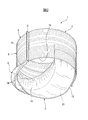
- FIG. 1 is a partially broken perspective view schematically showing an embodiment of the disposable diaper according to the present invention.
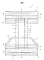
- FIG. 2 is a schematic perspective view seen from a position different from FIG. 1 in the embodiment of the disposable diaper according to the present invention.
- FIG. 3 is a top view which shows typically the state which expand
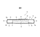
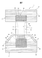
- FIG. 4 is a schematic enlarged end view of an essential part of the absorber. However, the state which cut
- FIG. 5 is a schematic cross-sectional view of an essential part of the absorber at a position different from FIG. 4.
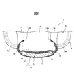
- FIG. 6 is a schematic enlarged cross-sectional view of the disposable diaper of FIG. 1 cut at the center of the crotch sheet member in the lengthwise direction of the crotch sheet member.
- FIG. 7 shows a state in which the first adhesive application region in the first bonding portion and the second adhesive application region in the second bonding portion are intersected and joined in the expanded state of the disposable diaper of FIG. 1 Is a figure which shows typically.
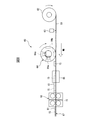
- FIG. 8 is a schematic view of an apparatus for forming a continuous body of an absorbent.
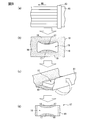
- FIG. 9 is a view schematically showing each step of forming a continuum of the absorber.
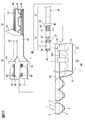
- FIG. 10 is a view for explaining steps of manufacturing the disposable diaper according to the present invention.
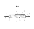
- FIG. 11 is a schematic enlarged sectional view of an essential part showing an absorber different from that of FIG. However, the state which cut
- FIGS. 1 to 7 show an embodiment of the absorbent article of the present invention, and in this embodiment, the case where the absorbent article is a disposable diaper will be described.
- the disposable diaper 1 of this embodiment is a so-called three-piece type consisting of three substantially rectangular sheet members mainly covering the ventral side, the dorsal side and the crotch of the wearer.
- the disposable diaper 1 has a crotch sheet member 2 long in one direction covering the crotch region of the wearer, and the crotch sheet member 2 superimposed on one end side of the crotch sheet member 2 in the lengthwise direction.
- a ventral side sheet member 3 for covering the ventral side of the wearer.
- the back of the wearer is joined to the other end side in the lengthwise direction of the crotch sheet member 2 in a state of being superimposed on the crotch sheet member 2 as a separate member from the belly sheet member 3.
- the back side sheet member 4 which covers the side is provided.
- the crotch sheet member 2, the belly sheet member 3 and the back sheet member 4 are mutually joined by an adhesive at a portion where they are superimposed.
- the disposable diaper 1 is a so-called pants type in which the ventral sheet member 3 and the back sheet member 4 are joined by various means such as fusion.
- a waist opening 1a is formed on the upper side in the wearing (standing position) by the belly side sheet member 3 and the back side sheet member 4, and the belly side sheet member 3 and the lower side
- the back sheet member 4 and the crotch sheet member 2 form a pair of footbore openings 1b, 1b through which the legs of the wearer pass.
- the crotch sheet member 2 is formed in a generally rectangular shape in a plan view extending from the abdominal side sheet member 3 to the back side sheet member 4 through the lower side of the crotch of the wearer.
- the crotch sheet member 2 is a liquid-permeable liquid-permeable sheet 11 (so-called top sheet) located on the skin surface side of the wearer and extending in the lengthwise direction of the crotch sheet member 2;
- a liquid impermeable sheet 12 (so-called back sheet) having liquid impermeability is provided, which is located on the side opposite to the skin surface side of the person and extends in the longitudinal direction of the crotch sheet member 2.
- the crotch sheet member 2 is disposed between the liquid-permeable sheet 11 and the liquid-impermeable sheet 12 and absorbs and holds waste fluid such as urine excreted from the wearer. It comprises an absorbent body 13 extending long in the longitudinal direction of the crotch sheet member 2, and a pair of leakage preventing walls 14 and 14 extending in the longitudinal direction of the crotch sheet member 2 along the absorbent body 13. .
- the liquid impermeable sheet 12, the belly sheet member 3 and the back sheet member 4 are adhered to each other in portions of the crotch sheet member 2, the belly sheet member 3 and the back sheet member 4 which are overlapped. It is directly joined by the agent.
- the liquid-permeable sheet 11 is in contact with the skin of the wearer, absorbs the urine of the wearer quickly, and is transferred to the absorber 13, and is unidirectional, specifically, the length direction of the absorber 13 Long and generally larger than the absorber 13 in plan view and generally rectangular, and mutually joined with the absorber 13 by any bonding means such as adhesion using a hot melt adhesive. .
- the liquid impermeable sheet 12 prevents permeation of the excreted excrement fluid to prevent the excrement fluid from leaking to the outside, and any bonding such as adhesion with a hot-melt adhesive can be performed.
- the absorber 13 and the liquid-permeable sheet 11 are mutually joined by means.
- the liquid-impervious sheet 12 is formed in a substantially rectangular shape in plan view, which is longer in one direction, specifically, in the longitudinal direction of the absorber 13 and which is larger than the absorber 13 as a whole,
- the absorbent body 13 and the liquid-permeable sheet 11 are mutually bonded by an arbitrary bonding means such as adhesion with an adhesive.
- the absorbent body 13 has an absorbent core 15 which substantially absorbs and holds waste fluid, and a liquid-permeable covering sheet 16 which covers the outer surface of the absorbent core 15.
- the covering sheet 16 has a sheet surface having a substantially rectangular shape in plan view at the time of deployment, and the outer peripheral surface of the absorbent core 15 (a liquid permeable sheet side and a liquid impermeable sheet side of the absorbent core, and the absorbent core
- the entire surface of the outer peripheral surface of the absorbent core 15 can be surrounded around the longitudinal axis of the absorbent core 15 with respect to the surface on both end sides in the width direction of 15 and wound around the absorbent core 15 In this case, the length of the absorbent core 15 in the longitudinal direction is sufficiently longer than the length of the absorbent core 15 in the longitudinal direction.
- the covering sheet 16 is formed of, for example, a tissue or the like mainly made of crushed pulp and formed by a wet method.
- the absorbent core 15 includes a water absorbing material such as pulp and a highly absorbent material such as a water absorbing polymer, and the back side of the abdominal sheet member 3 passes through the lower side of the crotch of the wearer. It extends in the direction of the side sheet member 4 side, that is, along the length direction of the crotch part sheet member 2 and is formed in a band shape having a certain thickness.
- the absorbent core 15 is provided on both ends in the width direction of the absorbent core 15 so that the absorbent body 13 can be easily fitted to the base of the wearer's thighs.
- the footbore portions 17 and 17 are formed so as to be convex toward the center side in the width direction of the absorbent core 15, respectively.
- the foot portions 17, 17 are formed such that the central portion in the lengthwise direction of the absorbent core 15 is the apex of the curved portion.
- the absorbent core 15 when the absorbent core 15 is viewed from the liquid-permeable sheet 11 side (hereinafter referred to as "planar view"), the absorbent core 15 has a shape in which the central portion in the longitudinal direction is narrowestly narrow (so-called It has an hourglass shape). Moreover, the four corners of the absorption core 15 in plan view are chamfered to form a curved surface.
- the water absorbing material forming the absorbent core for example, wood pulp obtained from softwood or hardwood as raw material, mercerized pulp or crosslinked pulp, non-wood pulp, regenerated cellulose such as rayon, acetate, etc. Semi-synthetic cellulose etc. are mentioned.
- the superabsorbent materials include starch-based, cellulose-based, and synthetic polymer-based superabsorbent materials.
- starch-based or cellulose-based super absorbent materials include starch-acrylic acid (salt) graft copolymers and the like
- examples of synthetic polymer super absorbent materials include, for example, polyacrylate based (especially in particular And sodium polyacrylate based resins (Super absorbent Polymer: SAP).
- the shape of the superabsorbent material include particles, fibers, scaly and the like, and in the case of particles, the particle size is preferably 50 to 1000 ⁇ m, more preferably 100 to 600 ⁇ m. .
- the covering sheet 16 is disposed around the longitudinal axis of the absorbent core 15, that is, the surface of the absorbent core 15 on the liquid permeable sheet 11 side, and the liquid It is wound so as to surround the surface on the side of the permeable sheet 12 and both end sides in the width direction. Further, the surface on the liquid-permeable sheet 11 side and the surface on the liquid-impermeable sheet 12 side of the absorbent core 15 and the cover sheet 16 are respectively adhered by an adhesive, and thereby the absorbent core 15 and The cover sheet 16 is mutually adhered.
- any adhesive can be used as long as it can bond the absorbent core 15 and the covering sheet 16 reliably and stably, but a hot melt adhesive is most preferable.
- the hot melt adhesive include polyolefin-based, ethylene / vinyl acetate copolymer-based, and synthetic rubber-based.
- an acrylic resin adhesive can be used as another adhesive agent.
- the covering sheet 16 has a forehead winding shape with respect to the absorbent core 15, that is, each corner of the maximum width portion W of the absorbent core 15
- the absorbent core 15 is bent along a straight line extending in the longitudinal direction of the absorbent core 15, and is wound on the absorbent core 15 from the liquid impermeable sheet side of the absorbent core 15 to the liquid permeable sheet side. It is rolled. Accordingly, the covering sheet 16 is wound around the absorbent core 15 so as to have a substantially rectangular shape in plan view as a whole of the absorbent 13.
- the covering sheet 16 in a state where the covering sheet 16 is wound around the absorbent core 15, the covering sheet 16 extends from the end in the width direction of the absorbent core 15 and the inner peripheral surface side is the liquid permeable sheet 11 side of the absorbent core 15. And the surface on the liquid-impermeable sheet 12 side are not in contact with each other.
- the covering sheet 16 is wound in a forehead shape around the absorbent core 15 so that the entire absorbent 13 has a substantially rectangular shape in plan view. Because the absorbent core 15 is wound around, the extension portions 18 are formed in the portion where the foot portion 17 of the absorbent core 15 is provided.
- each of the leg portion 17 is curved so as to be convex toward the center side in the width direction of the absorbent core 15.
- the covering sheet 16 extends outward in the width direction of the absorbent body 13 from the leg counters 17, 17 at the portion where the leg counters 17, 17 are provided, and the inner periphery
- the extended part which each surface side does not contact mutually with the surface by the side of the liquid-permeable sheet 11 in the absorption core 15 and the surface by the side of the liquid-impermeable sheet 12 is formed respectively, the extended part of these Are the extension portions 18, 18.
- the extension portion 18 is not bonded to the absorbent core 15 so that the movement of the absorbent core 15 is not restricted.
- the inner peripheral surface side of the extension portion 18 basically does not contact the absorption core 15, and a hollow space is formed. Is formed.
- an absorbent material 19 having a liquid absorbing property and separate from the absorbent core 15 is made It is glued.
- the absorbent material 19 is a material similar to the water absorbent material or the superabsorbent material used for the absorbent core 15, and the SAP is particularly preferable.
- the absorbent material 19 may be pulp, or both of SAP and pulp.
- the adhesive is the same as the adhesive for bonding the absorbent core 15 and the cover sheet 16 to each other, and a hot melt adhesive is most preferable.
- the absorbent material 19 is basically adhered to the entire inner peripheral surface of the extending portions 18. Therefore, when the disposable diaper 1 is worn (when the wearer is in the standing position), the absorbent material 19 is a region facing upward on the inner peripheral surface side of the extension portions 18, ie, the extension portion It is adhered to the area on the liquid impervious sheet 12 side on the inner peripheral surface side of the side walls 18 and 18. Similarly, it is adhered also to the downward facing area on the inner peripheral surface side of the extension parts 18 and 18, that is, the area on the liquid permeable sheet 11 side on the inner peripheral surface side of the extension parts 18 and 18 There is.
- the absorbent 13 always has the absorbent material 19 in the portion of the liquid-permeable sheet 11 in contact with the covering sheet 16, so the wearer wearing the disposable diaper 1 can use the disposable diaper In the case where sweating occurs in 1 and the humidity rises, the absorbent material 19 can quickly absorb moisture such as sweat contained in the liquid-permeable sheet 11 and the covering sheet 16. Therefore, the liquid-permeable sheet 11 can be maintained in a dry state, and the wet state can be suppressed with respect to the environment in the disposable diaper 1.
- the covering sheet 16 has an overlapping portion 20 extending in the longitudinal direction of the absorbent body 13 mutually connected by an adhesive in a state in which both end portions in the winding direction around the absorbent core 15 are overlapped. doing.
- the overlapping portion 20 is fixed to the side of the liquid-permeable sheet 11 in the absorbent core 15.
- the absorbent material 19 is disposed between the one end side and the other end side of the covering sheet 16 constituting the overlapping portion 20 in the winding direction of the absorbent core 15. It is done.
- the covering sheet 16 is bent along the surface of the absorbent core 15 on the liquid-permeable sheet 11 side in the winding direction of the absorbent core 15, and the liquid-permeable sheet
- the overlapping portion 20 is formed by being superimposed on the surface on the side 11.
- the absorbent material 19 is adhered in the overlapping portion 20, that is, between one end side and the other end side of the covering sheet 16 in the winding direction around the absorbent core 15 which forms the overlapping portion 20. It is made to intervene in the state.
- the overlapping portion 20 is located substantially at the center in the width direction of the absorbent core 15 on the liquid-permeable sheet 11 side of the absorbent core 15.
- the overlapping portion 20 is disposed on the liquid-permeable sheet 11 side in the absorbent core 15 and the absorbent material 19 is disposed in the overlapping portion 20 because the disposable diaper 1 is worn.
- the purpose is to efficiently absorb the sweat which the wearer wears in the buttocks by the absorbent material 19.
- the disposable diaper since the wearer wearing the disposable diaper is likely to sweat at the central part (tear and tear part) in the width direction of the buttocks, the disposable diaper is the part covering the buttocks of the wearer. It is desirable to increase the ability to absorb liquid at the part corresponding to the burst part.
- the absorbent material is disposed in the overlapping portion 20.
- the overlapping portion 20 is located substantially at the center in the width direction of the absorbent core 15 on the liquid-permeable sheet 11 side of the absorbent core 15, and therefore, it is more stable and effective. It is possible to absorb the sweat of the groin area.
- the pair of leak-proof walls 14, 14 rise toward the surface of the liquid-permeable sheet 11 opposite to the absorbent body 13 when worn, that is, toward the skin surface of the wearer, and the tip end is the wearer's
- the contact with the skin surface is intended to prevent the excrement fluid from leaking out from between the skin surface of the wearer and the crotch sheet member 2.
- the pair of leak-proof walls 14 have hydrophobicity or water repellency so as to prevent leakage of the excretory fluid, for example, by a material such as a spunbond nonwoven, an SMS nonwoven, an air through nonwoven, etc. It can be configured.
- elastic members 14a and 14a for leakproof walls are disposed on the upper end side of the leakproof walls 14 and 14 and extend in the length direction of the respective leakproof walls 14 and 14
- Each of the leakproof walls 14 and 14 is elastically raised, and the leakproof walls 14 and 14 easily adhere to the skin surface of the wearer.
- the proximal end side of the pair of leak preventing walls 14, 14 in the raised state is on the outer side in the width direction of the crotch sheet member 2 than the positions of both end portions in the width direction of the absorber 13. It is placed in position.
- the position corresponding to the portion located most on the center side in the width direction of the absorber 13 can stand up according to the shape of the inner crotch of the wearer of the disposable diaper 1.
- the leakproof wall 14 reverses the liquid-permeable sheet 11 to the absorber 13. Is pushed up in the direction of the skin side of the wearer, that is, the skin side of the wearer. Further, at that time, the extending portion 18 is in a state where the space on the inner peripheral surface side of the extending portion 18 is crushed and deformed along the wall surface of the leakage preventing wall 14.
- the extension part 18 becomes a shape along the inner crotch part of the wearer of the disposable diaper 1, the inner crotch part which is one of the parts which is easy to sweat in the wearer wearing the disposable diaper 1
- the absorbent material 19 of the extension portion 18 can absorb sweat at the base of the leg and in the vicinity thereof. As a result, the feeling of use of the disposable diaper 1 can be maintained better, and the wet state of the environment in the disposable diaper 1 can be effectively suppressed.
- the covering sheet 16 in the state of being wound around the absorbent core 15, a pair of longitudinal side extension parts 21 and 22 extending respectively from both ends in the longitudinal direction of the absorbent core 15 are formed. It is done.
- the cover sheet 16 is wound on the absorbent core 15 around the longitudinal axis of the absorbent core 15 as described above. At this time, the length of the absorbent core 15 in the longitudinal direction is sufficiently longer than the length of the absorbent core 15 in the longitudinal direction.
- the covering sheet 16 in a state of being wound around the absorbent core 15 protrudes from both ends in the lengthwise direction of the absorbent core 15 in the abdominal sheet member direction and the back sheet member direction in the absorbent core 15.
- An extended portion is formed. Therefore, these extended portions extend on the ventral side sheet member toward the ventral side longitudinal direction extending portion 21 and on the back side extending in the direction of the dorsal sheet member. It becomes the part 22.
- the length direction side extending portion 21 on the belly side and the length direction side extending portion 22 on the back side have substantially the same length in the length direction of the absorbent core 15. It has become.
- the ventral side longitudinal extension 21 and the back longitudinal side extension 22 are respectively free ends of the absorbent core 15 in the longitudinal direction (opposite to the absorbent core 15)
- the end portion located on the (1) side becomes an open state (non-closed state).
- the absorbent body 13 is disposed between the liquid-permeable sheet 11 and the liquid-impermeable sheet 12 so that the liquid-permeable sheet 11 and the liquid-impermeable sheet 12 have their peripheries. When they are joined to each other in the portion, the free end side of the absorbent core 15 in the ventral longitudinal extension 21 and the dorsal longitudinal extension 22 are also joined together. It will be joined and closed.
- the absorbent material 19 having a liquid absorbing property is adhered to the inner peripheral surface side of the pair of longitudinal direction extending portions 21 and 22 by an adhesive.
- the absorbent material 19 is the same as the water absorbent material or the superabsorbent material used for the absorbent core 15, that is, it is adhered to the inner peripheral surface side of the extension part 18. It is similar to the one.
- the adhesive is the same as the adhesive for bonding the absorbent core 15 and the cover sheet 16 to each other, and a hot melt adhesive is most preferable.
- the pair of longitudinal side extension parts 21 and 22 on the ventral side and the back side are formed, and the absorbent material 19 is adhered to the longitudinal side extension parts 21 and 22 on the longitudinal side and the back side, respectively.
- the pair of longitudinal extension parts 21 and 22 can stably keep the environment in the disposable diaper 1 together with the extension part 18 in a dry state, and further, liquid leakage can be made more reliable. It is possible to prevent
- the basis weight of the absorbent material 19 bonded to the inner peripheral surface side of the belly-side length direction side extension portion 21 of the pair of length direction side extension portions 21 and 22 is:
- the length is more than the length-side extension 22 on the back side. This is because, for example, when a male wears the disposable diaper 1, the excretory fluid such as urine is often excreted on the front side of the wearer, that is, on the ventral side. This is because it is preferable to make the absorption capacity of the excretory fluid as high as possible.
- the absorbent body 13 has a higher basis weight, the absorption capacity of the excretory fluid at the end side of the ventral side is higher than that of the dorsal side. As a result, the excretory fluid excreted to the ventral side can be absorbed quickly, and the environment in the disposable diaper 1 can be maintained in a dry state more effectively and stably.
- the belly side sheet member 3 is formed in a substantially rectangular shape extending in a direction along the width direction of the crotch portion sheet member 2, that is, in the left and right direction of the wearer at the time of wearing.
- the length in the longitudinal direction is larger than the length in the width direction of the crotch sheet member 2.
- the belly sheet member 3 includes an inner sheet 26 located on the skin surface side of the wearer and an outer surface located on the opposite side of the skin surface of the wearer, ie, the outer side of the disposable diaper 1 A direction along the width direction of the crotch part sheet member 2 disposed between the side sheet 27 and the inner side sheet 26 and the outer side sheet 27, that is, a straight line in the longitudinal direction of the belly side sheet member 3 And a plurality of ventral elastic members 28 extending in a vertical direction.
- the inner surface side sheet 26 and the outer surface side sheet 27 in the belly side sheet member 3 are formed in the same shape and size as each other by a non-woven fabric or the like excellent in air permeability.
- the inner sheet 26 and the outer sheet 27 can be formed of the same non-woven fabric as the liquid-permeable sheet 11 of the crotch sheet member 2.
- the plurality of abdominal elastic members 28 elastically expand and contract in the axial direction, that is, in the longitudinal direction of the abdominal sheet 3 (the direction along the width direction of the crotch sheet member 2).
- a thread-shaped rubber is used.
- the abdominal elastic members 28 are arranged in the width direction of the abdominal sheet 3 at predetermined intervals, that is, in the longitudinal direction in the wearing (standing position) state, the inner sheet 26 and the outer side It is accommodated between the seat 27 and the seat 27.
- An adhesive is applied to the outer peripheral surface of each abdominal elastic member 28, and each abdominal elastic member 28 is mutually joined with the inner sheet 26 and the outer sheet 27 by this adhesive.
- the back side sheet member 4 extends in a direction perpendicular to the length direction of the crotch part sheet member 2, that is, a substantially rectangular shape extending in the left and right direction of the wearer at the time of wearing.
- the back sheet member 4 is formed in a shape, and the length in the longitudinal direction of the back sheet member 4 is larger than the length in the width direction of the crotch sheet member 2.
- the back side sheet member 4 is an inner side sheet 31 located on the skin surface side of the wearer, and an outer side located on the opposite side to the skin surface of the wearer, that is, the outer side of the disposable diaper 1
- the back side sheet member 4 and the ventral side sheet member 3 are joined to each other at the joint portions 5 at both ends of the back side sheet member 4 and the ventral side sheet member 3 in the longitudinal direction, and are worn. Close to the waist or belly of the person.
- the inner side sheet 31 and the outer side sheet 32 in the back side sheet member 4 are formed in the same shape and size with each other by a non-woven fabric or the like excellent in air permeability.
- the inner side sheet 31 and the outer side sheet 32 are non-woven fabrics similar to the liquid-permeable sheet 11 of the crotch sheet member 2 and the inner side sheet 26 and the outer side sheet 27 of the belly side sheet member 3. It can be formed.
- the plurality of back elastic members extend in a direction along the width direction of the crotch sheet member 2 and elastically expand and contract in the length direction, and in this embodiment, the rubber formed in a thread shape Are used respectively.
- An adhesive is applied to the outer peripheral surface of each back elastic member, and each back elastic member is mutually joined with the inner side sheet 31 and the outer side sheet 32 by this adhesive.
- the length in the width direction (vertical direction when worn (standing position)) of the back side sheet member 4 is formed larger than the length in the width direction of the belly side sheet member 3 When worn, it is configured to be able to cover from around the waist of the wearer to the buttocks.
- the back side sheet member 4 is a base portion 8 joined to the abdominal side sheet member 3 for covering the waist of the wearer, and the length of the crotch portion sheet member 2 than the base portion 8.
- the buttocks covering portion 9 covering the buttocks of the wearer, which is disposed near the central portion in the direction, is integrally formed.
- the base portion 8 is formed in a substantially rectangular shape having substantially the same size and shape as the abdominal side sheet member 3, and a part of the plurality of back elastic members is in the length direction of the back side sheet member 4. That is, it is disposed as a first elastic member 33 extending in the longitudinal direction of the base portion 8.
- the first elastic members 33 are arranged at predetermined intervals in the width direction of the base portion 8, that is, in the vertical direction in the wearing (standing position) state, the base portion 8 in the back side sheet member 4 Between the inner side sheet 31 and the outer side sheet 32 located in the range of (1).
- the same number of first elastic members 33 are provided at the same intervals as the abdominal elastic members 28 of the abdominal sheet member 3.
- the buttocks-covering portion 9 is an edge portion on the central side in the lengthwise direction of the crotch sheet member 2 in the width direction of the back side sheet member 4 (vertical direction when worn (standing position))
- the lower end of the portion (9), that is, the lower end of the crotch sheet member 2 in the wearing (standing position) direction is the middle side in the lengthwise direction of the crotch sheet member 2 It is configured to project so as to be convex toward the
- the edge portion 9a of the buttocks covering portion 9 the central portion in the longitudinal direction of the back side sheet member 4, that is, the central portion in the longitudinal direction of the portion projected to be convex.
- the portion is a linear portion extending substantially linearly in the same direction as the longitudinal direction of the buttock covering portion 9.
- a portion other than the linear portion is a curved portion which curves gently.
- a back elastic member other than the first elastic member 33 disposed on the base portion 8 corresponds to the crotch portion in the buttock covering portion 9.
- a second elastic member 34 is disposed at the edge portion 9 a on the center side in the longitudinal direction of the sheet member 2.
- the second elastic member 34 extends in the lengthwise direction of the back side sheet member 4 along the edge portion 9a on the central side in the lengthwise direction of the crotch portion sheet member 2 in the buttocks covering portion 9 and It is elastically expandable in the axial direction.
- the second elastic member 34 is disposed along the edge portion 9 a of the buttocks covering portion 9 as a whole, while both end sides are in the longitudinal direction of the base portion 8.
- the first elastic member 33 and the second elastic member 34 are positioned on the end side in the longitudinal direction of the back side sheet member 4.
- a part on the end side in the axial direction is fixed to the inner side sheet 31 and the outer side sheet 32 forming the back side sheet member 4 in a state where they cross each other. That is, both end sides of the second elastic member 34 are in a state in which the part which has penetrated into the base portion intersects with a part of the first elastic member 33 disposed in the base portion 8. It has become.
- the first elastic member 33 and the second elastic member 34 are partially located on the end side in the axial direction of the back side sheet member 4 in the longitudinal direction.
- the first elastic member 33 and the second elastic member 34 cooperate with each other to move the crotch sheet member upward It is for pulling up and fitting the crotch part sheet member 2 to a wearing part of a wearer.
- the end portions of the two first elastic members 33, 33 located on the buttocks covering portion 9 side (the lower side of the base portion 8 in the wearing (standing position)) in the base portion 8 The end portions of the three second elastic members 34 are fixed in a state where they cross each other at the joint portion 5.
- the intersection of the first elastic member and the second elastic member is located at the joint portion.
- the axial direction of each of the first elastic member and the second elastic member It also includes a state in which a part of the end side reaches the closest junction while maintaining the state of crossing each other.
- a part of the belly-side elastic member 28 is a belly-side length-direction extension of the pair of length-direction extension parts 21 and 22 in the covering sheet 16. It is arrange
- a part of the back elastic member is disposed so as to overlap with a position corresponding to the back side longitudinal extension 22 in the covering sheet 16.
- some of the plurality of first elastic members 33 disposed in the base portion 8 of the back side sheet member 4 among the back side elastic members are the length of the back side. It is disposed to overlap with the position corresponding to the longitudinal extension 22.
- the ventral elastic member 28 or the dorsal elastic member overlaps the position corresponding to the ventral longitudinal extension 21 or the dorsal longitudinal extension 22. It is arranged for the following reasons. That is, the elastic force of the abdominal elastic member 28 and the dorsal elastic member causes the longitudinal extension 21 on the abdominal side and the longitudinal extension 22 on the back in the width direction of the absorber 13. By contracting the absorbent material 19 bonded to the inner peripheral surface side of the longitudinal side extension parts 21 and 22 as much as possible, the longitudinal side extension part 21 is contracted. , 22 in order to improve the absorption capacity of the liquid as much as possible.
- ventral side longitudinal extension portion 21 and the back longitudinal side extension portion 22 are contracted in the width direction of the absorber 13 by the elastic force of the ventral elastic member 28 and the dorsal elastic member ( When viewed from the liquid-permeable sheet side in plan view (in this embodiment, the flexing side) and the ventral side longitudinal extension 21 and the back longitudinal side extension 22
- the density of the region where the absorbent material 19 is present is increased, the ability of the pair of longitudinal extension parts 21 and 22 to absorb liquid can be increased.
- the portion in which the liquid impermeable sheet 12 and the abdominal sheet member 3 or the back sheet member 4 are superposed and abutted against each other are mutually joined.
- known joining means may be used for joining the liquid impermeable sheet 12 on the both end sides of the crotch sheet members 2 in the longitudinal direction, and the abdominal sheet member 3 and the back sheet member 4. Although this can be done, in this embodiment, they are joined to each other by adhesion with an adhesive.
- the liquid impermeable sheet 12 of the crotch sheet member 2 the liquid impermeable sheet 12 is in contact with the belly sheet member 3 and the back sheet member 4.
- the first adhesive portion 36 is in contact with the back side sheet member 4 in the portion, that is, both end sides of the liquid impervious sheet 12 in the lengthwise direction, more specifically, the portion in contact with the ventilated
- the first adhesive 37 is formed on the portions in contact with each other.
- a second bonding portion 38 is formed at a portion of the abdominal side sheet member 3 in contact with one end side of the liquid impermeable sheet 12 in the longitudinal direction
- a second bonding portion 39 is formed in a portion in contact with the other end side in the longitudinal direction 12.
- the first adhesive portions 36 and 37 are disposed on the center side in the width direction of the liquid impermeable sheet 12 in the crotch sheet member 2. Further, in the first adhesive portion 36 formed on the end side to be joined to the abdominal side sheet member 3, an end portion to which a first adhesive application region 40 is joined to the abdominal side sheet member 3 A first adhesive application area 41 is provided in each of the first adhesive portions 37 formed on the side. In this embodiment, the first adhesive portions 36 and 37 are provided such that the first adhesive application regions 40 and 41 extend in the longitudinal direction of the crotch sheet member 2.
- the second adhesive portions 38 and 39 are the liquid-impervious sheets 12 of the crotch sheet member 2 in the inner side sheet 26 of the abdominal side sheet member 3 and the inner side sheet 31 of the back side sheet member 4. And, more specifically, at a position overlapping the first adhesive portions 36 and 37 provided on the liquid impermeable sheet 12.
- the second adhesive portion 38 provided on the belly side sheet member 3 continuously extends in the width direction of the crotch portion sheet member 2, that is, in the length direction of the belly side sheet member 3.
- a second adhesive application area 43 is provided which extends.
- the second adhesive portion 39 provided on the back side sheet member 4 extends continuously in the width direction of the crotch part sheet member 2, that is, in the length direction of the back side sheet member 4.
- a second adhesive application area 44 is provided. Any adhesive can be used as the adhesive applied to the first adhesive application areas 40 and 41 and the second adhesive application areas 43 and 44, but a hot melt adhesive is most preferable.
- the crotch part sheet member 2 (more specifically, the liquid impermeable sheet 12) and the belly side sheet member 3, and the crotch part sheet member 2 (more specifically, the liquid impermeable sheet 12) and the back side sheet
- the member 4 intersects the first adhesive application regions 40 and 41 in the first adhesive portions 36 and 37 and the second adhesive application regions 43 and 44 in the second adhesive portions 38 and 39. They are mutually joined in the state where they are allowed to move. Therefore, with the adhesive applied to the first adhesive application areas 40 and 41 and the adhesive applied to the second adhesive applied areas 43 and 44 also crossing each other, the first adhesion is performed.
- the agent application areas 40 and 41 are in contact with the second adhesive parts 38 and 39, and the second adhesive application areas 43 and 44 are in contact with the first adhesive parts 36 and 37, and they are mutually bonded by the respective adhesives.
- the Rukoto thus, the crotch sheet member 2 is pulled up by the first adhesive application areas 40 and 41 continuous in the lengthwise direction of the crotch sheet member 2 and held so as not to hang down as much as possible.
- the downward tensile force acting on the first adhesive application areas 40 and 41 is the crotch. It becomes possible to disperse in the width direction of the sheet member 2.
- the first adhesive application regions 40 and 41 and the second adhesive application regions 43 and 44 cooperate with each other.
- step S3 of forming the crotch sheet member and the first bonding portion from the laminate for the crotch sheet member, and the second composite member for the abdominal side sheet member and the composite member for the back side sheet member A step S4 of forming an adhesive portion and a step S5 of joining the crotch sheet members and the composite member for the abdominal sheet member and the composite member for the back sheet member are performed. Furthermore, the step S6 of cutting the composite member for the back side sheet member in accordance with the predetermined shape of the buttocks covering portion of the back side sheet member 4 of the disposable diaper 1 is performed.
- the step S1 of forming a laminate for the crotch sheet member will be described. That is, in this step S1, a step of forming a continuum of the absorber, and a liquid-permeable sheet, a liquid-impermeable sheet, the absorber, and a pair of leak-barrier walls constituting the crotch sheet member 2 And performing a laminating step of laminating.
- the continuum 67 of the absorbent is formed using an apparatus 60 as shown in FIG.
- the continuous body 67 of the absorber formed in this process is a plurality of absorbers in a state in which the nonwoven fabric 61 for a long covering sheet to be the covering sheet of the absorber is wound around a plurality of the absorbent cores 5 In the series, that is, a long one before being cut into a single absorbent body 13.
- the device 60 applies an adhesive to the non-woven fabric roll 62 wound with the long non-woven fabric 61 for the coating sheet and the non-woven fabric 61 for the coating sheet drawn from the non-woven fabric roll 62 onto the conveying line.
- An apparatus 63 and a suction drum 64 for molding the absorbent core 15 and placing the molded absorbent core 15 on the nonwoven fabric 61 for the covering sheet are provided. Further, a bending device (sailor) 65 for bending the nonwoven fabric 61 for the covering sheet on which the absorbent core 15 is placed, the nonwoven fabric 61 for the covering sheet bent by the bending device 65 and the absorbent core 15 are absorbed. And a pressing device 66 for pressing in the thickness direction of the core 15.
- the said coating device 63 is applied to the upper surface of the nonwoven fabric 61 for covering sheets on the conveyance line.
- the application process which applies an adhesive agent by this is performed.
- the absorption core 15 is mounted after the mounting step of mounting the absorbent core 15 by the suction drum 64 and after the mounting step.
- a bending step of bending the non-woven fabric 61 for the covering sheet by the bending device 65 is performed on the non-woven fabric 61 for a covering sheet whose upper surface is coated with an adhesive in the application step.
- the continuous process 67 of the absorber is formed by performing the pressing process of pressing the nonwoven fabric 61 for the covering sheet and the absorbent core 15 bent in the bending process with the pressing device 66 in the thickness direction of the absorbent core 15. Then, the continuous body 67 of the absorbent is transported to the subsequent laminating process.
- the application device 63 is a hot member over the entire width (the length in the horizontal direction orthogonal to the conveyance direction) of the nonwoven fabric 61 for the covering sheet on the conveyance line.
- Apply the adhesive such as melt adhesive.
- the adhesive is continuously applied to the upper surface of the non-woven fabric 61 for the covering sheet along the conveying direction of the non-woven fabric 61 for the covering sheet.
- the said adhesive agent can be apply
- a plurality of nozzles capable of discharging the adhesive with a predetermined width are disposed in the width direction of the non-woven fabric 61 for the covering sheet, and the plurality of nozzles provide the entire width of the non-woven fabric 61 for the covering sheet.
- coats an adhesive agent can be used.
- the water absorbing material or the highly absorbent material constituting the absorbent core 15 is provided on the outer peripheral surface of the suction drum 64 on the upper side of the suction drum 64. Further, suction and lamination are performed in a concave mold 64a having a predetermined shape, thereby forming the absorbent core 15 in the mold 64a.
- the suction core 64 in the mold 64 a moves to the lower side of the suction drum 64 with the rotation of the suction drum 64, but when facing the upper surface of the nonwoven fabric 61 for the covering sheet, the suction drum
- the absorbent core 15 in the mold 64a is released from the mold 64a, transferred onto the nonwoven fabric 61 for the covering sheet, and placed.
- the said suction drum 64 is equipped with the type
- the arrows marked on the suction drum 64 in FIG. 8 indicate the suction direction.
- the absorbent core 15 when the absorbent core 15 is placed on the upper surface of the nonwoven fabric 61 for the covering sheet, the water absorption that constitutes the absorbent core 15 is due to an impact or the like at the time of the placement. A part of the porous material or the superabsorbent material is separated from the absorbent core 15 and falls onto the non-woven fabric 61 for the covering sheet. Then, the dropped water absorbing material and highly absorbent material are adhered to the nonwoven fabric 61 for the covering sheet by the adhesive on the upper surface of the nonwoven fabric 61 for the covering sheet. The dropped water absorbing material and highly absorbent material become a part of the absorbing material 19 of the extending portions 18 and 18 and the longitudinal side extending portions 21 and 22.
- the water absorbing material and the highly absorbent material dropped onto the non-woven fabric 61 for the covering sheet basically have the full width of the non-woven fabric 61 for the covering sheet and a constant width on both ends of the absorbent core 15 in the longitudinal direction. It spreads over the range.
- the absorbent core 15 is closer to the absorbent core 15, the basis weight of the water-absorbing material or the superabsorbent material increases, and as the core is separated from the absorbent core 15, the basis weight tends to gradually decrease.
- the water absorbing material and the highly absorbent material are easily removed from the surfaces on both ends in the width direction of the absorbent core 14.
- the surface on both ends in the width direction of the absorbent core 14 has a larger area than the surfaces on both ends in the length direction of the absorbent core 14, and the basis weight with which the water absorbing material and the highly absorbent material fall off is relatively large. Since the amount is large, the basis weight of the absorbent material 19 adhered to the inner peripheral surface tends to be larger than that of the lengthwise extension parts 21 and 22.
- the suction core 64 is rotated to move the absorbent core 15 in the mold 64 a to the lower side of the suction drum 64 as described above. Even when the motor rotates, a part of the water absorbent material and the highly absorbent material constituting the absorbent core 15 fall out of the mold 64 a of the suction drum 64. At that time, the dropped water absorbing material and highly absorbent material fall onto the upper surface of the nonwoven fabric 61 for the covering sheet, and the adhesive on the upper surface of the nonwoven fabric 61 for the covering sheet forms the nonwoven fabric 61 for the covering sheet. Be glued. The dropped water absorbing material and the highly absorbent material also become part of the absorbent material 19 of the extending portions 18 and 18 and the longitudinal side extending portions 21 and 22.
- the absorbent material or highly absorbent material which falls off from the absorbent core 15 in the mold 64 a of the suction drum 64 with the rotation of the suction drum 64 has the mold 64 a as the suction drum 64 rotates. It falls mainly between a position inclined about 90 degrees and a position facing the upper surface of the nonwoven fabric 61 for the covering sheet. Therefore, on the upper surface of the non-woven fabric 61 for the covering sheet on the conveyance line, there are many opportunities for the water absorbing material and the highly absorbent material to fall to the downstream side in the conveyance direction than the position where the absorbent core 15 is placed.
- the absorbent core 15 Because the time for which the absorbent core 15 can be dropped is long, a large amount of the water absorbing material and the highly absorbent material are dropped to the downstream side in the transport direction than the position where the absorbent core 15 is placed. Conversely, on the upstream side in the transport direction with respect to the position where the absorbent core 15 is placed, there is less opportunity for the water-absorbent material or the highly absorbent material to fall compared to the downstream side (the time for which it can fall is short) Therefore, the basis weight of the falling water absorbing material and the high absorbent material is smaller than that of the downstream side.
- the laminate 45 for the crotch sheet member is When a pair of longitudinal direction extension parts are formed in the covering sheet 16 by cutting into one crotch sheet member 2, the basis weight of the absorbent material adhered to the covering sheet 16 is larger
- the length direction side extension part be the belly side length direction side extension part 21 located on the belly side sheet member side.
- the lengthwise direction extension of the absorbent material 19 having a smaller basis weight is taken as the back lengthwise extension 22 located on the back sheet side.
- the covering sheet 16 of the absorbent body 13 is made of the absorbent material 19 bonded to the inner peripheral surface side, of the pair of longitudinal direction extending portions, the belly side longitudinal direction extending portion 21.
- the basis weight can be configured to be larger than that of the back side lengthwise extension 22.
- the non-woven fabric 61 for the covering sheet on which the absorbent core 15 is placed by the bending device 65 having various known configurations the non-woven fabric 61 around the axis of the outer peripheral surface of the absorbent core 15 Bend it so that it is wound in a forehead wrap.
- the non-woven fabric 61 for the covering sheet is extended in the lengthwise direction of the absorbent core 15 at each corner 15a of the maximum width portion W of the absorbent core 15. Bend along a straight line.
- both end portions in the width direction of the non-woven fabric 61 for the covering sheet are overlapped at the center portion in the width direction of the absorbent core 15 on the upper surface side of the absorbent core 15 by the adhesive applied in the application step. Glue and connect to each other. As a result, a portion corresponding to the overlapping portion 20 of the covering sheet 16 is formed.
- the width direction of the non-woven fabric 61 for the covering sheet In the portion where the both end portions are overlapped, the absorbent material 19 is disposed between the one end side and the other end side in the width direction of the nonwoven fabric 61 for the covering sheet.
- the extending portions 18, 18 are formed in the parts of the leg portions 17, 17. That is, the non-woven fabric 61 for the covering sheet extends from the end portion in the width direction of the absorbent core 15 to the portion of the leg portion 17, 17 in the state of being wound around the absorbent core 15.
- the extended portions 18 and 18 which are not in contact with the surface on the liquid-permeable sheet side and the surface on the liquid-impermeable sheet side of the absorbent core 15 are formed.
- the absorbent material 19 which is a water absorbent material or a highly absorbent material which has fallen off from the absorbent core 15 is adhered.
- the water absorbing material and the highly absorbent material in the absorbent core 15 may fall off during this bending step, and even if it is the water absorbent material and the highly absorbent material which has already come off, the covering sheet Some are not completely bonded to the non-woven fabric 61. Then, the water absorbing material and the highly absorbent material which have not been adhered to the non-woven fabric 61 for the covering sheet are the lower side (liquid-impermeable sheet side) of the absorbent core 15 in the non-woven fabric 61 for the covering sheet.
- the bent portion on the lower side of the absorbent core 15 has a large basis weight of the absorbent material and a high absorbent capacity.
- the bent portion on the lower side of the absorbent core 15 on the inner peripheral surface side of the extension portions 18, 18 is relatively easy to sweat when the disposable diaper 1 is worn, and is at the root of the inner crotch side of the wearer As it is a part, the absorbent material 19 adhered to the lower bent part of the absorbent core 15 can effectively absorb sweat and keep the environment in the diaper 1 more stable and dry. It becomes.
- the nonwoven fabric 61 for the covering sheet is wound in a forehead shape around the axis of the outer peripheral surface of the absorbent core 15 by the pressing device 66 of the absorbent core 15. Press in the thickness direction.
- the shape of the absorbent core 15 is stabilized, and the adhesion between the nonwoven fabric 61 for the covering sheet and the absorbent core 15 and the overlapping of both ends in the width direction of the nonwoven fabric 61 for the covering sheet are realized. Mutual adhesion is performed more reliably.
- An arbitrary configuration can be used as the pressing device 66. For example, a plurality of sets of upper and lower pressing rolls are provided, and the non-woven fabric 61 for the covering sheet and the absorbent core between the pair of pressing rolls The thing of the structure which presses 15 can be used.
- the laminating step is performed.
- a liquid-permeable sheet, a liquid-impermeable sheet, a continuous body 67 of the absorber, and a pair of leakproof walls are laminated to form a laminated body 45 for a long crotch sheet member long in the transport direction.
- the liquid-permeable sheet, the liquid-impermeable sheet, and the pair of leak-proof walls are long ones that are formed long in the transport direction).
- the laminated body 45 for the crotch sheet member is conveyed to the next process, step S3 of forming the crotch sheet member 2 and the first bonding portions 36, 37.
- the layered product 45 for the crotch sheet member is in a state before the individual crotch sheet members 2 are formed, in which the plurality of crotch sheet members 2 are substantially continuous in the length direction, Each crotch sheet member 2 is formed by cutting into a predetermined length in the process.
- step S2 of forming composite members for the ventral sheet member and the back sheet member will be described.
- this step S2 as shown in FIG. 10, while conveying the nonwoven fabric 46 for the long outer surface side sheet forming the outer surface side sheets 27, 32 of the abdominal side sheet member 3 and the back side sheet member 4, A plurality of lengths extending in the length direction of the nonwoven fabric 46 for the outer surface side sheet on the nonwoven fabric 46 for the outer surface side sheet, and expanded and contracted from its natural length to a predetermined magnification in the length direction (axial direction).
- Measured elastic members 47 to 49 are disposed at predetermined intervals.
- the composite member 50 for the abdominal sheet member is the abdominal sheet member 3 in the disposable diaper 1 as a finished product
- the composite member 51 for the back sheet member is the back sheet member of the disposable diaper 1. 4 are respectively formed.
- the abdominal side sheet member 3 A long composite member 53 extending in the transport direction is formed by laminating a long non-woven fabric 52 for the inner side sheet that forms the inner side sheets 26 and 31 of the back side sheet member 4.
- the composite member 53 is a combination of the composite member 50 for the abdominal side sheet member and the composite member 51 for the back side sheet member.
- the elastic member 48 and the second elastic member 49 for the back side sheet member disposed at the position corresponding to the buttocks covering portion 9 are different in the method of arranging the nonwoven fabric 46 for the outer surface side sheet. That is, for the first back side sheet member elastic member 48, the plurality of elongated front side sheet member elastic members 47 disposed at positions corresponding to the composite member 50 for the front side sheet member It arrange
- the second elastic member 49 for the back side sheet member has a shape of a predetermined edge portion 9 a of the buttocks covering portion 9, that is, a convex toward the center side in the length direction of the crotch portion sheet member. It arranges on the nonwoven fabric 46 for the above-mentioned sheet by the side of the outside, making it curve according to the shape made to project.
- the first elastic member 48 for the back side sheet member is the first elastic member 33 of the back side elastic members provided on the back side sheet member 4 in the disposable diaper 1 as the finished product
- the second elastic member 49 for the back sheet member is the second elastic member 34 of the back elastic members provided on the back sheet member 4 of the disposable diaper 1.
- the composite member 53 is cut and divided into two by the cutter 55 at a predetermined position in the width direction of the composite member 53,
- the composite member 50 for the ventral side sheet member and the composite member 51 for the back side sheet member at this stage are respectively the ventral side sheet member 3 and the back side sheet member 4 of the disposable diaper 1 as a finished product. It is a thing of the state which became plural and will be divided
- the conveying direction MD of the composite member 50 for the abdominal sheet member and the composite member 51 for the back sheet member is the length direction of each of the abdominal sheet member 3 and the back sheet member 4.
- the step S3 of forming the crotch sheet member 2 and the first adhesive portion 36, 37 from the laminate 45 for the crotch sheet member is performed. .
- the adhesive application device 56 applies various adhesives such as a hot melt adhesive to the liquid impermeable sheet in the laminate 45 for the crotch sheet member conveyed.
- the first bonding portions 36 and 37 are formed by coating.
- the adhesive is applied to a portion corresponding to both end sides of the liquid impermeable sheet 12 in the crotch sheet member 2 and in contact with the ventral sheet member 3 and the back sheet member 4 in a state of overlapping. .
- a first adhesive application region 40, 41 continuous in the longitudinal direction of the liquid impermeable sheet 12 in the crotch sheet member 2 is provided.
- the laminated body 45 for the crotch sheet member is conveyed with the liquid impermeable sheet side positioned on the upper surface for convenience of manufacture, and therefore, the adhesive is not particularly limited. It apply
- the layered product 45 for the crotch sheet member is cut into individual crotch sheet members 2 later, but in this embodiment, when the adhesive 41 is applied, in the transport direction MD, A position on the tail end side of a portion corresponding to the leading crotch sheet member 2 and a leading end side of a portion corresponding to the subsequent crotch sheet member 2 adjacent to the portion corresponding to the leading crotch sheet member 2 At the same time, the adhesive is applied to the position to form the first bonding portions 36, 37 of the respective crotch sheet members 2, 2.
- application of the adhesive to the layered product 45 for the crotch sheet member takes into account the adhesive 41 at a constant interval in consideration of the length in the lengthwise direction of the crotch sheet member 2 determined in advance.
- the first adhesive application area 41 is applied both at the tail end side of the portion corresponding to the leading crotch sheet member 2 and at the leading end side of the portion corresponding to the subsequent subsequent crotch sheet member 2.
- 40 are provided, and in the case of FIG. 9, the first adhesive portion 37 on the tail end side of the portion corresponding to the leading crotch sheet member 2 and the subsequent The first adhesive portion 36) is simultaneously formed on the tip side of the portion corresponding to.
- the first adhesive application regions 40 and 41 are arranged in the width direction of the layered product 45 for the crotch sheet member.
- a plurality is formed in the longitudinal direction of the laminate 45 for the crotch sheet member, that is, in the longitudinal direction of the portion corresponding to the crotch sheet member 2.
- the laminate 45 for the crotch sheet member is sequentially cut into a predetermined length, and one absorbent core 15 is included, Individual crotch sheet members 2 are sequentially formed. At this time, the first adhesive portions 36 and 37 are formed on both end sides of the crotch sheet member 2 respectively. Further, when the laminate 45 for the crotch sheet member is cut, the non-woven fabric 61 for the covering sheet in a state in which the outer peripheral surface of the absorbent core 15 is wound is cut from both ends in the length direction of the absorbent core 15. The absorbent core 15 is cut at a fixed length in the lengthwise direction. As a result, the pair of longitudinal direction extending portions 21 and 22 are formed on the covering sheet 16.
- the water-absorbent material and the height of the absorbent core 15 which are dropped from the absorbent core 15 in the step S1 of forming the laminate for the crotch sheet member The absorbent material 19 which is an absorbent material is already in a state of being adhered by the adhesive.
- the non-woven fabric 61 for the covering sheet is cut so as to have substantially the same length as the length direction of the crotch sheet member 2, and the pair of longitudinal side extensions Among the portions, one having a large amount of the absorbent material adhered to the inner peripheral surface side is the belly-side lengthwise extension 21 and the other is the back-side lengthwise extension 22.
- the composite member 50 for the ventral sheet member and the composite member 51 for the back sheet member is formed.
- the composite member 50 for the abdominal side sheet member and the composite member 51 for the back side sheet member ie, the nonwoven fabric 52 for the inner side sheet.
- the second adhesive portions 38 and 39 are formed by applying various adhesives such as a hot melt adhesive by the adhesive application devices 57 and 58.
- the abdominal side sheet member 3 and the back side sheet member are individually made with respect to the composite member 50 for the abdominal side sheet member and the composite member 51 for the back side sheet member.
- the adhesive is applied to the position corresponding to the portion in contact with the crotch sheet member 2 in the overlapping state.
- a second adhesive which is continuous in the longitudinal direction (that is, the conveyance direction) of the composite member 50 for the ventral sheet member and the composite member 51 for the back sheet member.
- Application areas 43 and 44 are provided respectively.
- step S5 of joining the crotch sheet member and the composite member for the abdominal sheet member and the composite member for the back sheet member is performed.
- step S5 as shown in FIG. 10, with respect to the composite member 50 for the ventral side sheet member and the composite member 51 for the back side sheet member on which the second bonding portions 38 and 39 are respectively formed,
- the both end portions of the liquid impermeable sheet 12 in the crotch sheet member 2 in which the first bonding portions 36 and 37 are formed are in contact with each other, and the first bonding portions 36 and 37 and the second bonding portion are formed. Close contact with 38 and 39.
- the composite member 50 for the abdominal side sheet member and the composite member 51 for the back side sheet member are conveyed in a state in which a certain distance is maintained, and the crotch sheet member 2 has a length
- the direction is arranged along the sheet surface of the composite member 50 for the ventral sheet member and the composite member 51 for the back sheet member and in a direction substantially orthogonal to the length direction of both the composite members 50 and 51.
- the crotch sheet member 2 since the crotch sheet member 2 is transported in a state in which the liquid impermeable sheet 12 on which the first bonding portions 36 and 37 are formed is positioned on the upper surface side, The crotch part sheet member 2 needs to be brought into contact with the composite member 50 for the abdominal side sheet member and the composite member 51 for the back side sheet member after being turned upside down.
- step S6 of cutting the composite member for the back side sheet member in accordance with a predetermined shape of the buttocks covering portion is performed.
- step S6 as shown in FIG. 10, the shape of the predetermined edge portion 9a of the buttocks covering portion 9 of the disposable diaper 1 as a product, that is, the central side in the lengthwise direction of the crotch sheet member 2 A portion corresponding to the edge portion 9 a of the buttocks covering portion 9 in the composite member 51 for the back side sheet member is cut (legged cut) so as to conform to the shape of projecting toward the convex side.
- the cutting in this process S6 is performed along the said 2nd elastic member 49 for back side sheet members arrange
- step S7 of superposing the composite member for the abdominal sheet member and the composite member for the back sheet member as shown in FIG. 10, the crotch sheet is folded by bending the crotch sheet member 2.
- the composite member 50 for the ventral side sheet member joined to the member 2 and the composite member 51 for the back side sheet member are stacked on each other.
- the step S8 is performed in which the composite member for the abdominal side sheet member and the composite member for the back side sheet member are adhered to each other and cut.
- this step S8 as shown in FIG. 10, the abdominal sheet member 3 and the back sheet member in which the composite member 50 for the abdominal sheet member and the composite member 51 for the back sheet member are stacked in advance.
- bonding is performed with a fixed width by an arbitrary means such as heat sealing or fusion by ultrasonic sealing while leaving a fixed interval. Thereby, the both ends of the longitudinal direction of belly side sheet member 3 and back side sheet member 4 are joined mutually.
- a part of this joined part becomes joint part 5 of each disposable diaper 1 as a finished product.
- a part of the intersection of the first back sheet elastic member 48 and the second back sheet elastic member 49 is a joint between the abdominal sheet 3 and the back sheet 4. It is preferable to be located in the part and its vicinity. Then, the part which joined the composite member 50 for belly side sheet members and the composite member 51 for back side sheet members which were made to overlap was cut so that it might become individual disposable diaper 1, and junction part 5, 5 By forming it, the pants-type disposable diaper 1 is completed.
- the coating sheet 16 wound around the axis line of the length direction of this absorption core 15 on the outer peripheral surface of the said absorption core 15 is the width of the said absorption core 15 Extending from the end of the direction and having the extension portions 18, 18 whose inner peripheral surface side is not in contact with the surface of the absorbent core 15 on the liquid permeable sheet side and the surface of the liquid impermeable sheet side. doing. Therefore, when the absorbent core 15 expands due to absorption of a liquid such as waste fluid, the extension portions 18 and 18 serve as a bulge of the absorbent core 15, so that the expansion of the absorbent core 15 is not inhibited. Thus, the absorbent core 15 can fully exhibit its original absorption power.
- an absorbent material 19 is adhered to the inner peripheral surface side of the extension portions 18 and 18. Therefore, even if the liquid once absorbed from the absorbent core 15 exudes to the extension portions 18, 18, the absorbent material absorbs the liquid again, while the sweat of the wearer of the disposable diaper 1 Even if it adheres to the said extension parts 18 and 18, the absorptive material 19 absorbs. Thereby, it is possible to stably suppress liquid leakage of liquid such as waste liquid of the disposable diaper 1 and steaming at the time of wearing. As a result, the said disposable diaper 1 can ensure simultaneously both the stable absorption power at the time of wear, and the favorable use feeling by liquid leakage and prevention of steaming.
- the absorbent core 15 is provided with leg portions 17 and 17 which are curved on both end sides in the width direction so as to be convex toward the center side in the width direction of the absorbent core 15.
- the covering sheet 16 is wound around the absorbent core 15 in a state of extending outward in the width direction of the absorbent body 13 from the leg counters 17, 17 and the legging in the covering sheet
- the portions extending from the portion are the extending portions 18, 18.
- the absorbent core does not necessarily have to have a foot portion.
- the covering sheet extends from the end in the width direction of the absorbent core, and the inner peripheral surface side is the surface on the liquid-permeable sheet side in the absorbent core and It is only necessary to provide an extension which is not in contact with the surface on the liquid impermeable sheet side.
- a pair of disposable diapers 1 as an absorbent article can be erected on the side of the liquid-permeable sheet opposite to the absorbent body, the pair extending in the lengthwise direction of the absorbent body
- leakage barriers are provided, these leakage barriers do not necessarily have to be provided. Further, even in the case where the pair of leak preventing walls is provided, these pair of leak preventing walls are the most in the foot portion of the absorber (the absorbent core 15) as in the embodiment. It is not necessary to be able to stand up with a position corresponding to the portion located on the center side in the width direction of the absorber as the proximal end, and if leakage of excrement etc. by the wearer can be prevented, the proximal end when standing up The position of can be set arbitrarily.
- the absorbent material 19 is bonded to the entire inner peripheral surface side of the extension portions 18 and 18.
- the absorbent material does not necessarily have to be bonded to the entire inner peripheral surface side of the extension part, and a part of the inner peripheral surface side of the extension part, for example, the liquid impermeable sheet side
- the absorbent material may be adhered only at the position or at the liquid-permeable sheet side.
- the absorbent material is substantially uniformly adhered to the entire inner peripheral surface side of the extending portion.
- it may be bonded in a state of being biased to a part of the inner peripheral surface side of the extension.
- the covering sheet 16 is wound around the absorbent core 15 in a forehead shape, but the wrapping sheet may be wound on the outer peripheral surface of the absorbent core as to how to wind the covering sheet on the absorbent core. It can be wound in any manner as long as it is wound around the longitudinal axis of the absorbent core and the extension part is formed. Furthermore, even when the covering sheet is wound around the absorbent core in a forehead shape, it is not necessary to bend the corners of the maximum width part of the absorbent core as in the embodiment, and the extension As long as the portion is formed, it may be bent along a straight line extending in the longitudinal direction of the absorbent core at any position.
- the extension portions 18, 18 are in a mode in which a space is formed on the inner peripheral surface side, and are deformed along with the rising of the pair of the leak preventing walls 14, 14. It has become a thing.
- the extension portion extends from the end in the width direction of the absorbent core, and the inner peripheral surface side mutually interacts with the surface of the absorbent core on the liquid permeable sheet side and the surface of the liquid impermeable sheet. If non-contacting, for example, as shown in FIG. 11, the space on the inner peripheral surface side of the extending portion 18 ′ is collapsed in the normal state, and the inner peripheral surfaces of the extending portion 18 ′ are bonded to each other It may be.
- the configuration of the absorber shown in FIG. 11 is basically the same as that of the above embodiment except that the shape of the extension portion is different, and the same reference numerals are given to achieve the same function and effect. The detailed description is omitted.
- the covering sheet 16 has an overlapping portion 20 mutually connected by an adhesive in a state in which both end portions in the winding direction of the absorbent core 15 are overlapped.
- this overlap part may be arrange
- the absorbent material 19 is disposed between one end side and the other end side of the covering sheet 16 constituting the overlapping portion 20 in the winding direction around the absorbent core 15.
- the covering sheet 16 has a pair of longitudinal extension parts 21 and 22 extending from both ends in the longitudinal direction of the absorbent core 15, and each length is different.
- An absorbent material 19 having a liquid absorbing property is adhered to the inner peripheral surface side of the direction extension parts 21 and 22 by an adhesive.
- the covering sheet does not necessarily have to have a pair of longitudinal side extending portions, or the longitudinal side extending portion is provided only on one end side in the longitudinal direction of the absorbent core. May be In addition, even in the case where the covering sheet has a lengthwise direction extending portion on one end side or both ends of the absorbent core in the lengthwise direction, the inner periphery of the lengthwise direction extending portion It is not necessary to adhere the absorbent material to the surface side.
- a part of the ventral elastic member 28 and a part of the back elastic member are the pair of the covering sheet 16 Of the longitudinal side extending portions 21 and 22, the longitudinal side extending portions 21 and 22 are disposed so as to overlap the position corresponding to the latest longitudinal side extending portions 21 and 22.
- at least one of a portion of the ventral elastic member and a portion of the dorsal elastic member is the pair of lengths in the covering sheet. It is sufficient to be disposed so as to overlap the position corresponding to the nearest longitudinal direction extending portion among the longitudinal direction extending portions.
- both the ventral elastic member and the dorsal elastic member may not overlap at a position corresponding to the nearest longitudinal extension.
- the direction side extension part 21 on the belly side located on the belly side sheet member 3 side is the inner circumferential surface
- the basis weight of the absorbent material 19 adhered to the side is larger than the length-side extension 22 on the back side located on the back side sheet member side.
- the basis weight of the absorbent material bonded to each inner peripheral surface of the pair of longitudinal side extension portions can be set arbitrarily, and even if the basis weights are mutually the same,
- the back side longitudinal extension may be larger than the ventral side longitudinal extension.
- the first bonding portions 36 and 37 are respectively provided on both end sides of the crotch sheet member 2 in the length direction, and the second bonding portions 38 and 39 are on the belly side.
- the sheet member 3 and the back side sheet member 4 are respectively provided.
- the crotch sheet member is adhered to the ventral-side sheet member and the back-side sheet member at the positions where the first adhesive portion and the second adhesive portion are disposed, the first adhesive portion and the second adhesive portion If they are adhered to each other, these crotch sheet members, ventral sheet members and back sheet members can be arbitrarily set.
- first bonding portion may be provided on one side and the second bonding portion on the other side.
- the crotch sheet member may be bonded to the ventral sheet member and the back sheet member by any method without using the first bonding portion and the second bonding portion as in the embodiment described above.
- the bonding may be performed by a bonding method in which the first bonding portion and the second bonding portion are partially used.
- attachment by an adhesive agent can be used.
- a disposable diaper is shown as an absorptive material in the above-mentioned embodiment, as an absorptive article of the present invention, it may be except a disposable diaper, for example, a sanitary napkin and an incontinence pad besides this Or the like.
Landscapes
- Health & Medical Sciences (AREA)
- Epidemiology (AREA)
- Engineering & Computer Science (AREA)
- Biomedical Technology (AREA)
- Heart & Thoracic Surgery (AREA)
- Vascular Medicine (AREA)
- Life Sciences & Earth Sciences (AREA)
- Animal Behavior & Ethology (AREA)
- General Health & Medical Sciences (AREA)
- Public Health (AREA)
- Veterinary Medicine (AREA)
- Absorbent Articles And Supports Therefor (AREA)
Abstract
本発明の吸収性物品は、吸収コアの本来の吸収力を十分に発揮させることができ、且つ排泄液等の液体の液漏れや、着用時の蒸れを安定的に抑止することができる、着用時の安定的な吸収力と、液漏れや蒸れ防止による良好な使用感とを兼ね備えた吸収性物品を得ることを目的とする。即ち、吸収体(13)を、吸収体(13)の長さ方向に延びる、液体を吸収、保持する吸収コア(15)と、吸収コア(15)の外周面に吸収コア(15)の長さ方向の軸線まわりに巻かれた、液透過性を有する被覆シート(16)とを備えた構成として、被覆シート(16)は、吸収コア(15)の幅方向の端部から延出し且つ内周面側が吸収コア(15)における液透過性シート(11)側の面及び液不透過性シート(12)側の面と相互に非接触である延出部(18)を有していて、延出部(18)の内周面側に、吸液性を有する吸収性材料(19)が接着剤により接着されている。
Description
本発明は、吸収性物品に関するものであり、特に使い捨ておむつとしての使用に適した吸収性物品に関する。
吸収性物品として、例えば尿などの排泄液を吸収する使い捨てのおむつは、着用者の肌側に位置する液透過性シート(いわゆるトップシート)と、衣服側に位置する液不透過性シート(いわゆるバックシート)と、これらの液透過性シートと液不透過性シートとの間に設けられた一方向に長い吸収体とを備えているのが一般的である。
そして、前記吸収体については、該吸収体の長さ方向に延びる、排泄液等の液体を吸収、保持する吸収コアと、該吸収コアの外周面を被覆した状態でその吸収コアに接着される、液透過性を有する被覆シートとを備えている。
そして、前記吸収体については、該吸収体の長さ方向に延びる、排泄液等の液体を吸収、保持する吸収コアと、該吸収コアの外周面を被覆した状態でその吸収コアに接着される、液透過性を有する被覆シートとを備えている。
前記吸収コアは、パルプ等の吸水性材料と吸水性ポリマー等の高吸収性材料とを積層することにより形成されていることから、形状が比較的崩れ易い。そのため、前記被覆シートは、該吸収コアの外周面を被覆して、その吸収コアの形状を保持し、延いては吸収体全体の形状を保持する機能を有する。
一方で、前記吸収コアは、排泄液等の液体を吸収、保持した場合には、全体として膨張するが、このとき、該吸収コアを被覆している前記被覆シートが吸収コアの膨張を抑え込み、その膨張を妨げる可能性があり、結果として、予定していた量の液体を吸収することができずに、吸収コアが有する吸収力を十分に発揮できない場合があった。
一方で、前記吸収コアは、排泄液等の液体を吸収、保持した場合には、全体として膨張するが、このとき、該吸収コアを被覆している前記被覆シートが吸収コアの膨張を抑え込み、その膨張を妨げる可能性があり、結果として、予定していた量の液体を吸収することができずに、吸収コアが有する吸収力を十分に発揮できない場合があった。
そのため、例えば特許文献1に記載されているように、前記吸収体が、前記吸収コアの幅方向の両側端に、該吸収コアと離間した空間部が形成されるように前記被覆シートを該吸収コアに巻くと共に、該被覆シートにおける該空間部を形成する部分の内周面には接着剤を塗布しない構成を有するものが広く知られている。
この特許文献1に記載のものの場合、前記空間部を形成する被覆シートの部分が、吸収コアに接着されず、該吸収コアの動きを拘束しないため、その吸収コアが排泄液等を吸収して膨張したとしても、前記空間部が膨らみ代となって該吸収コアの膨張を抑え込まない。これにより、吸収コアの吸収性を阻害することなく本来の吸収力を発揮し易いという利点がある。
この特許文献1に記載のものの場合、前記空間部を形成する被覆シートの部分が、吸収コアに接着されず、該吸収コアの動きを拘束しないため、その吸収コアが排泄液等を吸収して膨張したとしても、前記空間部が膨らみ代となって該吸収コアの膨張を抑え込まない。これにより、吸収コアの吸収性を阻害することなく本来の吸収力を発揮し易いという利点がある。
しかしながら、被覆シート自体は液透過性に優れるが吸収性には乏しいことから、前記特許文献1に記載のものの場合、前記空間部を形成する被覆シートの部分については吸収性がほとんどない状態となっている。前記吸収コアは、例えば使い捨ておむつの着用者が座った場合等、何らかの圧力が作用した場合には、一旦吸収した液体の一部が押し出され、流出する可能性があるが、この場合には、前記被覆シートは流出した液体を吸収することができないため、その液体が吸収体の外部にまで漏出させることが考えられる。
また、使い捨ておむつの着用者が汗をかいた場合に、前記空間部については、吸収コアが存在しない分、汗を吸収することがほとんどできないため、前記使い捨ておむつの内部の湿度が上昇して蒸れる可能性がある。
また、使い捨ておむつの着用者が汗をかいた場合に、前記空間部については、吸収コアが存在しない分、汗を吸収することがほとんどできないため、前記使い捨ておむつの内部の湿度が上昇して蒸れる可能性がある。
本発明の技術的課題は、吸収コアの本来の吸収力を十分に発揮させることができ、且つ排泄液等の液体の液漏れや、着用時の蒸れを安定的に抑止することができる、着用時の安定的な吸収力と、液漏れや蒸れ防止による良好な使用感とを兼ね備えた吸収性物品を提供することにある。
上記課題を解決するため、本発明の吸収性物品は、液透過性シートと、該液透過性シートの一面側に配設された液不透過性シートと、これらの液透過性シートと液不透過性シートとの間に配設された一方向に長い吸収体とを備えた吸収性物品であって、前記吸収体は、該吸収体の長さ方向に延びる、液体を吸収、保持する吸収コアと、前記吸収コアの外周面に該吸収コアの長さ方向の軸線まわりに巻かれた、液透過性を有する被覆シートとを備えていて、前記被覆シートは、前記吸収コアの幅方向の端部から延出し且つ内周面側が該吸収コアにおける前記液透過性シート側の面及び前記液不透過性シート側の面と相互に非接触である延出部を有していて、該延出部の内周面側に、吸液性を有する吸収性材料が接着剤により接着されているものである。
前記吸収コアは、幅方向の両端側に、該吸収コアの幅方向の中心側に向かって凸となるように湾曲する脚ぐり部をそれぞれ備えていて、前記被覆シートは、該脚ぐり部から前記吸収体の幅方向の外側向きに延出した状態で該吸収コアに巻かれていると共に、該被覆シートにおける前記脚ぐり部から延出した部分が前記延出部となっているものとすることができる。
この場合においては、前記吸収性物品は、前記液透過性シートにおける前記吸収体とは反対側の面側に立ち上がり自在である、前記吸収体の長さ方向に延びる一対の防漏壁とを備えていると共に、これらの一対の防漏壁は、前記吸収体の脚ぐり部において最も吸収体の幅方向の中心側に位置する部分に相当する位置を基端部分として立ち上がり可能であるものとすることが好ましい。
本発明においては、前記吸収性材料は、前記延出部の内周面側全体に接着されているものとすることができる。
また、本発明においては、前記被覆シートは、前記吸収コアに対して額巻き状に巻かれているものとすることが好ましい。
また、本発明においては、前記被覆シートは、前記吸収コアに対して額巻き状に巻かれているものとすることが好ましい。
さらに、本発明においては、前記被覆シートは、前記吸収コアに巻いた方向の両端部分が重ね合された状態で接着剤により相互に連結された重複部を有していて、該重複部は、前記吸収コアにおける前記液透過性シート側に固定されていると共に、前記重複部には、前記被覆シートにおける前記吸収コアに巻いた方向の一端側と他端側との間に前記吸収性材料が配設されているものとすることができる。
本発明においては、前記被覆シートは、前記吸収コアの長さ方向の両端部からそれぞれ延出する一対の長さ方向側延出部を有していて、各長さ方向側延出部の内周面側に、吸液性を有する吸収性材料が接着剤により接着されているものとすることができる。
この場合においては、前記吸収性物品は、前記吸収体を有する、着用者の股間を覆う一方向に長い股部シート部材と、該股部シート部材の長さ方向の一端部側に接合された、着用者の腹側を覆う腹側シート部材と、該股部シート部材の長さ方向の他端部側に接合された、着用者の背側を覆う背側シート部材とを備えた使い捨ておむつであって、
前記腹側シート部材は、前記股部シート部材の長さ方向と直交し且つ該腹側シート部材のシート面に沿う方向の延びる複数の腹側弾性部材を有していると共に、前記背側シート部材は、前記股部シート部材の長さ方向と直交し且つ該背側シート部材のシート面に沿う方向の延びる複数の背側弾性部材を有していて、前記腹側弾性部材の一部と前記背側弾性部材の一部との少なくともいずれか一方が、前記被覆シートにおける前記一対の長さ方向側延出部のうち、直近の長さ方向側延出部に対応する位置に重なるように配設されているものとすることができる。
前記腹側シート部材は、前記股部シート部材の長さ方向と直交し且つ該腹側シート部材のシート面に沿う方向の延びる複数の腹側弾性部材を有していると共に、前記背側シート部材は、前記股部シート部材の長さ方向と直交し且つ該背側シート部材のシート面に沿う方向の延びる複数の背側弾性部材を有していて、前記腹側弾性部材の一部と前記背側弾性部材の一部との少なくともいずれか一方が、前記被覆シートにおける前記一対の長さ方向側延出部のうち、直近の長さ方向側延出部に対応する位置に重なるように配設されているものとすることができる。
このとき、前記一対の長さ方向側延出部のうち、腹側シート部材側に位置している長さ方向側延出部は、内周面側に接着された吸収性材料の坪量が、背側シート部材側に位置している長さ方向側延出部よりも多いものとすることが好ましい。
本発明によれば、前記吸収コアの外周面に該吸収コアの長さ方向の軸線まわりに巻かれた被覆シートが、前記吸収コアの幅方向の端部から延出し且つ内周面側が該吸収コアにおける前記液透過性シート側の面及び前記液不透過性シート側の面と相互に非接触である延出部を有していて、該延出部の内周面側に、吸液性を有する吸収性材料が接着剤により接着されている。
そのため、前記吸収コアが排泄液等の液体の吸収により膨張した場合に、前記延出部が吸収コアの膨らみ代となるため、吸収コアの膨張を阻害することなく、これにより、前記吸収コアは本来の吸収力を十分に発揮することが可能となる。
しかも、前記延出部については、内周面側に吸収性材料が接着されているため、吸収コアから一旦吸収した液体が延出部に滲み出てきたとしても、その液体を吸収性材料が再度吸収し、また、吸収性物品の着用者の汗が前記延出部に付着しても吸収性材料が吸収する。これにより、排泄液等の液体の液漏れや、着用時の蒸れを安定的に抑止することが可能となる。
したがって、着用時の安定的な吸収力と、液漏れや蒸れ防止による良好な使用感との両方を同時に確保することができる。
図1~図7は、本発明の吸収性物品の一実施の形態を示すもので、この実施の形態においては、吸収性物品が使い捨てのおむつである場合について説明する。
即ち、この実施の形態の使い捨ておむつ1は、着用者の腹側、背側、股部をそれぞれ覆う主に3つの略矩形状のシート部材からなるいわゆる3ピースタイプのものである。
具体的に、前記使い捨ておむつ1は、着用者の股間を覆う一方向に長い股部シート部材2と、該股部シート部材2の長さ方向の一端部側にその股部シート部材2と重ね合わされた状態で接合された、着用者の腹側を覆う腹側シート部材3とを備えている。
さらに、前記腹側シート部材3とは別部材として、前記股部シート部材2の長さ方向の他端部側に該股部シート部材2と重ね合わされた状態で接合された、着用者の背側を覆う背側シート部材4とを備えている。
そして、前記股部シート部材2と腹側シート部材3及び背側シート部材4とが、それぞれが重ね合わされた部分において接着剤により相互に接合されたものとなっている。
図1及び図2に示すように、前記使い捨ておむつ1は、前記腹側シート部材3と背側シート部材4とが融着等の各種手段により接合された、いわゆるパンツタイプとなっている。この使い捨ておむつ1は、着用時(立位)における上方側には、前記腹側シート部材3及び背側シート部材4によりウエスト開口部1aが形成され、下方側には、腹側シート部材3及び背側シート部材4並びに前記股部シート部材2によって着用者の脚を通す一対の脚ぐり開口部1b、1bが形成されている。
なお、前記股部シート部材2の両端部には、該股部シート部材2と接合されている腹側シート部材3及び背側シート部材4との継ぎ目を被覆して肌触りを向上させる、柔軟性及び通気性に優れた不織布により形成された帯状のカバーシート部材6がそれぞれ取付けられている。
なお、前記股部シート部材2の両端部には、該股部シート部材2と接合されている腹側シート部材3及び背側シート部材4との継ぎ目を被覆して肌触りを向上させる、柔軟性及び通気性に優れた不織布により形成された帯状のカバーシート部材6がそれぞれ取付けられている。
前記股部シート部材2は、前記腹側シート部材3から着用者の股部の下方側を通って背側シート部材4に向けて長く延びる、平面視略長方形状に形成されたものである。
この股部シート部材2は、着用者の肌面側に位置して該股部シート部材2の長さ方向に延びる、液透過性を有する液透過性シート11(いわゆるトップシート)と、前記着用者の肌面側とは反対側に位置して股部シート部材2の長さ方向に延びる、液不透過性を有する液不透過性シート12(いわゆるバックシート)とを備えている。
さらに、前記股部シート部材2は、これらの液透過性シート11と液不透過性シート12との間に配設された、着用者から排泄された尿等の排泄液を吸収、保持する、前記股部シート部材2の長さ方向に長く延びる吸収体13と、該吸収体13に沿って前記股部シート部材2の長さ方向に延びる一対の防漏壁14,14とを備えている。
そして、前記股部シート部材2と前記腹側シート部材3及び背側シート部材4と重ね合わされた各部分において、前記液不透過性シート12と腹側シート部材3及び背側シート部材4とが接着剤により直接的に接合されている。
前記液透過性シート11は、着用者の肌に接して該着用者の尿を素早く吸収し、前記吸収体13に移行させるもので、一方向、具体的には前記吸収体13の長さ方向に長く、且つ全体として該吸収体13よりも大きい平面視略矩形状に形成されていて、ホットメルト型接着剤による接着等の任意の接合手段により、前記吸収体13と相互に接合されている。
また、前記液不透過性シート12は、排泄された排泄液の透過を防止して該排泄液が外部に漏れ出るのを防止するものであり、ホットメルト型接着剤による接着等の任意の接合手段により、前記吸収体13及び前記液透過性シート11と相互に接合されている。
この液不透過性シート12は、一方向、具体的には前記吸収体13の長さ方向に長く、且つ全体として該吸収体13よりも大きい平面視略矩形状に形成されて、ホットメルト型接着剤による接着等の任意の接合手段により、前記吸収体13及び前記液透過性シート11と相互に接合されている。
この液不透過性シート12は、一方向、具体的には前記吸収体13の長さ方向に長く、且つ全体として該吸収体13よりも大きい平面視略矩形状に形成されて、ホットメルト型接着剤による接着等の任意の接合手段により、前記吸収体13及び前記液透過性シート11と相互に接合されている。
さらに、前記吸収体13は、実質的に排泄液を吸収、保持する吸収コア15と、該吸収コア15の外面を被覆する、液透過性を有する被覆シート16とを有している。
前記被覆シート16は、展開時において平面視略矩形状のシート面を有するもので、前記吸収コア15の外周面(吸収コアの液透過性シート側及び液不透過性シート側、並びに該吸収コア15の幅方向の両端側の面)に対して、該吸収コア15の長さ方向の軸線回りに該吸収コア15の外周面の全周にわたって囲むことができ、且つ前記吸収コア15に巻いた際に、該吸収コア15の長さ方向に沿う方向の長さが吸収コア15の長さ方向長さよりも十分に長い大きさとなっている。なお、この被覆シート16は、例えば、粉砕パルプを主材料とし湿式法で成形されるティッシュ等により形成されている。
一方、前記吸収コア15は、パルプ等の吸水性材料と吸水性ポリマー等の高吸収性材料とを含んだもので、腹側シート部材3側から着用者の股部の下方側を通って背側シート部材4側の方向、即ち股部シート部材2の長さ方向に沿って長く延び、且つ一定の厚さを有した帯状に形成されている。
また、図3及び図5に示すように、前記吸収コア15は、前記吸収体13が着用者の太腿の付け根にフィットしやすいように、前記吸収コア15の幅方向の両端側に、その吸収コア15の幅方向の中心側に向かって凸となるように湾曲する脚ぐり部17,17がそれぞれ形成されている。
この実施の形態においては、前記脚ぐり部17,17は、前記吸収コア15の長さ方向の中央部が、湾曲した部分の頂点となるように形成されている。したがって、この吸収コア15は、該吸収コア15を液透過性シート11側から見た場合(以下「平面視」という。)において、長さ方向の中央部が最も幅狭にくびれた形状(いわゆる砂時計形状)を備えたものとなっている。
また、前記吸収コア15は、平面視における四隅部分が面取りされていて、曲面状となっている。
この実施の形態においては、前記脚ぐり部17,17は、前記吸収コア15の長さ方向の中央部が、湾曲した部分の頂点となるように形成されている。したがって、この吸収コア15は、該吸収コア15を液透過性シート11側から見た場合(以下「平面視」という。)において、長さ方向の中央部が最も幅狭にくびれた形状(いわゆる砂時計形状)を備えたものとなっている。
また、前記吸収コア15は、平面視における四隅部分が面取りされていて、曲面状となっている。
なお、本発明において、前記吸収コアを形成する吸水性材料としては、例えば、針葉樹又は広葉樹を原料として得られる木材パルプ、マーセル化パルプ又は架橋パルプ、非木材パルプ、レーヨン等の再生セルロース、アセテート等の半合成セルロース等が挙げられる。
前記高吸収性材料としては、例えば、デンプン系、セルロース系、合成ポリマー系の高吸水性材料が挙げられる。デンプン系又はセルロース系の高吸水性材料としては、例えば、デンプン-アクリル酸(塩)グラフト共重合体等が挙げられ、合成ポリマー系の高吸水性材料としては、例えばポリアクリル酸塩系(特に、ポリアクリル酸ナトリウム系)の高吸水性樹脂(Super absorbent Polymer:SAP)が挙げられる。高吸水性材料の形状としては、例えば、粒子状、繊維状、鱗片状等が挙げられ、粒子状である場合、粒径は、好ましくは50~1000μmであり、さらに好ましくは100~600μmである。
前記高吸収性材料としては、例えば、デンプン系、セルロース系、合成ポリマー系の高吸水性材料が挙げられる。デンプン系又はセルロース系の高吸水性材料としては、例えば、デンプン-アクリル酸(塩)グラフト共重合体等が挙げられ、合成ポリマー系の高吸水性材料としては、例えばポリアクリル酸塩系(特に、ポリアクリル酸ナトリウム系)の高吸水性樹脂(Super absorbent Polymer:SAP)が挙げられる。高吸水性材料の形状としては、例えば、粒子状、繊維状、鱗片状等が挙げられ、粒子状である場合、粒径は、好ましくは50~1000μmであり、さらに好ましくは100~600μmである。
そして、前記吸収コア15の外周面には、前記被覆シート16が、該吸収コア15の長さ方向の軸線回りに、即ち吸収コア15における前記液透過性シート11側の面と、前記液不透過性シート12側の面と、幅方向の両端側とを囲むように巻かれている。
また、前記吸収コア15における液透過性シート11側の面及び液不透過性シート12側の面と前記被覆シート16とは、接着剤によりそれぞれ接着されていて、これにより、前記吸収コア15と被覆シート16とは相互に接着されている。
前記接着剤としては、これらの吸収コア15と被覆シート16とを確実且つ安定的に接着することができれば任意の接着剤を用いることができるが、ホットメルト型接着剤が最も好ましい。このホットメルト型接着剤としては、例えば、ポリオレフィン系、エチレン・酢酸ビニル共重合体系、合成ゴム系のものが挙げられる。なお、その他の接着剤としては、アクリル樹脂系粘着剤を用いることができる。
また、前記吸収コア15における液透過性シート11側の面及び液不透過性シート12側の面と前記被覆シート16とは、接着剤によりそれぞれ接着されていて、これにより、前記吸収コア15と被覆シート16とは相互に接着されている。
前記接着剤としては、これらの吸収コア15と被覆シート16とを確実且つ安定的に接着することができれば任意の接着剤を用いることができるが、ホットメルト型接着剤が最も好ましい。このホットメルト型接着剤としては、例えば、ポリオレフィン系、エチレン・酢酸ビニル共重合体系、合成ゴム系のものが挙げられる。なお、その他の接着剤としては、アクリル樹脂系粘着剤を用いることができる。
また、この実施の形態においては、図4及び図5に示すように、前記被覆シート16は、前記吸収コア15に対して額巻き状、即ち、該吸収コア15における最大幅部分Wの各角部15aにおいて、該吸収コア15の長さ方向に延びる直線に沿って折り曲げられて、その吸収コア15の液不透過性シート側から液透過性シート側に回り込ませた状態で該吸収コア15に巻かれている。
したがって、前記被覆シート16は、吸収体13全体として、平面視略矩形状となるように前記吸収コア15に巻かれた状態となっている。
したがって、前記被覆シート16は、吸収体13全体として、平面視略矩形状となるように前記吸収コア15に巻かれた状態となっている。
ここで、前記被覆シート16は、前記吸収コア15に巻かれた状態において、前記吸収コア15の幅方向の端部から延出し且つ内周面側が該吸収コア15における前記液透過性シート11側の面及び前記液不透過性シート12側の面と相互に非接触である延出部18を有している。
この実施の形態においては、前述のように、前記被覆シート16は、前記吸収コア15に対して額巻き状に巻かれていて、吸収体13全体としては、平面視略矩形状となるように前記吸収コア15に巻かれているため、前記延出部18は、前記吸収コア15の脚ぐり部17が設けられている部分にそれぞれ形成された状態となっている。
この実施の形態においては、前述のように、前記被覆シート16は、前記吸収コア15に対して額巻き状に巻かれていて、吸収体13全体としては、平面視略矩形状となるように前記吸収コア15に巻かれているため、前記延出部18は、前記吸収コア15の脚ぐり部17が設けられている部分にそれぞれ形成された状態となっている。
即ち、前記被覆シート16は、前記脚ぐり部17から前記吸収体13の幅方向の外側向きに延出した状態で該吸収コア15に巻かれていると共に、該被覆シート16における前記脚ぐり部17から延出した部分が前記延出部18となっている。
具体的に説明すると、前述のように、前記各脚ぐり部17,17は前記吸収コア15の幅方向の中央側に向かって凸となるようにそれぞれ湾曲している。そのため、前記被覆シート16は、これらの脚ぐり部17,17が設けられている部分については、該脚ぐり部17,17から前記吸収体13の幅方向の外向きに延出し、且つ内周面側が該吸収コア15における前記液透過性シート11側の面及び前記液不透過性シート12側の面と相互に非接触である、延出した部分がそれぞれ形成され、これらの延出した部分が前記延出部18,18となる。
前記延出部18は、前記吸収コア15とは接着されておらず、吸収コア15の動きを拘束しないようになっている。なお、この実施の形態においては、図4及び図5に示すように、前記延出部18の内周面側は、基本的に前記吸収コア15には接触しておらず、中空状の空間が形成された状態となっている。
また、前記延出部18,18の内周面側、即ち吸収コア15側の面側には、吸液性を有する、前記吸収コア15とは別体の吸収性材料19が、接着剤により接着されている。
前記吸収性材料19は、前記吸収コア15に使用されている前記吸水性材料や前記高吸収性材料と同様の素材であり、特に前記SAPが好ましい。なお、吸収性材料19としては、前記SAPの他にはパルプ、あるいはSAPとパルプとの両方であってもよい。
前記接着剤は、前記吸収コア15と被覆シート16とを相互に接着している接着剤と同様のものであり、ホットメルト型接着剤が最も好ましい。
前記吸収性材料19は、前記吸収コア15に使用されている前記吸水性材料や前記高吸収性材料と同様の素材であり、特に前記SAPが好ましい。なお、吸収性材料19としては、前記SAPの他にはパルプ、あるいはSAPとパルプとの両方であってもよい。
前記接着剤は、前記吸収コア15と被覆シート16とを相互に接着している接着剤と同様のものであり、ホットメルト型接着剤が最も好ましい。
この実施の形態においては、前記吸収性材料19は、基本的に、前記延出部18,18の内周面全体に接着されている。したがって、前記吸収性材料19は、前記使い捨ておむつ1の着用時(着用者が立位の場合)において、前記延出部18,18の内周面側における上方向きの領域、即ち、延出部18,18の内周面側における前記液不透過性シート12側の領域に接着されている。同様に、前記延出部18,18の内周面側における下方向きの領域、即ち、前記延出部18,18の内周面側における前記液透過性シート11側の領域にも接着されている。なお、本発明において、前記吸収性材料が前記延出部の内周面全体に接着されているとは、前記吸収性材料が前記延出部の内周面の全面にわたって一様に敷き詰めた状態で該内周面に接着されている場合はもちろん、前記延出部の内周面の全面に不均一に散在させた状態で該に内周面に接着されている場合を含む。
さらに、この実施の形態においては、前記吸収性材料19は、前記吸収コア15における液透過性シート11側と前記液透過性シート11との間にも接着された状態で配設されていて、実質的に、これらの吸収コア15と液透過性シート11との間に前記吸収性材料19を介在させた態様となっている。
さらに、この実施の形態においては、前記吸収性材料19は、前記吸収コア15における液透過性シート11側と前記液透過性シート11との間にも接着された状態で配設されていて、実質的に、これらの吸収コア15と液透過性シート11との間に前記吸収性材料19を介在させた態様となっている。
これにより、前記吸収体13は、前記液透過性シート11における前記被覆シート16と接する部分には常に前記吸収性材料19が存在するため、前記使い捨ておむつ1を着用した着用者が、該使い捨ておむつ1内で汗をかいた場合や湿度が上昇した場合には、前記吸収性材料19が、前記液透過性シート11及び被覆シート16が含んでいる汗等の水分を素早く吸収することができる。
そのため、前記液透過性シート11をドライな状態に維持することができる上、使い捨ておむつ1内の環境についてもウエットな状態を抑制することができる。
そのため、前記液透過性シート11をドライな状態に維持することができる上、使い捨ておむつ1内の環境についてもウエットな状態を抑制することができる。
また、前記被覆シート16は、前記吸収コア15に巻いた方向の両端部分が重ね合された状態で接着剤により相互に連結された、前記吸収体13の長さ方向に延びる重複部20を有している。この重複部20は、前記吸収コア15における前記液透過性シート11側に固定されている。
さらに、前記重複部20には、該重複部20を構成する前記被覆シート16における、前記吸収コア15に巻いた方向の一端側と他端側との間に、前記吸収性材料19が配設されている。
さらに、前記重複部20には、該重複部20を構成する前記被覆シート16における、前記吸収コア15に巻いた方向の一端側と他端側との間に、前記吸収性材料19が配設されている。
具体的に説明すると、前記被覆シート16は、前記吸収コア15に巻く方向の両端側が、該吸収コア15の前記液透過性シート11側の面に沿ように折り曲げられ、且つその液透過性シート11側の面において重ね合されることにより、前記重複部20が形成された構成となっている。そして、この重複部20内、即ち、該重複部20を形成する、前記被覆シート16における前記吸収コア15に巻いた方向の一端側と他端側との間に、前記吸収性材料19を接着した状態で介在させている。
なお、この実施の形態の場合には、前記重複部20は、前記吸収コア15の液透過性シート11側における、該吸収コア15の幅方向の略中央に位置している。
なお、この実施の形態の場合には、前記重複部20は、前記吸収コア15の液透過性シート11側における、該吸収コア15の幅方向の略中央に位置している。
このように、前記重複部20を前記吸収コア15における前記液透過性シート11側に配置し、且つ該重複部20内に前記吸収性材料19を配設したのは、前記使い捨ておむつ1を着用した着用者が臀部でかいた汗を前記吸収性材料19により効率良く吸収するためである。
具体的に説明すると、前記使い捨ておむつを着用した着用者は、臀部の幅方向の中央部(臀裂部分)に汗をかき易いことから、使い捨ておむつは、着用者の臀部を覆う部分において、前記臀裂部分に対応する部分での吸液能力を高めることが望ましい。
そのため、この実施の形態においては、前記吸収コア15の前記液透過性シート11側に前記被覆シート16の重複部20が配置されるようにした上で、該重複部20内に前記吸収性材料19を配設することにより、着用者の臀裂部分に対応する位置である前記吸収体13の液透過性シート側の吸液能力を高めて、該臀裂部分の汗を効率良く吸収できるようにしている。特に、この実施の形態においては、前記重複部20は、前記吸収コア15の液透過性シート11側における、該吸収コア15の幅方向の略中央に位置しているため、より安定的且つ効果的に臀裂部分の汗を吸収することを可能としている。
前記一対の防漏壁14,14は、着用時において前記液透過性シート11における前記吸収体13とは反対側の面側、即ち着用者の肌面側に向けて立ち上がり、先端側が着用者の肌面に当接することにより、排泄液が着用者の肌面と股部シート部材2との間から外部に漏れ出ないようにするためのものある。
なお、これらの一対の防漏壁14,14は、排泄液の漏れを防止し得るように、疎水性又は撥水性を有することが好ましく、例えばスパンボンド不織布、SMS不織布、エアスルー不織布等の材料によって構成することができる。さらに、各防漏壁14,14の上端側には、これらの各防漏壁14,14の長さ方向に延びる、糸状のゴム等の防漏壁用の弾性部材14a,14aが配設されていて、各防漏壁14,14を弾性的に立ち上がらせると共に、各防漏壁14,14が着用者の肌面に密着し易くなっている。
なお、これらの一対の防漏壁14,14は、排泄液の漏れを防止し得るように、疎水性又は撥水性を有することが好ましく、例えばスパンボンド不織布、SMS不織布、エアスルー不織布等の材料によって構成することができる。さらに、各防漏壁14,14の上端側には、これらの各防漏壁14,14の長さ方向に延びる、糸状のゴム等の防漏壁用の弾性部材14a,14aが配設されていて、各防漏壁14,14を弾性的に立ち上がらせると共に、各防漏壁14,14が着用者の肌面に密着し易くなっている。
これらの一対の防漏壁14,14は、立ち上がった状態において、その基端側が、前記吸収体13の幅方向の両端部の位置よりも股部シート部材2の幅方向の外方側となる位置に配置されている。
この実施の形態においては、前述のように、前記吸収体13の吸収コア15が、幅方向の両端側に該吸収コア15の幅方向の中心側に向かって凸となるように湾曲する脚ぐり部17,17を備えているため、前記一対の防漏壁14,14は、該脚ぐり部17,17の部分については、基端部分がこれらの脚ぐり部17,17の形状に適合するように立ち上がるようになっている。特に、前記脚ぐり部17,17において最も吸収体13の幅方向の中心側に位置する部分については、その最も吸収体13の幅方向の中心側に位置する部分に相当する位置を基端部分として立ち上がり可能となっていて、使い捨ておむつ1の着用者の内股部分の形状に合わせてこれらの一対の防漏壁14,14が立ち上がることができるようになっている。
この実施の形態においては、前述のように、前記吸収体13の吸収コア15が、幅方向の両端側に該吸収コア15の幅方向の中心側に向かって凸となるように湾曲する脚ぐり部17,17を備えているため、前記一対の防漏壁14,14は、該脚ぐり部17,17の部分については、基端部分がこれらの脚ぐり部17,17の形状に適合するように立ち上がるようになっている。特に、前記脚ぐり部17,17において最も吸収体13の幅方向の中心側に位置する部分については、その最も吸収体13の幅方向の中心側に位置する部分に相当する位置を基端部分として立ち上がり可能となっていて、使い捨ておむつ1の着用者の内股部分の形状に合わせてこれらの一対の防漏壁14,14が立ち上がることができるようになっている。
このとき、図6に示すように、前記延出部18については、前記防漏壁14の立ち上がりに伴って、該防漏壁14によって前記液透過性シート11における前記吸収体13とは反対側の面側、即ち着用者の肌面側の方向に押し上げられる。また、その際、前記延出部18は、前記防漏壁14の壁面に沿うように、該延出部18の内周面側の空間が潰れて変形した状態となる。
これにより、前記延出部18は、使い捨ておむつ1の着用者の内股部分に沿った形状となるため、該使い捨ておむつ1を着用した着用者において汗をかき易い部分の一つである、内股部分における脚の付け根及びその近傍の汗を前記延出部18の吸収性材料19が吸収することができる。この結果、使い捨ておむつ1の使用感をより良好に保つことができ、また、使い捨ておむつ1内の環境についてもウエットな状態を効果的に抑制することができる。
これにより、前記延出部18は、使い捨ておむつ1の着用者の内股部分に沿った形状となるため、該使い捨ておむつ1を着用した着用者において汗をかき易い部分の一つである、内股部分における脚の付け根及びその近傍の汗を前記延出部18の吸収性材料19が吸収することができる。この結果、使い捨ておむつ1の使用感をより良好に保つことができ、また、使い捨ておむつ1内の環境についてもウエットな状態を効果的に抑制することができる。
ところで、前記被覆シート16には、前記吸収コア15に巻かれた状態において、前記吸収コア15の長さ方向の両端部からそれぞれ延出する一対の長さ方向側延出部21,22が形成されている。
これらの一対の長さ方向側延出部21,22について具体的に説明すると、前述のように、前記被覆シート16は、前記吸収コア15に該吸収コア15の長さ方向の軸線回りに巻いた際、吸収コア15の長さ方向に沿う方向の長さが吸収コア15の長さ方向長さよりも十分に長く形成されている。これにより、前記吸収コア15に巻いた状態の前記被覆シート16には、該吸収コア15の長さ方向の両端部から、吸収コア15における前記腹側シート部材方向及び背側シート部材方向にはみ出るように延出した部分が形成される。
したがって、これらの延出した部分が、腹側シート部材方向に延出した腹側の長さ方向側延出部21、及び背側シート部材方向に延出した背側の長さ方向側延出部22となる。
なお、この実施の形態においては、前記腹側の長さ方向側延出部21と背側の長さ方向側延出部22とは、吸収コア15の長さ方向の長さがほぼ同じとなっている。
また、前記腹側の長さ方向側延出部21及び背側の長さ方向側延出部22は、前記吸収コア15の長さ方向のそれぞれの自由端側(吸収コア15とは反対側に位置する端部側)が、前記被覆シート16を吸収コア15に巻いた時点においては開いた状態(閉塞していない状態)となる。しかしながら、前記吸収体13が前記液透過性シート11と液不透過性シート12との間に配設されて、これらの前記液透過性シート11と液不透過性シート12とが、それらの周縁部分で相互に接合される際に、前記腹側の長さ方向側延出部21及び背側の長さ方向側延出部22における前記吸収コア15の長さ方向の自由端側も一緒に接合されて閉塞されることとなる。
また、前記腹側の長さ方向側延出部21及び背側の長さ方向側延出部22は、前記吸収コア15の長さ方向のそれぞれの自由端側(吸収コア15とは反対側に位置する端部側)が、前記被覆シート16を吸収コア15に巻いた時点においては開いた状態(閉塞していない状態)となる。しかしながら、前記吸収体13が前記液透過性シート11と液不透過性シート12との間に配設されて、これらの前記液透過性シート11と液不透過性シート12とが、それらの周縁部分で相互に接合される際に、前記腹側の長さ方向側延出部21及び背側の長さ方向側延出部22における前記吸収コア15の長さ方向の自由端側も一緒に接合されて閉塞されることとなる。
また、前記一対の長さ方向側延出部21,22の内周面側には、それぞれ、吸液性を有する前記吸収性材料19が接着剤により接着されている。
なお、前記吸収性材料19は、前記吸収コア15に使用されている前記吸水性材料や前記高吸収性材料と同様のもの、即ち、前記延出部18の内周面側に接着されているものと同様のものである。
前記接着剤は、前記吸収コア15と被覆シート16とを相互に接着している接着剤と同様のものであり、ホットメルト型接着剤が最も好ましい。
なお、前記吸収性材料19は、前記吸収コア15に使用されている前記吸水性材料や前記高吸収性材料と同様のもの、即ち、前記延出部18の内周面側に接着されているものと同様のものである。
前記接着剤は、前記吸収コア15と被覆シート16とを相互に接着している接着剤と同様のものであり、ホットメルト型接着剤が最も好ましい。
このように、前記腹側及び背側の一対の長さ方向側延出部21,22を形成して、これらの長さ方向側延出部21,22に前記吸収性材料19をそれぞれ接着したのは、着用者の腹側や背側の汗を吸収して、前記使い捨ておむつ1内の蒸れを防止すると共に、吸収コア15が押圧された場合等に該吸収コア15から滲み出た液体を吸収して、該液体が前記腹側シート部材3側や背側シート部材4側から使い捨ておむつ1の外部に漏れ出るのを防ぐためである。
これにより、前記一対の長さ方向側延出部21,22は、前記延出部18と共に使い捨ておむつ1内の環境を安定的にドライな状態に保つことができ、また、液漏れをより確実に防止することが可能となる。
これにより、前記一対の長さ方向側延出部21,22は、前記延出部18と共に使い捨ておむつ1内の環境を安定的にドライな状態に保つことができ、また、液漏れをより確実に防止することが可能となる。
ここで、前記一対の長さ方向側延出部21,22のうち、前記腹側の長さ方向側延出部21は、内周面側に接着された吸収性材料19の坪量が、前記背側の長さ方向側延出部22よりも多くなっている。
これは、例えば前記使い捨ておむつ1を男性が着用する場合には、尿等の排泄液は着用者の正面側、即ち腹側に排泄されることが多いことから、該使い捨ておむつ1の腹側における排泄液の吸収能力ができるだけ高くすることが好ましいためである。
この実施の形態においては、前記腹側の長さ方向側延出部21の方が、前記背側の長さ方向側延出部22よりも、内周面側に接着された吸収性材料19の坪量を多くしているため、前記吸収体13としては腹側の端部側での排泄液の吸収能力が背側よりも高い。これにより、腹側に排泄液された排泄液を素早く吸収して、使い捨ておむつ1内の環境をより効果的に且つ安定的にドライな状態に保つことができる。
これは、例えば前記使い捨ておむつ1を男性が着用する場合には、尿等の排泄液は着用者の正面側、即ち腹側に排泄されることが多いことから、該使い捨ておむつ1の腹側における排泄液の吸収能力ができるだけ高くすることが好ましいためである。
この実施の形態においては、前記腹側の長さ方向側延出部21の方が、前記背側の長さ方向側延出部22よりも、内周面側に接着された吸収性材料19の坪量を多くしているため、前記吸収体13としては腹側の端部側での排泄液の吸収能力が背側よりも高い。これにより、腹側に排泄液された排泄液を素早く吸収して、使い捨ておむつ1内の環境をより効果的に且つ安定的にドライな状態に保つことができる。
前記腹側シート部材3は、前記股部シート部材2の幅方向に沿う方向、即ち着用時における着用者の左右の方向に長く延びる略矩形状に形成されたもので、この腹側シート部材3の長さ方向の長さは、前記股部シート部材2の幅方向の長さよりも大きく形成されている。
より具体的に、この腹側シート部材3は、着用者の肌面側に位置する内面側シート26と、着用者の肌面とは反対側、即ち使い捨ておむつ1の外方側に位置する外面側シート27と、これらの内面側シート26と外面側シート27との間に配設された、前記股部シート部材2の幅方向に沿う方向、即ち腹側シート部材3の長さ方向に直線的に延びる複数の腹側弾性部材28とを備えている。
より具体的に、この腹側シート部材3は、着用者の肌面側に位置する内面側シート26と、着用者の肌面とは反対側、即ち使い捨ておむつ1の外方側に位置する外面側シート27と、これらの内面側シート26と外面側シート27との間に配設された、前記股部シート部材2の幅方向に沿う方向、即ち腹側シート部材3の長さ方向に直線的に延びる複数の腹側弾性部材28とを備えている。
前記腹側シート部材3における内面側シート26と外面側シート27とは、通気性に優れた不織布等により、相互に同形同大に形成されている。なお、これらの内面側シート26及び外面側シート27については、前記股部シート部材2の液透過性シート11と同様の不織布により形成することができる。
一方、前記複数の腹側弾性部材28は、その軸線方向、即ち腹側シート部材3の長さ方向(前記股部シート部材2の幅方向に沿う方向)に弾性的に伸縮するもので、この実施の形態においては糸状に形成されたゴムをそれぞれ用いている。これらの腹側弾性部材28は、予め定められた間隔で前記腹側シート部材3の幅方向、即ち着用時(立位)において縦方向に並べられた状態で、前記内面側シート26と外面側シート27との間に収容されている。なお、各腹側弾性部材28の外周面には接着剤が塗布されていて、各腹側弾性部材28はこの接着剤により前記内面側シート26及び外面側シート27と相互に接合されている。
一方、前記複数の腹側弾性部材28は、その軸線方向、即ち腹側シート部材3の長さ方向(前記股部シート部材2の幅方向に沿う方向)に弾性的に伸縮するもので、この実施の形態においては糸状に形成されたゴムをそれぞれ用いている。これらの腹側弾性部材28は、予め定められた間隔で前記腹側シート部材3の幅方向、即ち着用時(立位)において縦方向に並べられた状態で、前記内面側シート26と外面側シート27との間に収容されている。なお、各腹側弾性部材28の外周面には接着剤が塗布されていて、各腹側弾性部材28はこの接着剤により前記内面側シート26及び外面側シート27と相互に接合されている。
一方、前記背側シート部材4は、前記腹側シート部材3と同様に、前記股部シート部材2の長さ方向と直交する方向、即ち着用時における着用者の左右の方向に長く延びる略矩形状に形成されたもので、この背側シート部材4の長さ方向の長さは、前記股部シート部材2の幅方向の長さよりも大きく形成されている。
具体的に、前記背側シート部材4は、着用者の肌面側に位置する内面側シート31と、着用者の肌面とは反対側、即ち使い捨ておむつ1の外方側に位置する外面側シート32と、これらの内面側シート31と外面側シート32との間に配設された、前記股部シート部材2の幅方向に沿う方向、即ち背側シート部材4の長さ方向に延びる複数の背側弾性部材とを備えている。
なお、この背側シート部材4と前記腹側シート部材3とは、これらの背側シート部材4と腹側シート部材3の長さ方向の両端部の接合部5において相互に接合されていて、着用者の腰回りあるいは腹回りに密着するようになっている。
具体的に、前記背側シート部材4は、着用者の肌面側に位置する内面側シート31と、着用者の肌面とは反対側、即ち使い捨ておむつ1の外方側に位置する外面側シート32と、これらの内面側シート31と外面側シート32との間に配設された、前記股部シート部材2の幅方向に沿う方向、即ち背側シート部材4の長さ方向に延びる複数の背側弾性部材とを備えている。
なお、この背側シート部材4と前記腹側シート部材3とは、これらの背側シート部材4と腹側シート部材3の長さ方向の両端部の接合部5において相互に接合されていて、着用者の腰回りあるいは腹回りに密着するようになっている。
前記背側シート部材4における内面側シート31と外面側シート32とは、通気性に優れた不織布等により相互に同形同大に形成されている。なお、これらの内面側シート31及び外面側シート32は、前記股部シート部材2の液透過性シート11や、前記腹側シート部材3の内面側シート26及び外面側シート27と同様の不織布により形成することができる。
前記複数の背側弾性部材は、前記股部シート部材2の幅方向に沿う方向に延びて、その長さ方向に弾性的に伸縮するもので、この実施の形態においては糸状に形成されたゴムをそれぞれ用いている。なお、各背側弾性部材の外周面には接着剤が塗布されていて、各背側弾性部材はこの接着剤により前記内面側シート31及び外面側シート32と相互に接合されている。
前記複数の背側弾性部材は、前記股部シート部材2の幅方向に沿う方向に延びて、その長さ方向に弾性的に伸縮するもので、この実施の形態においては糸状に形成されたゴムをそれぞれ用いている。なお、各背側弾性部材の外周面には接着剤が塗布されていて、各背側弾性部材はこの接着剤により前記内面側シート31及び外面側シート32と相互に接合されている。
ところで、この背側シート部材4は、該背側シート部材4の幅方向(着用時(立位)の上下方向)の長さが、前記腹側シート部材3の幅方向の長さよりも大きく形成されていて、着用時において、着用者の腰のあたりから臀部にかけて覆うことができる構成となっている。
具体的に、前記背側シート部材4は、前記腹側シート部材3と接合された、着用者の腰部を被覆する基体部8と、該基体部8よりも前記股部シート部材2の長さ方向の中心部寄りの位置に配設された、着用者の臀部を覆う臀部被覆部9とが一体に形成された構成となっている。
前記基体部8は、前記腹側シート部材3とほぼ同大同形の略矩形状に形成されて、前記複数の背側弾性部材のうちの一部が、該背側シート部材4の長さ方向、即ち該基体部8の長さ方向に延びる第1の弾性部材33として配設されている。この第1の弾性部材33は、予め定められた間隔で前記基体部8の幅方向、即ち着用時(立位)において上下方向に並べられた状態で、前記背側シート部材4における基体部8の範囲に位置する前記内面側シート31と前記外面側シート32との間に収容されている。この実施の形態においては、前記第1の弾性部材33は、前記腹側シート部材3の腹側弾性部材28と同様の間隔で同じ本数設けられている。
前記臀部被覆部9は、前記背側シート部材4の幅方向(着用時(立位)の上下方向)における前記股部シート部材2の長さ方向の中央側の縁部分(以下、単に臀部被覆部(9)の縁部分という。)、即ち着用時(立位)における下側の端部を、前記股部シート部材2の長さ方向の中央側(着用時(立位)における下方側)に向けて凸となるように突出させた構成となっている。
なお、この実施の形態においては、前記臀部被覆部9の縁部分9aにおける、前記背側シート部材4の長さ方向の中央部分、即ち凸となるように突出させた部分の長さ方向の中央部分は、該臀部被覆部9の長さ方向とほぼ同じ方向に略直線状に延びた直線状部分なっている。また、この臀部被覆部9の縁部分9aにおける、前記直線状部分以外の部分は、緩やかに湾曲する湾曲部分となっている。
なお、この実施の形態においては、前記臀部被覆部9の縁部分9aにおける、前記背側シート部材4の長さ方向の中央部分、即ち凸となるように突出させた部分の長さ方向の中央部分は、該臀部被覆部9の長さ方向とほぼ同じ方向に略直線状に延びた直線状部分なっている。また、この臀部被覆部9の縁部分9aにおける、前記直線状部分以外の部分は、緩やかに湾曲する湾曲部分となっている。
前記臀部被覆部9においては、前記複数の背側弾性部材のうち、前記基体部8に配設された第1の弾性部材33以外の背側弾性部材が、該臀部被覆部9における前記股部シート部材2の長さ方向の中央側の縁部分9aに、第2の弾性部材34として配設されている。
前記第2の弾性部材34は、前記臀部被覆部9における前記股部シート部材2の長さ方向の中央側の縁部分9aに沿うように前記背側シート部材4の長さ方向に延び、且つ軸線方向に弾性的に伸縮自在となっている。
また、この前記第2の弾性部材34は、全体として、前記臀部被覆部9の縁部分9aに沿うように配設されている一方で、両端部側は、前記基体部8の長さ方向の両端部側における前記臀部被覆部9側の一部の領域にまで入り込んだ態様となっている。
この実施の形態においては、この第2の弾性部材34は3本設けられていて、これらの第2の弾性部材34は、一定の間隔で前記基体部8の幅方向、即ち着用時において縦方向に並べられた状態で、前記臀部被覆部9の範囲に位置する前記内面側シート31と外面側シート32との間に収容されている。
ここで、図3及び図7に示すように、前記第1の弾性部材33と前記第2の弾性部材34とは、前記背側シート部材4の長さ方向の端部側に位置するそれぞれの軸線方向の端部側の一部が、相互に交差した状態で前記背側シート部材4を形成する内面側シート31及び外面側シート32に固定されている。即ち、前記第2の弾性部材34の両端部側は、その前記基体部にまで入り込んだ部分が、該基体部8に配設されている第1の弾性部材33の一部と交差した状態となっている。
このように、前記第1の弾性部材33と前記第2の弾性部材34とを、前記背側シート部材4の長さ方向の端部側に位置するそれぞれの軸線方向の端部側の一部が相互に交差した状態としている次の理由からである。即ち、たとえ前記吸収体13が排泄液等を吸収、保持したことによって重くなったとしても、第1の弾性部材33と第2の弾性部材34とが協働して股部シート部材を上方に引き上げて、該股部シート部材2を着用者の着用部位にフィットさせるためである。
このように、前記第1の弾性部材33と前記第2の弾性部材34とを、前記背側シート部材4の長さ方向の端部側に位置するそれぞれの軸線方向の端部側の一部が相互に交差した状態としている次の理由からである。即ち、たとえ前記吸収体13が排泄液等を吸収、保持したことによって重くなったとしても、第1の弾性部材33と第2の弾性部材34とが協働して股部シート部材を上方に引き上げて、該股部シート部材2を着用者の着用部位にフィットさせるためである。
この実施の形態においては、前記基体部8において臀部被覆部9側(着用時(立位)における基体部8の下方側)に位置する2本の第1の弾性部材33,33の端部と、3本の前記第2の弾性部材34の端部側の一部とが、前記接合部5において相互に交差した状態で固定されている。
なお、前記第1の弾性部材と第2の弾性部材とが前記接合部において相互に交差するとは、前記第1の弾性部材と第2の弾性部材との交差点が接合部に位置している状態のみならず、前記第1の弾性部材と第2の弾性部材との交差点が前記接合部に位置していないが、これらの第1の弾性部材と第2の弾性部材とのそれぞれの軸線方向の端部側の一部が相互に交差した状態が維持されたまま直近の前記接合部に至っている状態も含む。
なお、前記第1の弾性部材と第2の弾性部材とが前記接合部において相互に交差するとは、前記第1の弾性部材と第2の弾性部材との交差点が接合部に位置している状態のみならず、前記第1の弾性部材と第2の弾性部材との交差点が前記接合部に位置していないが、これらの第1の弾性部材と第2の弾性部材とのそれぞれの軸線方向の端部側の一部が相互に交差した状態が維持されたまま直近の前記接合部に至っている状態も含む。
ここで、図3に示すように、前記腹側弾性部材28の一部は、前記被覆シート16における前記一対の長さ方向側延出部21,22のうち、腹側の長さ方向側延出部21に対応する位置と重なるように配設されている。
また、前記背側弾性部材の一部は、前記被覆シート16における前記背側の長さ方向側延出部22に対応する位置と重なるように配設されている。この実施の形態においては、前記背側弾性部材のうち、背側シート部材4の基体部8に配設されている複数の第1の弾性部材33のうちの数本が、前記背側の長さ方向側延出部22に対応する位置と重なるように配設されている。
このように、腹側弾性部材28や背側弾性部材の一部を、前記腹側の長さ方向側延出部21や背側の長さ方向側延出部22に対応する位置と重なるように配設したのは次の理由からである。
即ち、前記腹側弾性部材28や背側弾性部材の弾性力により前記腹側の長さ方向側延出部21や背側の長さ方向側延出部22を、吸収体13の幅方向に縮ませて、これらの長さ方向側延出部21,22の内周面側に接着されている前記吸収性材料19を可及的に集合させることにより、前記長さ方向側延出部21,22における液体の吸収能力をできるだけ向上させるためである。
前記腹側の長さ方向側延出部21や背側の長さ方向側延出部22が、前記腹側弾性部材28や背側弾性部材の弾性力により吸収体13の幅方向に縮む(撓む)と、これらの腹側の長さ方向側延出部21や背側の長さ方向側延出部22の平面視(この実施の形態においては、液透過性シート側から見た場合)において、前記吸収性材料19が存在する領域の密度が高まるため、これにより、前記一対の長さ方向側延出部21,22における液体の吸収能力を上昇させることができる。
そして、前記股部シート部材2の長さ方向の両端部側において、該液不透過性シート12と腹側シート部材3あるいは背側シート部材4とが、相互に重ね合されて当接している部分において、相互に接合されている。
これらの股部シート部材2の長さ方向の両端部側における液不透過性シート12と、前記腹側シート部材3及び背側シート部材4との接合には、公知の接合手段を用いることができるが、この実施の形態においては、接着剤による接着により相互に接合させている。
具体的に、この実施の形態においては、前記股部シート部材2の液不透過性シート12における、該液不透過性シート12と前記腹側シート部材3及び背側シート部材4とが当接する部分、即ち液不透過性シート12の長さ方向の両端部側、より具体的には前記腹側シート部材3と当接する部分には第1の接着部36が、背側シート部材4と当接する部分には第1の接着剤37がそれぞれ形成されている。
一方、前記腹側シート部材3における前記液不透過性シート12の長さ方向の一端部側と当接する部分には第2の接着部38が、背側シート部材4における前記液不透過性シート12の長さ方向の他端部側と当接する部分には第2の接着部39がそれぞれ形成されている。
図7に示すように、前記第1の接着部36,37は、それぞれ、前記股部シート部材2における前記液不透過性シート12の幅方向の中央側に配設されている。また、前記腹側シート部材3と接合される端部側に形成された前記第1の接着部36には第1の接着剤塗布領域40が、前記腹側シート部材3と接合される端部側に形成された前記第1の接着部37には第1の接着剤塗布領域41がそれぞれ設けられている。この実施の形態においては、前記第1の接着部36,37は、第1の接着剤塗布領域40,41が前記股部シート部材2の長さ方向に延びるように設けられている。
一方、前記第2の接着部38,39は、前記腹側シート部材3の内面側シート26及び背側シート部材4の内面側シート31における、前記股部シート部材2の液不透過性シート12との当接する位置、より具体的には該液不透過性シート12に設けられた第1の接着部36,37と重複する位置に設けられている。また、前記腹側シート部材3に設けられた前記第2の接着部38には、前記股部シート部材2の幅方向、即ち、前記腹側シート部材3の長さ方向に向けて連続的に延びる第2の接着剤塗布領域43が設けられている。また、前記背側シート部材4に設けられた前記第2の接着部39には、前記股部シート部材2の幅方向、即ち、背側シート部材4の長さ方向に向けて連続的に延びる第2の接着剤塗布領域44が設けられている。
前記第1の接着剤塗布領域40,41及び第2の接着剤塗布領域43,44に塗布される接着剤としては、任意のものを用いることができるが、ホットメルト型接着剤が最も好ましい。
そして、前記股部シート部材2(より具体的には液不透過性シート12)と腹側シート部材3、及び股部シート部材2(より具体的には液不透過性シート12)と背側シート部材4とは、前記第1の接着部36,37における第1の接着剤塗布領域40,41と、前記第2の接着部38,39における第2の接着剤塗布領域43,44とを交差させた状態でそれぞれ相互に接合されている。
したがって、第1の接着剤塗布領域40,41に塗布されている接着剤と、第2の接着剤塗布領域43,44に塗布されている接着剤も相互に交差した状態で、第1の接着剤塗布領域40,41は第2の接着部38,39に、第2の接着剤塗布領域43,44は第1の接着部36,37にそれぞれ当接し、それぞれの接着剤によって相互に接合されることとなる。
これにより、前記股部シート部材2の長さ方向に向けて連続する前記第1の接着剤塗布領域40,41によって、該股部シート部材2を引き上げて、できるだけ垂れ下がらないように保持させる一方、前記第1の接着剤塗布領域40,41と交差する第2の接着剤塗布領域43,44において、前記第1の接着剤塗布領域40,41に作用する下方向けの引張力を該股部シート部材2の幅方向に分散させることが可能となる。この結果、たとえ着用者の排泄液の吸収、保持によって吸収体が重くなったとしても、前記第1の接着剤塗布領域40,41と第2の接着剤塗布領域43,44とが協働して、前記股部シート部材2が垂れ下がることを抑え、また引き上げた状態を安定的に維持することが可能となる。
以下、図8~図10を用いて前記構成を有する使い捨ておむつを製造する製造方法について説明する。
前記使い捨ておむつの製造方法の基本的な流れとしては、前記股部シート部材用の積層体を形成する工程S1を行うと共に、腹側シート部材用の複合部材及び背側シート部材用の複合部材を形成する工程S2を実施する。
その後、前記股部シート部材用の積層体から股部シート部材及び第1の接着部を形成する工程S3と、腹側シート部材用の複合部材及び背側シート部材用の複合部材に第2の接着部を形成する工程S4と、これらの股部シート部材と腹側シート部材用の複合部材及び背側シート部材用の複合部材とを接合する工程S5を行う。さらに、背側シート部材用の複合部材を、予め定められた、前記使い捨ておむつ1の背側シート部材4における臀部被覆部の形状にあわせてカット(脚ぐりカット)する工程S6を行う。
その後、仕上げ工程として、腹側シート部材用の複合部材と背側シート部材用の複合部材とを重ね合わせる工程S7、腹側シート部材の複合部材及び背側シート部材の複合部材を相互に接着し、切断する工程S8を行う。
前記股部シート部材用の積層体を形成する工程S1について説明する。
即ち、この工程S1は、前記吸収体の連続体を形成する工程と、前記股部シート部材2を構成する液透過性シート、液不透過性シート、前記吸収体、一対の防漏壁をそれぞれ積層する積層工程とを行う。
即ち、この工程S1は、前記吸収体の連続体を形成する工程と、前記股部シート部材2を構成する液透過性シート、液不透過性シート、前記吸収体、一対の防漏壁をそれぞれ積層する積層工程とを行う。
前記吸収体の連続体を形成する工程においては、図8に示すような装置60を用いて前記吸収体の連続体67の形成を行う。なお、この工程において形成される吸収体の連続体67は、複数の前記吸収コア5に前記吸収体の被覆シートとなる長尺の被覆シート用の不織布61を巻いた状態の、複数の吸収体が一連に連なったもの、即ち、単体の吸収体13に切断される前の長尺のものを意味する。
前記装置60は、長尺の前記被覆シート用の不織布61が巻かれた不織布ロール62と、該不織布ロール62から搬送ライン上に引き出された前記被覆シート用の不織布61に接着剤を塗布する塗布装置63と、前記吸収コア15を成形してその成形した吸収コア15を前記被覆シート用の不織布61上に載置するサクションドラム64とを備えている。さらに、吸収コア15が載置された被覆シート用の不織布61を折り曲げる折曲装置(セーラー)65と、前記折曲装置65により折り曲げられた被覆シート用の不織布61及び前記吸収コア15を該吸収コア15の厚さ方向に押圧する押圧装置66とを備えている。
前記装置60は、長尺の前記被覆シート用の不織布61が巻かれた不織布ロール62と、該不織布ロール62から搬送ライン上に引き出された前記被覆シート用の不織布61に接着剤を塗布する塗布装置63と、前記吸収コア15を成形してその成形した吸収コア15を前記被覆シート用の不織布61上に載置するサクションドラム64とを備えている。さらに、吸収コア15が載置された被覆シート用の不織布61を折り曲げる折曲装置(セーラー)65と、前記折曲装置65により折り曲げられた被覆シート用の不織布61及び前記吸収コア15を該吸収コア15の厚さ方向に押圧する押圧装置66とを備えている。
そして、前記吸収体の連続体67の形成は、前記不織布ロール62から被覆シート用の不織布61を搬送ライン上に引き出しながら、その搬送ライン上の被覆シート用の不織布61の上面に前記塗布装置63により接着剤を塗布する塗布工程を行う。
さらに、塗布工程により上面に接着剤を塗布した被覆シート用の不織布61上に、前記サクションドラム64により吸収コア15を載置する載置工程と、載置工程後に吸収コア15が載置された被覆シート用の不織布61を前記折曲装置65によって折り曲げる折曲工程とを行う。
その後、折曲工程において折り曲げた被覆シート用の不織布61及び吸収コア15を前記押圧装置66で前記吸収コア15の厚さ方向に押圧する押圧工程を行うことにより吸収体の連続体67を形成し、該吸収体の連続体67を次工程である前記積層工程に搬送する。
さらに、塗布工程により上面に接着剤を塗布した被覆シート用の不織布61上に、前記サクションドラム64により吸収コア15を載置する載置工程と、載置工程後に吸収コア15が載置された被覆シート用の不織布61を前記折曲装置65によって折り曲げる折曲工程とを行う。
その後、折曲工程において折り曲げた被覆シート用の不織布61及び吸収コア15を前記押圧装置66で前記吸収コア15の厚さ方向に押圧する押圧工程を行うことにより吸収体の連続体67を形成し、該吸収体の連続体67を次工程である前記積層工程に搬送する。
前記塗布工程においては、図9(a)に示すように、前記塗布装置63によって、搬送ライン上の前記被覆シート用の不織布61における全幅(搬送方向と直交する水平方向の長さ)にわたって、ホットメルト型接着剤等の前記接着剤を塗布する。この実施の形態においては、前記被覆シート用の不織布61の上面に対して、前記接着剤を該被覆シート用の不織布61の搬送方向に沿って連続的に塗布している。
なお、前記塗布装置63は、前記被覆シート用の不織布61の幅方向の全幅にわたって前記接着剤を塗布することができれば、任意の構成のものを用いることができる。例えば、所定の幅で接着剤を吐出可能な複数のノズルが前記被覆シート用の不織布61の幅方向に向けて配設され、これらの複数のノズルにより被覆シート用の不織布61の幅方向の全幅に接着剤を塗布する構成のものを用いることができる。
なお、前記塗布装置63は、前記被覆シート用の不織布61の幅方向の全幅にわたって前記接着剤を塗布することができれば、任意の構成のものを用いることができる。例えば、所定の幅で接着剤を吐出可能な複数のノズルが前記被覆シート用の不織布61の幅方向に向けて配設され、これらの複数のノズルにより被覆シート用の不織布61の幅方向の全幅に接着剤を塗布する構成のものを用いることができる。
前記載置工程では、前記サクションドラム64が回転しながら、該サクションドラム64の上方側において、吸収コア15を構成する吸水性材料や高吸収性材料を、前記サクションドラム64の外周面に設けられた、所定形状を有する凹状の型64a内に吸引して積層させ、これにより該型64a内に吸収コア15を形成する。そして、前記サクションドラム64の回転に伴って、前記型64a内の吸収コア15が該サクションドラム64の下方側に移動するが、前記被覆シート用の不織布61の上面に対向した際に、サクションドラム64による吸収コア15の吸引を止めることにより、型64a内の吸収コア15を該型64aから離脱させて被覆シート用の不織布61上に転写し、載置する。
なお、前記サクションドラム64は、外周面に所望の吸収コアの形状に適合する型を備えていれば、公知のものを用いることができる。図8中のサクションドラム64に記された矢印は吸引方向を示す。
なお、前記サクションドラム64は、外周面に所望の吸収コアの形状に適合する型を備えていれば、公知のものを用いることができる。図8中のサクションドラム64に記された矢印は吸引方向を示す。
ここで、図9(b)に示すように、前記吸収コア15を前記被覆シート用の不織布61の上面に載置した際には、その載置時の衝撃等によって吸収コア15を構成する吸水性材料や高吸収性材料の一部が該吸収コア15から離脱し、前記被覆シート用の不織布61上に落下する。そして、これらの落下した吸水性材料や高吸収性材料は、前記被覆シート用の不織布61の上面の接着剤により該被覆シート用の不織布61に接着される。
これらの落下した吸水性材料や高吸収性材料は、前記延出部18,18や長さ方向側延出部21,22の吸収性材料19の一部となる。
このとき、前記被覆シート用の不織布61上に落下した吸水性材料や高吸収性材料は、基本的に被覆シート用の不織布61の全幅、及び吸収コア15の長さ方向の両端側の一定の範囲にわたって拡散した状態となる。ただし、吸収コア15に近いほど吸水性材料や高吸収性材料の坪量が多く、該吸収コア15から離れるにしたがって次第に坪量は少なくなる傾向にある。また、前記延出部18,18については、吸収コア14の幅方向の両端側の面から吸水性材料や高吸収性材料が抜け落ち易い。また、前記吸収コア14の幅方向の両端側の面はその吸収コア14の長さ方向の両端側の面に比べて面積が大きく、吸水性材料や高吸収性材料が抜け落ちる坪量が比較的多いため、前記長さ方向側延出部21,22に比べて、内周面側に接着される吸収性材料19の坪量が多い傾向にある。
その一方で、この載置工程においては、前述のように、前記サクションドラム64が回転することにより、型64a内の吸収コア15が該サクションドラム64の下方側に移動するが、前記サクションドラム64が回転する際にも、前記吸収コア15を構成する吸水性材料や高吸収性材料の一部が、前記サクションドラム64の型64aから抜け落ちる。
その際、抜け落ちた吸水性材料や高吸収性材料は、前記被覆シート用の不織布61の上面に落下して、前記被覆シート用の不織布61の上面の接着剤により該被覆シート用の不織布61に接着される。
これらの抜け落ちた吸水性材料や高吸収性材料についても、前記延出部18,18や長さ方向側延出部21,22の吸収性材料19の一部となる。
その際、抜け落ちた吸水性材料や高吸収性材料は、前記被覆シート用の不織布61の上面に落下して、前記被覆シート用の不織布61の上面の接着剤により該被覆シート用の不織布61に接着される。
これらの抜け落ちた吸水性材料や高吸収性材料についても、前記延出部18,18や長さ方向側延出部21,22の吸収性材料19の一部となる。
このとき、この前記サクションドラム64の回転に伴って該サクションドラム64の型64a内の吸収コア15から抜け落ちる吸水性材料や高吸収性材料は、サクションドラム64の回転に伴って、前記型64aが90度程度傾いた位置から前記被覆シート用の不織布61の上面に対向する位置までの間に主に落下する。そのため、搬送ライン上の前記被覆シート用の不織布61の上面には、前記吸収コア15が載置される位置よりも搬送方向の下流側に吸水性材料や高吸収性材料が落下する機会が多い(落下し得る時間が長い)ことから、前記吸収コア15が載置される位置よりも搬送方向の下流側に吸水性材料や高吸収性材料が多く落下する。逆に、前記吸収コア15が載置される位置よりも搬送方向の上流側については、下流側に比べて吸水性材料や高吸収性材料が落下する機会が少ない(落下し得る時間が短い)ため、落下する吸水性材料や高吸収性材料の坪量は下流側よりも少ない。この結果、前記被覆シート用の不織布61の上面における、吸収コア15の長さ方向の一方側は吸収性材料の坪量が多く、他方側は少ないという状態が形成されることとなる。
したがって、後工程である、後述する股部シート部材用の積層体45から股部シート部材2及び第1の接着部36,37を形成する工程S3において、股部シート部材用の積層体45を1つの股部シート部材2に切断して、被覆シート16に一対の長さ方向側延出部が形成された場合に、被覆シート16に接着されている吸収性材料の坪量が多い方の長さ方向側延出部を、腹側シート部材側に位置する腹側の長さ方向側延出部21とする。逆に、吸収性材料19の坪量が少ない方の長さ方向側延出部を、背側シート部材側に位置する背側の長さ方向側延出部22とする。
これにより、吸収体13の被覆シート16は、一対の長さ方向側延出部のうち、腹側の長さ方向側延出部21は、内周面側に接着された吸収性材料19の坪量が、背側の長さ方向側延出部22よりも多い構成とすることが可能となる。
前記折曲工程では、公知の各種構成を有する前記折曲装置65により、前記吸収コア15が載置された前記被覆シート用の不織布61を、該不織布61が吸収コア15の外周面を軸線まわりに額巻き状に巻かれるように折り曲げる。具体的には、図9(c)に示すように、前記被覆シート用の不織布61を、前記吸収コア15における最大幅部分Wの各角部15aにおいて、該吸収コア15の長さ方向に延びる直線に沿って折り曲げる。
このとき、前記被覆シート用の不織布61の幅方向の両端部分は、前記吸収コア15の上面側において、該吸収コア15の幅方向の中央部分で重ね合わせ、前記塗布工程において塗布した接着剤により相互に接着し、連結する。これにより、前記被覆シート16の重複部20に相当する部分が形成されることとなる。
ここで、前記被覆シート用の不織布61の上面は、前記載置工程において吸水性材料や高吸収性材料が全幅にわたって接着された状態となっているため、前記被覆シート用の不織布61の幅方向の両端部分を重ね合わせた部分においては、その被覆シート用の不織布61の幅方向の一端側と他端側との間に吸収性材料19が配設された状態となる。
このとき、前記被覆シート用の不織布61の幅方向の両端部分は、前記吸収コア15の上面側において、該吸収コア15の幅方向の中央部分で重ね合わせ、前記塗布工程において塗布した接着剤により相互に接着し、連結する。これにより、前記被覆シート16の重複部20に相当する部分が形成されることとなる。
ここで、前記被覆シート用の不織布61の上面は、前記載置工程において吸水性材料や高吸収性材料が全幅にわたって接着された状態となっているため、前記被覆シート用の不織布61の幅方向の両端部分を重ね合わせた部分においては、その被覆シート用の不織布61の幅方向の一端側と他端側との間に吸収性材料19が配設された状態となる。
一方で、前記吸収コア15には、その幅方向の両端側に、該吸収コア15の幅方向の中心側に向かって凸となるように湾曲する脚ぐり部17,17がそれぞれ形成されているため、図9(d)に示すように、前記被覆シート用の不織布61には、この脚ぐり部17,17の部分において延出部18,18が形成される。
即ち、前記被覆シート用の不織布61は、前記吸収コア15に巻かれた状態において、前記脚ぐり部17,17の部分に、前記吸収コア15の幅方向の端部から延出し且つ内周面側が該吸収コア15における前記液透過性シート側の面及び前記液不透過性シート側の面と相互に非接触である前記延出部18,18が形成されることとなる。
このとき、前記延出部18,18の内周面側には、前記吸収コア15から抜け落ちた吸水性材料や高吸収性材料である吸収性材料19が接着された状態となっている。
なお、前記吸収コア15中の吸水性材料や高吸収性材料は、この折曲工程中においても抜け落ちる可能性があり、また、既に抜け落ちた吸水性材料や高吸収性材料であっても被覆シート用の不織布61に完全に接着されていないものも存在する。そうすると、このような、被覆シート用の不織布61に接着されるに至っていない吸水性材料や高吸収性材料は、被覆シート用の不織布61における吸収コア15の下方側(液不透過性シート側)の折曲部分に移動する傾向にあるため、その部分に接着され易い。そのため、延出部18,18の内周面側の他の部分に比べて、前記吸収コア15の下方側の折曲部分は吸収性材料の坪量が多く、吸収能力が高い。延出部18,18の内周面側における前記吸収コア15の下方側の折曲部分は、使い捨ておむつ1の着用時においては、比較的汗をかき易い、着用者の内股側の脚の付け根部分にあたるため、前記吸収コア15の下方側の折曲部分に接着された吸収性材料19によって汗を効果的に吸収し、おむつ1内の環境を一層安定的にドライな状態に保つことが可能となる。
前記押圧工程では、前記折曲工程において前記被覆シート用の不織布61が吸収コア15の外周面を軸線まわりに額巻き状に巻かれた状態のものを、前記押圧装置66によって該吸収コア15の厚さ方向に押圧する。これにより、前記吸収コア15の形状の安定化を図ると共に、被覆シート用の不織布61と吸収コア15との接着、及び前記被覆シート用の不織布61の幅方向の両端部分を重複させた部分の相互の接着がより確実に行われる。
なお、前記押圧装置66としては、任意の構成のものを用いることができ、例えば上下一対の押圧ロールを複数組備え、これらの一対の押圧ロールの間で前記被覆シート用の不織布61と吸収コア15とを押圧する構成のものを用いることができる。
なお、前記押圧装置66としては、任意の構成のものを用いることができ、例えば上下一対の押圧ロールを複数組備え、これらの一対の押圧ロールの間で前記被覆シート用の不織布61と吸収コア15とを押圧する構成のものを用いることができる。
なお、これらの一連の吸収体の連続体67を形成する工程では、前記載置工程及び折曲工程だけでなく、押圧工程においても吸収コア15から吸水性材料や高吸収性材料の一部が抜け落ちる可能性がある。
また、抜け落ちた吸水性材料や高吸収性材料の大部分が被覆シート用の不織布61に接着されるが、一部は被覆シート用の不織布61に完全に接着されないまま移動自在な状態となる。そのようなものであっても吸収性材料として機能して、排泄液や汗等の液体と接触した場合には吸収し、保持することが可能である。
また、抜け落ちた吸水性材料や高吸収性材料の大部分が被覆シート用の不織布61に接着されるが、一部は被覆シート用の不織布61に完全に接着されないまま移動自在な状態となる。そのようなものであっても吸収性材料として機能して、排泄液や汗等の液体と接触した場合には吸収し、保持することが可能である。
そして、前記吸収体の連続体67を形成する工程の後、前記積層工程を行う。
前記積層工程は、液透過性シート、液不透過性シート、前記吸収体の連続体67、一対の防漏壁を積層して、搬送方向に長い長尺の股部シート部材用の積層体45を形成する(ただし、液透過性シート、液不透過性シート、一対の防漏壁は、搬送方向に長く形成された長尺のものである)。その後、図10に示すように、その股部シート部材用の積層体45を、次工程である股部シート部材2及び第1の接着部36,37を形成する工程S3に向けて搬送する。
なお、この股部シート部材用の積層体45は、実質的に複数の股部シート部材2が長さ方向に連なった、個々の股部シート部材2が形成される前の状態であり、後工程において予め定めた長さに切断されることにより個々の股部シート部材2となる。
次に、腹側シート部材用及び背側シート部材用の複合部材を形成する工程S2について説明する。
この工程S2は、図10に示すように、前記腹側シート部材3及び背側シート部材4の外面側シート27,32を形成する長尺の外面側シート用の不織布46を搬送しながら、該外面側シート用の不織布46上に、この外面側シート用の不織布46の長さ方向に延び、且つその長さ方向(軸線方向)に、自然長から予め定めた倍率に伸縮した状態複数の長尺の弾性部材47~49を、所定の間隔に配設する。
なお、前記腹側シート部材用の複合部材50は、完成品としての使い捨ておむつ1において腹側シート部材3を、前記背側シート部材用の複合部材51は、該使い捨ておむつ1の背側シート部材4をそれぞれ形成するものである。
そして、前記長尺の腹側シート部材用弾性部材47及び長尺の背側シート部材用弾性部材弾性部材48,49が配置された外面側シート用の不織布46の上に、腹側シート部材3及び背側シート部材4の内面側シート26,31をそれぞれ形成する、長尺の内面側シート用の不織布52を積層することにより、搬送方向に延びる長尺の複合部材53を形成する。この複合部材53は、前記腹側シート部材用の複合部材50と前記背側シート部材用の複合部材51とが一体となったものである。
ここで、前記背側シート部材用弾性部材48,49について、前記使い捨ておむつ1における背側シート部材4のうちの前記基体部8に相当する位置に配設される第1の背側シート部材用弾性部材48と、臀部被覆部9に相当する位置に配設される第2の背側シート部材用弾性部材49とは、外面側シート用の不織布46に対する配設手法が異なる。
即ち、前記第1の背側シート部材用弾性部材48については、前記腹側シート部材用の複合部材50に対応する位置に配設する前記複数の長尺の腹側シート部材用弾性部材47とほぼ同様の間隔で、前記外面側シート用の不織布46上に略直線状に配設する。
一方、前記第2の背側シート部材用弾性部材49は、予め定めた前記臀部被覆部9の縁部分9aの形状、即ち、前記股部シート部材の長さ方向の中央側に向けて凸となるように突出させた形状に合わせて湾曲させながら、前記外面側シート用の不織布46上に配設する。
なお、前記第1の背側シート部材用弾性部材48は、完成品としての前記使い捨ておむつ1における背側シート部材4に設けられた背側弾性部材のうちの第1の弾性部材33となり、前記第2の背側シート部材用弾性部材49は、該使い捨ておむつ1における背側シート部材4に設けられた背側弾性部材のうちの第2の弾性部材34となる。
そして、前記長尺の複合部材53を長さ方向に搬送しながら、該複合部材53を、その複合部材53の幅方向の所定の位置で、カッター55によって2つに切断、分割することにより、個別の腹側シート部材3及び背側シート部材4に分割される前の状態である、長尺の前記腹側シート部材用の複合部材50及び長尺の前記背側シート部材用の複合部材51をそれぞれ形成する。
なお、この段階の前記腹側シート部材用の複合部材50及び背側シート部材用の複合部材51は、完成品としての使い捨ておむつ1の前記腹側シート部材3及び背側シート部材4のそれぞれが複数連なった状態のものであり、後工程において個別の腹側シート部材3及び背側シート部材4に分割されることとなる。また、腹側シート部材用の複合部材50及び背側シート部材用の複合部材51の搬送方向MDは、前記腹側シート部材3及び背側シート部材4のそれぞれの長さ方向となる。
その後、前記腹側シート部材用の複合部材50及び背側シート部材用の複合部材51を、相互に一定の間隔を保って並んだ状態を維持しながら、次工程である第2の接着部を形成する工程S4に向けて搬送する。
前記股部シート部材用の積層体を形成する工程S1の後、該股部シート部材用の積層体45から股部シート部材2及び第1の接着部36,37を形成する工程S3を実施する。
この工程S3は、図10に示すように、搬送されてきた股部シート部材用の積層体45における液不透過性シートに、接着剤塗布装置56によってホットメルト型接着剤等の各種接着剤を塗布することにより第1の接着部36,37を形成する。
前記第1の接着部36,37の形成に際しては、前記股部シート部材用の積層体45に対して、予め定められた股部シート部材2の長さ方向の長さを考慮して、該股部シート部材2における液不透過性シート12の両端部側に相当する部分であって、前記腹側シート部材3及び背側シート部材4と重なった状態で当接する部分に接着剤を塗布する。接着剤を塗布するに際しては、前記股部シート部材2における液不透過性シート12の長さ方向に向けて連続する第1の接着剤塗布領域40,41を設ける。
なお、この実施の形態においては、前記股部シート部材用の積層体45は、製造上の都合により、液不透過性シート側が上面に位置した状態で搬送されるため、前記接着剤は、前記股部シート部材用の積層体45の上方側から塗布される。
また、前記股部シート部材用の積層体45は、後で個別の股部シート部材2に切断するが、この実施に形態においては、前記接着剤41を塗布するに際しては、搬送方向MDに対して先行する股部シート部材2に相当する部分の尾端側の位置と、その先行する股部シート部材2に相当する部分に隣接する後続の股部シート部材2に相当する部分の先端側の位置に対して、同時に前記接着剤を塗布して各股部シート部材2,2の第1の接着部36,37を形成する。
具体的に、前記股部シート部材用の積層体45に対する接着剤の塗布は、予め定められた股部シート部材2の長さ方向の長さを考慮して、一定の間隔で接着剤41を塗布することにより、先行する股部シート部材2に相当する部分の尾端側及び隣接する後続の股部シート部材2に相当する部分の先端側の位置の両方にわたって第1の接着剤塗布領域41,40を設けて、第1の接着部37,36(図9の場合、先行する股部シート部材2に相当する部分の尾端側に第1の接着部37、後続の股部シート部材2に相当する部分の先端側に第1の接着部36)を同時に形成するようにしている。この実施の形態においては、前記第1の接着部36,37を形成する際、前記第1の接着剤塗布領域40,41は、前記股部シート部材用の積層体45の幅方向に並んだ状態で、股部シート部材用の積層体45の長さ方向、即ち股部シート部材2に相当する部分の長さ方向に向けて複数形成している。
具体的に、前記股部シート部材用の積層体45に対する接着剤の塗布は、予め定められた股部シート部材2の長さ方向の長さを考慮して、一定の間隔で接着剤41を塗布することにより、先行する股部シート部材2に相当する部分の尾端側及び隣接する後続の股部シート部材2に相当する部分の先端側の位置の両方にわたって第1の接着剤塗布領域41,40を設けて、第1の接着部37,36(図9の場合、先行する股部シート部材2に相当する部分の尾端側に第1の接着部37、後続の股部シート部材2に相当する部分の先端側に第1の接着部36)を同時に形成するようにしている。この実施の形態においては、前記第1の接着部36,37を形成する際、前記第1の接着剤塗布領域40,41は、前記股部シート部材用の積層体45の幅方向に並んだ状態で、股部シート部材用の積層体45の長さ方向、即ち股部シート部材2に相当する部分の長さ方向に向けて複数形成している。
そして、前記第1の接着部36,37を形成した後、前記股部シート部材用の積層体45を、予め定めた長さに順次切断して、前記吸収コア15が1つ含まれた、個別の股部シート部材2を順次形成する。このとき、その股部シート部材2の両端部側には、前記第1の接着部36,37がそれぞれ形成された状態となる。
また、前記股部シート部材用の積層体45を切断するに際しては、前記吸収コア15の外周面を巻いた状態の前記被覆シート用の不織布61を、吸収コア15の長さ方向の両端側から該吸収コア15の長さ方向に一定の長さの位置で切断する。これにより、被覆シート16には、前記一対の長さ方向側延出部21,22が形成されることとなる。ここで、これらの長さ方向側延出部21,22の内周面側には、前記股部シート部材用の積層体を形成する工程S1において前記吸収コア15から抜け落ちた吸水性材料や高吸収性材料である吸収性材料19が既に接着剤によって接着された状態となっている。
なお、この実施の形態においては、前記被覆シート用の不織布61は、前記股部シート部材2の長さ方向とほぼ同じ長さとなるように切断され、また、前記一対の長さ方向側延出部のうち、内周面側に前記吸収性材料が多く接着されている方が腹側の長さ方向側延出部21となり、他方が背側の長さ方向側延出部22となる。
一方、前記腹側シート部材用及び背側シート部材用の複合部材50,51を形成する前記工程S2の後、これらの腹側シート部材用の複合部材50及び背側シート部材用の複合部材51に第2の接着部38,39を形成する工程S4を実施する。
この工程S4は、図10に示すように、搬送されてきた腹側シート部材用の複合部材50及び背側シート部材用の複合部材51における上面側、即ち内面側シート用の不織布52に対して、接着剤塗布装置57,58によってホットメルト型接着剤等の各種接着剤を塗布することにより第2の接着部38,39を形成する。
前記第2の接着部38,39を形成するに際しては、腹側シート部材用の複合部材50及び背側シート部材用の複合部材51に対して、個別の腹側シート部材3及び背側シート部材4とした際に、前記股部シート部材2と重なった状態で当接する部分に相当する位置に接着剤を塗布する。このとき、接着剤を塗布するに際しては、前記腹側シート部材用の複合部材50及び背側シート部材用の複合部材51の長さ方向(即ち搬送方向)に向けて連続する第2の接着剤塗布領域43,44をそれぞれ設ける。
さらに、前記工程S4終了後、股部シート部材と腹側シート部材用の複合部材及び背側シート部材用の複合部材とを接合する工程S5を実施する。
この工程S5は、図10に示すように、前記第2の接着部38,39がそれぞれ形成された腹側シート部材用の複合部材50及び背側シート部材用の複合部材51に対して、前記第1の接着部36,37が形成された前記股部シート部材2における液不透過性シート12の両端部をそれぞれ当接して、これらの第1の接着部36,37と第2の接着部38,39とを密着させる。
これにより、前記第1の接着部36,37における第1の接着剤塗布領域40,41と、前記第2の接着部38,39における第2の接着剤塗布領域43,44とが交差した状態で、これらの股部シート部材2の液不透過性シート12と腹側シート部材用の複合部材50及び背側シート部材用の複合部材51とがそれぞれ接合される。
このとき、腹側シート部材用の複合部材50と背側シート部材用の複合部材51とは、一定の距離が保たれた状態で搬送されていて、前記股部シート部材2は、その長さ方向が、腹側シート部材用の複合部材50及び背側シート部材用の複合部材51のシート面に沿い且つこれらの両複合部材50,51の長さ方向とほぼ直交する向きとなるように配設する。
これにより、前記第1の接着剤塗布領域40,41と第2の接着剤塗布領域43,44とが交差した状態で密着し、これらの第1の接着剤塗布領域40,41の接着剤と第2の接着剤塗布領域43,44の接着剤が一体化し、相互に接合されることとなる。
なお、この実施の形態においては、前記股部シート部材2は、第1の接着部36,37が形成されている液不透過性シート12が上面側に位置した状態で搬送されるため、この股部シート部材2は、上下反転させた上で前記腹側シート部材用の複合部材50及び背側シート部材用の複合部材51と当接させる必要がある。
これにより、前記第1の接着剤塗布領域40,41と第2の接着剤塗布領域43,44とが交差した状態で密着し、これらの第1の接着剤塗布領域40,41の接着剤と第2の接着剤塗布領域43,44の接着剤が一体化し、相互に接合されることとなる。
なお、この実施の形態においては、前記股部シート部材2は、第1の接着部36,37が形成されている液不透過性シート12が上面側に位置した状態で搬送されるため、この股部シート部材2は、上下反転させた上で前記腹側シート部材用の複合部材50及び背側シート部材用の複合部材51と当接させる必要がある。
前記工程S5終了後、背側シート部材用の複合部材を、予め定められた臀部被覆部の形状に合わせてカットする工程S6を行う。
この工程S6は、図10に示すように、製品としての前記使い捨ておむつ1における臀部被覆部9の、予め定めた縁部分9aの形状、即ち前記股部シート部材2の長さ方向の中央側に向けて凸となるように突出させた形状に適合するように、前記背側シート部材用の複合部材51における前記臀部被覆部9の縁部分9aに相当する部分をカット(脚ぐりカット)する。
なお、この工程S6におけるカットは、前記工程S1において配設された前記第2の背側シート部材用弾性部材49に沿うように行われる。
この工程S6は、図10に示すように、製品としての前記使い捨ておむつ1における臀部被覆部9の、予め定めた縁部分9aの形状、即ち前記股部シート部材2の長さ方向の中央側に向けて凸となるように突出させた形状に適合するように、前記背側シート部材用の複合部材51における前記臀部被覆部9の縁部分9aに相当する部分をカット(脚ぐりカット)する。
なお、この工程S6におけるカットは、前記工程S1において配設された前記第2の背側シート部材用弾性部材49に沿うように行われる。
その後、腹側シート部材用の複合部材と背側シート部材用の複合部材とを重ね合わせる工程S7においては、図10に示すように、前記股部シート部材2を折り曲げることにより、該股部シート部材2と接合された前記腹側シート部材用の複合部材50と背側シート部材用の複合部材51とを相互に重ね合わせる。
そして、前記工程S7終了後、腹側シート部材用の複合部材及び背側シート部材用の複合部材を相互に接着し、切断する工程S8を実施する。
この工程S8は、図10に示すように、重ねわせた腹側シート部材用の複合部材50と背側シート部材用の複合部材51とを、予め定めた腹側シート部材3及び背側シート部材4の長さ方向の長さに適合するように、一定の間隔を空けながら、ヒートシールや超音波シールによる融着等の任意の手段により一定幅で接合する。これにより、腹側シート部材3と背側シート部材4との長さ方向の両端部は相互に接合される。なお、この接合した部分の一部は、完成品としての個々の使い捨ておむつ1の接合部5となる。このとき、前記第1の背側シート部材用弾性部材48と第2の背側シート部材弾性部材49とが交差した部分の一部は、腹側シート部材3と背側シート部材4との接合部分及びその近傍に位置していることが好ましい。
その後、前記重ねわせた腹側シート部材用の複合部材50と背側シート部材用の複合部材51とを接合した部分を、個々の使い捨ておむつ1となるように切断して接合部5,5を形成することにより、パンツタイプの使い捨ておむつ1が完成することとなる。
以上のように、前記構成を有する使い捨ておむつ1によれば、前記吸収コア15の外周面に該吸収コア15の長さ方向の軸線まわりに巻かれた被覆シート16が、前記吸収コア15の幅方向の端部から延出し且つ内周面側が該吸収コア15における前記液透過性シート側の面及び前記液不透過性シート側の面と相互に非接触である延出部18,18を有している。
そのため、前記吸収コア15が排泄液等の液体の吸収により膨張した場合に、前記延出部18,18が吸収コア15の膨らみ代となるため、吸収コア15の膨張を阻害することなく、これにより、前記吸収コア15は本来の吸収力を十分に発揮することが可能となる。
そのため、前記吸収コア15が排泄液等の液体の吸収により膨張した場合に、前記延出部18,18が吸収コア15の膨らみ代となるため、吸収コア15の膨張を阻害することなく、これにより、前記吸収コア15は本来の吸収力を十分に発揮することが可能となる。
また、前記延出部18,18は、内周面側に吸収性材料19が接着されている。そのため、吸収コア15から一旦吸収した液体がこれらの延出部18,18に滲み出てきたとしても、その液体を吸収性材料が再度吸収する一方で、前記使い捨ておむつ1の着用者の汗が前記延出部18,18に付着しても吸収性材料19が吸収する。
これにより、前記使い捨ておむつ1の排泄液等の液体の液漏れや、着用時の蒸れを安定的に抑止することが可能となる。
この結果、前記使い捨ておむつ1は、着用時の安定的な吸収力と、液漏れや蒸れ防止による良好な使用感との両方を同時に確保することができる。
これにより、前記使い捨ておむつ1の排泄液等の液体の液漏れや、着用時の蒸れを安定的に抑止することが可能となる。
この結果、前記使い捨ておむつ1は、着用時の安定的な吸収力と、液漏れや蒸れ防止による良好な使用感との両方を同時に確保することができる。
前記実施の形態においては、前記吸収コア15は、幅方向の両端側に、該吸収コア15の幅方向の中心側に向かって凸となるように湾曲する脚ぐり部17,17をそれぞれ備えていて、前記被覆シート16は、該脚ぐり部17,17から前記吸収体13の幅方向の外側向きに延出した状態で該吸収コア15に巻かれていると共に、該被覆シートにおける前記脚ぐり部から延出した部分が前記延出部18,18となっている。
しかしながら、前記吸収コアは必ずしも脚ぐり部を有している必要はない。このように前記脚ぐり部がない場合であっても、前記被覆シートは、前記吸収コアの幅方向の端部から延出し且つ内周面側が該吸収コアにおける前記液透過性シート側の面及び前記液不透過性シート側の面と相互に非接触である延出部を備えていればよい。
しかしながら、前記吸収コアは必ずしも脚ぐり部を有している必要はない。このように前記脚ぐり部がない場合であっても、前記被覆シートは、前記吸収コアの幅方向の端部から延出し且つ内周面側が該吸収コアにおける前記液透過性シート側の面及び前記液不透過性シート側の面と相互に非接触である延出部を備えていればよい。
前記実施の形態においては、吸収性物品としての使い捨ておむつ1が、前記液透過性シートにおける前記吸収体とは反対側の面側に立ち上がり自在である、前記吸収体の長さ方向に延びる一対の防漏壁とを備えているが、これらの防漏壁は必ずしも設ける必要はない。
また、前記一対の防漏壁とを備えている場合であっても、これらの一対の防漏壁は、前記実施の形態のように、前記吸収体(吸収コア15)の脚ぐり部において最も吸収体の幅方向の中心側に位置する部分に相当する位置を基端部分として立ち上がり自在である必要はなく、着用者の排泄物等の漏れを防止することができれば、立ち上がる際の基端部分の位置は任意に設定することができる。
また、前記一対の防漏壁とを備えている場合であっても、これらの一対の防漏壁は、前記実施の形態のように、前記吸収体(吸収コア15)の脚ぐり部において最も吸収体の幅方向の中心側に位置する部分に相当する位置を基端部分として立ち上がり自在である必要はなく、着用者の排泄物等の漏れを防止することができれば、立ち上がる際の基端部分の位置は任意に設定することができる。
前記実施の形態においては、前記吸収性材料19は、前記延出部18,18の内周面側全体に接着されている。しかしながら、吸収性材料については必ずしも延出部の内周面側全体に接着されている必要はなく、延出部の内周面側の一部、例えば、吸収コアにおける液不透過性シート側の位置にのみ、あるいは液透過性シート側の位置にのみ吸収性材料が接着されたものとしてもよい。
また、前記吸収性材料が前記延出部の内周面側全体に接着されている場合であっても、該吸収性材料は、前記延出部の内周面側全体に略均等に接着されていても、また該延出部の内周面側のうちの一部に偏った状態で接着されていてもよい。
また、前記吸収性材料が前記延出部の内周面側全体に接着されている場合であっても、該吸収性材料は、前記延出部の内周面側全体に略均等に接着されていても、また該延出部の内周面側のうちの一部に偏った状態で接着されていてもよい。
前記実施の形態においては、前記被覆シート16は、前記吸収コア15に対して額巻き状に巻かれているが、被覆シートの吸収コアへの巻き方については、前記吸収コアの外周面に該吸収コアの長さ方向の軸線まわりに巻かれ、且つ前記延出部が形成されれば任意の巻き方とすることができる。さらに、前記被覆シートを、前記吸収コアに対して額巻き状に巻く場合であっても、前記実施の形態のように吸収コアの最大幅部分の各角部において折り曲げる必要はなく、前記延出部が形成される位置であれば、任意の位置で吸収コアの長さ方向に延びる直線に沿って折り曲げてよい。
また、前記実施の形態においては、前記延出部18,18は、内周面側に空間が形成された態様となっていて、前記一対の防漏壁14,14の立ち上がりに伴って変形するものとなっている。
しかしながら、前記延出部は、前記吸収コアの幅方向の端部から延出し且つ内周面側が該吸収コアにおける前記液透過性シート側の面及び前記液不透過性シート側の面と相互に非接触であれば、例えば図11に示すように、通常状態において延出部18’の内周面側の空間が潰れ、該延出部18’の内周面が相互に接着された態様であってもよい。
なお、図11の吸収体の構成については、前記延出部の形状が異なる以外は、基本的に前記実施の形態と同じ構成であり、また同様の作用効果を奏するため、同様の符号を付して詳細な説明は省略する。
しかしながら、前記延出部は、前記吸収コアの幅方向の端部から延出し且つ内周面側が該吸収コアにおける前記液透過性シート側の面及び前記液不透過性シート側の面と相互に非接触であれば、例えば図11に示すように、通常状態において延出部18’の内周面側の空間が潰れ、該延出部18’の内周面が相互に接着された態様であってもよい。
なお、図11の吸収体の構成については、前記延出部の形状が異なる以外は、基本的に前記実施の形態と同じ構成であり、また同様の作用効果を奏するため、同様の符号を付して詳細な説明は省略する。
前記実施の形態においては、前記被覆シート16は、前記吸収コア15に巻いた方向の両端部分が重ね合された状態で接着剤により相互に連結された重複部20を有していて、該重複部20は、前記吸収コアにおける前記液透過性シート側に固定されているが、この重複部は、液不透過性シート側に配設されていてもよい。
また、前記実施の形態では、前記重複部20を構成する前記被覆シート16における前記吸収コア15に巻いた方向の一端側と他端側との間に前記吸収性材料19が配設されているが、前記重複部における被覆シート16の前記吸収コア15に巻いた方向の一端側と他端側との間には必ずしも吸収性材料を配設する必要はない。
また、前記実施の形態では、前記重複部20を構成する前記被覆シート16における前記吸収コア15に巻いた方向の一端側と他端側との間に前記吸収性材料19が配設されているが、前記重複部における被覆シート16の前記吸収コア15に巻いた方向の一端側と他端側との間には必ずしも吸収性材料を配設する必要はない。
前記実施の形態においては、前記被覆シート16は、前記吸収コア15の長さ方向の両端側からそれぞれ延出する一対の長さ方向側延出部21,22を有していて、各長さ方向側延出部21,22の内周面側に、吸液性を有する吸収性材料19が接着剤により接着されている。
しかしながら、前記被覆シートは、必ずしも一対の長さ方向側延出部を有している必要はなく、あるいは前記吸収コアの長さ方向の一端側にのみ長さ方向側延出部を設けるようにしてもよい。
また、前記被覆シートは、前記吸収コアの長さ方向の一端側又は両端側に長さ方向側延出部を有している場合であっても、その長さ方向側延出部の内周面側に吸収性材料を接着させなくてもよい。
しかしながら、前記被覆シートは、必ずしも一対の長さ方向側延出部を有している必要はなく、あるいは前記吸収コアの長さ方向の一端側にのみ長さ方向側延出部を設けるようにしてもよい。
また、前記被覆シートは、前記吸収コアの長さ方向の一端側又は両端側に長さ方向側延出部を有している場合であっても、その長さ方向側延出部の内周面側に吸収性材料を接着させなくてもよい。
前記実施の形態においては、前記腹側弾性部材28の一部と前記背側弾性部材の一部(この場合は、第1の弾性部材33の一部)とは、前記被覆シート16における前記一対の長さ方向側延出部21,22のうち、直近の長さ方向側延出部21,22に対応する位置に重なるようにそれぞれ配設されている。
しかしながら、前記腹側弾性部材と前記背側弾性部材とは、これらの腹側弾性部材の一部と前記背側弾性部材の一部との少なくともいずれか一方が、前記被覆シートにおける前記一対の長さ方向側延出部のうち、直近の長さ方向側延出部に対応する位置に重なるように配設されていればよい。あるいは、前記腹側弾性部材及び前記背側弾性部材の両方が、直近の長さ方向側延出部に対応する位置に重なっていなくてもよい。
しかしながら、前記腹側弾性部材と前記背側弾性部材とは、これらの腹側弾性部材の一部と前記背側弾性部材の一部との少なくともいずれか一方が、前記被覆シートにおける前記一対の長さ方向側延出部のうち、直近の長さ方向側延出部に対応する位置に重なるように配設されていればよい。あるいは、前記腹側弾性部材及び前記背側弾性部材の両方が、直近の長さ方向側延出部に対応する位置に重なっていなくてもよい。
前記実施の形態においては、前記一対の長さ方向側延出部21,22のうち、腹側シート部材3側に位置している長さ腹側の方向側延出部21は、内周面側に接着された吸収性材料19の坪量が、背側シート部材側に位置している背側の長さ方向側延出部22よりも多くなっている。
しかしながら、前記一対の長さ方向側延出部の各内周面に接着されている吸収性材料の坪量については任意に設定することができ、相互に同じ坪量であっても、また、背側の長さ方向側延出部の方を腹側の長さ方向側延出部よりも多くしてもよい。
しかしながら、前記一対の長さ方向側延出部の各内周面に接着されている吸収性材料の坪量については任意に設定することができ、相互に同じ坪量であっても、また、背側の長さ方向側延出部の方を腹側の長さ方向側延出部よりも多くしてもよい。
前記実施の形態においては、前記第1の接着部36,37が前記股部シート部材2の長さ方向の両端側にそれぞれ設けられていると共に、第2の接着部38,39が前記腹側シート部材3及び背側シート部材4にそれぞれ設けられている。
しかしながら、第1の接着部及び第2の接着部の配設位置について、股部シート部材と腹側シート部材及び背側シート部材とを接着する際に、第1の接着部と第2の接着部とが相互に接着されれば、これらの股部シート部材、腹側シート部材、背側シート部材に任意に設定することができる。即ち、股部シート部材と腹側シート部材とのいずれか一方側に第1の接着部を、他方側に第2の接着部を設ける一方で、股部シート部材と背側シート部材とのいずれか一方側に第1の接着部を、他方側に第2の接着部に設けてもよい。
あるいは、股部シート部材と腹側シート部材及び背側シート部材とを接着は、前記実施の形態のような第1の接着部及び第2の接着部を用いることなく、任意の方法で接着してもよく、又は第1の接着部及び第2の接着部を一部に用いた接着方法で接着してもよい。
なお、前述のように、股部シート部材と腹側シート部材及び背側シート部材との接合については、接着剤による接着以外の公知の接合手段を用いることができる。
前記実施の形態においては、吸収性材料として使い捨ておむつの例を示しているが、本発明の吸収性物品としては、使い捨ておむつ以外であってもよく、例えばこれ以外にも生理用ナプキンや失禁パッド等であってもよい。
1 使い捨ておむつ
2 股部シート部材
3 腹側シート部材
4 背側シート部材
11 液透過性シート
12 液不透過性シート
13 吸収体
14 防漏壁
15 吸収コア
16 被覆シート
17 脚ぐり部
18,18’ 延出部
19 吸収性材料
20 重複部
21,22 長さ方向側延出部
28 腹側弾性部材
33 第1の弾性部材(背側弾性部材)
34 第2の弾性部材(背側弾性部材)
W 吸収コアの最大幅部分
2 股部シート部材
3 腹側シート部材
4 背側シート部材
11 液透過性シート
12 液不透過性シート
13 吸収体
14 防漏壁
15 吸収コア
16 被覆シート
17 脚ぐり部
18,18’ 延出部
19 吸収性材料
20 重複部
21,22 長さ方向側延出部
28 腹側弾性部材
33 第1の弾性部材(背側弾性部材)
34 第2の弾性部材(背側弾性部材)
W 吸収コアの最大幅部分
Claims (9)
- 液透過性シートと、該液透過性シートの一面側に配設された液不透過性シートと、これらの液透過性シートと液不透過性シートとの間に配設された一方向に長い吸収体とを備えた吸収性物品であって、
前記吸収体は、該吸収体の長さ方向に延びる、液体を吸収、保持する吸収コアと、前記吸収コアの外周面に該吸収コアの長さ方向の軸線まわりに巻かれた、液透過性を有する被覆シートとを備えていて、
前記被覆シートは、前記吸収コアの幅方向の端部から延出し且つ内周面側が該吸収コアにおける前記液透過性シート側の面及び前記液不透過性シート側の面と相互に非接触である延出部を有していて、該延出部の内周面側に、吸液性を有する吸収性材料が接着剤により接着されている、吸収性物品。 - 前記吸収コアは、幅方向の両端側に、該吸収コアの幅方向の中心側に向かって凸となるように湾曲する脚ぐり部をそれぞれ備えていて、前記被覆シートは、該脚ぐり部から前記吸収体の幅方向の外側向きに延出した状態で該吸収コアに巻かれていると共に、該被覆シートにおける前記脚ぐり部から延出した部分が前記延出部となっている、請求項1に記載の吸収性物品。
- 前記吸収性物品は、前記液透過性シートにおける前記吸収体とは反対側の面側に立ち上がり自在である、前記吸収体の長さ方向に延びる一対の防漏壁とを備えていると共に、これらの一対の防漏壁は、前記吸収体の脚ぐり部において最も吸収体の幅方向の中心側に位置する部分に相当する位置を基端部分として立ち上がり可能である、請求項2に記載の吸収性物品。
- 前記吸収性材料は、前記延出部の内周面側全体に接着されている、請求項1~3のいずれか1項に記載の吸収性物品。
- 前記被覆シートは、前記吸収コアに対して額巻き状に巻かれている、請求項1~4のいずれか1項に記載の吸収性物品。
- 前記被覆シートは、前記吸収コアに巻いた方向の両端部分が重ね合された状態で接着剤により相互に連結された重複部を有していて、該重複部は、前記吸収コアにおける前記液透過性シート側に固定されていると共に、前記重複部には、前記被覆シートにおける前記吸収コアに巻いた方向の一端側と他端側との間に前記吸収性材料が配設されている、請求項1~5のいずれか1項に記載の吸収性物品。
- 前記被覆シートは、前記吸収コアの長さ方向の両端部からそれぞれ延出する一対の長さ方向側延出部を有していて、各長さ方向側延出部の内周面側に、吸液性を有する吸収性材料が接着剤により接着されている、請求項1~6のいずれか1項に記載の吸収性物品。
- 前記吸収性物品は、前記吸収体を有する、着用者の股間を覆う一方向に長い股部シート部材と、該股部シート部材の長さ方向の一端部側に接合された、着用者の腹側を覆う腹側シート部材と、該股部シート部材の長さ方向の他端部側に接合された、着用者の背側を覆う背側シート部材とを備えた使い捨ておむつであって、
前記腹側シート部材は、前記股部シート部材の長さ方向と直交し且つ該腹側シート部材のシート面に沿う方向の延びる複数の腹側弾性部材を有していると共に、前記背側シート部材は、前記股部シート部材の長さ方向と直交し且つ該背側シート部材のシート面に沿う方向の延びる複数の背側弾性部材を有していて、
前記腹側弾性部材の一部と前記背側弾性部材の一部との少なくともいずれか一方が、前記被覆シートにおける前記一対の長さ方向側延出部のうち、直近の長さ方向側延出部に対応する位置に重なるように配設されている、請求項7に記載の吸収性物品。 - 前記一対の長さ方向側延出部のうち、腹側シート部材側に位置している長さ方向側延出部は、内周面側に接着された吸収性材料の坪量が、背側シート部材側に位置している長さ方向側延出部よりも多い、請求項8に記載の吸収性物品。
Priority Applications (2)
| Application Number | Priority Date | Filing Date | Title |
|---|---|---|---|
| MYPI2016704040A MY190727A (en) | 2014-05-07 | 2015-05-07 | Absorbent article |
| PH12016502096A PH12016502096B1 (en) | 2014-05-07 | 2016-10-20 | Absorbent article |
Applications Claiming Priority (2)
| Application Number | Priority Date | Filing Date | Title |
|---|---|---|---|
| JP2014096354A JP5931119B2 (ja) | 2014-05-07 | 2014-05-07 | 吸収性物品 |
| JP2014-096354 | 2014-05-07 |
Publications (1)
| Publication Number | Publication Date |
|---|---|
| WO2015170712A1 true WO2015170712A1 (ja) | 2015-11-12 |
Family
ID=54392562
Family Applications (1)
| Application Number | Title | Priority Date | Filing Date |
|---|---|---|---|
| PCT/JP2015/063220 Ceased WO2015170712A1 (ja) | 2014-05-07 | 2015-05-07 | 吸収性物品 |
Country Status (4)
| Country | Link |
|---|---|
| JP (1) | JP5931119B2 (ja) |
| MY (1) | MY190727A (ja) |
| PH (1) | PH12016502096B1 (ja) |
| WO (1) | WO2015170712A1 (ja) |
Cited By (3)
| Publication number | Priority date | Publication date | Assignee | Title |
|---|---|---|---|---|
| JP2019162298A (ja) * | 2018-03-20 | 2019-09-26 | ユニ・チャーム株式会社 | 吸収性物品 |
| CN115835843A (zh) * | 2020-09-30 | 2023-03-21 | 大王制纸株式会社 | 平角短裤型一次性尿布及其制造方法 |
| CN116531179A (zh) * | 2022-02-03 | 2023-08-04 | 王子控股株式会社 | 吸收性物品 |
Families Citing this family (2)
| Publication number | Priority date | Publication date | Assignee | Title |
|---|---|---|---|---|
| JP6439018B1 (ja) * | 2017-08-23 | 2018-12-19 | ユニ・チャーム株式会社 | 吸収性物品 |
| JP2024076908A (ja) * | 2022-11-25 | 2024-06-06 | ユニ・チャーム株式会社 | ショーツ型ナプキン、及び、ショーツ型ナプキンの包装体 |
Citations (6)
| Publication number | Priority date | Publication date | Assignee | Title |
|---|---|---|---|---|
| JPS6097121U (ja) * | 1983-12-10 | 1985-07-02 | ライオン株式会社 | 吸収性物品 |
| JP2004024569A (ja) * | 2002-06-26 | 2004-01-29 | Daio Paper Corp | 吸収性物品 |
| JP2007105494A (ja) * | 2004-08-20 | 2007-04-26 | Kao Corp | 吸収性物品 |
| JP2011250893A (ja) * | 2010-05-31 | 2011-12-15 | Unicharm Corp | 着用物品 |
| JP2014068813A (ja) * | 2012-09-28 | 2014-04-21 | Daio Paper Corp | 吸収体及びこれを用いた吸収性物品 |
| WO2014208729A1 (ja) * | 2013-06-28 | 2014-12-31 | 大王製紙株式会社 | 吸収性物品 |
-
2014
- 2014-05-07 JP JP2014096354A patent/JP5931119B2/ja active Active
-
2015
- 2015-05-07 WO PCT/JP2015/063220 patent/WO2015170712A1/ja not_active Ceased
- 2015-05-07 MY MYPI2016704040A patent/MY190727A/en unknown
-
2016
- 2016-10-20 PH PH12016502096A patent/PH12016502096B1/en unknown
Patent Citations (6)
| Publication number | Priority date | Publication date | Assignee | Title |
|---|---|---|---|---|
| JPS6097121U (ja) * | 1983-12-10 | 1985-07-02 | ライオン株式会社 | 吸収性物品 |
| JP2004024569A (ja) * | 2002-06-26 | 2004-01-29 | Daio Paper Corp | 吸収性物品 |
| JP2007105494A (ja) * | 2004-08-20 | 2007-04-26 | Kao Corp | 吸収性物品 |
| JP2011250893A (ja) * | 2010-05-31 | 2011-12-15 | Unicharm Corp | 着用物品 |
| JP2014068813A (ja) * | 2012-09-28 | 2014-04-21 | Daio Paper Corp | 吸収体及びこれを用いた吸収性物品 |
| WO2014208729A1 (ja) * | 2013-06-28 | 2014-12-31 | 大王製紙株式会社 | 吸収性物品 |
Cited By (3)
| Publication number | Priority date | Publication date | Assignee | Title |
|---|---|---|---|---|
| JP2019162298A (ja) * | 2018-03-20 | 2019-09-26 | ユニ・チャーム株式会社 | 吸収性物品 |
| CN115835843A (zh) * | 2020-09-30 | 2023-03-21 | 大王制纸株式会社 | 平角短裤型一次性尿布及其制造方法 |
| CN116531179A (zh) * | 2022-02-03 | 2023-08-04 | 王子控股株式会社 | 吸收性物品 |
Also Published As
| Publication number | Publication date |
|---|---|
| PH12016502096A1 (en) | 2017-01-09 |
| MY190727A (en) | 2022-05-12 |
| JP5931119B2 (ja) | 2016-06-08 |
| JP2015213543A (ja) | 2015-12-03 |
| PH12016502096B1 (en) | 2017-01-09 |
Similar Documents
| Publication | Publication Date | Title |
|---|---|---|
| KR102306494B1 (ko) | 팬티형 일회용 기저귀 | |
| JP6032683B2 (ja) | パンツタイプ使い捨ておむつの製造方法、及びその製造方法により製造可能なパンツタイプ使い捨ておむつ | |
| EP3150182B1 (en) | Method for manufacturing stretchable elastic member, and disposable diaper using stretchable elastic member | |
| JP6270792B2 (ja) | 吸収性物品 | |
| JP7357440B2 (ja) | 吸収性物品 | |
| JP2015226569A5 (ja) | ||
| JP5964146B2 (ja) | 吸収性物品 | |
| JP5591413B1 (ja) | 吸収性物品 | |
| TWI691318B (zh) | 吸收性物品及其製造方法(三) | |
| JP5931119B2 (ja) | 吸収性物品 | |
| JP2020501737A (ja) | 吸収性物品 | |
| JP6207777B2 (ja) | 吸収性物品 | |
| JP6192021B2 (ja) | 吸収性物品の製造方法 | |
| JP6150628B2 (ja) | 使い捨てのパンツ型おむつ | |
| JP5996236B2 (ja) | 吸収性物品 | |
| JP6030875B2 (ja) | 吸収性物品 | |
| JP2016010516A (ja) | 使い捨て着用物品 | |
| JP2008253288A (ja) | 紙おむつ | |
| JP6804208B2 (ja) | 吸収性物品 | |
| JP6341778B2 (ja) | 吸収性物品 | |
| WO2022265087A1 (ja) | 吸収性シート及び吸収性物品 | |
| JP6122536B2 (ja) | パンツタイプ使い捨ておむつの製造方法 | |
| JP6184467B2 (ja) | 使い捨てのパンツ型おむつ | |
| JP6358823B2 (ja) | 吸収性物品 | |
| JP2024179960A (ja) | 使い捨ておむつ |
Legal Events
| Date | Code | Title | Description |
|---|---|---|---|
| 121 | Ep: the epo has been informed by wipo that ep was designated in this application |
Ref document number: 15789612 Country of ref document: EP Kind code of ref document: A1 |
|
| WWE | Wipo information: entry into national phase |
Ref document number: 12016502096 Country of ref document: PH |
|
| NENP | Non-entry into the national phase |
Ref country code: DE |
|
| 122 | Ep: pct application non-entry in european phase |
Ref document number: 15789612 Country of ref document: EP Kind code of ref document: A1 |