WO2015166925A1 - 情報管理支援システムにおけるサーバ、その制御方法、及びその制御プログラム - Google Patents
情報管理支援システムにおけるサーバ、その制御方法、及びその制御プログラム Download PDFInfo
- Publication number
- WO2015166925A1 WO2015166925A1 PCT/JP2015/062730 JP2015062730W WO2015166925A1 WO 2015166925 A1 WO2015166925 A1 WO 2015166925A1 JP 2015062730 W JP2015062730 W JP 2015062730W WO 2015166925 A1 WO2015166925 A1 WO 2015166925A1
- Authority
- WO
- WIPO (PCT)
- Prior art keywords
- information
- service
- history information
- service provider
- input
- Prior art date
Links
Images


Classifications
-
- G—PHYSICS
- G16—INFORMATION AND COMMUNICATION TECHNOLOGY [ICT] SPECIALLY ADAPTED FOR SPECIFIC APPLICATION FIELDS
- G16H—HEALTHCARE INFORMATICS, i.e. INFORMATION AND COMMUNICATION TECHNOLOGY [ICT] SPECIALLY ADAPTED FOR THE HANDLING OR PROCESSING OF MEDICAL OR HEALTHCARE DATA
- G16H10/00—ICT specially adapted for the handling or processing of patient-related medical or healthcare data
- G16H10/60—ICT specially adapted for the handling or processing of patient-related medical or healthcare data for patient-specific data, e.g. for electronic patient records
-
- G—PHYSICS
- G06—COMPUTING OR CALCULATING; COUNTING
- G06F—ELECTRIC DIGITAL DATA PROCESSING
- G06F40/00—Handling natural language data
- G06F40/10—Text processing
-
- G—PHYSICS
- G06—COMPUTING OR CALCULATING; COUNTING
- G06Q—INFORMATION AND COMMUNICATION TECHNOLOGY [ICT] SPECIALLY ADAPTED FOR ADMINISTRATIVE, COMMERCIAL, FINANCIAL, MANAGERIAL OR SUPERVISORY PURPOSES; SYSTEMS OR METHODS SPECIALLY ADAPTED FOR ADMINISTRATIVE, COMMERCIAL, FINANCIAL, MANAGERIAL OR SUPERVISORY PURPOSES, NOT OTHERWISE PROVIDED FOR
- G06Q10/00—Administration; Management
- G06Q10/10—Office automation; Time management
-
- G—PHYSICS
- G06—COMPUTING OR CALCULATING; COUNTING
- G06Q—INFORMATION AND COMMUNICATION TECHNOLOGY [ICT] SPECIALLY ADAPTED FOR ADMINISTRATIVE, COMMERCIAL, FINANCIAL, MANAGERIAL OR SUPERVISORY PURPOSES; SYSTEMS OR METHODS SPECIALLY ADAPTED FOR ADMINISTRATIVE, COMMERCIAL, FINANCIAL, MANAGERIAL OR SUPERVISORY PURPOSES, NOT OTHERWISE PROVIDED FOR
- G06Q50/00—Information and communication technology [ICT] specially adapted for implementation of business processes of specific business sectors, e.g. utilities or tourism
- G06Q50/10—Services
- G06Q50/22—Social work or social welfare, e.g. community support activities or counselling services
-
- G—PHYSICS
- G16—INFORMATION AND COMMUNICATION TECHNOLOGY [ICT] SPECIALLY ADAPTED FOR SPECIFIC APPLICATION FIELDS
- G16H—HEALTHCARE INFORMATICS, i.e. INFORMATION AND COMMUNICATION TECHNOLOGY [ICT] SPECIALLY ADAPTED FOR THE HANDLING OR PROCESSING OF MEDICAL OR HEALTHCARE DATA
- G16H10/00—ICT specially adapted for the handling or processing of patient-related medical or healthcare data
- G16H10/60—ICT specially adapted for the handling or processing of patient-related medical or healthcare data for patient-specific data, e.g. for electronic patient records
- G16H10/65—ICT specially adapted for the handling or processing of patient-related medical or healthcare data for patient-specific data, e.g. for electronic patient records stored on portable record carriers, e.g. on smartcards, RFID tags or CD
Definitions
- the present invention relates to a server in an information management support system, a control method thereof, and a control program thereof.
- Service providers of services such as nursing and care provided by medical institutions and welfare institutions manage information using a large number of paper forms created for the services provided.
- a home care plan (nursing care plan) that is information about the plan
- a visit service record that is a record when actually visiting
- a home care instruction that indicates instructions from a doctor
- Many types of forms are used for a single service user, such as forms showing basic information of patients. Each time the service provider visits the service user, the necessary forms increase.
- the service provider visits the visited site with necessary ones of these forms and carries a form on which a lot of personal information is described. Therefore, when a service provider visits multiple service users a day, the service provider returns to the visit service center each time a visit is completed, and moves to the next visit destination service user's form. It was repeated. For this reason, there has been a demerit of wasting a round trip time between the visited site and the visited service center. That is, the service provider spends the time he / she originally wants to spend on the visit service for traveling.
- the paper media forms are scanned as they are, and character data is read from the scanned form images using an OCR (optical character reader) or displayed on the web input screen.
- OCR optical character reader
- the input information is output to a browsing screen for an electronic form having the same layout as that of a paper medium form.
- the present invention has been made in view of such a situation, and enables the service provider to reduce the service load of the service provider and improve the service provision efficiency when providing the service. It is an object of the present invention to provide a server in an information management support system, a control method thereof, and a control program thereof.
- a server control method is provided in an information management support system including a service provider side mobile terminal related to a service provider that provides a service and a server that can communicate with the service provider side mobile terminal.
- Form history information including the history information input corresponding to at least one item of the form image information and the form image information of the form created for the service provided by the service provider, and the service user
- a server control method comprising a storage unit that stores text history information indicating text information of history information input corresponding to at least one item of a form created for each service, the server comprising: Whether the text information entered for the form created for the service provided by the service provider is the mobile terminal on the service provider side
- the execution date and / or the execution time are stored as the history information of the form history information stored in the storage unit and the text history information stored in the storage unit.
- the step of further executing and extracting the past date and / or time input by the service provider from the service provider side portable terminal the past received from the text history information stored in the storage unit in the step of extracting. It is preferable to extract the history information of at least one item of the form created for the service specified by the date and / or time.
- the storage unit further stores execution plan information indicating a plan for executing the service of at least one item of the form created for the service provided by the service provider.
- execution plan information indicating a plan for executing the service of at least one item of the form created for the service stored in the storage unit.
- the storage unit further includes form layer information including form image information of a form created for the service, and inputable area and / or display area arrangement information.
- a step of acquiring form image information obtained by scanning a form to be stored and created for a service, a step of acquiring arrangement information defining an inputable area and / or a display area in the acquired form image information, and the acquired form In the step of further executing and outputting the step of storing the image information and the layout information of the acquired input-capable area and / or display area in the form layer information stored in the storage unit of the form created for the service, Based on the layout information of the form created for the service of the form layer information stored in the storage unit, the input possible area and / or the display area are
- the service provider can view the history information of at least one item of the form created for the extracted service in the inputable area and / or display area arranged in the form image information and in the displayable area. Is preferably displayed.
- a server is a server in an information management support system including a service provider side mobile terminal related to a service provider that provides a service and a server that can communicate with the service provider side mobile terminal.
- the server includes form history information including a form information corresponding to at least one item of the form image information and form image information of the form created for the service provided by the service provider, and a service user.
- a storage unit that stores text history information indicating text information of history information input corresponding to at least one item of a form created for each service, and created for a service provided by a service provider
- the communication unit that receives the text information entered for the form to be received from the mobile terminal on the service provider side, and the received input
- a registration unit that stores text information as history information of form history information and text history information stored in the storage unit, and at least one item of a form created for the service from the text history information stored in the storage unit
- a form output unit that outputs the area together with the form image information to the mobile terminal on the service provider side.
- a server control program is provided in an information management support system including a service provider side mobile terminal related to a service provider that provides a service and a server that can communicate with the service provider side mobile terminal.
- Form history information including the history information input corresponding to at least one item of the form image information and the form image information of the form created for the service provided by the service provider, and the service user
- a server control program including a storage unit that stores text history information indicating text information of history information input corresponding to at least one item of a form created for each service, Provide provided text information about forms created for services provided by service providers
- the server stores text information input last time or in the past as text history information separately from the form history information, so that the service user can Corresponding text information input in the previous time or in the past is extracted not from the form history information but from the text history information. Accordingly, the server, its control method, and its control program according to one aspect of the present embodiment can exclude the form image information from the extraction target range and can narrow down the extraction target range. Thus, it is possible to quickly extract text information input in the previous or past corresponding time.
- the server, the control method thereof, and the control program thereof display the text information input last time or in the past corresponding to the service user in the input enabled area and / or the vicinity thereof. By doing so, it becomes easy for the service provider to grasp the change between the service user of the previous or past date and the current service user.
- the server since the service provider can input a form based on or with reference to text information input in the previous or past displayed in the input possible area, the server according to one aspect of the present embodiment, its control method, and its According to the control program, it is possible to reduce the load of the form input.
- the server, the control method thereof, and the control program thereof output the inputable area and / or the area in the vicinity of the inputable area together with the form image information
- the service provider In the same screen as the screen on which the image information is output, it can be browsed and input without a sense of incompatibility, just like a paper form.
- FIG. 1 It is a figure which shows an example of schematic structure of an information management support system. It is a figure which shows an example of schematic structure of the service provider side portable terminal. It is a figure which shows an example of schematic structure of a server. It is a figure which shows an example of the data structure of various management tables. It is a figure which shows another example of the data structure of various management tables. It is a figure which shows another example of the data structure of various management tables. It is a figure which shows another example of the data structure of various management tables. It is a figure which shows another example of the data structure of various management tables. It is a figure which shows an example of schematic structure at the time of displaying the extracted form layer information and log
- the service provider mobile terminal 2 requests the server 3 for form information displaying the previous (or past date) text history information corresponding to the service user.
- the server 3 sends to the service provider mobile terminal 2 the form information that is requested from the service provider mobile terminal 2 and displays the previous (or past date) text history information corresponding to the service user. To do.
- the service provider mobile terminal 2 outputs the form information that is received from the server 3 and displays the previous (or past date) text history information corresponding to the service user.
- the service provider provides services to the service user while browsing the form information output to the mobile terminal 2 on the service provider side as appropriate. Then, the service provider inputs text information to the recordable input area of the form information output to the service provider mobile terminal 2 via the operation unit 23 for the record of providing the service to the service user.
- the service provider mobile terminal 2 transmits text information input via the operation unit 23 to the server 3.
- the server 3 stores the input text information received from the service provider side mobile terminal 2 as history information of the form history information and history information of the text history information.
- the input information is described as text information.
- the input information is not limited to text information, and may include, for example, image information, audio information, moving image information, and the like.
- the information management support system described in the present embodiment assumes a home nursing service as a service provided by the service provider, and assumes that the information to be managed relates to the visit service.
- the present invention is not limited to this. It is not something.
- the service is not limited as long as the present invention is applicable. Etc.
- FIG. 1 is a diagram illustrating an example of a schematic configuration of the information management support system 1.
- the information management support system 1 includes at least one service provider-side mobile terminal 2 and a server 3.
- the service provider mobile terminal 2 and the server 3 are connected to each other via a communication network, and are connected to each other via, for example, a base station 4, a mobile communication network 5, a gateway 6, and the Internet 7.
- a program (for example, a browsing program) executed on the service provider side portable terminal 2 and a program (for example, an information management support program) executed on the server 3 include a hypertext transfer protocol (Hypertext Transfer Protocol, HTTP), etc.
- HTTP Hypertext Transfer Protocol
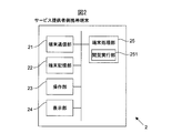
- FIG. 2 is a diagram illustrating an example of a schematic configuration of the service provider mobile terminal 2.
- the service provider mobile terminal 2 connects to the server 3 via the base station 4, the mobile communication network 5, the gateway 6, and the Internet 7, and communicates with the server 3.
- the service provider-side mobile terminal 2 displays form information that displays the previous (or past date) text history information corresponding to the service user in response to the operation of the operation unit 23 (button or the like) by the service provider. Etc. to the server 3.
- the service provider mobile terminal 2 receives and outputs the form information displaying the previous (or past date) text history information corresponding to the service user from the server 3.
- the service provider-side portable terminal 2 includes a terminal communication unit 21, a terminal storage unit 22, an operation unit 23, a display unit 24, and a terminal processing unit 25.
- a tablet terminal is assumed as the service provider-side mobile terminal 2, but the present invention is not limited to this.
- the service provider-side mobile terminal 2 may be applied to the present invention, for example, a tablet PC, a notebook PC, a multi-function mobile phone (so-called “smart phone”), a mobile phone (so-called “feature phone”), and mobile information.
- a terminal Personal Digital Assistant, PDA
- a wearable terminal or the like may be used.
- the terminal communication unit 21 includes a communication interface circuit including an antenna whose sensitivity band is a predetermined frequency band, and connects the service provider side mobile terminal 2 to the wireless communication network.
- the terminal communication unit 21 establishes a radio signal line using a CDMA (Code Division Multiple Access) method, an LTE (Long Term Evolution) method, or the like with the base station 4 through a channel assigned by the base station 4. Communication with the station 4 is performed. Then, the terminal communication unit 21 transmits the data supplied from the terminal processing unit 25 to the server 3 or the like. Further, the terminal communication unit 21 supplies data received from the server 3 or the like to the terminal processing unit 25.
- CDMA Code Division Multiple Access
- LTE Long Term Evolution
- the terminal storage unit 22 includes, for example, at least one of a semiconductor memory device, a magnetic disk device, and an optical disk device.
- the terminal storage unit 22 stores an operating system program, a driver program, an application program, data, and the like used for processing in the terminal processing unit 25.
- the terminal storage unit 22 stores an input device driver program for controlling the operation unit 23, an output device driver program for controlling the display unit 24, and the like as driver programs.
- the terminal storage unit 22 stores, as an application program, a browsing program that acquires and outputs form information that displays previous (or past date) text history information.
- the terminal storage unit 22 stores, as data, form information that displays the previous (or past date) text history information.
- the terminal storage unit 22 may temporarily store temporary data related to a predetermined process.
- the operation unit 23 may be any device as long as the operation of the service provider side mobile terminal 2 is possible, for example, a touch panel, a touch pad, a keyboard, or the like.
- the service provider can input characters, numbers, and the like using the operation unit 23.
- the service provider can also perform handwriting input using the operation unit 23.
- the service provider may use the operation unit 23 to input the image data or moving image data captured by the camera or the audio data recorded by the microphone.
- the operation unit 23 When operated by the service provider, the operation unit 23 generates a signal corresponding to the operation. The generated signal is supplied to the terminal processing unit 25 as an instruction from the service provider.
- the display unit 24 may be any device as long as it can output data such as video, images, characters, and the like, for example, a liquid crystal display, an organic EL (Electro-Luminescence) display, or the like.
- the display unit 24 outputs in accordance with the data supplied from the terminal processing unit 25.
- the terminal processing unit 25 includes one or a plurality of processors and their peripheral circuits.
- the terminal processing unit 25 controls the overall operation of the service provider side mobile terminal 2 and is, for example, a CPU (Central Processing Unit).
- the terminal processing unit 25 includes a terminal communication unit so that various processes of the service provider-side mobile terminal 2 are executed in an appropriate procedure according to a program stored in the terminal storage unit 22, an operation of the operation unit 23, and the like. 21 controls the operation of the display unit 24 and the like.
- the terminal processing unit 25 executes processing based on programs (operating system program, driver program, application program, etc.) stored in the terminal storage unit 22. Further, the terminal processing unit 25 can execute a plurality of programs (such as application programs) in parallel.
- the terminal processing unit 25 includes at least a browsing execution unit 251.
- Each of these units is a functional module realized by a program executed by a processor provided in the terminal processing unit 25. Or these each part may be mounted in the service provider side portable terminal 2 as firmware.
- the browsing execution unit 251 acquires and displays display data related to creation of a service provision plan. That is, in response to an instruction from the service provider, a request for form information displaying the previous (or past date) text history information corresponding to the service user is sent to the server 3 via the terminal communication unit 21. Send. Further, the browsing execution unit 251 receives corresponding form information from the server 3 via the terminal communication unit 21. The browsing execution unit 251 creates drawing data based on the received form information. That is, the browsing execution unit 251 analyzes the received form information to identify control data and content data, lays out the specified content data in accordance with the identified control data, and creates drawing data. Then, the browsing execution unit 251 outputs the created drawing data to the display unit 24. In addition, the created drawing data is output and displayed on the display unit 24 by the browsing execution unit 251, and characters and the like are input by the operation unit 23 to the inputable area of information displayed on the display unit 24. Is called.
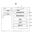
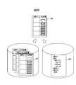
- FIG. 3 is a diagram illustrating an example of a schematic configuration of the server 3.
- the server 3 outputs form information in response to a request from the service provider mobile terminal 2. Further, the server 3 transmits the output form information to the service provider mobile terminal 2.
- the server 3 includes a server communication unit 31, a server storage unit 32, and a server processing unit 33.
- the server communication unit 31 includes a communication interface circuit for connecting the server 3 to the Internet 7 and communicates with the Internet 7. And the server communication part 31 supplies the data received from the service provider side portable terminal 2 grade
- the server storage unit 32 includes at least one of a magnetic tape device, a magnetic disk device, a flash memory, an optical disk device, and other memories, for example.
- the server storage unit 32 stores an operating system program, a driver program, an application program, data, and the like used for processing in the server processing unit 33.
- the server storage unit 32 stores, as an application program, an information management support program or the like that outputs the form information displaying the previous (or past date) text history information corresponding to the service user.
- the server storage unit 32 manages, as data, a service provision plan management table (FIG. 4A) for managing a service provision plan, an implementation procedure management table (FIG. 4B) for managing an implementation procedure of service actions, and text history information.
- a text history information management table (FIG. 4C), a form layer information management table (FIG. 5A) for managing form layer information, a form history information management table (FIG. 5B) for managing form history information, and the like are stored. Further, the server storage unit 32 may temporarily store temporary data related to a predetermined process.
- the server processing unit 33 includes one or a plurality of processors and their peripheral circuits.
- the server processing unit 33 comprehensively controls the overall operation of the server 3 and is, for example, a CPU.
- the server processing unit 33 is configured so that various processes of the server 3 are executed in an appropriate procedure according to a program stored in the server storage unit 32, a request from the service provider side portable terminal 2, and the like. The operation of 31 etc. is controlled.
- the server processing unit 33 executes processing based on programs (operating system program, driver program, application program, etc.) stored in the server storage unit 32. Further, the server processing unit 33 can execute a plurality of programs (such as application programs) in parallel.
- the server processing unit 33 includes a form image information acquisition unit 331, a form arrangement information acquisition unit 332, a registration unit 333, an extraction unit 334, and a form output unit 335.
- Each of these units is a functional module realized by a program executed by a processor included in the server processing unit 33. Alternatively, each of these units may be mounted on the server 3 as firmware.
- the form image information acquisition unit 331 executes step S100 (see FIG. 7) of the form layer information arrangement operation flow by the server.
- the form layout information acquisition unit 332 executes step S101 (see FIG. 7) of the form layer information layout operation flow by the server.
- the registration unit 333 executes step S102 (see FIG. 7) of the layout operation flow of the form layer information by the server and step S207 (see FIG. 10) of the operation sequence by the information management support system 1.
- the extraction unit 334 executes steps S202 and S203 (see FIG. 10) of the operation sequence by the information management support system 1.
- the form output unit 335 executes steps S201, S204, and S205 (see FIG. 10) of the operation sequence by the information management support system 1.
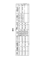
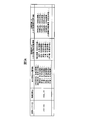
- 4 and 5 are diagrams showing examples of data structures of various management tables.
- FIG. 4A shows a service provision plan management table for managing service provision plans.
- the service provision plan management table stores not only future plans created in advance by the service provider, but also the results of execution of the plans.
- the service provision plan management table includes, for each individual service provision plan, the ID of the individual service provision plan, the ID of the service user related to the individual service provision plan, the ID of the service provider, the service provision date and time, and the ID of the provided service action
- the form layer ID, the service provision status (“not yet” or “done”), the text history ID, the form history ID, and the like are stored. For convenience, only “USER_001” is displayed as the service user ID, but information related to other service users can be managed in the same manner in this service provision plan management table.
- the service provision status is changed from “not yet” to “done” when the form history information and the text history information are stored after the planned visit service is implemented.
- these pieces of information mainly relate to the schedules of service users and service providers, but the present invention is not limited to this.
- information related to various plans such as the flow of the entire business may be included.
- a plan created in advance by the service provider is registered in the service provision plan management table. Then, after providing the service based on the plan created by the service provider, the service provision plan management table further accumulates history information of results (form history information, text history information, etc.) performed on the plan. Is done.
- FIG. 4B shows an execution procedure management table for managing the execution procedure of the service action.
- the execution procedure management table stores, for each service action, the ID and name of the service action, the execution procedure, and the like.
- the action to be observed is “1. exudate from the sacral region, bleeding”, “2. fever”, etc. Set in the procedure management table.
- the provided service action ID “ACTION_001” is associated with the provided service action ID stored in the action ID column of the service provision plan management table of FIG. 4A described above.
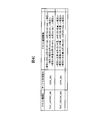
- FIG. 4C shows a text history information management table for managing text history information.
- the text history information management table stores, for each text history, the ID of the text history, the ID of the service user, text history information, and the like.
- the items of the text history information and the values thereof are expressed by structured text such as XML for each implementation date and / or implementation time, so that the text history information items can be easily extracted.
- the text history information may be in any format, such as CSV format, JSON format, table format, etc., as long as the items and their values are expressed for each implementation date and / or implementation time.
- the text history information in the text history management table of FIG. 4C stores text history information for each service user, but may be stored together for each service user and service action.
- the ID of the text history (for example, “TEXT_HISTRY — 001” is associated with the ID of the text history stored in the text history ID column of the service provision plan management table of FIG. 4A described above.
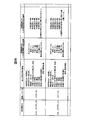
- FIG. 5A shows a form layer information management table for managing form layer information.
- the form layer information management table includes, for each form layer information, an ID of the form layer information, an ID of the form image information, an arrangement information of the display area, an arrangement information of an inputable area with an initial value, an inputable area without an initial value The arrangement information etc. are stored.
- the display area is an area for displaying information that cannot be modified, or an area for selecting the displayed information.
- the inputable area is an area where information that can be corrected can be displayed.
- the display area placement information, the placement information of the inputable area with initial value, and the placement information of the inputable area without the initial value are a layer that is a pair of the item name of each area and each vertex coordinate of each area. Indicates information. Further, each vertex coordinate of each area may be stored as a set together with the item name of the area in the form history information, and only the item name of the area may be held as the form layer information.
- the first inputable area is an inputable area with an initial value in which an arbitrary item name is defined.
- the text history information is displayed as the initial value when the form information is output according to the defined item name.
- the second inputable area is an inputable area having no initial value and no initial value when the form information is output.
- a radio button without an initial value may be provided in an inputable area without an initial value.
- the item name may be “presence / absence record”, and a radio button without an initial value such as “ ⁇ No ⁇ Yes” may be displayed in an inputable area without an initial value.
- a radio button without an initial value such as “Yes” or “No” may be displayed in an inputable area without an initial value, with the item name “not recorded”.
- the display of the inputable area without the initial value may be a check box or the like instead of the radio button, and may be any content item.
- the form layer ID (for example, “LAYER — 001”) is associated with the form layer ID stored in the form layer ID column of the service provision plan management table of FIG. 4A described above.
- FIG. 5B shows a form history information management table for managing form history information.
- the form history information management table includes, for each form history, the ID of the form history, the ID of the form layer, display information of the display area, display information of an inputable area with an initial value, display information of an inputable area without an initial value Memorize etc.
- the form history information management table is a table that is referred to when all past form information including form image information as well as past history information is requested.
- the display information of the display area, the display information of the input possible area with the initial value, and the display information of the input possible area without the initial value are the item name of each area and the text information input and displayed in each area. Indicates a pair.
- the report history ID (for example, “SHEET_HISTRY_130” is associated with the report history ID stored in the report history ID column of the service provision plan management table of FIG. 4A described above.
- the information registered in each table is associated with each other by ID.
- the extraction unit 334 of the server 3 searches the information registered in each table with the service user ID, thereby associating with each other.
- the extracted information can be extracted.
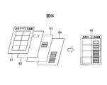
- FIG. 6 is a diagram showing an example of a schematic configuration when displaying the extracted form layer information and history information.
- the form image information 61 obtained by scanning the form of the paper service record on the paper medium, the layer information 62 of the display area, the layer information 63 of the input available area with the initial value, and the input without the initial value
- the layer information 64 of the possible area is shown.
- the form image information 61 is not necessarily a form scanned from a paper medium.
- a form file electronically created by word processing software, spreadsheet software, or the like may be used as data of the form image information 61 as it is.
- the form image information 61 obtained by scanning the form of the paper medium visit service record, the layer information 62 of the display area, and the initial value with text history information displayed as an initial value.
- the layer information 63 of the area and the layer information 64 of the inputable area without an initial value are arranged based on the arrangement information, and the form layer information 65 output in an overlapping manner is shown.
- the appearance on the right side of the arrow in FIG. 6A is one form, it has a layered format as shown on the left side of the arrow in FIG. 6A, and the way data is handled differs depending on the layer. Details will be described later.
- form information 66 in which text information “90 to 140” is input via the operation unit 23 of the service provider mobile terminal 2 of the service provider in the input enabled area is shown. .
- the extraction unit 334 can extract the text information input last time or in the past corresponding to the service user from the text history information 68 instead of the form history information 67. For example, when searching for past information, the extraction unit 334 can exclude the form image information 61 from the extraction target range and narrow down the extraction target range. Input text information can be extracted quickly.
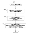
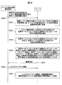
- FIG. 7 is a diagram showing an example of an operation flow for arranging the form layer information by the server. The flow in FIG. 7 will be described with reference to FIGS.
- the operation flow described below is executed mainly by the server processing unit 33 in cooperation with each element of the server 3 based on a program stored in the server storage unit 32 in advance.
- the form image information acquisition unit 331 acquires form image information 61 obtained by scanning a form created for the visit service (step S100).
- the form may be scanned by a scanner (not shown) in the server 3 of FIG. 3, or the scanned form image information 61 may be received via the server communication unit 31.
- the scanned form image information 61 may be PDF, JPG, GIF, or PNG as long as it is image information of a form.
- word processing software or spreadsheet software may be used. It may be form data created electronically from the beginning.
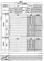
- FIG. 8 is a diagram showing an example of the form image information 61 obtained by scanning a paper service visit service record.
- the scanned form image information 61 corresponds to the base paper, so to speak, as shown in FIG.
- the form image information 61 is used by scanning a form of paper media that has been conventionally used. Therefore, since the service provider uses the familiar layout of the form as it is, it is possible to improve information input and browsing efficiency.
- the form layout information acquisition unit 332 acquires the layout information of the input-enabled area and / or the display area defined by the form creator for the acquired form image information 61 (step S101).
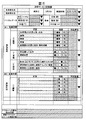
- FIG. 9 is a diagram showing an example in which the input information area and / or display area arrangement information defined by the form creator is applied to the scanned form image information 61 of FIG.
- the arrangement information is defined by the coordinate information of each area. That is, the vertex coordinate information of the rectangular area designated by the form creator using the mouse or the like is acquired from the scanned form image information 61, and the acquired vertex coordinate information of the rectangular area is defined as the arrangement information of each area. Is done.
- a user name, a provider name, an implementation date, and a plan column indicate display area arrangement information defined by the service provider.
- Blood pressure (mmHg), pulse rate (times / minute), body temperature (° C), staple food (%), side meal (%), water content (ml), and time column (dark shaded area) are the form creator Indicates the input possible area with initial value defined by.
- the fields of records, special remarks, report / instruction contents to doctors, and contact contents to family / care manager (hatched area) indicate areas where there is no initial value defined by the form creator.
- “ ⁇ None ⁇ Yes” in the record column (shaded area) is defined as “presence / absence record”. “Yes” or “No” in the record column (shaded area) is defined as “not done”.
- the registration unit 333 stores the acquired form image information 61 and the defined input-enabled area and / or display area arrangement information in the form layer information stored in the storage unit of the form created for the visit service ( Step S102).
- the registration unit 333 uses the form layer information management shown in FIG. 5A in the storage unit as the input information and / or display area arrangement information shown in FIG. 9 and the scanned form image information 61 defined by the form creator.
- the form layer information management shown in FIG. 5A in the storage unit as the input information and / or display area arrangement information shown in FIG. 9 and the scanned form image information 61 defined by the form creator.
- the form creator uses the form layer information management shown in FIG. 5A in the storage unit as the input information and / or display area arrangement information shown in FIG. 9 and the scanned form image information 61 defined by the form creator.
- the form layer information management shown in FIG. 5A in the storage unit as the input information and / or display area arrangement information shown in FIG. 9 and the scanned form image information 61 defined by the form creator.
- each vertex coordinate ab (Do not record 1, each vertex coordinate v), (Do not record 2, each vertex coordinate w), ((T) Implementation notes, each vertex coordinate x), (Do not record 3, each vertex coordinate y) (Not done record 4, each vertex coordinate z), (not done record 5, each vertex coordinate aa), ((E) special instructions for guidance, each vertex coordinate ab).
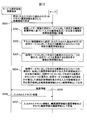
- FIG. 10 shows an example of an operation sequence by the information management support system 1. The operation sequence of FIG. 10 will be described with reference to FIGS.
- the operation sequence described below is mainly performed by the terminal processing unit 25 and the server processing unit 33 based on the programs stored in the terminal storage unit 22 and the server storage unit 32 in advance. And executed in cooperation with each element of the server 3.
- the following three will be described as an example of pre-processing of the operation sequence of FIG.
- the administrator of the organization that provides the service has the service user ID, service provider ID, service provision date and time, provided service action ID, and form layer ID in the service provision plan management table, and This is to set the service action ID, name, and implementation procedure in the implementation procedure management table.
- the service provider's mobile terminal 2 of the service provider logs in to the server 3 while providing the home-visit nursing service on August 5, and the service provider's ID entered by the service provider via the operation unit 23 Is transmitted to the server 3.
- the service provider side mobile terminal 2 requests the form information 66 displaying the text history information 68 of the previous time (or the past date input) corresponding to the service user together with the service user ID. Then, the data is transmitted to the server 3 via the terminal communication unit 21 (step S200).
- the request for the form information 66 may be any information as long as the information can identify the plan information 66 for which plan in the service provision plan management table.
- the past date may include a year.
- the past date may be a past time instead of a past date.
- the form output unit 335 receives a request for the form information 66 from the service provider mobile terminal 2 via the server communication unit 31.
- the form output unit 335 refers to the service provision plan management table and the form layer information management table based on the received request for the form information 66 and identifies the form layer ID associated with the service user ID.
- the form output unit 335 arranges an inputable area and / or a display area in the form image information 61 based on the form arrangement information corresponding to the specified form layer ID (step S201).
- the form output unit 335 refers to the service provision plan management table and the form layer information management table, and adds the form layer ID of the form layer information recorded in the record of the service user ID “USER_001” to the arrangement information of “LAYER_001”. Based on this, an input enabled area and / or a display area are arranged in the form image information 61, as shown in FIG.
- the form output unit 335 arranges a radio button of “Yes / No / Yes”.
- the form output unit 335 arranges a radio button “Yes” and “No”.
- the extraction unit 334 refers to the service provision plan management table and the text history information management table, and the previous visit service (or the past date input) provided to the service user from the text history information 68.
- the history information of at least one item of the business form is extracted (step S202).
- the extraction unit 334 refers to the service provision plan management table and the execution procedure management table, and based on the action ID recorded in the service provision plan management table of the service user ID, the action ID of the execution procedure management table. Is identified. Thereby, the extraction unit 334 extracts implementation plan information indicating a plan for implementing the visit service, of at least one item of the form created for the visit service (step S203).
- the extraction unit 334 refers to the service provision plan management table and the execution procedure management table, and for the service user ID “USER_001”, the service action IDs are “ACTION_001”, “ACTION_002”, and “ACTION_012”.
- the service action IDs are “ACTION_001”, “ACTION_002”, and “ACTION_012”.
- the implementation procedure "1. exudate from the sacrum, bleeding 2. fever 3. foul odor 4. pain 5. redness of the skin around the wound, nostalgic tissue --, "1. wash with mild hot water 2. treatment of pressure ulcer -- , And “1. Explain to contact NS when there is a large amount of exudate and bleeding. 2. Instruct to contact when excrement is contaminated. 3. Contact the visiting nurse when abnormal.” Are extracted.
- the visit NS refers to a visit Nurse Station.
- the extraction unit 334 extracts the current service date (8/5, 8:00 to 8:30) with reference to the service provision plan management table.
- the extraction unit 334 extracts the user name and the provider name from the server storage unit 32 by a known method.
- the form output unit 335 includes an input-enabled area and / or display area for displaying the extracted history information of at least one item of the form created for the visit service, and a form created for the visit service. At least one item, an input-enabled area and / or a display area for displaying the extracted execution plan information indicating a plan for implementing the visit service, is output as the form information 66 together with the form image information 61 (step S204).
- the form output unit 335 refers to the arrangement information reference of the display area of the form layer information management table, and the extraction unit 334 extracts “1. Exudate from sacrum, bleeding 2. Fever 3. Odor 4. Pain 5. Redness of skin around the wound / paper tissue ”,“ 1. Washing with warm water 2. Treatment of pressure ulcers... ”, and“ 1. Exudate, explaining to contact NS when there is a lot of bleeding 2. Excrement Instructor to contact when contaminated 3. Contact the visiting nurse when abnormal ... "is displayed in each item of the display area arranged by the form output unit 335 in step S201.
- the form output unit 335 refers to the inputable area and display area arrangement information of the form layer information management table, and extracts information other than the information extracted by the extraction unit 334 in steps S202 and S203 (service date and time “8/5, 8:00 to 8:30 ", the user name and the provider name) are also displayed in the respective items of the input possible area and the display area arranged by the form output unit 335 in step S201.
- the form output unit 335 outputs the input enabled area and / or display area for displaying each item as the form information 66 together with the form image information 61.
- the form output unit 335 transmits the output form information 66 to the service provider mobile terminal 2 via the server communication unit 31 (step S205).
- the browsing execution unit 251 outputs the form information 66 received from the server 3 to the display unit 24 via the terminal communication unit 21.
- the service provider browses the form information 66 output to the display unit 24 and inputs text information or the like into the input enabled area via the operation unit 23.
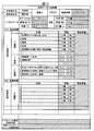
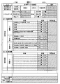
- FIG. 11 shows the text history information 68 of the previous August 1 and the information indicating the plan to be implemented on August 5 when the service is performed on August 5 of the service provider mobile terminal 2. It is a figure which shows an example of the form information 66 output to the display part 24.
- FIG. 11 shows the text history information 68 of the previous August 1 and the information indicating the plan to be implemented on August 5 when the service is performed on August 5 of the service provider mobile terminal 2. It is a figure which shows an example of the form information 66 output to the display part 24.
- # 1 short-term target plan columns indicate display areas for displaying information that cannot be modified. Therefore, the service provider cannot input or correct information in the display area that displays information that cannot be corrected.
- # 2 short-term goal is planned, display of information that cannot be modified is also displayed in the # 2 short-term goal plan column (lightly shaded area).
- the text history information 68 is displayed as an initial value at the time of output, and an input enabled area with an initial value is shown. Therefore, even if the current service provider is a different service provider from the previous service provider, the current service provider is a vital sign between the previous and previous service users and the current service user. It is possible to quickly recognize changes in health status. In addition, since the service provider can input a form based on or with reference to the text information input in the previous or past displayed in the input available area, it is possible to reduce the load of the form input.
- the fields of records, special notes, reports / instructions to doctors, and contact details to family / care managers indicate areas where there is no initial value. Therefore, the service provider who performs the visit service can input the execution record to the input enable area via the operation unit 23 while viewing and confirming each plan displayed as the execution plan information. In addition, since the service provider can confirm the plan and its execution record in the same form, the service load on the service provider can be reduced.
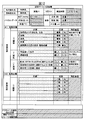
- FIG. 12 is a form in which the text history information 68 on August 1 of FIG. 11 and the execution plan information indicating the plan to be executed on August 5 are output to the display unit 24 of the mobile terminal 2 on the service provider side.
- the information about the implementation record information, vital data, and meal that the service provider performed the implementation plan information on August 5 was input to the information 66 via the operation unit 23 of the service provider mobile terminal 2. It is a figure which shows an example of the form information 66.
- a blood pressure meter, a pulse meter, or a thermometer measures vital data (blood pressure, pulse, temperature, etc.) of the service user, and the vital data of the service user measured by the blood pressure meter, pulse meter, or thermometer
- the service provider's mobile terminal receives the service user's vital data from the sphygmomanometer, pulse meter, or thermometer, and the service provider's mobile terminal receives it. Data may be entered.
- the terminal processing unit 25 transmits the text information input to the input available area by the service provider via the operation unit 23 to the server 3 via the terminal communication unit 21 (step S206).
- the registration unit 333 receives the text information input in the input possible area via the server communication unit 31.
- the registration unit 333 refers to the service provision plan management table, the form history information management table, and the text history information management table, and converts the received input text information into the history information and text history information 68 of the corresponding form history information 67, respectively.
- history information step S207.
- the text information input in the input enabled area is stored in a state of being associated with each other in two forms of the form history information 67 and the text history information 68.
- the extraction unit 334 can extract the text information input last time or in the past not from the form history information 67 but from the text history information 68, and excludes the form image information 61 from the extraction target range, and the extraction target range. Can be narrowed down. Therefore, the extraction unit 334 can quickly extract text information input in the previous time or the past.
- the extraction unit 334 extracts the items of the text history information 68 not from the visit service record but also from other forms (visit service report, visit service monitoring, etc.), and the form output unit 335 displays the extracted items.
- the text history information 68 is output together with the form image information 61 of other forms in the inputable area and / or the vicinity of the inputable area.
- the service provider can refer to the stored item and the value of the item from any form, and can reuse the item without re-inputting the value of the same item.
- the text information has an advantage that it can be used, for example, for information analysis and statistics.
- the text information to be stored is stored in the display information in the display area of the form history information management table. Thereby, the service provider can use the form history information 67 as a report as it is.
- the registration unit 333 stores “TEXT_HISTRY — 001”, “TEXT_HISTRY — 002”,... Storing the text history information 68 in the text history ID of the service provision plan management table.
- the registration unit 333 stores “SHEET_HISTRY_131” in which the form history information 67 is stored in the form history ID of the service provision plan management table. The registration unit 333 then changes the corresponding service provision status in the service provision plan management table from “not yet” to “done”.
- the information management support system 1 can reduce the service load on the service provider and improve the service provision efficiency.
- the record and special items column is defined as an input enabled area (hatched area) without an initial value as shown in FIG.
- the record and special items column may be defined as an input enabled area with an initial value (dark shaded area).
- the form output unit 335 outputs the input possible area for displaying the extracted previous (or past date) text history information 68 as the form information 66 together with the form image information 61.
- this time for example, August 5
- the form output unit 335 performs a predetermined number of times until the previous time (for example, the previous time (August 1), the previous time (July 28), 3 A pull-down area for displaying the text history information 68 (3 times before July 25) in the vicinity of the inputable area may be output as the form information 66 together with the form image information 61.
- FIG. 14 shows that text history information 68 for a predetermined number of times up to the previous time (for example, last time (August 1), last two times (July 28), three times before (July 25) three times) can be input. It is a figure which shows another example of the operation
- the operation sequence of FIG. 14 executes steps S203 and S205 to 207 in the same manner as the operation sequence of FIG. 10, but the operation sequence of FIG. 14 is different from steps S200, S201, S202, and S204 of the operation sequence of FIG. Different S200′S201 ′, 202 ′ and S204 ′ are executed.
- steps S200 ', S201', S202 ', and S204' of the operation sequence of FIG. 14 will be described with reference to FIGS.
- the service provider-side mobile terminal 2 transmits a request for the form information 66 displaying the text history information 68 for a predetermined number of times until the previous time to the server 3 via the terminal communication unit 21 (step S200 ′). .
- the form output unit 335 receives a request for the form information 66 from the service provider mobile terminal 2 via the server communication unit 31.
- the form output unit 335 refers to the service provision plan management table and the form layer information management table based on the received request for the form information 66 and identifies the form layer ID associated with the service user ID. Then, the form output unit 335 arranges the inputable area and / or the display area in the form image information 61 based on the form arrangement information corresponding to the specified form layer ID (step S201 ').
- the form output unit 335 arranges “presence / absence recording” and / or “non-recording”.
- the form output unit 335 refers to the text history information management table, acquires the last checked item and its value pair from the text history information 68 of “presence / absence record” and / or “do not record”, and checked the previous time You may arrange
- the form output unit 335 may arrange “presence / absence recording” and / or “not recording” not as a checked state but as an inputable area without an initial value.
- the extraction unit 334 extracts the history information of at least one item of the form created for the visit service for a predetermined number of times from the text history information 68 to the previous time (step S202 ').
- the form output unit 335 includes at least one item of the form created for the visit service, a pull-down area for displaying the extracted history information in the vicinity of the inputable area, and at least one of the forms created for the visit service.
- the input possible area and / or display area for displaying the extracted execution plan information indicating the plan for executing the visit service of the item is output as the form information 66 together with the form image information 61 (step S204 ′).
- FIG. 15 shows that text history information 68 for a predetermined number of times up to the previous time (for example, last time (August 1), last two times (July 28), three times before (July 25) three times) can be input.
- An example of the form information 66 in which a pull-down area displayed in the vicinity of the area is output together with the form image information 61 is shown.
- the pull-down area (dark shaded area displaying ⁇ and ⁇ ) displays the text history information 68 in a pull-down area near the input-capable area so that it can be selected, and is selected by the service provider via the operation unit 23.
- This is an area for inputting the text history information 68 to the inputable area. That is, the pull-down area has both the input area and the display area in which the text history information 68 can be selected and displayed in the pull-down area near the input area.
- the service provider can also correct the selected text history information 68 in the input enabled area after selecting the text history information 68 of the pull-down area near the input enabled area.
- the pull-down area other than the execution time column is a predetermined number of times up to the previous time (for example, last time (August 1), last time (July 28), three times before (July 25)) Since it is difficult to determine which text history information 68 should be displayed as the initial value, the initial value is not displayed. Note that the previous (August 1) text history information 68 may be displayed as an initial value in all pull-down areas other than the execution time column.
- the service provider can select an input possible area (body temperature (° C.) field), and can select text history information 68 in a pull-down area near the input possible area (body temperature (° C.) field).
- body temperature (° C.) field A displayed example is shown.
- the service provider selects “36.7 (July 28th)” in the pull-down area near the input possible area in the body temperature (° C.) column of FIG. 16, the body temperature (° C.) column can be input. In the area, “36.7” is input.
- the service provider confirms or corrects “36.7” input in the input enabled area and inputs the form.
- the service provider can select the text history information 68 to be used this time from the text history information 68 of the same item for a predetermined number of times until the previous time, via the operation unit 23, an option for input can be selected. Can be increased. Further, the data amount of the text history information 68 for the predetermined number of times until the previous time in the inputable area is overwhelmingly smaller than the data amount of the entire form information 66 including the form images for the predetermined number of times until the previous time. Therefore, the extraction unit 334 can quickly extract the text history information 68 for a predetermined number of times until the previous time in the input-enabled area, and the service provider mobile terminal 2 can quickly output the form information 66 to the display unit 24. it can.
- the service provider also stores any text history information 68 of the predetermined number of times until the previous time in the pull-down area in the vicinity of the input-capable area in the input-capable area other than the body temperature (° C.) column of FIG. While selecting via the operation unit 23, the form input is recommended.
- the registration unit 333 stores “presence / absence record” and / or “do not record” and item value pairs in the text history information 68 of the text history information management table together with the date.
- the form output unit 335 may output the form information 66 to which a function for checking the input information is added.
- the function of checking the input information is realized by adding a software program to the form information 66.
- FIG. 17 is a diagram illustrating an example of the form information 66 to which a function for checking input information is added.
- the column of the visit service record in the form information 66 output to the display unit 24 of the service provider side portable terminal 2 in FIG. 17 is the same as that in FIG. 11, but the input button 1700 and the upper right in the upper left part of the form information 66.
- Two buttons of a save button 1701 are further added to the section.
- the input button 1700 and the save button 1701 are buttons that do not exist in the paper medium form, and are displayed as buttons that do not belong to any layer in FIG. 6A.
- step S205 of FIG. 10 described above when the execution plan information including the history information is displayed on the display unit 24, the input button 1700 is pressed (clicked) by the service provider via the operation unit 23. Then, the previous history information that has been displayed disappears from the input enabled area, and the input enabled area is in a state of waiting for input.
- the form information 66 is displayed.
- the added check function checks items in the input-enabled area. Then, the check function added to the form information 66 extracts the items that are not input although the input is essential, and displays the column of the item in a conspicuous color such as red, The message “Not entered” is displayed.
- the check function added to the form information 66 may perform a check other than the check of the input-required items described above.
- the check function added to the form information 66 extracts items for which numeric input is mandatory but numeric input is not performed, and displays the column of the item in a conspicuous color such as red. Or a message such as “Mandatory number input required” may be displayed.
- the check function added to the form information 66 extracts items for which date input or time input is not performed even though date input or time input is essential, and the column of the item is displayed. It may be displayed in a conspicuous color such as red, or a message may be displayed as “date input required” or “time input required”.
- the check function added to the form information 66 may check the input vital data by comparing the input vital data with the vital data of the previous text history information 68.
- the check function added to the form information 66 is an input in which the input vital data changes by a predetermined value or a predetermined ratio or more when the input vital data changes by a predetermined value or a predetermined ratio or more from the vital data of the previous text history information 68.
- the color of the vital data inputable area is changed, or a warning message is displayed on the display unit 24.
- the service provider can quickly recognize a change in the vital data between the service user of the previous or previous date and the current service user by a predetermined value or a predetermined ratio or more.
- a check function for the input operation to the displayed information is further added, so that the service provider can refer to the past history or based on the referred history. It is now possible to perform a series of processing such as recording related actions in a sense close to that of working with conventional paper media.
- the information management support system 1 reduces the service load of the service provider. It becomes possible to improve the service provision efficiency.
- a computer program for causing a computer to realize the functions of the terminal processing unit 25 and the server processing unit 33 is recorded on a computer-readable recording medium such as a semiconductor recording medium, a magnetic recording medium, or an optical recording medium. May be provided in the form and installed in the server storage unit 32 from the recording medium using a known setup program or the like.
Landscapes
- Engineering & Computer Science (AREA)
- Business, Economics & Management (AREA)
- Health & Medical Sciences (AREA)
- Strategic Management (AREA)
- Human Resources & Organizations (AREA)
- General Health & Medical Sciences (AREA)
- Theoretical Computer Science (AREA)
- Entrepreneurship & Innovation (AREA)
- Primary Health Care (AREA)
- Tourism & Hospitality (AREA)
- General Physics & Mathematics (AREA)
- Physics & Mathematics (AREA)
- Medical Informatics (AREA)
- Public Health (AREA)
- Epidemiology (AREA)
- Marketing (AREA)
- Economics (AREA)
- General Business, Economics & Management (AREA)
- Quality & Reliability (AREA)
- Data Mining & Analysis (AREA)
- Operations Research (AREA)
- Child & Adolescent Psychology (AREA)
- Artificial Intelligence (AREA)
- Audiology, Speech & Language Pathology (AREA)
- Computational Linguistics (AREA)
- General Engineering & Computer Science (AREA)
- Medical Treatment And Welfare Office Work (AREA)
- Management, Administration, Business Operations System, And Electronic Commerce (AREA)
- User Interface Of Digital Computer (AREA)
Priority Applications (4)
| Application Number | Priority Date | Filing Date | Title |
|---|---|---|---|
| KR1020167030380A KR20160138564A (ko) | 2014-05-01 | 2015-04-27 | 정보 관리 지원 시스템에 있어서의 서버, 그 제어 방법, 및 그 제어 프로그램 |
| US15/308,041 US20170053070A1 (en) | 2014-05-01 | 2015-04-27 | Server for information management support system, control method therefor, and control program therefor |
| EP15785267.4A EP3139338A4 (en) | 2014-05-01 | 2015-04-27 | Server for information management support system, control method therefor, and control program therefor |
| CN201580021475.1A CN106462925A (zh) | 2014-05-01 | 2015-04-27 | 信息管理支援系统中的服务器、其控制方法及其控制程序 |
Applications Claiming Priority (2)
| Application Number | Priority Date | Filing Date | Title |
|---|---|---|---|
| JP2014094671 | 2014-05-01 | ||
| JP2014-094671 | 2014-05-01 |
Publications (1)
| Publication Number | Publication Date |
|---|---|
| WO2015166925A1 true WO2015166925A1 (ja) | 2015-11-05 |
Family
ID=54358652
Family Applications (1)
| Application Number | Title | Priority Date | Filing Date |
|---|---|---|---|
| PCT/JP2015/062730 WO2015166925A1 (ja) | 2014-05-01 | 2015-04-27 | 情報管理支援システムにおけるサーバ、その制御方法、及びその制御プログラム |
Country Status (6)
Families Citing this family (4)
| Publication number | Priority date | Publication date | Assignee | Title |
|---|---|---|---|---|
| JP6926484B2 (ja) * | 2017-01-17 | 2021-08-25 | 富士フイルムビジネスイノベーション株式会社 | 電子文書業務システム及びプログラム |
| JP6565106B1 (ja) * | 2018-07-10 | 2019-08-28 | 株式会社ミトリ | ワークフローシステム及びそのプログラム |
| CN112107425B (zh) * | 2019-06-21 | 2023-04-28 | 尤妮佳股份有限公司 | 输出装置、输出方法以及存储介质 |
| JP2023048265A (ja) * | 2021-09-28 | 2023-04-07 | 村田機械株式会社 | 電子帳票システム |
Citations (5)
| Publication number | Priority date | Publication date | Assignee | Title |
|---|---|---|---|---|
| JP2001344350A (ja) * | 2000-06-01 | 2001-12-14 | Kiyohiro Yamamori | 介護支援システム |
| JP2002230172A (ja) * | 2001-02-06 | 2002-08-16 | Toppan Printing Co Ltd | 訪問介護方法及びサーバ |
| JP2002324210A (ja) * | 2001-04-24 | 2002-11-08 | Toshiba Corp | 文字認識処理システムおよびプログラム |
| JP2006048555A (ja) * | 2004-08-09 | 2006-02-16 | Hitachi Ltd | 介護サービス事務支援システムおよびその方法 |
| JP2008171213A (ja) * | 2007-01-12 | 2008-07-24 | Dainippon Printing Co Ltd | 電子帳票プログラムおよび電子帳票 |
Family Cites Families (5)
| Publication number | Priority date | Publication date | Assignee | Title |
|---|---|---|---|---|
| JP2002215800A (ja) | 2000-11-29 | 2002-08-02 | Toshiba Corp | 統合型在宅介護サービス支援システム、統合型在宅介護サービス支援方法、および記憶媒体 |
| US8019622B2 (en) * | 2005-10-24 | 2011-09-13 | CellTrak Technologies, Inc. | Home health point-of-care and administration system |
| US8588528B2 (en) * | 2009-06-23 | 2013-11-19 | K-Nfb Reading Technology, Inc. | Systems and methods for displaying scanned images with overlaid text |
| JP5391309B2 (ja) * | 2012-05-23 | 2014-01-15 | みずほ情報総研株式会社 | 情報管理システム、情報管理方法及び情報管理プログラム |
| CN103440264B (zh) * | 2013-08-01 | 2017-03-08 | 广东电网公司 | 电力现场作业表单的实现方法及系统 |
-
2015
- 2015-04-27 JP JP2015090324A patent/JP6377010B2/ja not_active Expired - Fee Related
- 2015-04-27 US US15/308,041 patent/US20170053070A1/en not_active Abandoned
- 2015-04-27 KR KR1020167030380A patent/KR20160138564A/ko not_active Ceased
- 2015-04-27 EP EP15785267.4A patent/EP3139338A4/en not_active Withdrawn
- 2015-04-27 WO PCT/JP2015/062730 patent/WO2015166925A1/ja active Application Filing
- 2015-04-27 CN CN201580021475.1A patent/CN106462925A/zh active Pending
Patent Citations (5)
| Publication number | Priority date | Publication date | Assignee | Title |
|---|---|---|---|---|
| JP2001344350A (ja) * | 2000-06-01 | 2001-12-14 | Kiyohiro Yamamori | 介護支援システム |
| JP2002230172A (ja) * | 2001-02-06 | 2002-08-16 | Toppan Printing Co Ltd | 訪問介護方法及びサーバ |
| JP2002324210A (ja) * | 2001-04-24 | 2002-11-08 | Toshiba Corp | 文字認識処理システムおよびプログラム |
| JP2006048555A (ja) * | 2004-08-09 | 2006-02-16 | Hitachi Ltd | 介護サービス事務支援システムおよびその方法 |
| JP2008171213A (ja) * | 2007-01-12 | 2008-07-24 | Dainippon Printing Co Ltd | 電子帳票プログラムおよび電子帳票 |
Non-Patent Citations (1)
| Title |
|---|
| See also references of EP3139338A4 * |
Also Published As
| Publication number | Publication date |
|---|---|
| EP3139338A1 (en) | 2017-03-08 |
| JP6377010B2 (ja) | 2018-08-22 |
| CN106462925A (zh) | 2017-02-22 |
| KR20160138564A (ko) | 2016-12-05 |
| JP2015222564A (ja) | 2015-12-10 |
| US20170053070A1 (en) | 2017-02-23 |
| EP3139338A4 (en) | 2017-12-20 |
Similar Documents
| Publication | Publication Date | Title |
|---|---|---|
| US11238983B2 (en) | Systems and methods for and displaying patient data | |
| Chakraborty et al. | Mobile metadata assisted community database of chronic wound images | |
| Adams et al. | Mental health problems in people living with HIV: changes in the last two decades: the London experience 1990–2014 | |
| CN103443796B (zh) | 查看病人数据的系统和方法 | |
| US20150100349A1 (en) | Untethered Community-Centric Patient Health Portal | |
| JP6377010B2 (ja) | 情報管理支援システムにおけるサーバ、その制御方法、及びその制御プログラム | |
| Van Winkle et al. | Why aren’t our digital solutions working for everyone? | |
| US20170372012A1 (en) | Patient information display system and patient information display method | |
| Phongtankuel et al. | Mobile health technology and home hospice care: promise and pitfalls | |
| Seto et al. | Implementation of a heart failure telemonitoring system in home care nursing: feasibility study | |
| JP6775203B2 (ja) | 診療支援装置、診療支援方法、診療支援プログラムおよび診療支援システム | |
| Shaw et al. | Integrating patient-generated digital health data into electronic health records (EHRs) in ambulatory care settings: EHR vendor survey and interviews | |
| US20250053685A1 (en) | Systems and methods for the securing data while in transit between disparate systems and while at rest | |
| Tariq et al. | One size does not fit all: The importance of contextually sensitive mHealth strategies for frontline female health workers | |
| Esteves et al. | A Mobile Health Application to Assist Health Professionals: A Case Study in a Portuguese Nursing Home. | |
| JP6252038B2 (ja) | 情報処理プログラム及び情報処理装置 | |
| JP7115799B1 (ja) | 情報提供方法、情報提供装置、情報提供プログラム及び記録媒体 | |
| Oakley et al. | Implementing an electronic patient handover system | |
| US10089492B2 (en) | Patient navigation and situational awareness derived through context-sensitive information blocks delivery | |
| JP2019179443A (ja) | コンピュータプログラム、端末及び方法 | |
| JP2020009339A (ja) | データ管理装置及び疲労度推定方法 | |
| US10741273B1 (en) | User friendly medical records systems, apparatuses and methods | |
| US20170076044A1 (en) | Medical-document management appratus, electronic medical record system, medical-document management system, and non-transitory computer readable medium | |
| JP5543511B2 (ja) | 業務支援装置、携帯端末及びプログラム | |
| JP2006260305A (ja) | 電子カルテ管理装置、電子カルテシステム、電子カルテ管理方法及び電子カルテ管理プログラム |
Legal Events
| Date | Code | Title | Description |
|---|---|---|---|
| 121 | Ep: the epo has been informed by wipo that ep was designated in this application |
Ref document number: 15785267 Country of ref document: EP Kind code of ref document: A1 |
|
| ENP | Entry into the national phase |
Ref document number: 20167030380 Country of ref document: KR Kind code of ref document: A |
|
| WWE | Wipo information: entry into national phase |
Ref document number: 15308041 Country of ref document: US |
|
| NENP | Non-entry into the national phase |
Ref country code: DE |
|
| REEP | Request for entry into the european phase |
Ref document number: 2015785267 Country of ref document: EP |
|
| WWE | Wipo information: entry into national phase |
Ref document number: 2015785267 Country of ref document: EP |