WO2015166524A1 - 極端紫外光生成装置 - Google Patents
極端紫外光生成装置 Download PDFInfo
- Publication number
- WO2015166524A1 WO2015166524A1 PCT/JP2014/061815 JP2014061815W WO2015166524A1 WO 2015166524 A1 WO2015166524 A1 WO 2015166524A1 JP 2014061815 W JP2014061815 W JP 2014061815W WO 2015166524 A1 WO2015166524 A1 WO 2015166524A1
- Authority
- WO
- WIPO (PCT)
- Prior art keywords
- target
- light
- trajectory
- extreme ultraviolet
- ultraviolet light
- Prior art date
- Legal status (The legal status is an assumption and is not a legal conclusion. Google has not performed a legal analysis and makes no representation as to the accuracy of the status listed.)
- Ceased
Links
Images



Classifications
-
- H—ELECTRICITY
- H05—ELECTRIC TECHNIQUES NOT OTHERWISE PROVIDED FOR
- H05G—X-RAY TECHNIQUE
- H05G2/00—Apparatus or processes specially adapted for producing X-rays, not involving X-ray tubes, e.g. involving generation of a plasma
- H05G2/001—Production of X-ray radiation generated from plasma
- H05G2/008—Production of X-ray radiation generated from plasma involving an energy-carrying beam in the process of plasma generation
-
- G—PHYSICS
- G03—PHOTOGRAPHY; CINEMATOGRAPHY; ANALOGOUS TECHNIQUES USING WAVES OTHER THAN OPTICAL WAVES; ELECTROGRAPHY; HOLOGRAPHY
- G03F—PHOTOMECHANICAL PRODUCTION OF TEXTURED OR PATTERNED SURFACES, e.g. FOR PRINTING, FOR PROCESSING OF SEMICONDUCTOR DEVICES; MATERIALS THEREFOR; ORIGINALS THEREFOR; APPARATUS SPECIALLY ADAPTED THEREFOR
- G03F7/00—Photomechanical, e.g. photolithographic, production of textured or patterned surfaces, e.g. printing surfaces; Materials therefor, e.g. comprising photoresists; Apparatus specially adapted therefor
- G03F7/70—Microphotolithographic exposure; Apparatus therefor
- G03F7/70008—Production of exposure light, i.e. light sources
- G03F7/70033—Production of exposure light, i.e. light sources by plasma extreme ultraviolet [EUV] sources
-
- H—ELECTRICITY
- H05—ELECTRIC TECHNIQUES NOT OTHERWISE PROVIDED FOR
- H05G—X-RAY TECHNIQUE
- H05G2/00—Apparatus or processes specially adapted for producing X-rays, not involving X-ray tubes, e.g. involving generation of a plasma
- H05G2/001—Production of X-ray radiation generated from plasma
- H05G2/002—Supply of the plasma generating material
- H05G2/0023—Constructional details of the ejection system
Definitions
- the present disclosure relates to an extreme ultraviolet light generator.
- LPP Laser Produced Plasma
- DPP discharge Produced Plasma
- Three types of devices have been proposed: a device of the type and a device of SR (Synchrotron Radiation) type using orbital radiation.
- An extreme ultraviolet light generation apparatus includes: a target supply unit that supplies a target from a nozzle; and a first illumination apparatus that outputs light of a first characteristic to illuminate the target output from the nozzle.
- a second illumination device for illuminating a target output from the nozzle by outputting light of a second characteristic different from the first characteristic; and photographing a target illuminated with the light of the first characteristic
- a second imaging device for imaging the target illuminated by the light of the second characteristic.
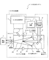
- FIG. 1 schematically shows the configuration of an exemplary LPP EUV light generation system.
- FIG. 2 shows a comparative example of an extreme ultraviolet light generation device including a target trajectory measurement device.
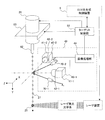
- FIG. 3 illustrates an embodiment of a control system that measures the trajectory of the target and controls the trajectory to pass through the center point of the target plasma generation region.
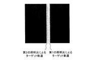
- FIG. 4 shows an image of a target irradiated with light from two directions.
- FIG. 5 shows an embodiment of a target trajectory measurement device including an illumination device that outputs illumination light of different wavelengths.
- FIG. 6 shows an embodiment of a target trajectory measurement apparatus including an illumination device that outputs illumination light at different timings.
- FIG. 7 shows operation timings of the lighting device and the imaging device.
- FIG. 8 shows an embodiment of a target trajectory measurement device including an illumination device that outputs illumination light of different polarizations.
- Embodiment 1 A target trajectory measurement device including an illumination device that outputs illumination light of different wavelengths.
- Embodiment 2 Target trajectory measurement device including an illumination device that outputs illumination light at different timings.
- Embodiment 3 A target trajectory measurement device including an illumination device that outputs light of different polarizations
- An extreme ultraviolet light generation apparatus includes: a target supply unit that supplies a target from a nozzle; and a first illumination apparatus that outputs light of a first characteristic to illuminate the target output from the nozzle.
- a second illumination device for illuminating a target output from the nozzle by outputting light of a second characteristic different from the first characteristic; and photographing a target illuminated with the light of the first characteristic
- a second imaging device for imaging the target illuminated by the light of the second characteristic.
- the measurement accuracy of the trajectory of the target may be improved because the two illumination devices emit light of different characteristics to the target and the two imaging devices capture light of different characteristics and measure the trajectory of the target.
- the "track" of the target is the actual path of the target output from the target supply device.
- FIG. 1 schematically illustrates the configuration of an exemplary LPP EUV light generation system.
- the EUV light generation device 1 may be used with at least one laser device 3.
- a system including the EUV light generation apparatus 1 and the laser apparatus 3 is referred to as an EUV light generation system 11.
- the EUV light generation system 1 may include a chamber 2 and a target supply unit 26.
- Chamber 2 may be sealable.
- the target supply unit 26 may be attached, for example, to penetrate the wall of the chamber 2.
- the material of the target supplied from the target supply unit 26 may include, but is not limited to, tin, terbium, gadolinium, lithium, xenon, or a combination of any two or more thereof.
- the wall of the chamber 2 may be provided with at least one through hole.
- a window 21 may be provided in the through hole, and the pulse laser beam 32 output from the laser device 3 may be transmitted through the window 21.
- an EUV collector mirror 23 having a spheroidal reflecting surface may be disposed inside the chamber 2.
- the EUV light collecting mirror 23 may have first and second focal points.
- a multilayer reflective film in which molybdenum and silicon are alternately stacked may be formed on the surface of the EUV light collector mirror 23.
- the EUV collector mirror 23 is preferably arranged, for example, such that its first focal point is located at the plasma generation region 25 and its second focal point is located at the intermediate focusing point (IF) 292.
- a through hole 24 may be provided in the central part of the EUV light collecting mirror 23, and the pulse laser beam 33 may pass through the through hole 24.
- the EUV light generation apparatus 1 may include an EUV light generation controller 5, a target sensor 4 and the like.
- the target sensor 4 may have an imaging function, and may be configured to detect at least one of the presence, the trajectory, the position, and the velocity of the target 27.
- the target 27 may also be referred to as a droplet 27.
- the EUV light generation apparatus 1 may include a connection part 29 that brings the inside of the chamber 2 into communication with the inside of the exposure apparatus 6. Inside the connection portion 29, a wall 291 in which an aperture is formed may be provided. The wall 291 may be arranged such that its aperture is located at a second focal position of the EUV collector mirror 23.
- the EUV light generation apparatus 1 may include a laser light traveling direction control unit 34, a laser light collecting mirror 22, a target collector 28 for collecting the target 27, and the like.
- the laser light traveling direction control unit 34 may include an optical element for defining the traveling direction of the laser light, and an actuator for adjusting the position, attitude, and the like of the optical element.
- the pulsed laser beam 31 output from the laser device 3 passes through the laser beam traveling direction control unit 34, passes through the window 21 as the pulsed laser beam 32, and enters the chamber 2 May be
- the pulsed laser beam 32 may travel along the at least one laser beam path in the chamber 2, be reflected by the laser beam focusing mirror 22, and be irradiated to the at least one target 27 as the pulsed laser beam 33.
- the target supply unit 26 may be configured to discharge the target 27 toward the plasma generation region 25 inside the chamber 2.
- the target 27 may be irradiated with at least one pulse included in the pulsed laser light 33.
- the target 27 irradiated with the pulsed laser light may be plasmatized, and radiation 251 may be emitted from the plasma.
- the EUV light 252 included in the radiation light 251 may be selectively reflected by the EUV light collecting mirror 23.
- the EUV light 252 reflected by the EUV light collecting mirror 23 may be collected at the intermediate collecting point 292 and output to the exposure apparatus 6.
- one target 27 may be irradiated with a plurality of pulses included in the pulsed laser light 33.
- the EUV light generation controller 5 may be configured to control the entire EUV light generation system 11.
- the EUV light generation controller 5 may be configured to process image data or the like of the target 27 captured by the target sensor 4. Furthermore, the EUV light generation controller 5 may be configured to control, for example, the timing at which the target 27 is supplied, the output direction of the target 27, and the like.
- the EUV light generation controller 5 is configured to perform at least one of, for example, control of the light emission timing of the laser device 3, control of the traveling direction of the pulse laser light 32, and control of the focusing position of the pulse laser light 33. It may be done.
- control of the light emission timing of the laser device 3 control of the traveling direction of the pulse laser light 32, and control of the focusing position of the pulse laser light 33. It may be done.
- the various controls described above are merely exemplary, and other controls may be added as needed.
- the present disclosure relates to an extreme ultraviolet light generation device or method including measurement of a trajectory of a target and its control device.
- the extreme ultraviolet light generation device of the present disclosure may include a target trajectory measurement device that measures the trajectory of the target with high accuracy, and may control the trajectory of the target based on the detection result of the target trajectory measurement device.
- FIG. 2 schematically shows a comparative example of the extreme ultraviolet light generation device including the target trajectory measurement device.
- the EUV light generation apparatus 1 may include a chamber 2, a laser device 3, a beam delivery system (laser light traveling direction control unit) 34, an EUV light generation control unit 5, and a target control unit 52.
- a beam delivery system laser light traveling direction control unit
- the EUV chamber 2 includes a target supply unit 26, a biaxial stage 63, a target trajectory measurement device 49, a window 21, a laser focusing optical system 22A, a plate 83, a plate 82, an EUV light focusing mirror holder 81, an EUV collector mirror 23, and a target collector 28 may be included.
- the target trajectory measurement device 49 may include at least two illumination devices 70 and at least two imaging devices 40. In FIG. 2, only one lighting device 70 and one imaging device 40 are illustrated.
- the lighting device 70 may include a light source 71, a lens 72, and a window 73.
- the light source 71 may be, for example, a lamp, an LED or a laser light source.
- the lens 72 may be, for example, a collimator.
- the imaging device 40 may include an image sensor 41, a transfer optical system 42, and a window 43.
- the image sensor 41 may be a two-dimensional CCD sensor.
- the transfer optical system 42 and the image sensor 41 may be arranged such that the reflected light from the target forms an image on the image sensor 41.
- the target supply unit 26 may be installed in the chamber 2 via a biaxial stage 63 moving in the X-axis and Z-axis directions.
- the target control unit 52 may receive the center position Pt of the target plasma generation region 25 from the exposure apparatus control unit 61 via the EUV light generation control unit 5.
- the laser focusing optical system 22A may be controlled such that the focusing point of the laser beam coincides with Pt by moving the plate 83 by the three-axis stage 85 (not shown).
- An output signal for outputting a target from the EUV light generation controller 5 to the target controller 52 may be input.
- the target control unit 52 may control the target supply unit 26 to output the target (droplet) from the nozzle 62.
- the output target is illuminated by the light of the illumination device 70, an image of the target may be imaged on the image sensor 41 by the transfer optical system 42.
- the exposure time of the image sensor 41 may be extended to a predetermined time. When the exposure time of the image sensor 41 is increased, the trajectory in which the droplet has moved can be imaged.
- the imaging device 40 may transmit the trajectory measurement signal of the target to the image processing unit 44.
- the image processing unit 44 may process the image of the target captured by the two image sensors 41.
- the image processing unit 44 may calculate the trajectory of the target from the two image processed data.
- the target trajectory measuring device 49 may measure the trajectory of the target.
- the target control unit 52 transmits a control signal to the biaxial stage 63 so that the target reaches the center position Pt of the plasma based on the trajectory of the target calculated by the image processing unit 44, and the target control unit 52
- the position may be controlled.
- the target control unit 52 calculates the amount of deviation from the target position of the trajectory of the target in the two images, and determines the amount of control of the biaxial stage 63 from the calculated amount of deviation.
- the control signal may be transmitted so that the two-axis stage 63 moves by the amount of deviation.
- pulsed laser light can be output from the laser device 3.
- the output pulsed laser light can be input to the EUV chamber 2 through the window 21 via the laser light traveling direction control unit 34.
- the pulsed laser light can reach the plasma generation region 25 and be focused and irradiated onto the droplet by the laser focusing optical system 22A. As a result, the droplets may be plasmatized to generate EUV light 252.
- FIG. 3 shows an embodiment of a control system that measures the trajectory of the target and controls the trajectory to pass through the center point of the target plasma generation region 25.
- the chamber is omitted and only the control system is illustrated.
- the target trajectory measurement device 49 includes a first imaging device 40-1, a first illumination device 70-1, a second imaging device 40-2, a second illumination device 70-2, and an image processing unit 44. May be included.
- the first lighting device 70-1 may include a light source 71-1, a lens 72-1, and a window 73-1
- the second lighting device 70-2 may include a light source 71-2 and a lens 72-2.
- a window 73-2 The first imaging device 40-1 may include an image sensor 41-1, a transfer optical system 42-1, and a window 43-1
- the second imaging device 40-2 may include an image sensor 41-2.
- the transfer optical system 42-2 and the window 43-2 may be included.
- the first lighting device 70-1 and the second lighting device 70-2 may be arranged to illuminate the targets from two directions so as to intersect each other on the trajectory of the targets.
- the irradiation direction of the light by the first lighting device 70-1 and the irradiation direction of the light by the second lighting device 70-2 are desirably orthogonal to each other, but may not necessarily be orthogonal to each other. Further, it is desirable that the irradiation direction of the light by the first lighting device 70-1 and the irradiation direction of the light by the second lighting device 70-2 be included on a plane perpendicular to the trajectory of the target, but one or both of them are The target may be irradiated from a direction deviated from the plane.
- the first imaging device 40-1 and the second imaging device 40-2 may be arranged to image targets from the Z-axis direction and the X-axis direction which are orthogonal to each other, but imaging from non-orthogonal directions You may The first imaging device 40-1 and the second imaging device 40-2 may be disposed at positions where the same target is imaged at the same timing.
- the biaxial stage 63 may be a stage that moves linearly in the X-axis and Z-axis directions.
- the biaxial stage 63 is desirably a stage that linearly moves in two orthogonal axial directions, but may move in two non-orthogonal directions if it moves in two different directions.
- the first imaging device 40-1 and the second imaging device 40-2 may be connected to the image processing unit 44.
- the image processing unit 44 and the target control unit 52 may be connected such that data output from the image processing unit 44 can be transmitted to the target control unit 52.
- the exposure time of both imaging devices 40-1 and 40-2 may be set longer than the time required for the droplet image to move on the image sensor of the imaging device.
- the image of the taken droplet may be a linear image.
- the trajectory of the target may be measured from this linear image.
- FIG. 4 shows a target image irradiated with light from two directions. As shown in FIG. 4, in the target image irradiated with light from two directions, since the image of the trajectory of the first illumination light and the image of the second illumination light are captured in duplicate, The measurement accuracy could be degraded.
- Embodiment 1 Target Trajectory Measurement Device Including Illumination Device that Outputs Illumination Light of Different Wavelengths 5.1 Configuration Embodiment of Target Trajectory Measurement Device 49 Including Illumination Device that Outputs Illumination Light of Different Wavelengths from FIG. 5 Indicates
- the first lighting device 70-1 may include a light source 71-1, a lens 72-1, and a window 73-1
- the second lighting device 70-2 may include a light source 71-2 and a lens 72-2.
- a window 73-2 The first imaging device 40-1 may include an image sensor 41-1, a transfer optical system 42-1, a window 43-1, and a filter 45-1
- the second imaging device 40-2 may include an image.
- a sensor 41-2, a transfer optical system 42-2, a window 43-2, and a filter 45-2 may be included.
- the light source 71-1 of the first lighting device 70-1 may be a light source that outputs light of a first wavelength
- the light source 71-2 of the second lighting device 70-2 may be a light source that outputs light of a second wavelength Good.
- the light source 71-1 of the first lighting device 70-1 may be a light emitting diode (LED) that outputs light of a wavelength near 450 nm
- the light source 71-2 of the second lighting device 70-2 may have a wavelength of around 660 nm. It may be a light emitting diode that outputs light.
- the filter 45-1 may be disposed on the light path between the trajectory of the target and the image sensor 41-1.
- the filter 45-1 may be a band pass filter that passes light of the first wavelength.
- the filter 45-2 may be disposed on the optical path between the trajectory of the target and the image sensor 41-2.
- the filter 45-2 may be a band pass filter that passes light of the second wavelength.
- a band pass filter that extracts light of the first or second wavelength from the image captured by the image sensor 41-1 or 42-1 may be used.
- the first imaging device 40-1 can capture an image of the trajectory of the target irradiated with the light of the first wavelength through the filter 45-1.
- light of the second wavelength may be reflected or absorbed at a high rate by the filter 45-1.
- the second imaging device 40-2 can capture an image of the trajectory of the target irradiated with the light of the second wavelength through the filter 45-2. Meanwhile, the light of the first wavelength may be reflected or absorbed at a high rate by the filter 45-2.
- two illumination devices 70-1 and 70-2 irradiate light of different wavelengths to the target, and the two imaging devices 40-1 and 40-2 receive their respective wavelengths. Since the filter corresponding to is arrange
- Embodiment 2 Target trajectory measuring device including an illumination device that outputs illumination light at mutually different timings 6.1
- FIG. 6 shows an embodiment of a target trajectory measurement device 49 including an illumination device that outputs illumination light at mutually different timings Indicates
- the first imaging device 40-1 and the second imaging device 40-2 may include a shutter.
- the shutter may be an image intensifier including a CCD electronic shutter, a mechanical shutter, a multi-channel plate.
- a control signal line for transmitting an open / close signal of the shutter may be provided between each of the image processing unit 44 and the first imaging device 40-1 and between the image processing unit 44 and the second imaging device 40-2.
- control signal lines for transmitting lighting signals may be provided between each of the image processing unit 44 and the first lighting device 70-1 and between the image processing unit 44 and the second lighting device 70-2.
- FIG. 7 shows operation timings of the illumination devices 70-1 and 70-2 and the imaging devices 40-1 and 40-2.
- the illumination devices 70-1 and 70-2 irradiate illumination light to the targets at timings that do not overlap each other, but may overlap partially as long as timings are different from each other.
- the image processing unit 44 may open the shutter of the first imaging device 40-1 at the timing when the first lighting device 70-1 is lit. At the timing when the shutter of the first imaging device 40-1 opens, the target on the trajectory can be illuminated, the target can be photographed, and the trajectory of the target can be imaged.
- the first illumination device 70-1 may be turned off and the shutter of the first imaging device 40-1 may be closed at the timing when the imaging of the target is completed.
- the image processing unit 44 may open the shutter of the second imaging device 40-2 in accordance with the timing at which the second illumination device 70-2 lights up.
- the shutter of the second imaging device 40-2 opens, the target on the trajectory can be illuminated, the target can be photographed, and the trajectory of the target can be imaged.
- the second illumination device 70-2 may be turned off and the shutter of the second imaging device 40-2 may be closed at the timing when the imaging of the target ends.
- the image processing unit 44 may transmit a control signal so that the illumination devices 70-1 and 70-2 and the imaging devices 40-1 and 40-2 operate as described above, and the above two steps are repeated.
- the trajectory of the target may be imaged.
- the illumination devices 70-1 and 70-2 irradiate illumination light to the targets at different timings, and the imaging devices 40-1 and 40-2 receive the illumination devices 70 respectively. Since the trajectory of the target is imaged in synchronization with the lighting timings of the light sources -1 and 70-2, each imaging device can image the trajectory of the target with one illumination light image. As a result, the accuracy of the trajectory measurement of the target may be improved.
- Embodiment 3 Target Trajectory Measurement Device Including Illumination Device that Outputs Illumination Light of Different Polarizations 7.1 Configuration Embodiment of Target Trajectory Measurement Device 49 Including Illumination Device that Outputs Illumination Light of Different Polarizations in FIG. 8 Indicates
- the first lighting device 70-1 may include the light source 71-1, the lens 72-1, the window 73-1, and the filter 74-1
- the second lighting device 70-2 may be the light source 71-2.
- the first imaging device 40-1 may include an image sensor 41-1, a transfer optical system 42-1, a window 43-1, and a filter 45-1
- the second imaging device 40-2 may include an image.
- a sensor 41-2, a transfer optical system 42-2, a window 43-2, and a filter 45-2 may be included.
- the light source of the first lighting device 70-1 may be a light source outputting light of the first polarization
- the light source of the second lighting device 70-2 may be a light source outputting light of the second polarization
- the polarizing filter 74-1 transmitting light of the first polarization is disposed on the light path between the light source 71-1 of the first lighting device and the trajectory of the target, and the first lighting device 70-1 The target may be irradiated with light of polarized light.
- a polarization filter 74-2 transmitting light of polarization different from the second polarization is disposed on the optical path between the light source 71-2 of the second illumination device and the trajectory of the target, and the second illumination device 70-2 is arranged. May illuminate the target with light of the second polarization. It is desirable that the first polarization and the second polarization differ by 90 ° ( ⁇ / 2), as long as they can be separated by a polarization filter.
- a filter 45-1 may be disposed on the light path between the trajectory of the target and the image sensor 41-1.
- the filter 45-1 may be a polarizing filter that transmits light of the first polarization.
- a filter 45-2 may be disposed on the optical path between the trajectory of the target and the image sensor 41-2.
- the filter 45-2 may be a polarization filter that passes light of the second polarization.
- the light of the first polarized light output from the first lighting device 70-1 and the light of the second polarized light output from the second lighting device 70-2 are targets on orbits. It can be illuminated.
- the first imaging device 40-1 can capture an image of the trajectory of the target irradiated with the light of the first polarization via the filter 45-1.
- light of the second polarization can be highly reflected or absorbed by the filter 45-1.
- the second imaging device 40-2 can capture an image of the trajectory of the target irradiated with the light of the second polarization via the filter 45-2.
- the light of the first polarization can be reflected or absorbed at a high rate by the filter 45-2.
- two illumination devices 70-1 and 70-2 irradiate light of different polarizations to the target, and the two imaging devices 40-1 and 40-2 receive their respective polarizations. Since the polarizing filter corresponding to is arrange
- a part of the configuration of one embodiment may be replaced with the configuration of another embodiment.
- the configuration of one embodiment may be added to the configuration of another embodiment.
- deletion, addition of other configurations, and replacement with other configurations may be performed.
- image sensor 42, 2-1, 42-2: Transfer optical system, 43, 43-1, 43-2: Window, 44: Image processing unit, 45-1, 45-2: Filter, 52: Target control unit, 61: Exposure apparatus Control unit 62: nozzle 63: biaxial stage 70, 70-1, 70-2: lighting device 71, 71-1, 71-2: light source 72, 72-1, 72-2: lens 73, 73-1, 73-2 ... window, 74-1, 74-2 ... filter, 81 ... EUV light collecting mirror holder, 82 ... plate, 83 ... plate, 85 ... 3-axis stage
Landscapes
- Physics & Mathematics (AREA)
- Engineering & Computer Science (AREA)
- Plasma & Fusion (AREA)
- Optics & Photonics (AREA)
- General Physics & Mathematics (AREA)
- X-Ray Techniques (AREA)
- Exposure And Positioning Against Photoresist Photosensitive Materials (AREA)
Abstract
極端紫外光生成装置は、ノズルから前記ターゲットを供給するターゲット供給部と、第1の特性の光を出力して、前記ノズルから出力されたターゲットを照明する第1の照明装置と、前記第1の特性と異なる第2の特性の光を出力して、前記ノズルから出力されたターゲットを照明する第2の照明装置と、前記第1の特性の光で照明されたターゲットを撮影する第1の撮像装置と、前記第2の特性の光で照明されたターゲットを撮影する第2の撮像装置と、を含んでもよい。
Description
本開示は、極端紫外光生成装置に関する。
近年、半導体プロセスの微細化に伴って、半導体プロセスの光リソグラフィにおける転写パターンの微細化が急速に進展している。次世代においては、70nm~45nmの微細加工、さらには32nm以下の微細加工が要求されるようになる。このため、例えば32nm以下の微細加工の要求に応えるべく、波長13nm程度の極端紫外(EUV)光を生成するための装置と縮小投影反射光学系(reduced projection reflective optics)とを組み合わせた露光装置の開発が期待されている。
EUV光生成装置としては、ターゲット材料にレーザ光を照射することによって生成されるプラズマを用いたLPP(Laser Produced Plasma)方式の装置と、放電によって生成されるプラズマを用いたDPP(Discharge Produced Plasma)方式の装置と、軌道放射光を用いたSR(Synchrotron Radiation)方式の装置との3種類の装置が提案されている。
本開示の一例の極端紫外光生成装置は、ノズルからターゲットを供給するターゲット供給部と、第1の特性の光を出力して、前記ノズルから出力されたターゲットを照明する第1の照明装置と、前記第1の特性と異なる第2の特性の光を出力して、前記ノズルから出力されたターゲットを照明する第2の照明装置と、前記第1の特性の光で照明されたターゲットを撮影する第1の撮像装置と、前記第2の特性の光で照明されたターゲットを撮影する第2の撮像装置と、を含んでもよい。
本開示のいくつかの実施形態を、単なる例として、添付の図面を参照して以下に説明する。
図1は、例示的なLPP方式のEUV光生成システムの構成を概略的に示す。
図2は、ターゲット軌道計測装置を含む極端紫外光生成装置の比較例を示す。
図3は、ターゲットの軌道を計測して、目標のプラズマ生成領域の中心点を軌道が通過するように制御する制御システムの実施形態を示す。
図4は、2方向から光を照射されたターゲットの画像を示す。
図5は、互いに異なる波長の照明光を出力する照明装置を含むターゲット軌道計測装置の実施形態を示す。
図6は、互いに異なるタイミングで照明光を出力する照明装置を含むターゲット軌道計測装置の実施形態を示す。
図7は、照明装置及び撮像装置の動作タイミングを示す。
図8は、互いに異なる偏光の照明光を出力する照明装置を含むターゲット軌道計測装置の実施形態を示す。
<内容>
1.概要
2.用語の説明
3.EUV光生成システムの全体説明
4.ターゲット軌道計測装置を含む極端紫外光生成装置
5.実施形態1:互いに異なる波長の照明光を出力する照明装置を含むターゲット軌道計測装置
6.実施形態2:互いに異なるタイミングで照明光を出力する照明装置を含むターゲット軌道計測装置
7.実施形態3:互いに異なる偏波の光を出力する照明装置を含むターゲット軌道計測装置
1.概要
2.用語の説明
3.EUV光生成システムの全体説明
4.ターゲット軌道計測装置を含む極端紫外光生成装置
5.実施形態1:互いに異なる波長の照明光を出力する照明装置を含むターゲット軌道計測装置
6.実施形態2:互いに異なるタイミングで照明光を出力する照明装置を含むターゲット軌道計測装置
7.実施形態3:互いに異なる偏波の光を出力する照明装置を含むターゲット軌道計測装置
以下、本開示の実施形態について、図面を参照しながら詳しく説明する。以下に説明される実施形態は、本開示のいくつかの例を示すものであって、本開示の内容を限定するものではない。また、各実施形態で説明される構成及び動作の全てが本開示の構成及び動作として必須であるとは限らない。なお、同一の構成要素には同一の参照符号を付して、重複する説明を省略する。
1.概要
従来の軌道制御システムでは、ターゲットの軌道を計測する際に、2方向からターゲットに光を照射し、2方向からターゲットの軌道を計測していた。このため、二つの照明光によって照明されたターゲットの軌道の二つの画像が計測され、ターゲットの軌道の計測精度が悪化することがあり得た。
従来の軌道制御システムでは、ターゲットの軌道を計測する際に、2方向からターゲットに光を照射し、2方向からターゲットの軌道を計測していた。このため、二つの照明光によって照明されたターゲットの軌道の二つの画像が計測され、ターゲットの軌道の計測精度が悪化することがあり得た。
本開示の一例の極端紫外光生成装置は、ノズルからターゲットを供給するターゲット供給部と、第1の特性の光を出力して、前記ノズルから出力されたターゲットを照明する第1の照明装置と、前記第1の特性と異なる第2の特性の光を出力して、前記ノズルから出力されたターゲットを照明する第2の照明装置と、前記第1の特性の光で照明されたターゲットを撮影する第1の撮像装置と、前記第2の特性の光で照明されたターゲットを撮影する第2の撮像装置と、を含んでもよい。
二つの照明装置が互いに異なる特性の光をターゲットに照射して、二つの撮像装置が異なる特性の光を撮影して、ターゲットの軌道を計測するので、ターゲットの軌道の計測精度が改善され得る。
2.用語の説明
本開示において使用される用語を以下に説明する。ターゲットの「軌道」は、ターゲット供給装置から出力されたターゲットの実際の経路である。
本開示において使用される用語を以下に説明する。ターゲットの「軌道」は、ターゲット供給装置から出力されたターゲットの実際の経路である。
3.EUV光生成システムの全体説明
3.1 構成
図1に、例示的なLPP方式のEUV光生成システムの構成を概略的に示す。EUV光生成装置1は、少なくとも一つのレーザ装置3と共に用いられてもよい。本願においては、EUV光生成装置1及びレーザ装置3を含むシステムを、EUV光生成システム11と称する。図1に示し、かつ、以下に詳細に説明するように、EUV光生成装置1は、チャンバ2、ターゲット供給部26を含んでもよい。
3.1 構成
図1に、例示的なLPP方式のEUV光生成システムの構成を概略的に示す。EUV光生成装置1は、少なくとも一つのレーザ装置3と共に用いられてもよい。本願においては、EUV光生成装置1及びレーザ装置3を含むシステムを、EUV光生成システム11と称する。図1に示し、かつ、以下に詳細に説明するように、EUV光生成装置1は、チャンバ2、ターゲット供給部26を含んでもよい。
チャンバ2は、密閉可能であってもよい。ターゲット供給部26は、例えば、チャンバ2の壁を貫通するように取り付けられてもよい。ターゲット供給部26から供給されるターゲットの材料は、スズ、テルビウム、ガドリニウム、リチウム、キセノン、又は、それらの内のいずれか二つ以上の組合せを含んでもよいが、これらに限定されない。
チャンバ2の壁には、少なくとも一つの貫通孔が設けられてもよい。その貫通孔には、ウィンドウ21が設けられてもよく、ウィンドウ21をレーザ装置3から出力されるパルスレーザ光32が透過してもよい。チャンバ2の内部には、例えば、回転楕円面形状の反射面を有するEUV光集光ミラー23が配置されてもよい。EUV光集光ミラー23は、第1及び第2の焦点を有し得る。
EUV光集光ミラー23の表面には、例えば、モリブデンとシリコンとが交互に積層された多層反射膜が形成されてもよい。EUV光集光ミラー23は、例えば、その第1の焦点がプラズマ生成領域25に位置し、その第2の焦点が中間集光点(IF)292に位置するように配置されるのが好ましい。EUV光集光ミラー23の中央部には貫通孔24が設けられていてもよく、貫通孔24をパルスレーザ光33が通過してもよい。
EUV光生成装置1は、EUV光生成制御部5、ターゲットセンサ4等を含んでもよい。ターゲットセンサ4は、撮像機能を有してもよく、ターゲット27の存在、軌跡、位置、速度の少なくとも一つを検出するよう構成されてもよい。ターゲット27は、ドロップレット27とも呼ばれ得る。
また、EUV光生成装置1は、チャンバ2の内部と露光装置6の内部とを連通させる接続部29を含んでもよい。接続部29内部には、アパーチャが形成された壁291が設けられてもよい。壁291は、そのアパーチャがEUV光集光ミラー23の第2の焦点位置に位置するように配置されてもよい。
さらに、EUV光生成装置1は、レーザ光進行方向制御部34、レーザ光集光ミラー22、ターゲット27を回収するためのターゲット回収器28等を含んでもよい。レーザ光進行方向制御部34は、レーザ光の進行方向を規定するための光学素子と、この光学素子の位置、姿勢等を調整するためのアクチュエータとを備えてもよい。
3.2 動作
図1を参照すると、レーザ装置3から出力されたパルスレーザ光31は、レーザ光進行方向制御部34を経て、パルスレーザ光32としてウィンドウ21を透過してチャンバ2内に入射してもよい。パルスレーザ光32は、少なくとも一つのレーザ光経路に沿ってチャンバ2内を進み、レーザ光集光ミラー22で反射されて、パルスレーザ光33として少なくとも一つのターゲット27に照射されてもよい。
図1を参照すると、レーザ装置3から出力されたパルスレーザ光31は、レーザ光進行方向制御部34を経て、パルスレーザ光32としてウィンドウ21を透過してチャンバ2内に入射してもよい。パルスレーザ光32は、少なくとも一つのレーザ光経路に沿ってチャンバ2内を進み、レーザ光集光ミラー22で反射されて、パルスレーザ光33として少なくとも一つのターゲット27に照射されてもよい。
ターゲット供給部26は、ターゲット27をチャンバ2内部のプラズマ生成領域25に向けて吐出するよう構成されてもよい。ターゲット27には、パルスレーザ光33に含まれる少なくとも一つのパルスが照射されてもよい。パルスレーザ光が照射されたターゲット27はプラズマ化し、そのプラズマから放射光251が放射され得る。
放射光251に含まれるEUV光252は、EUV光集光ミラー23によって選択的に反射されてもよい。EUV光集光ミラー23によって反射されたEUV光252は、中間集光点292で集光され、露光装置6に出力されてもよい。なお、一つのターゲット27に、パルスレーザ光33に含まれる複数のパルスが照射されてもよい。
EUV光生成制御部5は、EUV光生成システム11全体の制御を統括するよう構成されてもよい。EUV光生成制御部5は、ターゲットセンサ4によって撮像されたターゲット27のイメージデータ等を処理するよう構成されてもよい。また、EUV光生成制御部5は、例えば、ターゲット27が供給されるタイミング、ターゲット27の出力方向等を制御するよう構成されてもよい。
さらに、EUV光生成制御部5は、例えば、レーザ装置3の発光タイミングの制御、パルスレーザ光32の進行方向の制御及びパルスレーザ光33の集光位置の制御の内少なくとも一つを行うよう構成されてもよい。上述の様々な制御は単なる例示に過ぎず、必要に応じて他の制御が追加されてもよい。
4.ターゲット軌道計測装置を含む極端紫外光生成装置の比較例
本開示は、ターゲットの軌道計測およびその制御装置を含む極端紫外光生成装置又は方法に関する。本開示の極端紫外光生成装置は、ターゲットの軌道を高精度に計測するターゲット軌道計測装置を含み、ターゲット軌道計測装置の検出結果に基づいて、ターゲットの軌道を制御してもよい。
本開示は、ターゲットの軌道計測およびその制御装置を含む極端紫外光生成装置又は方法に関する。本開示の極端紫外光生成装置は、ターゲットの軌道を高精度に計測するターゲット軌道計測装置を含み、ターゲット軌道計測装置の検出結果に基づいて、ターゲットの軌道を制御してもよい。
4.1構成
図2に、ターゲット軌道計測装置を含む極端紫外光生成装置の比較例を模式的に示す。
図2に、ターゲット軌道計測装置を含む極端紫外光生成装置の比較例を模式的に示す。
EUV光生成装置1は、チャンバ2と、レーザ装置3と、ビームデリバリーシステム(レーザ光進行方向制御部)34と、EUV光生成制御部5と、ターゲット制御部52とを含んでもよい。
EUVチャンバ2は、ターゲット供給部26と、2軸ステージ63と、ターゲット軌道計測装置49と、ウィンドウ21と、レーザ集光光学系22Aと、プレート83と、プレート82と、EUV光集光ミラーホルダ81と、EUV光集光ミラー23と、ターゲット回収器28とを含んでもよい。
ターゲット軌道計測装置49は、少なくとも二つの照明装置70と、少なくとも二つの撮像装置40とを含んでもよい。なお、図2では、照明装置70と撮像装置40とは、それぞれ一台のみを図示する。照明装置70は、光源71と、レンズ72と、ウィンドウ73とを含んでもよい。光源71は、例えば、ランプ、LED又はレーザ光源でもよい。レンズ72は、例えば、コリメータでもよい。
撮像装置40は、イメージセンサ41と、転写光学系42と、ウィンドウ43とを含んでもよい。イメージセンサ41は、2次元のCCDセンサでもよい。ターゲットからの反射光がイメージセンサ41上に結像するように、転写光学系42とイメージセンサ41とを配置してもよい。
ターゲット供給部26は、X軸及びZ軸方向に移動する2軸ステージ63を介してチャンバ2に設置されてもよい。
4.2動作
ターゲット制御部52は、露光装置制御部61からEUV光生成制御部5を介して、目標となるプラズマ生成領域25の中心位置Ptを受信してもよい。レーザ集光光学系22Aは、不図示の3軸ステージ85がプレート83を移動することによって、レーザ光の集光点とPtが一致するように制御してもよい。
ターゲット制御部52は、露光装置制御部61からEUV光生成制御部5を介して、目標となるプラズマ生成領域25の中心位置Ptを受信してもよい。レーザ集光光学系22Aは、不図示の3軸ステージ85がプレート83を移動することによって、レーザ光の集光点とPtが一致するように制御してもよい。
EUV光生成制御部5からターゲット制御部52にターゲットを出力するための出力信号が入力されてもよい。ターゲット制御部52は、EUV光生成制御部5からターゲット出力信号を受信すると、ターゲット供給部26を制御して、ノズル62からターゲット(ドロップレット)を出力させてもよい。出力したターゲットが、照明装置70の光によって照明されるとターゲットの像が転写光学系42によってイメージセンサ41上に結像し得る。ここで、イメージセンサ41の露光時間を所定時間まで長くしてもよい。イメージセンサ41の露光時間を長くした場合、ドロップレットが移動した軌道が撮像され得る。
撮像装置40は、画像処理部44にターゲットの軌道計測信号を送信してもよい。画像処理部44は、二つのイメージセンサ41によって撮像されたターゲットの画像を画像処理してもよい。画像処理部44は、二つの画像処理されたデータからターゲットの軌道を計算してもよい。このようにして、ターゲット軌道計測装置49はターゲットの軌道を計測してもよい。
ターゲット制御部52は、画像処理部44で計算されたターゲットの軌道に基づいて、ターゲットがプラズマの中心位置Ptに到達するように、2軸ステージ63に制御信号を送信し、ターゲット供給部26の位置を制御してもよい。具体的には、ターゲット制御部52は、二つの画像中のターゲットの軌道の目標位置からのズレ量を計算し、計算されたズレ量から2軸ステージ63の制御量を決定し、決定されたズレ量分だけ2軸ステージ63が移動するように制御信号を送信してもよい。
ターゲット供給部26からドロップレットが出力されるタイミングと同期して、発振トリガ信号がEUV光生成制御部5からレーザ装置3に入力されると、レーザ装置3からパルスレーザ光が出力され得る。出力されたパルスレーザ光は、レーザ光進行方向制御部34を経由して、ウィンドウ21を通過して、EUVチャンバ2に入力され得る。レーザ集光光学系22Aによって、パルスレーザ光はプラズマ生成領域25に到達し、ドロップレット上に集光照射され得る。その結果、ドロップレットがプラズマ化して、EUV光252が生成し得る。
4.3課題
図3に、ターゲットの軌道を計測して、目標のプラズマ生成領域25の中心点を軌道が通過するように制御する制御システムの実施形態を示す。図3では、チャンバを省略し、制御システムのみを図示する。
図3に、ターゲットの軌道を計測して、目標のプラズマ生成領域25の中心点を軌道が通過するように制御する制御システムの実施形態を示す。図3では、チャンバを省略し、制御システムのみを図示する。
ターゲット軌道計測装置49は、第1撮像装置40-1と、第1照明装置70-1と、第2撮像装置40-2と、第2照明装置70-2と、画像処理部44と、を含んでもよい。
第1照明装置70-1は、光源71-1と、レンズ72-1と、ウィンドウ73-1とを含んでもよく、第2照明装置70-2は、光源71-2と、レンズ72-2と、ウィンドウ73-2とを含んでもよい。第1撮像装置40-1は、イメージセンサ41-1と、転写光学系42-1と、ウィンドウ43-1とを含んでもよく、第2撮像装置40-2は、イメージセンサ41-2と、転写光学系42-2と、ウィンドウ43-2とを含んでもよい。
第1照明装置70-1と第2照明装置70-2とは、ターゲットの軌道上で互いに交差するように2方向からそれぞれターゲットを照明するように配置してもよい。第1照明装置70-1による光の照射方向と第2照明装置70-2による光の照射方向とは、直交することが望ましいが、必ずしも直交しなくてもよい。また、第1照明装置70-1による光の照射方向と第2照明装置70-2による光の照射方向とは、ターゲットの軌道に垂直な平面上に含まれることが望ましいが、一方又は両方が当該平面からずれた方向からターゲットを照射してもよい。
第1撮像装置40-1と第2撮像装置40-2とは、互いに直交しているZ軸方向とX軸方向からそれぞれターゲットを撮像するように配置してもよいが、直交しない方向から撮像してもよい。第1撮像装置40-1と第2撮像装置40-2とは、同じタイミングで同じターゲットを撮像する位置に配置すればよい。
2軸ステージ63は、X軸とZ軸方向に直線的に移動するステージでもよい。なお、2軸ステージ63は、直交する2軸方向に直線的に移動するステージであることが望ましいが、異なる2方向に移動すれば、直交しない2方向に移動するものでもよい。
第1撮像装置40-1と第2撮像装置40-2とは画像処理部44に接続されてもよい。画像処理部44とターゲット制御部52とは、画像処理部44から出力されるデータがターゲット制御部52に送信できるように接続されてもよい。
次に、軌道制御システムの動作について説明する。
ターゲット供給部26からドロップレットが出力されると、複数個のドロップレットが軌道上を移動し得る。この時、両撮像装置40-1、40-2の露光時間を、ドロップレットの像が撮像装置のイメージセンサ上を移動するのに要する時間よりも長く設定してもよい。露光時間を長く設定した場合、撮影されたドロップレットの像は線状の画像となり得る。この線状の画像からターゲットの軌道を計測してもよい。
このように、従来の軌道制御システムでは、ターゲットの軌道を計測する際に、2方向からターゲットに光を照射し、2方向からターゲットの軌道を計測していた。この時、EUVチャンバ2のスペースの関係で、二つの照明光の方向が互いに直交する方向から照明できない場合があり得た。さらに、照明光と同じ方向からターゲットの軌道の画像を計測することができない場合があり得た。その結果、ターゲットの軌道の計測時に、二つの照明光によって照明されたターゲットの二つの軌道の画像が計測されることがあり得た。図4に、2方向から光を照射されたターゲット画像を示す。図4に示すように、2方向から光を照射されたターゲット画像では、第1の照明光の軌道の画像と、第2の照明光の画像が2重に撮影されるので、ターゲットの軌道の計測精度が悪化することがあり得た。
5.実施形態1:互いに異なる波長の照明光を出力する照明装置を含むターゲット軌道計測装置
5.1 構成
図5に、互いに異なる波長の照明光を出力する照明装置を含むターゲット軌道計測装置49の実施形態を示す。
5.1 構成
図5に、互いに異なる波長の照明光を出力する照明装置を含むターゲット軌道計測装置49の実施形態を示す。
以下、図3に示す実施形態と異なる点について主に説明し、図3に示す実施形態と同じ構成及び機能については、同じ符号を付し、それらの説明は省略する。
第1照明装置70-1は、光源71-1と、レンズ72-1と、ウィンドウ73-1とを含んでもよく、第2照明装置70-2は、光源71-2と、レンズ72-2と、ウィンドウ73-2とを含んでもよい。第1撮像装置40-1は、イメージセンサ41-1と、転写光学系42-1と、ウィンドウ43-1と、フィルタ45-1とを含んでもよく、第2撮像装置40-2は、イメージセンサ41-2と、転写光学系42-2と、ウィンドウ43-2と、フィルタ45-2とを含んでもよい。
第1照明装置70-1の光源71-1が第1の波長の光を出力する光源でもよく、第2照明装置70-2の光源71-2が第2の波長の光を出力する光源でもよい。例えば、第1照明装置70-1の光源71-1が450nm付近の波長の光を出力する発光ダイオード(LED)でもよく、第2照明装置70-2の光源71-2が660nm付近の波長の光を出力する発光ダイオードでもよい。
フィルタ45-1は、ターゲットの軌道とイメージセンサ41-1との間の光路上に配置されてもよい。フィルタ45-1は、第1の波長の光を通過するバンドパスフィルタでもよい。また、フィルタ45-2は、ターゲットの軌道からイメージセンサ41-2との間の光路上に配置されてもよい。フィルタ45-2は、第2の波長の光を通過するバンドパスフィルタでもよい。なお、イメージセンサ41-1、42-1が撮影した画像から第1又は第2の波長の光を演算処理によって抽出するバンドパスフィルタを用いてもよい。
5.2 動作
第1照明装置70-1から出力された第1の波長の光と、第2照明装置70-2から出力された第2の波長の光とは、軌道上のターゲットを照明し得る。
第1照明装置70-1から出力された第1の波長の光と、第2照明装置70-2から出力された第2の波長の光とは、軌道上のターゲットを照明し得る。
第1撮像装置40-1は、フィルタ45-1を介して、第1の波長の光が照射されたターゲットの軌道の像を撮影し得る。一方、第2の波長の光は、フィルタ45-1によって高率で反射又は吸収され得る。第2撮像装置40-2は、フィルタ45-2を介して、第2の波長の光が照射されたターゲットの軌道の像を撮影し得る。一方、第1の波長の光は、フィルタ45-2によって高率で反射又は吸収され得る。
5.3 作用
第1実施形態では、二つの照明装置70-1及び70-2が互いに異なる波長の光をターゲットに照射して、二つの撮像装置40-1及び40-2に、それぞれの波長に対応するフィルタを配置して撮像しているので、各撮像装置が一つの照明光の画像によってターゲットの軌道を撮像し得る。その結果、ターゲットの軌道計測の精度が改善され得る。
第1実施形態では、二つの照明装置70-1及び70-2が互いに異なる波長の光をターゲットに照射して、二つの撮像装置40-1及び40-2に、それぞれの波長に対応するフィルタを配置して撮像しているので、各撮像装置が一つの照明光の画像によってターゲットの軌道を撮像し得る。その結果、ターゲットの軌道計測の精度が改善され得る。
6.実施形態2:互いに異なるタイミングで照明光を出力する照明装置を含むターゲット軌道計測装置
6.1 構成
図6に、互いに異なるタイミングで照明光を出力する照明装置を含むターゲット軌道計測装置49の実施形態を示す。
6.1 構成
図6に、互いに異なるタイミングで照明光を出力する照明装置を含むターゲット軌道計測装置49の実施形態を示す。
以下、図3に示す実施形態と異なる点について主に説明し、図3に示す実施形態と同じ構成及び機能については、同じ符号を付し、それらの説明は省略する。
第1撮像装置40-1及び第2撮像装置40-2は、シャッタを含んでもよい。シャッタは、CCDの電子シャッタ、メカニカルシャッタ、マルチチャンネルプレートを含むイメージインテンシファイアでもよい。
画像処理部44と第1撮像装置40-1との間及び画像処理部44と第2撮像装置40-2との間のそれぞれに、シャッタの開閉信号を送信する制御信号線を設けてもよい。また、画像処理部44と第1照明装置70-1との間及び画像処理部44と第2照明装置70-2との間のそれぞれに、点灯信号を送信する制御信号線を設けてもよい。
6.2 動作
図7に、照明装置70-1、70-2及び撮像装置40-1、40-2の動作タイミングを示す。ここでは、照明装置70-1、70-2は、互いに重ならないタイミングで照明光をターゲットに照射しているが、互いに異なるタイミングであれば、部分的に重なっていてもよい。
図7に、照明装置70-1、70-2及び撮像装置40-1、40-2の動作タイミングを示す。ここでは、照明装置70-1、70-2は、互いに重ならないタイミングで照明光をターゲットに照射しているが、互いに異なるタイミングであれば、部分的に重なっていてもよい。
画像処理部44は、第1照明装置70-1が点灯するタイミングに合わせて、第1撮像装置40-1のシャッタを開けてもよい。第1撮像装置40-1のシャッタが開くタイミングで、軌道上のターゲットを照明し、ターゲットを撮影し、ターゲットの軌道を撮像し得る。ターゲットの撮影が終了するタイミングで、第1照明装置70-1を消灯し、第1撮像装置40-1のシャッタを閉じてもよい。
次に、画像処理部44は、第2照明装置70-2が点灯するタイミングに合わせて、第2撮像装置40-2のシャッタを開けてもよい。第2撮像装置40-2のシャッタが開くタイミングで、軌道上のターゲットを照明し、ターゲットを撮影し、ターゲットの軌道を撮像し得る。ターゲットの撮影が終了するタイミングで、第2照明装置70-2を消灯し、第2撮像装置40-2のシャッタを閉じてもよい。
画像処理部44は、前述のように照明装置70-1、70-2及び撮像装置40-1、40-2が動作するように制御信号を送信してもよく、前述した二つのステップを繰り返して、ターゲットの軌道を撮像してもよい。
6.3 作用
第2実施形態では、照明装置70-1、70-2は、互いに異なるタイミングで照明光をターゲットに照射して、各撮像装置40-1、40-2は、各照明装置70-1、70-2の点灯タイミングと同期してターゲットの軌道を撮像するので、各撮像装置が一つの照明光の画像によってターゲットの軌道を撮像し得る。その結果、ターゲットの軌道計測の精度が改善され得る。
第2実施形態では、照明装置70-1、70-2は、互いに異なるタイミングで照明光をターゲットに照射して、各撮像装置40-1、40-2は、各照明装置70-1、70-2の点灯タイミングと同期してターゲットの軌道を撮像するので、各撮像装置が一つの照明光の画像によってターゲットの軌道を撮像し得る。その結果、ターゲットの軌道計測の精度が改善され得る。
7.実施形態3:互いに異なる偏光の照明光を出力する照明装置を含むターゲット軌道計測装置
7.1 構成
図8に、互いに異なる偏光の照明光を出力する照明装置を含むターゲット軌道計測装置49の実施形態を示す。
7.1 構成
図8に、互いに異なる偏光の照明光を出力する照明装置を含むターゲット軌道計測装置49の実施形態を示す。
以下、図3に示す実施形態と異なる点について主に説明し、図3に示す実施形態と同じ構成及び機能については、同じ符号を付し、それらの説明は省略する。
第1照明装置70-1は、光源71-1と、レンズ72-1と、ウィンドウ73-1と、フィルタ74-1とを含んでもよく、第2照明装置70-2は、光源71-2と、レンズ72-2と、ウィンドウ73-2と、フィルタ74-2とを含んでもよい。第1撮像装置40-1は、イメージセンサ41-1と、転写光学系42-1と、ウィンドウ43-1と、フィルタ45-1とを含んでもよく、第2撮像装置40-2は、イメージセンサ41-2と、転写光学系42-2と、ウィンドウ43-2と、フィルタ45-2とを含んでもよい。
第1照明装置70-1の光源が第1の偏光の光を出力する光源でもよく、第2照明装置70-2の光源が第2の偏光の光を出力する光源でもよい。例えば、第1照明装置の光源71-1とターゲットの軌道との間の光路上に第1の偏光の光を透過する偏光フィルタ74-1を配置し、第1照明装置70-1が第1の偏光の光をターゲットに照射してもよい。また、第2照明装置の光源71-2とターゲットの軌道との間の光路上に第2の偏光と異なる偏光の光を透過する偏光フィルタ74-2を配置し、第2照明装置70-2が第2の偏光の光をターゲットに照射してもよい。第1の偏光と第2の偏光とは、90°(π/2)異なることが望ましいが、偏光フィルタで分光できればよい。
ターゲットの軌道とイメージセンサ41-1との間の光路上には、フィルタ45-1が配置されてもよい。フィルタ45-1は第1の偏光の光を通過させる偏光フィルタでもよい。また、ターゲットの軌道からイメージセンサ41-2との間の光路上には、フィルタ45-2が配置されてもよい。フィルタ45-2は第2の偏光の光を通過させる偏光フィルタでもよい。
7.2 動作
第1照明装置70-1とから出力された第1の偏光の光と、第2照明装置70-2とから出力された第2の偏光の光とは、軌道上のターゲットを照明し得る。
第1照明装置70-1とから出力された第1の偏光の光と、第2照明装置70-2とから出力された第2の偏光の光とは、軌道上のターゲットを照明し得る。
第1撮像装置40-1は、フィルタ45-1を介して、第1の偏光の光が照射されたターゲットの軌道の像を撮影し得る。一方、第2の偏光の光は、フィルタ45-1によって高率で反射又は吸収され得る。第2撮像装置40-2は、フィルタ45-2を介して、第2の偏光の光が照射されたターゲットの軌道の像を撮影し得る。一方、第1の偏光の光は、フィルタ45-2によって高率で反射又は吸収され得る。
7.3 作用
第3実施形態では、二つの照明装置70-1及び70-2が互いに異なる偏光の光をターゲットに照射して、二つの撮像装置40-1及び40-2に、それぞれの偏光に対応する偏光フィルタを配置して撮像しているので、各撮像装置が一つの照明光の画像によってターゲットの軌道を撮像し得る。その結果、ターゲットの軌道計測の精度が改善され得る。
第3実施形態では、二つの照明装置70-1及び70-2が互いに異なる偏光の光をターゲットに照射して、二つの撮像装置40-1及び40-2に、それぞれの偏光に対応する偏光フィルタを配置して撮像しているので、各撮像装置が一つの照明光の画像によってターゲットの軌道を撮像し得る。その結果、ターゲットの軌道計測の精度が改善され得る。
以上、実施形態を参照して本発明を説明したが、上記の説明は、制限ではなく単なる例示を意図したものである。従って、特許請求の範囲を逸脱することなく本開示の実施形態に変更を加えることができることは、当業者には明らかであろう。
ある実施形態の構成の一部を他の実施形態の構成に置き換え得る。ある実施形態の構成に他の実施形態の構成を加え得る。各実施形態の構成の一部について、削除、他の構成の追加、他の構成による置換をし得る。
本明細書及び添付の特許請求の範囲全体で使用される用語は、「限定的でない」用語と解釈されるべきである。例えば、「含む」又は「含まれる」という用語は、「含まれるものとして記載されたものに限定されない」と解釈されるべきである。「有する」という用語は、「有するものとして記載されたものに限定されない」と解釈されるべきである。また、本明細書及び添付の特許請求の範囲に記載される修飾句「1つの」は、「少なくとも1つ」又は「1又はそれ以上」を意味すると解釈されるべきである
1…EUV光生成装置、2…チャンバ、3…レーザ装置、4…ターゲットセンサ(ターゲット軌道計測装置)、5…EUV光生成制御部、6…露光装置、11…EUV光生成システム、21…ウィンドウ、32…パルスレーザ光、22…レーザ光集光ミラー、22A…レーザ集光光学系、23…EUV光集光ミラー、24…貫通孔、25…プラズマ生成領域、251…放射光、252…EUV光、26…ターゲット供給部、27…ターゲット、28…ターゲット回収器、29…接続部、291…壁、292…第2の焦点が中間集光点、32…パルスレーザ光、33…パルスレーザ光、34…ビームデリバリーシステム(レーザ光進行方向制御部)、40、40-1、40-2…撮像装置、41、41-1、41-2…イメージセンサ、42、42-1、42-2…転写光学系、43、43-1、43-2…ウィンドウ、44…画像処理部、45-1、45-2…フィルタ、52…ターゲット制御部、61…露光装置制御部、62…ノズル、63…2軸ステージ、70、70-1、70-2…照明装置、71、71-1、71-2…光源、72、72-1、72-2…レンズ、73、73-1、73-2…ウィンドウ、74-1、74-2…フィルタ、81…EUV光集光ミラーホルダ、82…プレート、83…プレート、85…3軸ステージ
Claims (7)
- プラズマ生成領域のターゲットにレーザ光を照射することによってプラズマ化してEUV光を生成する装置において、
ノズルから前記ターゲットを供給するターゲット供給部と、
第1の特性の光を出力して、前記ノズルから出力されたターゲットを照明する第1の照明装置と、
前記第1の特性と異なる第2の特性の光を出力して、前記ノズルから出力されたターゲットを照明する第2の照明装置と、
前記第1の特性の光で照明されたターゲットを撮影する第1の撮像装置と、
前記第2の特性の光で照明されたターゲットを撮影する第2の撮像装置と、を備える極端紫外光生成装置。 - 請求項1に記載の極端紫外光生成装置であって、
前記第1の撮像装置と前記第2の撮像装置とは、前記ターゲットの軌道を異なる方向から撮像する極端紫外光生成装置。 - 請求項1に記載の極端紫外光生成装置であって、
前記第1の特性は、第1の波長であり、
前記第2の特性は、第2の波長である極端紫外光生成装置。 - 請求項3に記載の極端紫外光生成装置であって、
前記第1の撮像装置の撮像素子と前記ターゲットの軌道との間の光路上に、前記第1の波長の光を通過させるフィルタを配置し、
前記第2の撮像装置の撮像素子と前記ターゲットの軌道との間の光路上に、前記第2の波長の光を通過させるフィルタを配置する極端紫外光生成装置。 - 請求項1に記載の極端紫外光生成装置であって、
前記第1の特性は、出力の第1のタイミングであり、
前記第2の特性は、出力の第2のタイミングであり、
前記第1の撮像装置は、前記第1のタイミングで前記ターゲットを撮影し、
前記第2の撮像装置は、前記第2のタイミングで前記ターゲットを撮影する極端紫外光生成装置。 - 請求項5に記載の極端紫外光生成装置であって、
前記第2のタイミングは、前記第1のタイミングとは重ならない極端紫外光生成装置。 - 請求項1に記載の極端紫外光生成装置であって、
前記第1の特性は、第1の偏光であり、
前記第2の特性は、第2の偏光である極端紫外光生成装置。
Priority Applications (3)
| Application Number | Priority Date | Filing Date | Title |
|---|---|---|---|
| PCT/JP2014/061815 WO2015166524A1 (ja) | 2014-04-28 | 2014-04-28 | 極端紫外光生成装置 |
| JP2016515772A JPWO2015166524A1 (ja) | 2014-04-28 | 2014-04-28 | 極端紫外光生成装置 |
| US15/256,762 US20160370706A1 (en) | 2014-04-28 | 2016-09-06 | Extreme ultraviolet light generation apparatus |
Applications Claiming Priority (1)
| Application Number | Priority Date | Filing Date | Title |
|---|---|---|---|
| PCT/JP2014/061815 WO2015166524A1 (ja) | 2014-04-28 | 2014-04-28 | 極端紫外光生成装置 |
Related Child Applications (1)
| Application Number | Title | Priority Date | Filing Date |
|---|---|---|---|
| US15/256,762 Continuation US20160370706A1 (en) | 2014-04-28 | 2016-09-06 | Extreme ultraviolet light generation apparatus |
Publications (1)
| Publication Number | Publication Date |
|---|---|
| WO2015166524A1 true WO2015166524A1 (ja) | 2015-11-05 |
Family
ID=54358278
Family Applications (1)
| Application Number | Title | Priority Date | Filing Date |
|---|---|---|---|
| PCT/JP2014/061815 Ceased WO2015166524A1 (ja) | 2014-04-28 | 2014-04-28 | 極端紫外光生成装置 |
Country Status (3)
| Country | Link |
|---|---|
| US (1) | US20160370706A1 (ja) |
| JP (1) | JPWO2015166524A1 (ja) |
| WO (1) | WO2015166524A1 (ja) |
Families Citing this family (2)
| Publication number | Priority date | Publication date | Assignee | Title |
|---|---|---|---|---|
| WO2020165942A1 (ja) | 2019-02-12 | 2020-08-20 | ギガフォトン株式会社 | 極端紫外光生成装置、ターゲット制御方法、及び電子デバイスの製造方法 |
| JP7471906B2 (ja) * | 2020-05-11 | 2024-04-22 | ギガフォトン株式会社 | 極端紫外光生成装置、ターゲット制御方法、及び電子デバイスの製造方法 |
Citations (5)
| Publication number | Priority date | Publication date | Assignee | Title |
|---|---|---|---|---|
| JP2004303725A (ja) * | 2003-03-28 | 2004-10-28 | Xtreme Technologies Gmbh | プラズマの放射発散を安定化するための装置 |
| JP2005310453A (ja) * | 2004-04-19 | 2005-11-04 | Canon Inc | 光源装置、当該光源装置を有する露光装置 |
| JP2006128157A (ja) * | 2004-10-26 | 2006-05-18 | Komatsu Ltd | 極端紫外光源装置用ドライバレーザシステム |
| JP2010103499A (ja) * | 2008-09-29 | 2010-05-06 | Komatsu Ltd | 極端紫外光源装置および極端紫外光生成方法 |
| WO2013161760A1 (ja) * | 2012-04-27 | 2013-10-31 | ギガフォトン株式会社 | レーザシステム及び極端紫外光生成システム |
Family Cites Families (1)
| Publication number | Priority date | Publication date | Assignee | Title |
|---|---|---|---|---|
| US7164144B2 (en) * | 2004-03-10 | 2007-01-16 | Cymer Inc. | EUV light source |
-
2014
- 2014-04-28 WO PCT/JP2014/061815 patent/WO2015166524A1/ja not_active Ceased
- 2014-04-28 JP JP2016515772A patent/JPWO2015166524A1/ja not_active Abandoned
-
2016
- 2016-09-06 US US15/256,762 patent/US20160370706A1/en not_active Abandoned
Patent Citations (5)
| Publication number | Priority date | Publication date | Assignee | Title |
|---|---|---|---|---|
| JP2004303725A (ja) * | 2003-03-28 | 2004-10-28 | Xtreme Technologies Gmbh | プラズマの放射発散を安定化するための装置 |
| JP2005310453A (ja) * | 2004-04-19 | 2005-11-04 | Canon Inc | 光源装置、当該光源装置を有する露光装置 |
| JP2006128157A (ja) * | 2004-10-26 | 2006-05-18 | Komatsu Ltd | 極端紫外光源装置用ドライバレーザシステム |
| JP2010103499A (ja) * | 2008-09-29 | 2010-05-06 | Komatsu Ltd | 極端紫外光源装置および極端紫外光生成方法 |
| WO2013161760A1 (ja) * | 2012-04-27 | 2013-10-31 | ギガフォトン株式会社 | レーザシステム及び極端紫外光生成システム |
Also Published As
| Publication number | Publication date |
|---|---|
| US20160370706A1 (en) | 2016-12-22 |
| JPWO2015166524A1 (ja) | 2017-04-20 |
Similar Documents
| Publication | Publication Date | Title |
|---|---|---|
| US9497840B2 (en) | System and method for creating and utilizing dual laser curtains from a single laser in an LPP EUV light source | |
| JP6689255B2 (ja) | ターゲット撮像装置、極端紫外光生成装置及び極端紫外光生成システム | |
| US9241395B2 (en) | System and method for controlling droplet timing in an LPP EUV light source | |
| JP5670174B2 (ja) | チャンバ装置および極端紫外光生成装置 | |
| JP5876711B2 (ja) | チャンバ装置および極端紫外光生成装置 | |
| TWI757446B (zh) | 用於euv光源的系統及方法 | |
| US8809823B1 (en) | System and method for controlling droplet timing and steering in an LPP EUV light source | |
| JP6646676B2 (ja) | 極端紫外光生成装置 | |
| US9325150B2 (en) | Alignment system and extreme ultraviolet light generation system | |
| WO2016098240A1 (ja) | 極端紫外光生成装置 | |
| WO2017145366A1 (ja) | 極端紫外光生成装置 | |
| US9686845B2 (en) | Extreme ultraviolet light generation apparatus | |
| US11374379B2 (en) | Laser system, extreme ultraviolet light generation apparatus, and extreme ultraviolet light generation method | |
| WO2015166524A1 (ja) | 極端紫外光生成装置 | |
| US20190289707A1 (en) | Extreme ultraviolet light generation system | |
| US20160135276A1 (en) | Extreme ultraviolet light generation apparatus and extreme ultraviolet light generation system | |
| WO2017126301A1 (ja) | 極端紫外光生成装置 | |
| JP5841655B2 (ja) | チャンバ装置および極端紫外光生成装置 | |
| JP6676066B2 (ja) | 極端紫外光生成装置 |
Legal Events
| Date | Code | Title | Description |
|---|---|---|---|
| 121 | Ep: the epo has been informed by wipo that ep was designated in this application |
Ref document number: 14890820 Country of ref document: EP Kind code of ref document: A1 |
|
| ENP | Entry into the national phase |
Ref document number: 2016515772 Country of ref document: JP Kind code of ref document: A |
|
| NENP | Non-entry into the national phase |
Ref country code: DE |
|
| 122 | Ep: pct application non-entry in european phase |
Ref document number: 14890820 Country of ref document: EP Kind code of ref document: A1 |