WO2015163079A1 - 直流電動機用固定子及び直流電動機 - Google Patents
直流電動機用固定子及び直流電動機 Download PDFInfo
- Publication number
- WO2015163079A1 WO2015163079A1 PCT/JP2015/059024 JP2015059024W WO2015163079A1 WO 2015163079 A1 WO2015163079 A1 WO 2015163079A1 JP 2015059024 W JP2015059024 W JP 2015059024W WO 2015163079 A1 WO2015163079 A1 WO 2015163079A1
- Authority
- WO
- WIPO (PCT)
- Prior art keywords
- magnetic pole
- axial
- axial direction
- holding
- stator
- Prior art date
- Legal status (The legal status is an assumption and is not a legal conclusion. Google has not performed a legal analysis and makes no representation as to the accuracy of the status listed.)
- Ceased
Links
Images



Classifications
-
- H—ELECTRICITY
- H02—GENERATION; CONVERSION OR DISTRIBUTION OF ELECTRIC POWER
- H02K—DYNAMO-ELECTRIC MACHINES
- H02K1/00—Details of the magnetic circuit
- H02K1/06—Details of the magnetic circuit characterised by the shape, form or construction
- H02K1/12—Stationary parts of the magnetic circuit
- H02K1/17—Stator cores with permanent magnets
-
- H—ELECTRICITY
- H02—GENERATION; CONVERSION OR DISTRIBUTION OF ELECTRIC POWER
- H02K—DYNAMO-ELECTRIC MACHINES
- H02K23/00—DC commutator motors or generators having mechanical commutator; Universal AC/DC commutator motors
- H02K23/02—DC commutator motors or generators having mechanical commutator; Universal AC/DC commutator motors characterised by arrangement for exciting
- H02K23/04—DC commutator motors or generators having mechanical commutator; Universal AC/DC commutator motors characterised by arrangement for exciting having permanent magnet excitation
Definitions
- the present invention relates to a stator for a DC motor and a DC motor.
- a DC motor disclosed in Patent Document 1 as a structure for fixing a magnetic pole to a yoke in a DC motor using a permanent magnet as a stator magnetic pole (hereinafter referred to as a magnetic pole).
- the magnetic pole is fixed using a holding member.
- the movement of the magnetic pole in the radial direction is restricted by the elastic reaction force of the holding member.
- the movement of the magnetic poles in the axial direction is restricted by the edges of the U-shaped structure provided at both ends of the holding member.
- a gap may be generated between the magnetic pole and the holding member in the axial direction in the assembled stator. This may lead to the magnetic poles moving in the axial direction due to vibrations due to the rotation of the armature, armature reaction, vibrations from the device to which the DC motor is attached, and the like. Furthermore, there is a possibility that the output of the motor is reduced or abnormal noise is generated due to magnetic interference between the magnetic pole and the armature, or the magnetic center of the stator and the armature being shifted.
- the stator for a DC motor is in contact with a cylindrical yoke, a magnetic pole provided on the inner peripheral surface of the yoke, and one end in the axial direction of the magnetic pole, and restricts the magnetic pole from moving toward one end in the axial direction.
- a second holding portion that is in contact with the other axial end of the magnetic pole and restricts the magnetic pole from moving toward the other axial end with its own rigidity.
- the first holding portion has an elastic force that urges the magnetic pole toward the other end in the axial direction.
- the present invention it is possible to assemble the holding portion and the magnetic pole without any gap in the axial direction in accordance with variations in the axial dimension of the magnetic pole. As a result, it is possible to prevent the magnetic pole from moving in the axial direction due to vibration caused by the rotation of the armature, armature reaction, vibration from the device to which the DC motor is attached, and the like. Furthermore, it is possible to prevent a decrease in the output of the motor and the generation of abnormal noise due to interference between the magnetic poles and the armature, or deviation of the magnetic centers of the stator and the armature.
- the figure which shows the DC motor of this invention The perspective view of the stator of this invention.
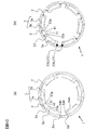
- FIG. 1 is a view of a DC motor 100 according to an embodiment of the present invention as viewed from one end.
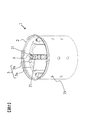
- FIG. 2 is a perspective view showing the stator 1. The configuration of the DC motor 100 will be described with reference to FIGS. 1 and 2.
- the DC motor 100 includes a stator 1 and a rotor 60.
- the rotor 60 has a shaft 62 inserted in the center.
- the rotor 60 transmits a rotational force to the outside through a shaft 62.
- a plurality of magnetic poles 3 are arranged at equal intervals on the inner periphery of a cylindrical yoke 2.
- the magnetic pole 3 includes a main magnetic pole 3a and an auxiliary magnetic pole 3b.
- the main magnetic pole 3a is made of a permanent magnet
- the auxiliary magnetic pole 3b is made of a permanent magnet or a ferromagnetic material.
- a holding member 5 is inserted between the main magnetic pole 3a and the auxiliary magnetic pole 3b.
- the magnetic pole 3 and the holding member 5 of the stator 1 extend in the axial direction of the stator 1.
- the yoke 2 is provided with an extruded portion 21 on the inner peripheral surface side by being extruded from the outer peripheral surface.
- the holding member 5 is provided with a through hole 51 (see FIG. 3). The holding member 5 is fixed to the yoke 2 by fitting the pushing portion 21 into the through hole 51.
- the magnetic pole 3 is fixed by a holding member 5. The fixing of the magnetic pole 3 by the holding member 5 will be described later.
- FIG. 3 is a view showing the holding member 5.
- the holding member 5 includes a base portion 50, a circumferential radial direction holding portion 52, an axial direction holding portion 53, and an axial direction holding portion 54.
- the base 50 has a substantially rectangular shape and is located at the center of the holding member 5.
- the longitudinal direction of the base 50 is parallel to the axial direction of the stator 1 when the holding member 5 is fixed to the stator 1.
- the axial direction holding portion 53 is a portion surrounded by a broken line region denoted by reference numeral 53, and extends from one longitudinal end of the long side of the base portion 50.
- maintenance part 53 can change the angle with the base 50 by the broken lines 530 and 531.
- maintenance part 53 is divided into the main part 53a and the bending part 53b by using these broken lines 530 and 531 as a boundary.
- the bent portion 53 b of the axial holding portion 53 has an edge portion 53 c that is held in contact with the axial end portion of the magnetic pole 3.
- the circumferential radial direction holding part 52 is a part surrounded by a broken line region denoted by reference numeral 52.
- the circumferential radial direction holding part 52 has a substantially rectangular shape and is provided adjacent to the central part of the long side of the base part 50.
- the longitudinal direction of the circumferential radial direction holding part 52 is parallel to the longitudinal direction of the base part 50.
- the circumferential direction holding part 52 can change the angle with the base part 50 by the broken lines 230 and 231.
- the axial direction holding part 54 is a part surrounded by a broken line region denoted by reference numeral 54.
- the axial direction holding portion 54 extends from one end in the longitudinal direction of the circumferential radial direction holding portion 52 and is provided by being bent along the broken line 540. Further, the axial direction holding portion 54 is divided into a main portion 54a and a bent portion 54b with a broken line 540 as a boundary.
- the above-described axial direction holding portion 53 and the axial direction holding portion 54 are located at opposite ends of the holding member 5 in the longitudinal direction.
- the magnetic pole 3 is located between the axial direction holding part 53 and the axial direction holding part 54 and is restricted from moving in the axial direction.
- FIG. 4A is a view as seen from the side in which the axial direction holding portion 54 holds the magnetic pole 3 in the axial direction of the stator 1.
- FIG. 4B is a view as seen from the side in which the axial direction holding portion 53 holds the magnetic pole 3 in the axial direction of the stator 1.
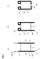
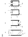
- 5A to 5C show a procedure in which the magnetic pole 3 provided on the inner peripheral surface of the stator 1 is fixed by the circumferential radial direction holding portion 52 and the axial direction holding portions 53 and 54 of the holding member 5. It is shown schematically. The illustrated vertical direction corresponds to the axial direction of the stator 1.
- the magnetic pole 3 is formed by the circumferential radial direction holding portion 52 and the axial direction holding portions 53 and 54 in the present embodiment. A procedure for manufacturing a fixing structure for fixing the substrate will be described.
- a plurality (six sets) of magnetic poles 3 (main magnetic pole 3a and auxiliary magnetic pole 3b) are arranged on the inner peripheral surface of the stator 1 in the circumferential direction. Then, the holding member 5 is inserted between the magnetic poles 3.
- the circumferential-direction radial holding portion 52 has a shape in which the end portions 52a are open until being inserted between the magnetic poles 3 (see FIG. 3).
- the holding member 5 When the holding member 5 is inserted between the magnetic poles 3, the holding member 5 comes into contact with the circumferential side surface 31 of the main magnetic pole 3 a or the circumferential side surface 41 of the auxiliary magnetic pole 3 b via the circumferential radial holding portion 52, and the inner circumferential end The load which the parts 52a approach is received. As a result, the opening angle formed by the two end portions 52a is reduced. In other words, the magnetic pole 3 is fixed in the circumferential direction and the radial direction by the elastic reaction force of the circumferential radial direction holding portion 52 against this load.
- the circumferential radial holding portion 52 of the holding member 5 As described above, when the magnetic pole 3 is fixed by the circumferential radial holding portion 52 of the holding member 5, the circumferential radial holding portion 52 of the holding member 5, as shown in FIG. It is in contact with the circumferential side surfaces 31, 41. After that, as shown in FIG. 5B, the angle of the axial holding portion 53 with respect to the base portion 50 of the holding member 5 is changed using broken lines 530 and 531 (see also FIG. 4B). The edge 53c is in contact with one end of the magnetic pole 3 in the axial direction. In this way, one end of the magnetic pole 3 in the axial direction is held by the axial edge 53 c of the axial holding portion 53. This means that the magnetic pole 3 is held by the rigidity of the axial holding portion 53.
- the circumferential radial direction holding portion 52 is bent along a broken line 540 (see FIG. 4A), so that the bent portion 54 b of the axial direction holding portion 54 has the axial direction of the magnetic pole 3. Is held at the other end.
- the axial direction holding part 54 holds the magnetic pole 3 using the elasticity of the axial direction holding part 54 by being bent.
- the elasticity of the axial holding portion 54 is generated by the cooperation of the main portion 54a and the bent portion 54b, and biases the magnetic pole 3 toward the axial holding portion 53 side.
- the magnetic pole 3 is fixed by being held by the axial holding portions 53 and 54 in the axial direction.
- the axial holding portions 53 and 54 can hold the magnetic pole 3 without a gap.
- the axial position of the broken line 540 (see the double-ended arrow 540A in FIG. 3) is determined according to the axial dimension of the magnetic pole 3. That is, the axial position of the bent portion 54 b of the axial holding portion 54 changes in accordance with the axial dimension of the magnetic pole 3. Therefore, the distance from the axial direction holding part 53 to the axial direction holding part 54 can be made equal to the axial dimension of the magnetic pole 3. This means that the magnetic pole 3 is fixed without gaps by the axial holding portions 53 and 54 in the axial direction. Accordingly, the magnetic pole 3 is caused by vibration and vibration due to rotation of the rotor 60 (FIG.
- the axial direction holding portion 53 holds the magnetic pole 3 by the edge portion 53 c being in linear contact with the magnetic pole 3.
- This holding mechanism uses the rigidity of the axial holding portion 53 itself.
- the axial direction holding part 54 holds the magnetic pole 3 by the bent part 54 b of the axial direction holding part 54.
- This holding mechanism uses the elasticity (elastic force) of the axial holding portion 54 by bending when the axial holding portion 54 is provided.
- the elasticity of the axial holding portion 54 is generated by the cooperation of the main portion 54a and the bent portion 54b, and biases the magnetic pole 3 toward the axial holding portion 53 side.
- the fixing force (holding strength) due to rigidity is larger than the elastic fixing force. Therefore, the force for fixing the magnetic pole 3 of the axial direction holding portion 53 is larger than that of the axial direction holding portion 54.
- the axial end portion of the magnetic pole 3 that receives a larger force is held by the axial holding portion 53 to prevent the magnetic pole 3 from being displaced and direct current is applied.
- the reliability of the electric motor 100 can be improved.
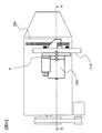
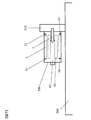
- FIG. 6 shows an example in which the axial force received by the magnetic pole 3 is biased.
- FIG. 7 is a cross-sectional view taken along the line AA of FIG. 6, and is a schematic view showing the periphery of the DC motor 100.
- the engine 200 includes a DC motor 100 that is an engine starting motor. Only one end in the axial direction of the DC motor 100 is fixed to the mounting portion 210 of the engine 200 and is cantilevered. Further, as indicated by an arrow F in FIGS. 6 and 7, the shaft 62 of the rotor 60 of the DC motor 100 receives an axial force F (axial movement force F) directed to the side opposite to the mounting portion 210 side. Then, it is pushed to the side opposite to the mounting part 210 side. Due to the shaft 62 being pushed to the side opposite to the mounting part 210 side, the magnetic pole 3 receives an axial force directed to the mounting part 210 side.
- F axial movement force
- the holding portion that holds the magnetic pole 3 on the side close to the mounting portion 210 has an axial holding portion 53 that has a larger fixing force (holding strength) than the axial holding portion 54. It is desirable to make it. By making the holding portion closer to the mounting portion 210 the axial holding portion 53 and the holding portion farther from the mounting portion 210 the axial holding portion 54, it is possible to prevent the magnetic pole 3 from being displaced in the axial direction. The reliability of the electric motor 100 can be improved.
- the stator 1 is in contact with the cylindrical yoke 2, the magnetic pole 3 (main magnetic pole 3 a, auxiliary magnetic pole 3 b) provided on the inner peripheral surface of the yoke 2, and one axial end of the magnetic pole 3.
- An axial holding portion 54 that restricts movement of the magnetic pole 3 toward one end side in the axial direction, and an axis that contacts the other axial end of the magnetic pole 3 and restricts movement of the magnetic pole 3 toward the other axial end side by its own rigidity
- the axial direction holding part 54 has an elastic force that urges the magnetic pole 3 toward the other end side in the axial direction.
- the axial direction holding part 54 has a main part 54 a and a bent part 54 b that are bent at a broken line 540 that is a boundary line perpendicular to the axial direction and separated by the bent line 540.
- the above-described elastic force is an elastic force generated by the cooperation of the main portion 54a and the bent portion 54b. As a result, even if the axial dimension of the magnetic pole 3 varies, the magnetic pole 3 can be held and fixed in the axial direction without any gaps.
- the axial holding portion 53 of the present invention is provided at both ends in the axial direction of the holding member, so that the holding position in the axial direction cannot be adjusted, and the magnetic pole There is a possibility that a gap is formed between the holding member and the holding member.
- the magnetic pole 3 can be moved in the axial direction even if the axial dimension of the magnetic pole 3 varies. It can be held and fixed without gaps.
- the axial direction holding part 53 has a main part 53a and a bent part 53b which are bent at broken lines 530 and 531 which are boundary lines parallel to the axial direction, and are divided by the bent lines 530 and 531.
- the magnetic pole 3 has an edge 53c that is in linear contact with the other axial end of the magnetic pole 3 and holds it with its own rigidity. Generally, rigidity has higher holding strength than elasticity. As a result, when the axial force received by the magnetic pole 3 is biased, the axial end of the magnetic pole 3 that receives a larger force is used as the axial holding portion 53, so that the axial position of the magnetic pole 3 is increased. Misalignment can be prevented.
- the axial position of the broken line 540 of the axial direction holding portion 54 is determined according to the axial dimension of the magnetic pole 3. Thereby, the position in the axial direction of the broken line 540 for providing the axial holding portion 54 can be adjusted and determined in accordance with the axial dimension of the magnetic pole 3. As a result, the magnetic pole 3 can be held and fixed without any gap in the axial direction.
- the stator 1 further includes a holding member 5 provided on the inner peripheral surface of the yoke 2.
- the holding member 5 includes axial direction holding portions 53 and 54 and a circumferential direction radial direction holding portion 52.
- the axial holding portions 53 and 54 restrict the movement of the magnetic pole 3 in the axial direction. Movement in the circumferential direction and the radial direction of the magnetic pole 3 is restricted by the circumferential radial direction holding portion 52.
- the DC motor 100 includes the stator 1 and the rotor 60 to which the shaft 62 is attached to the engine 200 via the attachment portion 210.
- the shaft 62 receives an axial movement force on the side opposite to the attachment portion 210 side.
- the axial direction holding part 54 is located closer to the attachment part 210 than the axial direction holding part 53.
- the holding portion that holds the axial end of the magnetic pole 3 closer to the mounting portion 210 receives a larger force.
- FIGS. 8A to 8D are diagrams showing a modified example of the procedure for manufacturing the fixing structure of the holding member 5.
- the axial direction holding parts 53 and 54 are provided by the bending method as shown in FIG.
- FIG. 5 Although it is possible to fix the magnetic pole 3 even by the bending method shown in FIG. 5, there is a possibility that a gap is caused by the spring back at the tip side of the axial holding portion 54. Shown by example. Even if the spring back described above occurs, there is no problem because the magnetic pole 3 is held by the bent portion 54b of the axial holding portion 54 on the side close to the broken line 540.
- FIG. 8A the holding member 5 is arranged and fixed so that the circumferential radial holding part 52 of the holding member 5 is along the region (square indicated by a broken line) where the magnetic pole 3 is arranged. To do.
- the holding member 5 is bent along the fold line with a large bending displacement, and the axial holding portion 54 is provided.
- the reason why the bending displacement is increased is to prevent the above-described spring back.
- the position of the broken line 540 is determined according to the axial dimension of the magnetic pole 3 to be arranged.
- the magnetic pole 3 is rubbed between the holding members 5 from the axial direction holding
- the end portions 52a (see FIG. 3) of the two circumferential radial direction holding portions 52 included in one holding member 5 are deformed so as to be close to each other so that the magnetic pole 3 is rubbed.
- the magnetic pole 3 is pushed back until it reaches the region where the magnetic pole 3 is disposed (see FIGS. 8A and 8B).
- the angle of the axial holding portion 53 with respect to the base portion 50 of the holding member 5 is changed using the bent lines 530 and 531, and the edge of the axial holding portion 53 is finally reached.
- the part 53 c is brought into contact with one end of the magnetic pole 3 in the axial direction.
- the magnetic pole 3 may be pushed back in the direction opposite to the rubbing direction by the axial holding portion 54, the axial holding portion 53 is maintained while maintaining the position where the magnetic pole 3 is to be disposed. It is necessary to provide it.
- the gap formed by the axial holding portions 53 and 54 and the magnetic pole 3 can be eliminated from the embodiment.
- the holding member 5 is arranged on the inner peripheral surface of the stator 1, it is preliminarily aligned with the axis dimension of the magnetic pole 3 along the broken line 540.
- the axial holding portion 54 may be provided by bending with a bending displacement considering the spring back, and then disposed on the inner peripheral surface of the stator 1.
- FIG. 9A is a view showing a modification of the axial direction holding portion 53.
- FIG. 9B is a BB cross-sectional view of FIG.
- one end of the magnetic pole 3 in the axial direction is held by the axial holding portion 53 of the holding member 5, but as shown in FIG. 9A, the axial holding portion 53 of the holding member 5.
- one end of the magnetic pole 3 in the axial direction can be held by the axial holding portion 70 provided integrally with the yoke 2.
- maintenance part 70 can be produced by pushing out toward the inner peripheral side from the outer peripheral side of the yoke 2, as shown in FIG.9 (b), for example. Even in the axial direction holding part 70 manufactured in this way, similarly to the axial direction holding part 53, one end of the magnetic pole 3 in the axial direction can be held by its own rigidity.
- the magnetic pole 3 is composed of the main magnetic pole 3a and the auxiliary magnetic pole 3b.
- the magnetic pole 3 can be composed of only the main magnetic pole 3a. The same effects as those of the embodiment are obtained.
- the broken line 540 is assumed to be bent perpendicular to the axial direction. Further, the broken lines 530 and 531 are bent in parallel to the axial direction. However, the axial direction holding parts 53 and 54 can restrict the movement of the magnetic pole 3 in the axial direction even if it is not strictly parallel or perpendicular to the axial direction.
- Stator 2 yoke 3: magnetic pole 3 a: main magnetic pole 3 b: auxiliary magnetic pole 5: holding member 21: push-out part 31, 41: circumferential side surface 50: base 51: through hole 52: circumferential radial holding part 53 : Axial direction holding part 53a: main part 53b: bent part 53c: edge part 54: axial direction holding part 54a: main part 54b: bent part 60: rotor 62: shaft 70: axial direction holding part 100: DC motor 200: Engine 210: Mounting portion F: Axial moving force
Landscapes
- Engineering & Computer Science (AREA)
- Power Engineering (AREA)
- Dc Machiner (AREA)
- Permanent Field Magnets Of Synchronous Machinery (AREA)
- Iron Core Of Rotating Electric Machines (AREA)
Abstract
磁極と保持部の軸方向における隙間をなくす直流電動機用固定子及び直流電動機の提供を課題とする。 この課題を解決するため、直流電動機100の固定子1を、筒状の継鉄2と、継鉄2の内周面に設けられた磁極3(主磁極3a、補磁極3b)と、磁極3の軸方向一端に接し、磁極3が軸方向一端側へ移動することを規制する軸方向保持部54と、磁極3の軸方向他端に接し、磁極3が軸方向他端側へ移動することを自身の剛性で規制する軸方向保持部53と、を備えるように構成する。また、軸方向保持部54を、磁極3を軸方向他端側へ付勢する弾性力を有するように構成する。
Description
本発明は、直流電動機用固定子及び直流電動機に関する。
固定子磁極(以下、磁極)に永久磁石を用いた直流電動機において、磁極を継鉄に固定するための構造として特許文献1に示される直流電動機がある。この直流電動機では、保持部材を用いて磁極を固定している。具体的には、保持部材の弾性反力によって、磁極の径方向への移動を規制している。また、保持部材の両端に設けられたコの字形状に折り開いた構造の縁部によって、磁極の軸方向の移動を規制している。
磁極に用いられる永久磁石は、寸法ばらつきが比較的大きい。よって、特許文献1に記載の発明では、組立て時の保持部材と磁極の干渉を防止するために、保持部材の軸方向両端に設けられたコの字形状の縁部同士の距離を、磁極の軸方向寸法ばらつきを考慮したものにする必要がある。
そのため、多くの場合、組み立て後の固定子において、軸方向において、磁極と保持部材の間に隙間が生じる虞がある。そして、これは、電機子の回転による振動、電機子反作用、直流電動機が取り付けられている装置からの振動などによって磁極が軸方向に移動することにつながる可能性がある。さらには、磁極と電機子が磁気的に干渉したり、固定子と電機子の磁気中心がずれたりすることによる、電動機の出力低下や異音の発生の原因となる可能性がある。
本発明による直流電動機用固定子は、筒状の継鉄と、継鉄の内周面に設けられた磁極と、磁極の軸方向一端に接し、磁極が軸方向一端側へ移動することを規制する第1保持部と、磁極の軸方向他端に接し、磁極が軸方向他端側へ移動することを自身の剛性で規制する第2保持部と、を備える。第1保持部は、磁極を軸方向他端側へ付勢する弾性力を有している。
本発明によれば、磁極の軸方向寸法ばらつきに適応して、保持部と磁極を軸方向に隙間無く組み立てることができる。その結果、電機子の回転による振動、電機子反作用、直流電動機が取り付けられている装置からの振動などによって磁極が軸方向に移動することを防止できる。さらには、磁極と電機子が干渉したり、固定子と電機子の磁気中心がずれたりすることによる、電動機の出力低下や異音の発生を防止することができる。
―実施形態―
図1は、本発明の一の実施形態である直流電動機100を一端から見た図である。図2は、固定子1を示す斜視図である。図1及び図2を用いて、直流電動機100の構成について説明する。
図1は、本発明の一の実施形態である直流電動機100を一端から見た図である。図2は、固定子1を示す斜視図である。図1及び図2を用いて、直流電動機100の構成について説明する。
図1に示すように、直流電動機100は、固定子1と、回転子60とから構成される。回転子60は、中央部にシャフト62が挿設されている。回転子60は、シャフト62によって、回転力を外部に伝達する。固定子1は、円筒状の継鉄2の内周に、磁極3が等間隔に複数配置されている。磁極3は、主磁極3aと補磁極3bから構成される。主磁極3aは永久磁石で、補磁極3bは永久磁石または強磁性体で作製されている。主磁極3a及び補磁極3bの間には保持部材5が挿入されている。
図2に示すように、固定子1の磁極3及び保持部材5は、固定子1の軸方向に延在している。継鉄2には、外周面から押し出されることで内周面側に押出部21が設けられている。保持部材5には、貫通孔51(図3参照)が設けられている。この貫通孔51に押出部21が嵌合することで保持部材5が継鉄2に固定されている。磁極3は、保持部材5によって固定されている。保持部材5による磁極3の固定については、後述する。
図3は、保持部材5を示す図である。保持部材5は、基部50、周方向径方向保持部52、軸方向保持部53、および、軸方向保持部54を有する。基部50は、略長方形の形状を有しており、保持部材5の中央に位置している。基部50の長手方向は、保持部材5が固定子1と固定される際、固定子1の軸方向と平行となる。軸方向保持部53は、符号53を付した破線領域に囲まれる部位であり、基部50の長辺の長手方向一端から延設されている。軸方向保持部53は、折れ線530、531によって、基部50との角度を変化させることができる。また、軸方向保持部53は、これらの折れ線530,531を境にして、主部53aと折り曲げ部53bに分けられる。軸方向保持部53の折り曲げ部53bは、磁極3の軸方向の端部と接して保持する縁部53cを有する。周方向径方向保持部52は、符号52を付した破線領域に囲まれる部位である。周方向径方向保持部52は、略長方形の形状を有しており、基部50の長辺の中央部に隣接して設けられている。周方向径方向保持部52の長手方向は、基部50の長手方向と平行となっている。周方向径方向保持部52は、折れ線230、231によって、基部50との角度を変化させることができる。軸方向保持部54は、符号54を付した破線領域に囲まれる部位である。軸方向保持部54は、周方向径方向保持部52の長手方向一端から延設されており、折れ線540に沿って折り曲げられることで設けられる。また、軸方向保持部54は、折れ線540を境にして、主部54aと折り曲げ部54bに分けられる。なお、図に示すように、上述の軸方向保持部53と軸方向保持部54は、保持部材5の長手方向における対向する端部に位置する。固定子1において、磁極3は、軸方向保持部53と軸方向保持部54の間に位置して、軸方向の移動を規制される。
図4(a)は、固定子1の軸方向において軸方向保持部54が磁極3を保持している側から見た図である。図4(b)は、固定子1の軸方向において軸方向保持部53が磁極3を保持している側から見た図である。
図5(a)~(c)は、固定子1の内周面に設けられた磁極3を、保持部材5の周方向径方向保持部52、軸方向保持部53、54が固定する手順を模式的に示したものである。図示上下方向が固定子1の軸方向に対応する。
以下に、図4(a)、(b)、及び、図5(a)~(c)を用いて、本実施形態における周方向径方向保持部52、軸方向保持部53、54によって磁極3を固定する固定構造の作製手順について説明する。
まず、図4(a)、(b)に示すように、固定子1の内周面に磁極3(主磁極3a、補磁極3b)を周方向に複数(6組)配置する。そして、磁極3の間に保持部材5を挿入する。周方向径方向保持部52は、磁極3の間に挿入されるまでは、端部52a同士が開いた形状となっている(図3参照)。保持部材5は、磁極3の間に挿入されると、周方向径方向保持部52を介して主磁極3aの周方向側面31または補磁極3bの周方向側面41と当接し、内周側端部52a同士が近づくような荷重を受ける。その結果、2つの端部52aで構成される開き角が小さくなる。すなわち、磁極3は、周方向及び径方向において、この荷重に対する周方向径方向保持部52の弾性反力によって固定される。
上述のように磁極3が保持部材5の周方向径方向保持部52によって固定される際、保持部材5の周方向径方向保持部52は、図5(a)に示すように、磁極3の周方向側面31,41に当接している。その上で、図5(b)に示すように、折れ線530,531(図4(b)も参照)を用いて、保持部材5の基部50に対する軸方向保持部53の角度を変化させる。そして、磁極3の軸方向の一端に縁部53cが接するようにする。このようにして、軸方向保持部53の軸方向の縁部53cで磁極3の軸方向の一端が保持される。これは、軸方向保持部53の剛性によって磁極3が保持されることを意味する。さらに、図5(c)に示すように、周方向径方向保持部52を折れ線540(図4(a)参照)で折り曲げることで、軸方向保持部54の折り曲げ部54bで磁極3の軸方向のもう一端が保持される。軸方向保持部54は、折り曲げられることによる軸方向保持部54の弾性を利用して磁極3を保持する。軸方向保持部54の弾性は、主部54aと折り曲げ部54bが協働して生成するものであり、磁極3を軸方向保持部53側に付勢するものである。
このようにして、磁極3は、軸方向において、軸方向保持部53,54で保持されることで固定される。その結果、磁極3の軸方向の移動が規制される。また、軸方向保持部54の弾性により、軸方向保持部53,54は、隙間なく磁極3を保持することができる。
このようにして、磁極3は、軸方向において、軸方向保持部53,54で保持されることで固定される。その結果、磁極3の軸方向の移動が規制される。また、軸方向保持部54の弾性により、軸方向保持部53,54は、隙間なく磁極3を保持することができる。
なお、折れ線540の軸方向位置(図3の両端矢印540A参照)は磁極3の軸方向寸法に合わせて決定される。すなわち、軸方向保持部54の折り曲げ部54bの軸方向位置が、磁極3の軸方向寸法に合わせて変化する。よって、軸方向保持部53から軸方向保持部54の距離を磁極3の軸方向寸法と等しくすることができる。これは、すなわち、磁極3が、軸方向において、軸方向保持部53,54によって隙間なく固定されること意味する。
これによって、固定子1の内側に配置される電機子である回転子60(図1)の回転による振動や振れ、電機子反作用、直流電動機100が取り付けられている装置からの振動などによって磁極3が軸方向に移動することを防止できる。その結果、固定子1と回転子60の磁気中心がずれることによる、直流電動機100の出力低下や異音の発生を防止することができる。
これによって、固定子1の内側に配置される電機子である回転子60(図1)の回転による振動や振れ、電機子反作用、直流電動機100が取り付けられている装置からの振動などによって磁極3が軸方向に移動することを防止できる。その結果、固定子1と回転子60の磁気中心がずれることによる、直流電動機100の出力低下や異音の発生を防止することができる。
軸方向保持部53は、縁部53cが磁極3に線状に接することで、磁極3を保持している。この保持機構は、軸方向保持部53自身の剛性を利用している。一方、軸方向保持部54は、磁極3を軸方向保持部54の折り曲げ部54bで保持している。この保持機構は、軸方向保持部54が設けられるときの折り曲げによる軸方向保持部54の弾性(弾性力)を利用している。軸方向保持部54の弾性は、主部54aと折り曲げ部54bが協働して生成するものであり、磁極3を軸方向保持部53側に付勢するものである。同一材質の場合、一般的に、剛性による固定力(保持強度)は、弾性の固定力よりも大きい。よって、軸方向保持部53の磁極3を固定する力は、軸方向保持部54のそれよりも大きい。
そのため、磁極3が受ける軸方向の力に偏りがある場合、より大きい力を受ける磁極3の軸方向端部を軸方向保持部53で保持することで、磁極3の位置ずれを防止して直流電動機100の信頼性を向上させることができる。
図6は、磁極3が受ける軸方向の力に偏りがある一例を示している。図7は、図6のA-A断面図であり、直流電動機100の周辺を示した概略図である。エンジン200は、エンジン始動用電動機である直流電動機100を有している。直流電動機100は、軸方向の一端のみがエンジン200の取付部210に固定されており、片持ちとなっている。さらに、図6、7の矢印Fで示すように、直流電動機100の回転子60のシャフト62は、取付部210側と反対側に向いた軸方向の力F(軸方向移動力F)を受け、取付部210側と反対側に押される。シャフト62が取付部210側と反対側に押されることに起因して、磁極3は取付部210側に向いた軸方向の力を受ける。
このような場合において、取付部210に近い側の磁極3を保持する保持部は、図7に示したように、軸方向保持部54よりも固定力(保持強度)が大きい軸方向保持部53にすることが望ましい。取付部210に近い側の保持部を軸方向保持部53にし、取付部210に遠い側の保持部を軸方向保持部54にすることによって、磁極3が軸方向にずれることを防止でき、直流電動機100の信頼性を向上できる。
上述した実施の形態によれば、次の作用効果が得られる。
(1)固定子1は、筒状の継鉄2と、継鉄2の内周面に設けられた磁極3(主磁極3a、補磁極3b)と、磁極3の軸方向一端に接し、磁極3が軸方向一端側へ移動することを規制する軸方向保持部54と、磁極3の軸方向他端に接し、磁極3が軸方向他端側へ移動することを自身の剛性で規制する軸方向保持部53と、を備え、軸方向保持部54は、磁極3を軸方向他端側へ付勢する弾性力を有している。
軸方向保持部54は、軸方向に垂直な境界線である折れ線540で折り曲げられ、折れ線540で区切られる主部54aと折り曲げ部54bとを有する。上述の弾性力は、主部54aと折り曲げ部54bとが協働して生成する弾性力である。
これによって、磁極3の軸方向寸法のばらつきがあっても、軸方向において磁極3を隙間なく保持し、固定することができる。
特許文献1に記載の発明では、本発明の軸方向保持部53に相当するものが、保持部材の軸方向の両端に設けられているため、軸方向の保持する位置の調節ができず、磁極と保持部材との間に隙間ができる可能性がある。
しかし、上述のように、本発明においては保持部材5の軸方向の一方が軸方向保持部54となっているため、磁極3の軸方向寸法のばらつきがあっても、軸方向において磁極3を隙間なく保持し、固定することができる。
しかし、上述のように、本発明においては保持部材5の軸方向の一方が軸方向保持部54となっているため、磁極3の軸方向寸法のばらつきがあっても、軸方向において磁極3を隙間なく保持し、固定することができる。
(2)軸方向保持部53は、軸方向に平行な境界線である折れ線530、531で折り曲げられ、折れ線530、531で区切られる主部53aと折り曲げ部53bとを有し、折り曲げ部53bは、磁極3の軸方向他端に線状に接して自身の剛性で保持する縁部53cを有する。一般的に、剛性は、弾性よりも保持強度が高い。
これによって、磁極3が受ける軸方向の力に偏りがある場合には、より大きな力を受ける磁極3の軸方向端部を、軸方向保持部53にすることで、磁極3の軸方向の位置ずれを防止できる。
これによって、磁極3が受ける軸方向の力に偏りがある場合には、より大きな力を受ける磁極3の軸方向端部を、軸方向保持部53にすることで、磁極3の軸方向の位置ずれを防止できる。
(3)軸方向保持部54の折れ線540の軸方向位置は、磁極3の軸方向寸法に合わせて決定される。
これによって、磁極3の軸方向寸法に合わせて軸方向保持部54を設けるための折れ線540の軸方向の位置を調節し決定することができる。その結果、軸方向において磁極3を隙間なく保持し、固定することができる。
これによって、磁極3の軸方向寸法に合わせて軸方向保持部54を設けるための折れ線540の軸方向の位置を調節し決定することができる。その結果、軸方向において磁極3を隙間なく保持し、固定することができる。
(4)固定子1は、継鉄2の内周面に設けられる保持部材5をさらに備える。保持部材5は、軸方向保持部53、54と、周方向径方向保持部52と、を有する。
軸方向保持部53、54によって、磁極3の軸方向の移動が規制される。周方向径方向保持部52によって、磁極3の周方向及び径方向の移動が規制される。
軸方向保持部53、54によって、磁極3の軸方向の移動が規制される。周方向径方向保持部52によって、磁極3の周方向及び径方向の移動が規制される。
(5)直流電動機100は、固定子1と、エンジン200に取付部210を介してシャフト62が取り付けられる回転子60と、を備える。シャフト62は、取付部210側と反対側の軸方向移動力を受ける。軸方向保持部54は、軸方向保持部53よりも取付部210の近くに位置する。
これによって、取付部210に近い方の磁極3の軸方向端部を保持する保持部がより大きい力を受ける。その保持部を軸方向保持部53にすることで、軸方向保持部54で保持するよりも、固定力を上げることができる。その結果、磁極3の軸方向の位置ずれを防止でき、固定子と電機子の磁気中心がずれたりすることによる電動機の出力低下や異音の発生を防止することができる。それによって、直流電動機100の信頼性を向上させることができる。
これによって、取付部210に近い方の磁極3の軸方向端部を保持する保持部がより大きい力を受ける。その保持部を軸方向保持部53にすることで、軸方向保持部54で保持するよりも、固定力を上げることができる。その結果、磁極3の軸方向の位置ずれを防止でき、固定子と電機子の磁気中心がずれたりすることによる電動機の出力低下や異音の発生を防止することができる。それによって、直流電動機100の信頼性を向上させることができる。
次のような変形も本発明の範囲内であり、以下の変形例を上述の実施形態と組み合わせることも可能である。
―保持部材5の固定構造の作製手順の変形例―
図8(a)~(d)は、保持部材5の固定構造の作製手順の変形例を示す図である。
以上の実施形態では、図5に示すような折り曲げ方によって、軸方向保持部53、54を設けた。図5に示す折り曲げ方でも、磁極3を固定することは可能であるが、軸方向保持部54の先端側がスプリングバックによる隙間を生じる可能性があるため、その隙間を生じさせない折り曲げ方を本変形例で示す。なお、上述のスプリングバックが生じても、折れ線540に近い側の軸方向保持部54の折り曲げ部54bで磁極3を保持するので、問題はない。
―保持部材5の固定構造の作製手順の変形例―
図8(a)~(d)は、保持部材5の固定構造の作製手順の変形例を示す図である。
以上の実施形態では、図5に示すような折り曲げ方によって、軸方向保持部53、54を設けた。図5に示す折り曲げ方でも、磁極3を固定することは可能であるが、軸方向保持部54の先端側がスプリングバックによる隙間を生じる可能性があるため、その隙間を生じさせない折り曲げ方を本変形例で示す。なお、上述のスプリングバックが生じても、折れ線540に近い側の軸方向保持部54の折り曲げ部54bで磁極3を保持するので、問題はない。
図8(a)~(d)を用いて、本変形例での保持部材5の固定構造の作製手順について説明する。
まず、図8(a)に示すように、磁極3が配置される領域(破線で示した四角)に保持部材5の周方向径方向保持部52が沿うように、保持部材5を配置し固定する。
まず、図8(a)に示すように、磁極3が配置される領域(破線で示した四角)に保持部材5の周方向径方向保持部52が沿うように、保持部材5を配置し固定する。
次に、図8(b)に示すように、保持部材5を折れ線に沿って、折り曲げ変位を大きめに取って折り曲げて、軸方向保持部54を設ける。折り曲げ変位を大きめに取るのは、上述のスプリングバックを生じさせないためである。また、折れ線540の位置は、配置される予定の磁極3の軸寸法に従って決定される。
そして、図8(c)に示すように、保持部材5の間に磁極3を軸方向保持部53側から擦り込む。その際、1つの保持部材5が有する2つの周方向径方向保持部52の端部52a(図3参照)同士を近づけるように変形させて、磁極3が擦り込めるようにする。また、磁極3が軸方向保持部54と接触した後は、磁極3が配置される領域(図8(a)、(b)参照)に到達するまで、軸方向保持部54を押し返すように磁極3を擦り込む。
最後に、図8(d)に示すように、最後に、折れ線530,531を用いて、保持部材5の基部50に対する軸方向保持部53の角度を変化させて、軸方向保持部53の縁部53cを磁極3の軸方向の一端に接するようにする。その際、軸方向保持部54によって、磁極3が上述の擦り込む向きと逆向きに押し返される可能性があるので、磁極3の配置されるべき位置を維持しつつ、軸方向保持部53を設ける必要がある。
以上のように、保持部材5の固定構造を作製すると、軸方向保持部53、54と磁極3によってできる隙間を実施形態よりもなくすことができる。
なお、図8(a)、(b)という手順を踏む代わりに、保持部材5を固定子1の内周面に配置する前に、予め、磁極3の軸寸法に合わせて折れ線540に沿ってスプリングバックを考慮した曲げ変位で折り曲げて軸方向保持部54を設けるようにし、その後、固定子1の内周面に配置しても良い。
なお、図8(a)、(b)という手順を踏む代わりに、保持部材5を固定子1の内周面に配置する前に、予め、磁極3の軸寸法に合わせて折れ線540に沿ってスプリングバックを考慮した曲げ変位で折り曲げて軸方向保持部54を設けるようにし、その後、固定子1の内周面に配置しても良い。
―軸方向保持部53の変形例―
図9(a)は、軸方向保持部53の変形例を示す図である。図9(b)は、図9(a)のB-B断面図である。
以上の実施形態では、磁極3の軸方向の一端は、保持部材5の軸方向保持部53に保持されていたが、図9(a)に示すように、保持部材5の軸方向保持部53の代わりに、継鉄2に一体的に設けられた軸方向保持部70で磁極3の軸方向の一端を保持することもできる。軸方向保持部70は、例えば、図9(b)に示すように、継鉄2の外周側から内周側に向けて押し出して作製することができる。
このように作製された軸方向保持部70であっても、軸方向保持部53と同様に、自身の剛性によって磁極3の軸方向の一端を保持することができる。
―磁極3の構成の変形例―
以上の実施形態においては、磁極3は、主磁極3aと補磁極3bから構成されるとしたが、主磁極3aのみで磁極3を構成にすることも可能であり、その場合であっても以上の実施形態と同様の作用効果を奏する。
以上の実施形態においては、磁極3は、主磁極3aと補磁極3bから構成されるとしたが、主磁極3aのみで磁極3を構成にすることも可能であり、その場合であっても以上の実施形態と同様の作用効果を奏する。
以上では、折れ線540は軸方向に対して垂直に折れ曲がるとした。また、折れ線530,531は、軸方向に対して平行に折れ曲がるとした。しかし、厳密に軸方向に平行や垂直でなくとも、軸方向保持部53、54は磁極3の軸方向の移動を規制することができる。
本発明は、以上に示した実施形態及び変形例に限定されるものではない。本発明の技術的思想の範囲内で考えられるその他の態様も本発明の範囲内に含まれる。
1 :固定子
2 :継鉄
3 :磁極
3a:主磁極
3b:補磁極
5 :保持部材
21:押出部
31、41:周方向側面
50:基部
51:貫通孔
52:周方向径方向保持部
53:軸方向保持部
53a:主部
53b:折り曲げ部
53c:縁部
54:軸方向保持部
54a:主部
54b:折り曲げ部
60:回転子
62:シャフト
70:軸方向保持部
100:直流電動機
200:エンジン
210:取付部
F:軸方向移動力
2 :継鉄
3 :磁極
3a:主磁極
3b:補磁極
5 :保持部材
21:押出部
31、41:周方向側面
50:基部
51:貫通孔
52:周方向径方向保持部
53:軸方向保持部
53a:主部
53b:折り曲げ部
53c:縁部
54:軸方向保持部
54a:主部
54b:折り曲げ部
60:回転子
62:シャフト
70:軸方向保持部
100:直流電動機
200:エンジン
210:取付部
F:軸方向移動力
Claims (6)
- 筒状の継鉄と、
前記継鉄の内周面に設けられた磁極と、
前記磁極の軸方向の一端(以下、軸方向一端)に接し、前記磁極が軸方向一端側へ移動することを規制する第1保持部と、
前記磁極の軸方向の他端(以下、軸方向他端)に接し、前記磁極が軸方向他端側へ移動することを自身の剛性で規制する第2保持部と、を備え、
前記第1保持部は、前記磁極を前記軸方向他端側へ付勢する弾性力を有している直流電動機用固定子。 - 請求項1に記載の直流電動機用固定子において、
前記第1保持部は、前記軸方向に垂直な第1境界線で折り曲げられ、前記第1境界線で区切られる第1主部と第1折り曲げ部とを有し、
前記第1主部および前記第1折り曲げ部は、協働して前記弾性力を生成する直流電動機用固定子。 - 請求項2に記載の直流電動機用固定子において、
前記第1境界線の軸方向位置は、前記磁極の軸方向寸法に合わせて決定される直流電動機用固定子。 - 請求項1に記載の直流電動機用固定子において、
前記第2保持部は、前記軸方向に平行な第2境界線で折り曲げられ、前記第2境界線で区切られる第2主部と第2折り曲げ部とを有し、
前記第2折り曲げ部は、前記磁極の軸方向他端に線状に接して保持する縁部を有する直流電動機用固定子。 - 請求項1~4のいずれか一項に記載の直流電動機用固定子において、
前記継鉄の内周面に設けられる保持部材をさらに備え、
前記保持部材は、前記第1保持部と、前記第2保持部と、前記磁極が周方向及び径方向へ移動することを規制する第3保持部と、を有する直流電動機用固定子。 - 請求項1~4のいずれか一項に記載の直流電動機用固定子と、エンジンに取付部を介してシャフトが取り付けられる回転子と、を備える直流電動機であって、
前記シャフトは、前記取付部側と反対側の軸方向移動力を受け、
前記第2保持部は、前記第1保持部よりも前記取付部の近くに位置する直流電動機。
Priority Applications (1)
| Application Number | Priority Date | Filing Date | Title |
|---|---|---|---|
| JP2016514829A JP6311010B2 (ja) | 2014-04-22 | 2015-03-25 | 直流電動機 |
Applications Claiming Priority (2)
| Application Number | Priority Date | Filing Date | Title |
|---|---|---|---|
| JP2014-088008 | 2014-04-22 | ||
| JP2014088008 | 2014-04-22 |
Publications (1)
| Publication Number | Publication Date |
|---|---|
| WO2015163079A1 true WO2015163079A1 (ja) | 2015-10-29 |
Family
ID=54332249
Family Applications (1)
| Application Number | Title | Priority Date | Filing Date |
|---|---|---|---|
| PCT/JP2015/059024 Ceased WO2015163079A1 (ja) | 2014-04-22 | 2015-03-25 | 直流電動機用固定子及び直流電動機 |
Country Status (2)
| Country | Link |
|---|---|
| JP (1) | JP6311010B2 (ja) |
| WO (1) | WO2015163079A1 (ja) |
Citations (6)
| Publication number | Priority date | Publication date | Assignee | Title |
|---|---|---|---|---|
| JPS60187249A (ja) * | 1984-03-07 | 1985-09-24 | Hitachi Ltd | 磁石式直流機用固定子 |
| JPH0511755U (ja) * | 1991-07-24 | 1993-02-12 | 自動車電機工業株式会社 | モータマグネツト用リテーナ |
| JPH06327207A (ja) * | 1993-04-14 | 1994-11-25 | Johnson Electric Sa | 磁石スペーサを有するpmdc電気モータ |
| JPH09168245A (ja) * | 1995-12-15 | 1997-06-24 | Hitachi Ltd | 磁石式直流機の固定子 |
| JP2007500497A (ja) * | 2003-05-30 | 2007-01-11 | ヴァレオ エキプマン エレクトリク モトゥール | 電動モータの界磁コイルとしての円筒ケーシングの内部にある永久磁石を固定する装置 |
| JP2010514398A (ja) * | 2006-12-19 | 2010-04-30 | ローベルト ボツシユ ゲゼルシヤフト ミツト ベシユレンクテル ハフツング | ポールケーシングアッセンブリ |
-
2015
- 2015-03-25 WO PCT/JP2015/059024 patent/WO2015163079A1/ja not_active Ceased
- 2015-03-25 JP JP2016514829A patent/JP6311010B2/ja active Active
Patent Citations (6)
| Publication number | Priority date | Publication date | Assignee | Title |
|---|---|---|---|---|
| JPS60187249A (ja) * | 1984-03-07 | 1985-09-24 | Hitachi Ltd | 磁石式直流機用固定子 |
| JPH0511755U (ja) * | 1991-07-24 | 1993-02-12 | 自動車電機工業株式会社 | モータマグネツト用リテーナ |
| JPH06327207A (ja) * | 1993-04-14 | 1994-11-25 | Johnson Electric Sa | 磁石スペーサを有するpmdc電気モータ |
| JPH09168245A (ja) * | 1995-12-15 | 1997-06-24 | Hitachi Ltd | 磁石式直流機の固定子 |
| JP2007500497A (ja) * | 2003-05-30 | 2007-01-11 | ヴァレオ エキプマン エレクトリク モトゥール | 電動モータの界磁コイルとしての円筒ケーシングの内部にある永久磁石を固定する装置 |
| JP2010514398A (ja) * | 2006-12-19 | 2010-04-30 | ローベルト ボツシユ ゲゼルシヤフト ミツト ベシユレンクテル ハフツング | ポールケーシングアッセンブリ |
Also Published As
| Publication number | Publication date |
|---|---|
| JP6311010B2 (ja) | 2018-04-11 |
| JPWO2015163079A1 (ja) | 2017-04-13 |
Similar Documents
| Publication | Publication Date | Title |
|---|---|---|
| JP5920637B2 (ja) | 回転電機の回転子 | |
| JP6042302B2 (ja) | モータ | |
| JP6238054B2 (ja) | インナーロータ型モータ | |
| JP2010263689A (ja) | 電動モータ、および減速機付モータ | |
| US20190229576A1 (en) | Rotary electric machine and stator | |
| JP2016129473A (ja) | モータ | |
| JP2014138434A (ja) | モータ | |
| CN111193339A (zh) | 车辆用电动机 | |
| CN115943541B (zh) | 旋转电机及旋转电机的制造方法 | |
| JP2013514754A (ja) | 電気モータ | |
| JP2010093939A (ja) | 電動モータ | |
| JP2015163038A (ja) | インナーロータ型ブラシレスモータ | |
| JP6147226B2 (ja) | 回転電機用ロータ | |
| JP5727577B2 (ja) | コイル固定部品を備える電動機の固定子、電動機、及び単位コイルの固定方法 | |
| WO2018179736A1 (ja) | ロータ及びロータを備えたモータ | |
| JP6311010B2 (ja) | 直流電動機 | |
| JP2012044789A (ja) | 回転電機およびその製造方法 | |
| JP5953143B2 (ja) | 直流電動機の製造方法 | |
| JP6285295B2 (ja) | 減速機付モータ及び減速機付モータの組立方法 | |
| CN109728702B (zh) | 车用电机 | |
| JP6040014B2 (ja) | モータ | |
| JP2018107839A (ja) | 回転電機用固定子コア及び固定子、並びに回転電機 | |
| WO2019064747A1 (ja) | ロータ及びそのロータを備えたモータ | |
| JP2007330084A (ja) | ロータ | |
| JP7234813B2 (ja) | モータ |
Legal Events
| Date | Code | Title | Description |
|---|---|---|---|
| 121 | Ep: the epo has been informed by wipo that ep was designated in this application |
Ref document number: 15783797 Country of ref document: EP Kind code of ref document: A1 |
|
| ENP | Entry into the national phase |
Ref document number: 2016514829 Country of ref document: JP Kind code of ref document: A |
|
| NENP | Non-entry into the national phase |
Ref country code: DE |
|
| 122 | Ep: pct application non-entry in european phase |
Ref document number: 15783797 Country of ref document: EP Kind code of ref document: A1 |