WO2015159796A1 - タイヤ - Google Patents
タイヤ Download PDFInfo
- Publication number
- WO2015159796A1 WO2015159796A1 PCT/JP2015/061118 JP2015061118W WO2015159796A1 WO 2015159796 A1 WO2015159796 A1 WO 2015159796A1 JP 2015061118 W JP2015061118 W JP 2015061118W WO 2015159796 A1 WO2015159796 A1 WO 2015159796A1
- Authority
- WO
- WIPO (PCT)
- Prior art keywords
- tire
- sipe
- inclined portion
- width direction
- tire width
- Prior art date
- Legal status (The legal status is an assumption and is not a legal conclusion. Google has not performed a legal analysis and makes no representation as to the accuracy of the status listed.)
- Ceased
Links
Images
Classifications
-
- B—PERFORMING OPERATIONS; TRANSPORTING
- B60—VEHICLES IN GENERAL
- B60C—VEHICLE TYRES; TYRE INFLATION; TYRE CHANGING; CONNECTING VALVES TO INFLATABLE ELASTIC BODIES IN GENERAL; DEVICES OR ARRANGEMENTS RELATED TO TYRES
- B60C11/00—Tyre tread bands; Tread patterns; Anti-skid inserts
- B60C11/03—Tread patterns
- B60C11/12—Tread patterns characterised by the use of narrow slits or incisions, e.g. sipes
Definitions
- the present invention relates to a tire in which a sipe is formed on the tire tread side of a block, and more particularly, to a tire with improved running performance on snow.
- a lug groove extending in a direction intersecting the circumferential groove is provided, and a sipe is provided on the surface of the block defined by the circumferential groove and the lug groove.
- Many formed are used (see, for example, Patent Document 1).
- the inclination angle of the lug groove with respect to the tire width direction is set within a range of ⁇ 5 ° to ⁇ 45 °, and a sipe extending in a direction parallel to the tire width direction is formed, thereby braking on snow.
- the skid resistance on snow can be improved without deteriorating the traction performance.
- the present invention has been made in view of the conventional problems, and an object thereof is to provide a tire capable of improving both snow traction performance and snow handling performance.
- the present invention includes a circumferential groove formed on a tread surface so as to extend along a tire circumferential direction, a lug groove extending in a direction intersecting with the circumferential groove, and the circumferential groove and the lug groove.
- a tire including a plurality of partitioned blocks, wherein the block partitioned by the circumferential groove and the lug groove among the plurality of blocks is provided on the inner side in the tire width direction of the block, and has one end Are provided in the circumferential groove or the lug groove, and the other end is provided inside the block, and is provided on the outer side in the tire width direction from the end of the first inclined part.
- a sipe having a second inclined portion extending in a direction opposite to the starting end side of the inclined portion is formed, and an angle (sipe) formed by an extension direction of the second inclined portion and a direction parallel to the tire width direction is formed.
- the inclination angle) is the sipe of the first inclined portion. Characterized in that less than oblique angle. In this way, by increasing the inclination angle inside the tire width direction of the sipe, while ensuring block rigidity, the front and rear and side edge effects are exhibited, and the inclination angle inside the tire width direction of the sipe is reduced to reduce lateral input. Since the block edge pressure is increased, both snow traction performance and snow handling performance can be improved.
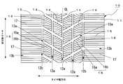
- FIG. 1 is a diagram illustrating an example of a tread pattern of a tire 10 according to the present embodiment, in which the vertical direction is the tire circumferential direction and the horizontal direction is the tire width direction.
- 11 is a tread
- 12a and 12b are circumferential grooves formed so as to extend along the tire circumferential direction on the tread surface side of the tread 11
- 13a and 13b are in a direction intersecting the circumferential grooves 12a and 12b. It is a lug groove extending along.
- the circumferential groove located on the inner side in the tire width direction is the inner main groove 12a
- the circumferential groove located on the outer side in the tire width direction is the shoulder groove 12b
- the extending lug groove is referred to as an inclined lug groove 13a
- the lug groove extending from the shoulder groove 12b toward the outer side in the tire width direction is referred to as a shoulder lug groove 13b.
- Reference numeral 14 denotes an inner block defined by the inner main groove 12a and the inclined lug groove 13a.
- Reference numeral 15 denotes a shoulder block defined by the shoulder groove 12b and the shoulder lug groove 13b.
- a first sipe 16 is formed on the tire block
- a second sipe 17 is formed on the tire tread surface side of the shoulder block 15.
- the inclined lug groove 13a is inclined with respect to both the tire circumferential direction and the tire width direction. Specifically, the inclined lug groove 13a located on the right side of the center line CL extends continuously upward from the inner main groove 12a located in the center in the tire width direction to the shoulder lug groove 13b located on the right side in the tire width direction. The inclined lug groove 13a located on the left side of CL extends continuously downward from the inner main groove 12a located at the center in the tire width direction to the shoulder lug groove 13b located on the left side in the tire width direction. As shown in FIG.
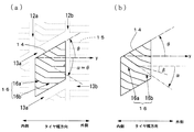
- an angle (hereinafter referred to as an inclined lug groove angle) ⁇ between the right inclined lug groove 13a and the tire width direction indicated by the y-axis direction in the figure is defined.
- the angle of the inclined lug groove ⁇ measured counterclockwise from the y axis is (+).
- the inclined lug groove angle of the right inclined lug groove 13a is 30 °
- the inclined lug groove angle of the left inclined lug groove 13a is ⁇ 30 °.
- the shoulder lug groove 13b extends in the direction parallel to the tire width direction from the shoulder groove 12b toward the outer side in the tire width direction, and opens to the outer side of the tire tread surface.
- the lug groove angle of the shoulder lug groove 13b is 0 °.
- the first sipe 16 is a sipe having a broken line shape in plan view, and includes a first inclined portion 16a located on the inner side in the tire width direction and a second inclined portion 16b located on the outer side in the tire width direction.
- One end of the first inclined portion 16 a opens into the inner main groove 12 a or the inclined lug groove 13 a and the other end terminates in the inner block 14.
- the second inclined portion 16b extends from the end of the first inclined portion 16a as a starting end in the direction opposite to the first inclined portion 16a (leftward if the first inclined portion 16a is rightward), The other end opens to the inclined lug groove 13a or the shoulder groove 12b.
- the second sipe 17 is a sipe extending in a direction parallel to the tire width direction, and the sipe angle is 0 °.
- the first inclined portion 16a of the first sipe 16 is inclined in a direction opposite to the inclined lug groove 13a that defines the inner block 14 in which the first sipe 16 is formed. That is, in the first sipe 16 provided in the right inner block 14, the slope of the first inclined portion 16 a is lowered to the right, and in the first sipe 16 provided in the left inner block 14, it is lowered to the left. is there.
- the angle ⁇ between the extending direction of the first inclined portion 16a and the direction parallel to the tire width direction (hereinafter referred to as the inner sipe angle) ⁇ may be in the range of ⁇ 15 ° to ⁇ 45 °. preferable.
- the extending direction of the second inclined portion 16b is parallel to the tire width direction. That is, an angle ⁇ (hereinafter referred to as an outer sipe angle) ⁇ formed by the extending direction of the second inclined portion 16b and a direction parallel to the tire width direction is 0 °. Therefore, of the first sipe 16, the first sipe 16 in which the second inclined portion 16b is open to the shoulder groove 12b is orthogonal to the shoulder groove 12b in the second inclined portion 16b.
- the sipe angle is 0 °, that is, the extension direction of the sipe is parallel to the tire width direction because the edge component in the front-rear direction increases.
- the influence on the lateral input is larger outside the block in the tire width direction.
- the first sipe 16 has the outer sipe angle ⁇ of 0 °, the lateral rigidity of the inner block 14 can be increased, and the edge effect of the traction (front and rear edge effect) can be achieved. Can be increased. That is, the first sipe 16 formed on the tread surface side of the inner block 14 is positioned on the inner side in the tire width direction, and the first inclined portion 16a is inclined in the direction opposite to the inclined lug groove 13a, and the outer side in the tire width direction.
- the first inclined portion 16a is inclined in the direction opposite to the inclined lug groove 13a so as to increase the rigidity with respect to the input of the inner block 14 from the oblique direction (particularly, the direction substantially orthogonal to the inclined lug groove 13a). Therefore, the snow traction performance and snow handling performance can be further improved.
- the extension direction of the second inclined portion is parallel to the tire width direction, so that the block edge pressure with respect to the lateral input is further increased, so that the handling performance on snow can be further improved.
- the lug groove is inclined with respect to both the tire circumferential direction and the tire width direction, and the first inclined portion of the sipe is opposite to the inclination direction of the lug groove (if the lug groove is raised to the right) Therefore, the traction performance on snow and the handling performance on snow can be further improved.
- the first sipe 16 has a polygonal line shape, but may be a wavy sipe.
- the second sipe 17 may be wavy.
- the outer sipe angle ⁇ of the first sipe 16 is 0 °.
- the first sipe 16 may be inclined in the opposite direction to the inclined lug groove 13a.
- the angle of the inclined lug groove angle ⁇ is 30 °.
- the present invention is not limited to this, and if it is in the range of 15 ° to 45 °, the traction performance on the snow and the handling performance on the snow will be improved. Can be secured.
- the end of the first inclined portion 16a is positioned on the diagonal line of the inner block 14, but the present invention is not limited to this.
- the end of the first inclined portion 16a is set to the inner block. What is necessary is just to determine suitably by the shape of the inner side block 14, such as being located on the curve which connects the two vertexes on 14 diagonal lines.
- first sipes 16 do not have to be all polygonal lines, but the central portion of the inner block 14 in the tire circumferential direction is a polygonal line, and only the first inclined portion 16a or the second inclined portion 16b is provided at the ends. It is good.
- the rigidity of the inner block 14 with respect to the input from the oblique direction is lower than that in the above embodiment, but both the front and rear edge effect and the lateral edge effect can be enhanced by the first inclined portion 16a. Since the second inclined portion 16b increases the lateral rigidity, both the snow traction performance and the snow handling performance can be improved.
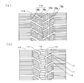
- the tread pattern which has the rib-shaped land part 18 in the tire width direction center may be sufficient.
- the sipe 19 formed on the tire tread surface side of the rib-like land portion 18 is a linear or wave sipe extending in a direction parallel to the tire width direction.
- Example 10 The tire (the product of the present invention) in which a sipe having a first inclined portion located on the inner side in the tire width direction and a second inclined portion located on the outer side in the tire width direction is formed on the inner block shown in FIG.
- a sipe having a first inclined portion located on the inner side in the tire width direction and a second inclined portion located on the outer side in the tire width direction is formed on the inner block shown in FIG.
- the evaluation results are shown in Table 1 below. For reference, the results of examining the rigidity in the tire circumferential direction and the width direction of the block are also shown.
- the size of the inclined lug groove angle of the inclined lug groove of each tire is 30 °
- the size of the inner sipe angle of the first sipe 16 of the present invention is 30 °
- the size of the inclination angle of the outer sipe is 0.
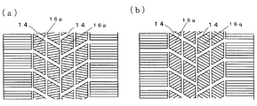
- the size of the sipe angle of the sipe 16p of the conventional product 1 is 10 °
- the size of the sipe angle of the sipe 16q of the conventional product 2 is 30 °.
- the tire size of each tire is 205 / 55R16, and the internal pressure is 220 kPa.
- the traction performance on snow was evaluated by measuring the time (acceleration time) required for the test vehicle to travel 50 m from a stationary state with the accelerator fully open, and the reciprocal of this acceleration time was evaluated by an index with the conventional product 1 as 100.
- the handling performance on snow was evaluated by an index with the conventional product 1 as 100, which is the feeling when the driver runs on a snowy road test course. The higher the number, the better the snow handling performance.
- the edge component in the lateral direction is increased, so that the handling performance on snow is improved, but the tire width of the block compared to the conventional product 1 is improved. It was found that the directional rigidity was reduced.
- the tire of the present invention can enhance both the front and rear edge effect and the lateral edge effect while ensuring the tire circumferential rigidity and the width direction rigidity equivalent to those of the conventional product 1, so that the traction performance on snow is improved. It has been confirmed that it is possible to improve both snow handling performance and snow handling performance.
Landscapes
- Engineering & Computer Science (AREA)
- Mechanical Engineering (AREA)
- Tires In General (AREA)
Abstract
雪上トラクション性能と雪上ハンドリング性能とをともに向上させることができるタイヤを提供するために、タイヤ10のトレッド11表面にタイヤ周方向に沿って延長するように形成された2本の周方向溝12aと周方向溝12aと交差する方向に延長する2本のラグ溝13aとにより区画される内側ブロック14に、内側ブロック14のタイヤ幅方向内側に設けられた第1の傾斜部16aと、タイヤ幅方向外側に設けられた第2の傾斜部16bとを備えたサイプ16を形成するとともに、第2の傾斜部16bの延長方向とタイヤ幅方向に平行な方向とのなす角度を、第1の傾斜部16aの延長方向とタイヤ幅方向に平行な方向とのなす角度よりも小さくした。
Description
本発明は、ブロックのタイヤ踏面側にサイプが形成されたタイヤに関するもので、特に、雪上走行性能を向上させたタイヤに関する。
従来、スタッドレスタイヤのトレッドパターンとして、雪上走行性能を向上させるため、周方向溝に交差する方向に延長するラグ溝を設けるとともに、周方向溝とラグ溝とにより区画されたブロックの表面にサイプを形成したものが多く用いられている(例えば、特許文献1参照)。
特許文献1では、ラグ溝のタイヤ幅方向に対する傾斜角度を、±5°~±45°の範囲とするとともに、タイヤ幅方向に平行な方向に延長するサイプを形成することで、雪上でのブレーキ及びトラクション性能を低下させることなく、雪上での耐横滑り性能を向上させることができるとしている。
特許文献1では、ラグ溝のタイヤ幅方向に対する傾斜角度を、±5°~±45°の範囲とするとともに、タイヤ幅方向に平行な方向に延長するサイプを形成することで、雪上でのブレーキ及びトラクション性能を低下させることなく、雪上での耐横滑り性能を向上させることができるとしている。
しかしながら、上記特許文献1のタイヤでは、サイプの延長方向がタイヤ幅方向に平行な方向であるため、雪上トラクション性能には優れるが、雪上ハンドリング性能が十分ではなかった。
すなわち、サイプの傾斜角度が大きいと雪上ハンドリング性能には優れるが、雪上トラクション性能が十分でなく、逆に、サイプの傾斜角度が小さいと、雪上トラクション性能には優れるが、十分な雪上ハンドリング性能を発揮できないといった問題点があった。
すなわち、サイプの傾斜角度が大きいと雪上ハンドリング性能には優れるが、雪上トラクション性能が十分でなく、逆に、サイプの傾斜角度が小さいと、雪上トラクション性能には優れるが、十分な雪上ハンドリング性能を発揮できないといった問題点があった。
本発明は、従来の問題点に鑑みてなされたもので、雪上トラクション性能と雪上ハンドリング性能とをともに向上させることができるタイヤを提供することを目的とする。
本発明は、トレッド表面にタイヤ周方向に沿って延長するように形成された周方向溝と、前記周方向溝と交差する方向に延長するラグ溝と、前記周方向溝と前記ラグ溝とにより区画される複数のブロックとを備えたタイヤであって、前記複数のブロックのうち、周方向溝とラグ溝とにより区画されたブロックには、前記ブロックのタイヤ幅方向内側に設けられて、一端が前記周方向溝または前記ラグ溝に開口し、他端が当該ブロック内部で終端する第1の傾斜部と、タイヤ幅方向外側に設けられて、前記第1の傾斜部の終端から前記第1の傾斜部の始端側とは逆方向に延長する第2の傾斜部とを備えたサイプが形成され、前記第2の傾斜部の延長方向とタイヤ幅方向に平行な方向とのなす角度(サイプ傾斜角)が、前記第1の傾斜部のサイプ傾斜角よりも小さいことを特徴とする。
このように、サイプのタイヤ幅方向内側の傾斜角を大きくすることでブロック剛性を確保しつつ前後及び横エッジ効果を発揮させるとともに、サイプのタイヤ幅方向内側の傾斜角を小さくして横入力に対するブロックエッジ圧を高めるようにしたので、雪上トラクション性能と雪上ハンドリング性能とをともに向上させることができる。
このように、サイプのタイヤ幅方向内側の傾斜角を大きくすることでブロック剛性を確保しつつ前後及び横エッジ効果を発揮させるとともに、サイプのタイヤ幅方向内側の傾斜角を小さくして横入力に対するブロックエッジ圧を高めるようにしたので、雪上トラクション性能と雪上ハンドリング性能とをともに向上させることができる。
なお、前記発明の概要は、本発明の必要な全ての特徴を列挙したものではなく、これらの特徴群のサブコンビネーションもまた、発明となり得る。
以下、本発明の実施の形態について、図面に基づき説明する。
図1は本実施の形態に係るタイヤ10のトレッドパターンの一例を示す図で、同図の上下方向がタイヤ周方向、左右方向がタイヤ幅方向である。
同図において、11はトレッド、12a,12bはトレッド11の踏面側にタイヤ周方向に沿って延長するように形成された周方向溝、13a,13bは周方向溝12a,12bに交差する方向に沿って延長するラグ溝である。
以下、周方向溝のうち、タイヤ幅方向内側に位置する周方向溝を内側主溝12a、タイヤ幅方向外側に位置する周方向溝をショルダー溝12b、ショルダー溝12bからタイヤ幅方向内側に向かって延長するラグ溝を傾斜ラグ溝13a、ショルダー溝12bからタイヤ幅方向外側に向かって延長するラグ溝をショルダーラグ溝13bという。
また、符号14は、内側主溝12aと傾斜ラグ溝13aとにより区画された内側ブロック、15は、ショルダー溝12bとショルダーラグ溝13bとにより区画されたショルダーブロックで、内側ブロック14のタイヤ踏面側には第1のサイプ16が形成され、ショルダーブロック15のタイヤ踏面側には第2のサイプ17が形成されている。
傾斜ラグ溝13aは、タイヤ周方向とタイヤ幅方向の両方に対して傾斜している。詳細には、センターラインCLよりも右側に位置する傾斜ラグ溝13aは、タイヤ幅方向中央に位置する内側主溝12aからタイヤ幅方向右側に位置するショルダーラグ溝13bまで連続して右上がりに延長し、CLよりも左側に位置する傾斜ラグ溝13aはタイヤ幅方向中央に位置する内側主溝12aからタイヤ幅方向左側に位置するショルダーラグ溝13bまで連続して右下がりに延長している。
図2(a)に示すように、右側の傾斜ラグ溝13aと同図のy軸方向で示すタイヤ幅方向とのなす角度(以下、傾斜ラグ溝角という)θとする。なお、傾斜ラグ溝角θはy軸から反時計回りに測った角度を(+)とした。本例では、右側の傾斜ラグ溝13aの傾斜ラグ溝角を30°、左側の傾斜ラグ溝13aの傾斜ラグ溝角を-30°とした。
一方、ショルダーラグ溝13bは、ショルダー溝12bからタイヤ幅方向外側に向かって、タイヤ幅方向に平行な方向に延長し、タイヤ踏面の外側に開口している。ショルダーラグ溝13bのラグ溝角は0°である。
図2(a)に示すように、右側の傾斜ラグ溝13aと同図のy軸方向で示すタイヤ幅方向とのなす角度(以下、傾斜ラグ溝角という)θとする。なお、傾斜ラグ溝角θはy軸から反時計回りに測った角度を(+)とした。本例では、右側の傾斜ラグ溝13aの傾斜ラグ溝角を30°、左側の傾斜ラグ溝13aの傾斜ラグ溝角を-30°とした。
一方、ショルダーラグ溝13bは、ショルダー溝12bからタイヤ幅方向外側に向かって、タイヤ幅方向に平行な方向に延長し、タイヤ踏面の外側に開口している。ショルダーラグ溝13bのラグ溝角は0°である。
第1のサイプ16は、タイヤ幅方向内側に位置する第1の傾斜部16aとタイヤ幅方向外側に位置する第2の傾斜部16bとを有する、平面視折れ線状のサイプである。第1の傾斜部16aは、一端が内側主溝12aまたは傾斜ラグ溝13aに開口し、他端が内側ブロック14内で終端している。また、第2の傾斜部16bは、第1の傾斜部16aの終端を始端として、第1の傾斜部16aとは逆方向(第1の傾斜部16aが右方向なら左方向)に延長し、他端が傾斜ラグ溝13aまたはショルダー溝12bに開口する。
一方、第2のサイプ17は、タイヤ幅方向に平行な方向に延長するサイプで、サイプ角は0°である。
一方、第2のサイプ17は、タイヤ幅方向に平行な方向に延長するサイプで、サイプ角は0°である。
以下、第1のサイプ16について、図2(a)を参照して詳細に説明する。
第1のサイプ16の第1の傾斜部16aは、第1のサイプ16が形成された内側ブロック14を区画する傾斜ラグ溝13aとは逆方向に傾斜している。すなわち、右側の内側ブロック14に設けられた第1のサイプ16では、第1の傾斜部16aの傾斜が右下がりであり、左側の内側ブロック14に設けられた第1のサイプ16では左下がりである。第1の傾斜部16aの延長方向とタイヤ幅方向に平行な方向とのなす角度(以下、内側サイプ角という)αの大きさはとしては、-15°~-45°の範囲とすることが好ましい。
一方、第2の傾斜部16bの延長方向はタイヤ幅方向に平行である。すなわち、第2の傾斜部16bの延長方向とタイヤ幅方向に平行な方向とのなす角度(以下、外側サイプ角という)βは0°である。したがって、第1のサイプ16のうちの、第2の傾斜部16bがショルダー溝12bに開口している第1のサイプ16は、第2の傾斜部16bにおいて、ショルダー溝12bと直交している。
一般に、スリップ角が付与された状態での雪上におけるハンドリング走行においては、サイプ角が大きい方が、横方向のエッジ成分が増加するので好ましい。また、ハンドリング性能に対する寄与はブロックのタイヤ幅方向内側の方が大きい。本例では、上記のように、第1のサイプ16は、タイヤ幅方向内側でタイヤ周方向に対して大きく傾いているので、内側ブロック14の周方向の剛性を確保することができるとともに、前後エッジ効果と横エッジ効果とをともに高めることができる。
一方、雪上トラクション性能を向上させるには、サイプ角を0°、すなわち、サイプの延長方向がタイヤ幅方向と平行である方が、前後方向のエッジ成分が増加するので好ましい。また、横入力に対する影響は、ブロックのタイヤ幅方向外の方が大きい。本例では、上記のように、第1のサイプ16は、外側サイプ角βが0°なので、内側ブロック14の横方向の剛性を高めることができるとともに、トラクションのエッジ効果(前後エッジ効果)を高めることができる。
すなわち、内側ブロック14の踏面側に形成される第1のサイプ16を、タイヤ幅方向内側に位置し、傾斜ラグ溝13aとは反対方向に傾斜する第1の傾斜部16aと、タイヤ幅方向外側に位置し、タイヤ幅方向に平行な方向に延長する第2の傾斜部16bとから構成することで、雪上トラクション性能と雪上ハンドリング性能とをともに向上させることができる。
また、第1の傾斜部16aを傾斜ラグ溝13aとは反対方向に傾斜させて、内側ブロック14の斜め方向(特に、傾斜ラグ溝13aにほぼ直交する方向)からの入力に対する剛性を高めるようにしたので、雪上トラクション性能と雪上ハンドリング性能とを更に向上させることができる。
また、第2の傾斜部の延長方向をタイヤ幅方向に平行とすることで、横入力に対するブロックエッジ圧を更に高めるようにしたので、雪上ハンドリング性能を更に向上させることができる。
また、ラグ溝を、タイヤ周方向とタイヤ幅方向の両方に対して傾斜させ、かつ、前記サイプの第1の傾斜部を、前記ラグ溝の傾斜方向とは逆方向(ラグ溝が右上がりなら、右下がり)に傾斜させたので、斜め方向からの入力に対する剛性を高めることができ、雪上トラクション性能と雪上ハンドリング性能とを更に向上させることができる。
また、ラグ溝を、タイヤ周方向とタイヤ幅方向の両方に対して傾斜させ、かつ、前記サイプの第1の傾斜部を、前記ラグ溝の傾斜方向とは逆方向(ラグ溝が右上がりなら、右下がり)に傾斜させたので、斜め方向からの入力に対する剛性を高めることができ、雪上トラクション性能と雪上ハンドリング性能とを更に向上させることができる。
以上、本発明を実施の形態を用いて説明したが、本発明の技術的範囲は前記実施の形態に記載の範囲には限定されない。前記実施の形態に、多様な変更または改良を加えることが可能であることが当業者にも明らかである。そのような変更または改良を加えた形態も本発明の技術的範囲に含まれ得ることが、特許請求の範囲から明らかである。
例えば、前記実施の形態では、第1のサイプ16を折れ線状としたが、波状のサイプであってもよい。また、第2のサイプ17についても、波状としてもよい。
また、前記実施の形態では、第1のサイプ16の外側サイプ角βを0°としたが、図2(b)に示すように、傾斜ラグ溝13aとは反対方向に傾斜していてもよい。但し、この場合にも、外側サイプ角βの大きさを内側サイプ角αの大きさよりも小さくすることが、雪上トラクション性能を確保する上で好ましい。
また、前記実施の形態では、傾斜ラグ溝角θの大きさを30°としたが、これに限るものではなく、15°~45°の範囲であれば、雪上トラクション性能と雪上ハンドリング性能とを確保することができる。
また、前記実施の形態では、第1の傾斜部16aの終端を、内側ブロック14の対角線上に位置させたが、これに限るものではなく、例えば、第1の傾斜部16aの終端を内側ブロック14の対角線上にある2つの頂点を結ぶ曲線上に位置させるなど、内側ブロック14の形状により適宜決定すればよい。また、第1のサイプ16は全て折れ線状とする必要はなく、内側ブロック14のタイヤ周方向中央部を折れ線状とし、端部については、第1の傾斜部16aもしくは第2の傾斜部16bのみとしてもよい。
また、前記実施の形態では、第1の傾斜部16aの傾斜を傾斜ラグ溝13aとは反対方向としたが、図3(a)に示すように、傾斜ラグ溝13aと同一方向としてもよい。この場合、前記実施の形態に比較して、内側ブロック14の斜め方向からの入力に対する剛性は低くなるが、第1の傾斜部16aにより前後エッジ効果と横エッジ効果とをともに高めることができるとともに、第2の傾斜部16bにより横方向の剛性を高めるので、雪上トラクション性能と雪上ハンドリング性能とをともに向上させることができる。
また、前記実施の形態では、トレッドパターンをブロックパターンとしたが、図3(b)に示すように、タイヤ幅方向中心にリブ状陸部18を有するトレッドパターンであってもよい。この場合、リブ状陸部18のタイヤ踏面側に形成するサイプ19としては、タイヤ幅方向に平行な方向に延長する直線状もしくは波状のサイプとすることが好ましい。
また、前記実施の形態では、トレッドパターンをブロックパターンとしたが、図3(b)に示すように、タイヤ幅方向中心にリブ状陸部18を有するトレッドパターンであってもよい。この場合、リブ状陸部18のタイヤ踏面側に形成するサイプ19としては、タイヤ幅方向に平行な方向に延長する直線状もしくは波状のサイプとすることが好ましい。
[実施例]
図1に示した、内側ブロックにタイヤ幅方向内側に位置する第1の傾斜部とタイヤ幅方向外側に位置する第2の傾斜部とを有するサイプが形成されたタイヤ(本発明品)と、図4に示す、全てのサイプが傾斜している従来のタイヤ(従来品1,2)を準備し、各タイヤを試験車両に搭載して走行試験を行い、雪上トラクション性能と雪上ハンドリング性能とを評価した結果を以下の表1に示す。なお、参考のため、ブロックのタイヤ周方向剛性及び幅方向についても調べた結果についても併せて記した。
なお、各タイヤの傾斜ラグ溝の傾斜ラグ溝角の大きさは30°、本発明品の第1のサイプ16の内側サイプ角の大きさは30°、外側サイプの傾斜角の大きさは0°、従来品1のサイプ16pのサイプ角の大きさは10°、従来品2のサイプ16qのサイプ角の大きさは30°である。
また、各タイヤのタイヤサイズは205/55R16であり、内圧は220kPaである。
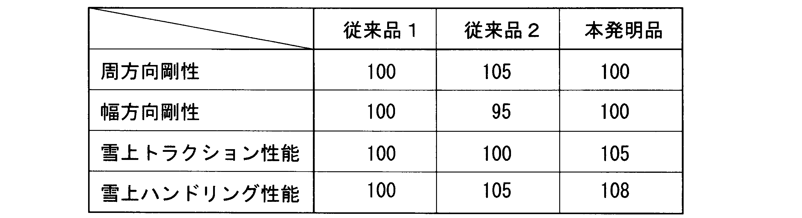
雪上トラクション性能は、試験車両を静止状態からアクセルを全開にして50m走行するまでに要する時間(加速タイム)を測定し、この加速タイムの逆数を、従来品1を100とした指数で評価した。数字が高い程加速タイムが短く、雪上トラクション性能が高い。
雪上ハンドリング性能は、ドライバーが雪路のテストコースを走行させたときのフィーリングを、従来品1を100とした指数で評価した。数字が高い程、雪上ハンドリング性能が高い。
図1に示した、内側ブロックにタイヤ幅方向内側に位置する第1の傾斜部とタイヤ幅方向外側に位置する第2の傾斜部とを有するサイプが形成されたタイヤ(本発明品)と、図4に示す、全てのサイプが傾斜している従来のタイヤ(従来品1,2)を準備し、各タイヤを試験車両に搭載して走行試験を行い、雪上トラクション性能と雪上ハンドリング性能とを評価した結果を以下の表1に示す。なお、参考のため、ブロックのタイヤ周方向剛性及び幅方向についても調べた結果についても併せて記した。
なお、各タイヤの傾斜ラグ溝の傾斜ラグ溝角の大きさは30°、本発明品の第1のサイプ16の内側サイプ角の大きさは30°、外側サイプの傾斜角の大きさは0°、従来品1のサイプ16pのサイプ角の大きさは10°、従来品2のサイプ16qのサイプ角の大きさは30°である。
また、各タイヤのタイヤサイズは205/55R16であり、内圧は220kPaである。
雪上ハンドリング性能は、ドライバーが雪路のテストコースを走行させたときのフィーリングを、従来品1を100とした指数で評価した。数字が高い程、雪上ハンドリング性能が高い。
表1に示すように、単にサイプ角を大きくした従来品2のタイヤでは、横方向のエッジ成分が増加するので、雪上ハンドリング性能は向上するものの、従来品1に比較して、ブロックのタイヤ幅方向剛性が低下してしまうことがわかった。
これに対して、本発明のタイヤは、従来品1と同等のタイヤ周方向剛性と幅方向剛性とを確保しつつ、前後エッジ効果と横エッジ効果とをともに高めることができるので、雪上トラクション性能と雪上ハンドリング性能とをともに向上させることができることが確認された。
これに対して、本発明のタイヤは、従来品1と同等のタイヤ周方向剛性と幅方向剛性とを確保しつつ、前後エッジ効果と横エッジ効果とをともに高めることができるので、雪上トラクション性能と雪上ハンドリング性能とをともに向上させることができることが確認された。
10 タイヤ、11 トレッド、
12a 内側主溝、12b ショルダー溝、
13a 傾斜ラグ溝、13b ショルダーラグ溝、14 内側ブロック、
15 ショルダーブロック、16 第1のサイプ、16a 第1の傾斜部、
16b 第2の傾斜部、17 第2のサイプ。
12a 内側主溝、12b ショルダー溝、
13a 傾斜ラグ溝、13b ショルダーラグ溝、14 内側ブロック、
15 ショルダーブロック、16 第1のサイプ、16a 第1の傾斜部、
16b 第2の傾斜部、17 第2のサイプ。
Claims (3)
- トレッド表面にタイヤ周方向に沿って延長するように形成された周方向溝と、前記周方向溝と交差する方向に延長するラグ溝と、前記周方向溝と前記ラグ溝とにより区画される複数のブロックとを備えたタイヤであって、
前記複数のブロックのうち、周方向溝とラグ溝とにより区画されたブロックには、
前記ブロックのタイヤ幅方向内側に設けられて、一端が前記周方向溝または前記ラグ溝に開口し、他端が当該ブロック内部で終端する第1の傾斜部と、タイヤ幅方向外側に設けられて、前記第1の傾斜部の終端から前記第1の傾斜部の始端側とは逆方向に延長する第2の傾斜部とを備えたサイプが形成され、
前記第2の傾斜部の延長方向とタイヤ幅方向に平行な方向とのなす角度が、前記第1の傾斜部の延長方向とタイヤ幅方向に平行な方向とのなす角度よりも小さいことを特徴とするタイヤ。 - 前記第2の傾斜部の延長方向がタイヤ幅方向に平行であることを特徴とする請求項1に記載のタイヤ。
- 前記ラグ溝が、タイヤ周方向とタイヤ幅方向の両方に対して傾斜しており、前記サイプの第1の傾斜部は、前記ラグ溝の傾斜方向とは逆方向に傾斜していることを特徴とする請求項1または請求項2に記載のタイヤ。
Applications Claiming Priority (2)
| Application Number | Priority Date | Filing Date | Title |
|---|---|---|---|
| JP2014084555A JP2015202836A (ja) | 2014-04-16 | 2014-04-16 | タイヤ |
| JP2014-084555 | 2014-04-16 |
Publications (1)
| Publication Number | Publication Date |
|---|---|
| WO2015159796A1 true WO2015159796A1 (ja) | 2015-10-22 |
Family
ID=54324005
Family Applications (1)
| Application Number | Title | Priority Date | Filing Date |
|---|---|---|---|
| PCT/JP2015/061118 Ceased WO2015159796A1 (ja) | 2014-04-16 | 2015-04-09 | タイヤ |
Country Status (2)
| Country | Link |
|---|---|
| JP (1) | JP2015202836A (ja) |
| WO (1) | WO2015159796A1 (ja) |
Families Citing this family (1)
| Publication number | Priority date | Publication date | Assignee | Title |
|---|---|---|---|---|
| JP7394613B2 (ja) * | 2019-12-13 | 2023-12-08 | Toyo Tire株式会社 | 空気入りタイヤ |
Citations (3)
| Publication number | Priority date | Publication date | Assignee | Title |
|---|---|---|---|---|
| JPS62292508A (ja) * | 1986-06-12 | 1987-12-19 | Yokohama Rubber Co Ltd:The | 雪氷路用タイヤ |
| JPH0310913A (ja) * | 1989-06-08 | 1991-01-18 | Yokohama Rubber Co Ltd:The | 空気入りタイヤ |
| JPH04266505A (ja) * | 1990-11-14 | 1992-09-22 | Goodyear Tire & Rubber Co:The | 冬期型タイヤトレッド |
-
2014
- 2014-04-16 JP JP2014084555A patent/JP2015202836A/ja active Pending
-
2015
- 2015-04-09 WO PCT/JP2015/061118 patent/WO2015159796A1/ja not_active Ceased
Patent Citations (3)
| Publication number | Priority date | Publication date | Assignee | Title |
|---|---|---|---|---|
| JPS62292508A (ja) * | 1986-06-12 | 1987-12-19 | Yokohama Rubber Co Ltd:The | 雪氷路用タイヤ |
| JPH0310913A (ja) * | 1989-06-08 | 1991-01-18 | Yokohama Rubber Co Ltd:The | 空気入りタイヤ |
| JPH04266505A (ja) * | 1990-11-14 | 1992-09-22 | Goodyear Tire & Rubber Co:The | 冬期型タイヤトレッド |
Also Published As
| Publication number | Publication date |
|---|---|
| JP2015202836A (ja) | 2015-11-16 |
Similar Documents
| Publication | Publication Date | Title |
|---|---|---|
| US9481211B2 (en) | Pneumatic tire | |
| JP6126879B2 (ja) | 空気入りタイヤ | |
| JP5102711B2 (ja) | 空気入りタイヤ | |
| JP6278843B2 (ja) | タイヤ | |
| CN102007006B (zh) | 充气轮胎 | |
| JP5690339B2 (ja) | タイヤ | |
| WO2015186443A1 (ja) | 空気入りタイヤ | |
| WO2015030101A1 (ja) | 空気入りタイヤ | |
| JP6287554B2 (ja) | 空気入りタイヤ | |
| WO2011087134A1 (ja) | 空気入りタイヤ | |
| JP6686439B2 (ja) | 空気入りタイヤ | |
| JP5862837B2 (ja) | オールシーズンタイヤ | |
| WO2014054225A1 (ja) | 空気入りタイヤ | |
| US10576791B2 (en) | Tire | |
| JP2014080112A (ja) | 空気入りタイヤ | |
| JP2016107918A (ja) | 重荷重用空気入りタイヤ | |
| US10232669B2 (en) | Heavy duty pneumatic tire | |
| JP2015131642A (ja) | 空気入りタイヤ | |
| JP5624329B2 (ja) | 空気入りタイヤ | |
| JP2012066797A (ja) | 空気入りタイヤ | |
| WO2014207981A1 (ja) | 空気入りタイヤ | |
| JP2015202836A (ja) | タイヤ | |
| JP6030422B2 (ja) | 空気入りタイヤ | |
| JP5873538B2 (ja) | 空気入りタイヤ | |
| JP2020100192A (ja) | 空気入りタイヤ |
Legal Events
| Date | Code | Title | Description |
|---|---|---|---|
| 121 | Ep: the epo has been informed by wipo that ep was designated in this application |
Ref document number: 15780087 Country of ref document: EP Kind code of ref document: A1 |
|
| NENP | Non-entry into the national phase |
Ref country code: DE |
|
| 122 | Ep: pct application non-entry in european phase |
Ref document number: 15780087 Country of ref document: EP Kind code of ref document: A1 |