WO2015159343A1 - 延伸積層体の製造方法 - Google Patents
延伸積層体の製造方法 Download PDFInfo
- Publication number
- WO2015159343A1 WO2015159343A1 PCT/JP2014/060615 JP2014060615W WO2015159343A1 WO 2015159343 A1 WO2015159343 A1 WO 2015159343A1 JP 2014060615 W JP2014060615 W JP 2014060615W WO 2015159343 A1 WO2015159343 A1 WO 2015159343A1
- Authority
- WO
- WIPO (PCT)
- Prior art keywords
- laminate
- stretching
- stretched
- polarizing film
- roll
- Prior art date
- Legal status (The legal status is an assumption and is not a legal conclusion. Google has not performed a legal analysis and makes no representation as to the accuracy of the status listed.)
- Ceased
Links
Images


Classifications
-
- B—PERFORMING OPERATIONS; TRANSPORTING
- B32—LAYERED PRODUCTS
- B32B—LAYERED PRODUCTS, i.e. PRODUCTS BUILT-UP OF STRATA OF FLAT OR NON-FLAT, e.g. CELLULAR OR HONEYCOMB, FORM
- B32B37/00—Methods or apparatus for laminating, e.g. by curing or by ultrasonic bonding
- B32B37/06—Methods or apparatus for laminating, e.g. by curing or by ultrasonic bonding characterised by the heating method
-
- B—PERFORMING OPERATIONS; TRANSPORTING
- B32—LAYERED PRODUCTS
- B32B—LAYERED PRODUCTS, i.e. PRODUCTS BUILT-UP OF STRATA OF FLAT OR NON-FLAT, e.g. CELLULAR OR HONEYCOMB, FORM
- B32B27/00—Layered products comprising a layer of synthetic resin
- B32B27/06—Layered products comprising a layer of synthetic resin as the main or only constituent of a layer, which is next to another layer of the same or of a different material
- B32B27/08—Layered products comprising a layer of synthetic resin as the main or only constituent of a layer, which is next to another layer of the same or of a different material of synthetic resin
-
- B—PERFORMING OPERATIONS; TRANSPORTING
- B32—LAYERED PRODUCTS
- B32B—LAYERED PRODUCTS, i.e. PRODUCTS BUILT-UP OF STRATA OF FLAT OR NON-FLAT, e.g. CELLULAR OR HONEYCOMB, FORM
- B32B27/00—Layered products comprising a layer of synthetic resin
- B32B27/30—Layered products comprising a layer of synthetic resin comprising vinyl (co)polymers; comprising acrylic (co)polymers
- B32B27/306—Layered products comprising a layer of synthetic resin comprising vinyl (co)polymers; comprising acrylic (co)polymers comprising vinyl acetate or vinyl alcohol (co)polymers
-
- B—PERFORMING OPERATIONS; TRANSPORTING
- B32—LAYERED PRODUCTS
- B32B—LAYERED PRODUCTS, i.e. PRODUCTS BUILT-UP OF STRATA OF FLAT OR NON-FLAT, e.g. CELLULAR OR HONEYCOMB, FORM
- B32B27/00—Layered products comprising a layer of synthetic resin
- B32B27/36—Layered products comprising a layer of synthetic resin comprising polyesters
-
- B—PERFORMING OPERATIONS; TRANSPORTING
- B32—LAYERED PRODUCTS
- B32B—LAYERED PRODUCTS, i.e. PRODUCTS BUILT-UP OF STRATA OF FLAT OR NON-FLAT, e.g. CELLULAR OR HONEYCOMB, FORM
- B32B37/00—Methods or apparatus for laminating, e.g. by curing or by ultrasonic bonding
- B32B37/0046—Methods or apparatus for laminating, e.g. by curing or by ultrasonic bonding characterised by constructional aspects of the apparatus
- B32B37/0053—Constructional details of laminating machines comprising rollers; Constructional features of the rollers
-
- G—PHYSICS
- G02—OPTICS
- G02B—OPTICAL ELEMENTS, SYSTEMS OR APPARATUS
- G02B5/00—Optical elements other than lenses
- G02B5/30—Polarising elements
-
- G—PHYSICS
- G02—OPTICS
- G02F—OPTICAL DEVICES OR ARRANGEMENTS FOR THE CONTROL OF LIGHT BY MODIFICATION OF THE OPTICAL PROPERTIES OF THE MEDIA OF THE ELEMENTS INVOLVED THEREIN; NON-LINEAR OPTICS; FREQUENCY-CHANGING OF LIGHT; OPTICAL LOGIC ELEMENTS; OPTICAL ANALOGUE/DIGITAL CONVERTERS
- G02F1/00—Devices or arrangements for the control of the intensity, colour, phase, polarisation or direction of light arriving from an independent light source, e.g. switching, gating or modulating; Non-linear optics
- G02F1/01—Devices or arrangements for the control of the intensity, colour, phase, polarisation or direction of light arriving from an independent light source, e.g. switching, gating or modulating; Non-linear optics for the control of the intensity, phase, polarisation or colour
- G02F1/13—Devices or arrangements for the control of the intensity, colour, phase, polarisation or direction of light arriving from an independent light source, e.g. switching, gating or modulating; Non-linear optics for the control of the intensity, phase, polarisation or colour based on liquid crystals, e.g. single liquid crystal display cells
- G02F1/133—Constructional arrangements; Operation of liquid crystal cells; Circuit arrangements
- G02F1/1333—Constructional arrangements; Manufacturing methods
- G02F1/1335—Structural association of cells with optical devices, e.g. polarisers or reflectors
-
- B—PERFORMING OPERATIONS; TRANSPORTING
- B32—LAYERED PRODUCTS
- B32B—LAYERED PRODUCTS, i.e. PRODUCTS BUILT-UP OF STRATA OF FLAT OR NON-FLAT, e.g. CELLULAR OR HONEYCOMB, FORM
- B32B38/00—Ancillary operations in connection with laminating processes
- B32B38/0012—Mechanical treatment, e.g. roughening, deforming, stretching
- B32B2038/0028—Stretching, elongating
-
- B—PERFORMING OPERATIONS; TRANSPORTING
- B32—LAYERED PRODUCTS
- B32B—LAYERED PRODUCTS, i.e. PRODUCTS BUILT-UP OF STRATA OF FLAT OR NON-FLAT, e.g. CELLULAR OR HONEYCOMB, FORM
- B32B2457/00—Electrical equipment
- B32B2457/20—Displays, e.g. liquid crystal displays, plasma displays
- B32B2457/202—LCD, i.e. liquid crystal displays
Definitions
- the present invention relates to a method for producing a stretched laminate.
- a liquid crystal display device which is a typical image display device, has polarizing films disposed on both sides of a liquid crystal cell due to the image forming method.
- a thin polarizing film for example, a laminate of a specific thermoplastic resin substrate and a polyvinyl alcohol-based resin layer is stretched in the air and further stretched in a boric acid aqueous solution.
- a method for obtaining a polarizing film has been proposed (for example, Patent Document 1). According to such a method, the laminate can be stretched at a high magnification, and a polarizing film having excellent optical properties can be obtained.
- a polarizing film when manufacturing a polarizing film, it is generally known that the film contracts in a direction substantially perpendicular to the stretching direction by stretching, and it is known that optical characteristics can be improved by contracting.
- the shrinkage rate is too high, a polarizing film having a desired size (product width) cannot be obtained, and for example, there is a problem that it cannot sufficiently cope with high-speed production.
- the present invention has been made to solve the above-described conventional problems, and its main purpose is to provide a stretched laminate that can achieve high productivity while ensuring the optical properties of the obtained polarizing film. To do.
- the method for producing a stretched laminate of the present invention includes a step of forming a polyvinyl alcohol-based resin layer on a long polyester resin substrate to produce a laminate, while conveying the laminate in the longitudinal direction, A step of stretching in the air at 100 ° C. or less due to a difference in peripheral speed between rolls, and a step of heating the stretched laminate to 110 ° C. or more.
- an inter-stretching distance L 1 and the laminate Satisfies the relationship of L 1 /W ⁇ 0.3.
- the draw ratio of the said air drawing is 1.4 times or more.
- the laminate is stretched in the longitudinal direction in the heating step. This stretching is preferably substantially fixed end uniaxial stretching.
- the film in the heating step, while conveying the laminate in the longitudinal direction was stretched by the peripheral speed difference between rolls, and the stretching distance L 2, the width W of the stretched immediately before the stack ' Satisfies the relationship of L / W ′ ⁇ 0.12.
- the film is stretched by 1.7 times to 2.3 times.
- a stretched laminate is provided. This stretched laminate is produced by the above production method.
- the manufacturing method of a polarizing film is provided. In this method of manufacturing a polarizing film, the stretched laminate is used. In a preferred embodiment, the stretched laminate is stretched in an aqueous boric acid solution.
- a laminate obtained by forming a polyvinyl alcohol-based resin layer on a long polyester-based resin substrate is subjected to free end stretching at 100 ° C. or lower and then heated at 110 ° C. or higher.
- a polarizing film that achieves high productivity and has excellent optical properties can be produced.
- stretching laminated body of this invention is a process which forms a polyvinyl alcohol-type resin layer on an elongate polyester-type resin base material, produces a laminated body, and conveys this laminated body to a longitudinal direction. However, it includes a step of stretching in the air at 100 ° C. or less due to a difference in peripheral speed between the rolls, and a step of heating the stretched laminate to 110 ° C. or more.
- each process will be described.
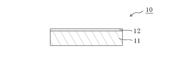
- FIG. 1 is a partial cross-sectional view of a laminate according to a preferred embodiment of the present invention.
- the laminate 10 includes a polyester resin base material 11 and a polyvinyl alcohol resin layer 12.
- the laminate 10 is produced by forming a polyvinyl alcohol-based resin layer 12 on a long polyester-based resin substrate. Any appropriate method can be adopted as a method of forming the polyvinyl alcohol-based resin layer 12.
- the PVA resin layer 12 is formed by applying a coating liquid containing a polyvinyl alcohol resin (hereinafter referred to as “PVA resin”) on the polyester resin substrate 11 and drying it.
- PVA resin a coating liquid containing a polyvinyl alcohol resin
- the thickness of the polyester resin substrate before stretching is preferably 20 ⁇ m to 300 ⁇ m, more preferably 50 ⁇ m to 200 ⁇ m. If it is less than 20 ⁇ m, it may be difficult to form a PVA-based resin layer. If it exceeds 300 ⁇ m, an excessive load may be required for stretching.
- an amorphous (non-crystallized) polyethylene terephthalate resin is preferably used as a material for forming the polyester resin base material.
- amorphous (hard to crystallize) polyethylene terephthalate resin is particularly preferably used.
- Specific examples of the amorphous polyethylene terephthalate resin include a copolymer further containing isophthalic acid as a dicarboxylic acid, and a copolymer further containing cyclohexanedimethanol as a glycol.
- the glass transition temperature (Tg) of the polyester resin base material is preferably 170 ° C. or lower, more preferably 120 ° C. or lower, and further preferably 80 ° C. or lower.
- the glass transition temperature of the polyester resin substrate is preferably 60 ° C. or higher.
- the glass transition temperature (Tg) is a value determined according to JIS K 7121.
- the polyester resin base material may be stretched in advance (before forming the PVA resin layer). In one embodiment, it is extended in the transverse direction of an elongated polyester resin substrate.
- the lateral direction is preferably a direction orthogonal to the extending direction of the laminate described later.
- orthogonal includes the case of being substantially orthogonal.
- substantially orthogonal includes the case of 90 ° ⁇ 5.0 °, preferably 90 ° ⁇ 3.0 °, more preferably 90 ° ⁇ 1.0 °.
- the stretching temperature of the polyester resin substrate is preferably Tg-10 ° C. to Tg + 50 ° C. with respect to the glass transition temperature (Tg).
- the draw ratio of the polyester resin substrate is preferably 1.5 to 3.0 times.
- Arbitrary appropriate methods can be employ
- any appropriate resin can be adopted as the PVA resin for forming the PVA resin layer.
- Examples thereof include polyvinyl alcohol and ethylene-vinyl alcohol copolymer.
- Polyvinyl alcohol is obtained by saponifying polyvinyl acetate.
- the ethylene-vinyl alcohol copolymer can be obtained by saponifying an ethylene-vinyl acetate copolymer.
- the degree of saponification of the PVA-based resin is usually 85 mol% to 100 mol%, preferably 95.0 mol% to 99.95 mol%, more preferably 99.0 mol% to 99.93 mol%. .
- the degree of saponification can be determined according to JIS K 6726-1994. By using a PVA-based resin having such a saponification degree, a polarizing film having excellent durability can be obtained. If the degree of saponification is too high, there is a risk of gelation.
- the average degree of polymerization of the PVA resin can be appropriately selected according to the purpose.
- the average degree of polymerization is usually 1000 to 10,000, preferably 1200 to 4500, and more preferably 1500 to 4300.
- the average degree of polymerization can be determined according to JIS K 6726-1994.
- the coating solution is typically a solution obtained by dissolving the PVA resin in a solvent.
- the solvent include water, dimethyl sulfoxide, dimethylformamide, dimethylacetamide, N-methylpyrrolidone, various glycols, polyhydric alcohols such as trimethylolpropane, and amines such as ethylenediamine and diethylenetriamine. These may be used alone or in combination of two or more. Among these, water is preferable.
- the concentration of the PVA resin in the solution is preferably 3 to 20 parts by weight with respect to 100 parts by weight of the solvent. With such a resin concentration, a uniform coating film in close contact with the polyester resin substrate can be formed.
- Additives may be added to the coating solution.
- the additive include a plasticizer and a surfactant.
- the plasticizer include polyhydric alcohols such as ethylene glycol and glycerin.
- the surfactant include nonionic surfactants. These can be used for the purpose of further improving the uniformity, dyeability and stretchability of the resulting PVA-based resin layer.
- any appropriate method can be adopted as a coating method of the coating solution. Examples thereof include a roll coating method, a spin coating method, a wire bar coating method, a dip coating method, a die coating method, a curtain coating method, a spray coating method, a knife coating method (comma coating method and the like).
- the drying temperature of the coating solution is preferably 50 ° C. or higher.
- the thickness of the PVA resin layer before stretching is preferably 3 ⁇ m to 20 ⁇ m.
- the polyester resin substrate Before forming the PVA resin layer, the polyester resin substrate may be subjected to surface treatment (for example, corona treatment), or an easy-adhesion layer may be formed on the polyester resin substrate. By performing such a treatment, the adhesion between the polyester-based resin substrate and the PVA-based resin layer can be improved.
- surface treatment for example, corona treatment
- an easy-adhesion layer may be formed on the polyester resin substrate.
- any appropriate functional layer may be formed on the side of the polyester resin substrate 11 where the PVA resin layer 12 is not formed.
- the functional layer has heat resistance. By having heat resistance, for example, even when the temperature above the glass transition temperature of the polyester resin substrate is applied to the laminate, the laminate (resin substrate) sticks to the roll used for production. It is possible to realize excellent blocking resistance.
- the functional layer is, for example, an antistatic layer containing a conductive material and a binder resin. According to such a configuration, excellent blocking resistance can be realized, and the production efficiency can be improved. Moreover, it can be excellent in antistatic property.
- any appropriate conductive material can be used as the conductive material.
- a conductive polymer is used.
- the conductive polymer include polythiophene polymer, polyacetylene polymer, polydiacetylene polymer, polyin polymer, polyphenylene polymer, polynaphthalene polymer, polyfluorene polymer, polyanthracene polymer.
- Polymer polypyrene polymer, polyazulene polymer, polypyrrole polymer, polyfuran polymer, polyselenophene polymer, polyisothianaphthene polymer, polyoxadiazole polymer, polyaniline polymer, Examples include polythiazyl polymers, polyphenylene vinylene polymers, polythienylene vinylene polymers, polyacene polymers, polyphenanthrene polymers, polyperinaphthalene polymers, and the like. These may be used alone or in combination of two or more.
- a polythiophene polymer is used.
- polythiophene polymers that can be dissolved or dispersed in an aqueous solvent are used.
- Examples of the thiophene constituting the polythiophene polymer include polyethylene dioxythiophene.
- the content of the conductive material in the antistatic layer is preferably 1 to 10% by weight, more preferably 3 to 8% by weight.
- the content of the conductive material is preferably 1 part by weight to 50 parts by weight, and more preferably 2 parts by weight to 20 parts by weight with respect to 100 parts by weight of the binder resin described later.
- any appropriate resin is used as the binder resin.
- a resin having both adhesiveness and flexibility with the resin substrate and capable of being dissolved or dispersed in an aqueous solvent is used.
- the binder resin include (meth) acrylic resin, polyurethane resin, polyester resin (for example, polylactic acid resin), phenol resin, polyvinyl alcohol resin, ethylene vinyl acetate resin, epoxy resin, silicon resin, cyano.
- An acrylic resin, a polyamide-type resin (for example, nylon) etc. are mentioned.
- a polyurethane resin is used.
- the binder resin preferably has a carboxyl group. By having a carboxyl group, an antistatic layer having excellent adhesion to the resin substrate can be obtained.
- the content of the binder resin in the antistatic layer is preferably 50% by weight to 99% by weight, more preferably 70% by weight to 95% by weight.
- the antistatic layer is typically provided by applying a resin composition containing the conductive material and the binder resin to the resin base material and drying it.
- the resin composition is preferably aqueous.
- the resin composition preferably contains a crosslinking agent.
- a crosslinking agent By crosslinking, water resistance can be imparted to the resulting antistatic layer. As a result, for example, the below-described underwater stretching can be performed satisfactorily.
- Any appropriate crosslinking agent can be adopted as the crosslinking agent.
- the crosslinking agent a polymer having a group capable of reacting with a carboxyl group is preferably used. Examples of the group that can react with a carboxyl group include an organic amino group, an oxazoline group, an epoxy group, and a carbodiimide group.
- the crosslinking agent has an oxazoline group.
- polymer examples include acrylic polymers and styrene / acrylic polymers.
- An acrylic polymer is preferable. By using an acrylic polymer, it can be stably compatible with an aqueous resin composition.
- the resin composition is preferably aqueous.
- the concentration of the binder resin in the resin composition is preferably 1.5% by weight to 15% by weight, and more preferably 2% by weight to 10% by weight.
- the content of the crosslinking agent (solid content) in the resin composition is preferably 1 to 30 parts by weight, more preferably 3 to 20 parts by weight, with respect to 100 parts by weight of the binder resin (solid content). .
- the drying temperature is preferably 50 ° C. or higher, more preferably 60 ° C. or higher.
- the drying temperature is preferably the glass transition temperature (Tg) of the resin base material + 30 ° C. or less, more preferably Tg or less.
- the thickness of the antistatic layer is preferably 0.1 ⁇ m to 10 ⁇ m, more preferably 0.2 ⁇ m to 2 ⁇ m.
- the surface resistance value of the antistatic layer is preferably less than 10 ⁇ 10 13 ⁇ / ⁇ , more preferably less than 10 ⁇ 10 11 ⁇ / ⁇ , and still more preferably less than 10 ⁇ 10 10 ⁇ / ⁇ .
- the antistatic layer is preferably stretched.
- the stretching treatment is preferably performed before the PVA resin layer is formed on the resin base material (also serves as the stretching of the polyester resin base material).
- the arithmetic average roughness Ra of the surface of the antistatic layer is preferably 10 nm or more.
- the arithmetic average roughness Ra of the antistatic layer is preferably 100 nm or less.
- the arithmetic average roughness Ra can be determined according to JIS B0601.
- the laminate is stretched by the difference in peripheral speed between rolls while being conveyed in the longitudinal direction. Specifically, tension is applied to the laminate by the peripheral speed difference between the rolls, and the film is uniaxially stretched in the longitudinal direction.
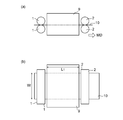
- FIG. 2 is a schematic view showing an example of an air stretching process, (a) is a view seen from the front, and (b) is a view seen from above.
- roll pairs 1 and 1 and roll pairs 2 and 2 are provided at a predetermined interval in the transport direction (MD) of the laminate, and the laminate 10 is sandwiched between the respective roll pairs. Yes.
- the roll 1 and the roll 2 rotate at different peripheral speeds, and the downstream roll 2 is set to have a higher peripheral speed than the upstream roll 1.
- any appropriate means can be adopted as the means for heating to the stretching temperature.
- an oven 9 is provided between the roll 1 and the roll 2.
- the stretching temperature is 100 ° C. or lower, preferably 95 ° C. or lower.
- the stretching temperature in air stretching is preferably 70 ° C. or higher.
- stretching process can be confirmed using the sticker for temperature measurement, or a thermocouple, for example.
- Roll 1 and roll 2 the stretching distance L 1, the width of the laminate and W (in air drawn immediately before), is provided so as to satisfy the relationship of L 1 /W ⁇ 0.3, preferably 0.4 ⁇ L 1 /W ⁇ 2.0 is satisfied. Satisfying such a relationship allows free end stretching.
- Free-end stretching usually means a stretching method in which stretching is performed only in one direction. When the laminate is stretched in a certain direction, the laminate can shrink in a direction substantially perpendicular to the stretch direction. A method of stretching without suppressing the shrinkage is called free end stretching.
- the “distance between stretching” refers to a distance to which tension is applied due to a difference in peripheral speed between rolls. It is also the distance heated to the predetermined stretching temperature.
- the length of the conveying direction of the oven 9 corresponds to the stretching distance L 1.
- the width W of the laminate is typically 500 mm to 6000 mm, preferably 1000 mm to 5000 mm.
- the draw ratio of the air drawing is preferably 1.4 times or more, more preferably 1.5 times or more with respect to the original length of the laminate.
- the draw ratio of air drawing is preferably 2.2 times or less, more preferably 2.0 times or less.
- the orientation of the PVA resin can be improved while suppressing shrinkage.
- the orientation of the PVA-based resin can be improved even after stretching in boric acid water described later.
- the PVA resin easily crosslinks with boric acid during boric acid water stretching, and boric acid becomes a node. It is presumed that the orientation of the PVA-based resin is increased even after stretching in boric acid water. As a result, a polarizing film having excellent optical characteristics can be produced.
- the laminate stretched in the air is heated to 110 ° C or higher.
- the heating temperature is preferably 120 ° C. or higher.
- the heating temperature is preferably 160 ° C. or lower.
- the heating means may be performed, for example, by transporting the laminate in a heating atmosphere (hot air drying method) or by heating the transport roll (using a so-called hot roll) (heat These may be used in combination.
- a laminated body is heated using a heat roll.
- a heat roll shrinkage of the laminate due to heat can be suppressed.
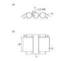
- FIG. 3 is a schematic view showing an example of the heating process, where (a) is a view seen from the front, and (b) is a view seen from above.
- the first roll 3, the second roll 4, and the third roll 5 that are temperature-controllable are provided at predetermined intervals along the transport direction.
- the surface of these rolls is subjected to surface treatment (for example, plating treatment) for the purpose of preventing the laminate from sticking, for example.
- the laminate 10 has one surface (for example, the PVA-based resin layer side) in contact with the first roll 3 and the third roll 5 and the other surface (for example, the base material side). It is conveyed in contact with the second roll 4.
- the first roll 3 and the second roll 4 on the upstream side are heated to the above heating temperature to form a heat roll, and the laminate 10 is heated from the upper side and the lower side.
- the 3rd roll 5 can be set to arbitrary appropriate temperature, for example, it sets to below the glass transition temperature (Tg) of a laminated body, and cools a laminated body. By cooling in this way, it can suppress that a wrinkle generate
- the temperature of the cooling roll is, for example, 30 ° C. to 60 ° C. In the illustrated example, three rolls are used, but it goes without saying that various conditions such as the number of rolls to be used and the number and arrangement of heat rolls can be appropriately changed.
- the laminate is stretched in the longitudinal direction in the heating step.
- the laminate is stretched by a difference in peripheral speed between rolls while being conveyed in the longitudinal direction.
- the laminate is stretched by the heated first roll 3 and second roll 4.
- the first roll 3 and the second roll 4 rotate at different peripheral speeds, and the second roll 4 on the downstream side has a higher peripheral speed than the first roll 3 on the upstream side. Is set.
- the stretching in the heating step is preferably substantially fixed end uniaxial stretching. Specifically, it is preferable to stretch while suppressing shrinkage of the laminate in a direction substantially perpendicular to the stretching direction.
- the fixed end uniaxial stretching in the heating step can contribute to the improvement of the width remaining rate. Further, for example, it is possible to prevent a problem such that the end in the width direction becomes thicker due to contraction than the central portion in the width direction, and to make the thickness uniform in the width direction.
- the first roll 3 and the second roll 4 have a distance L 2 between stretching and a width W ′ of the laminate 10 immediately before the stretching such that L 2 / W ′ ⁇ 0.
- the inter-stretching distance L 2 refers to the distance from the first roll 3 to the second roll 4.
- a laminated body can be hold
- the stretching ratio of stretching in the heating step is preferably more than 1.0 times and 1.4 times or less.
- the stretched laminate of the present invention is preferably stretched 1.5 to 2.5 times, more preferably 1.7 to 2.3 times the original length of the laminate. It is.
- This stretching ratio corresponds to the product of the stretching ratio in the air stretching process and the stretching ratio in the heating process when stretching is performed in the heating process, and the stretching ratio in the air stretching process is performed when stretching is not performed in the heating process. Equivalent to.
- the stretched laminate obtained by the present invention for example, it is possible to finally achieve a higher stretch ratio than stretching the laminate by only stretching in water described later. Specifically, the polyester resin substrate of the stretched laminate is stretched while suppressing orientation.
- the stretched laminate of the present invention is typically used for the production of a polarizing film.
- the stretched laminate of the present invention is appropriately subjected to a treatment for using the PVA resin layer as a polarizing film.
- the treatment for forming the polarizing film include stretching treatment, dyeing treatment, insolubilization treatment, crosslinking treatment, washing treatment, and drying treatment.
- count, order, etc. of these processes are not specifically limited.
- the stretched laminate is stretched in water (stretched in boric acid in water). Specifically, it is stretched in water in a direction parallel to the stretching direction of the laminate.
- the PVA resin layer can be stretched at a temperature lower than the glass transition temperature (typically about 80 ° C.) of the resin base material and the PVA resin layer while suppressing the crystallization. It can be stretched at a high magnification.
- a polarizing film having excellent optical characteristics for example, the degree of polarization
- the “parallel direction” includes the case of 0 ° ⁇ 5.0 °, preferably 0 ° ⁇ 3.0 °, more preferably 0 ° ⁇ 1.0 °. .
- Arbitrary appropriate methods can be employ
- the stretching direction of the stretched laminate is substantially the stretching direction (longitudinal direction) of the above-described air stretching. Stretching of the stretched laminate may be performed in one stage or in multiple stages.
- the stretching in water is preferably carried out by immersing the stretched laminate in a boric acid aqueous solution (stretching in boric acid in water).
- a boric acid aqueous solution as the stretching bath, the PVA resin layer can be provided with rigidity that can withstand the tension applied during stretching and water resistance that does not dissolve in water.
- boric acid can form a tetrahydroxyborate anion in an aqueous solution and crosslink with a PVA resin by hydrogen bonding.
- rigidity and water resistance can be imparted to the PVA-based resin layer, the film can be stretched satisfactorily, and a polarizing film having excellent optical characteristics (for example, polarization degree) can be produced.
- the boric acid aqueous solution is preferably obtained by dissolving boric acid and / or borate in water as a solvent.
- the boric acid concentration is preferably 1 to 10 parts by weight with respect to 100 parts by weight of water. By setting the boric acid concentration to 1 part by weight or more, dissolution of the PVA resin layer can be effectively suppressed, and a polarizing film having higher characteristics can be produced.
- an aqueous solution obtained by dissolving a boron compound such as borax, glyoxal, glutaraldehyde, or the like in a solvent can also be used.
- a dichroic substance typically iodine
- an iodide is added to the stretching bath (boric acid aqueous solution).
- the iodide include potassium iodide, lithium iodide, sodium iodide, zinc iodide, aluminum iodide, lead iodide, copper iodide, barium iodide, calcium iodide, tin iodide, and titanium iodide.
- the concentration of iodide is preferably 0.05 to 15 parts by weight, more preferably 0.5 to 8 parts by weight with respect to 100 parts by weight of water.
- the stretching temperature for stretching in water is preferably 40 ° C. to 85 ° C., more preferably 50 ° C. to 85 ° C. If it is such temperature, it can extend
- the glass transition temperature (Tg) of the polyester resin base material is preferably 60 ° C. or higher in relation to the formation of the PVA resin layer. In this case, when the stretching temperature is lower than 40 ° C., there is a possibility that the stretching cannot be satisfactorily performed even in consideration of plasticization of the polyester-based resin substrate with water.
- the higher the temperature of the stretching bath the higher the solubility of the PVA-based resin layer, and there is a possibility that excellent optical properties cannot be obtained.
- the immersion time of the stretched laminate in the stretching bath is preferably 15 seconds to 5 minutes.
- the maximum draw ratio is preferably 5.0 times or more, more preferably 5.5 times or more, even more preferably with respect to the original length of the laminate (including the draw ratio of the stretched laminate). Is 6.0 times or more.
- the “maximum stretch ratio” refers to a stretch ratio immediately before the stretched laminate breaks, and separately confirms a stretch ratio at which the stretched laminate breaks, and refers to a value 0.2 lower than that value.
- the maximum draw ratio of the laminated body using the said polyester-type resin base material can become higher in the direction which passed through underwater drawing rather than extending
- the dyeing process is typically a process of dyeing a PVA resin layer with a dichroic substance. Preferably, it is performed by adsorbing a dichroic substance to the PVA resin layer.
- adsorption method for example, a method of immersing a PVA resin layer (stretched laminate) in a dye solution containing a dichroic substance, a method of applying the dye solution to a PVA resin layer, and a method of applying the dye solution to PVA And a method of spraying on the resin layer.
- the stretched laminate is immersed in a dyeing solution containing a dichroic substance. It is because a dichroic substance can adsorb
- the dichroic substance examples include iodine and dichroic dyes. Preferably, it is iodine.
- the staining solution is an iodine aqueous solution.
- the amount of iodine is preferably 0.1 to 0.5 parts by weight with respect to 100 parts by weight of water.
- the amount of iodide is preferably 0.02 to 20 parts by weight, more preferably 0.1 to 10 parts by weight, and even more preferably 0.7 to 3 parts by weight per 100 parts by weight of water. .5 parts by weight.
- the liquid temperature during dyeing of the dyeing liquid is preferably 20 ° C. to 50 ° C. in order to suppress dissolution of the PVA resin.
- the immersion time is preferably 5 seconds to 5 minutes in order to ensure the transmittance of the PVA resin layer.
- the staining conditions (concentration, liquid temperature, immersion time) can be set so that the polarization degree or single transmittance of the finally obtained polarizing film is within a predetermined range. In one embodiment, immersion time is set so that the polarization degree of the polarizing film obtained may be 99.98% or more. In another embodiment, the immersion time is set so that the obtained polarizing film has a single transmittance of 40% to 44%.
- the dyeing process is performed before the above-described stretching in water.
- the insolubilization treatment is typically performed by immersing the PVA resin layer in a boric acid aqueous solution.
- a boric acid aqueous solution By performing the insolubilization treatment, water resistance can be imparted to the PVA resin layer.
- the concentration of the boric acid aqueous solution is preferably 1 to 4 parts by weight with respect to 100 parts by weight of water.
- the liquid temperature of the insolubilizing bath (boric acid aqueous solution) is preferably 20 ° C. to 50 ° C.
- the insolubilization treatment is performed before the above-described underwater stretching or the above-described dyeing treatment.
- the cross-linking treatment is typically performed by immersing the PVA resin layer in an aqueous boric acid solution.
- the concentration of the boric acid aqueous solution is preferably 1 to 4 parts by weight with respect to 100 parts by weight of water.
- the blending amount of iodide is preferably 1 to 5 parts by weight with respect to 100 parts by weight of water.
- the liquid temperature of the crosslinking bath is preferably 20 ° C. to 50 ° C.
- the crosslinking treatment is performed before the underwater stretching.
- the dyeing process, the crosslinking process and the underwater stretching are performed in this order.
- the cleaning treatment is typically performed by immersing the PVA resin layer in an aqueous potassium iodide solution.
- the drying temperature in the drying treatment is preferably 30 ° C. to 100 ° C.
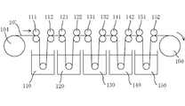
- FIG. 4 is a schematic view showing an example of a method for producing a polarizing film.
- the stretched laminate 10 ′ is fed out from the feeding unit 101, immersed in a boric acid aqueous solution bath 110 by rolls 111 and 112 (insolubilization treatment), and then dichroic (iodine) and potassium iodide by rolls 121 and 122.
- dichroic (iodine) and potassium iodide by rolls 121 and 122.
- an aqueous solution bath 120 dichroic (iodine) and potassium iodide
- the rolls 131 and 132 are immersed in a bath 130 of an aqueous solution of boric acid and potassium iodide (crosslinking treatment).
- the stretched laminate 10 ′ is stretched by applying tension in the machine direction (longitudinal direction) with rolls 141 and 142 having different speed ratios while being immersed in a bath 140 of a boric acid aqueous solution (stretching in water).
- the stretched laminate 10 ′ stretched in water is immersed in a bath 150 of a potassium iodide aqueous solution by rolls 151 and 152 (cleaning treatment) and subjected to a drying treatment (not shown). Thereafter, the stretched laminate 10 ′ is wound up by the winding unit 160.
- a polarizing film is formed on the resin substrate by subjecting the stretched laminate of the present invention to the above-described treatments.
- This polarizing film is substantially a PVA resin film in which a dichroic substance is adsorbed and oriented.
- the thickness of the polarizing film is preferably 10 ⁇ m or less, more preferably 7 ⁇ m or less, and still more preferably 5 ⁇ m or less.
- the thickness of the polarizing film is preferably 0.5 ⁇ m or more, more preferably 1.5 ⁇ m or more.
- the polarizing film preferably exhibits absorption dichroism at any wavelength of 380 nm to 780 nm.
- the single transmittance of the polarizing film is preferably 40.0% or more, more preferably 41.0% or more, and further preferably 42.0% or more.
- the polarization degree of the polarizing film is preferably 99.8% or more, more preferably 99.9% or more, and further preferably 99.95% or more.
- any appropriate method can be adopted as a method of using the polarizing film. Specifically, it may be used in a state integrated with the resin base material, or may be transferred from the resin base material to another member for use.
- the optical laminate of the present invention has the polarizing film.
- 5 (a) and 5 (b) are schematic cross-sectional views of an optical film laminate according to a preferred embodiment of the present invention.
- the optical film laminate 100 includes a resin substrate 11 ′, a polarizing film 12 ′, an adhesive layer 13, and a separator 14 in this order.
- the optical film laminate 200 includes a resin substrate 11 ′, a polarizing film 12 ′, an adhesive layer 15, an optical function film 16, an adhesive layer 13, and a separator 14 in this order.
- the resin base material is used as it is as an optical member without being peeled from the obtained polarizing film 12 ′.
- Resin base material 11 ' can function as a protective film of polarizing film 12', for example.
- FIG. 6 (a) and 6 (b) are schematic cross-sectional views of an optical functional film laminate according to another preferred embodiment of the present invention.
- the optical functional film laminate 300 includes the separator 14, the pressure-sensitive adhesive layer 13, the polarizing film 12 ', the adhesive layer 15, and the optical functional film 16 in this order.
- the second optical functional film 16 ′ is provided between the polarizing film 12 ′ and the separator 14 with the adhesive layer 13 interposed therebetween. .
- the resin base material is removed.
- each layer constituting the optical laminate of the present invention is not limited to the illustrated example, and any appropriate pressure-sensitive adhesive layer or adhesive layer is used.
- the pressure-sensitive adhesive layer is typically formed of an acrylic pressure-sensitive adhesive.
- the adhesive layer is typically formed of a vinyl alcohol adhesive.
- the optical functional film can function as, for example, a polarizing film protective film or a retardation film.
- Example 1 Water-based urethane resin (Daiichi Kogyo Seiyaku Co., Ltd., trade name: Superflex 210R, solid content: 35%), oxazoline-based cross-linking agent (manufactured by Nippon Shokubai Co., Ltd., trade name: Epocross WS700, solid content: 25% ), Conductive material (manufactured by Agfa, trade name: Olgacon LBS, solid content: 1.2%), ammonia water having a concentration of 1% and water in a weight ratio of 9.03: 1.00: 18.1: 0.060. : 39.5 mixed solution was prepared.
- the obtained mixed solution was dried on one side of a 200 ⁇ m-thick amorphous polyethylene terephthalate (A-PET) film (Tg: 70 ° C., Mitsubishi Plastics, trade name: SH046) after drying. It applied so that thickness might be set to 1 micrometer. Subsequently, the A-PET film was stretched twice in the transverse direction at 115 ° C. while being conveyed in the longitudinal direction. Next, an aqueous solution of polyvinyl alcohol (degree of polymerization: 4200, degree of saponification: 99.2 mol%) is applied to the other surface of the A-PET film, and dried at 60 ° C. to obtain a PVA system having a thickness of 10 ⁇ m. A resin layer was formed. In this way, a laminate having a width (W) of 1500 mm was obtained.
- A-PET amorphous polyethylene terephthalate
- the laminated body obtained by the roll pair provided in each of the inlet and outlet of temperature-controllable oven (length L 1 : 900 mm, L 1 / W: 0.6 in the conveying direction) was stretched 1.5 times in the longitudinal direction with a peripheral speed difference between these rolls (air stretching step).
- the temperature and the air volume of the oven were appropriately adjusted, and the maximum temperature reached of the laminate during stretching was set to 88 ° C.
- the temperature of the laminate during stretching was confirmed by attaching a heat label (product number: 6R-65 or 6R-99, manufactured by Micron Corporation) to the surface of the laminate. Subsequently, as shown in FIG.
- the surface was subjected to hard chrome plating, and the laminate was passed through three iron rolls capable of temperature control.
- the PVA-based resin layer surface of the laminate was brought into contact with the first roll and the third roll, and the other surface (base material side) was brought into contact with the second roll.
- the surface temperature of the 1st roll and the 2nd roll was 120 degreeC
- the surface temperature of the 3rd roll was 50 degreeC.
- the first roll and the second roll did not have a peripheral speed difference.
- the width W ′ of the laminate immediately before passing through the first roll is 1220 mm
- the distance L 2 from the first roll to contact with the second roll is 37 mm
- the obtained stretched laminate was immersed in a 3 wt% boric acid aqueous solution (insolubilized bath) having a liquid temperature of 30 ° C for 30 seconds (insolubilization treatment). Subsequently, the single transmittance (Ts) of the polarizing film finally obtained in a dyeing bath (iodine aqueous solution obtained by mixing iodine and potassium iodide in water at a weight ratio of 1: 7) at a liquid temperature of 30 ° C. ) was 40 to 44% (dyeing treatment).
- a dyeing bath iodine aqueous solution obtained by mixing iodine and potassium iodide in water at a weight ratio of 1: 7
- Example 2-1 When producing the stretched laminate, a polarizing film was obtained in the same manner as in Example 1 except that the stretch ratio was 1.8 times. The thickness of the obtained polarizing film was 4.1 ⁇ m.
- Example 2-2 A polarizing film was obtained in the same manner as in Example 1 except that a stretched laminate was produced as follows. The thickness of the obtained polarizing film was 4.0 ⁇ m. (Production of stretched laminate) As shown in FIG. 2, the laminated body obtained by the roll pair provided in each of the inlet and outlet of temperature-controllable oven (length L 1 : 900 mm, L 1 / W: 0.6 in the conveying direction) was stretched 1.6 times in the longitudinal direction with a peripheral speed difference between these rolls (air stretching step). At that time, the temperature and air volume of the oven were adjusted as appropriate, and the maximum temperature reached during stretching was 88 ° C. Subsequently, as shown in FIG.
- the surface was subjected to hard chrome plating, and the laminate was passed through three iron rolls capable of temperature control (heating process).
- the PVA-based resin layer surface of the laminate was brought into contact with the first roll and the third roll, and the other surface (base material side) was brought into contact with the second roll.
- the surface temperature of the 1st roll and the 2nd roll was 120 degreeC
- the surface temperature of the 3rd roll was 50 degreeC.
- the first roll and the second roll were stretched 1.13 times with a peripheral speed difference.
- the width W ′ of the laminate immediately before passing through the first roll is 1160 mm
- the distance L 2 from the first roll to the contact with the second roll is 35 mm
- L 2 / W ′ was 0.03.
- Example 2-3 A polarizing film was obtained in the same manner as in Example 2-2 except that when the stretched laminate was produced, the stretch ratio in the air stretching step was 1.4 times and the stretch ratio in the heating step was 1.29 times. The thickness of the obtained polarizing film was 4.0 ⁇ m.
- Example 3-1 In producing the stretched laminate, a polarizing film was obtained in the same manner as in Example 1 except that the stretch ratio was 2.0. The thickness of the obtained polarizing film was 4.0 ⁇ m.
- Example 3-2 A polarizing film was obtained in the same manner as in Example 2-2 except that when the stretched laminate was produced, the stretch ratio in the air stretching step was 1.8 times and the stretch ratio in the heating step was 1.11 times. The thickness of the obtained polarizing film was 3.9 ⁇ m.
- Example 3-3 A polarizing film was obtained in the same manner as in Example 2-2 except that when the stretched laminate was produced, the stretch ratio in the air stretching step was 1.6 times and the stretch ratio in the heating step was 1.25 times. The thickness of the obtained polarizing film was 3.9 ⁇ m.
- Example 4 When producing the stretched laminate, a polarizing film was obtained in the same manner as in Example 1 except that the stretch ratio was 2.2. The thickness of the obtained polarizing film was 4.1 ⁇ m.
- Example 5 When producing the stretched laminate, a polarizing film was obtained in the same manner as in Example 1 except that the stretch ratio was 2.5. The thickness of the obtained polarizing film was 4.1 ⁇ m.
- Example 6-1 A polarizing film was obtained in the same manner as in Example 2-2 except that the temperature of the oven was adjusted so that the maximum temperature reached in the air during stretching was 99 ° C. during the production of the stretched laminate. The thickness of the obtained polarizing film was 4.2 ⁇ m.
- Example 6-2 A polarizing film was obtained in the same manner as in Example 2-2, except that the temperature of the oven was adjusted so that the maximum temperature reached during air stretching was 71 ° C. during the production of the stretched laminate. The thickness of the obtained polarizing film was 3.6 ⁇ m.
- Example 6-3 When producing the stretched laminate, a polarizing film was obtained in the same manner as in Example 2-2 except that the surface temperature of the first roll and the second roll was 110 ° C. in the heating step. The thickness of the obtained polarizing film was 4.0 ⁇ m.
- Example 6-4 When producing the stretched laminate, a polarizing film was obtained in the same manner as in Example 2-2 except that the surface temperature of the first roll and the second roll was set to 130 ° C. in the heating step. The thickness of the obtained polarizing film was 4.0 ⁇ m.
- Example 6-5 Upon preparation of the stretched laminate, except that the transport direction of the oven length L 1 was 600mm (L 1 /W:0.4) in air stretching step, the polarizing film in the same manner as in Example 2-2 Obtained. The thickness of the obtained polarizing film was 4.0 ⁇ m.
- Example 6-6 Upon preparation of the stretched laminate, except that the stretching distance L 2 was 115 mm (L 2 / W 'to 0.1) in the heating step, to obtain a polarizing film in the same manner as in Example 2-2. The thickness of the obtained polarizing film was 3.9 ⁇ m.
- Example 1 A polarizing film was obtained in the same manner as in Example 1 except that the heating step was not performed when the stretched laminate was produced. The thickness of the obtained polarizing film was 4.5 ⁇ m.
- Example 2 A polarizing film was obtained in the same manner as in Example 2-1, except that the heating step was not performed in the production of the stretched laminate. The thickness of the obtained polarizing film was 4.1 ⁇ m.
- Example 3 A polarizing film was obtained in the same manner as in Example 3-1, except that the heating step was not performed in the production of the stretched laminate.
- the thickness of the obtained polarizing film was 4.0 ⁇ m.
- Example 4 A polarizing film was obtained in the same manner as in Example 4 except that the heating step was not performed when the stretched laminate was produced.
- the thickness of the obtained polarizing film was 4.1 ⁇ m.
- Example 5 A polarizing film was obtained in the same manner as in Example 5 except that the heating step was not performed when the stretched laminate was produced.
- the thickness of the obtained polarizing film was 4.1 ⁇ m.
- Comparative Example 6 A polarizing film was obtained in the same manner as in Comparative Example 1 except that the temperature of the oven was adjusted so that the maximum temperature reached during air stretching was 121 ° C. The thickness of the obtained polarizing film was 4.3 ⁇ m.
- Comparative Example 7 A polarizing film was obtained in the same manner as in Comparative Example 2 except that the temperature of the oven was adjusted so that the maximum temperature reached during air stretching was 121 ° C. The thickness of the obtained polarizing film was 4.5 ⁇ m.
- Comparative Example 8 A polarizing film was obtained in the same manner as in Comparative Example 3 except that the temperature of the oven was adjusted so that the maximum temperature reached during air stretching was 121 ° C. The thickness of the obtained polarizing film was 4.4 ⁇ m.
- Comparative Example 9 A polarizing film was obtained in the same manner as in Comparative Example 4 except that the temperature of the oven was adjusted so that the maximum temperature reached during air stretching was 121 ° C. The thickness of the obtained polarizing film was 4.6 ⁇ m.
- Comparative Example 10 A polarizing film was obtained in the same manner as in Comparative Example 5 except that the temperature of the oven was adjusted so that the maximum temperature reached during air stretching was 121 ° C. The thickness of the obtained polarizing film was 4.3 ⁇ m.
- Example 1 the width remaining ratio of the obtained stretched laminate and the laminate before stretching of the polarizing film was measured.
- the measurement results are shown in Table 1 together with the maximum draw ratio (relative to the laminate before drawing).
- the polarization degree of the polarizing film obtained in each example and comparative example was measured.
- an adhesive 3 aqueous solution of GOHSEPHIMER Z200 manufactured by Nihon Gosei Co., Ltd.
- a triacetylcellulose (TAC) film having a thickness of 80 ⁇ m manufactured by FUJIFILM Corporation.
- the product name “TD80UL” and the thickness of 80 ⁇ m were bonded together and heated at 60 ° C. for 5 minutes, and then the substrate (A-PET film) was peeled off.
- the polarizing film was transferred to a TAC film and used for measurement of the degree of polarization.
- the measurement method of the degree of polarization is as follows, and Table 1 shows the results of the single transmittance when the degree of polarization is 99.99%.
- Measurement method of degree of polarization Using a UV-visible spectrophotometer (manufactured by JASCO Corporation, product name “V7100”), the single transmittance (Ts), parallel transmittance (Tp) and orthogonal transmittance (Tc) of the polarizing film are measured, and the degree of polarization is measured. (P) was determined by the following equation.
- Polarization degree (P) (%) ⁇ (Tp ⁇ Tc) / (Tp + Tc) ⁇ 1/2 ⁇ 100 Note that Ts, Tp, and Tc are Y values measured with a two-degree field of view (C light source) of JIS Z 8701 and corrected for visibility.
- Example 1 the width remaining rate and the single unit transmittance are high, whereas the single unit transmittance is low in Comparative Examples 1-5 and 11, and the width remaining rate is low in Comparative Example 6-10.
- Comparative Example 1 Comparative Example 1 and Comparative Example 10 having a maximum draw ratio of 5.4
- Example 1 Comparative Example 1 and Comparative Example 6 have sufficient stretchability of the A-PET film.
- Comparative Example 10 the stretchability of the PVA resin layer is not sufficient.
- the stretched laminate of the present invention is suitably used for the production of a polarizing film.
- the obtained polarizing film has high optical characteristics and can be suitably used for, for example, a liquid crystal panel or an organic EL panel.
Landscapes
- Physics & Mathematics (AREA)
- Nonlinear Science (AREA)
- General Physics & Mathematics (AREA)
- Optics & Photonics (AREA)
- Mathematical Physics (AREA)
- Chemical & Material Sciences (AREA)
- Crystallography & Structural Chemistry (AREA)
- Polarising Elements (AREA)
- Shaping By String And By Release Of Stress In Plastics And The Like (AREA)
Abstract
Description
好ましい実施形態においては、上記空中延伸の延伸倍率が1.4倍以上である。
好ましい実施形態においては、上記加熱工程において上記積層体を長手方向に延伸する。この延伸は、好ましくは、実質的に固定端一軸延伸である。
好ましい実施形態においては、上記加熱工程において、上記積層体を長手方向に搬送しながら、ロール間の周速差により延伸し、該延伸間距離L2と、該延伸直前の積層体の幅W’とが、L/W’≦0.12の関係を満足する。
好ましい実施形態においては、1.7倍~2.3倍に延伸する。
本発明の別の局面によれば、延伸積層体が提供される。この延伸積層体は、上記製造方法により製造される。
本発明のさらに別の局面によれば、偏光膜の製造方法が提供される。この偏光膜の製造方法は、上記延伸積層体を用いる。
好ましい実施形態においては、上記延伸積層体をホウ酸水溶液中で延伸する。
A.製造方法
本発明の延伸積層体の製造方法は、長尺状のポリエステル系樹脂基材上にポリビニルアルコール系樹脂層を形成して積層体を作製する工程と、この積層体を長手方向に搬送しながら、ロール間の周速差により100℃以下で空中延伸する工程と、この延伸された積層体を110℃以上に加熱する工程とを含む。以下、各々の工程について説明する。
図1は、本発明の好ましい実施形態による積層体の部分断面図である。積層体10は、ポリエステル系樹脂基材11とポリビニルアルコール系樹脂層12とを有する。積層体10は、長尺状のポリエステル系樹脂基材にポリビニルアルコール系樹脂層12を形成することにより作製される。ポリビニルアルコール系樹脂層12の形成方法としては、任意の適切な方法が採用され得る。好ましくは、ポリエステル系樹脂基材11上に、ポリビニルアルコール系樹脂(以下、「PVA系樹脂」という)を含む塗布液を塗布し、乾燥することにより、PVA系樹脂層12を形成する。
上記空中延伸工程では、上記積層体をその長手方向に搬送しながら、ロール間の周速差により延伸する。具体的には、ロール間の周速差により積層体に張力を付与し、長手方向に一軸延伸する。
加熱工程では、上記空中延伸された積層体を110℃以上に加熱する。加熱温度は、好ましくは120℃以上である。一方、加熱温度は好ましくは160℃以下である。空中延伸された積層体をこのような温度で加熱することにより、PVA系樹脂の結晶性を向上させることができる。結晶性を向上させることにより、後述の水中延伸において、PVA系樹脂層が水に溶解して配向性が低下するのを防止することができる。その結果、優れた光学特性を有する偏光膜を作製することができる。
本発明の延伸積層体は、積層体の元長に対して、1.5倍~2.5倍に延伸されていることが好ましく、より好ましくは1.7倍~2.3倍である。この延伸倍率は、加熱工程において延伸を行う場合は、空中延伸工程の延伸倍率と加熱工程の延伸倍率との積に相当し、加熱工程において延伸を行わない場合は、空中延伸工程の延伸倍率に相当する。本発明により得られる延伸積層体を用いることにより、例えば、上記積層体を後述の水中延伸のみで延伸するよりも、最終的により高い延伸倍率を達成することができる。具体的には、延伸積層体のポリエステル系樹脂基材は、配向を抑制しながら延伸されている。配向性が高いほど延伸張力が大きくなり、安定的な延伸が困難となったり、樹脂基材が破断したりするが、配向が抑制されていることで、最終的により高い延伸倍率を達成することができる。その結果、優れた光学特性(例えば、偏光度)を有する偏光膜を作製することができる。
本発明の延伸積層体は、代表的には、偏光膜の製造に供される。具体的には、本発明の延伸積層体は、そのPVA系樹脂層を偏光膜とするための処理が、適宜施される。偏光膜とするための処理としては、例えば、延伸処理、染色処理、不溶化処理、架橋処理、洗浄処理、乾燥処理等が挙げられる。なお、これらの処理の回数、順序等は、特に限定されない。
好ましい実施形態においては、上記延伸積層体を水中延伸(ホウ酸水中延伸)する。具体的には、上記積層体の延伸方向と平行な方向に水中延伸する。水中延伸によれば、上記樹脂基材やPVA系樹脂層のガラス転移温度(代表的には、80℃程度)よりも低い温度で延伸し得、PVA系樹脂層を、その結晶化を抑えながら、高倍率に延伸することができる。その結果、優れた光学特性(例えば、偏光度)を有する偏光膜を作製することができる。なお、本明細書において「平行な方向」とは、0°±5.0°である場合を包含し、好ましくは0°±3.0°、さらに好ましくは0°±1.0°である。
上記染色処理は、代表的には、PVA系樹脂層を二色性物質で染色する処理である。好ましくは、PVA系樹脂層に二色性物質を吸着させることにより行う。当該吸着方法としては、例えば、二色性物質を含む染色液にPVA系樹脂層(延伸積層体)を浸漬する方法、PVA系樹脂層に当該染色液を塗工する方法、当該染色液をPVA系樹脂層に噴霧する方法等が挙げられる。好ましくは、二色性物質を含む染色液に延伸積層体を浸漬する方法である。二色性物質が良好に吸着し得るからである。
上述のとおり、本発明の延伸積層体に上記各処理を施すことにより上記樹脂基材上に偏光膜が形成される。この偏光膜は、実質的には、二色性物質が吸着配向されたPVA系樹脂膜である。偏光膜の厚みは、好ましくは10μm以下であり、より好ましくは7μm以下、さらに好ましくは5μm以下である。一方、偏光膜の厚みは、好ましくは0.5μm以上、より好ましくは1.5μm以上である。偏光膜は、好ましくは、波長380nm~780nmのいずれかの波長で吸収二色性を示す。偏光膜の単体透過率は、好ましくは40.0%以上、より好ましくは41.0%以上、さらに好ましくは42.0%以上である。偏光膜の偏光度は、好ましくは99.8%以上、より好ましくは99.9%以上、さらに好ましくは99.95%以上である。
本発明の光学積層体は、上記偏光膜を有する。図5(a)および(b)は、本発明の好ましい実施形態による光学フィルム積層体の概略断面図である。光学フィルム積層体100は、樹脂基材11’と偏光膜12’と粘着剤層13とセパレータ14とをこの順で有する。光学フィルム積層体200は、樹脂基材11’と偏光膜12’と接着剤層15と光学機能フィルム16と粘着剤層13とセパレータ14とをこの順で有する。本実施形態では、上記樹脂基材を得られた偏光膜12’から剥離せずに、そのまま光学部材として用いている。樹脂基材11’は、例えば、偏光膜12’の保護フィルムとして機能し得る。
1.厚み
デジタルマイクロメーター(アンリツ社製、製品名「KC-351C」)を用いて測定した。
2.ガラス転移温度(Tg)
JIS K 7121に準じて測定した。
水系ウレタン樹脂(第一工業製薬(株)製、商品名:スーパーフレックス210R、固形分:35%)、オキサゾリン系架橋剤(日本触媒(株)製、商品名:エポクロスWS700、固形分:25%)、導電材(アグファ製、商品名:オルガコンLBS、固形分:1.2%)、濃度1%のアンモニア水および水を、重量比9.03:1.00:18.1:0.060:39.5で混合した混合液を調製した。
得られた混合液を、厚み200μmで長尺状の非晶質ポリエチレンテレフタレート(A-PET)フィルム(Tg:70℃、三菱樹脂社製、商品名:SH046)の一方の面に、乾燥後の厚みが1μmとなるように塗布した。
続いて、A-PETフィルムをその長手方向に搬送しながら、115℃で横方向に2倍に延伸した。
次に、A-PETフィルムのもう一方の面に、ポリビニルアルコール(重合度:4200、ケン化度:99.2モル%)の水溶液を塗布し、60℃で乾燥して、厚み10μmのPVA系樹脂層を形成した。
このようにして、幅(W)1500mmの積層体を得た。
図2に示すように、温度調節可能なオーブン(搬送方向の長さL1:900mm、L1/W:0.6)の入口と出口のそれぞれに設けられたロール対に得られた積層体を挟持させ、これらのロール間に周速差を持たせて長手方向に1.5倍に延伸した(空中延伸工程)。その際、オーブンの温度・風量を適宜調整し、延伸時の積層体の最高到達温度を88℃とした。なお、延伸時の積層体の温度(最高到達温度)は、積層体の表面にヒートラベル(ミクロン株式会社製、品番:6R-65もしくは6R-99)を貼付しておくことにより確認した。
続いて、図3に示すように、表面にハードクロムメッキが施され、温度制御可能な3本の鉄ロールに積層体を通過させた。ここで、積層体のPVA系樹脂層面を第1のロールおよび第3のロールに接触させ、もう一方の面(基材側)を第2のロールに接触させた。第1のロールおよび第2のロールの表面温度を120℃とし、第3のロールの表面温度を50℃とした。第1のロールと第2のロールとは周速差を持たせなかった。第1のロールを通過する直前の積層体の幅W’は1220mmであり、第1のロールから積層体が離れて第2のロールに接するまでの距離L2は37mmであり、L2/W’は0.03であった。
このようにして、延伸積層体を得た。
続いて、液温30℃の染色浴(水にヨウ素とヨウ化カリウムとを重量比1:7で配合して得られたヨウ素水溶液)に、最終的に得られる偏光膜の単体透過率(Ts)が40~44%となるように浸漬した(染色処理)。
続いて、液温30℃のホウ酸3重量%、ヨウ化カリウム3重量%を含む水溶液(架橋浴)に30秒間浸漬した(架橋処理)。
その後、積層体を、液温70℃でホウ酸4重量%、ヨウ化カリウム5重量%含む水溶液中で、周速の異なる複数セットのロール間で、縦方向(長手方向)に破断する直前まで一軸延伸した(ホウ酸水中延伸)。
その後、液温30℃のヨウ化カリウム4重量%水溶液(洗浄浴)に浸漬した後、60℃の温風で乾燥した(洗浄・乾燥処理)。
このようにして、厚み4.5μmの偏光膜を得た。
延伸積層体の作製に際し、延伸倍率を1.8倍としたこと以外は、実施例1と同様にして偏光膜を得た。得られた偏光膜の厚みは、4.1μmであった。
以下のようにして、延伸積層体を作製したこと以外は、実施例1と同様にして偏光膜を得た。得られた偏光膜の厚みは、4.0μmであった。
(延伸積層体の作製)
図2に示すように、温度調節可能なオーブン(搬送方向の長さL1:900mm、L1/W:0.6)の入口と出口のそれぞれに設けられたロール対に得られた積層体を挟持させ、これらのロール間に周速差を持たせて長手方向に1.6倍に延伸した(空中延伸工程)。その際、オーブンの温度・風量を適宜調整し、延伸時の最高到達温度を88℃とした。
続いて、図3に示すように、表面にハードクロムメッキが施され、温度制御可能な3本の鉄ロールに積層体を通過させた(加熱工程)。ここで、積層体のPVA系樹脂層面を第1のロールおよび第3のロールに接触させ、もう一方の面(基材側)を第2のロールに接触させた。第1のロールおよび第2のロールの表面温度を120℃とし、第3のロールの表面温度を50℃とした。第1のロールと第2のロールとの間で周速差を持たせて1.13倍に延伸した。また、第1のロールを通過する直前の積層体の幅W’は1160mmであり、第1のロールから積層体が離れて第2のロールに接するまでの距離L2は35mmであり、L2/W’は0.03であった。
延伸積層体の作製に際し、空中延伸工程における延伸倍率1.4倍とし、加熱工程における延伸倍率を1.29倍としたこと以外は、実施例2-2と同様にして偏光膜を得た。得られた偏光膜の厚みは、4.0μmであった。
延伸積層体の作製に際し、延伸倍率を2.0倍としたこと以外は、実施例1と同様にして偏光膜を得た。得られた偏光膜の厚みは、4.0μmであった。
延伸積層体の作製に際し、空中延伸工程における延伸倍率1.8倍とし、加熱工程における延伸倍率を1.11倍としたこと以外は、実施例2-2と同様にして偏光膜を得た。得られた偏光膜の厚みは、3.9μmであった。
延伸積層体の作製に際し、空中延伸工程における延伸倍率1.6倍とし、加熱工程における延伸倍率を1.25倍としたこと以外は、実施例2-2と同様にして偏光膜を得た。得られた偏光膜の厚みは、3.9μmであった。
延伸積層体の作製に際し、延伸倍率を2.2倍としたこと以外は、実施例1と同様にして偏光膜を得た。得られた偏光膜の厚みは、4.1μmであった。
延伸積層体の作製に際し、延伸倍率を2.5倍としたこと以外は、実施例1と同様にして偏光膜を得た。得られた偏光膜の厚みは、4.1μmであった。
延伸積層体の作製に際し、空中延伸時の最高到達温度が99℃となるようにオーブンの温度調節をしたこと以外は、実施例2-2と同様にして偏光膜を得た。得られた偏光膜の厚みは、4.2μmであった。
延伸積層体の作製に際し、空中延伸時の最高到達温度が71℃となるようにオーブンの温度調節をしたこと以外は、実施例2-2と同様にして偏光膜を得た。得られた偏光膜の厚みは、3.6μmであった。
延伸積層体の作製に際し、加熱工程において第1のロールおよび第2のロールの表面温度を110℃としたこと以外は、実施例2-2と同様にして偏光膜を得た。得られた偏光膜の厚みは、4.0μmであった。
延伸積層体の作製に際し、加熱工程において第1のロールおよび第2のロールの表面温度を130℃としたこと以外は、実施例2-2と同様にして偏光膜を得た。得られた偏光膜の厚みは、4.0μmであった。
延伸積層体の作製に際し、空中延伸工程においてオーブンの搬送方向の長さL1を600mm(L1/W:0.4)としたこと以外は、実施例2-2と同様にして偏光膜を得た。得られた偏光膜の厚みは、4.0μmであった。
延伸積層体の作製に際し、加熱工程において延伸間距離L2を115mm(L2/W’を0.1)としたこと以外は、実施例2-2と同様にして偏光膜を得た。得られた偏光膜の厚みは、3.9μmであった。
延伸積層体の作製に際し、加熱工程を行わなかったこと以外は、実施例1と同様にして偏光膜を得た。得られた偏光膜の厚みは、4.5μmであった。
延伸積層体の作製に際し、加熱工程を行わなかったこと以外は、実施例2-1と同様にして偏光膜を得た。得られた偏光膜の厚みは、4.1μmであった。
延伸積層体の作製に際し、加熱工程を行わなかったこと以外は、実施例3-1と同様にして偏光膜を得た。得られた偏光膜の厚みは、4.0μmであった。
延伸積層体の作製に際し、加熱工程を行わなかったこと以外は、実施例4と同様にして偏光膜を得た。得られた偏光膜の厚みは、4.1μmであった。
延伸積層体の作製に際し、加熱工程を行わなかったこと以外は、実施例5と同様にして偏光膜を得た。得られた偏光膜の厚みは、4.1μmであった。
空中延伸時の最高到達温度が121℃となるようにオーブンの温度調節をしたこと以外は、比較例1と同様にして偏光膜を得た。得られた偏光膜の厚みは、4.3μmであった。
空中延伸時の最高到達温度が121℃となるようにオーブンの温度調節をしたこと以外は、比較例2と同様にして偏光膜を得た。得られた偏光膜の厚みは、4.5μmであった。
空中延伸時の最高到達温度が121℃となるようにオーブンの温度調節をしたこと以外は、比較例3と同様にして偏光膜を得た。得られた偏光膜の厚みは、4.4μmであった。
空中延伸時の最高到達温度が121℃となるようにオーブンの温度調節をしたこと以外は、比較例4と同様にして偏光膜を得た。得られた偏光膜の厚みは、4.6μmであった。
空中延伸時の最高到達温度が121℃となるようにオーブンの温度調節をしたこと以外は、比較例5と同様にして偏光膜を得た。得られた偏光膜の厚みは、4.3μmであった。
延伸積層体の作製に際し、テンター方式の延伸機(Bruckner社製、製品名「KARO IV」)を用いて2.0倍の固定端一軸延伸により空中延伸したこと、空中延伸時の最高到達温度が121℃となるようにオーブンの温度調節をしたこと、および、加熱工程を行わなかったこと以外は、実施1と同様にして偏光膜を得た。得られた偏光膜の厚みは2.8μmであった。
偏光度の測定方法は以下のとおりであり、偏光度99.99%における単体透過率の結果を表1に示す。
(偏光度の測定方法)
紫外可視分光光度計(日本分光社製、製品名「V7100」)を用いて、偏光膜の単体透過率(Ts)、平行透過率(Tp)および直交透過率(Tc)を測定し、偏光度(P)を次式により求めた。
偏光度(P)(%)={(Tp-Tc)/(Tp+Tc)}1/2×100
なお、上記Ts、TpおよびTcは、JIS Z 8701の2度視野(C光源)により測定し、視感度補正を行ったY値である。

2 ロール
3 第1のロール
4 第2のロール
5 第3のロール
9 オーブン
10 積層体
10’ 延伸積層体
11 ポリエステル系樹脂基材
12 PVA系樹脂層
Claims (9)
- 長尺状のポリエステル系樹脂基材上にポリビニルアルコール系樹脂層を形成して積層体を作製する工程と、
該積層体を長手方向に搬送しながら、ロール間の周速差により100℃以下で空中延伸する工程と、
該延伸された積層体を110℃以上に加熱する工程とを含み、
該延伸工程において、延伸間距離L1と、該積層体の幅Wとが、L1/W≧0.3の関係を満足する、
延伸積層体の製造方法。 - 前記空中延伸の延伸倍率が1.4倍以上である、請求項1に記載の製造方法。
- 前記加熱工程において前記積層体を長手方向に延伸する、請求項1に記載の製造方法。
- 前記延伸が、実質的に固定端一軸延伸である、請求項3に記載の製造方法。
- 前記加熱工程において、前記積層体を長手方向に搬送しながら、ロール間の周速差により延伸し、該延伸間距離L2と、該延伸直前の積層体の幅W’とが、L/W’≦0.12の関係を満足する、請求項3または4に記載の製造方法。
- 1.7倍~2.3倍に延伸する、請求項1に記載の製造方法。
- 請求項1に記載の製造方法により製造される、延伸積層体。
- 請求項7に記載の延伸積層体を用いる、偏光膜の製造方法。
- 前記延伸積層体をホウ酸水溶液中で延伸する、請求項8に記載の製造方法。
Priority Applications (3)
| Application Number | Priority Date | Filing Date | Title |
|---|---|---|---|
| CN201480078033.6A CN106233170B (zh) | 2014-04-14 | 2014-04-14 | 拉伸层叠体的制造方法 |
| KR1020167028459A KR102038747B1 (ko) | 2014-04-14 | 2014-04-14 | 연신 적층체의 제조 방법 |
| PCT/JP2014/060615 WO2015159343A1 (ja) | 2014-04-14 | 2014-04-14 | 延伸積層体の製造方法 |
Applications Claiming Priority (1)
| Application Number | Priority Date | Filing Date | Title |
|---|---|---|---|
| PCT/JP2014/060615 WO2015159343A1 (ja) | 2014-04-14 | 2014-04-14 | 延伸積層体の製造方法 |
Publications (1)
| Publication Number | Publication Date |
|---|---|
| WO2015159343A1 true WO2015159343A1 (ja) | 2015-10-22 |
Family
ID=54323594
Family Applications (1)
| Application Number | Title | Priority Date | Filing Date |
|---|---|---|---|
| PCT/JP2014/060615 Ceased WO2015159343A1 (ja) | 2014-04-14 | 2014-04-14 | 延伸積層体の製造方法 |
Country Status (3)
| Country | Link |
|---|---|
| KR (1) | KR102038747B1 (ja) |
| CN (1) | CN106233170B (ja) |
| WO (1) | WO2015159343A1 (ja) |
Families Citing this family (1)
| Publication number | Priority date | Publication date | Assignee | Title |
|---|---|---|---|---|
| JP7534904B2 (ja) * | 2020-09-28 | 2024-08-15 | 日東電工株式会社 | 延伸フィルムの製造方法 |
Citations (8)
| Publication number | Priority date | Publication date | Assignee | Title |
|---|---|---|---|---|
| US4388375A (en) * | 1981-11-24 | 1983-06-14 | American Hoechst Corporation | Polyester based polarizer |
| US4659523A (en) * | 1984-11-30 | 1987-04-21 | American Hoechst Corporation | Production of iodine stainable polyester polarizer film |
| JP2002326278A (ja) * | 2001-05-07 | 2002-11-12 | Nitto Denko Corp | 配向フィルムの製造方法、偏光フィルム、偏光板および液晶表示装置 |
| JP2004341515A (ja) * | 2003-04-25 | 2004-12-02 | Nitto Denko Corp | 偏光フィルムの製造方法、偏光フィルムおよびそれを用いた画像表示装置 |
| WO2012074063A1 (ja) * | 2010-12-02 | 2012-06-07 | 日東電工株式会社 | 偏光板の製造方法 |
| WO2012096079A1 (ja) * | 2011-01-12 | 2012-07-19 | 住友化学株式会社 | 偏光性積層フィルムの製造方法および偏光板の製造方法 |
| JP2013190464A (ja) * | 2012-03-12 | 2013-09-26 | Konica Minolta Inc | 偏光板の製造方法、偏光板及び液晶表示装置 |
| JP2014074786A (ja) * | 2012-10-04 | 2014-04-24 | Nitto Denko Corp | 延伸積層体の製造方法 |
Family Cites Families (2)
| Publication number | Priority date | Publication date | Assignee | Title |
|---|---|---|---|---|
| US8551372B2 (en) * | 2007-10-05 | 2013-10-08 | Konica Minolta Opto, Inc. | Process for producing an optical film |
| JP5414738B2 (ja) | 2010-09-03 | 2014-02-12 | 日東電工株式会社 | 薄型偏光膜の製造方法 |
-
2014
- 2014-04-14 CN CN201480078033.6A patent/CN106233170B/zh active Active
- 2014-04-14 KR KR1020167028459A patent/KR102038747B1/ko active Active
- 2014-04-14 WO PCT/JP2014/060615 patent/WO2015159343A1/ja not_active Ceased
Patent Citations (8)
| Publication number | Priority date | Publication date | Assignee | Title |
|---|---|---|---|---|
| US4388375A (en) * | 1981-11-24 | 1983-06-14 | American Hoechst Corporation | Polyester based polarizer |
| US4659523A (en) * | 1984-11-30 | 1987-04-21 | American Hoechst Corporation | Production of iodine stainable polyester polarizer film |
| JP2002326278A (ja) * | 2001-05-07 | 2002-11-12 | Nitto Denko Corp | 配向フィルムの製造方法、偏光フィルム、偏光板および液晶表示装置 |
| JP2004341515A (ja) * | 2003-04-25 | 2004-12-02 | Nitto Denko Corp | 偏光フィルムの製造方法、偏光フィルムおよびそれを用いた画像表示装置 |
| WO2012074063A1 (ja) * | 2010-12-02 | 2012-06-07 | 日東電工株式会社 | 偏光板の製造方法 |
| WO2012096079A1 (ja) * | 2011-01-12 | 2012-07-19 | 住友化学株式会社 | 偏光性積層フィルムの製造方法および偏光板の製造方法 |
| JP2013190464A (ja) * | 2012-03-12 | 2013-09-26 | Konica Minolta Inc | 偏光板の製造方法、偏光板及び液晶表示装置 |
| JP2014074786A (ja) * | 2012-10-04 | 2014-04-24 | Nitto Denko Corp | 延伸積層体の製造方法 |
Also Published As
| Publication number | Publication date |
|---|---|
| CN106233170A (zh) | 2016-12-14 |
| KR20160145576A (ko) | 2016-12-20 |
| CN106233170B (zh) | 2019-12-24 |
| KR102038747B1 (ko) | 2019-10-30 |
Similar Documents
| Publication | Publication Date | Title |
|---|---|---|
| JP5889158B2 (ja) | 延伸積層体の製造方法 | |
| JP5782297B2 (ja) | 薄型偏光膜の製造方法 | |
| JP6409142B1 (ja) | 偏光膜、偏光板、および偏光膜の製造方法 | |
| CN104950368B (zh) | 拉伸层叠体的制造方法和拉伸层叠体、以及偏光膜的制造方法和偏光膜 | |
| JP6470455B1 (ja) | 偏光膜、偏光板、および偏光膜の製造方法 | |
| TWI801599B (zh) | 偏光膜及偏光膜之製造方法 | |
| CN103080792B (zh) | 薄型偏光膜的制造方法 | |
| CN103869403B (zh) | 光学膜层压体的制造方法 | |
| JP5162695B2 (ja) | 薄型偏光膜の製造方法 | |
| CN103823268B (zh) | 偏光板的制造方法 | |
| CN103675979B (zh) | 偏光板的制造方法 | |
| WO2012033153A1 (ja) | 薄型偏光膜の製造方法 | |
| JP6183908B2 (ja) | 延伸積層体およびその製造方法 | |
| JP6366266B2 (ja) | 偏光板および偏光板の製造方法 | |
| TWI743373B (zh) | 偏光膜、偏光板、及偏光膜之製造方法 | |
| JP5960560B2 (ja) | 延伸フィルムの製造方法 | |
| CN105026964B (zh) | 偏光膜的制造方法 | |
| CN106233170B (zh) | 拉伸层叠体的制造方法 | |
| JP6357069B2 (ja) | 積層体の製造方法 | |
| JP2019194659A (ja) | 偏光板および偏光板ロール | |
| TWI621533B (zh) | Method for manufacturing extended laminate | |
| JP2019194655A (ja) | 偏光板、偏光板ロール、および偏光膜の製造方法 | |
| JP2019194661A (ja) | 偏光膜、偏光板、偏光板ロール、および偏光膜の製造方法 | |
| CN115989138A (zh) | 光学层叠体及使用了该光学层叠体的偏光板的制造方法 | |
| WO2019208181A1 (ja) | 偏光板、偏光板ロール、および偏光膜の製造方法 |
Legal Events
| Date | Code | Title | Description |
|---|---|---|---|
| 121 | Ep: the epo has been informed by wipo that ep was designated in this application |
Ref document number: 14889236 Country of ref document: EP Kind code of ref document: A1 |
|
| ENP | Entry into the national phase |
Ref document number: 20167028459 Country of ref document: KR Kind code of ref document: A |
|
| NENP | Non-entry into the national phase |
Ref country code: DE |
|
| 122 | Ep: pct application non-entry in european phase |
Ref document number: 14889236 Country of ref document: EP Kind code of ref document: A1 |
|
| NENP | Non-entry into the national phase |
Ref country code: JP |