WO2015156342A1 - 点火装置 - Google Patents
点火装置 Download PDFInfo
- Publication number
- WO2015156342A1 WO2015156342A1 PCT/JP2015/061058 JP2015061058W WO2015156342A1 WO 2015156342 A1 WO2015156342 A1 WO 2015156342A1 JP 2015061058 W JP2015061058 W JP 2015061058W WO 2015156342 A1 WO2015156342 A1 WO 2015156342A1
- Authority
- WO
- WIPO (PCT)
- Prior art keywords
- ignition
- coil
- primary coil
- switching unit
- ignition device
- Prior art date
- Legal status (The legal status is an assumption and is not a legal conclusion. Google has not performed a legal analysis and makes no representation as to the accuracy of the status listed.)
- Ceased
Links
Images



Classifications
-
- F—MECHANICAL ENGINEERING; LIGHTING; HEATING; WEAPONS; BLASTING
- F02—COMBUSTION ENGINES; HOT-GAS OR COMBUSTION-PRODUCT ENGINE PLANTS
- F02P—IGNITION, OTHER THAN COMPRESSION IGNITION, FOR INTERNAL-COMBUSTION ENGINES; TESTING OF IGNITION TIMING IN COMPRESSION-IGNITION ENGINES
- F02P3/00—Other installations
-
- F—MECHANICAL ENGINEERING; LIGHTING; HEATING; WEAPONS; BLASTING
- F02—COMBUSTION ENGINES; HOT-GAS OR COMBUSTION-PRODUCT ENGINE PLANTS
- F02P—IGNITION, OTHER THAN COMPRESSION IGNITION, FOR INTERNAL-COMBUSTION ENGINES; TESTING OF IGNITION TIMING IN COMPRESSION-IGNITION ENGINES
- F02P3/00—Other installations
- F02P3/06—Other installations having capacitive energy storage
- F02P3/08—Layout of circuits
-
- F—MECHANICAL ENGINEERING; LIGHTING; HEATING; WEAPONS; BLASTING
- F02—COMBUSTION ENGINES; HOT-GAS OR COMBUSTION-PRODUCT ENGINE PLANTS
- F02P—IGNITION, OTHER THAN COMPRESSION IGNITION, FOR INTERNAL-COMBUSTION ENGINES; TESTING OF IGNITION TIMING IN COMPRESSION-IGNITION ENGINES
- F02P9/00—Electric spark ignition control, not otherwise provided for
Definitions
- the present invention relates to an ignition device used for an internal combustion engine.
- an ignition device for an internal combustion engine that supplies electric energy from two ignition coils to one ignition plug is known (for example, refer to Patent Document 1).
- the first switching unit that turns on / off the energization from the in-vehicle battery to the primary coil of one ignition coil and the energization from the on-vehicle battery to the primary coil of the other ignition coil are turned on / off.
- on / off operations based on so-called full transistors are alternately repeated in the first and second switching units so that the ON periods of the first and second switching units do not overlap. Thereby, it is supposed that the stable discharge state without discharge interruption can be maintained.
- the present invention has been made in view of the above problems, and an object of the present invention is to turn on two switching units in an ignition device for an internal combustion engine that applies electric energy from two ignition coils to one ignition plug. / To reduce the complexity associated with turning off.
- an ignition device for an internal combustion engine, electric energy is applied to one ignition plug from two ignition coils including a first ignition coil and a second ignition coil.
- the ignition device includes the following first and second switching units and a booster circuit.
- a 1st switching part applies a voltage between the electrodes of an ignition plug by turning on / off electricity to the primary coil of a 1st ignition coil from a vehicle-mounted battery, and starts spark discharge.
- the booster circuit boosts the voltage of the in-vehicle battery and stores electrical energy.
- the second switching unit introduces the electric energy stored in the booster circuit into the primary coil of the second ignition coil, so that the spark discharge generated by the on / off of the first switching unit between the electrodes of the spark plug. The current in the same direction is superimposed.
- the electric energy of the booster circuit is input to the primary coil of the second ignition coil by the second switching unit, so that the same direction as the spark discharge generated by the on / off of the first switching unit between the electrodes of the ignition plug.
- the spark discharge can be started between the electrodes of the spark plug by the operation based on full transistor ignition by turning on / off the first switching unit.
- the second switching unit is repeatedly turned on / off, and the electric energy of the booster circuit is sequentially input to the primary coil of the second ignition coil, so that the spark discharge can be arbitrarily maintained with the same polarity. Can be continued for a period of time.
- the complexity associated with turning on / off the first and second switching units is reduced. can do.
- the spark discharge generated by turning on / off the first switching unit is referred to as main ignition
- the spark discharge that is continued by turning on / off the second switching unit, that is, the spark discharge following the main ignition is referred to as continuous spark discharge.
- the first ignition coil preferably has a large turn ratio because it is necessary to apply a large voltage between the electrodes of the plug in order to generate main ignition first, and the second ignition coil generates a discharge current. From the need to maintain, it is preferable to increase the inductance. Therefore, by setting the specifications of the first and second ignition coils in response to these requests, it is possible to enhance the effects of ensuring ignitability, maintaining stable discharge current, and suppressing plug electrode consumption.
- the primary coil of the second ignition coil has a first end and a second end, the first end is connected to the positive electrode of the in-vehicle battery, and the second end is a free-wheeling diode. Is connected to ground through An energy input line for supplying electric energy from the booster circuit to the primary coil of the second ignition coil is connected to a connection point between the primary coil of the second ignition coil and the reflux diode.
- the electromotive force generated in the primary coil of the second ignition coil when the second switching unit is switched from on to off can be reduced. That is, the electromotive force generated in the primary coil when the second switching unit is off can be recirculated in order from the primary coil through the path of the on-vehicle battery, the ground, the return diode, and the primary coil. For this reason, the continuous spark discharge can be stably continued without causing a sudden current change in the spark plug.
- the primary coil of the second ignition coil has a first end and a second end, the first end is connected to the ground, and the second end is grounded via the return diode. It is connected to the.
- An energy input line for supplying electric energy from the booster circuit to the primary coil of the second ignition coil is connected to a connection point between the primary coil of the second ignition coil and the reflux diode.
- the ignition device includes a magnet having a reverse bias polarity. That is, the magnet is incorporated in a magnetic path through which the magnetic flux generated by energization of the primary coil of the first ignition coil passes, and reversely biases the core that forms the magnetic path. As a result, magnetic saturation is less likely to occur in the core, and the energy that can be stored in the primary coil can be increased, so that the main ignition can be strengthened.
- the magnet is a first magnet and includes a second magnet having a reverse bias polarity. That is, the second magnet is provided separately from the first magnet, and is incorporated in a magnetic path through which the magnetic flux generated by energization of the primary coil of the second ignition coil passes, and the core forming the magnetic path is reverse-biased To do.
- magnetic saturation hardly occurs in the core, and energy that can be stored in the primary coil can be increased, so that continuous spark discharge can be enhanced.
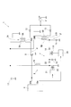
- FIG. 1 shows a schematic configuration diagram of an ignition device (Example 1).
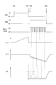
- Example 1 which shows the time chart for demonstrating operation
- Example 2 which shows the schematic block diagram of an ignition device.
- (A) is explanatory drawing of the state which reverse-biases the core which lets the magnetic flux which generate
- (B) shows explanatory drawing of the state which reversely biases the core which lets the magnetic flux which generate
- Example 2 which shows the magnetization characteristic figure explaining that energy increases by the reverse bias accompanying magnet use.
- (Example 3) which shows the schematic block diagram of an ignition device.
- the ignition device 1 is mounted on a spark ignition engine for running a vehicle, and ignites an air-fuel mixture in a combustion chamber at a predetermined ignition timing.
- An example of the engine is a direct injection engine capable of lean burn using gasoline as fuel, and a swirl flow control means for generating a swirl flow of an air-fuel mixture such as a tumble flow or a swirl flow in a cylinder. Prepare. Then, in an operating state where the gas flow rate in the cylinder is high and there is a possibility that spark discharge will blow out, such as lean burn, the ignition device 1 is controlled to perform continuous spark discharge in addition to main ignition.
- the ignition device 1 is a DI (Direct Ignition) type, and applies electric energy from two ignition coils including a first ignition coil 3A and a second ignition coil 3B to one ignition plug 2 of each cylinder. Is. Furthermore, the ignition device 1 includes a first ignition coil 3A, a second ignition coil 3A, and the like based on signals such as an ignition signal IGt and a discharge continuation signal IGw given from an electronic control unit (hereinafter referred to as ECU 4) that forms the center of engine control.
- ECU 4 electronice control unit
- the primary coil 5A, 5B of each 3B is energized and controlled.
- the ignition device 1 controls the spark discharge of the spark plug 2 by controlling the energization of the primary coils 5A and 5B to operate the electric energy generated in the secondary coils 6A and 6B of the ignition coil.
- the ECU 4 receives signals from various sensors that detect parameters (warm-up state, engine rotation speed, engine load, presence / absence of lean combustion, degree of swirling flow, etc.) indicating the operating state and control state of the engine. .
- the ECU 4 also includes an input circuit that processes an input signal, a CPU that performs control processing and arithmetic processing related to engine control based on the input signal, and various types of data stored and held such as data and programs necessary for engine control. And an output circuit for outputting signals necessary for engine control based on the processing results of the memory and CPU. Then, the ECU 4 generates and outputs an ignition signal IGt and a discharge continuation signal IGw corresponding to engine parameters acquired from various sensors.
- the ignition device 1 includes a spark plug 2, first and second ignition coils 3A and 3B, a first switching unit 8, a booster circuit 9, a second switching unit 10, and first to second ignition switches described below. 4 diodes 12 to 15 are provided.
- the spark plug 2 has a well-known structure, and a center electrode connected to the first end of the secondary coil 6A and the first end of the secondary coil 6B each having a first end and a second end, And a ground electrode that is grounded through an engine cylinder head or the like. A voltage is applied between the center electrode and the ground electrode by the electric energy generated in the secondary coils 6A and 6B, and a spark discharge is generated.
- the first and second ignition coils 3A and 3B have primary coils 5A and 5B and secondary coils 6A and 6B, respectively, and increase or decrease in the current (primary current) flowing through the primary coils 5A and 5B.
- This is a well-known structure for generating a current (secondary current) in the secondary coils 6A and 6B by electromagnetic induction.
- each of the primary coils 5A and 5B has a first end and a second end, and both of the first ends are connected to the plus electrode of the in-vehicle battery 17 and the second end is connected via various electronic elements.
- lines connecting the second ends of the primary coils 5A and 5B to the ground may be referred to as ground lines ⁇ and ⁇ , respectively).
- the first end is connected to the center electrode of the spark plug 2, and the second end is connected to the ground.
- the first switching unit 8 is provided on the ground line ⁇ and turns on / off the energization from the in-vehicle battery 17 to the primary coil 5A, and is connected to the primary coil 5A during a period when the ignition signal IGt is given from the ECU 4. Turn on the power.
- the ignition signal IGt is a signal for turning on the energization in the primary coil 5A, and more specifically, a signal for instructing a period in which magnetic energy is stored in the primary coil 5A.
- the first switching unit 8 is a power transistor, a MOS transistor, a thyristor, or the like.
- the first switching unit 8 when the first switching unit 8 is turned on during the period when the ignition signal IGt is given from the ECU 4, the voltage of the in-vehicle battery 17 is applied to the primary coil 5A, and a positive primary current is energized, and the primary coil 5A. Magnetic energy is stored in After that, when the first switching unit 8 is turned off, the magnetic energy stored in the primary coil 5A is converted into electric energy by electromagnetic induction, and a high voltage is generated in the secondary coil 6A and between the electrodes of the spark plug 2 A high voltage is applied and main ignition occurs.
- the booster circuit 9 boosts the voltage of the in-vehicle battery 17 and stores it as electric energy in the capacitor 18, and boosts and stores the voltage of the in-vehicle battery 17 during a period when the ignition signal IGt is given from the ECU 4.
- the booster circuit 9 includes a choke coil 19, a boosting switching unit 20, a boosting driver circuit 21, and a diode 22.
- the boosting switching unit 20 is, for example, a MOS transistor.
- one end of the choke coil 19 is connected to the plus electrode of the in-vehicle battery 17, and the energization state of the choke coil 19 is interrupted by the boosting switching unit 20. Further, the boosting driver circuit 21 supplies a control signal to the boosting switching unit 20 to turn on / off the boosting switching unit 20, and the choke coil 19 is operated by the on / off operation of the boosting switching unit 20. The stored magnetic energy is charged as electrical energy by the capacitor 18.
- the boosting driver circuit 21 is provided so as to repeatedly turn on / off the boosting switching unit 20 at a predetermined period during a period when the ignition signal IGt is given from the ECU 4.
- the diode 22 prevents the electric energy stored in the capacitor 18 from flowing back to the choke coil 19 side.
- the second switching unit 10 is generated by turning on / off the first switching unit 8 between the electrodes of the spark plug 2 by putting the electric energy stored in the booster circuit 9 into the primary coil 5B by the on operation. The current in the same direction as the spark discharge is superimposed and added, and the continuous spark discharge following the main ignition is continued. More specifically, the second switching unit 10 is turned on by a control signal supplied from the driver circuit 24 and is provided in the next energy input line ⁇ .
- the energy input line ⁇ is connected to the ground line ⁇ and is a line for supplying the electric energy of the booster circuit 9 from the second end (minus side) of the primary coil 5B.
- the driver circuit 24 repeatedly switches between high and low of the control signal during the period when the discharge continuation signal IGw is given from the ECU 4 and outputs the signal.
- the discharge continuation signal IGw is a signal for instructing a period during which the continuous spark discharge is continued. More specifically, the driver circuit 24 causes the second switching unit 10 to repeatedly turn on / off, and then from the booster circuit 9. This is a signal for instructing a period for supplying electric energy to the primary coil 5B.
- the second switching unit 10 repeatedly turns on / off to sequentially input the electric energy of the booster circuit 9 to the primary coil 5B, thereby continuing the continuous spark discharge. Is done.
- the second switching unit 10 is a power transistor, a MOS transistor, a thyristor, or the like.
- the first and second diodes 12 and 13 are provided between the center electrode of the spark plug 2 and the secondary coils 6A and 6B, respectively, so that the direction of the discharge current is the same in the main ignition and the continuous spark discharge. Limited. That is, the first and second diodes 12 and 13 have two discharge currents when the secondary current flows through the secondary coil 6 ⁇ / b> A by turning on / off the first switching unit 8 and two by turning on / off the second switching unit 10. It is provided so that the discharge current when the secondary current flows through the secondary coil 6B is in the same direction.
- the third diode 14 is provided on the negative side of the second switching unit 10 in the energy input line ⁇ , and prevents the backflow of current from the primary coil 5B to the booster circuit 9. Furthermore, the fourth diode 15 is provided on the ground side of the ground line ⁇ with respect to the connection point with the energy input line ⁇ , and operates as a free-wheeling diode when the second switching unit 10 is switched from on to off. That is, the fourth diode 15 causes the electromotive force generated in the primary coil 5B when the second switching unit 10 is turned off to the path from the primary coil 5B to the vehicle battery 17, ground, the fourth diode 15, and the primary coil 5B. Reflux.
- IGt represents the input state of the ignition signal IGt as high / low
- IGw represents the input state of the discharge continuation signal IGw as high / low
- On switch indicates ON / OFF of the second switching unit 10
- I 11” and I 12 are values of primary current flowing through the primary coils 5 A and 5 B, respectively
- I 2 is a discharge current. Represents a value.
- the first switching unit 8 When the ignition signal IGt switches from low to high (see time t01), during the period in which the ignition signal IGt is high, the first switching unit 8 remains on and a positive primary current flows through the primary coil 5A. Magnetic energy is stored. In addition, electric energy is stored in the booster circuit 9.
- the first switching unit 8 is turned off and the energized state of the primary coil 5A is cut off (see time t02).
- the magnetic energy stored in the primary coil 5A is converted into electric energy, a high voltage is generated in the secondary coil 6A, and main ignition is started in the spark plug 2.
- the discharge current is attenuated in a substantially triangular wave shape.
- the discharge continuation signal IGw switches from low to high before the discharge current reaches a predetermined lower threshold (the lower limit of the current value necessary for maintaining spark discharge) (see time t03).
- the second switching unit 10 When the discharge continuation signal IGw is switched from low to high, the second switching unit 10 is turned on / off, and the electric energy stored in the booster circuit 9 is sequentially input to the negative side of the primary coil 5B.
- a primary current flows from the coil 5 ⁇ / b> B toward the plus electrode of the in-vehicle battery 17. More specifically, each time the second switching unit 10 is turned on, a primary current from the primary coil 5B to the positive electrode of the in-vehicle battery 17 is added and increases toward the negative side (time t03 to t04). reference.).
- the secondary current is sequentially added to the secondary coil 6B, and the discharge current is maintained at a substantially constant value in the same direction as during main ignition. As a result, the spark discharge generated as the main ignition continues as the continuous spark discharge.
- the ignition device 1 applies electric energy from two first and second ignition coils 3A and 3B to one ignition plug 2, and includes the following first switching unit 8 and second switching unit. 10 is provided.
- the first switching unit 8 applies a voltage between the electrodes of the spark plug 2 by turning on / off energization from the in-vehicle battery 17 to the primary coil 5A.
- the second switching unit 10 generates electric energy stored in the booster circuit 9 into the primary coil 5B, and is generated between the electrodes of the spark plug 2 by turning on / off the first switching unit 8. Apply a voltage in the same direction.
- the first switching unit 8 is turned on / off to apply a voltage between the electrodes of the spark plug 2 to start main ignition, and during the started main ignition, the second switching unit 10 is repeatedly turned on / off.
- the electric energy of the booster circuit 9 is sequentially applying to the primary coil 5B, a voltage in the same direction is continuously applied between the electrodes of the spark plug 2, and the continuous spark discharge is continued in the main discharge.
- the second switching unit 10 is repeatedly turned on / off to repeat the primary coil.
- continuous spark discharge can be continued for an arbitrary period.
- the ON periods of the first and second switching units 8 and 10 do not overlap.
- the first and second ignition coils 3A and 3B are separately provided for main ignition and for continuous spark discharge, respectively, heat generation due to energization during main ignition and heat generation due to energization during continuous spark discharge are provided. Can be dispersed. For this reason, the ignition device 1 can be reduced in size. Further, by matching the time t02 for switching the ignition signal IGt from high to low with the time t03 for switching the discharge continuation signal IGw from low to high, the secondary current is increased to a level necessary for ignition earlier. Therefore, the ignitability can be further improved. Furthermore, depending on the operating state of the engine, it is possible to select whether to generate only the main ignition or to continue the continuous spark discharge in the main ignition. For this reason, the optimal ignition mode can be selected according to the operating state of the engine.
- the first ignition coil 3A preferably has a large turn ratio because it is necessary to apply a large voltage between the electrodes of the plug in order to generate main ignition first
- the second ignition coil 3B It is preferable to increase the inductance because of the need to maintain current. Therefore, by setting the specifications of the first and second ignition coils 3A and 3B in response to these requests, it is possible to enhance the effects of ensuring ignitability, maintaining stable discharge current, and suppressing consumption of the electrodes of the spark plug 2. .
- the second end of the primary coil 5B is connected to the ground via a fourth diode 15 that operates as a freewheeling diode, and the energy input line ⁇ is connected to a connection point between the primary coil 5B and the fourth diode 15.
- the ground diode ⁇ incorporates the fourth diode 15 that operates as a freewheeling diode on the ground side with respect to the connection point with the energy input line ⁇ .
- the electromotive force generated in the primary coil 5B when the second switching unit 10 is turned off can be recirculated from the primary coil 5B through the path of the in-vehicle battery 17, the ground, the return diode 15, and the primary coil 5B. For this reason, the continuous spark discharge can be stably continued by avoiding the instantaneous interruption of the secondary current.
- the ignition device 1 includes first and second magnets 26A and 26B having reverse bias polarities described below.
- the first magnet 26A is incorporated in a core 27A that passes a magnetic flux generated by energization of the primary coil 5A, and reverse biases the core 27A.
- the second magnet 26B is provided separately from the first magnet 26A and is incorporated in the core 27B through which the magnetic flux generated by energization of the primary coil 5B passes, thereby reversely biasing the core 27B.
- the core 27A is reverse-biased by the first magnet 26A, and the change width of the magnetic flux density B until the magnetic saturation point Bs is reached (see the change widths ⁇ B0 and ⁇ Ba in FIG. 5). .)
- the energy stored in the primary coil 5A can be increased.
- the core 27B is reverse-biased by the second magnet 26B, and the change width of the magnetic flux density B until reaching the magnetic saturation point Bs increases (change widths ⁇ B0 and ⁇ Bb in FIG. 5). (See.) Energy stored in the primary coil 5B can be increased.
- the first magnet 26A can be incorporated in the direction of strengthening the main ignition and with the strength of strengthening the main ignition
- the second magnet 26B is in the direction of enhancing the continuous spark discharge with the same polarity as the main ignition.
- it can be incorporated with the strength to enhance the continuous spark discharge.
- the performance of the first and second ignition coils 3A and 3B can be individually enhanced by the first and second magnets 26A and 26B, respectively.
- energy that can be stored in the primary coil 5A when the core 27A is not reverse-biased by the first magnet 26A and energy that can be stored in the primary coil 5B when the core 27B is not reverse-biased by the second magnet 26B.
- the first and second magnets 26A and 26B are incorporated in the cores 27A and 27B, respectively, in order to enhance the main ignition and the continuous spark discharge.
- the magnetization force Hca of the first magnet 26A is made larger than the magnetization force Hcb of the second magnet 26B.
- the energy stored in the primary coils 5A and 5B can be increased by the first and second magnets 26A and 26B, respectively, and the energy stored in the primary coil 5A is larger than the energy stored in the primary coil 5B. can do.
- Example 3 With reference to FIG. 6, the third embodiment will be described with a focus on differences from the first embodiment.
- the same reference numerals as those in the first embodiment denote the same functional objects.
- the first end of the primary coil 5B is connected to the ground.
- the potential ahead from the primary coil 5 ⁇ / b> B can be lowered as compared with the first embodiment with respect to the path of the return of electromotive force associated with the on / off of the second switching unit 10.
- the booster circuit 9 since the boosting width by the booster circuit 9 can be reduced, various elements used in the booster circuit 9 (capacitor 18, booster switching unit 20, diode 22, etc.) and the second switching unit used in the energy input line ⁇ . 10 having a low withstand voltage can be employed. As a result, it is possible to achieve cost reduction and physique reduction of the ignition device 1 and improvement in electric energy storage efficiency in the booster circuit 9.
- the first and second magnets 26A and 26B are incorporated in the cores 27A and 27B to enhance both the main ignition and the continuous spark discharge.
- the core 27B is not magnetically saturated.
- the incorporation of the second magnet 26B may be omitted to reduce the cost.
- the ignition device 1 of the present invention is used for a gasoline engine.
- the ignition property of fuel specifically, air-fuel mixture
- ethanol fuel can be used.
- an engine using a mixed fuel Even if it is used for an engine in which poor fuel may be used, the ignitability can be improved by continuous spark discharge.
- the ignition device 1 of the present invention is used for an engine capable of lean burn operation.
- ignitability is caused by continuous spark discharge. Since improvement can be achieved, the present invention is not limited to application to an engine capable of lean combustion, and may be used for an engine that does not perform lean combustion.
- the ignition device 1 of the present invention is used in a direct injection engine that directly injects fuel into the combustion chamber.
- port injection that injects fuel to the intake upstream side (inside the intake port) of the intake valve. It may be used for a formula engine.
- the ignition device 1 of the present invention is used for an engine that positively generates a swirl flow (such as a tumble flow or a swirl flow) of an air-fuel mixture in a cylinder.
- a swirl flow such as a tumble flow or a swirl flow
- the present invention is applied to the DI type ignition device 1, but a distributor type that distributes the secondary voltage to each spark plug 2 or a single cylinder engine that does not require the distribution of the secondary voltage (
- the present invention may be applied to the ignition device 1 of a motorcycle.
Landscapes
- Engineering & Computer Science (AREA)
- Chemical & Material Sciences (AREA)
- Combustion & Propulsion (AREA)
- Mechanical Engineering (AREA)
- General Engineering & Computer Science (AREA)
- Ignition Installations For Internal Combustion Engines (AREA)
Abstract
点火装置1によれば、第1スイッチング部8は、車載バッテリ17から1次コイル5Aへの通電をオン/オフすることで点火プラグ2の電極間に電圧を印加する。また、第2スイッチング部10は、昇圧回路9に蓄えた電気エネルギーを1次コイル5Bに投入することで、点火プラグ2の電極間に、第1スイッチング部8のオン/オフにより発生するのと同一方向の電圧を印加する。これにより、第1、第2スイッチング部8、10のオン/オフに係わる煩雑さを従来に比べて大きく低減することができる。
Description
本発明は、内燃機関に用いられる点火装置に関する。
点火装置として、1つの点火プラグに対して2つの点火コイルから電気エネルギーを与える内燃機関用の点火装置が公知である(例えば、特許文献1参照。)。この技術によれば、車載バッテリから一方の点火コイルの1次コイルへの通電をオン/オフする第1スイッチング部と、車載バッテリから他方の点火コイルの1次コイルへの通電をオン/オフする第2スイッチング部とを備える。そして、第1、第2スイッチング部のオン期間が重ならないように、いわゆるフルトランジスタに基づくオン/オフ動作を第1、第2スイッチング部に交互に繰り返させる。これにより、放電途切れのない安定した放電状態を維持することができるとされている。
しかし、特許文献1の技術によれば、第1、第2スイッチング部のオン期間が重なると、放電電流が急激に減少して火花放電が維持できなくなり、逆に、第1、第2スイッチング部のオフ期間が重なると、放電タイミングが重なり、放電電流が急激に増加して点火プラグにおいて電極に大きなダメージを与えてしまう。このため、第1、第2スイッチング部のオン/オフを、個々の部品ばらつきや内燃機関の運転状態の違いによる火花タイミングの変化等に追従するために、高精度に行う必要があるので、特許文献1の技術は、制御ロジックの構築が煩雑になり、実運転における演算負荷が大きいものと考えられる。
本発明は、上記問題点に鑑みてなされたものであり、その目的は、1つの点火プラグに対して2つの点火コイルから電気エネルギーを与える内燃機関用の点火装置において、2つのスイッチング部のオン/オフに係わる煩雑さを低減することにある。
内燃機関用の点火装置の第一の態様は、1つの点火プラグに対して第1点火コイルおよび第2点火コイルからなる2つの点火コイルから電気エネルギーを与える。また、点火装置は、次の第1、第2スイッチング部、および、昇圧回路を備える。
まず、第1スイッチング部は、車載バッテリから第1点火コイルの1次コイルへの通電をオン/オフすることで、点火プラグの電極間に電圧を印加して火花放電を開始させる。また、昇圧回路は、車載バッテリの電圧を昇圧して電気エネルギーを蓄える。さらに、第2スイッチング部は、昇圧回路に蓄えた電気エネルギーを第2点火コイルの1次コイルに投入することで、点火プラグの電極間に、第1スイッチング部のオン/オフにより発生した火花放電と同一方向の電流を重畳する。
まず、第1スイッチング部は、車載バッテリから第1点火コイルの1次コイルへの通電をオン/オフすることで、点火プラグの電極間に電圧を印加して火花放電を開始させる。また、昇圧回路は、車載バッテリの電圧を昇圧して電気エネルギーを蓄える。さらに、第2スイッチング部は、昇圧回路に蓄えた電気エネルギーを第2点火コイルの1次コイルに投入することで、点火プラグの電極間に、第1スイッチング部のオン/オフにより発生した火花放電と同一方向の電流を重畳する。
そして、第2スイッチング部により昇圧回路の電気エネルギーを第2点火コイルの1次コイルに投入することで、点火プラグの電極間に、第1スイッチング部のオン/オフにより発生した火花放電と同一方向の火花放電を継続させる。
これにより、まず、第1スイッチング部のオン/オフによるフルトランジスタ点火に基づく動作により点火プラグの電極間に火花放電を開始させることができる。その後、この火花放電が消える前に、第2スイッチング部のオン/オフを繰り返して昇圧回路の電気エネルギーを第2点火コイルの1次コイルに逐次投入することで、火花放電を同じ極性のまま任意の期間にわたり継続させることができる。
これにより、まず、第1スイッチング部のオン/オフによるフルトランジスタ点火に基づく動作により点火プラグの電極間に火花放電を開始させることができる。その後、この火花放電が消える前に、第2スイッチング部のオン/オフを繰り返して昇圧回路の電気エネルギーを第2点火コイルの1次コイルに逐次投入することで、火花放電を同じ極性のまま任意の期間にわたり継続させることができる。
このため、第1、第2スイッチング部のオン期間が重ならないように、かつ、第1、第2スイッチング部のオフ期間が重ならないように配慮する必要がなくなる。したがって、1つの点火プラグに対して第1点火コイルおよび第2点火コイルからなる2つの点火コイルから電気エネルギーを与える点火装置において、第1、第2スイッチング部のオン/オフに係わる煩雑さを低減することができる。
以下の説明では、第1スイッチング部のオン/オフにより生じる火花放電を主点火と呼び、第2スイッチング部のオン/オフにより継続させる火花放電、つまり、主点火に続く火花放電を継続火花放電と呼ぶ。
以下の説明では、第1スイッチング部のオン/オフにより生じる火花放電を主点火と呼び、第2スイッチング部のオン/オフにより継続させる火花放電、つまり、主点火に続く火花放電を継続火花放電と呼ぶ。
また、第1点火コイルおよび第2点火コイルからなる2つの点火コイルをそれぞれの機能に合わせて仕様を異ならせることで、着火性確保、放電電流の安定維持およびプラグ電極の消耗抑制の効果を高めることができる。
例えば、第1点火コイルは、最初に主点火を発生させるために大きな電圧をプラグの電極間に印加する必要性から、巻き数比を大きくするのが好ましく、第2点火コイルは、放電電流を維持する必要性から、インダクタンスを大きくするのが好ましい。したがって、これら要請に応じて第1および第2点火コイルそれぞれの仕様を設定することで、着火性確保、放電電流の安定維持およびプラグ電極の消耗抑制の効果を高めることができる。
例えば、第1点火コイルは、最初に主点火を発生させるために大きな電圧をプラグの電極間に印加する必要性から、巻き数比を大きくするのが好ましく、第2点火コイルは、放電電流を維持する必要性から、インダクタンスを大きくするのが好ましい。したがって、これら要請に応じて第1および第2点火コイルそれぞれの仕様を設定することで、着火性確保、放電電流の安定維持およびプラグ電極の消耗抑制の効果を高めることができる。
点火装置の第二の態様は、第2点火コイルの1次コイルは第1端および第2端を有し、第1端が車載バッテリのプラス電極に接続されるとともに、第2端が還流ダイオードを介してアースに接続されている。また、昇圧回路から第2点火コイルの1次コイルへ電気エネルギーを投入するエネルギー投入ラインは、第2点火コイルの1次コイルと還流ダイオードとの接続点に接続されている。
これにより、第2スイッチング部をオンからオフに切り替えたときに第2点火コイルの1次コイルに発生する起電力を緩和することができる。つまり、第2スイッチング部のオフ時に1次コイルにおいて発生する起電力を、1次コイルから順に車載バッテリ、アース、還流ダイオード、1次コイルの経路で還流することができる。このため、点火プラグにおいて急激な電流変化を伴わずに継続火花放電を安定して継続させることができる。
点火装置の第三の態様は、第2点火コイルの1次コイルは第1端および第2端を有し、第1端がアースに接続されるとともに、第2端が還流ダイオードを介してアースに接続されている。また、昇圧回路から第2点火コイルの1次コイルへ電気エネルギーを投入するエネルギー投入ラインは、第2点火コイルの1次コイルと還流ダイオードとの接続点に接続されている。
これにより、第2スイッチング部のオン/オフに伴う起電力の還流の経路に関し、1次コイルから向う先の電位を、第二の態様よりも下げることができる。このため、昇圧回路による昇圧幅を下げることができるので、昇圧回路に用いる各種素子、および、エネルギー投入ラインに用いる各種素子に、耐圧が低いものを採用することができる。この結果、点火装置のコスト低減および体格低減、ならびに、昇圧回路における電気エネルギーの蓄積効率の向上を達成することができる。
点火装置の第四の態様は、点火装置は、逆バイアス極性の磁石を備える。
すなわち、磁石は、第1点火コイルの1次コイルへの通電により発生する磁束を通す磁路に組み入れられ、磁路をなすコアを、逆バイアスする。
これにより、コアで磁気飽和が発生しにくくなり、1次コイルに蓄えることができるエネルギーを増やすことができるので、主点火を強化することができる。
すなわち、磁石は、第1点火コイルの1次コイルへの通電により発生する磁束を通す磁路に組み入れられ、磁路をなすコアを、逆バイアスする。
これにより、コアで磁気飽和が発生しにくくなり、1次コイルに蓄えることができるエネルギーを増やすことができるので、主点火を強化することができる。
点火装置の第五の態様は、点火装置は、上記磁石は第1磁石であり、逆バイアス極性の第2磁石を備える。
すなわち、第2磁石は、第1磁石とは別体として設けられるとともに、第2点火コイルの1次コイルへの通電により発生する磁束を通す磁路に組み入れられ、磁路をなすコアを逆バイアスする。
これにより、コアで磁気飽和が発生しにくくなり、1次コイルに蓄えることができるエネルギーを増やすことができるので、継続火花放電を強化することができる。
すなわち、第2磁石は、第1磁石とは別体として設けられるとともに、第2点火コイルの1次コイルへの通電により発生する磁束を通す磁路に組み入れられ、磁路をなすコアを逆バイアスする。
これにより、コアで磁気飽和が発生しにくくなり、1次コイルに蓄えることができるエネルギーを増やすことができるので、継続火花放電を強化することができる。
以下において、発明を実施するための形態を、実施例を用いて説明する。なお、実施例は具体的な一例を開示するものであり、本発明が実施例に限定されないことは言うまでもない。
〔実施例1の構成〕
図1を参照して実施例1の点火装置1を説明する。
点火装置1は、車両走行用の火花点火エンジンに搭載されるものであり、所定の点火時期に燃焼室内の混合気に点火するものである。なお、エンジンの一例は、ガソリンを燃料とする希薄燃焼(リーンバーン)が可能な直噴式エンジンであり、気筒内にタンブル流やスワール流等の混合気の旋回流を生じさせる旋回流コントロール手段を備える。そして、リーンバーンのように気筒内のガス流速が高く火花放電の吹き消え発生の可能性がある運転状態において、点火装置1は、主点火に加えて継続火花放電を行うように制御される。
図1を参照して実施例1の点火装置1を説明する。
点火装置1は、車両走行用の火花点火エンジンに搭載されるものであり、所定の点火時期に燃焼室内の混合気に点火するものである。なお、エンジンの一例は、ガソリンを燃料とする希薄燃焼(リーンバーン)が可能な直噴式エンジンであり、気筒内にタンブル流やスワール流等の混合気の旋回流を生じさせる旋回流コントロール手段を備える。そして、リーンバーンのように気筒内のガス流速が高く火花放電の吹き消え発生の可能性がある運転状態において、点火装置1は、主点火に加えて継続火花放電を行うように制御される。
また、点火装置1は、DI(ダイレクト・イグニッション)タイプであり、各気筒の1つの点火プラグ2に対して第1点火コイル3Aおよび第2点火コイル3Bからなる2つの点火コイルから電気エネルギーを与えるものである。
さらに、点火装置1は、エンジン制御の中枢を成す電子制御ユニット(以下、ECU4と呼ぶ。)から与えられる点火信号IGtや放電継続信号IGw等の信号に基づいて第1および第2点火コイル3A、3Bそれぞれの1次コイル5A、5Bを通電制御するものである。そして、点火装置1は、1次コイル5A、5Bを通電制御することで点火コイルのそれぞれの2次コイル6A、6Bに生じる電気エネルギーを操作して、点火プラグ2の火花放電を制御する。
さらに、点火装置1は、エンジン制御の中枢を成す電子制御ユニット(以下、ECU4と呼ぶ。)から与えられる点火信号IGtや放電継続信号IGw等の信号に基づいて第1および第2点火コイル3A、3Bそれぞれの1次コイル5A、5Bを通電制御するものである。そして、点火装置1は、1次コイル5A、5Bを通電制御することで点火コイルのそれぞれの2次コイル6A、6Bに生じる電気エネルギーを操作して、点火プラグ2の火花放電を制御する。
ここで、ECU4は、エンジンの運転状態や制御状態を示すパラメータ(暖機状態、エンジン回転速度、エンジン負荷、希薄燃焼の有無、旋回流の程度等)を検出する各種センサから信号が入力される。また、ECU4は、入力された信号を処理する入力回路、入力された信号に基づき、エンジン制御に関する制御処理や演算処理を行うCPU、エンジン制御に必要なデータやプログラム等を記憶して保持する各種のメモリ、CPUの処理結果に基づき、エンジン制御に必要な信号を出力する出力回路等を備えて構成される。そして、ECU4は、各種センサから取得したエンジンパラメータに応じた点火信号IGtおよび放電継続信号IGwを生成して出力する。
実施例1の点火装置1は、以下に説明する、点火プラグ2、第1および第2点火コイル3A、3B、第1スイッチング部8、昇圧回路9、第2スイッチング部10、および第1~第4ダイオード12~15を備える。
まず、点火プラグ2は、周知構造を有するものであり、それぞれ第1端および第2端を有する2次コイル6Aの第1端および2次コイル6Bの第1端に接続される中心電極と、エンジンのシリンダヘッド等を介してアース接地される接地電極とを備える。そして、2次コイル6A、6Bに生じる電気エネルギーにより中心電極と接地電極との間に電圧が印加されて火花放電が発生する。
まず、点火プラグ2は、周知構造を有するものであり、それぞれ第1端および第2端を有する2次コイル6Aの第1端および2次コイル6Bの第1端に接続される中心電極と、エンジンのシリンダヘッド等を介してアース接地される接地電極とを備える。そして、2次コイル6A、6Bに生じる電気エネルギーにより中心電極と接地電極との間に電圧が印加されて火花放電が発生する。
第1および第2点火コイル3A、3Bは、それぞれ、1次コイル5A、5Bと2次コイル6A、6Bとを有し、1次コイル5A、5Bを流れる電流(1次電流)の増減に応じて電磁誘導により2次コイル6A、6Bに電流(2次電流)を発生させる周知構造である。ここで、1次コイル5A、5Bはそれぞれ第1端および第2端を有し、両方とも、第1端が車載バッテリ17のプラス電極に接続され、第2端が各種電子素子等を介してアースに接続されている(以下、1次コイル5A、5Bそれぞれの第2端をアースに接続するラインを、それぞれ、接地ラインα、βと呼ぶことがある。)。また、それぞれ第1端および第2端を有する2次コイル6A、6Bは、両方とも、第1端が点火プラグ2の中心電極に接続され、第2端がアースに接続されている。
第1スイッチング部8は、接地ラインαに設けられ、車載バッテリ17から1次コイル5Aへの通電をオン/オフするものであり、ECU4から点火信号IGtが与えられる期間に1次コイル5Aへの通電をオンする。ここで、点火信号IGtは、1次コイル5Aにおける通電をオンするための信号であり、より具体的には、1次コイル5Aに磁気エネルギーを蓄えさせる期間を指令する信号である。なお、第1スイッチング部8は、パワートランジスタ、MOS型トランジスタ、サイリスタ等である。
そして、ECU4から点火信号IGtが与えられる期間に第1スイッチング部8がオンすることで、1次コイル5Aに車載バッテリ17の電圧が印加されてプラスの1次電流が通電され、1次コイル5Aに磁気エネルギーが蓄えられる。その後、第1スイッチング部8のオフにより、電磁誘導によって、1次コイル5Aに蓄えられた磁気エネルギーが電気エネルギーに変換されて2次コイル6Aに高電圧が発生するとともに点火プラグ2の電極間に高電圧が印加され、主点火が生じる。
昇圧回路9は、車載バッテリ17の電圧を昇圧し、電気エネルギーとしてコンデンサ18に蓄えるものであり、ECU4から点火信号IGtが与えられる期間において車載バッテリ17の電圧を昇圧して蓄える。また、昇圧回路9は、コンデンサ18以外に、チョークコイル19、昇圧用スイッチング部20、昇圧用ドライバ回路21およびダイオード22を備えて構成される。なお、昇圧用スイッチング部20は、例えば、MOS型トランジスタである。
ここで、チョークコイル19は一端が車載バッテリ17のプラス電極に接続され、昇圧用スイッチング部20によりチョークコイル19の通電状態が断続される。また、昇圧用ドライバ回路21は、昇圧用スイッチング部20に制御信号を与えて昇圧用スイッチング部20をオン/オフさせるものであり、昇圧用スイッチング部20のオン/オフ動作により、チョークコイル19で蓄えた磁気エネルギーはコンデンサ18で電気エネルギーとして充電される。
なお、昇圧用ドライバ回路21は、ECU4から点火信号IGtが与えられる期間において昇圧用スイッチング部20を所定周期で繰り返してオン/オフするように設けられている。
また、ダイオード22は、コンデンサ18に蓄えた電気エネルギーがチョークコイル19側へ逆流するのを防ぐものである。
また、ダイオード22は、コンデンサ18に蓄えた電気エネルギーがチョークコイル19側へ逆流するのを防ぐものである。
第2スイッチング部10は、オン動作により、昇圧回路9に蓄えた電気エネルギーを1次コイル5Bに投入することで、点火プラグ2の電極間に、第1スイッチング部8のオン/オフにより発生した火花放電と同一方向の電流を重畳加算し、主点火に続く継続火花放電を継続させる。
より具体的に、第2スイッチング部10は、ドライバ回路24から与えられる制御信号によりオンするものであり、次のエネルギー投入ラインγに設けられている。
より具体的に、第2スイッチング部10は、ドライバ回路24から与えられる制御信号によりオンするものであり、次のエネルギー投入ラインγに設けられている。
すなわち、エネルギー投入ラインγは、接地ラインβに接続され、昇圧回路9の電気エネルギーを1次コイル5Bの第2端(マイナス側)から投入するラインである。また、ドライバ回路24は、ECU4から放電継続信号IGwが与えられる期間において、制御信号のハイ/ローを繰り返し切り替えて出力するものである。ここで、放電継続信号IGwは、継続火花放電を継続する期間を指令する信号であり、より具体的には、ドライバ回路24により第2スイッチング部10にオン/オフを繰り返させて昇圧回路9から1次コイル5Bに電気エネルギーを投入する期間を指令する信号である。
そして、第2スイッチング部10は、ECU4から放電継続信号IGwが与えられる間、オン/オフを繰り返して昇圧回路9の電気エネルギーを1次コイル5Bに逐次投入し、これにより、継続火花放電が継続される。
なお、第2スイッチング部10は、パワートランジスタ、MOS型トランジスタ、サイリスタ等である。
なお、第2スイッチング部10は、パワートランジスタ、MOS型トランジスタ、サイリスタ等である。
第1、第2ダイオード12、13は、それぞれ、点火プラグ2の中心電極と2次コイル6A、6Bとの間に設けられ、主点火と継続火花放電とで放電電流の方向を同一の方向にして限定する。つまり、第1、第2ダイオード12、13は、第1スイッチング部8のオン/オフにより2次コイル6Aに2次電流が流れるときの放電電流と、第2スイッチング部10のオン/オフにより2次コイル6Bに2次電流が流れるときの放電電流とが同一の方向となるように設けられる。
また、第3ダイオード14は、エネルギー投入ラインγにおいて第2スイッチング部10のマイナス側に設けられ、1次コイル5Bから昇圧回路9への電流の逆流を阻止するものである。
さらに、第4ダイオード15は、接地ラインβにおいてエネルギー投入ラインγとの接続点よりもアース側に設けられ、第2スイッチング部10をオンからオフに切り替えたときに還流ダイオードとして動作する。つまり、第4ダイオード15は、第2スイッチング部10のオフ時に1次コイル5Bにおいて発生する起電力を、1次コイル5Bから車載バッテリ17、アース、第4ダイオード15、1次コイル5Bの経路で還流する。
さらに、第4ダイオード15は、接地ラインβにおいてエネルギー投入ラインγとの接続点よりもアース側に設けられ、第2スイッチング部10をオンからオフに切り替えたときに還流ダイオードとして動作する。つまり、第4ダイオード15は、第2スイッチング部10のオフ時に1次コイル5Bにおいて発生する起電力を、1次コイル5Bから車載バッテリ17、アース、第4ダイオード15、1次コイル5Bの経路で還流する。
次に、図2を参照して点火装置1の動作を説明する。
なお、図2において、「IGt」は点火信号IGtの入力状態をハイ/ローで表すものであり、「IGw」は放電継続信号IGwの入力状態をハイ/ローで表すものである。また、「投入スイッチ」は、第2スイッチング部10のオン/オフを表し、「I11」、「I12」はそれぞれ1次コイル5A、5Bに流れる1次電流の値、「I2」は放電電流の値を表す。
なお、図2において、「IGt」は点火信号IGtの入力状態をハイ/ローで表すものであり、「IGw」は放電継続信号IGwの入力状態をハイ/ローで表すものである。また、「投入スイッチ」は、第2スイッチング部10のオン/オフを表し、「I11」、「I12」はそれぞれ1次コイル5A、5Bに流れる1次電流の値、「I2」は放電電流の値を表す。
点火信号IGtがローからハイへ切り替わると(時間t01参照。)、点火信号IGtがハイの期間において、第1スイッチング部8がオン状態を維持して1次コイル5Aにプラスの1次電流が流れて磁気エネルギーが蓄えられる。また、昇圧回路9に電気エネルギーが蓄えられる。
やがて、点火信号IGtがハイからローへ切り替わると、第1スイッチング部8がオフされ、1次コイル5Aの通電状態が遮断される(時間t02参照。)。これにより、1次コイル5Aに蓄えられた磁気エネルギーが電気エネルギーに変換されて2次コイル6Aに高電圧が発生し、点火プラグ2において主点火が開始される。
点火プラグ2において主点火が開始された後、放電電流は略三角波形状で減衰する。そして、放電電流が所定の下限閾値(火花放電を維持するために必要な電流値の下限)に到達する前に、放電継続信号IGwがローからハイへ切り替わる(時間t03参照。)。
点火プラグ2において主点火が開始された後、放電電流は略三角波形状で減衰する。そして、放電電流が所定の下限閾値(火花放電を維持するために必要な電流値の下限)に到達する前に、放電継続信号IGwがローからハイへ切り替わる(時間t03参照。)。
放電継続信号IGwがローからハイへ切り替わると、第2スイッチング部10がオン/オフされて、昇圧回路9に蓄えられていた電気エネルギーが、1次コイル5Bのマイナス側に順次投入され、1次コイル5Bから車載バッテリ17のプラス電極に向かって1次電流が流れる。より具体的には、第2スイッチング部10がオンされる毎に、1次コイル5Bから車載バッテリ17のプラス電極に向かう1次電流が追加されてマイナス側に増加していく(時間t03~t04参照。)。
そして、1次電流が1次コイル5Bに追加される毎に、2次コイル6Bに2次電流が順次追加され、放電電流は主点火時と同じ方向に略一定の値に維持される。この結果、主点火として生じた火花放電が継続火花放電として継続する。
そして、1次電流が1次コイル5Bに追加される毎に、2次コイル6Bに2次電流が順次追加され、放電電流は主点火時と同じ方向に略一定の値に維持される。この結果、主点火として生じた火花放電が継続火花放電として継続する。
〔実施例1の効果〕
実施例1の点火装置1は、1つの点火プラグ2に対して2つの第1および第2点火コイル3A、3Bから電気エネルギーを与えるものであり、次の第1スイッチング部8および第2スイッチング部10を備える。まず、第1スイッチング部8は、車載バッテリ17から1次コイル5Aへの通電をオン/オフすることで点火プラグ2の電極間に電圧を印加する。また、第2スイッチング部10は、昇圧回路9に蓄えた電気エネルギーを1次コイル5Bに投入することで、点火プラグ2の電極間に、第1スイッチング部8のオン/オフにより発生するのと同一方向の電圧を印加する。
実施例1の点火装置1は、1つの点火プラグ2に対して2つの第1および第2点火コイル3A、3Bから電気エネルギーを与えるものであり、次の第1スイッチング部8および第2スイッチング部10を備える。まず、第1スイッチング部8は、車載バッテリ17から1次コイル5Aへの通電をオン/オフすることで点火プラグ2の電極間に電圧を印加する。また、第2スイッチング部10は、昇圧回路9に蓄えた電気エネルギーを1次コイル5Bに投入することで、点火プラグ2の電極間に、第1スイッチング部8のオン/オフにより発生するのと同一方向の電圧を印加する。
そして、第1スイッチング部8のオン/オフにより点火プラグ2の電極間に電圧を印加して主点火を開始させるとともに、開始した主点火中に、第2スイッチング部10のオン/オフを繰り返して昇圧回路9の電気エネルギーを1次コイル5Bに逐次投入することで、点火プラグ2の電極間に同一方向の電圧を印加し続け、主放電に継続火花放電を継続させる。
これにより、第1スイッチング部8のオン/オフによるフルトランジスタ点火に基づく動作により主点火を開始させた後、主点火が消える前に、第2スイッチング部10のオン/オフを繰り返して1次コイル5Bに電気エネルギーを投入することで、継続火花放電を任意の期間にわたり継続させることができる。
このため、1つの点火プラグ2に対して2つの第1および第2点火コイル3A、3Bから電気エネルギーを与える点火装置1において、第1、第2スイッチング部8、10のオン期間が重ならないように、かつ、第1、第2スイッチング部8、10のオフ期間が重ならないように配慮する必要がなくなる。したがって、第1、第2スイッチング部8、10のオン/オフに係わる煩雑さを従来に比べて大きく低減することができる。
また、第1および第2点火コイル3A、3Bをそれぞれ主点火用、継続火花放電用として個別に設けたので、主点火時の通電に伴う発熱と、継続火花放電時の通電に伴う発熱とを分散させることができる。このため、点火装置1を小型化することができる。
また、点火信号IGtをハイからローに切り替える時間t02と、放電継続信号IGwをローからハイに切り替える時間t03とを一致させることで、より早期に、着火に必要なレベルまで2次電流を高めることができるので、着火性を更に高めることができる。
さらに、エンジンの運転状態に応じて、主点火のみを発生させるのか、または、主点火に継続火花放電を継続させるのかを選択することができる。このため、エンジンの運転状態に応じて、最適な点火の態様を選択することができる。
また、点火信号IGtをハイからローに切り替える時間t02と、放電継続信号IGwをローからハイに切り替える時間t03とを一致させることで、より早期に、着火に必要なレベルまで2次電流を高めることができるので、着火性を更に高めることができる。
さらに、エンジンの運転状態に応じて、主点火のみを発生させるのか、または、主点火に継続火花放電を継続させるのかを選択することができる。このため、エンジンの運転状態に応じて、最適な点火の態様を選択することができる。
また、第1および第2点火コイル3A、3Bをそれぞれの機能に合わせて仕様を異ならせることで、着火性確保、放電電流の安定維持およびプラグ電極の消耗抑制の効果を高めることができる。
例えば、第1点火コイル3Aは、最初に主点火を発生させるために大きな電圧をプラグの電極間に印加する必要性から、巻き数比を大きくするのが好ましく、第2点火コイル3Bは、放電電流を維持する必要性から、インダクタンスを大きくするのが好ましい。
したがって、これら要請に応じて第1および第2点火コイル3A、3Bの仕様を設定することで、着火性確保、放電電流の安定維持および点火プラグ2の電極の消耗抑制の効果を高めることができる。
例えば、第1点火コイル3Aは、最初に主点火を発生させるために大きな電圧をプラグの電極間に印加する必要性から、巻き数比を大きくするのが好ましく、第2点火コイル3Bは、放電電流を維持する必要性から、インダクタンスを大きくするのが好ましい。
したがって、これら要請に応じて第1および第2点火コイル3A、3Bの仕様を設定することで、着火性確保、放電電流の安定維持および点火プラグ2の電極の消耗抑制の効果を高めることができる。
また、1次コイル5Bの第2端は、還流ダイオードとして動作する第4ダイオード15を介してアースに接続され、エネルギー投入ラインγは、1次コイル5Bと第4ダイオード15との接続点に接続されている。つまり、接地ラインβには、エネルギー投入ラインγとの接続点よりもアース側に、還流ダイオードとして動作する第4ダイオード15が組み入れられている。
これにより、第2スイッチング部10をオンからオフに切り替えたときに1次コイル5Bに発生する起電力を緩和することができる。つまり、第2スイッチング部10のオフ時に1次コイル5Bにおいて発生する起電力を、1次コイル5Bから車載バッテリ17、アース、還流ダイオード15、1次コイル5Bの経路で還流することができる。このため、2次電流の瞬断を回避して継続火花放電を安定的に継続させることができる。
これにより、第2スイッチング部10をオンからオフに切り替えたときに1次コイル5Bに発生する起電力を緩和することができる。つまり、第2スイッチング部10のオフ時に1次コイル5Bにおいて発生する起電力を、1次コイル5Bから車載バッテリ17、アース、還流ダイオード15、1次コイル5Bの経路で還流することができる。このため、2次電流の瞬断を回避して継続火花放電を安定的に継続させることができる。
〔実施例2〕
図3、図4(a)および図4(b)を参照して実施例2を実施例1と異なる点を中心に説明する。なお、実施例2において上記実施例1と同一符号は、同一機能物を示すものである。
実施例2の点火装置1は、以下に説明する逆バイアス極性の第1および第2磁石26A、26Bを備える。まず、第1磁石26Aは、1次コイル5Aへの通電により発生する磁束を通すコア27Aに組み入れられ、コア27Aを逆バイアスする。また、第2磁石26Bは、第1磁石26Aとは別体として設けられるとともに、1次コイル5Bへの通電により発生する磁束を通すコア27Bに組み入れられ、コア27Bを逆バイアスする。
図3、図4(a)および図4(b)を参照して実施例2を実施例1と異なる点を中心に説明する。なお、実施例2において上記実施例1と同一符号は、同一機能物を示すものである。
実施例2の点火装置1は、以下に説明する逆バイアス極性の第1および第2磁石26A、26Bを備える。まず、第1磁石26Aは、1次コイル5Aへの通電により発生する磁束を通すコア27Aに組み入れられ、コア27Aを逆バイアスする。また、第2磁石26Bは、第1磁石26Aとは別体として設けられるとともに、1次コイル5Bへの通電により発生する磁束を通すコア27Bに組み入れられ、コア27Bを逆バイアスする。
つまり、主点火を生じさせる時に、コア27Aは、第1磁石26Aにより逆バイアスされ、磁気飽和点Bsに達するまでの磁束密度Bの変化幅が大きくなるので(図5の変化幅ΔB0、ΔBa参照。)、1次コイル5Aに蓄えるエネルギーを増やすことができる。また、継続火花放電を継続する時に、コア27Bは、第2磁石26Bにより逆バイアスされ、磁気飽和点Bsに達するまでの磁束密度Bの変化幅が大きくなるので(図5の変化幅ΔB0、ΔBb参照。)、1次コイル5Bに蓄えるエネルギーを増やすことができる。
これにより第1磁石26Aについては主点火を強化する方向に、かつ、主点火を強化する強さで組み入れることができ、第2磁石26Bについては主点火と同じ極性で継続火花放電を強化する方向に、かつ、継続火花放電を強化する強さで組み入れることができる。この結果、第1および第2点火コイル3A、3Bの性能をそれぞれ第1および第2磁石26A、26Bよって個別に高めることができる。
例えば、コア27Aを第1磁石26Aで逆バイアスしない場合に1次コイル5Aに蓄えることができるエネルギー、および、コア27Bを第2磁石26Bで逆バイアスしない場合に1次コイル5Bに蓄えることができるエネルギーは、図5において縦軸、磁化曲線Mc、および、B=磁気飽和点Bsの横線の3つにより囲まれた領域αの面積に相当する。
これに対し、主点火および継続火花放電の強化のため、コア27A、27Bのそれぞれに第1および第2磁石26A、26Bを組み入れる場合を考える。ここで、継続火花放電の継続よりも主点火の発生に、より大きなエネルギーが必要であることから、第1磁石26Aの磁化力Hcaを第2磁石26Bの磁化力Hcbよりも大きくする。
これにより、コア27Aを第1磁石26Aで逆バイアスした場合に、1次コイル5Aに蓄えることができるエネルギーは、図5においてH=-Hcaの縦線、磁化曲線Mc、および、B=磁気飽和点Bsの横線の3つにより囲まれた領域βの面積に相当するものとなる。また、コア27Bを第2磁石26Bで逆バイアスする場合に、1次コイル5Bに蓄えることができるエネルギーは、図5においてH=-Hcbの縦線、磁化曲線Mc、および、B=磁気飽和点Bsの横線の3つにより囲まれた領域γの面積に相当するものとなる。
以上により、1次コイル5A、5Bに蓄えるエネルギーをそれぞれ第1および第2磁石26A、26Bにより高めることができ、さらに、1次コイル5Aに蓄えるエネルギーを、1次コイル5Bに蓄えるエネルギーよりも大きくすることができる。
〔実施例3〕
図6を参照して実施例3を実施例1と異なる点を中心に説明する。なお、実施例3において上記実施例1と同一符号は、同一機能物を示すものである。
実施例3の点火装置1によれば、図6に示すように、1次コイル5Bの第1端がアースに接続されている。
これにより、第2スイッチング部10のオン/オフに伴う起電力の還流の経路に関し、1次コイル5Bから向う先の電位を実施例1に比べて下げることができる。このため、昇圧回路9による昇圧幅を下げることができるので、昇圧回路9に用いる各種素子(コンデンサ18、昇圧用スイッチング部20およびダイオード22等)、ならびに、エネルギー投入ラインγに用いる第2スイッチング部10に、耐圧が低いものを採用することができる。この結果、点火装置1のコスト低減および体格低減、ならびに、昇圧回路9における電気エネルギーの蓄積効率の向上を達成することができる。
図6を参照して実施例3を実施例1と異なる点を中心に説明する。なお、実施例3において上記実施例1と同一符号は、同一機能物を示すものである。
実施例3の点火装置1によれば、図6に示すように、1次コイル5Bの第1端がアースに接続されている。
これにより、第2スイッチング部10のオン/オフに伴う起電力の還流の経路に関し、1次コイル5Bから向う先の電位を実施例1に比べて下げることができる。このため、昇圧回路9による昇圧幅を下げることができるので、昇圧回路9に用いる各種素子(コンデンサ18、昇圧用スイッチング部20およびダイオード22等)、ならびに、エネルギー投入ラインγに用いる第2スイッチング部10に、耐圧が低いものを採用することができる。この結果、点火装置1のコスト低減および体格低減、ならびに、昇圧回路9における電気エネルギーの蓄積効率の向上を達成することができる。
〔変形例〕
上記の実施例では、第1および第2磁石26A、26Bをコア27A、27Bのそれぞれに組み入れて主点火、継続火花放電の両方を強化していたが、例えば、コア27Bが磁気飽和しないように1次コイル5Bへの通電量を制限することで、第2磁石26Bの組み入れを省略してコストダウンしてもよい。
上記の実施例では、第1および第2磁石26A、26Bをコア27A、27Bのそれぞれに組み入れて主点火、継続火花放電の両方を強化していたが、例えば、コア27Bが磁気飽和しないように1次コイル5Bへの通電量を制限することで、第2磁石26Bの組み入れを省略してコストダウンしてもよい。
上記の実施例では、ガソリンエンジンに本発明の点火装置1を用いる例を示したが、継続火花放電によって燃料(具体的には混合気)の着火性の向上を図ることができるため、エタノール燃料や混合燃料を用いるエンジンに適用してもよい。また、粗悪燃料が用いられる可能性のあるエンジンに用いても継続火花放電により着火性の向上を図ることができる。
上記の実施例では、希薄燃焼(リーンバーン)運転が可能なエンジンに本発明の点火装置1を用いる例を示したが、希薄燃焼とは異なる燃焼状態であっても継続火花放電によって着火性の向上を図ることができるため、希薄燃焼可能なエンジンへの適用に限定するものではなく、希薄燃焼を行わないエンジンに用いてもよい。
上記の実施例では、燃焼室に直接燃料を噴射する直噴式エンジンに本発明の点火装置1を用いる例を示したが、吸気バルブの吸気上流側(吸気ポート内)に燃料を噴射するポート噴射式のエンジンに用いてもよい。
上記の実施例では、混合気の旋回流(タンブル流やスワール流等)を気筒内にて積極的に生じさせるエンジンに本発明の点火装置1を用いる例を開示したが、旋回流コントロール手段(タンブル流コントロールバルブやスワール流コントロールバルブ等)を有しないエンジンに用いてもよい。
上記の実施例では、DIタイプの点火装置1に本発明を適用したが、2次電圧を各点火プラグ2に分配供給するディストリビュータタイプや、2次電圧の分配の必要性のない単気筒エンジン(例えば、自動二輪車等)の点火装置1に本発明を適用してもよい。
1 点火装置
2 点火プラグ
3A、3B 第1および第2点火コイル
5A、5B 1次コイル
8 第1スイッチング部
9 昇圧回路
10 第2スイッチング部
17 車載バッテリ
2 点火プラグ
3A、3B 第1および第2点火コイル
5A、5B 1次コイル
8 第1スイッチング部
9 昇圧回路
10 第2スイッチング部
17 車載バッテリ
Claims (6)
- 1つの点火プラグ(2)に対して第1点火コイル(3A)および第2点火コイル(3B)からなる2つの点火コイルから電気エネルギーを与える内燃機関用の点火装置(1)において、
車載バッテリ(17)から第1点火コイル(3A)の1次コイル(5A)への通電をオン/オフすることで、前記点火プラグ(2)の電極間に電圧を印加して火花放電を開始させる第1スイッチング部(8)と、
前記車載バッテリ(17)の電圧を昇圧して電気エネルギーを蓄える昇圧回路(9)と、
この昇圧回路(9)に蓄えた電気エネルギーを第2点火コイル(3B)の1次コイル(5B)に投入することで、前記点火プラグ(2)の電極間に、前記第1スイッチング部(8)のオン/オフにより発生した火花放電と同一方向の電流を重畳する第2スイッチング部(10)とを備え、
前記第2スイッチング部(10)により前記昇圧回路(9)の電気エネルギーを前記第2点火コイル(3B)の1次コイル(5B)に投入することで、前記点火プラグ(2)の電極間に、前記第1スイッチング部(8)のオン/オフにより発生した火花放電と同一方向の火花放電を継続させることを特徴とする点火装置(1)。 - 請求項1に記載の点火装置(1)において、
前記第2点火コイル(3B)の1次コイル(5B)は第1端および第2端を有し、第1端が前記車載バッテリ(17)のプラス電極に接続されるとともに、第2端が還流ダイオード(15)を介してアースに接続され、
前記昇圧回路(9)から前記第2点火コイル(3B)の1次コイル(5B)へ電気エネルギーを投入するエネルギー投入ライン(γ)は、前記第2点火コイル(3B)の1次コイル(5B)と前記還流ダイオード(15)との接続点に接続されていることを特徴とする点火装置(1)。 - 請求項1に記載の点火装置(1)において、
前記第2点火コイル(3B)の1次コイル(5B)は第1端および第2端を有し、第1端がアースに接続されるとともに、第2端が還流ダイオード(15)を介してアースに接続され、
前記昇圧回路(9)から前記第2点火コイル(3B)の1次コイル(5B)へ電気エネルギーを投入するエネルギー投入ライン(γ)は、前記第2点火コイル(3B)の1次コイル(5B)と前記還流ダイオード(15)との接続点に接続されていることを特徴とする点火装置(1)。 - 請求項1ないし請求項3の内のいずれか1つに記載の点火装置(1)において、
前記第1点火コイル(3A)の1次コイル(5A)への通電により発生する磁束を通す磁路(27A)に組み入れられる逆バイアス極性の磁石(26A)を備えることを特徴とする点火装置(1)。 - 請求項4に記載の点火装置(1)において、
前記磁石(26A)は第1磁石であり、
前記第1磁石(26A)とは別体として設けられるとともに、前記第2点火コイル(3B)の1次コイル(5B)への通電により発生する磁束を通す磁路(27B)に組み入れられる逆バイアス極性の第2磁石(26B)を備えることを特徴とする点火装置(1)。 - 請求項1ないし請求項5の内のいずれか1つに記載の点火装置(1)において、
前記第2点火コイル(3B)の1次コイル(5B)の巻き数比は、前記第1点火コイル(3A)の1次コイル(5A)の巻き数比よりも小さいことを特徴とする点火装置(1)。
Priority Applications (3)
| Application Number | Priority Date | Filing Date | Title |
|---|---|---|---|
| US15/302,552 US10041463B2 (en) | 2014-04-10 | 2015-04-09 | Ignition device |
| DE112015001714.3T DE112015001714B4 (de) | 2014-04-10 | 2015-04-09 | Zündvorrichtung |
| CN201580018922.8A CN106164469B (zh) | 2014-04-10 | 2015-04-09 | 点火装置 |
Applications Claiming Priority (6)
| Application Number | Priority Date | Filing Date | Title |
|---|---|---|---|
| JP2014-080625 | 2014-04-10 | ||
| JP2014080625 | 2014-04-10 | ||
| JP2014176988 | 2014-09-01 | ||
| JP2014-176988 | 2014-09-01 | ||
| JP2015030160A JP6520189B2 (ja) | 2014-04-10 | 2015-02-19 | 点火装置 |
| JP2015-030160 | 2015-02-19 |
Publications (1)
| Publication Number | Publication Date |
|---|---|
| WO2015156342A1 true WO2015156342A1 (ja) | 2015-10-15 |
Family
ID=54287914
Family Applications (1)
| Application Number | Title | Priority Date | Filing Date |
|---|---|---|---|
| PCT/JP2015/061058 Ceased WO2015156342A1 (ja) | 2014-04-10 | 2015-04-09 | 点火装置 |
Country Status (1)
| Country | Link |
|---|---|
| WO (1) | WO2015156342A1 (ja) |
Cited By (2)
| Publication number | Priority date | Publication date | Assignee | Title |
|---|---|---|---|---|
| JP2020139445A (ja) * | 2019-02-27 | 2020-09-03 | 株式会社デンソー | 内燃機関用点火装置 |
| EP4621213A1 (en) * | 2024-03-22 | 2025-09-24 | Diamond&Zebra Electric Mfg. Co., Ltd. | Dual ignition coil for a spark ignited internal combustion engine |
Citations (3)
| Publication number | Priority date | Publication date | Assignee | Title |
|---|---|---|---|---|
| JP2000170632A (ja) * | 1998-12-07 | 2000-06-20 | Ngk Spark Plug Co Ltd | 点火装置 |
| JP2000310175A (ja) * | 1999-04-27 | 2000-11-07 | Hanshin Electric Co Ltd | 内燃機関用点火装置 |
| JP2012041912A (ja) * | 2010-07-22 | 2012-03-01 | Diamond Electric Mfg Co Ltd | 内燃機関用制御システム |
-
2015
- 2015-04-09 WO PCT/JP2015/061058 patent/WO2015156342A1/ja not_active Ceased
Patent Citations (3)
| Publication number | Priority date | Publication date | Assignee | Title |
|---|---|---|---|---|
| JP2000170632A (ja) * | 1998-12-07 | 2000-06-20 | Ngk Spark Plug Co Ltd | 点火装置 |
| JP2000310175A (ja) * | 1999-04-27 | 2000-11-07 | Hanshin Electric Co Ltd | 内燃機関用点火装置 |
| JP2012041912A (ja) * | 2010-07-22 | 2012-03-01 | Diamond Electric Mfg Co Ltd | 内燃機関用制御システム |
Cited By (6)
| Publication number | Priority date | Publication date | Assignee | Title |
|---|---|---|---|---|
| JP2020139445A (ja) * | 2019-02-27 | 2020-09-03 | 株式会社デンソー | 内燃機関用点火装置 |
| WO2020175498A1 (ja) * | 2019-02-27 | 2020-09-03 | 株式会社デンソー | 内燃機関用点火装置 |
| CN113490791A (zh) * | 2019-02-27 | 2021-10-08 | 株式会社电装 | 内燃机用点火装置 |
| CN113490791B (zh) * | 2019-02-27 | 2022-08-30 | 株式会社电装 | 内燃机用点火装置 |
| JP7205296B2 (ja) | 2019-02-27 | 2023-01-17 | 株式会社デンソー | 内燃機関用点火装置 |
| EP4621213A1 (en) * | 2024-03-22 | 2025-09-24 | Diamond&Zebra Electric Mfg. Co., Ltd. | Dual ignition coil for a spark ignited internal combustion engine |
Similar Documents
| Publication | Publication Date | Title |
|---|---|---|
| JP6819716B2 (ja) | 点火装置 | |
| JP6307994B2 (ja) | 内燃機関用点火装置 | |
| JP6372140B2 (ja) | 点火装置 | |
| JP2015200281A (ja) | 内燃機関用点火装置 | |
| CN111051687B (zh) | 点火装置 | |
| US11261838B2 (en) | Ignition system | |
| KR102600299B1 (ko) | 점화 시스템을 제어하는 방법 및 장치 | |
| WO2015156342A1 (ja) | 点火装置 | |
| JP2015200250A (ja) | 点火装置 | |
| JP2016217320A (ja) | 点火装置 | |
| JP2017210965A (ja) | 点火装置 | |
| JP6398601B2 (ja) | 内燃機関用点火装置 | |
| JP6708187B2 (ja) | 点火装置 | |
| JP6489255B2 (ja) | 内燃機関用点火装置 | |
| JP6464634B2 (ja) | 内燃機関用点火装置 | |
| JP2017048701A (ja) | 点火装置 | |
| JP2009162131A (ja) | 内燃機関用点火コイルシステム | |
| JP6493573B2 (ja) | 内燃機関用点火装置 | |
| JP6331618B2 (ja) | 内燃機関用点火装置 | |
| JP6265016B2 (ja) | 点火装置 | |
| JP6387659B2 (ja) | 内燃機関用点火装置 | |
| WO2020129141A1 (ja) | 内燃機関用点火装置 | |
| JP2017207006A (ja) | 点火制御装置 |
Legal Events
| Date | Code | Title | Description |
|---|---|---|---|
| 121 | Ep: the epo has been informed by wipo that ep was designated in this application |
Ref document number: 15776263 Country of ref document: EP Kind code of ref document: A1 |
|
| WWE | Wipo information: entry into national phase |
Ref document number: 15302552 Country of ref document: US |
|
| WWE | Wipo information: entry into national phase |
Ref document number: 112015001714 Country of ref document: DE |
|
| 122 | Ep: pct application non-entry in european phase |
Ref document number: 15776263 Country of ref document: EP Kind code of ref document: A1 |