WO2015156263A1 - 移動搬送機構 - Google Patents
移動搬送機構 Download PDFInfo
- Publication number
- WO2015156263A1 WO2015156263A1 PCT/JP2015/060779 JP2015060779W WO2015156263A1 WO 2015156263 A1 WO2015156263 A1 WO 2015156263A1 JP 2015060779 W JP2015060779 W JP 2015060779W WO 2015156263 A1 WO2015156263 A1 WO 2015156263A1
- Authority
- WO
- WIPO (PCT)
- Prior art keywords
- wheel
- center axis
- rotation center
- auxiliary
- rotation
- Prior art date
- Legal status (The legal status is an assumption and is not a legal conclusion. Google has not performed a legal analysis and makes no representation as to the accuracy of the status listed.)
- Ceased
Links
Images



Classifications
-
- B—PERFORMING OPERATIONS; TRANSPORTING
- B60—VEHICLES IN GENERAL
- B60B—VEHICLE WHEELS; CASTORS; AXLES FOR WHEELS OR CASTORS; INCREASING WHEEL ADHESION
- B60B19/00—Wheels not otherwise provided for or having characteristics specified in one of the subgroups of this group
- B60B19/003—Multidirectional wheels
-
- B—PERFORMING OPERATIONS; TRANSPORTING
- B60—VEHICLES IN GENERAL
- B60B—VEHICLE WHEELS; CASTORS; AXLES FOR WHEELS OR CASTORS; INCREASING WHEEL ADHESION
- B60B2900/00—Purpose of invention
- B60B2900/10—Reduction of
- B60B2900/131—Vibrations
Definitions
- the present invention relates to a moving conveyance mechanism, and more particularly to a moving conveyance mechanism having wheels that can move in all directions.
- ⁇ Wheels called omni wheels are used in robots that can move in all directions on a plane, transport equipment in factories, and the like.
- auxiliary wheels are arranged on the outer periphery of the main wheel, the rotation center axis of the auxiliary wheel extends in a direction substantially coincident with the circumferential direction of the main wheel, and the auxiliary wheel is freely rotatable.
- driving an omni wheel only the main wheel is driven to rotate.
- FIGS. 7 and 8 there has been proposed a moving conveyance mechanism capable of performing rotation driving of the main wheel and rotation driving of the auxiliary wheel.
- FIG. 7 is a cross-sectional view of the moving conveyance mechanism
- FIG. 8 is a cross-sectional view taken along line AA of FIG.
- the auxiliary wheel 130 is rotatably supported by the wheel member 120 that is supported by the casing 112 so as to be rotatable about the wheel rotation central axis 121.
- a rotation center axis 131 of the auxiliary wheel 130 extends along a virtual circumference centered on the wheel rotation center axis 121.
- the wheel member 120 and the auxiliary wheel 130 rotate with the rotation of the motors 114 a and 114 b distributed through the differential mechanism 140.
- the differential mechanism 140 meshes with both the first and second input bevel gears 118a and 118b and the first and second input bevel gears 118a and 118b, which are disposed coaxially with the wheel rotation center shaft 121.
- An output bevel gear 142 capable of rotating and revolving around the wheel rotation central axis 121.
- the output bevel gear 142 is fixed to one end of the rotation shaft 143, and the rotation shaft 143 is rotatably supported by a rotation support member 126 fixed to the wheel member 120.
- the present invention intends to provide a moving conveyance mechanism that can suppress vibration when the main wheel rotates.
- the present invention provides a moving conveyance mechanism configured as follows.
- the moving conveyance mechanism includes (a) a wheel member that is rotatably supported around a wheel rotation center axis, and (b) a rotation extending along a first virtual circumference centering on the wheel rotation center axis.
- a first auxiliary wheel supported by the wheel member so as to be rotatable about a central axis; and (c) the wheel rotation center at a position away from the first virtual circumference in the wheel rotation central axis direction.
- a second auxiliary wheel supported by the wheel member so as to be rotatable about a rotation center axis extending along a second virtual circumference centered on the axis; and (d) the wheel rotation center axis.
- the first and second auxiliary wheels are disposed inside the virtual outline circle centered on the wheel rotation center axis so as to approach or touch the virtual outline circle.
- assistant wheel is arrange
- the wheel member rotates about the wheel rotation center axis as the output member of the differential mechanism revolves around the wheel rotation center axis.
- the second auxiliary wheel when viewed from the direction of the wheel rotation center axis, the second auxiliary wheel is arranged next to the first auxiliary wheel along the virtual outer circle, and between the auxiliary wheels adjacent in the circumferential direction.
- the wheel member rotates (the main wheel rotates) and the sub wheels sequentially contact the floor surface by reducing or eliminating the gap between the sub wheels, due to the gap between the sub wheels adjacent in the circumferential direction
- the generated vibration can be suppressed.
- the first and second auxiliary wheels are alternately arranged along the virtual outer circle when viewed from the direction of the wheel rotation center axis.
- the gap between the auxiliary wheels adjacent in the circumferential direction can be reduced or eliminated, and the vibration caused by the gap between the auxiliary wheels adjacent in the circumferential direction can be reduced. It can be suppressed without being restricted by the rotation angle of the main wheel.
- the first auxiliary wheel and the second auxiliary wheel are disposed apart from each other in the wheel rotation central axis direction, and the first auxiliary wheel and The differential mechanism is disposed between the second auxiliary wheels.
- the structure for rotationally driving the first and second auxiliary wheels can be simplified by disposing a differential mechanism between the first auxiliary wheel and the second auxiliary wheel.
- the first and second auxiliary wheels that are not in contact with the contact surface are moved outward in the radial direction around the wheel rotation center axis, and the first and second auxiliary wheels and the differential are moved.
- a drive reduction mechanism for releasing or reducing the coupling by the rotation transmission member with the output member of the mechanism is further provided.
- vibration when the main wheel rotates can be suppressed.
- FIG. 2 is a cross-sectional view taken along line AA in FIG. (Example 1)
- FIG. 3 is a cross-sectional view taken along line BB in FIG. 1.
- FIG. 2 is a cross-sectional view taken along line CC in FIG. (Example 1)
- Example 1 It is a principal part block diagram of a moving conveyance mechanism.
- FIG. 8 is a cross-sectional view taken along line AA in FIG. (Conventional example 1)
- FIG. 1 is a cross-sectional view showing a configuration of the moving conveyance mechanism 10.
- FIG. 2 is a cross-sectional view taken along line AA in FIG. 3 is a cross-sectional view taken along line BB in FIG.
- FIG. 4 is a cross-sectional view taken along line CC in FIG.
- the wheel member 22 and the first and second rotating shafts 33 and 35 are rotatably supported by the casing 12 of the moving conveyance mechanism 10.
- the second rotating shaft 35 is a hollow cylindrical member that is disposed outside the first rotating shaft 33 and concentrically with the first rotating shaft 33.
- the rotation is transmitted to one end of the second rotation shaft 35 from the second motor 54 fixed to the casing 12 via gears 56 and 58.
- a through hole 23 is formed at the center of the wheel member 22, and the other end sides of the first and second rotation shafts 33 and 35 are disposed in the through hole 23 concentrically with the wheel rotation center shaft 22 x of the wheel member 22. ing. The other end sides of the first and second rotating shafts 33 and 35 and the wheel member 22 are supported through a bearing so as to be relatively rotatable.
- the wheel member 22 supports the first and second auxiliary wheels 24 and 26 in a freely rotatable manner.
- 2 and 4 show a configuration in which the first and second auxiliary wheels 24 and 26 are rotatably supported through bearings around the shafts 24k and 26k fixed to the wheel member 22.
- the first auxiliary wheel 24 and the second auxiliary wheel 26 are separated from each other in the direction of the wheel rotation central axis 22x, and the differential mechanism 30 is disposed between the first auxiliary wheel 24 and the second auxiliary wheel 26. Has been.
- the differential mechanism 30 includes input bevel gears 32 and 34 that are fixed to the other end sides of the first and second rotating shafts 33 and 35 and face each other. 34 and three output bevel gears 36 that mesh with.
- the output bevel gear 36 is fixed to one end of the output bevel gear shaft 37.
- the output bevel gear shaft 37 is rotatably supported by a bearing 39 fixed to the wheel member 22.
- a bevel gear 38 is fixed to the other end of the output bevel gear shaft 37.
- the input bevel gears 32 and 34 are first and second input members of the differential mechanism.
- the output bevel gear 36 and the output bevel gear shaft 37 are output members of the differential mechanism.
- the bearing 39 is a rotation support member.
- the differential mechanism it is possible to use a configuration in which teeth mesh with each other such as a gear such as a face gear or a hypoid gear, or a planetary gear device using a cylindrical gear, instead of a bevel gear. Moreover, you may use the structure without the teeth
- a differential mechanism that transmits rotation through a belt, a wire, or the like may be used.
- the first and second auxiliary wheels 24, 26 have a barrel-shaped outer shape, and the rotation center axes 24 x, 26 x of the first and second auxiliary wheels 24, 26 are , And extends along virtual circumferences 22p and 22q around the wheel rotation center axis 22x.
- the first and second auxiliary wheels 24, 26 protrude outward in the radial direction from the wheel member 22, and contact the floor surface 2 according to the rotation of the wheel member 22.
- the first and second auxiliary wheels 24, 26 are connected to the outer peripheral surfaces 24 a, 26 a of the first and second auxiliary wheels 24, 26.
- 27 is rotationally driven.
- the first and second drive rollers 25 and 27 are fixed to the first and second drive roller shafts 45 and 47, respectively, and the first and second drive roller shafts 45 and 47 are respectively fixed.
- Bevel gears 46 and 48 that mesh with each other are fixed to one ends of the first and second drive roller shafts 45 and 47.
- a bevel gear 44 is fixed to the other end of the first drive roller shaft 45, and the bevel gear 44 meshes with a bevel gear 38 fixed to the other end of the output bevel gear shaft 37.
- the first and second drive rollers 25 and 27, the first and second drive roller shafts 45 and 47, and the bevel gears 38, 44, 46, and 48 are rotation transmission members, and output bevel gear shafts.
- the rotation of 37 is transmitted to the first and second auxiliary wheels 24 and 26 to rotate the first and second auxiliary wheels 24 and 26.
- FIG. 5 shows a state in which the moving conveyance mechanism 10 and the casing 12 are viewed from the floor surface 2.
- the main wheel 20 in which the first and second auxiliary wheels 24, 26 are arranged on the wheel member 22, one of the first and second auxiliary wheels 24, 26 is in contact with the floor 2. Only the wheels 28 are shown.
- the number of teeth of the pair of input bevel gears 32 and 34 of the differential mechanism 30 is the same will be described.
- the output bevel gear 36 rotates without revolving.
- the auxiliary wheel 28 rotates (rotates) around the rotation center axis 28x as indicated by an arrow 85 in a state where the wheel member 22 is stopped.
- the casing 12 moves relative to the floor surface 2 in the left-right direction (the left-right direction in FIG. 5B).
- the output bevel gear 36 rotates and revolves.
- the main wheel 20 rotates as indicated by an arrow 83 in FIG. 5C
- the auxiliary wheel 28 rotates (spins) as indicated by an arrow 85.
- the casing 12 moves relative to the floor 2 in an oblique direction as shown in FIG.
- the moving conveyance mechanism 10 can move in all directions within a plane by controlling the rotation of the motors 52 and 54.
- both the input bevel gears 32 and 34 are rotated in the same direction at the same angular velocity (first angular velocity ratio) so that the output bevel gear 36 revolves and does not rotate.
- the rotation of the motors 52 and 54 is controlled.
- the first and second auxiliary wheels 24 and 26 rotate, and the wheel member 22 is rotated. Therefore, the input bevel gears 32 and 34 are rotationally driven in opposite directions to each other at the same angular velocity (second angular velocity ratio) so that the output bevel gear 36 rotates and does not revolve. Thus, the rotation of the motors 52 and 54 is controlled.
- the first and second auxiliary wheels 24 are moved. , 26 and the wheel member 22 only need to rotate, so that the input bevel gears 32, 34 are different from the ratio of the first angular velocity and the second so that the output bevel gear 36 rotates and revolves.
- the rotations of the motors 52 and 54 are controlled so as to rotate at an angular velocity ratio different from the angular velocity ratio.
- the moving transport mechanism 10 can arrange all the driving motors 52 and 54 on the casing 12, there are few restrictions on the motors that can be used, and a wide variety of types and sizes of motors can be used. For example, a motor with a larger torque can be used than when a motor for driving the auxiliary wheel is built in the main wheel. Therefore, the torque of the auxiliary wheel can be increased, and the difference in driving force between the main wheel and the auxiliary wheel can be reduced or eliminated. Moreover, since the moving conveyance mechanism 10 does not incorporate a motor in the main wheel, wiring such as electric supply to the motor is easy.
- the first and second auxiliary wheels 24 and 26 are alternately arranged along the virtual outer circle 21 when viewed from the direction of the wheel rotation central axis 22 x. . Therefore, the gap between the auxiliary wheels 24, 26 can be reduced or eliminated along the entire circumference of the virtual outer circle 21, and vibration caused by the gap between the auxiliary wheels 24, 26 adjacent in the circumferential direction can be reduced. It can be suppressed without being restricted by the rotation angle of the main wheel 20.
- the first and second auxiliary wheels are used. There may be a portion where 24 and 26 are not alternately arranged. In this case, if the auxiliary wheels 24 and 26 are arranged so as to be adjacent to each other along a part of the virtual outer circle 21, in a part of the rotation angle range of the main wheel 20, a gap between the auxiliary wheels adjacent in the circumferential direction is formed. The resulting vibration can be suppressed.
- the first and second auxiliary wheels 24 and 26 have a barrel shape, when viewed from the direction of the wheel rotation center axis 22x, the first and second auxiliary wheels 24 and 26 are virtual outer circles. 21 can be as close to 21 as possible, so that it is easy to suppress the vibration of the moving transport mechanism 10 when the main wheel 20 rotates (the wheel member 22 rotates).
- the configuration for rotationally driving the first and second auxiliary wheels 24, 26 can be simplified. it can.
- first and second auxiliary wheels 24, 26 are configured to be rotationally driven by drive rollers 25, 27 in contact with the outer peripheral surfaces 24a, 26a of the first and second auxiliary wheels 24, 26, the first and second Compared with the case where the driving force is transmitted from the axial ends of the second auxiliary wheels 24 and 26, the space can be increased, and the design becomes easy.
- first and second auxiliary wheels 24 and 26 can be elongated in the axial direction, it is possible to arrange a large bearing in the first and second auxiliary wheels 24 and 26. It is easy to increase the load.
- FIG. 6 is a configuration diagram of a main part of the mobile conveyance mechanism according to the first modification of the first embodiment.
- the first and second auxiliary wheels 24 are provided on the other end side of the support beam 50, one end side of which is rotatably supported by the wheel member 22 of the moving transport mechanism 10 and swingable. 26 shafts 24k and 26k are supported. The first and second auxiliary wheels 24 and 26 are supported rotatably with respect to the shafts 24k and 26k.
- the support beam 50 is urged by an elastic member 62 such as a spring, and as indicated by a chain line, the auxiliary wheels 24s and 26s not in contact with the floor surface move in a direction away from the wheel rotation center axis (downward in the drawing).
- the contact between the outer peripheral surfaces of the first and second auxiliary wheels 24s and 26s and the first and second drive rollers 25 and 27 is released or reduced.
- the auxiliary wheels 24 and 26 that are in contact with the floor surface move in a direction approaching the wheel rotation center axis (upward in the drawing) and contact the first and second drive rollers 25 and 27. , Driven to rotate.
- the elastic member 62 may not be provided.
- the support box 66 provided on the wheel member 22 of the moving conveyance mechanism 10 and supporting the shafts 24k and 26k of the auxiliary wheels 24 and 26 approaches or separates from the wheel rotation center axis. It is supported so as to be movable in the direction (vertical direction in the figure).
- the support box 66 is biased in a direction away from the wheel rotation center axis (downward in the drawing) via an elastic member 64 such as rubber.
- the first and second auxiliary wheels 24 and 26 are supported rotatably with respect to the shafts 24k and 26k.
- the auxiliary wheels 24t and 26t that are not in contact with the floor surface move in a direction away from the wheel rotation center axis (downward in the drawing), and contact with the drive rollers 25 and 27 is released or reduced.
- the auxiliary wheels 24 and 26 that are in contact with the floor surface move in a direction approaching the wheel rotation center axis (upward in the figure) and come into contact with the first and second drive rollers 25 and 27. , Driven to rotate.
- the elastic member 64 may be omitted.
- first and second auxiliary wheels 24s, 26s; 24t, 26t that are not in contact with the floor surface are moved radially outward with the wheel rotation center axis as the center, and the first auxiliary wheel 24s, 26s that is not in contact with the floor surface is moved.
- a drive reduction mechanism that releases or reduces the coupling by the rotation transmission member between the first and second auxiliary wheels 24s, 26s; 24t, 26t and the output member of the differential mechanism is further provided, In this case, it is possible to efficiently drive the first and second auxiliary wheels 24 and 26 by eliminating the waste of driving the first and second auxiliary wheels 24s and 26s; 24t and 26t that are not in contact with the floor surface.
- a drive reduction mechanism in which a part of the wheel member supporting the auxiliary wheel is easily elastically deformed may be used instead of the support beam, the support box, and the elastic member.
- first sub wheels and three second sub wheels have been described.
- the number of first sub wheels and the number of second sub wheels may be other than three.
- the number of first auxiliary wheels may be one or more
- the number of second auxiliary wheels may be one or more.
- the first and second auxiliary wheels may be rotationally driven by a method other than the embodiment.
- a rotation transmission member may be coupled to the shaft ends of the first and second auxiliary wheels to rotate the first and second auxiliary wheels.
- a gear, a belt, a toothed belt, a chain, a wire, a rotating shaft, a shaft coupling, etc. can be used as the rotation transmitting member.
- a round belt may be used as the rotation transmission member. By bending the circulation path of the round belt, the transmission path between the differential mechanism and the auxiliary wheel is simplified.
- the round belt is usually an endless belt member having a circular cross section, but the cross section does not have to be a constant size. For example, the size of the cross section changes periodically in the direction of the central axis, and the surface has teeth. Such an uneven shape may be formed.
- an endless circulation member that engages with the auxiliary wheel and has a surface extending along the ground contact surface of the outer peripheral surface of the auxiliary wheel may be used.
- Protrusions and recesses are formed on the surface where the auxiliary wheel and the drive roller come into contact with each other to prevent slippage between the drive roller and the auxiliary wheel, and the auxiliary wheel is reliably rotated. Can be done.
- the shape of the auxiliary wheel may be other than the barrel shape.
- the auxiliary wheel may rotate while deforming around the rotation center axis while maintaining at least a part of the rotation center axis in an arc shape.
- the rotation center axis is maintained while maintaining an arc shape, and it is configured to rotate while deforming around the rotation center axis. May be.
- all the auxiliary wheels may be rotated directly via the rotation transmission member.
- the auxiliary wheel that is not directly rotated via the rotation transmission member is connected to the auxiliary wheel that is directly rotated via the rotation transmission member so that the rotation is transmitted, and both the auxiliary wheels are rotated simultaneously. Good.
- auxiliary wheels may be used.
- the wheel rotation central axis is the center.
- a third auxiliary wheel supported by the wheel member may be used so as to be rotatable about a rotation center axis extending along the third virtual circumference.
- the first to third auxiliary wheels are arranged inside the virtual outer circle around the wheel rotation central axis so as to approach or touch the virtual outer circle, And a 2nd subwheel may be arrange
- auxiliary wheels may be used in addition to the first to third auxiliary wheels.
- the other auxiliary wheels other than the first and second auxiliary wheels may be rotationally driven or rotatable (not rotationally driven). When other sub wheels are driven to rotate, even if rotation is transmitted from the differential mechanism that transmits rotation to the first and second sub wheels to the other sub wheels, it rotates to the first and second sub wheels. Rotation may be transmitted to another auxiliary wheel from a system different from the differential mechanism that transmits.
- the number of output bevel gears may be other than three.
- One output bevel gear may drive both the first and second auxiliary wheels, or the output bevel gears driving the first and second auxiliary wheels may be separate.
- One output bevel gear may drive one auxiliary wheel.
- the differential mechanism may be arranged other than between the first auxiliary wheel and the second auxiliary wheel.
- the barrel-shaped secondary wheel has a different radius from the rotation center axis of the secondary wheel depending on the location of the outer peripheral surface, so the speed on the outer peripheral surface varies depending on the location even if the angular speed of the secondary wheel is constant.
- the angular speed of the input member of the differential mechanism should be adjusted according to the location where the outer peripheral surface of the auxiliary wheel is in contact with the floor. That's fine.
- the moving conveyance mechanism of the present invention is not limited to the moving conveyance device in which the auxiliary wheel protrudes downward and contacts the floor surface or the like, but can also be used in a configuration in which the upper and lower sides are reversed.
- it is also used for a mobile conveyance device that supports a conveyed object from below with auxiliary wheels protruding upward, and moves or turns the conveyed object in a desired direction by a combination of rotation of the main wheel and the auxiliary wheel. Can do.
- the present invention is not only forward / reverse, but also equipment that requires lateral and oblique movements, such as wheelchairs, welfare equipment such as mobile devices for elderly people, transport carts and transport vehicles used in factories and warehouses. It can be applied to applications such as forklifts, mobile vehicles such as mobile vehicles.
Landscapes
- Engineering & Computer Science (AREA)
- Mechanical Engineering (AREA)
- Arrangement Or Mounting Of Propulsion Units For Vehicles (AREA)
- Rollers For Roller Conveyors For Transfer (AREA)
Abstract
主車輪が回転するときの振動を抑制することができる移動搬送機構を提供する。 ホイール回転中心軸(22x)を中心に回転自在に支持されるホイール部材(22)と、ホイール回転中心軸(22x)方向に互いに離れホイール回転中心軸(22x)を中心とする第1及び第2の仮想円周に沿ってそれぞれ延在する回転中心軸を中心に回転自在にホイール部材(22)に支持された第1及び第2の副車輪(24,26)とが、差動機構(30)を介して回転駆動される。ホイール回転中心軸(22x)の方向から見ると、ホイール回転中心軸(22x)を中心とする仮想外形円(21)の内側に、仮想外形円(21)に接近又は接するように第1及び第2の副車輪(24,26)が配置され、かつ、仮想外形円(21)に沿って第1の副車輪(24)の隣に第2の副車輪(26)が配置されている。
Description
本発明は移動搬送機構に関し、詳しくは、全方向移動可能な車輪を備えた移動搬送機構に関する。
平面上を全方向に移動可能なロボットや、工場内の搬送設備等において、オムニホイールと呼ばれる車輪が用いられている。このオムニホイールは、主車輪の外周に副車輪を並べたものであり、副車輪の回転中心軸は主車輪の円周方向と略一致する方向に延在し、副車輪は回転自在である。オムニホイールを駆動する場合は、主車輪のみを回転駆動する。
また、例えば図7及び図8に示すように、主車輪の回転駆動と副車輪の回転駆動とを行うことができる移動搬送機構が提案されている。図7は、この移動搬送機構の断面図であり、図8は図7の線A-Aに沿って切断した断面図である。図7及び図8に示すように、移動搬送機構110は、ホイール回転中心軸121を中心に回転自在にケーシング112に支持されているホイール部材120に、副車輪130が回転自在に支持されている。副車輪130の回転中心軸131は、ホイール回転中心軸121を中心とする仮想円周に沿って延在している。ホイール部材120と副車輪130は、モータ114a,114bの回転が差動機構140を介して配分されて回転する。差動機構140は、ホイール回転中心軸121と同軸に回転自在に配置された第1及び第2の入力かさ歯車118a,118bと、第1及び第2の入力かさ歯車118a,118bの両方に噛み合い、自転可能、かつ、ホイール回転中心軸121のまわりを公転可能である出力かさ歯車142とを含む。出力かさ歯車142は回転軸143の一端に固定され、回転軸143は、ホイール部材120に固定された回転支持部材126によって、回転自在に支持されている。モータ114a,114bの回転が第1及び第2の入力かさ歯車118a,118bに伝達されたとき、出力かさ歯車142が自転すると、出力かさ歯車142の自転による回転が副車輪130に伝達され、副車輪130が回転する。モータ114a,114bの回転が第1及び第2の入力かさ歯車118a,118bに伝達されて出力かさ歯車142が公転すると、出力かさ歯車142の公転に伴ってホイール部材120が回転する。ホイール部材120の回転は主車輪の回転を意味する(例えば、特許文献1参照)。
この移動搬送機構110には、円周方向に隣り合う副車輪130の間に隙間があるため、ホイール部材120が回転する(主車輪が回転する)と床面102との接触が断続的になり、振動が発生するという課題がある。
本発明は、かかる実情に鑑み、主車輪が回転するときの振動を抑制することができる移動搬送機構を提供しようとするものである。
本発明は、上記課題を解決するために、以下のように構成した移動搬送機構を提供する。
移動搬送機構は、(a)ホイール回転中心軸を中心に回転自在に支持されるホイール部材と、(b)前記ホイール回転中心軸を中心とする第1の仮想円周に沿って延在する回転中心軸を中心に回転自在に、前記ホイール部材に支持された第1の副車輪と、(c)前記ホイール回転中心軸方向に前記第1の仮想円周から離れた位置において、前記ホイール回転中心軸を中心とする第2の仮想円周に沿って延在する回転中心軸を中心に回転自在に、前記ホイール部材に支持された第2の副車輪と、(d)前記ホイール回転中心軸と同軸に回転自在に配置された第1及び第2の入力部材と、前記第1及び第2の入力部材の両方に接触し、自転中心軸を中心に自転可能、かつ、前記ホイール回転中心軸のまわりを公転可能である出力部材とを含む差動機構と、(e)前記ホイール部材に固定され、前記差動機構の前記出力部材を、前記自転中心軸を中心に回転自在に支持する回転支持部材と、(f)前記第1及び第2の副車輪のうち少なくとも一つの副車輪と前記差動機構の前記出力部材との間を結合し、前記出力部材の前記自転中心軸を中心とする自転による回転を当該副車輪に伝達して当該副車輪を回転させる回転伝達部材と、を備える。前記第1及び第2の副車輪は、前記ホイール回転中心軸の方向から見ると、前記ホイール回転中心軸を中心とする仮想外形円の内側に、前記仮想外形円に接近又は接するように配置され、かつ、前記仮想外形円に沿って前記第1の副車輪の隣に前記第2の副車輪が配置されている。前記ホイール部材は、前記差動機構の前記出力部材の前記ホイール回転中心軸のまわりの公転に伴って、前記ホイール回転中心軸を中心に回転する。
上記構成によれば、ホイール回転中心軸の方向から見ると、仮想外形円に沿って第1の副車輪の隣りに第2の副車輪を配置して、円周方向に隣り合う副車輪の間の隙間を少なくし又は無くすことによって、ホイール部材が回転して(主車輪が回転して)副車輪が順次床面に接するときに、円周方向に隣り合う副車輪間の隙間に起因して発生する振動を抑制することができる。
好ましくは、前記第1及び第2の副車輪は、前記ホイール回転中心軸の方向から見ると、前記仮想外形円に沿って交互に配置されている。
この場合、仮想外形円の全周に沿って、円周方向に隣り合う副車輪の間の隙間を少なくし又は無くすことができ、円周方向に隣り合う副車輪間の隙間に起因する振動を、主車輪の回転角度に制約されることなく抑制することができる。
好ましくは、前記ホイール回転中心軸方向に垂直な方向から見ると、前記第1の副車輪と前記第2の副車輪は前記ホイール回転中心軸方向に離れて配置され、前記第1の副車輪と前記第2の副車輪の間に前記差動機構が配置されている。
この場合、第1の副車輪と第2の副車輪との間に差動機構を配置することによって、第1及び第2の副車輪を回転駆動するための構成を簡素化することができる。
好ましくは、接触面に接していない前記第1及び第2の副車輪を、前記ホイール回転中心軸を中心とする径方向の外側に移動させ、当該第1及び第2の副車輪と前記差動機構の前記出力部材との間の前記回転伝達部材による結合を解除又は低減させる駆動低減機構をさらに備える。
この場合、接触面に接していない第1及び第2の副車輪を駆動する無駄をなくして、第1及び第2の副車輪を効率よく駆動することができる。
本発明によれば、主車輪が回転するときの振動を抑制することができる。
以下、本発明の実施の形態について、図面を参照しながら説明する。
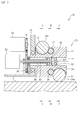
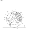
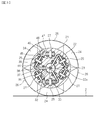
<実施例1> まず、移動搬送機構10の構成について、図1乃至図4を参照しながら説明する。図1は、移動搬送機構10の構成を示す断面図である。図2は、図1の線A-Aに沿って切断した断面図である。図3は、図1の線B-Bに沿って切断した断面図である。図4は、図1の線C-Cに沿って切断した断面図である。
図1に示すように、移動搬送機構10のケーシング12に、ホイール部材22と、第1及び第2の回転軸33,35とが回転自在に支持されている。
第1の回転軸33の一端に、ケーシング12に固定された第1のモータ52から回転が伝達される。第2の回転軸35は、第1の回転軸33の外側に、第1の回転軸33と同心に配置された中空円筒状の部材である。第2の回転軸35の一端に、ケーシング12に固定された第2のモータ54から歯車56,58を介して、回転が伝達される。
ホイール部材22の中心には貫通穴23が形成され、貫通穴23内に、ホイール部材22のホイール回転中心軸22xと同心に、第1及び第2の回転軸33,35の他端側が配置されている。第1及び第2の回転軸33,35の他端側とホイール部材22とは、軸受を介して相対回転自在に支持されている。
図1、図2及び図4に示すように、ホイール部材22は、第1及び第2の副車輪24,26を回転自在に支持している。なお、図2及び図4には、ホイール部材22に固定された軸24k,26kを中心に、第1及び第2の副車輪24,26が軸受を介して回転自在に支持される構成を示しているが、これに限るものではない。第1の副車輪24と第2の副車輪26とは、ホイール回転中心軸22x方向に離れており、第1の副車輪24と第2の副車輪26との間に差動機構30が配置されている。
図1及び図3に示すように、差動機構30は、第1及び第2の回転軸33,35の他端側に固定され互いに対向する入力かさ歯車32,34と、入力かさ歯車32,34に噛み合う3つの出力かさ歯車36とを含む。出力かさ歯車36は、出力かさ歯車軸37の一端に固定されている。出力かさ歯車軸37は、ホイール部材22に固定された軸受39によって回転自在に支持されている。出力かさ歯車軸37の他端には、かさ歯車38が固定されている。入力かさ歯車32,34は、差動機構の第1及び第2の入力部材である。出力かさ歯車36、出力かさ歯車軸37は、差動機構の出力部材である。軸受39は、回転支持部材である。
差動機構には、かさ歯車の代わりに、フェースギヤ、ハイポイドギヤなどの歯車や、円筒歯車を用いた遊星歯車装置等、歯が噛み合う構成を用いることができる。また、フリクションドライブ(摩擦伝動を利用するもの)、トラクションドライブ(トラクションオイルを利用するもの)等のように、噛み合う歯がない構成を用いてもよい。ベルトやワイヤ等を介して回転を伝達する差動機構を用いてもよい。
図2及び図4に示すように、第1及び第2の副車輪24,26は、樽状の外形を有し、第1及び第2の副車輪24,26の回転中心軸24x,26xは、ホイール回転中心軸22xを中心とする仮想円周22p,22qに沿って延在している。第1及び第2の副車輪24,26は、ホイール部材22よりも径方向外側に突出しており、ホイール部材22の回転に応じて床面2に接する。
図1に示すように、第1及び第2の副車輪24,26は、第1及び第2の副車輪24,26の外周面24a,26aに接触する第1及び第2の駆動ローラ25,27によって回転駆動される。図3に示すように、第1及び第2の駆動ローラ25,27は、それぞれ、第1及び第2の駆動ローラ軸45,47に固定され、第1及び第2の駆動ローラ軸45,47はホイール部材22に回転自在に支持されている。第1及び第2の駆動ローラ軸45,47の一端には、互いに噛み合うかさ歯車46,48が固定されている。第1の駆動ローラ軸45の他端にはかさ歯車44が固定され、このかさ歯車44は、出力かさ歯車軸37の他端に固定されたかさ歯車38と噛み合っている。これらの第1及び第2の駆動ローラ25,27と、第1及び第2の駆動ローラ軸45,47と、かさ歯車38,44,46,48は、回転伝達部材であり、出力かさ歯車軸37の回転を第1及び第2の副車輪24,26に伝達して第1及び第2の副車輪24,26を回転させる。
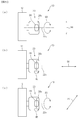
次に、移動搬送機構10の動作について、図5の模式図を参照しながら説明する。図5は、床面2から移動搬送機構10とケーシング12を見た様子を示す。図5では、ホイール部材22に第1及び第2の副車輪24,26が配置された主車輪20について、第1及び第2の副車輪24,26のうち、床面2に接する一つの副車輪28のみが図示されている。ここでは、差動機構30の一対の入力かさ歯車32,34の歯数が同じ場合をとりあげて説明する。
差動機構30の1対の入力かさ歯車32,34の両方を同じ方向に同じ角速度で回転駆動すると、出力かさ歯車36は自転することなく、ホイール回転中心軸22xのまわりを公転する。これによって、図5(a)に示すように、第1及び第2の副車輪24,26は停止した状態で、すなわち、第1及び第2の副車輪24,26が自転しない状態で、ホイール部材22が回転し、主車輪20が矢印83に示すように回転する。その結果、矢印86で示すように、ケーシング12は床面2に対して、前後方向(図5(a)において上下方向)に相対的に移動する。
差動機構30の1対の入力かさ歯車32,34を互いに逆方向に、絶対値が同じ角速度で回転駆動すると、出力かさ歯車36は公転することなく、自転する。これによって、図5(b)に示すように、ホイール部材22が停止した状態で、矢印85で示すように副車輪28が回転中心軸28xのまわりを回転(自転)する。その結果、矢印88で示すように、ケーシング12は床面2に対して、左右方向(図5(b)において左右方向)に相対的に移動する。
差動機構30の1対の入力かさ歯車32,34を互いに絶対値が異なる角速度で回転駆動すると、出力かさ歯車36は、自転し、かつ公転する。これによって、図5(c)において矢印83で示すように主車輪20が回転し、矢印85で示すように副車輪28が回転(自転)する。その結果、例えば矢印87で示すように、ケーシング12は床面2に対して図5(c)に示すように斜め方向に相対的に移動する。
移動搬送機構10は、モータ52,54の回転を制御することで、平面内の全方向の移動が可能である。
すなわち、ケーシング12を床面2に対して前後方向(図5(a)において矢印86で示す方向)に移動させたい場合には、第1及び第2の副車輪24,26が回転しない状態でホイール部材22を回転させればよいので、出力かさ歯車36が公転しかつ自転しないように、入力かさ歯車32,34の両方を同じ方向に同じ角速度(第1の角速度比)で回転駆動するように、モータ52,54の回転を制御する。
ケーシング12を床面2に対して左右方向(図5(b)において矢印88で示す方向)に移動させたい場合には、第1及び第2の副車輪24,26が自転し、ホイール部材22が回転しないようにすればよいので、出力かさ歯車36が自転しかつ公転しないように、入力かさ歯車32,34を互いに逆方向に絶対値が同じ角速度(第2の角速度比)で回転駆動するように、モータ52,54の回転を制御する。
ケーシング12を床面2に対して前後方向でも左右方向でもない斜め方向(図5(c)において、例えば矢印87で示す方向)に移動させたい場合には、第1及び第2の副車輪24,26が自転し、かつホイール部材22が回転すればよいので、出力かさ歯車36が自転しかつ公転するように、入力かさ歯車32,34を、第1の角速度の比と異なりかつ第2の角速度の比と異なる角速度比で回転駆動するように、モータ52,54の回転を制御する。
移動搬送機構10は、駆動用の全てのモータ52,54をケーシング12上に配置することができるので、使用できるモータに関する制約は少なく、幅広い種類やサイズのモータを利用することが可能である。例えば、副車輪駆動用のモータを主車輪に内蔵する場合よりも、大トルクのモータを用いることができる。したがって、副車輪のトルクを大きくすることができ、主車輪と副車輪の駆動力の差を小さくし、あるいは差を無くすことができる。また、移動搬送機構10は、モータを主車輪に内蔵しないので、モータへの電気供給等の配線が容易である。
移動搬送機構10は、図3に示すように、第1及び第2の副車輪24,26が、ホイール回転中心軸22xの方向から見ると、仮想外形円21に沿って交互に配置されている。そのため、仮想外形円21の全周に沿って副車輪24,26の間の隙間を少なくし又は無くすことができ、円周方向に隣り合う副車輪24,26間の隙間に起因する振動を、主車輪20の回転角度に制約されることなく抑制することができる。
なお、主車輪20の回転が1回転より小さい範囲に限定される場合や、主車輪20の一部の回転角度範囲での振動の抑制が必要な場合には、第1及び第2の副車輪24,26が交互に配置されない部分があっても構わない。この場合、仮想外形円21の一部分に沿って隣り合うように副車輪24,26を配置すれば、主車輪20の一部の回転角度範囲では、円周方向に隣り合う副車輪間の隙間に起因する振動を抑制することができる。
第1及び第2の副車輪24,26が樽状の形状を有していると、ホイール回転中心軸22xの方向から見たとき、第1及び第2の副車輪24,26を仮想外形円21にできるだけ近付けることができるので、主車輪20が回転(ホイール部材22が回転)したときの移動搬送機構10の振動を抑制することが容易である。
第1の副車輪24と第2の副車輪26との間に、差動機構30を配置すると、第1及び第2の副車輪24,26を回転駆動するための構成を簡素にすることができる。
第1及び第2の副車輪24,26が、第1及び第2の副車輪24,26の外周面24a,26aに接する駆動ローラ25,27によって回転駆動されるように構成すると、第1及び第2の副車輪24,26の軸方向の端部から駆動力を伝達する場合に比べるとスペースに余裕ができるため、設計が容易になる。また、第1及び第2の副車輪24,26を軸方向に長くすることができるため、第1及び第2の副車輪24,26の中に大きい軸受を配置することも可能であり、耐荷重を高めることが容易である。
<変形例1> 実施例1の変形例1について、図6を参照しながら説明する。図6は、実施例1の変形例1の移動搬送機構の要部構成図である。
図6(a)に示すように、移動搬送機構10のホイール部材22に一端側が回転自在に支持され揺動自在である支持梁50の他端側に、第1及び第2の副車輪24,26の軸24k,26kが支持されている。第1及び第2の副車輪24,26は、軸24k,26kに対して回転自在に支持されている。支持梁50は、ばね等の弾性部材62によって付勢され、鎖線で示すように、床面に接していない副車輪24s,26sが、ホイール回転中心軸から離れる方向(図では下向き)に移動し、第1及び第2の副車輪24s,26sの外周面と第1及び第2の駆動ローラ25,27との接触が解除又は低減される。実線で示すように、床面に接している副車輪24,26は、ホイール回転中心軸に近づく方向(図では上向き)に移動して、第1及び第2の駆動ローラ25,27と接触し、回転駆動される。なお、弾性部材62は無くてもよい。
図6(b)に示すように、移動搬送機構10のホイール部材22に設けられ、副車輪24,26の軸24k,26kを支持する支持箱66が、ホイール回転中心軸に近づいたり離れたりする方向(図では上下方向)に移動自在に支持されている。支持箱66は、ゴム等の弾性部材64を介して、ホイール回転中心軸から離れる方向(図では下向き)に付勢されている。第1及び第2の副車輪24,26は、軸24k,26kに対して回転自在に支持されている。鎖線で示すように、床面に接していない副車輪24t,26tは、ホイール回転中心軸から離れる方向(図では下方向)に移動し、駆動ローラ25、27との接触が解除又は低減される。実線で示すように、床面に接している副車輪24,26は、ホイール回転中心軸に近づく方向(図において上向き)に移動して、第1及び第2の駆動ローラ25,27と接触し、回転駆動される。なお、弾性部材64は無くてもよい。
このように、床面に接していない第1及び第2の副車輪24s,26s;24t,26tを、ホイール回転中心軸を中心とする径方向の外側に移動させ、床面に接していない第1及び第2の副車輪24s,26s;24t,26tと差動機構の出力部材との間の回転伝達部材による結合を解除又は低減させる駆動低減機構をさらに備えると、移動搬送機構10の移動の際に床面に接していない第1及び第2の副車輪24s,26s;24t,26tを駆動する無駄をなくして、第1及び第2の副車輪24,26を効率よく駆動することができる。
支持梁や支持箱、弾性部材の代わりに、副車輪を支持するホイール部材の一部を弾性変形しやすい構造にした駆動低減機構としてもよい。
<まとめ> 以上に説明したように、第1の副車輪24と第2の副車輪26とを、ホイール回転中心軸22xの方向に離し、かつ、ホイール回転中心軸22xの方向から見ると、仮想外形円21の内側に、仮想外形円21に接近又は接するように配置すると、円周方向に隣り合う副車輪間の隙間に起因して主車輪が回転するときに発生する振動を抑制することができる。
なお、本発明は、上記実施の形態に限定されるものではなく、種々変更を加えて実施することが可能である。
実施例1では第1の副車輪を3個、第2の副車輪を3個用いる場合をとりあげて説明したが、第1の副車輪の数や第2の副車輪の数は3以外でもよい。例えば、第1の副車輪は1個以上であればよく、第2の副車輪は1個以上であればよい。第1及び第2の副車輪は、実施例以外の方法で回転駆動しても構わない。例えば、第1及び第2の副車輪の軸端に回転伝達部材を結合して、第1及び第2の副車輪を回転させても構わない。
回転伝達部材には歯車、ベルト、歯付きベルト、チェーン、ワイヤ、回転軸、軸継手などを用いることができる。
回転伝達部材には、丸ベルトを用いてもよい。丸ベルトの循環経路を折り曲げることにより、差動機構と副車輪との間の伝達経路が簡単になる。丸ベルトは、通常は、断面が円形の無端ベルト部材であるが、断面が一定の大きさでなくてもよく、例えば、中心軸方向に断面の大きさが周期的に変化して表面に歯のような凹凸形状が形成されるものであってもよい。
回転伝達部材には、副車輪に係合し、副車輪の外周面のうち接地面に沿って延在する表面を有する無端循環部材を用いてもよい。
副車輪と駆動ローラとが接触する面に、凸部及び凹部を形成して噛み合わせるようにすれば、駆動ローラと副車輪との間ですべりが生じるのを防ぎ、副車輪が確実に回転駆動されるようにすることができる。
副車輪の形状は樽状の形状以外でもよい。
副車輪は、その回転中心軸の少なくとも一部を円弧状に保ったままその回転中心軸のまわりを変形しながら回転するものでもよい。例えば、弾性部材を用いたり、円筒形状の部品を蛇腹状に重ね合わせたりすることによって、その回転中心軸を円弧状に保ったままその回転中心軸のまわりを変形しながら回転するように構成してもよい。
複数個の副車輪を用いる場合は、回転伝達部材を介して全ての副車輪が直接回転されるようにしてもよい。あるいは、回転伝達部材を介して直接は回転されない副車輪が、回転伝達部材を介して直接回転される副車輪と回転が伝わるように連結され、両方の副車輪が同時に回転されるようにしてもよい。
第1の副車輪と第2の副車輪に加えて、他の副車輪を用いてもよい。例えば、ホイール回転中心軸方向に第1の副車輪と第2の副車輪から離れた(第1の仮想円周と第2の仮想円周から離れた)位置において、ホイール回転中心軸を中心とする第3の仮想円周に沿って延在する回転中心軸を中心に回転自在に、ホイール部材に支持された第3の副車輪を用いてもよい。この場合、第1乃至第3の副車輪は、ホイール回転中心軸の方向から見ると、ホイール回転中心軸を中心とする仮想外形円の内側に、仮想外形円に接近又は接するように配置され、かつ、仮想外形円に沿って第1の副車輪の隣に第2の副車輪が配置され、第2の副車輪の隣に第3の副車輪が配置されてもよい。さらに、仮想外形円に沿って第3の副車輪の隣に第1の副車輪が配置されて、仮想外形円に沿って第1の副車輪、第2の副車輪、第3の副車輪、第1の副車輪、第2の副車輪、・・・の順に配置されてもよい。同様に、第1乃至第3の副車輪に加えて、さらに他の副車輪を用いてもよい。第1及び第2の副車輪以外の他の副車輪は、回転駆動されるものでも、回転自在なもの(回転駆動されないもの)でもよい。他の副車輪が回転駆動される場合、第1及び第2の副車輪に回転を伝達する差動機構から他の副車輪に回転が伝達されても、第1及び第2の副車輪に回転を伝達する差動機構とは別系統から他の副車輪に回転が伝達されてもよい。
出力かさ歯車の数は3以外でもよい。1つの出力かさ歯車が第1及び第2の副車輪の両方を駆動してもよいし、第1及び第2の副車輪を駆動する出力かさ歯車を別々にしてもよい。1つの出力かさ歯車が1つの副車輪を駆動してもよい。
差動機構は第1の副車輪と第2の副車輪の間以外に配置してもよい。
樽状の形状の副車輪は外周面の場所によって副車輪の回転中心軸からの半径が異なるため、副車輪の角速度が一定でも場所によって外周面上の速度が異なる。副車輪の回転による床面上の移動速度を、狙った速度にするためには、副車輪の外周面の床面に接している場所に応じて、差動機構の入力部材の角速度を調整すればよい。
本発明の移動搬送機構は、副車輪が下方に突出して床面等に接する移動搬送装置に限らず、上下を反転した構成で用いることもできる。例えば、上方に突出した副車輪で被搬送物を下から支え、主車輪及び副車輪の回転の組み合わせによって、被搬送物を所望の方向に移動させたり旋回させたりする移動搬送装置にも用いることができる。
本発明は、前進・後進のみならず、横方向、斜め方向の移動が求められる機器、例えば、車椅子、高齢者用移動装置などの福祉機器や、工場や倉庫で使用される搬送台車、搬送車、フォークリフト、移動車両などの移動搬送機器などの用途に適用できる。
2 床面(接触面)
10 移動搬送機構
12 ケーシング
20 主車輪
21 仮想外形円
22 ホイール部材
22p 仮想円周(第1の仮想円周)
22q 仮想円周(第2の仮想円周)
22x ホイール回転中心軸
24 第1の副車輪
24x 回転中心軸
25 第1の駆動ローラ(回転伝達部材)
26 第2の副車輪
26x 回転中心軸
27 第2の駆動ローラ(回転伝達部材)
28 副車輪
28x 回転中心軸
30 差動機構
32 入力かさ歯車(差動機構の第1の入力部材)
33 第1の回転軸
34 入力かさ歯車(差動機構の第2の入力部材)
35 第2の回転軸
36 出力かさ歯車(差動機構の出力部材)
37 出力かさ歯車軸(差動機構の出力部材)
38 かさ歯車(回転伝達部材)
39 軸受(回転支持部材)
44 かさ歯車(回転伝達部材)
45 第1の駆動ローラ軸(回転伝達部材)
46 かさ歯車(回転伝達部材)
47 第2の駆動ローラ軸(回転伝達部材)
48 かさ歯車(回転伝達部材)
50 支持梁(駆動低減機構)
52 第1のモータ
54 第2のモータ
62,64 弾性部材(駆動低減機構)
66 支持箱(駆動低減機構)
10 移動搬送機構
12 ケーシング
20 主車輪
21 仮想外形円
22 ホイール部材
22p 仮想円周(第1の仮想円周)
22q 仮想円周(第2の仮想円周)
22x ホイール回転中心軸
24 第1の副車輪
24x 回転中心軸
25 第1の駆動ローラ(回転伝達部材)
26 第2の副車輪
26x 回転中心軸
27 第2の駆動ローラ(回転伝達部材)
28 副車輪
28x 回転中心軸
30 差動機構
32 入力かさ歯車(差動機構の第1の入力部材)
33 第1の回転軸
34 入力かさ歯車(差動機構の第2の入力部材)
35 第2の回転軸
36 出力かさ歯車(差動機構の出力部材)
37 出力かさ歯車軸(差動機構の出力部材)
38 かさ歯車(回転伝達部材)
39 軸受(回転支持部材)
44 かさ歯車(回転伝達部材)
45 第1の駆動ローラ軸(回転伝達部材)
46 かさ歯車(回転伝達部材)
47 第2の駆動ローラ軸(回転伝達部材)
48 かさ歯車(回転伝達部材)
50 支持梁(駆動低減機構)
52 第1のモータ
54 第2のモータ
62,64 弾性部材(駆動低減機構)
66 支持箱(駆動低減機構)
Claims (4)
- ホイール回転中心軸を中心に回転自在に支持されるホイール部材と、
前記ホイール回転中心軸を中心とする第1の仮想円周に沿って延在する回転中心軸を中心に回転自在に、前記ホイール部材に支持された第1の副車輪と、
前記ホイール回転中心軸方向に前記第1の仮想円周から離れた位置において、前記ホイール回転中心軸を中心とする第2の仮想円周に沿って延在する回転中心軸を中心に回転自在に、前記ホイール部材に支持された第2の副車輪と、
前記ホイール回転中心軸と同軸に回転自在に配置された第1及び第2の入力部材と、前記第1及び第2の入力部材の両方に接触し、自転中心軸を中心に自転可能、かつ、前記ホイール回転中心軸のまわりを公転可能である出力部材とを含む差動機構と、
前記ホイール部材に固定され、前記差動機構の前記出力部材を、前記自転中心軸を中心に回転自在に支持する回転支持部材と、
前記第1及び第2の副車輪のうち少なくとも一つの副車輪と前記差動機構の前記出力部材との間を結合し、前記出力部材の前記自転中心軸を中心とする自転による回転を当該副車輪に伝達して当該副車輪を回転させる回転伝達部材と、
を備え、
前記第1及び第2の副車輪は、前記ホイール回転中心軸の方向から見ると、前記ホイール回転中心軸を中心とする仮想外形円の内側に、前記仮想外形円に接近又は接するように配置され、かつ、
前記仮想外形円に沿って前記第1の副車輪の隣に前記第2の副車輪が配置され、
前記ホイール部材は、前記差動機構の前記出力部材の前記ホイール回転中心軸のまわりの公転に伴って、前記ホイール回転中心軸を中心に回転することを特徴とする移動搬送機構。 - 前記第1及び第2の副車輪は、前記ホイール回転中心軸の方向から見ると、前記仮想外形円に沿って交互に配置されていることを特徴とする、請求項1に記載の移動搬送機構。
- 前記ホイール回転中心軸方向に垂直な方向から見ると、前記第1の副車輪と前記第2の副車輪は前記ホイール回転中心軸方向に離れて配置され、前記第1の副車輪と前記第2の副車輪の間に前記差動機構が配置されていることを特徴とする、請求項1又は2に記載の移動搬送機構。
- 接触面に接していない前記第1及び第2の副車輪を、前記ホイール回転中心軸を中心とする径方向の外側に移動させ、当該第1及び第2の副車輪と前記差動機構の前記出力部材との間の前記回転伝達部材による結合を解除又は低減させる駆動低減機構をさらに備えたことを特徴とする、請求項1乃至3のいずれか一つに記載の移動搬送機構。
Priority Applications (1)
| Application Number | Priority Date | Filing Date | Title |
|---|---|---|---|
| JP2016512731A JP6422482B2 (ja) | 2014-04-10 | 2015-04-06 | 移動搬送機構 |
Applications Claiming Priority (2)
| Application Number | Priority Date | Filing Date | Title |
|---|---|---|---|
| JP2014-081457 | 2014-04-10 | ||
| JP2014081457 | 2014-04-10 |
Publications (1)
| Publication Number | Publication Date |
|---|---|
| WO2015156263A1 true WO2015156263A1 (ja) | 2015-10-15 |
Family
ID=54287839
Family Applications (1)
| Application Number | Title | Priority Date | Filing Date |
|---|---|---|---|
| PCT/JP2015/060779 Ceased WO2015156263A1 (ja) | 2014-04-10 | 2015-04-06 | 移動搬送機構 |
Country Status (2)
| Country | Link |
|---|---|
| JP (1) | JP6422482B2 (ja) |
| WO (1) | WO2015156263A1 (ja) |
Cited By (5)
| Publication number | Priority date | Publication date | Assignee | Title |
|---|---|---|---|---|
| WO2017212754A1 (ja) * | 2016-06-07 | 2017-12-14 | 国立大学法人東北大学 | 全方向回転駆動機構および移動体 |
| WO2018056416A1 (ja) * | 2016-09-23 | 2018-03-29 | 一志株式会社 | 移動輸送機構 |
| JP2019093817A (ja) * | 2017-11-21 | 2019-06-20 | 国立大学法人京都大学 | 移動装置 |
| WO2024135304A1 (ja) * | 2022-12-21 | 2024-06-27 | ソニーグループ株式会社 | 移動体及び移動方法 |
| US20250074109A1 (en) * | 2023-09-04 | 2025-03-06 | Hyundai Motor Company | Omnidirectional rotation drive device |
Citations (3)
| Publication number | Priority date | Publication date | Assignee | Title |
|---|---|---|---|---|
| JP2009179110A (ja) * | 2008-01-29 | 2009-08-13 | Kyoto Univ | 移動搬送機構 |
| JP2013532600A (ja) * | 2010-07-23 | 2013-08-19 | トヨタ モーター エンジニアリング アンド マニュファクチャリング ノース アメリカ,インコーポレイティド | 全方位駆動車輪システム及びその操作方法 |
| JP2013256212A (ja) * | 2012-06-13 | 2013-12-26 | Kyomachi Sangyo Sharyo Kk | 車輪 |
-
2015
- 2015-04-06 JP JP2016512731A patent/JP6422482B2/ja active Active
- 2015-04-06 WO PCT/JP2015/060779 patent/WO2015156263A1/ja not_active Ceased
Patent Citations (3)
| Publication number | Priority date | Publication date | Assignee | Title |
|---|---|---|---|---|
| JP2009179110A (ja) * | 2008-01-29 | 2009-08-13 | Kyoto Univ | 移動搬送機構 |
| JP2013532600A (ja) * | 2010-07-23 | 2013-08-19 | トヨタ モーター エンジニアリング アンド マニュファクチャリング ノース アメリカ,インコーポレイティド | 全方位駆動車輪システム及びその操作方法 |
| JP2013256212A (ja) * | 2012-06-13 | 2013-12-26 | Kyomachi Sangyo Sharyo Kk | 車輪 |
Cited By (10)
| Publication number | Priority date | Publication date | Assignee | Title |
|---|---|---|---|---|
| WO2017212754A1 (ja) * | 2016-06-07 | 2017-12-14 | 国立大学法人東北大学 | 全方向回転駆動機構および移動体 |
| JPWO2017212754A1 (ja) * | 2016-06-07 | 2019-04-25 | 国立大学法人東北大学 | 全方向回転駆動機構および移動体 |
| US10843506B2 (en) | 2016-06-07 | 2020-11-24 | Tohoku University | Omni-directional rotational drive mechanism and moving body |
| WO2018056416A1 (ja) * | 2016-09-23 | 2018-03-29 | 一志株式会社 | 移動輸送機構 |
| CN109863040A (zh) * | 2016-09-23 | 2019-06-07 | 一志株式会社 | 移动运输机构 |
| JPWO2018056416A1 (ja) * | 2016-09-23 | 2019-07-04 | 一志株式会社 | 移動輸送機構 |
| CN109863040B (zh) * | 2016-09-23 | 2022-06-03 | 一志株式会社 | 移动运输机构 |
| JP2019093817A (ja) * | 2017-11-21 | 2019-06-20 | 国立大学法人京都大学 | 移動装置 |
| WO2024135304A1 (ja) * | 2022-12-21 | 2024-06-27 | ソニーグループ株式会社 | 移動体及び移動方法 |
| US20250074109A1 (en) * | 2023-09-04 | 2025-03-06 | Hyundai Motor Company | Omnidirectional rotation drive device |
Also Published As
| Publication number | Publication date |
|---|---|
| JPWO2015156263A1 (ja) | 2017-04-13 |
| JP6422482B2 (ja) | 2018-11-14 |
Similar Documents
| Publication | Publication Date | Title |
|---|---|---|
| JP6422482B2 (ja) | 移動搬送機構 | |
| JP5158698B2 (ja) | 移動搬送機構 | |
| CN105882784B (zh) | 全向移动平台及其动力万向轮 | |
| JP6950646B2 (ja) | 全方向移動型車輪 | |
| CN105946451B (zh) | 全向移动平台及其舵轮和驱动轮 | |
| JP6821201B2 (ja) | 全方向回転駆動機構および移動体 | |
| CN106364259B (zh) | 减速驱动轮及应用该减速驱动轮的机器人 | |
| CN110733335B (zh) | 传动机构、行走系统及探月机器人 | |
| CN103465779A (zh) | 双引擎全向四驱行进机构 | |
| CN108422803A (zh) | 搬运台车用的驱动装置 | |
| CN205891045U (zh) | 全向移动平台及其动力万向轮 | |
| US20150362045A1 (en) | Transmission device | |
| JP2009083660A (ja) | 走行台車 | |
| JP2016203683A (ja) | 摩擦式走行装置および全方向移動装置 | |
| CN109863040B (zh) | 移动运输机构 | |
| WO2013022017A1 (ja) | 多方向移動体モジュール | |
| KR20160141556A (ko) | 다기능 이동이 가능한 로봇 바퀴장치 | |
| KR102383027B1 (ko) | 전방향 구동 장치 및 전방향 구동 차량 | |
| JP6931848B2 (ja) | 移動装置 | |
| CN110906106A (zh) | 爬行机器人行走机构及爬行机器人 | |
| KR101680318B1 (ko) | 전방향 휠 구조체 | |
| CN110834494B (zh) | 一种万向轮及具有该万向轮的载体 | |
| JP5818241B2 (ja) | 球体駆動モジュール及びそれを用いた搬送装置 | |
| JP2017128187A (ja) | 移動体 | |
| CN115535065A (zh) | 移动底盘及移动机器人 |
Legal Events
| Date | Code | Title | Description |
|---|---|---|---|
| 121 | Ep: the epo has been informed by wipo that ep was designated in this application |
Ref document number: 15776483 Country of ref document: EP Kind code of ref document: A1 |
|
| ENP | Entry into the national phase |
Ref document number: 2016512731 Country of ref document: JP Kind code of ref document: A |
|
| NENP | Non-entry into the national phase |
Ref country code: DE |
|
| 122 | Ep: pct application non-entry in european phase |
Ref document number: 15776483 Country of ref document: EP Kind code of ref document: A1 |