WO2015156153A1 - 蛍光観察内視鏡システム - Google Patents
蛍光観察内視鏡システム Download PDFInfo
- Publication number
- WO2015156153A1 WO2015156153A1 PCT/JP2015/059654 JP2015059654W WO2015156153A1 WO 2015156153 A1 WO2015156153 A1 WO 2015156153A1 JP 2015059654 W JP2015059654 W JP 2015059654W WO 2015156153 A1 WO2015156153 A1 WO 2015156153A1
- Authority
- WO
- WIPO (PCT)
- Prior art keywords
- light
- fluorescence
- wavelength band
- imaging
- wavelength
- Prior art date
Links
Images


Classifications
-
- A—HUMAN NECESSITIES
- A61—MEDICAL OR VETERINARY SCIENCE; HYGIENE
- A61B—DIAGNOSIS; SURGERY; IDENTIFICATION
- A61B1/00—Instruments for performing medical examinations of the interior of cavities or tubes of the body by visual or photographical inspection, e.g. endoscopes; Illuminating arrangements therefor
- A61B1/06—Instruments for performing medical examinations of the interior of cavities or tubes of the body by visual or photographical inspection, e.g. endoscopes; Illuminating arrangements therefor with illuminating arrangements
- A61B1/0638—Instruments for performing medical examinations of the interior of cavities or tubes of the body by visual or photographical inspection, e.g. endoscopes; Illuminating arrangements therefor with illuminating arrangements providing two or more wavelengths
-
- A—HUMAN NECESSITIES
- A61—MEDICAL OR VETERINARY SCIENCE; HYGIENE
- A61B—DIAGNOSIS; SURGERY; IDENTIFICATION
- A61B1/00—Instruments for performing medical examinations of the interior of cavities or tubes of the body by visual or photographical inspection, e.g. endoscopes; Illuminating arrangements therefor
- A61B1/00002—Operational features of endoscopes
- A61B1/00004—Operational features of endoscopes characterised by electronic signal processing
- A61B1/00006—Operational features of endoscopes characterised by electronic signal processing of control signals
-
- A—HUMAN NECESSITIES
- A61—MEDICAL OR VETERINARY SCIENCE; HYGIENE
- A61B—DIAGNOSIS; SURGERY; IDENTIFICATION
- A61B1/00—Instruments for performing medical examinations of the interior of cavities or tubes of the body by visual or photographical inspection, e.g. endoscopes; Illuminating arrangements therefor
- A61B1/00002—Operational features of endoscopes
- A61B1/00004—Operational features of endoscopes characterised by electronic signal processing
- A61B1/00009—Operational features of endoscopes characterised by electronic signal processing of image signals during a use of endoscope
-
- A—HUMAN NECESSITIES
- A61—MEDICAL OR VETERINARY SCIENCE; HYGIENE
- A61B—DIAGNOSIS; SURGERY; IDENTIFICATION
- A61B1/00—Instruments for performing medical examinations of the interior of cavities or tubes of the body by visual or photographical inspection, e.g. endoscopes; Illuminating arrangements therefor
- A61B1/00002—Operational features of endoscopes
- A61B1/00043—Operational features of endoscopes provided with output arrangements
- A61B1/00045—Display arrangement
- A61B1/0005—Display arrangement combining images e.g. side-by-side, superimposed or tiled
-
- A—HUMAN NECESSITIES
- A61—MEDICAL OR VETERINARY SCIENCE; HYGIENE
- A61B—DIAGNOSIS; SURGERY; IDENTIFICATION
- A61B1/00—Instruments for performing medical examinations of the interior of cavities or tubes of the body by visual or photographical inspection, e.g. endoscopes; Illuminating arrangements therefor
- A61B1/04—Instruments for performing medical examinations of the interior of cavities or tubes of the body by visual or photographical inspection, e.g. endoscopes; Illuminating arrangements therefor combined with photographic or television appliances
- A61B1/043—Instruments for performing medical examinations of the interior of cavities or tubes of the body by visual or photographical inspection, e.g. endoscopes; Illuminating arrangements therefor combined with photographic or television appliances for fluorescence imaging
-
- A—HUMAN NECESSITIES
- A61—MEDICAL OR VETERINARY SCIENCE; HYGIENE
- A61B—DIAGNOSIS; SURGERY; IDENTIFICATION
- A61B1/00—Instruments for performing medical examinations of the interior of cavities or tubes of the body by visual or photographical inspection, e.g. endoscopes; Illuminating arrangements therefor
- A61B1/06—Instruments for performing medical examinations of the interior of cavities or tubes of the body by visual or photographical inspection, e.g. endoscopes; Illuminating arrangements therefor with illuminating arrangements
- A61B1/07—Instruments for performing medical examinations of the interior of cavities or tubes of the body by visual or photographical inspection, e.g. endoscopes; Illuminating arrangements therefor with illuminating arrangements using light-conductive means, e.g. optical fibres
Definitions
- the present invention relates to a fluorescence observation endoscope system that performs fluorescence observation.
- the contents of displaying a normal light image (normal image) and one ICG fluorescent image, a normal light image, and two different fluorescent images are displayed.
- the content of displaying a composite image obtained by image synthesis with an image of difference calculation is disclosed.
- the above-described conventional example does not disclose details of color display in a display image when displaying a composite image obtained by calculating a difference between a normal light image and a fluorescence image.
- a fluorescent image it is difficult to understand the outline and color tone of an organ or biological tissue only with the fluorescent image, so when performing treatment using a treatment tool, the difference between the contour and color tone of the organ or biological tissue is reflected. It is desirable to be able to display them. For example, since it becomes difficult to distinguish a fat-rich tissue having a different color tone from a membranous tissue only by the outline, it is desirable to display the color tone in a reflected manner.
- the present invention has been made in view of the above-described points, and an object thereof is to provide a fluorescence observation endoscope system capable of generating a fluorescence image and an image reflecting a difference in contour and color tone of a living tissue. .
- the fluorescence observation endoscope system includes light in a first wavelength band that emits fluorescence by irradiating a medicine administered to a living body, and light in the first wavelength band that is visible light.
- a light source capable of simultaneously emitting light in a second wavelength band in a different wavelength band and light in a third wavelength band that is visible light and is different from the light in the first and second wavelength bands
- An imaging device configured to have an imaging device that simultaneously receives the device, the fluorescence, and the reflected light of the light in the second and third wavelength bands, and the fluorescence imaging signal acquired by the imaging unit;
- a signal processing device that performs image processing to generate color display images to be displayed in different colors from the second and third imaging signals acquired from the reflected light of the light in the second and third wavelength bands, Is provided.
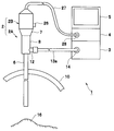
- FIG. 1 is a diagram showing an overall configuration of a fluorescence observation endoscope system according to a first embodiment of the present invention.
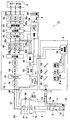
- FIG. 2 is a diagram showing the fluorescence observation endoscope system in a state where the internal configuration of the endoscope, the video processor, and the like in FIG. 1 is shown.
- FIG. 3A is a diagram showing a wavelength band of illumination light emitted when the light source device is in a fluorescence observation mode.
- FIG. 3B is a diagram illustrating a wavelength band of illumination light emitted when the light source device is in a normal light observation mode.
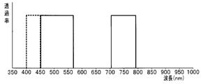
- FIG. 4 is a diagram illustrating a transmission characteristic of a light receiving filter provided in an imaging unit and a range of a wavelength band shielded by an excitation light cut filter.
- FIG. 1 is a diagram showing an overall configuration of a fluorescence observation endoscope system according to a first embodiment of the present invention.
- FIG. 2 is a diagram showing the fluorescence observation endoscope system in
- FIG. 5 is a flowchart showing typical operation contents of the first embodiment of the present invention.
- FIG. 6 is a diagram illustrating an overall configuration of a fluorescence observation endoscope system according to a first modification of the first embodiment.
- FIG. 7 is a diagram showing a wavelength band of illumination light emitted when the light source device is in a fluorescence observation mode or the like in the first modification.
- FIG. 8 is a diagram illustrating a transmission characteristic of a light receiving filter provided in an imaging unit and a range of a wavelength band shielded by an excitation light cut filter in the first modification.
- FIG. 9 is a diagram illustrating an overall configuration of a fluorescence observation endoscope system according to a second modification of the first embodiment.
- FIG. 10 is a diagram showing a wavelength band of illumination light emitted from the light source device in the second modification example in the fluorescence observation mode or the like.
- FIG. 11 is a diagram illustrating the transmission characteristics of the light receiving filter of the imaging unit in the second modification.
- FIG. 12A is a diagram showing an overall configuration of a fluorescence observation endoscope system of a third modification of the first embodiment.
- FIG. 12B is a diagram showing a light source device in a fourth modification of the first embodiment.
- FIG. 13 is a diagram showing an overall configuration of a fluorescence observation endoscope system according to a second embodiment of the present invention.
- FIG. 14 is a diagram illustrating transmission characteristics of a dichroic prism provided in the imaging unit.
- FIG. 15 is a diagram showing an overall configuration of a fluorescence observation endoscope system according to a first modification of the second embodiment of the present invention.
- FIG. 16A is a diagram illustrating a wavelength band range that the excitation light cut filter shields, together with transmission characteristics of a dichroic prism provided in the imaging unit according to the first modification.
- FIG. 16B is a diagram showing the transmission characteristics of the excitation filter provided in the light source device in the first modification.
- FIG. 17 is a diagram showing the relationship between a plurality of types of autofluorescent substances and the corresponding excitation wavelengths and fluorescence wavelengths in a tabular form.
- FIG. 18 is a diagram showing an overall configuration of a fluorescence observation endoscope system according to a second modification of the second embodiment of the present invention.
- FIG. 19A is a diagram illustrating transmission characteristics of a dichroic prism provided in an imaging unit and a range of a wavelength band that is blocked by an excitation light cut filter.
- FIG. 19B is a diagram illustrating a wavelength band of illumination light emitted from the light source device through the excitation filter in the fluorescence observation mode.
- the fluorescence observation endoscope system 1 As shown in FIG. 1, the fluorescence observation endoscope system 1 according to the first embodiment of the present invention is inserted into a subject such as an abdomen 10 and picks up an image of a subject such as a living tissue in the subject.
- An endoscope 2 that outputs signals, a light source device 3 that emits illumination light for illuminating the subject to the endoscope 2, and an imaging unit (or an imaging device) built in the endoscope 2
- the video processor 4 as a signal processing device that drives and performs signal processing on the imaging signal output from the endoscope 2 and outputs the signal as an image signal (video signal), and the image signal output from the video processor 4
- a color monitor 5 as a color display device for displaying an image of the subject image.
- An endoscope 2 shown in FIG. 1 includes an optical endoscope 2A having an elongated insertion portion 6, and a television camera 2B mounted on an eyepiece portion 7 of the optical endoscope 2A and incorporating an image pickup device. Is done.
- the present invention is not limited to the endoscope 2 in which the television camera 2B is mounted on the optical endoscope 2A shown in FIG.
- the endoscope 2 is provided, for example, at an elongated insertion portion 6 inserted into the abdomen 10 of a patient, a gripping portion 8 provided at the rear end (base end) of the insertion portion 6, and a rear end of the gripping portion 8. And an eyepiece 7 formed.
- a light guide 11 is inserted into the insertion portion 6 as an illumination light transmission member for transmitting illumination light emitted from the light source device 3, and its rear end is near the grip portion 8. It reaches the light guide base 12.
- One end of a cable 13 a through which the light guide 13 is inserted is connected to the light guide base 12, and the light guide connector 14 at the other end is detachably connected to the light source device 3.
- the light source device 3 emits (generates) illumination light for fluorescence observation and illumination light for normal light observation as described later according to the observation mode.
- the illumination light of the light source device 3 passes through the light guide 13 and the light guide 11, further passes through the illumination lens 15 from the tip of the light guide 11, and the living body (tissue) side to be observed such as the affected part 16 (see FIG. 1) in the body cavity. Is emitted.
- the illumination lens 15 is provided in an illumination window provided on the distal end surface of the insertion portion 6.
- An observation window is provided adjacent to the illumination window, and an objective lens 17 is arranged in the observation window, and the objective lens 17 forms an optical image by light from the subject side on the illuminated affected part 16 side.
- the optical image by the objective lens 17 is transmitted to the rear side by a relay lens system 18 as an optical image transmission member disposed from the insertion portion 6 to the vicinity of the eyepiece portion 7.
- an optical image transmission member may be formed using an image guide formed by a fiber bundle.
- An eyepiece lens 19 is disposed in the eyepiece unit 7, and in the case of an optical image in the visible wavelength region, a user such as an operator can observe with the naked eye via the eyepiece lens 19.
- an imaging lens 21 and, for example, a charge coupled device (abbreviated as CCD) as an imaging device constituting an imaging unit in which an imaging surface is disposed at the imaging position. ) 22 is provided in the television camera 2B attached to the eyepiece 7, an imaging lens 21 and, for example, a charge coupled device (abbreviated as CCD) as an imaging device constituting an imaging unit in which an imaging surface is disposed at the imaging position. ) 22 is provided.
- CCD charge coupled device
- an R filter 24a, a G filter 24b, and a B filter 24c color filters that transmit light in each wavelength band of red (R), green (G), and blue (B), respectively. 4 is provided for each pixel forming the imaging surface of the CCD 22.
- the imaging unit may be defined as having an imaging element, and in addition to the imaging element, an optical element such as an imaging lens 21 that forms an optical image on the imaging surface of the imaging element. It may be defined by including the system.
- FIG. 4 shows an example of transmission characteristics of the R filter 24a, the G filter 24b, and the B filter 24c constituting the mosaic filter 24.
- the transmission characteristic of FIG. 4 is the light which each permeate
- the vertical axis is expressed as transmittance (sensitivity).
- the reflected light is reflected on the subject side when the illumination light (excitation light) is irradiated on the incident light side from the imaging surface of the CCD 22 so that the fluorescence observation can be performed as described above.
- An excitation light cut filter 25 is disposed as a cut filter that cuts off the incident reflected light on a pixel that receives fluorescence (in the present embodiment, a pixel that receives light transmitted through the R filter 24a). In FIG. 2, for example, the excitation light cut filter 25 is disposed in front of the imaging lens 21, but is not limited to this position.
- ICG indocyanine green
- a fluorescent agent also referred to simply as a drug
- the excitation light cut filter 25 in this embodiment is set to a characteristic that cuts the range of the wavelength band of the excitation light that excites the ICG and transmits the wavelength band of fluorescence that peaks at the wavelength ⁇ fm. Yes.
- the light shielding range (wavelength band to be shielded) by the excitation light cut filter 25 is indicated by a dotted line with transmittance. Specifically, light in the wavelength band of 710 nm to 790 nm is sufficiently cut (for example, light is shielded with a transmittance close to 0%). In other wavelength bands, the excitation light cut filter 25 transmits with a large transmittance.
- the fluorescence in the near-infrared wavelength band of 790 nm to 900 or 790 nm to 850 in the wavelength range longer than the end value 790 nm in the wavelength band cut by the excitation light cut filter 25 is R.
- Light is received using the transmission characteristics of the filter 24a on the infrared wavelength band side.
- the R filter 24a has a characteristic of transmitting on a longer wavelength side than 900 nm, but ICG has a sufficiently small intensity of generating fluorescence in the vicinity of 850 nm or 900 nm. For this reason, the light having a wavelength longer than 850 or 900 nm may be cut and received.
- the television camera 2B is provided with an observation mode switching switch (also simply referred to as a switching switch) 26 as observation mode switching means for switching the observation mode.
- observation mode switching switch also simply referred to as a switching switch
- a signal connector 28 provided at an end of the signal cable 27 extending from the TV camera 2B is detachably connected to the video processor 4.
- the light source device 3 when the mode is switched to the fluorescence observation mode by the changeover switch 26, the light source device 3 emits excitation light (light of the first wavelength band for generating fluorescence as shown in FIG. 3A).
- excitation light light of the first wavelength band for generating fluorescence as shown in FIG. 3A.
- light of 710 nm to 790 nm is different from the first wavelength band, and lights of the second and third wavelength bands that are included in the visible wavelength band and are different from each other are simultaneously emitted as illumination light.
- the light in the second and third wavelength bands corresponds to light in the G and B wavelength bands as shown in FIG. 3A, and is also referred to as G light and B light, respectively.
- the CCD 22 as the imaging unit receives pixels that have passed through the R filter 24a (in other words, a pixel including the R filter 24a, and further simplified, abbreviated as a pixel of the R filter 24a).
- the pixel that captures the fluorescence and receives the light transmitted through the G filter 24b and the pixel that receives the light transmitted through the B filter 24c (abbreviated as a pixel of the G filter 24b and a pixel of the B filter 24c)
- the reflected light of the B light is imaged to generate a reference light image (reflected light image) (for complementing the fluorescence image).
- the video processor 4 also detects the fluorescence image signal and the reflected light image (or reference) from the fluorescence imaging signal acquired by the CCD 22 as a single imaging device forming the imaging unit and the reflected light of the reference light.
- Two image signals (light image) are generated, and a display image for displaying the fluorescent image and the reflected light image in different colors on the color monitor 5 is generated.
- the reflected light images of two different wavelength bands are displayed in different colors together with the fluorescent image, and together with the fluorescent image by fluorescence and the outline or structure of biological tissue that cannot be understood from the fluorescent image.
- the reflected light image (reference light image) by the reflected light reflecting the color tone corresponding to different living tissues can be displayed.
- the light source device 3 When the changeover switch 26 is used to switch to the normal light observation mode, the light source device 3 does not emit the excitation light in the fluorescence observation mode, and the light in the second wavelength band and the light in the third wavelength band. Together with (G light and B light), light in the R wavelength band, that is, R light is emitted.
- the light source device 3 includes white light emitting diodes (abbreviated as white LEDs) 31 a and 31 b that generate white light, excitation light 31 c that generates (at least) excitation light (light including the wavelength band), and optical Dichroic mirrors 32a, 32b, and 32c as elements, a condenser lens 33, and a light emission control unit (or light emission control circuit) 34 are provided.
- white LEDs white light emitting diodes
- excitation light 31 c that generates (at least) excitation light (light including the wavelength band)
- optical Dichroic mirrors 32a, 32b, and 32c as elements
- condenser lens 33 condenser lens
- a light emission control unit or light emission control circuit
- the white LED 31a and the dichroic mirror 32a simultaneously generate light in the second and third wavelength bands.
- the white LED 31a generates white light covering a visible wavelength band, and this white light is G corresponding to light in the second and third wavelength bands by a dichroic mirror 32a disposed on an optical path facing the white LED 31a. Only the light and the B light are selectively reflected, and enter the end surface of the light guide 13 (the G light and the B light) through the condenser lens 33 arranged on the reflection light path.
- the dichroic mirror 32a selectively reflects only G light and B light as light in the second and third wavelength bands, and selects light in a wavelength band longer than the G light and B light.
- the white light of the white LED 31a is band-limited by the dichroic mirror 32a, and the light within the wavelength band of 400 nm to 570 nm in FIG. 3A (almost G light and B light) is emitted to the light guide 13 side. The light is irradiated to the subject side through the light guide 11.
- the white LED 31b and the dichroic mirror 32b are light other than light in the second and third wavelength bands in the visible wavelength band, specifically, light in the wavelength band of 570 nm to 700 nm. (Approximately R light) is generated.
- the white light from the white LED 31b is selectively reflected by the dichroic mirror 32b disposed on the optical path facing the white LED 31b, and is transmitted through the dichroic mirror 32a disposed on the reflected light path, thereby collecting the condensing lens. Then, the light is incident on the end face of the light guide 13.
- the white LEDs 31 a and 31 b emit light, and white light in a visible wavelength region is incident on the end face of the light guide 13.
- the excitation LED 31c generates excitation light in the vicinity of the cut wavelength band that is cut by the excitation light cut filter, and this excitation light is light within the cut wavelength band by the dichroic mirror 32c disposed on the optical path facing the excitation LED 31c. Only the light is selectively reflected, passes through the dichroic mirrors 32 b and 32 a arranged on the reflected light path, and further enters the end face of the light guide 13 through the condenser lens 33.
- the dichroic mirror 32c has a characteristic of selectively reflecting only light within the cut wavelength band as described above. Accordingly, the excitation light of the excitation LED 31c is band-limited by the dichroic mirror 32c, and light within a wavelength band of, for example, 710 nm to 790 nm in FIG. 3A passes through the dichroic mirrors 32b and 32a as excitation light, and the light guide 13 The light is emitted to the object side, and further irradiated to the subject side through the light guide 11.
- the excitation light is not limited to the band limitation of the excitation light by the dichroic mirror 32c, and the excitation LED 31c may generate the excitation light within the cut wavelength band.
- the light emission control unit 34 causes the white LED 31a and the excitation LED 31c to emit light simultaneously, and emits illumination light in the wavelength band illustrated in FIG. 3A.
- the light emission control unit 34 causes the white LED 31a and the white LED 31b to emit light at the same time, and emits illumination light in the visible wavelength band shown in FIG. 3B.
- an excitation filter 81 or a band limiting filter that cuts light with a short wavelength of, for example, 450 nm or less including an excitation wavelength that generates autofluorescence is disposed on the illumination optical path. The autofluorescence may be reduced from being mixed into the fluorescence of the fluorescent agent to be observed.
- the R filter 24a, G filter 24b, and B filter 24c forming the mosaic filter 24 of the CCD 22 have the transmission characteristics shown in FIG. For this reason, in the normal light observation mode, when the illumination light in the visible wavelength band shown in FIG. 3B is irradiated on the subject side and the reflected light reflected on the subject side is incident on the CCD 22, the pixel of the R filter 24a Receives the R light in the R wavelength band of the reflected light, the pixel of the G filter 24b receives the G light of the G wavelength band in the reflected light, and the pixel of the B filter 24a receives the B wavelength in the reflected light. Band B light is received.
- the video processor 4 generates an image signal of a normal light image as an R, G, B reflected light image from the image pickup signal of the CCD 22 that picks up the reflected light of R light, G light, and B light.
- the object side is irradiated with G light in the G and B wavelength bands shown in FIG. 3A and illumination light of B light and excitation light in the near infrared wavelength band, and
- the excitation light is cut by the excitation light cut filter 25, and the pixel of the R filter 24a has a wavelength band of fluorescence belonging to the near-infrared wavelength band.
- the pixel of the G filter 24b receives G light in the G wavelength band
- the pixel of the B filter 24a receives B light in the B wavelength band.
- the intensity of fluorescence is very weak (become several tenths or less) compared to the intensity of reflected light, and thus is easily affected by reflected light of excitation light.
- the excitation light cut filter 25 sufficiently cuts the wavelength band of the excitation light so that the reflected light of the excitation light does not affect the fluorescence reception.
- at least the sensitivity of the pixel of the R filter 24 a is higher than the sensitivity of the pixel of the G filter 24 b and the pixel of the B filter 24 c. It is shown that.
- the sensitivity of the color filter pixels for receiving fluorescence receives reflected light other than fluorescence.
- the pixel of the color filter is made larger than the sensitivity to receive fluorescence.
- the imaging unit is configured with three imaging elements as in the embodiment described later, the pixel of the color filter for receiving fluorescence becomes the first imaging element for receiving fluorescence, and the other two When the pixels of the color filter for receiving one reflected light are read as the second and third imaging elements, the same relationship is obtained. As shown in FIG.
- the pixels of the G filter 24b and the pixels of the B filter 24c have sensitivity even in the vicinity of the wavelength ⁇ fm, but these pixels other than the pixels of the R filter 24a also receive the fluorescence component. However, as described above, the intensity of reflected light is far greater than the intensity of fluorescence.
- the image signal value of the reflected light image is much larger than the image signal value of the reflected light image.
- color display is performed on the color monitor 5.
- the fluorescence image (component) in the image displayed on the color monitor 5 is substantially an image received (captured) by the pixels of the R filter 24a.
- the CCD 22 is connected to the video processor 4 via a signal line in the signal cable 27.
- the video processor 4 has a CCD driver 41, and a CCD drive signal generated by the CCD driver 41 is applied to the CCD 22.
- the CCD 22 generates an imaging signal obtained by photoelectrically converting an optical image formed on the imaging surface of the CCD 22 by applying a CCD drive signal, and outputs the generated imaging signal.
- the CCD image pickup signal is input to an amplifier 43 constituting a signal processing circuit 42 in the video processor 4.
- the signal processing circuit 42 includes the amplifiers 43 to D / A conversion unit 52 in FIG.
- the signal amplified by the amplifier 43 is subjected to correlated double sampling processing in the process circuit 44 to generate an image signal obtained by extracting signal components in the imaging signal.
- the image signal output from the process circuit 44 is converted from an analog image signal into a digital image signal in the A / D conversion circuit 45, then input to the AGC circuit 46, and after automatic gain adjustment, the color separation circuit 47.
- the color separation circuit 47 separates the three color signals according to the arrangement of the R filter 24a, the G filter 24b, and the B filter 24c in the mosaic filter 24 of the CCD 22, and outputs the three color signals as three image signals.
- the color separation circuit 47 In the normal light observation mode, the color separation circuit 47 outputs R, G, and B color signals as image signals, and in the fluorescence observation mode, outputs the fluorescence (F), G, and B color signals as image signals. To do. In FIG. 2, F (R), G, and B are shown. The three color-separated image signals are input to the white balance / fluorescence balance circuit 48, and white balance or fluorescence balance is adjusted.
- the white balance / fluorescence balance circuit 48 includes amplifiers 48a, 48b, and 48c having three gain variable functions.
- the normal light observation mode when a subject that is a white reference is imaged, three R and G , B are adjusted so that the signal levels of the color signals (image signals) of B are equal (white balance).
- the fluorescence observation mode for example, in the reference fluorescence observation state, the fluorescence levels at which the signal levels of the F, G, and B color signals (in other words, the fluorescence image signal and the two reflected light image signals) are equal to each other.
- the three gains are adjusted so that a balanced state is obtained.
- the gain of the amplifier 48a is adjusted to be set to at least several tens of times the gain of the amplifiers 48b and 48c. Therefore, as described above, even if a pixel such as a G filter receives near-infrared fluorescence, the fluorescence image signal received by the R filter pixel is increased to a gain that is at least several tens of times that of the former. The fluorescence received by the former does not affect the fluorescence image of the latter.
- the white balance / fluorescence balance circuit 48 includes three variable gain amplifiers 48a, 48b, and 48c. For example, the gain of one amplifier 48b is fixed and the remaining two amplifiers are fixed. The gain adjustment may be performed by using.
- the three image signals that have passed through the white balance / fluorescence balance circuit 48 are subjected to gamma correction by the gamma circuit 49 and then input to the color enhancement circuit 50 for color enhancement.
- the three image signals output from the color enhancement circuit 50 are input to the edge enhancement circuit 51, and after being edge-enhanced, are input to the D / A converter 52.
- the D / A conversion unit 52 includes three D / A conversion circuits 52a, 52b, and 52c.
- the D / A conversion circuits 52a, 52b, and 52c convert the digital input signals into analog output signals, respectively, and the fluorescence image signals (or R image signals) as the converted three image signals, G,
- the B image signal is input to the R, G, and B channels of the color monitor 5, respectively.
- a switching signal when the changeover switch 26 is operated is input to the mode determination circuit 53 in the video processor 4.
- the changeover switch 26 is configured by, for example, an ON / OFF switch, and the mode determination circuit 53 has been switched to, for example, the H level fluorescence observation mode by determining the H and L levels of the switching signal according to ON / OFF.
- a mode determination signal for determining whether the mode has been switched to the normal light observation mode of L level is output.
- the mode determination circuit 53 outputs a mode determination signal to the control circuit 54 that controls the signal processing operation in the video processor 4 and the dimming circuit 55 that performs dimming, and the light emission control unit 34 of the light source device 3. Output to.
- the control circuit 54 controls the gain adjustment operation of the white balance / fluorescence balance circuit 48, the operation of the color enhancement circuit 50, the outline enhancement circuit 51, and the like according to the observation mode set by the operation of the changeover switch 26.
- the control circuit 54 includes a memory 54a that constitutes a storage unit that stores (stores) gain setting values, and gain settings of the amplifiers 48a to 48c when white balance adjustment is performed in the normal light observation mode. Value, and gain setting values of the amplifiers 48a to 48c when the fluorescence balance adjustment is performed in the fluorescence observation mode.
- the control circuit 54 reads the gain setting value in the switched observation mode from the memory 54a, and sets the gains of the amplifiers 48a to 48c to a state suitable for the observation mode.
- the output signal of the white balance / fluorescence balance circuit 48 is input to the dimming circuit 55, and the dimming circuit 55 generates a dimming signal corresponding to the input signal.
- the dimming circuit 55 generates a dimming signal for approaching the reference value according to, for example, the amount of deviation from the reference value, and outputs the dimming signal to the light emission control unit 34.
- the light emission control unit 34 performs control to increase or decrease the light emission intensities of the white LED 31a and the excitation LED 31c that emit light in the fluorescence observation mode and the light emission intensities of the white LEDs 31a and 31b in the normal light observation mode according to the dimming signal.
- a diaphragm may be arranged on the optical path to the condenser lens 33, and the aperture amount of the diaphragm may be increased or decreased to adjust the illumination light quantity.
- the relative intensity ratio of the emission intensity of the plurality of LEDs is kept constant as in the case of adjusting the illumination light quantity by increasing or decreasing the aperture amount of the aperture. You may make it increase / decrease the emitted light intensity of several LED.
- fluorescence observation and normal light observation can be performed using one CCD 22 as a single imaging device.
- the fluorescence observation endoscope system 1 of the present embodiment includes excitation light as light in a first wavelength band that emits fluorescence by irradiating an ICG as a drug administered to a living body, visible light, and the first light. G light as light in the second wavelength band in a different wavelength band from light in the first wavelength band, and third wavelength band in the visible light that is different from the light in the first and second wavelength bands
- the light source device 3 capable of simultaneously emitting the B light as the light of the light source, the imaging device configured to receive the fluorescence and the reflected light of the light in the second and third wavelength bands at the same time
- the fluorescence image signal acquired by the imaging unit, and the second and third image signals by the reflected light of the light in the second and third wavelength bands Signal processing that performs signal processing to generate a display image to be displayed
- a video processor 4 of the apparatus characterized in that it comprises a.
- the imaging unit is configured by using one CCD 22, but in
- FIG. 5 shows the processing contents in the case where the affected part 16 is treated under the observation of the endoscope 2.
- white balance / fluorescence balance is set as an initial setting.
- white balance is set by adjusting the gains of the amplifiers 48a to 48c in the white balance / fluorescence balance circuit 48 in the normal light observation mode, and the fluorescence balance is adjusted by adjusting the gains of the amplifiers 48a to 48c in the fluorescence observation mode.
- Each gain setting value is stored in the memory 54a.
- next step S2 When the gain setting values of the white balance setting and the fluorescence balance setting performed previously are used, the process of the next step S2 may be performed without performing this process. .
- a user such as an operator administers an ICG (for fluorescence observation) drug to a living tissue near the affected part 16.
- the insertion part 6 of the endoscope 2 is inserted into the abdomen 10 using a trocar (not shown), and the living tissue near the affected part 16 to which ICG is administered is set to the switch 26.
- the observation is performed in the normal light observation mode.
- the switch setting of the changeover switch 26 is determined by the mode determination circuit 53, and a mode determination signal is output.
- the control circuit 54 sets the gain of the white balance / fluorescence balance circuit 48 to the gain of the white balance state (by the mode determination signal).
- step S6 the video processor 4 (the signal processing circuit 42) generates R, G, B color signals as image signals under white light illumination, and generates the generated R, G, The B color signal is output to the R, G, and B channels of the color monitor 5 as an image signal of a normal light image.
- the color monitor 5 displays a normal light image in R, G, and B colors.
- the mode determination circuit 53 monitors the switching operation of the observation mode by the changeover switch 26, and determines whether or not the switching operation for switching from the normal light observation mode to the fluorescence observation mode has been performed. If the switching operation is not performed, the normal light observation mode state is maintained, and the process returns to step S4. On the other hand, when the switching operation is performed, as shown in step S8, the mode determination circuit 53 controls the light source device 3 (the light emission control unit 34) and the video processor 4 with the mode determination signal switched to the fluorescence observation mode. Then, the light source device 3 and the video processor 4 are set to the fluorescence observation mode.
- the light source device 3 is set to a state in which illumination light in the fluorescence observation mode is emitted, specifically, a state in which G light, B light, and near-infrared excitation light are emitted.
- the control circuit 54 of the video processor 4 reads the gain setting value in the fluorescence observation mode stored in the memory 54a, and gains of the amplifiers 48a to 48c of the white balance / fluorescence balance circuit 48 are read. Is set to the fluorescence balance gain. Specifically, the gain of the amplifier 48a is set to several tens of times the gain of the amplifiers 48b and 48c.
- the video processor 4 (the signal processing circuit 42) performs signal processing on the output signal of the CCD 22, and each color signal corresponding to each of the fluorescent image and the two reflected light images (reference light images). Is generated.
- the CCD 22 receives (images) the reflected light of the G light and B light with the pixels of the G and B filters and receives (images) fluorescence with the pixels of the R filter.
- the video processor 4 (the signal processing circuit 42 thereof) generates (as an image signal) an R color signal corresponding to the fluorescent image and a G and B color signal corresponding to the reflected light image by the G light and B light. And output to the R, G and B channels of the color monitor 5.
- the color monitor 5 displays the fluorescent image in R and two reflected light images (reference light images) in G and B in color.
- the R of the color monitor 5 is adjusted.
- the color monitor 5 displays the fluorescent image and the reflected light image (reference light image) in a well-balanced color display (in a state where it is easy for the operator to confirm both images).
- the surgeon can identify the part that emits the fluorescence and also reflect the images captured in different wavelength bands.
- the optical image when there are different organs or biological tissues in addition to the biological tissue or organ contours and structures near the affected area 16, it is easy to visually recognize the difference due to the difference in color tone. For this reason, it becomes easy for the surgeon to confirm in more detail the arrangement shape of the living tissue around the affected part 16 being observed.
- the R, G, and B color signals generated by the video processor 4 are output to the R, G, and B channels of the color monitor 5, respectively. , B and G channels may be output.
- R, G, and B color signals may be output to an arbitrary channel of the color monitor 5 or may be selected to be output to an arbitrary channel.
- three color signals that is, a color signal when fluorescence is received and two color signals when reflected light in two wavelength bands are received, are output to any channel of the color monitor 5. good.
- the discrimination ability color difference between the reference light and the fluorescence can be enhanced.
- the human eye is less sensitive to blue, the B signal is displayed in green when the B signal is output to the G channel than the B signal is output to the B channel. Can be reduced.
- fluorescence and reflected light are imaged in the case of a single image sensor, but an image sensor that images fluorescence and an image that captures reflected light as in the embodiments described later. It can also be applied when the element is different.
- the surgeon observes the fluorescence image and the reflected light image and determines that there is a site to be excised in the affected area 16, the surgeon performs the excision using a treatment tool for excision.
- the mode determination circuit 53 monitors the switching operation of the observation mode by the changeover switch 26, and determines whether or not the switching operation for switching from the fluorescence observation mode to the normal light observation mode has been performed.
- step S3 the mode determination circuit 53 sends a mode determination signal switched to the normal light observation mode to the light source device 3 (the light emission control unit 34) and the control circuit 54 of the video processor 4, and the light source device. 3 and the video processor 4 are set to the normal light observation mode.
- the switching operation is not performed, it is determined whether or not the observation end instruction operation in the next step S14 is performed. If the observation end instruction operation is not performed, the state of the fluorescence observation mode is set. And return to the process of step S9.
- the fluorescent image and the reflected light image of two different wavelength bands in the visible region are displayed in different colors, so that the fluorescent image, the outline of the living tissue, and An image reflecting a difference in color tone can be generated. Further, it is possible to provide the operator with an image that facilitates diagnosis and treatment.
- the light shielding range of the excitation light cut filter 25 shown in FIG. It is set to 800 nm, and 10 nm between the value on the long wavelength side of the excitation light (specifically 790 nm) and the value on the short wavelength side in the case of receiving fluorescence (specifically 800 nm) The interval may be formed.
- the light shielding characteristic (light shielding range) of the excitation light cut filter 25 in this case is indicated by a two-dot chain line.
- FITC fluorescein
- the configuration of the fluorescence observation endoscope system 1B in this case is shown in FIG.
- the fluorescence observation endoscope system 1B shown in FIG. 6 is the same as the fluorescence observation endoscope system 1 shown in FIG. 2, except that the dichroic mirrors 32a, 32b, and 32c in the light source device 3 are changed to dichroic mirrors 32d, 32e, and 32f, respectively.
- the light source 31c is changed to the excitation light source 31d, and the excitation light cut filter 25b in which the excitation light cut filter characteristic of the excitation light cut filter 25 in the television camera 2B is changed is replaced.
- the dichroic mirror 32d selectively reflects, for example, light of 630 nm to 670 nm that is the second wavelength band shown in FIG.
- the dichroic mirror 32e replaces the selective transmission characteristics of the dichroic mirror 32d with reflection characteristics and selectively transmits other wavelengths with respect to the incidence of white light from an excitation light source 31d formed of, for example, a white LED. It has the characteristic to do. In other words, when the two white LEDs 31a and 31b are caused to emit light at the same time, white light in a visible wavelength band of 400 nm to 700 nm is condensed by the condenser lens 33 and light guide 13 as in the case of the first embodiment. Is incident on. In FIG. 7, the range of the wavelength band of the illumination light emitted from the light source device 3 when the white LEDs 31a and 31b emit light simultaneously is indicated by a dotted line.
- the excitation LED 31c and the dichroic mirror 32c generate excitation light as light in the first wavelength band.
- the dichroic mirror 32f selectively reflects, for example, 450 nm to 500 nm light as excitation light in the first wavelength band, and guides it to the dichroic mirror 32e side.
- the excitation light passes through the dichroic mirrors 32e and 32d, is condensed by the condenser lens 33, and enters the light guide 13.
- the light emission control unit 34 causes the white LED 31a and the excitation light source 31d to emit light simultaneously in the fluorescence observation mode, and emits the white LEDs 31a and 31b in the normal observation mode, as in the case of the first embodiment.
- an excitation filter 83 or a band limiting filter that cuts light of, for example, 420 nm to 430 nm including an excitation wavelength that generates autofluorescence is disposed on the illumination optical path, and observation is performed. You may make it reduce that autofluorescence mixes in the fluorescence by the fluorescent agent of object.
- the excitation light cut filter 25b is set to have a light shielding characteristic so as to cut light in the wavelength band of excitation light as indicated by a dotted line in FIG.
- a characteristic of shielding light of, for example, 440 nm to 510 nm including a margin of 10 nm on each of the long wavelength side and the short wavelength side so as to reliably shield light of 450 nm to 500 nm as the wavelength band of the excitation light ( The characteristic is such that the transmittance is almost zero. If the variation at the time of filter creation can be made almost zero, the light shielding range of the excitation light cut filter 25b may be set to a range of 450 nm to 500 nm.
- the solid line indicates the transmission characteristics of the R, G, and B filters as in the case of FIG.
- the R filter is set to receive fluorescence
- the G filter is set to receive fluorescence. Therefore, the video processor 4 processes a signal output from the G filter pixel as a fluorescent image signal. Then, in the color monitor 5, the fluorescent image signal is assigned to the G channel, and the image by the reference light assigned to the other R and B channels is displayed in color. Other configurations are the same as those of the first embodiment.
- the light source device 3 emits illumination light having a visible wavelength band of 400 nm to 700 nm indicated by a dotted line in FIG. Then, the affected part 16 and the like are illuminated with this illumination light and imaged by the CCD 22.
- the excitation light cut filter 25 receives light mainly by reflected light lacking a part of the wavelength band (specifically, 440 nm to 510 nm) on the long wavelength side in the wavelength band of B light.
- the effect of the missing reflected light component is corrected by increasing the gain of the G image signal when adjusting the balance.
- the normal light observation mode is set, the normal light image is displayed in color on the color monitor 5 in substantially the same manner as in the first embodiment.
- the fluorescence observation mode is set, the light emission control unit 34 of the light source device 3 causes the white LEd 31a and the excitation LED 31c to emit light, and the light source device 3 emits illumination light indicated by a solid line in FIG.
- the reference light composed of light in the R wavelength band (R light) and light in the B wavelength band (B light) and excitation light in the G wavelength band are emitted to the light guide 13 side, and these are transmitted to the living body.
- the illumination light is irradiated.
- the R filter pixel in the CCD 22 receives the reflected R light
- the B filter pixel receives the B reflected light.
- the pixel of the G filter receives the fluorescence in the vicinity of the wavelength ⁇ fm that is a maximum at 521 nm, and the reflected light of the excitation light in this case is sufficiently cut by the excitation light cut filter 25b and does not affect the reception of the fluorescence.
- the video processor 4 replaces the pixel of the R filter 24a in the first embodiment with the pixel of the G filter 24b, reads the pixel of the G filter 24b with the pixel of the R filter 24a, converts the R channel into the G channel, and the G channel. Is replaced with the R channel.
- 5-aminolevulinic acid abbreviated as 5-ALA
- 5-ALA 5-aminolevulinic acid
- FIG. 11 the wavelength ⁇ fm is shown.
- FIG. 9 shows the configuration of the fluorescence observation endoscope system 1C when this medicine is used.
- the dichroic mirrors 32a, 32b, and 32c in the light source device 3 in the fluorescence observation endoscope system 1 of FIG. 2 are changed to dichroic mirrors 32g, 32h, and 32i, and the excitation light source 31c is changed to the excitation light source 31e.
- the excitation light cut filter 25 disposed in the television camera 2B in FIG. 2 is not provided.
- the white LED 31a and the dichroic mirror 32g generate reference light of 400 nm to 550 nm. That is, the dichroic mirror 32a in the first embodiment slightly changes the reference light of 400 nm to 570 nm to 400 nm to 550 nm.
- the white LED 31b and the dichroic mirror 32h generate R light of 550 nm to 700 nm. That is, the characteristic of the dichroic mirror 32b in the first embodiment that selectively transmits R light of 570 nm to 700 nm is slightly changed to the characteristic of selectively transmitting R light of 550 nm to 700 nm.
- the excitation LED 31e and the dichroic mirror 32i generate excitation light of 380 nm to 400 nm (or 380 nm to 440 nm).
- the excitation LED 31e is composed of an LED light source that generates light covering 380 nm to 400 nm (or 380 nm to 440 nm), and the dichroic mirror 32i selectively reflects light in the wavelength band of 380 nm to 400 nm (or 380 nm to 440 nm). Then, the light is guided to the dichroic mirror 32h side.
- the light selectively reflected by the dichroic mirror 32i passes through the dichroic mirror 32h, further passes through the dichroic mirror 32g, and passes through the dichroic mirror 32g, and is incident on the end surface of the light guide 13 by the condensing lens 33.
- FIG. 10 shows the wavelength band of the illumination light emitted from the light source device 3 in the fluorescence observation mode.
- the light source device 3 when the white LED 31a and the excitation light source 31e emit light at the same time, the light source device 3 simultaneously generates 400 nm to 550 nm G light and B light and 380 nm to 440 nm excitation light and emits them to the light guide 13 side. To do. Note that the light in the wavelength band of 400 nm to 440 nm in FIG. 10 is commonly used for the excitation light and the illumination of the reference light. Further, in the normal light observation mode, the light source device 3 emits white light of 400 nm to 700 nm to the light guide 13 side as indicated by a dotted line in FIG.
- the configuration in the normal light observation mode, the configuration is almost the same as that in the first embodiment.
- the wavelength band of the excitation light in the first embodiment is a short wavelength of R light. This corresponds to the case of setting to the side or near the ultraviolet, and the fluorescence in that case is received using the R filter as in the case of the first embodiment.
- the wavelength band of the excitation light and the wavelength band of the fluorescence are greatly different, so that the fluorescence can be received without using the excitation light cut filter and without being influenced by the excitation light.
- the CCD 22 as the imaging unit in the present modification example is in the normal light observation mode and the fluorescence observation mode (without using the excitation light cut filter 25 indicated by the dotted line in FIG. 4).
- Light is received (imaged) using R, G, B filters indicated by solid lines.
- Other configurations are the same as those in FIG. Next, the operation of this embodiment will be described. In the normal observation mode, the operation is almost the same as in the first embodiment.
- the light source device 3 emits reference light (G light, B light) in a wavelength band of 400 nm to 550 nm and uses excitation light in a wavelength band of 380 nm to 440 nm as illumination light.
- G and B filter pixels receive reflected light of reference light to generate G and B imaging signals
- R filter pixels receive fluorescence and generate fluorescence imaging signals. To do.
- the video processor 4 performs signal processing on the image pickup signal of the CCD 22, generates G and B image signals and fluorescence image signals, and outputs them to the G, B and R channels of the color monitor 5.
- the color monitor 5 displays the color image by combining the reflected light image with the colors G and B and the fluorescent image with the color R in the same manner as in the first embodiment. According to this modification, almost the same effect as that of the first embodiment can be obtained without using the excitation light cut filter.
- the fluorescence observation endoscope systems 1, 1 ⁇ / b> B, and 1 ⁇ / b> C according to the first embodiment corresponding to the case where the medicines are different have been described. However, the light source device and the signal processing apparatus that can cope with the case where different medicines are used.
- ID identification information
- An ID generation circuit 71 (simply abbreviated as ID in FIG. 12A) is provided in the signal connector 28, for example.
- the ID includes information corresponding to the optical characteristics of the imaging unit corresponding to each medicine included in each unique endoscope.
- the control circuit 54 includes an ID identification circuit 54 b that identifies the ID of the endoscope 2 when the signal connector 28 is connected. Note that the ID identification circuit 54 b may be provided outside the control circuit 54, and the identified ID may be output to the control circuit 54.
- the light source device 3 is a mirror holding device that holds three sets of, for example, three dichroic mirrors as one set of dichroic mirrors (or mirror assemblies) so that the illumination light described in FIGS. 72 and a mirror switching control circuit 73 that performs control to arrange one set of the three mirror holding devices 72 so as to be switched in the illumination optical path.
- the light source device shown in FIG. 12A uses an excitation light source 31c ′ that generates light in the visible wavelength band as well as the infrared wavelength band as the excitation light source.
- the three sets of mirror holding devices 72 have, for example, three rotating plates mounted on the rotating shaft of the motor, and three dichroic mirrors mounted on the three rotating plates at intervals of 120 degrees, respectively.
- the mirror switching control circuit 73 provides an ID endoscope (more specifically, the excitation light cut filters 25 and 25b corresponding to the medicine to be used, or the excitation light cut filter according to the identified ID. Control is performed so that a dichroic mirror corresponding to the endoscope (not equipped) is arranged on the optical path. That is, the control circuit 54 as a control unit controls the illumination light emitted from the light source device 3 according to the identified ID, and controls the signal processing operation of the video processor 4 (the signal processing circuit 42 thereof).
- the endoscope 2 is an endoscope 2 including an excitation light cut filter 25 (including an imaging unit corresponding to a drug of ICG), and corresponding to the endoscope 2,
- the control circuit 54 controls the operation of the mirror holding device 72 so that the dichroic mirrors 32a, 32b, and 32c are arranged on the optical path in the light source device 3.
- the endoscope 2 shown in FIG. 6 including the imaging unit corresponding to the FITC medicine
- the operation of the mirror holding device 72 is controlled so that the dichroic mirrors 32d, 32e, and 32f are arranged.
- the control circuit 54 Controls the operation of the mirror holding device 72 so that the dichroic mirrors 32g, 32h, 32i of FIG. 9 are arranged.
- the endoscope 2 shown in FIG. 12A is connected to the video processor 4, the operation described in the first embodiment is performed, and the effects of the first embodiment are obtained.
- the endoscope 2 of FIG. 6 is connected to the video processor 4, the operation of the first modification is performed, and the effect of the first modification is obtained.
- the endoscope 2 of FIG. 9 is connected to the video processor 4, the operation of the second modification example is performed, and the effect of the second modification example is obtained.
- the same light source device 3 and the common video processor can be provided even when the fluorescence observation is performed using different drugs, in addition to the effects of the first embodiment, the first modification, and the second modification. 4 can respond.
- FIG. 12B shows a light source device 3B according to a fourth modification of the first embodiment.
- the light source device 3 using LEDs is used.
- a xenon lamp 71B forming a light source and a light source device 3B configured using a filter turret 72C are used. You can also.
- the light of the xenon lamp 71 emitted (lighted) by the lighting power source of the lighting circuit 73 passes through the filter 72a or 72b of the filter turret 72C rotated by the motor 74, and then passes through the condenser lens 33 to illuminate the light guide 13. Is incident.
- the filter turret 72C is provided with a first filter 72a for normal light observation mode and a second filter 72b for fluorescence observation mode in the circumferential direction.
- the motor 74 is rotated by a mode switching signal output from the mode determination circuit 53 (of the video processor 4), and one of the filters 72a and 72b of the filter turret 72C is disposed on the illumination optical path.
- the state of FIG. 12B is a state in which the normal light observation mode is set, and the first filter 72a is set to have transmission characteristics so as to transmit light in the white light wavelength band as shown in FIG. 3B.
- the filter turret 72C is rotated by the motor 74, and the second filter 72b is disposed on the illumination optical path.
- the second filter 72b has the transmission characteristics of a bandpass filter set to transmit light in the wavelength band shown in FIG. 3A.
- the xenon lamp 71B as the light source maintains a state in which light is always emitted (lighted) and light emission is not turned on / off.
- the light source device 3B does not have a function of adjusting the light emission amount to adjust the illumination light amount, and therefore the dimming circuit 55 of the video processor 4 is unnecessary.
- the dimming signal of the video processor 4 is input to the lighting circuit 73B, and the light emission amount of the xenon lamp 71B is adjusted by adjusting the power of the lighting power source output from the lighting circuit 73B based on the dimming signal.
- the amount of illumination light may be adjusted by controlling. If the filter turret 72C set so that the transmission characteristics of the second filter 72b are different is used, the light source device 3B shown in FIG. 12B can be applied to light source devices other than the first embodiment.
- FIG. 13 shows a fluorescence observation endoscope system 1E according to the second embodiment.
- the fluorescence observation endoscope system 1E is equipped with a television camera 2C including three CCDs instead of the television camera 2B attached to the optical endoscope 2A.
- a video processor 4B that performs signal processing for input signals of three channels is employed.
- the light source device 3 has the same configuration as the light source device 3 of the first embodiment.
- the excitation light cut filter 25 having the characteristics shown in FIG. 4 is arranged facing the eyepiece window (shown by a dotted line), and three dichroic prisms 61c and 61a are arranged on the optical path facing the imaging lens 21.
- 61b and CCDs 62c, 62a, 62b attached to the exit surfaces of the dichroic prisms 61c, 61a, 61b, respectively, are arranged to form a three-plate imaging unit 63.
- the excitation light cut filter 25 can be detachably disposed immediately before the imaging lens 21.
- the endoscope can be used when 5-ALA is used as a medicine.
- an excitation light cut filter 25b having the characteristics shown in FIG. 8 is attached instead of the excitation light cut filter 25 corresponding to the case of ICG as the fluorescent agent, an endoscope that can be used when FITC is used as the agent is obtained.
- the dichroic prisms 61a, 61b, 61c have characteristics as shown in FIG. 14, for example.
- the dichroic prism 61a has a characteristic of transmitting light in the R and infrared wavelength bands (and receiving light by the CCD 62a disposed on the emission surface thereof), and the dichroic prism 61b transmits light in the G wavelength band (
- the dichroic prism 61c has the characteristic of transmitting light in the B wavelength band (and receiving the light of the CCD 62c disposed on the output surface). Is set to
- the light that has passed through the imaging lens 21 enters the dichroic prism 61c, and only the B light is selectively reflected at the joint surface with the dichroic prism 61a, and the reflected B light is further reflected by the incident surface. Thereafter, the light is received by the CCD 62c disposed on the exit surface. Further, light other than B light that has passed through the joint surface and entered the dichroic prism 61a is selectively reflected by light other than G light (R light or infrared light) at the joint surface with the dichroic prism 61b. Further, after being reflected by the joint surface with the dichroic prism 61c, the CCD 62a disposed on the exit surface receives the light (R light or infrared light). Further, the G light selectively transmitted through the joint surface with the dichroic prism 61b is received by the CCD 62b disposed on the exit surface.
- the CCD 22 is provided with the mosaic filter 24 having R, G, B filters.
- the R, G , B filters are used instead of the dichroic prisms 61a, 61b, 61c, and three CCDs 62c, 62a, 62b are arranged on the exit surface that has passed through the dichroic prisms 61a, 61b, 61c.
- a mosaic filter 24 having R, G, B filters having characteristics as shown in FIG. 14 may be used.
- the vertical axis in FIG. 14 represents sensitivity. Further, when fluorescence observation or the like is performed with the characteristics shown in FIG. 14, the dichroic prism that transmits the fluorescence is only 61a, and only the CCD 62a that receives the light transmitted through the dichroic prism 61a receives the fluorescence in a more preferable state. become.
- the CCDs 62a, 62b, and 62c are input to the input ends 65a, 65b, and 65c of the video processor 4B through the signal lines 64a, 64b, and 64c.
- the CCDs 62a, 62b, and 62c are connected to the CCD driver 41 through a signal line 64d, and the three CCDs 62a, 62b, and 62c are simultaneously driven by the CCD drive signal from the CCD driver 41.
- the input signals respectively input to the input terminals 65a, 65b, and 65c are subjected to signal processing by the signal processing systems 42a, 42b, and 42c, and are output to the R, G, and B channels of the color monitor 5.
- the signal processing systems 42a, 42b, and 42c include an amplifier 43a to AGC circuit 46a, an amplifier 48a to D / A conversion circuit 52a, an amplifier 43b to AGC circuit 46b, and an amplifier 48b to D / A conversion circuit as described below. 52b, an amplifier 43c to AGC circuit 46c, and an amplifier 48c to D / A conversion circuit 52c.
- the imaging signal of the CCD 62a input to the input terminal 65a is an amplifier 43a, a process circuit 44a, an A / D conversion circuit 45a, an AGC circuit 46a, an amplifier 48a in a white balance / fluorescence balance circuit 48, a gamma circuit 49a, and a color enhancement circuit. It is output as an R image signal to the R channel of the color monitor 5 through 50a, the outline emphasis circuit 51a, and the D / A conversion circuit 52a.
- the imaging signal of the CCD 62B input to the input terminal 65b is obtained by replacing each circuit in the amplifier 43a to AGC circuit 46a and the amplifier 48a to D / A conversion circuit 52a with b (that is, the amplifier 43b to AGC circuit 46b and the amplifier).
- the image pickup signal of the CCD 62B input to the input terminal 65b is a circuit in which a in the amplifier 43a to AGC circuit 46a and the amplifier 48a to D / A conversion circuit 52a is replaced with c (that is, the amplifier 43c to AGC circuit 46c). , Amplifiers 48c to D / A conversion circuit 52c), and output as B image signals to the B channel of the color monitor 5.
- Other configurations are almost the same as those of the fluorescence observation endoscope system 1 of FIG.
- the light source device 3 can switch and emit white light corresponding to the normal light observation mode from light in the first to third wavelength bands corresponding to the fluorescence observation mode.
- the video processor 4B as a signal processing device generates R, G, and B color signals from signals input to the R, G, and B channels of the video processor 4B, and a color monitor as a color display device. Signal processing to output to 5 is performed.
- the signals input to the R, G, and B channels of the video processor 4B are input to the R, G, and B channels of the color monitor 5 as they are.
- the video processor 4B has three signal processing systems 42a including input ends 65a, 65b, and 65c for R, G, and B channels whose output ends are connected to the R, G, and B channels of the color monitor 5, respectively. , 42b, 42c.
- the CCD 62a as the first image sensor is independent of the switching of the observation mode or in any observation mode
- the CCD 62a as the first image sensor is independent of the switching of the observation mode or in any observation mode
- the CCD 62a as the first image sensor, the CCD 62b as the second and third image sensors, 62c is input to the G and B channels, respectively.
- the channels for inputting the output signals of the first image sensor, the second image sensor, and the third image sensor differ from the above case.
- At least different channels may be input.
- a combination different from the combination channel (the R, G, and B channels that are combined for the output signals of the first to third imaging elements) set in the case of the normal light observation mode. You may make it set to the channel of.
- a pixel that receives light transmitted through the R filter (that is, a pixel of the R filter) is replaced with a CCD 62a that receives light transmitted through the dichroic prism 61a, and the G filter
- the pixel that receives the light that has passed through (that is, the pixel of the G filter) is read as the CCD 62b that receives the light that has passed through the dichroic prism 61b
- the pixel that receives the light that has passed through the B filter that is, the pixel of the B filter
- the video processor 4 is separated into fluorescent (R), G, and B image signals in the color separation circuit 47, but in the present embodiment, the image pickup unit 63 has three. It is configured to output fluorescence (R), G, and B imaging signals as two imaging signals. Therefore, the fluorescence (R), G, and B imaging signals are input to the three signal processing systems 42a, 42b, and 42c of the video processor 4B, respectively, and the video processor 4B does not perform color separation.
- the present embodiment has substantially the same effect as the first embodiment.
- a modification of the second embodiment will be described. The following modification provides a fluorescence observation endoscope system that reduces the influence of autofluorescence on fluorescence (image) to be observed by a fluorescent agent administered to a living body.
- FIG. 15 shows an overall configuration of a fluorescence observation endoscope system 1F according to a first modification of the second embodiment.
- the fluorescence observation endoscope system 1F includes an endoscope 2D in which a television camera 2C is mounted on an optical endoscope 2A, a light source device 3C, a video processor 4B, and a color monitor 5. Since the configuration of the endoscope 2D in which the television camera 2C is attached to the optical endoscope 2A is described in FIG. 13, the description thereof is omitted.
- the video processor 4B has the same configuration as the video processor 4B described in FIG.
- the ICG described in the first embodiment is adopted as the fluorescent agent.
- the endoscope 2D includes the excitation light cut filter 25 described in the first embodiment.
- the excitation light cut filter 25 may have a transmission characteristic shown in FIG.
- FIG. 14 shows the transmission characteristics of the dichroic prisms 61a, 61b, 61c together with the transmission characteristics of the excitation light cut filter 25, but the dichroic prisms 61a, 61b, 61c having the characteristics shown in FIG. good.
- FIG. 16A is substantially the same characteristic diagram as FIG.
- the light source device 3C of the present modification shown in FIG. 15 includes an excitation filter 81 that restricts a part of the wavelength band in the illumination light emitted in the fluorescence observation mode in the light source device 3 shown in FIG. Yes.
- the light emission control unit 34 forming the control unit or control unit
- the light emission control unit 34 is indicated by a solid line in FIG.
- control is performed so as to retract from the illumination light path as indicated by a two-dot chain line.
- a known device can be adopted as the filter insertion / extraction device 82.
- a rotatable filter turret may be used.
- FIG. 16B shows the excitation light wavelength band (710 to 790 nm) as the first wavelength band light that becomes the illumination light emitted from the light source device 3C in the fluorescence mode using the excitation filter 81, the second and The wavelength band of reference light (450 to 570 nm) as light of the third wavelength band is shown.
- FIG. 16B shows a state where light of 450 to 570 nm indicated by a dotted line is cut by the excitation filter 81.
- the light source device 3 emits light in the wavelength band shown in FIG. 3A to the light guide 13 side.
- the excitation filter 81 disposed on the illumination optical path immediately before the condenser lens 33 cuts light in a short wavelength band of 450 nm or less, which is a partial wavelength band (blue wavelength band) in the reference light.
- the excitation filter 81 has a characteristic of cutting light in a short wavelength band of, for example, 450 nm or less and transmitting reference light on the longer wavelength band side than 450 nm and excitation light.
- the excitation filter 81 is used as a part of the wavelength band in the reference light in the excitation light and the reference light that form the illumination light emitted from the light source device 3 in the fluorescence observation mode in the second embodiment. It has a function of a band limiting device or a band limiting filter that cuts light in a short wavelength band of 450 nm or less and sufficiently reduces the generation of autofluorescence as described below.
- an R channel image signal that becomes a fluorescent image is generated from an imaging signal that passes through the dichroic prism 61a and is captured by the CCD 62a, and G and B that become two-color reference light images (reflected light images).
- An image signal of the channel is generated, and a fluorescent image and a two-color reference light image are output to the R, G, and B channels of the color monitor 5, respectively.
- the color monitor 5 superimposes and displays a red fluorescent image and green and blue reference light images.
- the signal processing systems 42a, 42b, and 42c of the present modification (and the second embodiment) generate a superimposed image that displays the red fluorescent image and the green and blue reference light images in a superimposed manner.
- a superimposed image generation unit or a superimposed image generation circuit is formed.
- the excitation filter 81 cuts a part of the wavelength band of the reference light employed in the second embodiment, thereby sufficiently reducing the generation of autofluorescence. Fluorescence (image) from a fluorescent agent can be extracted with high accuracy.
- This modification includes a band limiting filter that cuts light in a short wavelength band of 450 nm or less in the reference light as a means for reducing the influence of autofluorescence mixed into the fluorescence of the fluorescent agent to be observed.
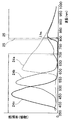
- FIG. 17 shows, in a tabular form, the relationship between a plurality of types of autofluorescent substances contained in a living body, the corresponding excitation wavelength (peak) and fluorescence wavelength (peak).
- the data of FIG. 17 is quoted from “Handbook of Biomedical Fluorescence” from the date of issue: April 16, 2003, editor: by Mary-Ann Mycek (Editor), Brian W. Pogue (Editor).
- collagen I generates autofluorescence having a peak at 400 nm by excitation light having a peak of 325 nm.
- Protoporphyrin generates autofluorescence that peaks at 630 nm and 690 nm by excitation light having a wavelength of 410 nm.
- Many of the autofluorescent materials shown in FIG. 17 have the center (peak) of the spectrum of the autofluorescence wavelength included in the green wavelength band.
- collagen VI and protoporphyrin for example, generate autofluorescence in the red wavelength band although being weak.
- the fluorescence by ICG as a fluorescent agent is imaged using a dichroic prism 61a that transmits red and near-infrared wavelength bands.
- the self-fluorescent substance exists on the shorter wavelength side than the excitation wavelength of 450 nm, the self-fluorescent substance having the possibility of being mixed into the fluorescence of the observation target if the light in the short wavelength band of 450 nm or less in the reference light is cut. The generation of fluorescence can be effectively reduced.
- the wavelength band of the reference light is band-limited so that the reference light obtained by cutting light in the short wavelength band of 450 nm or less is employed.
- This modification basically uses illumination light (reference light) obtained by cutting a short wavelength band of 450 nm or less in the illumination light (reference light) in the blue wavelength band in the fluorescence observation mode in the second embodiment. It becomes the composition to adopt.
- the wavelength for generating the autofluorescence so that the reference light does not include the light in the wavelength band that becomes the excitation light for generating the autofluorescence.
- light with a short wavelength band of 450 nm or less which corresponds to light in the band, is excluded or band-limited from the wavelength band of reference light, only a part of light with a short wavelength band of 450 nm or less is band-limited. May be.
- the fluorescence from the fluorescent agent is imaged by an image sensor set to have sensitivity in the red wavelength band and the near-infrared wavelength band, autofluorescence is generated in the wavelength band in which the image sensor has sensitivity. It is also possible to limit the band (the wavelength band of the reference light) so as not to include light in a wavelength band that generates (the excitation wavelength has a peak). In the case of the autofluorescent material of FIG. 17, the band limitation may be performed so as to exclude at least a wavelength band of 400 nm to 420 nm including, for example, 410 nm (excitation wavelength is a peak) from the wavelength band of the reference light. good.
- the wavelength band of the fluorescence generated by the fluorescent agent administered to the living body or in the vicinity of the wavelength band of the fluorescence You may make it cut the light of the one part wavelength band corresponded to the wavelength band used as the excitation light which generate
- FIG. 18 shows an overall configuration of a fluorescence observation endoscope system 1G according to a second modification of the second embodiment.
- the fluorescence observation endoscope system 1G includes an endoscope 2D in which a television camera 2C is mounted on an optical endoscope 2A, a light source device 3D, a video processor 4B, and a color monitor 5.
- the configuration of the endoscope 2D in which the television camera 2C is mounted on the optical endoscope 2A is the same as that shown in FIGS.
- this modification employs FITC as the fluorescent agent.
- the endoscope 2D includes the excitation light cut filter 25b having the transmission characteristics shown in FIG. 19A.
- the video processor 4B has the same configuration as that of FIG. In this modification, since the image is generated by detecting the fluorescence by FITC, the video processor 4B generates an image signal of G channel that becomes a fluorescent image signal from the signal imaged by the CCD 62b through the dichroic prism 61b. Then, R and B channel image signals to be a reference light image are generated, and a fluorescence image and a two-color reference light image are output to the G, R, and B channels of the color monitor 5, respectively.
- the light source device 3D has an excitation filter 83 disposed on the illumination optical path immediately before the condenser lens 33 in the fluorescence observation mode, and illumination in the normal light observation mode.
- the excitation filter 83 is retracted from the optical path.
- the light source device 3 of FIG. 6 without the excitation filter 83 emits excitation light and reference light having the characteristics shown in FIG. 7 to the light guide 13 side in the fluorescence observation mode.
- the light source device 3D can be configured to have excitation light as light in the first wavelength band having the characteristics shown in FIG.
- the reference light as the light in the second and third wavelength bands is emitted to the light guide 13 side.
- the light having the characteristics shown in FIG. 19 is band-limited by the excitation filter 82 so that the light on the short wavelength band side of 450 nm or less transmits only 420 nm to 430 nm.
- the autofluorescent material shown in FIG. 17 does not include an excitation wavelength (peak) at 420 nm to 430 nm.
- an excitation filter 82 having a characteristic of transmitting 420 to 430 nm of light on the short wavelength side of 450 nm or less is employed.
- the excitation filter 82 has a characteristic of transmitting light having a wavelength longer than 450 nm.
- the excitation filter 82 limits a part of the wavelength band of the reference light (a wavelength band that mainly generates self-fluorescence in the green wavelength band so as to reduce at least self-fluorescence in the green wavelength band).
- the generation of autofluorescence is reduced as in the case of the first modification, the accuracy of fluorescence detection by the fluorescent agent is improved, and the contrast of the fluorescence image by the fluorescent agent is improved. Can do. Therefore, since the surgeon can substantially reduce the mixing of autofluorescence from the image of this modification, it is easy to perform an appropriate diagnosis.
- the light source device 3 in FIG. 2 may be configured such that the excitation filter 81 is disposed as indicated by a dotted line in the fluorescence observation mode.
- the excitation filter 83 may be arranged as indicated by a dotted line.
- FIG. 12A in the case of the fluorescence observation mode also in the light source device 3, three sets of mirror holding devices 72 are selectively arranged on the illumination light path so as to emit illumination light according to the fluorescent agent actually used. Although it is configured, it may be controlled to arrange an excitation filter 81 or the like that limits the band according to each fluorescent agent as indicated by a dotted line. In this case, the mirror switching control circuit 73 may be switched so as to arrange an excitation filter according to the fluorescent agent actually used. In this way, fluorescence observation can be performed using a plurality of types of fluorescent agents, and the autofluorescence can be sufficiently reduced or eliminated from mixing with the fluorescent agent. It can be done properly.
Abstract
Description
例えば、日本国特開2011-167337号公報の従来例は、青色光、緑~黄色の可視光、近赤外光(ICG励起光)とを同時に照射する光源装置と、各色の光の反射光、励起光により発生する蛍光をそれぞれ受光する複数の撮像素子を備えた撮像ユニット、及び撮像ユニットによる信号から表示画像を生成する信号処理装置を開示している。
上記公報の従来例は、該公報中の図13に示すように通常光画像(通常画像)と、1つのICG蛍光画像とをそれぞれ表示する内容と、通常光画像と、2つの異なる蛍光画像の差分演算の画像との画像合成した合成画像とを表示する内容とを開示している。
例えば、輪郭のみでは、色調が異なる脂肪に富む組織と、膜状組織を区別し難くなるために、色調の違いを反映して表示できるようにすることが望まれる。上記の従来例では、通常光画像と蛍光画像の差分演算と合成画像を生成するが、どのようにカラー表示するからの内容を全く開示していないために、臓器や生体組織の輪郭と色調の違いを反映して表示する要請を満たすとは言えない。
本発明は上述した点に鑑みてなされたもので、蛍光画像と、生体組織の輪郭及び色調の違いを反映した画像を生成することができる蛍光観察内視鏡システムを提供することを目的とする。
(第1の実施形態)
図1に示すように本発明の第1の実施形態の蛍光観察内視鏡システム1は、腹部10などの被検体に挿入され、被検体内における生体組織等の被写体の像を撮像して撮像信号として出力する内視鏡2と、内視鏡2に対し、該被写体を照明するための照明光を出射する光源装置3と、内視鏡2に内蔵された撮像部(又は撮像装置)を駆動すると共に、内視鏡2から出力された撮像信号に対して信号処理を行い、画像信号(映像信号)として出力する信号処理装置としてのビデオプロセッサ4と、ビデオプロセッサ4から出力される画像信号に基づき、該被写体の像の画像を表示する、カラー表示装置としてのカラーモニタ5とを備える。
図1に示す内視鏡2は、細長の挿入部6を有する光学内視鏡2Aと、この光学内視鏡2Aの接眼部7に装着され、撮像素子を内蔵したテレビカメラ2Bとから構成される。なお、図1に示す光学内視鏡2Aにテレビカメラ2Bを装着した内視鏡2に限らず、挿入部の先端に撮像素子を配置した電子内視鏡でも良い。
内視鏡2は、例えば患者の腹部10内に挿入される細長の挿入部6と、挿入部6の後端(基端)に設けられた把持部8と、把持部8の後端に設けられた接眼部7とを有する。
光源装置3は、観察モードに応じて後述するように蛍光観察用の照明光と、通常光観察用の照明光を出射(発生)する。光源装置3の照明光は、ライトガイド13及びライトガイド11を経てライトガイド11の先端からさらに照明レンズ15を経て体腔内の患部16(図1参照)等の観察対象となる生体(組織)側に出射される。なお、照明レンズ15は、挿入部6の先端面に設けた照明窓に設けてある。
照明窓に隣接して観察窓が設けてあり、観察窓には、対物レンズ17が配置され、対物レンズ17は、照明された患部16側の被写体側からの光による光学像を結ぶ。
接眼部7には接眼レンズ19が配置され、可視の波長領域の光学像の場合には、接眼レンズ19を介して術者等のユーザは、肉眼で観察することができる。
接眼部7に装着されるテレビカメラ2B内には、結像用レンズ21と、その結像位置に撮像面が配置された撮像部を構成する撮像素子としての例えば電荷結合素子(CCDと略記)22とが設けられている。このCCD22の撮像面の直前には、赤(R)、緑(G)、青(B)の各波長帯域の光をそれぞれ透過する色フィルタとしてのRフィルタ24a、Gフィルタ24b、Bフィルタ24c(図4参照)を備えたモザイクフィルタ24がCCD22の撮像面を形成する各画素単位で配置されている。なお、撮像部(又は撮像装置)は、撮像素子を有するものと定義しても良いし、撮像素子の他に、撮像素子の撮像面に光学像を結像する結像用レンズ21等の光学系を含めたもので定義しても良い。
また、本実施形態においては、上記のように蛍光観察を行うことができるようにCCD22の撮像面よりも入射光側に、(励起光の)照明光を照射した場合における被写体側で反射された反射光が蛍光を受光する画素(本実施形態の場合にはRフィルタ24aを透過した光を受光する画素)に入射するのをカットするカットフィルタとしての励起光カットフィルタ25を配置している。図2においては、例えば結像用レンズ21の前に励起光カットフィルタ25を配置しているが、この位置に限定されるものでない。
このICGは、図4において波長λfm(λfm=805nm)で示す波長において蛍光の強度が極大となる蛍光発生特性を示す。また、波長λfmよりも若干短波長となる波長λex(λex=774nm)で吸収の極大となる特性を示すことが知られている。
このため、本実施形態における励起光カットフィルタ25は、このICGを励起させる励起光の波長帯域の範囲をカットし、波長λfmでピークとなる蛍光の波長帯域を透過するような特性に設定している。図4において、点線で励起光カットフィルタ25による遮光範囲(遮光される波長帯域)を透過率で示す。具体的には、710nm~790nmの波長帯域の光を十分にカットする(例えば殆ど0%に近い透過率で遮光する)。その他の波長帯域では、励起光カットフィルタ25は、大きな透過率で透過する。
図2に示すようにテレビカメラ2Bには、観察モードを切り替える観察モード切替手段として観察モード切替スイッチ(単に切替スイッチとも言う)26が設けてある。テレビカメラ2Bから延出された信号ケーブル27の端部に設けた信号コネクタ28は、ビデオプロセッサ4に着脱自在に接続される。
なお、第2及び第3の波長帯域の光は、図3Aに示すようにG及びBの波長帯域の光に相当し、それぞれG光及びB光とも表す。そして、この蛍光観察モードにおいては、撮像部としてのCCD22は、Rフィルタ24aを透過した光を受光する画素(換言するとRフィルタ24aを備えた画素、さらに簡単化してRフィルタ24aの画素と略記)により、蛍光を撮像し、Gフィルタ24bを透過した光を受光する画素及びBフィルタ24cを透過した光を受光する画素(Gフィルタ24bの画素及びBフィルタ24cの画素と略記)は、G光及びB光の反射光を、(蛍光の画像を補完するための)参照光画像(反射光画像)を生成するために撮像する。
また、切替スイッチ26により通常光観察モードに切り替えられた場合には、光源装置3は、蛍光観察モード時における励起光を出射しないで、第2の波長帯域の光及び第3の波長帯域の光(G光及びB光)と共に、Rの波長帯域の光、つまりR光を出射する。
ダイクロイックミラー32aは、上記のように第2及び第3の波長帯域の光としてのG光及びB光のみを選択的に反射し、G光及びB光よりも長波長の波長帯域の光を選択的に透過する特性を示す。従って、白色LED31aの白色光は、ダイクロイックミラー32aにより帯域制限されて、図3Aにおける400nm~570nmの波長帯域の範囲内の光(ほぼG光及びB光)がライトガイド13側に出射され、さらにライトガイド11を経て被写体側に照射される。
つまり、通常観察モードの場合には、白色LED31a,31bが発光し、可視の波長領域の白色光がライトガイド13の端面に入射される。
また、励起LED31cは、励起光カットフィルタによりカットされるカット波長帯域付近の励起光を発生し、この励起光は励起LED31cに対向する光路上に配置されたダイクロイックミラー32cによりカット波長帯域以内の光のみが選択的に反射されて、反射光路上に配置されたダイクロイックミラー32b、32aを透過し、さらに集光レンズ33を経てライトガイド13の端面に入射される。
発光制御部34は、蛍光観察モードの場合には、白色LED31aと励起LED31cとを同時に発光させて、図3Aに示す波長帯域の照明光を出射させる。
また、発光制御部34は、通常光観察モードの場合には、白色LED31aと白色LED31bとを同時に発光させて、図3Bに示す可視の波長帯域の照明光を出射させる。なお、図2において点線で示すように蛍光観察モードの場合、自家蛍光を発生する励起波長を含む例えば450nm以下の短波長の光をカットする励起フィルタ81又は帯域制限フィルタを照明光路上に配置し、観察対象の蛍光薬剤による蛍光に自家蛍光が混入することを低減するようにしても良い。
一方、蛍光観察モードの場合において、被写体側に図3Aに示すG、Bの波長帯域のG光及びB光と近赤外の波長帯域となる励起光との照明光が照射され、被写体側で反射された反射光、励起光及び蛍光がCCD22に入射される場合、励起光は励起光カットフィルタ25によりカットされ、Rフィルタ24aの画素は、近赤外の波長帯域に属する蛍光の波長帯域の光を受光し、Gフィルタ24bの画素は、Gの波長帯域のG光を受光し、Bフィルタ24aの画素は、Bの波長帯域のB光を受光する。
また、図4示す特性例においては、波長λfmでピークとなるような蛍光を受光する場合、少なくともRフィルタ24aの画素の感度は、Gフィルタ24bの画素及びBフィルタ24cの画素の感度よりも大きいことを示している。なお、本実施形態以外においても、撮像部が単一の撮像素子を用いて構成される場合においては、蛍光を受光するための色フィルタの画素の感度が、蛍光以外の反射光を受光するための色フィルタの画素が蛍光を受光する感度よりも大きくしている。後述する実施形態のように撮像部が3つの撮像素子で構成される場合においては、蛍光を受光するための色フィルタの画素が、蛍光を受光するための第1の撮像素子となり、他の2つの反射光を受光するための色フィルタの画素が第2及び第3の撮像素子に読み替えると同様の関係となる。
図4に示すようにGフィルタ24bの画素とBフィルタ24cの画素が波長λfmの付近においても感度を有する特性になっているが、Rフィルタ24aの画素以外となるこれらの画素も蛍光成分を受光するが、上述したように反射光の強度の方が遥かに蛍光の強度よりも大きい。
図2に示すようにCCD22は信号ケーブル27内の信号線を介してビデオプロセッサ4と接続される。
ビデオプロセッサ4は、CCDドライバ41を有し、CCDドライバ41が発生したCCD駆動信号はCCD22に印加される。CCD22はCCD駆動信号の印加によりCCD22の撮像面に結像された光学像を光電変換した撮像信号を生成し、生成した撮像信号を出力する。CCDの撮像信号は、ビデオプロセッサ4内の信号処理回路42を構成するアンプ43に入力される。なお、信号処理回路42は、図2におけるアンプ43~D/A変換部52により構成される。
プロセス回路44から出力される画像信号は、A/D変換回路45においてアナログの画像信号からデジタルの画像信号に変換された後、AGC回路46に入力され、オートゲイン調整された後、色分離回路47に入力される。色分離回路47は、CCD22のモザイクフィルタ24におけるRフィルタ24a、Gフィルタ24b、Bフィルタ24cの配列に応じた3つの色信号に分離し、3つの色信号を3つの画像信号として出力する。
通常光観察モードにおいては、色分離回路47は、R,G,Bの色信号を画像信号として出力し、蛍光観察モードにおいては、蛍光(F)、G及びBの色信号を画像信号として出力する。図2中では、F(R),G,Bで示している。色分離された3つの画像信号は、ホワイトバランス/蛍光用バランス回路48に入力され、ホワイトバランス又は蛍光用バランスの調整が行われる。
また、蛍光観察モードにおいては、例えば基準となる蛍光観察状態において、F,G及びBの色信号(換言すると蛍光の画像信号、2つの反射光画像の画像信号)の信号レベルが互いに等しくなる蛍光用バランス状態となるように3つのゲインを調整する。
ホワイトバランス/蛍光用バランス回路48を経た3つの画像信号は、ガンマ回路49によりガンマ補正された後、色強調回路50に入力されて色強調される。色強調回路50から出力される3つの画像信号は輪郭強調回路51に入力され、輪郭強調された後、D/A変換部52に入力される。
D/A変換部52は、3つのD/A変換回路52a,52b,52cを備える。D/A変換回路52a,52b,52cは、デジタルの入力信号をそれぞれアナログの出力信号に変換し、変換された3つの画像信号としての蛍光の画像信号(又はRの画像信号)と、G,Bの画像信号とはカラーモニタ5のR,G,Bチャンネルにそれぞれ入力される。
モード判定回路53は、モード判定信号を、ビデオプロセッサ4における信号処理の動作を制御する制御回路54と、調光を行う調光回路55とに出力すると共に、光源装置3の発光制御部34とに出力する。
制御回路54は、切替スイッチ26の操作により設定された観察モードに応じて、ホワイトバランス/蛍光用バランス回路48のゲイン調整動作、色強調回路50,輪郭強調回路51等の動作を制御する。
また、例えば制御回路54は、ゲイン設定値を格納(記憶)する記憶部を構成するメモリ54aを有し、通常光観察モードの場合のホワイトバランス調整を行った場合のアンプ48a~48cのゲイン設定値、蛍光観察モードの場合の蛍光用バランス調整を行った場合のアンプ48a~48cのゲイン設定値を格納する。そして、観察モードの切替が行われた場合、制御回路54は、切り替えられた観察モードにおけるゲイン設定値をメモリ54aから読み出し、アンプ48a~48cのゲインを観察モードに適した状態に設定する。
なお、これらのLEDの発光強度の増減で調光する代わりに、集光レンズ33に至る光路上に絞りを配置し、絞りの開口量を増減して照明光量を調整しても良い。また、複数のLEDの発光強度の増減で調光する場合、絞りの開口量を増減して照明光量を調整する場合と同様に複数のLEDの発光強度の相対的な強度比を一定に保ちながら複数のLEDの発光強度を増減するようにしても良い。
本実施形態においては単一の撮像素子としての1つのCCD22を用いて、蛍光観察と通常光観察とを行うことができるようにしている。
蛍光観察を行うために、最初のステップS1において、初期設定として、ホワイトバランス/蛍光用バランスの設定を行う。基準の被写体を用いて通常光観察モードにおけるホワイトバランス/蛍光用バランス回路48におけるアンプ48a~48cのゲイン調整によるホワイトバランスの設定と、蛍光観察モードにおけるアンプ48a~48cのゲイン調整による蛍光用バランスの設定を行う。それぞれのゲイン設定値はメモリ54aに格納される。なお、以前に行われたホワイトバランスの設定と、蛍光用バランスの設定とのゲイン設定値を利用する場合には、この処理を行うことなく、次のステップS2の処理を行うようにしても良い。
次のステップS2において術者等のユーザは、患部16付近の生体組織にICGの(蛍光観察用)薬剤を投与する。
通常光観察モードに設定された場合、ステップ4に示すように(モード判定信号により)光源装置3は、白色光(可視光)を出射する。また、ステップS5に示すように(モード判定信号により)制御回路54は、ホワイトバランス/蛍光用バランス回路48のゲインをホワイトバランス状態のゲインに設定する。
また、ステップS6に示すようにビデオプロセッサ4(の信号処理回路42)は、白色光の照明のもとで、R,G,Bの色信号を画像信号として生成し、生成したR,G,Bの色信号を通常光画像の画像信号としてカラーモニタ5のR,G,Bのチャンネルに出力する。カラーモニタ5は、通常光画像をR,G,Bでカラー表示する。
一方、切替操作が行われた場合には、ステップS8に示すようにモード判定回路53は、蛍光観察モードに切り替えたモード判定信号を光源装置3(の発光制御部34)とビデオプロセッサ4の制御回路54に送り、光源装置3とビデオプロセッサ4を蛍光観察モードに設定する。
つまり、ステップS9に示すように光源装置3は、蛍光観察モードの照明光を出射する状態、具体的にはG光、B光と近赤外の励起光を出射する状態に設定する。また、ステップS10に示すようにビデオプロセッサ4の制御回路54は、メモリ54aに格納された蛍光観察モードの場合のゲイン設定値を読み出し、ホワイトバランス/蛍光用バランス回路48のアンプ48a~48cのゲインを蛍光用バランス状態のゲインに設定する。具体的には、アンプ48aのゲインをアンプ48b,48cのゲインの数10倍以上に設定する。
ビデオプロセッサ4(の信号処理回路42)は、蛍光画像に対応するRの色信号と、G光,B光による反射光画像に対応するG,Bの色信号とを(画像信号として)生成し、カラーモニタ5のR,G,Bのチャンネルに出力する。そして、ステップS12に示すようにカラーモニタ5は、蛍光画像をR、2つの反射光画像(参照光画像)をG,Bでカラー表示する。
上述したように蛍光画像に対応するRの色信号をG,Bの反射光画像(参照光画像)の色信号よりも少なくとも数10倍以上に増大する調整を行った後、カラーモニタ5のRチャンネルに出力するようにしているので、カラーモニタ5は、蛍光画像と反射光画像(参照光画像)とを(術者が両方の画像を確認し易い状態で)バランス良くカラー表示する。
術者は、蛍光画像及び反射光画像を観察して、患部16に切除すべき部位が存在すると診断した場合には、切除するための処置具を用いる等して切除する処置を行う。
また、ステップS13に示すようにモード判定回路53は、切替スイッチ26による観察モードの切替操作をモニタし、蛍光観察モードから通常光観察モードに切り替える切替操作が行われたか否かを判定する。
一方、切替操作が行われない場合には、次のステップS14における観察終了の指示操作が行われたか否かを判定し、観察終了の指示操作が行われない場合には蛍光観察モードの状態を維持し、ステップS9の処理に戻る。
このように動作する本実施形態によれば、蛍光画像と、可視領域における互いに異なる2つの波長帯域の反射光画像とを互いに異なる色でカラー表示することにより、蛍光画像と、生体組織の輪郭及び色調の違いを反映した画像を生成することができる。また、術者に対して、診断や処置等を円滑に行い易い画像を提供できる。
次に第1の実施形態の第1変形例を説明する。
上述した説明においては、薬剤としてICGを用いた場合で説明したが、フルオレセイン(FITCと略記)を用いても良い。FITCは、波長λfm(λfm=521nm)において蛍光を放射する強度が極大となる蛍光発生特性を示すことが知られている。図8において波長λfmを示している。また、波長λfmよりも短波長側となる波長λex(λex=494nm)で吸収の極大となる特性を示すことが知られている。
ダイクロイックミラー32dは、図7に示す第2の波長帯域となる例えば630nm~670nmの光と、第3の波長帯域となる例えば400nm~420nmの光とを選択的に反射し、他の波長帯域の光を選択的に透過する。
また、ダイクロイックミラー32eは、例えば白色LEDにより構成される励起光源31dの白色光の入射に対して、ダイクロイックミラー32dの選択的な透過特性を反射特性に置換し、その他の波長を選択的に透過する特性を有する。換言すると、2つの白色LED31a,31bを同時に発光させた場合、第1の実施形態の場合と同様に400nm~700nmの可視の波長帯域の白色光が集光レンズ33により集光されてライトガイド13に入射される。図7において白色LED31a,31bを同時に発光させた場合における光源装置3が出射する照明光の波長帯域の範囲を点線で示す。
発光制御部34は、第1の実施形態の場合とほぼ同様に、蛍光観察モードの場合には白色LED31aと励起光源31dとを同時に発光させ、通常観察モードの場合には白色LED31aと31bとを同時に発光させるように制御する。なお、図6において点線で示すように蛍光観察モードの場合、自家蛍光を発生する励起波長を含む例えば420nm~430nmの光をカットする励起フィルタ83又は帯域制限フィルタを照明光路上に配置し、観察対象の蛍光薬剤による蛍光に自家蛍光が混入することを低減するようにしても良い。
励起光カットフィルタ25bは、図8において点線で示すように励起光の波長帯域の光をカットするように遮光特性が設定されている。具体的には上記励起光の波長帯域としての450nm~500nmの光を確実に遮光するように長波長側及び短波長側にそれぞれ10nmのマージンを含めた例えば440nm~510nmの光を遮光する特性(透過率が殆ど0となる特性)に設定している。なお、フィルタの作成時のバラツキを殆ど0にできる場合には、励起光カットフィルタ25bの遮光する範囲を、450nm~500nmの範囲に設定しても良い。
第1の実施形態においては、Rフィルタが蛍光を受光するように設定していたが、本変形例においてはGフィルタが、蛍光を受光するように設定している。そのため、ビデオプロセッサ4は、Gフィルタの画素から出力される信号を蛍光の画像信号として処理する。そして、カラーモニタ5において、蛍光の画像信号をGのチャンネルに割り当てて、他のR,Bのチャンネルに割り当てられた参照光による画像とをカラー表示する。その他は、第1の実施形態と同様の構成である。
次に本変形例の動作を説明する。通常光観察モードに設定された場合には、光源装置3は、図7の点線で示す400nm~700nmの可視の波長帯域の照明光を出射する。そして、この照明光で患部16等を照明し、CCD22により撮像する。
一方、蛍光観察モードに設定した場合には、光源装置3の発光制御部34は、白色LEd31aと励起LED31cとを発光させ、光源装置3は、図7の実線で示す照明光を出射する。つまり、Rの波長帯域の光(R光)とBの波長帯域の光(B光)からなる参照光と、Gの波長帯域の励起光とをライトガイド13側に出射し、生体にはこれらの照明光が照射される。
ビデオプロセッサ4は、第1の実施形態におけるRフィルタ24aの画素をGフィルタ24bの画素に読み替え、かつGフィルタ24bの画素をRフィルタ24aの画素に読み替え、かつRチャンネルをGチャンネルに、GチャンネルをRチャンネルに読み替えた動作となる。本変形例によれば、第1の実施形態と殆ど同じ効果が得られる。
次に第1の実施形態における第2変形例を説明する。本変形例は、生体に投与する薬剤として5アミノレブリン酸(5-ALAと略記)を用いて蛍光観察を行う。5-ALAは、波長λfm(λfm=635nm)において蛍光を放射する強度が極大となる蛍光発生特性を示すことが知られている。図11において波長λfmを示している。
本変形例は、図2の蛍光観察内視鏡システム1において光源装置3におけるダイクロイックミラー32a,32b,32cをダイクロイックミラー32g,32h,32iに変更すると共に、励起光源31cを励起光源31eに変更した構成にし、また、図2におけるテレビカメラ2B内に配置した励起光カットフィルタ25を設けない構成にしている。
白色LED31a及びダイクロイックミラー32gは、400nm~550nmの参照光を発生する。つまり、第1の実施形態におけるダイクロイックミラー32aが、400nm~570nmの参照光を、400nm~550nmに僅かに変更している。
また、 励起LED31e及びダイクロイックミラー32iは、380nm~400nm(又は380nm~440nm)の励起光を発生する。励起LED31eは、380nm~400nm(又は380nm~440nm)をカバーする光を発生するLED光源により構成され、ダイクロイックミラー32iは、380nm~400nm(又は380nm~440nm)の波長帯域の光を選択的に反射し、ダイクロイックミラー32h側に導光する。
ダイクロイックミラー32iにより選択的に反射された光は、ダイクロイックミラー32hを透過し、さらにダイクロイックミラー32gを少なくとも380nm~400nmの光が透過して、さらに集光レレンズ33によりライトガイド13の端面に入射される。
この場合、白色LED31aと励起光源31eとが同時に発光することにより、光源装置3は400nm~550nmのG光及びB光と、380nm~440nmの励起光とを同時に発生してライトガイド13側に出射する。なお、図10における400nm~440nmの波長帯域の光は、励起光と参照光の照明とに共通して使用される。
また、通常光観察モードの場合には、図10における点線で示すように光源装置3は、400nm~700nmの白色光をライトガイド13側に出射する。
本変形例においては、通常光観察モードの場合には、第1の実施形態と殆ど同様の構成となり、蛍光観察モードにおいては、第1の実施形態の励起光の波長帯域がR光の短波長側ないし紫外付近に設定した場合に相当し、かつその場合の蛍光を第1の実施形態の場合と同様にRフィルタを用いて受光する。
このため、本変形例における撮像部としてのCCD22は、通常光観察モード及び蛍光観察モードにいずれにおいても、図11に示すように(図4の点線で示す励起光カットフィルタ25を用いることなく)実線で示すR,G,Bフィルタを用いて受光(撮像)する。その他の構成は図2の場合と同様である。
次に、本実施形態の動作を説明する。通常観察モードの場合には、第1の実施形態と殆ど同様の動作となる。
一方、蛍光観察モードの場合には、光源装置3は、400nm~550nmの波長帯域の参照光(G光、B光)を出射すると共に、380nm~440nmの波長帯域の励起光とを照明光として出射する。撮像部を構成するCCD22は、G,Bフィルタの画素が参照光の反射光を受光してG,Bの撮像信号を生成し、Rフィルタの画素が蛍光を受光して蛍光の撮像信号を生成する。
本変形例によれば、励起光カットフィルタを用いることなく、第1の実施形態と殆ど同様の効果を得ることができる。
上述の説明においては、薬剤が異なる場合に対応した第1の実施形態の蛍光観察内視鏡システム1、1B、1Cを説明したが、異なる薬剤を用いた場合に対応できる光源装置及び信号処理装置としてのビデオプロセッサを備えた図12Aに示す第3変形例の蛍光観察内視鏡システム1Dにしても良い。
図12Aに示す蛍光観察内視鏡システム1Dにおいては、図2,図6、図9の内視鏡には、それぞれ固有の内視鏡であることを示す識別情報(IDと略記)を発生するID発生回路71(図12A中では単にIDと略記)を、例えば信号コネクタ28内に備える。IDは、固有の内視鏡がそれぞれ備える各薬剤に応じた撮像部の光学特性に対応した情報を含む。また、ビデオプロセッサ4は、信号コネクタ28が接続された場合に、内視鏡2のIDを識別するID識別回路54bを例えば制御回路54が備える。なお、ID識別回路54bを制御回路54の外部に設け、識別したIDを制御回路54に出力するようにしても良い。
また、図12Aに示す光源装置は、励起光源として赤外の波長帯域と共に可視の波長帯域の光を発生する励起光源31c′を用いている。なお、3組のミラー保持装置72は、例えばモータの回転軸に3枚の回転板を取り付け、3枚の回転板上に、回転角が120度間隔で3つのダイクロイックミラーをそれぞれ取り付け、モータの回転角を120度単位で回転させることにより、3組の内の1組のダイクロイックミラーを照明光路上に配置できるようにしている。
制御回路54は、識別したIDに応じて、ミラー切替制御回路73がIDの内視鏡(より具体的には使用する薬剤に対応した励起光カットフィルタ25,25b、又は励起光カットフィルタを設けていない内視鏡)に対応したダイクロイックミラーを光路上に配置するように制御する。つまり、制御手段としての制御回路54は、識別したIDに応じて、光源装置3が出射する照明光を制御すると共に、ビデオプロセッサ4(の信号処理回路42)の信号処理の動作を制御する。
図12Aに示す内視鏡2の代わりに図6の(FITCの薬剤に対応した撮像部を備えた)内視鏡2がビデオプロセッサ4に接続された場合には、制御回路54は図6のダイクロイックミラー32d,32e,32fが配置されるようにミラー保持装置72の動作を制御する。
また、図12Aに示す内視鏡2の代わりに図9の(5-ALAの薬剤に対応した撮像部を備えた)内視鏡2がビデオプロセッサ4に接続された場合には、制御回路54は図9のダイクロイックミラー32g,32h,32iが配置されるようにミラー保持装置72の動作を制御する。
図12Aに示す内視鏡2がビデオプロセッサ4に接続された場合には、第1の実施形態で説明した動作となり、第1の実施形態の効果を有する。また、図6の内視鏡2がビデオプロセッサ4に接続された場合には、第1変形例の動作となり、第1変形例の効果を有する。また、図9の内視鏡2がビデオプロセッサ4に接続された場合には、第2変形例の動作となり、第2変形例の効果を有する。本変形例によれば、第1の実施形態、第1変形例、第2変形例の効果を有すると共に、異なる薬剤を用いて蛍光観察を行う場合にも共通の光源装置3,共通のビデオプロセッサ4で対応できる。
また、モータ74は、(ビデオプロセッサ4の)モード判定回路53から出力されるモード切替信号により回転し、フィルタターレット72Cのフィルタ72a又は72bの一方を照明光路上に配置する。図12Bの状態は、通常光観察モードが設定された状態であり、第1フィルタ72aは、図3Bに示すような白色光の波長帯域の光を透過させるように透過特性が設定される。これに対して、蛍光観察モードに切り替える操作を行った場合には、モータ74によりフィルタターレット72Cが回転し、第2フィルタ72bが照明光路上に配置される。第2フィルタ72bは、図3Aに示す波長帯域の光を透過するように設定されたバンドパスフィルタの透過特性を有する。なお、本変形例においては、観察モードが切り替えられた場合においても、光源としてのキセノンランプ71Bは、常時発光(点灯)した状態を維持し、発光のON/OFFは行わない。
また、図12Bの図示例では、光源装置3Bは、発光量を調整して照明光量を調整する機能を設けてないので、ビデオプロセッサ4の調光回路55は不必要となる。図12Bの構成において、ビデオプロセッサ4の調光信号を点灯回路73Bに入力し、調光信号に基づいて、点灯回路73Bから出力される点灯電源の電力を調整することによりキセノンランプ71Bの発光量を制御して照明光量を調整するようにしても良い。なお、第2フィルタ72bの透過特性が異なるように設定したフィルタターレット72Cを用いるようにすれば、図12Bに示す光源装置3Bを第1の実施形態以外の光源装置にも適用できる。
上述した実施形態及び変形例においては、単一の撮像素子としてのCCD22を用いて蛍光観察を行う蛍光観察内視鏡システムを説明したが、以下に説明するように撮像部を3つの撮像素子を用いて構成しても良い。
図13は第2の実施形態の蛍光観察内視鏡システム1Eを示す。この蛍光観察内視鏡システム1Eは、例えば図2に示す蛍光観察内視鏡システム1において、光学内視鏡2Aに装着したテレビカメラ2Bの代わりに、3つのCCDを内蔵したテレビカメラ2Cを装着した内視鏡2Dを用い、1つの入力信号に対する信号処理を行うビデオプロセッサ4の代わりに、3つのチャンネルの入力信号に対する信号処理を行うビデオプロセッサ4Bを採用している。なお、光源装置3は、第1の実施形態の光源装置3と同じ構成である。
テレビカメラ2Cは、(点線で示す)接眼窓に対向して図4に示す特性の励起光カットフィルタ25が配置され、また結像用レンズ21に対向する光路上に3つのダイクロイックプリズム61c,61a,61bと、ダイクロイックプリズム61c,61a,61bにおける出射面にそれぞれ取り付けられたCCD62c,62a,62bとが配置されて3板式の撮像部63が形成されている。
上記ダイクロイックプリズム61a,61b,61cは、例えば図14に示すような特性を有する。ダイクロイックプリズム61aは、R及び赤外の波長帯域の光を透過(してその出射面に配置されたCCD62aが受光)する特性を有し、ダイクロイックプリズム61bは、Gの波長帯域の光を透過(してその出射面に配置されたCCD62bが受光)する特性を有し、ダイクロイックプリズム61cは、Bの波長帯域の光を透過(してその出射面に配置されたCCD62cが受光)する特性を有するように設定されている。
また、ダイクロイックプリズム61bとの接合面において選択的に透過したG光は、その出射面に配置されたCCD62bで受光される。
このため、第1の実施形態においても、図14に示すような特性を有するR,G,Bフィルタを有するモザイクフィルタ24を用いるようにしても良い。
なお、CCD62k(k=a,b,c)として、ダイクロイックプリズム61kを透過した光を受光する撮像素子と定義した場合には、図14の縦軸は感度を表すことになる。また、図14に示す特性で蛍光観察等を行うと、蛍光を透過するダイクロイックプリズムは、61aのみとなり、ダイクロイックプリズム61aを透過した光を受光するCCD62aのみが、より好ましい状態で蛍光を受光することになる。
入力端65a、65b,65cにそれぞれ入力された入力信号は、それぞれ信号処理系42a,42b,42cにより信号処理されて、カラーモニタ5のR,G,Bチャンネルに出力される。なお、信号処理系42a,42b,42cは、以下の説明するようにアンプ43a~AGC回路46a,アンプ48a~D/A変換回路52a、アンプ43b~AGC回路46b,アンプ48b~D/A変換回路52b、アンプ43c~AGC回路46c,アンプ48c~D/A変換回路52cにより構成される。
入力端65bに入力されるCCD62Bの撮像信号は、上記アンプ43a~AGC回路46a,アンプ48a~D/A変換回路52aにおけるaをbに置換した各回路(つまり、アンプ43b~AGC回路46b,アンプ48b~D/A変換回路52b)を経て、カラーモニタ5のGチャンネルにGの画像信号として出力される。
また、入力端65bに入力されるCCD62Bの撮像信号は、上記アンプ43a~AGC回路46a,アンプ48a~D/A変換回路52aにおけるaをcに置換した各回路(つまり、アンプ43c~AGC回路46c,アンプ48c~D/A変換回路52c)を経て、カラーモニタ5のBチャンネルにBの画像信号として出力される。その他の構成は、図2の蛍光観察内視鏡システム1とほぼ同様の構成である。
本実施形態の場合、(観察モードの切替に依存せずに又はいずれの観察モードの場合においても)第1の撮像素子としてのCCD62aはRチャンネル、第2及び第3の撮像素子としてのCCD62b,62cは、G、Bチャンネルにそれぞれ入力される。特に蛍光観察モードの場合において、第1の実施形態(段落0033)において説明したように第1の撮像素子、第2及び第3の撮像素子の出力信号を入力するチャンネルを上記の場合とは異なり、少なくともそれぞれ異なるチャンネルに入力するようにしても良い。また、蛍光観察モードの場合においてのみ、通常光観察モードの場合において設定された組み合わせのチャンネル(第1~第3撮像素子の出力信号に対してそれぞれ組み合わされるR,G,Bチャンネル)と異なる組み合わせのチャンネルに設定するようにしても良い。
但し、第1の実施形態においては、ビデオプロセッサ4は、色分離回路47において、蛍光(R),G,Bの画像信号に分離していたが、本実施形態においては、撮像部63が3つの撮像信号としての蛍光(R),G,Bの撮像信号を出力する構成となっている。そのため、蛍光(R),G,Bの撮像信号を、ビデオプロセッサ4Bの3つの信号処理系42a,42b,42cにそれぞれ入力させるようにしており、ビデオプロセッサ4Bは色分離を行わない。本実施形態は、第1の実施形態とほぼ同様の効果を有する。
次に第2の実施形態の変形例を説明する。以下の変形例は、生体に投与される蛍光薬剤による観察対象となる蛍光(画像)に対して、自家蛍光による影響を低減する蛍光観察内視鏡システムを提供するものとなる。
Claims (18)
- 生体に投与した薬剤に照射することで蛍光を発光させる第1の波長帯域の光と、可視光であって前記第1の波長帯域の光と異なる波長帯域の第2の波長帯域の光と、可視光であって前記第1及び第2の波長帯域の光と異なる波長帯域の第3の波長帯域の光と、を同時に出射可能な光源装置と、
前記蛍光と、前記第2及び第3の波長帯域の光の反射光とを同時に受光する撮像素子を有するよう構成された撮像部と、
前記撮像部が取得した前記蛍光の撮像信号と、前記第2及び第3の波長帯域の光の反射光から取得した第2及び第3の撮像信号とから、それぞれ異なる色で表示するカラー表示画像を生成する画像処理を行う信号処理装置と、
を備えることを特徴とする蛍光観察内視鏡システム。 - 前記撮像部は、前記撮像素子として単一の撮像素子のみを具備して構成されることを特徴とする請求項1に記載の蛍光観察内視鏡システム。
- 前記撮像部は、前記撮像素子として、前記蛍光を受光する第1の撮像素子と、前記第2の波長帯域の光の反射光を受光する第2の撮像素子と、前記第3の波長帯域の光の反射光を受光する第3の撮像素子と、を具備して構成されることを特徴とする請求項1に記載の蛍光観察内視鏡システム。
- 前記撮像部は、前記第1の撮像素子として、前記第2及び第3の波長帯域の光を受光する場合の感度よりも、前記蛍光の波長帯域の光に対する感度の方が大きくなるように設定されたものを備えることを特徴とする請求項3に記載の蛍光観察内視鏡システム。
- 前記撮像部は、前記単一の撮像素子として、前記第2及び第3の波長帯域の光を受光する場合の感度よりも、前記蛍光の波長帯域の光に対する感度の方が大きくなるように設定されたものを備えることを特徴とする請求項2に記載の蛍光観察内視鏡システム。
- 前記撮像部は、前記単一の撮像素子として、前記第2及び第3の波長帯域よりも長波長側にある前記蛍光を受光するように設定されたものを備えることを特徴とする請求項2に記載の蛍光観察内視鏡システム。
- 前記撮像部は、前記第2及び第3の撮像素子として、前記蛍光に対する感度が前記第1の撮像素子よりも低くなるように設定されたものを備えることを特徴とする請求項3に記載の蛍光観察内視鏡システム。
- 前記撮像部は、前記第1の撮像素子として、前記第2及び第3の波長帯域よりも長波長側にある前記蛍光を受光するように設定されたものを備えることを特徴とする請求項3に記載の蛍光観察内視鏡システム。
- 前記光源装置は、前記第1から前記第3の波長帯域の光に換えて、白色光を出射可能であり、前記信号処理装置は、R,G,Bチャンネルにそれぞれ入力される信号からR,G,Bの色信号を生成して、カラー表示装置に出力する信号処理を行い、
前記第1の撮像素子の撮像信号は前記Rチャンネル、前記第2及び第3の撮像素子の各撮像信号は、前記G、Bチャンネルにそれぞれ入力されることを特徴とする請求項3に記載の蛍光観察内視鏡システム。 - 前記生体に投与される複数種類の薬剤に応じて、前記光源装置は、前記第1の波長帯域がそれぞれ異なる励起光と、前記第2及び第3の波長帯域の光からなる照明光を出射可能であり、
かつ前記信号処理装置は、前記生体に投与される複数種類の薬剤に応じた前記照明光に対応して前記撮像素子が取得する前記蛍光の撮像信号と、前記第2及び第3の撮像信号に対する信号処理を行い、それぞれ異なる3つの色で表示するカラー表示画像を生成することを特徴とする請求項2に記載の蛍光観察内視鏡システム。 - 前記信号処理装置は、前記蛍光の撮像信号に対する信号レベルを、前記第2及び第3の撮像信号の信号レベルよりも数10倍以上のゲインに調整するゲイン調整回路を備えることを特徴とする請求項10に記載の蛍光観察内視鏡システム。
- 前記光源装置が前記第1から前記第3の波長帯域の光を出射して、前記信号処理装置が前記撮像部から出力される前記蛍光の撮像信号と、前記第2及び第3の撮像信号とからそれぞれ異なる3色で表示するカラ-表示画像を生成する処理を行う蛍光観察モードと、
前記光源装置が前記第1から前記第3の波長帯域の光の代わりに白色光を出射して、前記信号処理装置が前記撮像部から出力される赤、緑、青の3つの波長帯域の撮像信号に対してそれぞれ異なる3色で表示するカラ-表示画像を生成する処理を行う通常光観察モードとを切り替える操作を行うモード切替スイッチを有することを特徴とする請求項11に記載の蛍光観察内視鏡システム。 - 前記光源装置は、前記第1から前記第3の波長帯域の光に換えて、白色光を出射可能であり、前記信号処理装置は、R,G,Bチャンネルにそれぞれ入力される信号からR,G,Bの色信号を生成して、カラー表示装置に出力する信号処理を行い、
前記第1の撮像素子、前記第2及び第3の撮像素子の各撮像信号は、前記R,G、Bチャンネルにおける互いに異なるチャンネルにそれぞれ入力されることを特徴とする請求項3に記載の蛍光観察内視鏡システム。 - 更に、前記光源装置は、前記第2の波長帯域の光又は前記第3の波長帯域の光において、前記生体に含まれる自家蛍光物質が自家蛍光を発生させる励起光となる波長帯域に相当する一部の波長帯域の光をカットする帯域制限装置を備えることを特徴とする請求項1に記載の蛍光観察内視鏡システム。
- 前記帯域制限装置は、前記第2の波長帯域の光又は前記第3の波長帯域の光における少なくとも450nm以下の短波長帯域における一部の波長帯域の光の透過をカットする帯域制限フィルタにより構成されることを特徴とする請求項14に記載の蛍光観察内視鏡システム。
- 前記帯域制限装置は、前記第2の波長帯域の光又は前記第3の波長帯域の光において、前記生体に投与された前記薬剤が発生する蛍光の波長帯域内又は当該蛍光の波長帯域の近傍に、前記自家蛍光を発生させる励起光となる波長帯域に相当する一部の波長帯域の光をカットすることを特徴とする請求項14に記載の蛍光観察内視鏡システム。
- 更に、前記光源装置は、前記第2の波長帯域の光又は前記第3の波長帯域の光において、前記生体に含まれる自家蛍光物質が自家蛍光を発生させる励起光となる波長帯域に相当する一部の波長帯域をカットする帯域制限装置と、
前記モード切替スイッチにより前記蛍光観察モードに切り替えられた場合には前記帯域制限装置を照明光路上に配置し、前記通常光観察モードに切り替えられた場合には前記帯域制限装置を照明光路から退避させるように制御する制御装置と、
を備えることを特徴とする請求項12に記載の蛍光観察内視鏡システム。 - 前記光源装置は、前記生体に投与される前記薬剤として、種類が異なる第1の薬剤と第2の薬剤にそれぞれ対応して励起させる波長帯域が異なる第1の励起光と、第2の励起光とを、前記第1の波長帯域の光として選択的に出射可能であると共に、
前記第2の波長帯域の光又は前記第3の波長帯域の光において、前記生体に実際に投与された前記第1の薬剤又は前記第2の薬剤が発生する前記蛍光の波長帯域内又は当該蛍光の波長帯域の近傍に、前記生体に含まれる自家蛍光物質が発生する自家蛍光を発生させる励起光となる波長帯域に相当する一部の波長帯域をカットする帯域制限装置を備えることを特徴とする請求項1に記載の蛍光観察内視鏡システム。
Priority Applications (4)
| Application Number | Priority Date | Filing Date | Title |
|---|---|---|---|
| EP15776796.3A EP3111822A4 (en) | 2014-04-08 | 2015-03-27 | Fluorescence endoscopy system |
| CN201580017517.4A CN106132276B (zh) | 2014-04-08 | 2015-03-27 | 荧光观察内窥镜系统 |
| JP2015556283A JP6005303B2 (ja) | 2014-04-08 | 2015-03-27 | 蛍光観察内視鏡システム |
| US15/284,655 US20170020377A1 (en) | 2014-04-08 | 2016-10-04 | Fluorescence observation endoscope system |
Applications Claiming Priority (2)
| Application Number | Priority Date | Filing Date | Title |
|---|---|---|---|
| JP2014079764 | 2014-04-08 | ||
| JP2014-079764 | 2014-04-08 |
Related Child Applications (1)
| Application Number | Title | Priority Date | Filing Date |
|---|---|---|---|
| US15/284,655 Continuation US20170020377A1 (en) | 2014-04-08 | 2016-10-04 | Fluorescence observation endoscope system |
Publications (1)
| Publication Number | Publication Date |
|---|---|
| WO2015156153A1 true WO2015156153A1 (ja) | 2015-10-15 |
Family
ID=54287730
Family Applications (1)
| Application Number | Title | Priority Date | Filing Date |
|---|---|---|---|
| PCT/JP2015/059654 WO2015156153A1 (ja) | 2014-04-08 | 2015-03-27 | 蛍光観察内視鏡システム |
Country Status (5)
| Country | Link |
|---|---|
| US (1) | US20170020377A1 (ja) |
| EP (1) | EP3111822A4 (ja) |
| JP (2) | JP6005303B2 (ja) |
| CN (1) | CN106132276B (ja) |
| WO (1) | WO2015156153A1 (ja) |
Cited By (6)
| Publication number | Priority date | Publication date | Assignee | Title |
|---|---|---|---|---|
| WO2017068908A1 (ja) * | 2015-10-22 | 2017-04-27 | オリンパス株式会社 | 内視鏡システム |
| JPWO2017077882A1 (ja) * | 2015-11-04 | 2017-11-02 | オリンパス株式会社 | 画像処理装置、及び内視鏡システム |
| JP2018089109A (ja) * | 2016-12-02 | 2018-06-14 | 富士フイルム株式会社 | 内視鏡装置及び内視鏡装置の作動方法 |
| WO2019044802A1 (ja) * | 2017-08-28 | 2019-03-07 | Hoya株式会社 | 内視鏡用光源装置及び内視鏡システム |
| CN112005546A (zh) * | 2018-03-23 | 2020-11-27 | 索尼公司 | 信号处理设备、信号处理方法、图像捕获设备以及医用图像捕获设备 |
| RU2772543C1 (ru) * | 2021-06-23 | 2022-05-23 | Федеральное государственное бюджетное военное образовательное учреждение высшего образования "Военно-медицинская академия имени С.М. Кирова" Министерства обороны Российской Федерации (ВМедА) | Способ оценки состояния местных лоскутов в полости носа с помощью аутофлюоресцентной эндоскопии после внутриносовых хирургических вмешательств |
Families Citing this family (16)
| Publication number | Priority date | Publication date | Assignee | Title |
|---|---|---|---|---|
| WO2016189892A1 (ja) | 2015-05-28 | 2016-12-01 | オリンパス株式会社 | 光源装置 |
| WO2017018126A1 (ja) * | 2015-07-30 | 2017-02-02 | オリンパス株式会社 | 内視鏡用カメラヘッド及びこれを有する内視鏡装置 |
| NL2018494B1 (en) | 2017-03-09 | 2018-09-21 | Quest Photonic Devices B V | Method and apparatus using a medical imaging head for fluorescent imaging |
| US20200405135A1 (en) | 2018-03-15 | 2020-12-31 | Sony Olympus Medical Solutions Inc. | Medical observation system |
| JP2019185002A (ja) * | 2018-04-11 | 2019-10-24 | ソニー株式会社 | 顕微鏡システム及び医療用光源装置 |
| JP6467746B1 (ja) * | 2018-04-20 | 2019-02-13 | パナソニックIpマネジメント株式会社 | 内視鏡システムおよび内視鏡システムの作動方法 |
| JP7163386B2 (ja) * | 2018-06-19 | 2022-10-31 | オリンパス株式会社 | 内視鏡装置、内視鏡装置の作動方法及び内視鏡装置の作動プログラム |
| JP6978604B2 (ja) * | 2018-07-10 | 2021-12-08 | オリンパス株式会社 | 内視鏡装置、内視鏡装置の作動方法及びプログラム |
| EP3667299B1 (en) * | 2018-12-13 | 2022-11-09 | Imec VZW | Multimodal imaging system |
| JP7224963B2 (ja) * | 2019-03-01 | 2023-02-20 | ソニー・オリンパスメディカルソリューションズ株式会社 | 医療用制御装置及び医療用観察システム |
| JP7374600B2 (ja) * | 2019-03-22 | 2023-11-07 | ソニー・オリンパスメディカルソリューションズ株式会社 | 医療用画像処理装置及び医療用観察システム |
| EP3979893A4 (en) * | 2019-06-07 | 2023-06-28 | The Board of Trustees of the Leland Stanford Junior University | Optical systems and methods for intraoperative detection of csf leaks |
| CN114051723A (zh) * | 2019-07-09 | 2022-02-15 | 富士胶片富山化学株式会社 | 图像生成装置、药剂识别装置、药剂显示装置、图像生成方法以及程序 |
| KR102372603B1 (ko) * | 2019-10-30 | 2022-03-08 | 한국전기연구원 | 기능영상 제공 의료 시스템 |
| JPWO2021186803A1 (ja) * | 2020-03-19 | 2021-09-23 | ||
| US11599999B2 (en) * | 2021-02-03 | 2023-03-07 | Verily Life Sciences Llc | Apparatus, system, and method for fluorescence imaging with stray light reduction |
Citations (4)
| Publication number | Priority date | Publication date | Assignee | Title |
|---|---|---|---|---|
| JP2006263044A (ja) * | 2005-03-23 | 2006-10-05 | Fuji Photo Film Co Ltd | 蛍光検出システム |
| JP2007252635A (ja) * | 2006-03-23 | 2007-10-04 | Olympus Medical Systems Corp | 画像処理装置 |
| JP2011167337A (ja) * | 2010-02-18 | 2011-09-01 | Fujifilm Corp | 画像取得方法および画像撮像装置 |
| JP2012130506A (ja) * | 2010-12-21 | 2012-07-12 | Fujifilm Corp | 光計測システムおよび光計測方法 |
Family Cites Families (27)
| Publication number | Priority date | Publication date | Assignee | Title |
|---|---|---|---|---|
| US5590660A (en) * | 1994-03-28 | 1997-01-07 | Xillix Technologies Corp. | Apparatus and method for imaging diseased tissue using integrated autofluorescence |
| US7172553B2 (en) * | 2001-05-16 | 2007-02-06 | Olympus Corporation | Endoscope system using normal light and fluorescence |
| US6899675B2 (en) * | 2002-01-15 | 2005-05-31 | Xillix Technologies Corp. | Fluorescence endoscopy video systems with no moving parts in the camera |
| US20040225222A1 (en) * | 2003-05-08 | 2004-11-11 | Haishan Zeng | Real-time contemporaneous multimodal imaging and spectroscopy uses thereof |
| JP4139276B2 (ja) * | 2003-06-17 | 2008-08-27 | オリンパス株式会社 | 電子内視鏡装置及び信号処理装置 |
| US20060173358A1 (en) * | 2005-01-11 | 2006-08-03 | Olympus Corporation | Fluorescence observation endoscope apparatus and fluorescence observation method |
| RU2381737C2 (ru) * | 2005-05-12 | 2010-02-20 | Олимпус Медикал Системз Корп. | Устройство для наблюдения биологических объектов |
| EP1889563B1 (en) * | 2005-06-08 | 2015-07-29 | Olympus Medical Systems Corp. | Endoscope and image processing device |
| JP4954858B2 (ja) * | 2007-11-30 | 2012-06-20 | オリンパス株式会社 | 蛍光観察装置および内視鏡装置 |
| JP5231625B2 (ja) * | 2008-03-18 | 2013-07-10 | ノヴァダク テクノロジーズ インコーポレイテッド | Nir画像およびフルカラー画像を獲得するための画像化システムおよびその作動方法 |
| US20090236541A1 (en) * | 2008-03-24 | 2009-09-24 | General Electric Company | System and Methods for Optical Imaging |
| US8810631B2 (en) * | 2008-04-26 | 2014-08-19 | Intuitive Surgical Operations, Inc. | Augmented stereoscopic visualization for a surgical robot using a captured visible image combined with a fluorescence image and a captured visible image |
| JP5396121B2 (ja) * | 2009-03-26 | 2014-01-22 | オリンパス株式会社 | 画像処理装置、撮像装置、画像処理プログラムおよび画像処理装置の作動方法 |
| JP4689767B2 (ja) * | 2009-04-21 | 2011-05-25 | オリンパスメディカルシステムズ株式会社 | 蛍光画像装置および蛍光画像装置の作動方法 |
| US20110071403A1 (en) * | 2009-09-21 | 2011-03-24 | Board Of Regents Of The University Of Texas System | Functional near-infrared fluorescence lymphatic mapping for diagnosing, accessing, monitoring and directing therapy of lymphatic disorders |
| BR112012023287A2 (pt) * | 2010-03-17 | 2017-03-21 | Zeng Haishan | aparelho e método para geração de imagem multiespectral, e, método para quantificação de informação fisiológica e morfológica de tecido |
| CN103140157B (zh) * | 2011-03-15 | 2014-10-01 | 奥林巴斯医疗株式会社 | 医疗装置 |
| JP2012217673A (ja) * | 2011-04-11 | 2012-11-12 | Fujifilm Corp | 内視鏡診断装置 |
| EP2581030B1 (en) * | 2011-04-11 | 2015-04-29 | Olympus Medical Systems Corp. | Endoscope apparatus |
| JP5926909B2 (ja) * | 2011-09-07 | 2016-05-25 | オリンパス株式会社 | 蛍光観察装置 |
| WO2013115323A1 (ja) * | 2012-01-31 | 2013-08-08 | オリンパス株式会社 | 生体観察装置 |
| US9407838B2 (en) * | 2013-04-23 | 2016-08-02 | Cedars-Sinai Medical Center | Systems and methods for recording simultaneously visible light image and infrared light image from fluorophores |
| JP5931031B2 (ja) * | 2013-09-23 | 2016-06-08 | 富士フイルム株式会社 | 内視鏡システム及び内視鏡システムの作動方法 |
| JP5925169B2 (ja) * | 2013-09-27 | 2016-05-25 | 富士フイルム株式会社 | 内視鏡システム及びその作動方法並びに内視鏡用光源装置 |
| DE102013111368A1 (de) * | 2013-10-15 | 2015-04-16 | Karl Storz Gmbh & Co. Kg | Endoskopische, exoskopische oder mikroskopische Vorrichtung zur Fluoreszenzdiagnose |
| JP6498126B2 (ja) * | 2013-11-28 | 2019-04-10 | オリンパス株式会社 | 蛍光観察装置 |
| JP6460631B2 (ja) * | 2014-02-19 | 2019-01-30 | オリンパス株式会社 | 撮像装置、内視鏡装置及び顕微鏡装置 |
-
2015
- 2015-03-27 CN CN201580017517.4A patent/CN106132276B/zh active Active
- 2015-03-27 WO PCT/JP2015/059654 patent/WO2015156153A1/ja active Application Filing
- 2015-03-27 EP EP15776796.3A patent/EP3111822A4/en not_active Withdrawn
- 2015-03-27 JP JP2015556283A patent/JP6005303B2/ja active Active
-
2016
- 2016-09-06 JP JP2016174076A patent/JP6184571B2/ja active Active
- 2016-10-04 US US15/284,655 patent/US20170020377A1/en not_active Abandoned
Patent Citations (4)
| Publication number | Priority date | Publication date | Assignee | Title |
|---|---|---|---|---|
| JP2006263044A (ja) * | 2005-03-23 | 2006-10-05 | Fuji Photo Film Co Ltd | 蛍光検出システム |
| JP2007252635A (ja) * | 2006-03-23 | 2007-10-04 | Olympus Medical Systems Corp | 画像処理装置 |
| JP2011167337A (ja) * | 2010-02-18 | 2011-09-01 | Fujifilm Corp | 画像取得方法および画像撮像装置 |
| JP2012130506A (ja) * | 2010-12-21 | 2012-07-12 | Fujifilm Corp | 光計測システムおよび光計測方法 |
Non-Patent Citations (1)
| Title |
|---|
| See also references of EP3111822A4 * |
Cited By (13)
| Publication number | Priority date | Publication date | Assignee | Title |
|---|---|---|---|---|
| JP6169310B1 (ja) * | 2015-10-22 | 2017-07-26 | オリンパス株式会社 | 内視鏡システム |
| CN107405053A (zh) * | 2015-10-22 | 2017-11-28 | 奥林巴斯株式会社 | 内窥镜系统 |
| WO2017068908A1 (ja) * | 2015-10-22 | 2017-04-27 | オリンパス株式会社 | 内視鏡システム |
| EP3263007A4 (en) * | 2015-10-22 | 2018-12-12 | Olympus Corporation | Endoscope system |
| US10867410B2 (en) | 2015-11-04 | 2020-12-15 | Olympus Corporation | Image processing apparatus and endoscopic system |
| JPWO2017077882A1 (ja) * | 2015-11-04 | 2017-11-02 | オリンパス株式会社 | 画像処理装置、及び内視鏡システム |
| US10993607B2 (en) | 2016-12-02 | 2021-05-04 | Fujifilm Corporation | Endoscope apparatus and method of operating endoscope apparatus |
| JP2018089109A (ja) * | 2016-12-02 | 2018-06-14 | 富士フイルム株式会社 | 内視鏡装置及び内視鏡装置の作動方法 |
| WO2019044802A1 (ja) * | 2017-08-28 | 2019-03-07 | Hoya株式会社 | 内視鏡用光源装置及び内視鏡システム |
| US11559194B2 (en) | 2017-08-28 | 2023-01-24 | Hoya Corporation | Endoscope light source device and endoscope system |
| CN112005546A (zh) * | 2018-03-23 | 2020-11-27 | 索尼公司 | 信号处理设备、信号处理方法、图像捕获设备以及医用图像捕获设备 |
| US11399161B2 (en) | 2018-03-23 | 2022-07-26 | Sony Group Corporation | Signal processing device, signal processing method, image capture device, and medical image capture device |
| RU2772543C1 (ru) * | 2021-06-23 | 2022-05-23 | Федеральное государственное бюджетное военное образовательное учреждение высшего образования "Военно-медицинская академия имени С.М. Кирова" Министерства обороны Российской Федерации (ВМедА) | Способ оценки состояния местных лоскутов в полости носа с помощью аутофлюоресцентной эндоскопии после внутриносовых хирургических вмешательств |
Also Published As
| Publication number | Publication date |
|---|---|
| CN106132276A (zh) | 2016-11-16 |
| CN106132276B (zh) | 2018-08-07 |
| US20170020377A1 (en) | 2017-01-26 |
| JP2016198634A (ja) | 2016-12-01 |
| JP6005303B2 (ja) | 2016-10-12 |
| JP6184571B2 (ja) | 2017-08-23 |
| EP3111822A4 (en) | 2018-05-16 |
| EP3111822A1 (en) | 2017-01-04 |
| JPWO2015156153A1 (ja) | 2017-04-13 |
Similar Documents
| Publication | Publication Date | Title |
|---|---|---|
| JP6184571B2 (ja) | 蛍光観察内視鏡システム | |
| US9906739B2 (en) | Image pickup device and image pickup method | |
| JP4855728B2 (ja) | 照明装置及び観察装置 | |
| JP5496852B2 (ja) | 電子内視鏡システム、電子内視鏡システムのプロセッサ装置、及び電子内視鏡システムの作動方法 | |
| JP4744288B2 (ja) | 内視鏡装置 | |
| JP4585050B1 (ja) | 蛍光観察装置 | |
| KR101050882B1 (ko) | 생체 관측 시스템 | |
| JP2004024611A (ja) | 蛍光観察用画像処理装置 | |
| JP2012130629A (ja) | 内視鏡診断装置 | |
| JP2001157658A (ja) | 蛍光画像表示装置 | |
| US10805512B2 (en) | Dual path endoscope | |
| US20180000330A1 (en) | Endoscope system | |
| EP1769730A1 (en) | Light source device and fluorescence observation system | |
| WO2020095671A1 (ja) | 画像取得システム及び画像取得方法 | |
| JP3884265B2 (ja) | 内視鏡装置 | |
| JP5539841B2 (ja) | 電子内視鏡システム、電子内視鏡システムのプロセッサ装置、及び電子内視鏡システムの作動方法 | |
| JP2012217673A (ja) | 内視鏡診断装置 | |
| JP4716801B2 (ja) | 内視鏡撮像システム | |
| JP5331394B2 (ja) | 内視鏡装置 | |
| JP4242578B2 (ja) | 内視鏡装置 | |
| JP5570352B2 (ja) | 画像撮像装置 | |
| JP4526322B2 (ja) | 内視鏡装置 | |
| JP5764472B2 (ja) | 内視鏡診断装置 | |
| JP2013102897A (ja) | 内視鏡診断装置 | |
| JP4643253B2 (ja) | 蛍光観察システム |
Legal Events
| Date | Code | Title | Description |
|---|---|---|---|
| ENP | Entry into the national phase |
Ref document number: 2015556283 Country of ref document: JP Kind code of ref document: A |
|
| 121 | Ep: the epo has been informed by wipo that ep was designated in this application |
Ref document number: 15776796 Country of ref document: EP Kind code of ref document: A1 |
|
| REEP | Request for entry into the european phase |
Ref document number: 2015776796 Country of ref document: EP |
|
| WWE | Wipo information: entry into national phase |
Ref document number: 2015776796 Country of ref document: EP |
|
| NENP | Non-entry into the national phase |
Ref country code: DE |