WO2015156110A1 - クリーニングブレードの製造方法、クリーニングブレード、画像形成装置、及びプロセスカートリッジ - Google Patents
クリーニングブレードの製造方法、クリーニングブレード、画像形成装置、及びプロセスカートリッジ Download PDFInfo
- Publication number
- WO2015156110A1 WO2015156110A1 PCT/JP2015/058801 JP2015058801W WO2015156110A1 WO 2015156110 A1 WO2015156110 A1 WO 2015156110A1 JP 2015058801 W JP2015058801 W JP 2015058801W WO 2015156110 A1 WO2015156110 A1 WO 2015156110A1
- Authority
- WO
- WIPO (PCT)
- Prior art keywords
- cleaning
- blade
- elastic blade
- cleaning blade
- image carrier
- Prior art date
- Legal status (The legal status is an assumption and is not a legal conclusion. Google has not performed a legal analysis and makes no representation as to the accuracy of the status listed.)
- Ceased
Links
Images




Classifications
-
- G—PHYSICS
- G03—PHOTOGRAPHY; CINEMATOGRAPHY; ANALOGOUS TECHNIQUES USING WAVES OTHER THAN OPTICAL WAVES; ELECTROGRAPHY; HOLOGRAPHY
- G03G—ELECTROGRAPHY; ELECTROPHOTOGRAPHY; MAGNETOGRAPHY
- G03G21/00—Arrangements not provided for by groups G03G13/00 - G03G19/00, e.g. cleaning, elimination of residual charge
- G03G21/0005—Arrangements not provided for by groups G03G13/00 - G03G19/00, e.g. cleaning, elimination of residual charge for removing solid developer or debris from the electrographic recording medium
- G03G21/0011—Arrangements not provided for by groups G03G13/00 - G03G19/00, e.g. cleaning, elimination of residual charge for removing solid developer or debris from the electrographic recording medium using a blade; Details of cleaning blades, e.g. blade shape, layer forming
- G03G21/0017—Details relating to the internal structure or chemical composition of the blades
Definitions
- the present invention relates to a cleaning blade manufacturing method, a cleaning blade, an image forming apparatus, and a process cartridge.
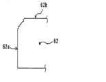
- the elastic blade of polyurethane increases the frictional force between the image carrier 123 and the cleaning blade 62, and the cleaning blade 62 is pulled in the moving direction of the image carrier 123, so that the tip of the cleaning blade 62 The ridgeline part 62c turns over. Furthermore, if the cleaning is continued with the leading edge portion 62c of the cleaning blade 62 turned up, as shown in FIG. 6B, the cleaning blade 62 is separated from the leading edge portion 62c of the blade leading surface 62a by a few [ ⁇ m]. Local wear will occur. If the cleaning is further continued in such a state, the local wear becomes large, and finally the leading edge portion 62c is lost as shown in FIG. 6C. If the leading edge portion 62c is missing, the toner cannot be properly cleaned, resulting in poor cleaning.
- Reference numeral 62b represents a vertical plane of the tip ridge line portion.
- Patent Document 1 discloses a method of making the tip ridge line portion difficult to be deformed over time by making it impregnated with an ultraviolet curable resin so that the surface and the inside of the blade have high hardness.
- an ultraviolet curable resin is impregnated from the surface of the urethane rubber which is the base material of the elastic blade, and after the impregnation, excessively remains on the blade surface.
- An example is a method in which the resin is cured by ultraviolet irradiation after removing the resin.
- the step of removing the resin remaining excessively on the blade surface is performed by wiping in the longitudinal direction of the blade using a solvent.
- the resin on the surface of the urethane rubber but also the resin impregnated inside is extracted.
- the wiping force varies in the longitudinal direction of the blade, resulting in a gradient / unevenness in the amount of resin remaining inside the blade, and when it is finally cured, a large hardness gradient / unevenness appears. It was confirmed. If there is a hardness gradient / hardness unevenness in the longitudinal direction of the blade, since no uniform pressure is applied to the image carrier in the longitudinal direction, the toner partially slips, resulting in poor cleaning. In addition, if the contact time with the solvent used for wiping is long, the amount of the impregnated resin that is extracted increases, and even if the resin is cured, the tip ridge portion is curled without becoming high hardness. Slipping through and poor cleaning.
- the cleaning blade produced through the impregnation and curing treatment has a convex portion on the surface of the cured layer unless the blade surface residue is uniformly removed after the impregnation treatment.
- the toner slips around the convex portion, resulting in poor cleaning.
- Patent Document 2 after impregnating with an isocyanate compound, a process of wiping with excess solvent to blow off excess isocyanate compound by applying hot air and further wiping with a solvent is used. A sufficient treatment cannot be performed only with the treatment with hot air, and the wiping and removal with a solvent causes a hardness difference in the longitudinal direction of the blade as described above.
- the present invention has been made in view of the above background, and an object thereof is caused by a difference in hardness in the longitudinal direction of the elastic blade or a convex portion on the surface of the elastic blade in a method for manufacturing a cleaning blade having at least a strip-shaped elastic blade. It is an object of the present invention to provide a method for manufacturing a cleaning blade capable of solving a cleaning failure.
- a method for manufacturing a cleaning blade according to the present invention includes: A method of manufacturing a cleaning blade having at least a strip-shaped elastic blade, (1) a step of producing an elastic blade preform made of polyurethane rubber; (2) impregnating an ultraviolet curable composition containing a (meth) acrylate compound into at least the image carrier contact portion of the elastic blade preform, (3) a step of immersing the impregnated portion of the elastic blade preform in a cleaning solvent to remove the ultraviolet curable composition containing the (meth) acrylate compound remaining on the surface of the impregnated portion; and (4) a step of curing the ultraviolet curable composition containing the (meth) acrylate compound impregnated in the elastic blade preform, to obtain an elastic blade; It is characterized by having.
- the ultraviolet curable composition containing the (meth) acrylate compound in the method for producing a cleaning blade according to the present invention, after the surface of the elastic blade preform is impregnated with the ultraviolet curable composition containing the (meth) acrylate compound, the excess remaining on the surface of the elastic blade preform.
- the ultraviolet curable composition By removing the ultraviolet curable composition by immersing it in a cleaning solvent for a certain period of time, the ultraviolet curable composition can be removed uniformly in the longitudinal direction of the blade, thereby suppressing toner slippage. A cleaning defect can be solved.
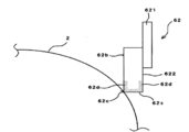
- FIG. 1A is an enlarged cross-sectional view of the cleaning blade, and is an explanatory view showing a state where the cleaning blade is in contact with the surface of the photoreceptor.
- FIG. 1B is an enlarged cross-sectional view of the cleaning blade, and is an enlarged explanatory view of the vicinity of the tip ridge line portion 62 c of the cleaning blade 62.
- FIG. 2 is a schematic configuration diagram of a printer according to an embodiment of the present invention.
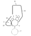
- FIG. 3 is a schematic configuration diagram of an image forming unit according to an embodiment of the present invention.
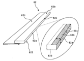
- FIG. 4 is a perspective view of a cleaning blade according to an embodiment of the present invention.
- FIG. 5 is a schematic diagram showing the measurement location of the wear width of the elastic blade.
- FIG. 6A is a diagram illustrating a state in which the edge portion of the cleaning blade is turned up.
- FIG. 6B is a diagram illustrating local wear on the tip surface of the cleaning blade.
- FIG. 6C is a diagram illustrating a state in which a tip ridge line portion of the cleaning blade is missing.
- the method for manufacturing a cleaning blade of the present invention is a method for manufacturing a cleaning blade having at least a strip-shaped elastic blade, and includes the following steps. (1) a step of producing an elastic blade preform made of polyurethane rubber; (2) impregnating an ultraviolet curable composition containing a (meth) acrylate compound into at least the image carrier contact portion of the elastic blade preform, (3) a step of immersing the impregnated portion of the elastic blade preform in a cleaning solvent to remove the ultraviolet curable composition containing the (meth) acrylate compound remaining on the surface of the impregnated portion; and (4) A step of curing the ultraviolet curable composition containing the (meth) acrylate compound impregnated in the elastic blade preform to obtain an elastic blade.
- the excess ultraviolet curable composition remaining on the surface of the elastic blade preform is washed.
- the ultraviolet curable composition can be removed uniformly in the longitudinal direction of the elastic blade preform.
- the SP value of the cleaning solvent is that of a general acrylic resin. It is desirable that the value is close to 9.5 and the compatibility with the ultraviolet curable composition is high. Specifically, the SP value is preferably 8.0 or more and 11.5 or less.
- the “solubility parameter value (SP) value” is a value defined by the regular solution theory introduced by Hildebrand, and is a measure of the solubility of the binary solution. Although there is a parameter value of itself, it is shown as a scale representing intermolecular force. Accordingly, those having a high SP value include polar compounds such as water, and those having a low SP value include hydrophobic compounds.
- the solvent capable of dissolving the ultraviolet curable composition also extracts the ultraviolet curable composition impregnated in the rubber, a cured layer on the surface may not be stably formed.
- the solvent used for cleaning is preferably a solvent having a high viscosity and hardly penetrates into the elastic blade preform, and preferably has a viscosity at 20 ° C. of 0.9 [mPa ⁇ s] or more. mPa ⁇ s] or less is more preferable.
- the viscosity can be measured by an ordinary method. For example, it can be measured by using a viscometer manufactured by Brooklyn and using a spindle.
- the vapor pressure at 20 ° C. is preferably 15 [kPa] or less, more preferably 0.1 [kPa] or more.
- the rate of penetration into the elastic blade preform is slower when the cleaning solvent contains a compound whose chemical structure has a cyclic structure.
- the ring structure is bulky as compared with the straight chain structure and the like, and the obstacle when entering the elastic blade preform is large. Therefore, as the cleaning solvent, a solvent having an annular structure, difficult to penetrate into the elastic blade preform, and difficult to extract the impregnated ultraviolet curable composition is preferable.
- Cyclohexane SP value 8.2, viscosity (20 ° C.) 0.98 mPa ⁇ s, vapor pressure (20 ° C.) 10.4 kPa
- Cyclohexanone SP value 9.9, viscosity (20 ° C.) 1.78 mPa ⁇ s, vapor pressure (20 ° C.) 0.5 kPa 1-methoxy-2-propanol: SP value 10.4, viscosity (20 ° C.) 1.81 mPa ⁇ s, vapor pressure (20 ° C.) 1 kPa 1-butanol: SP value 11.4, viscosity (20 ° C.) 3 mPa ⁇ s, vapor pressure (20 ° C.) 0.6 kPa Methyl ethyl ketone: SP value 9.3, viscosity (20 ° C.) 0.4 mPa ⁇ s, vapor pressure (20 ° C.) 10.5 kPa Tolu
- a step of removing the residual solvent on the elastic blade preform after immersion in a cleaning solvent may be added.
- the removal method include air drying, a method of absorbing by a nonwoven fabric or sponge, a method of sliding a member such as rubber, metal, or glass on the elastic blade preform, scraping removal, etc. is not.
- the cleaning blade of the present invention is a cleaning blade having at least a strip-shaped elastic blade, and the elastic blade has a (meth) acrylate compound at least on an image carrier contact portion of an elastic blade preform formed of polyurethane rubber.
- the variation in direction is 35% or less.
- the Martens hardness on the surface of the impregnated portion of the elastic blade there is no particular limitation on the Martens hardness on the surface of the impregnated portion of the elastic blade, but in order to prevent the toner from slipping through, the Martens hardness in the longitudinal direction measured from the surface at a position 20 ⁇ m away from the edge of the tip on the horizontal and vertical planes. Is required to be 35% or less, preferably 30% or less.
- the impregnated portion of the elastic blade is a portion obtained by impregnating the elastic blade preform with an ultraviolet curable composition containing a (meth) acrylate compound and curing it.
- the Martens hardness was measured from the surface at 10 locations.
- the value of the variation in Martens hardness in the longitudinal direction was obtained by calculating the average of 5 points for each of the horizontal plane and the vertical plane, and determining the maximum percentage of variation from the average value.
- the horizontal plane refers to the front end surface of the elastic blade including the front edge portion and facing the upstream surface in the traveling direction of the image carrier, and the vertical surface includes the front edge portion and facing the downstream surface in the traveling direction of the image carrier. Say the face.
- FIG. 4 is a perspective view of the cleaning blade 62
- FIG. 5 is an enlarged cross-sectional view of the cleaning blade 62.
- the cleaning blade 62 includes a strip-shaped holder 621 made of a rigid material such as metal or hard plastic, and a strip-shaped elastic blade 622.
- the elastic blade 622 is fixed to one end side of the holder 621 by an adhesive or the like, and the other end side of the holder 621 is cantilevered by the case of the cleaning means 3.
- the elastic blade 622 preferably has a high rebound resilience rate so that it can follow the eccentricity of the photosensitive member 2 and minute waviness on the surface of the photosensitive member.
- 62a indicates a front end surface (the horizontal surface)
- 62b indicates a vertical surface of the front end ridge line portion.
- the elastic blade preform formed of the polyurethane rubber is not particularly limited and may be appropriately selected depending on the intended purpose.
- a polyurethane prepolymer is prepared using a polyol compound and a polyisocyanate compound, and the polyurethane A prepolymer was added with a curing agent and, if necessary, a curing catalyst, cross-linked in a predetermined mold, and post-cross-linked in a furnace, formed into a sheet by centrifugal molding, allowed to stand at room temperature and aged It is manufactured by cutting a thing into a strip shape with a predetermined dimension.
- the polyol compound there is no restriction
- the high molecular weight polyol include a polyester polyol which is a condensate of an alkylene glycol and an aliphatic dibasic acid; ethylene adipate ester polyol, butylene adipate ester polyol, hexylene adipate ester polyol, ethylene propylene adipate ester polyol, ethylene butylene Polyester polyols such as polyester polyols of alkylene glycol and adipic acid such as adipate ester polyol and ethylene neopentylene adipate ester polyol; polycaprolactone polyols such as polycaprolactone ester polyol obtained by ring-opening polymerization of caprolactone;
- low molecular weight polyol examples include dihydric alcohols such as 1,4-butanediol, ethylene glycol, neopentyl glycol, hydroquinone-bis (2-hydroxyethyl) ether; 1,1,1-trimethylolpropane, glycerin 1,2,6-hexanetriol, 1,2,4-butanetriol, trimethylolethane, 1,1,1-tris (hydroxyethoxymethyl) propane, diglycerin, pentaerythritol and the like And polyhydric alcohols. These may be used individually by 1 type and may use 2 or more types together.
- dihydric alcohols such as 1,4-butanediol, ethylene glycol, neopentyl glycol, hydroquinone-bis (2-hydroxyethyl) ether
- 1,1,1-trimethylolpropane glycerin 1,2,6-hexanetriol
- 1,2,4-butanetriol trimethylolethane
- the polyisocyanate compound is not particularly limited and may be appropriately selected depending on the intended purpose.
- the curing catalyst is not particularly limited and may be appropriately selected depending on the intended purpose. Examples thereof include 2-methylimidazole and 1,2-dimethylimidazole.
- the amount of the curing catalyst used is not particularly limited and may be appropriately selected depending on the intended purpose, but is preferably 0.01% by mass to 0.5% by mass with respect to the polyurethane prepolymer, and 0.05% by mass. % To 0.3% by mass is more preferable.
- the elastic blade preform can be a two-layer type in which two different materials are laminated.
- FIG. 1A and 1B are enlarged sectional views of the cleaning blade 62.
- FIG. FIG. 1A is an explanatory view showing a state in which the cleaning blade 62 is in contact with the surface of the photosensitive member 2
- FIG. 1B is an enlarged explanatory view in the vicinity of the tip ridge line portion 62 c of the cleaning blade 62.
- the elastic blade 622 is obtained by impregnating at least the image carrier abutting portion of the elastic blade preform with an ultraviolet curable composition containing a (meth) acrylate compound. An impregnation process, which will be described in detail later, is performed on a certain tip ridge line portion 62c.
- reference numeral 62d denotes an impregnation range.
- the tan ⁇ peak temperature of the rubber measured with a DMS6100 manufactured by SII or the like is 0 [° C.] or higher, and each hardness at 23 [° C.] and 10 [° C.] ( The difference in JIS-A) is preferably 5 degrees or more.
- Step of impregnating at least the image carrier contact portion of the elastic blade preform with an ultraviolet curable composition containing a (meth) acrylate compound The image carrier contact portion of the elastic blade preform is preferably the tip ridge line portion of the elastic blade.
- the elastic blade preform is impregnated with an ultraviolet curable composition containing a (meth) acrylate compound so that the tip ridge portion is impregnated.
- the impregnation treatment to the tip ridge line portion 62c of the elastic blade 622 can be performed by impregnating the ultraviolet curable composition containing the (meth) acrylate compound by brush coating, spray coating, dip coating, or the like. .
- the impregnation treatment may be performed by impregnating the tip ridge line portion, but it is preferable to impregnate the tip ridge line portion to a position separated by 0.5 mm or more from each of the horizontal plane and the vertical plane.
- the lower end including the tip ridge line portion 62c of the elastic blade 622 is impregnated.
- the present invention is not limited to this, and the tip ridge line portion 62c to the tip surface 62a (horizontal plane) and the vertical surface 62b of the tip ridge line portion are each 0.5 mm. It is only necessary that the impregnation treatment is performed up to the above-described position.
- the range of 0.5 mm or more and 1 cm or less from the tip ridge is impregnated. If the impregnation range exceeds 1 cm, elasticity may be impaired.
- the impregnation time is preferably 5 minutes to 60 minutes, and the temperature during impregnation is preferably 10 ° C to 35 ° C.
- a (meth) acrylate compound having a molecular weight of 100 to 1,500 can be used.
- the (meth) acrylate compound having a molecular weight of 100 to 1,500 is not particularly limited and may be appropriately selected depending on the intended purpose. Examples thereof include dipentaerythritol hexa (meth) acrylate and pentaerythritol tetra (meth).
- compounds having a pentaerythritol triacrylate structure having 3 to 6 functional groups are preferable.
- Examples of the compound having a pentaerythritol triacrylate structure having 3 to 6 functional groups include pentaerythritol triacrylate, dipentaerythritol hexaacrylate, and the like.
- Examples of the acrylate or methacrylate having a tricyclodecane or adamantane skeleton include tricyclodecane dimethanol diacrylate, 1,3-adamantane dimethanol diacrylate, 1,3-adamantane dimethanol dimethacrylate, 1,3,5-adamantanetri There are methanol triacrylate, 1,3,5-adamantane trimethanol trimethacrylate, etc., and two or more of these may be used in combination.
- the number of functional groups of the acrylate or methacrylate having a tricyclodecane or adamantane skeleton is preferably 1 to 6, and more preferably 2 to 4. Since only one functional group has a weak cross-linking structure, and five or more functional groups may cause steric hindrance, it is preferable to mix acrylates or methacrylates having different numbers of functional groups.
- components are not particularly limited and may be appropriately selected depending on the intended purpose. Examples thereof include a photopolymerization initiator, a polymerization inhibitor, and a diluent.
- the photopolymerization initiator is not particularly limited as long as it generates active species such as radicals and cations by the energy of light and initiates polymerization, and can be appropriately selected according to the purpose.
- a polymerization initiator, a photocationic polymerization initiator, etc. are mentioned.
- a photo radical polymerization initiator is particularly preferable.
- radical photopolymerization initiator examples include aromatic ketones, acylphosphine oxide compounds, aromatic onium salt compounds, organic peroxides, thio compounds (thioxanthone compounds, thiophenyl group-containing compounds, etc.), hexaarylbiimidazoles, and the like.
- examples thereof include compounds, ketoxime ester compounds, borate compounds, azinium compounds, metallocene compounds, active ester compounds, compounds having a carbon halogen bond, and alkylamine compounds.
- the photo radical polymerization initiator is not particularly limited and may be appropriately selected depending on the intended purpose.
- radical photopolymerization initiator commercially available products can be used.
- commercially available products include Irgacure 651, Irgacure 184, DAROCUR1173, Irgacure 2959, Irgacure 127, Irgacure 907, Irgacure 369, Irgacure 379, DAROCUR TPO.
- Irgacure 819, Irgacure 784, Irgacure OXE 01, Irgacure OXE 02, Irgacure 754 (above, manufactured by Ciba Specialty Chemicals); Speedcure TPO (produced by Lambson); KAYACURE DETX-S; Lucirin TPO, LR8883, LR8970 (above, manufactured by BASF); Ubekrill P36 (manufactured by UCB), and the like. These may be used individually by 1 type and may use 2 or more types together.
- the content of the photopolymerization initiator is not particularly limited and may be appropriately selected depending on the intended purpose. It is preferably 1% by mass to 20% by mass with respect to the ultraviolet curable composition.
- the polymerization inhibitor is not particularly limited and may be appropriately selected depending on the intended purpose. Examples thereof include p-methoxyphenol, cresol, t-butylcatechol, di-t-butylparacresol, hydroquinone monomethyl ether, ⁇ - Naphthol, 3,5-di-tert-butyl-4-hydroxytoluene, 2,2'-methylenebis (4-methyl-6-tert-butylphenol), 2,2'-methylenebis (4-ethyl-6-butylphenol) Phenol compounds such as 4,4′-thiobis (3-methyl-6-t-butylphenol); p-benzoquinone, anthraquinone, naphthoquinone, phenanthraquinone, p-xyloquinone, p-toluquinone, 2,6-dichloroquinone 2,5-diphenyl-p-benzoquinone, 2,5-diacetoxy-p-benzo Non
- the ultraviolet curable resin is soluble and has a low boiling point.
- the boiling point is preferably 160 ° C. or lower, more preferably 100 ° C. or lower.
- Diluting solvents that can be used include hydrocarbon solvents such as toluene and xylene, ester solvents such as ethyl acetate, n-butyl acetate, methyl cellosolve acetate, propylene glycol monomethyl ether acetate, or methyl ethyl ketone, methyl isobutyl ketone, diisobutyl ketone, and cyclohexanone.
- Ketones such as cyclopentanone and acetone
- ethers such as ethylene glycol monomethyl ether, ethylene glycol monoethyl ether and propylene glycol monomethyl ether
- alcohols such as ethanol, propanol, 1-butanol, isopropyl alcohol and isobutyl alcohol
- organic solvents can also be used. These may be used individually by 1 type and may use 2 or more types together.
- Step of immersing the impregnated portion of the elastic blade preform in a cleaning solvent to remove the ultraviolet curable composition containing the (meth) acrylate compound remaining on the surface of the impregnated portion Step of immersing the impregnated portion of the elastic blade preform in a cleaning solvent to remove the ultraviolet curable composition containing the (meth) acrylate compound remaining on the surface of the impregnated portion
- the impregnated portion of the elastic blade preform in which the image bearing member contact portion is impregnated with an ultraviolet curable composition containing a (meth) acrylate compound is immersed in the cleaning solvent, and the surface of the impregnated portion is immersed.
- the UV curable composition remaining on the surface is removed. It is preferable to immerse at least the region of the cleaning solvent impregnated with the ultraviolet curable composition at a temperature not higher than the boiling point of the cleaning solvent.
- the immersion treatment is more preferably performed at a temperature of 10 ° C to 30 ° C.
- the treatment time cannot be generally specified because the cleaning ability varies depending on the solvent type, but it is preferably 1 second or more and 1 minute or less, more preferably 30 seconds or less, and particularly preferably 20 seconds or less.
- it is preferable to contact with the solvent for 1 second or longer, and in order to reduce the extraction amount of the impregnated resin, 1 minute or shorter is preferable. This is because if the immersion time is long, the resin impregnated in the vicinity of the surface of the impregnated portion is extracted even if the solvent penetrates slowly into the blade. When the extraction amount of the impregnated resin is increased, the tip ridge line portion is curled without increasing the hardness even if the resin is cured.
- Step of curing the ultraviolet curable composition containing the (meth) acrylate compound impregnated in the elastic blade preform to obtain an elastic blade There are no particular limitations on the irradiation conditions of the ultraviolet rays used to cure the ultraviolet curable cured product, and it can be appropriately selected according to the purpose. However, the integrated light quantity is 500 mJ / cm 2 to 5,000 mJ / cm. 2 is preferred.
- the image forming apparatus of the present invention includes an image carrier, a charging unit for charging the surface of the image carrier, a latent image forming unit for forming an electrostatic latent image on the charged surface of the image carrier, and the image carrier.
- a developing unit that develops the electrostatic latent image formed on the surface to form a toner image; a transfer unit that transfers the toner image on the surface of the image carrier to a transfer member;
- the cleaning blade of the present invention is used as the cleaning blade in an image forming apparatus including a cleaning unit having a cleaning blade for cleaning the transfer residual toner attached to the surface of the image carrier.
- FIG. 2 is an overall configuration diagram showing an outline of the image forming apparatus of the present invention. The main part of the image forming apparatus will be described below with reference to FIG.
- the image forming apparatus includes four process units 1K, 1C, 1M, and 1Y each having an image forming unit for forming an image with developers of different colors of black, cyan, magenta, and yellow corresponding to color separation components of a color image. It has.
- the process units 1K, 1C, 1M, and 1Y have the same configuration except that they store different color toners.
- the configuration of the process unit 1K will be described by taking the process unit 1K as an example.
- the process unit 1K includes an image carrier (photosensitive member) 2, a cleaning unit 3, a charging unit 4, a developing unit 5, a toner storage unit 6, and the like. ing.
- the process unit 1K is detachably attached to the main body of the image forming apparatus. As shown in FIG. 2, an exposure unit 7 is disposed above the process units 1K, 1C, 1M, and 1Y.
- the exposure unit 7 is configured to emit laser beams (L1 to L4) from the laser diode based on the image data.
- a transfer belt device 8 is disposed below each process unit 1K, 1C, 1M, 1Y.
- the transfer belt device 8 includes an intermediate transfer belt 12 for transferring a toner image formed by the image carrier 2.
- the intermediate transfer belt 12 is configured to be spanned between four primary transfer rollers 9 a, 9 b, 9 c, 9 d facing each image carrier 2, a driving roller 10, a tension roller 11, and a cleaning backup roller 15 and rotationally driven.
- a secondary transfer roller 13 is disposed facing the driving roller 10, and a belt cleaning device 14 is disposed facing the cleaning backup roller 15.
- a paper feed cassette 16 capable of storing a large number of sheets
- a paper feed roller 17 for feeding the sheets from the paper feed cassette 16.
- a registration roller pair 18 for temporarily stopping the paper is provided.
- a fixing device 19 having a fixing roller 25, a pressure roller 26, and the like is provided above the fixing device 19, a pair of paper discharge rollers 20 for discharging the paper to the outside is disposed above the fixing device 19, a pair of paper discharge rollers 20 for discharging the paper to the outside is disposed above the fixing device 19, a pair of paper discharge rollers 20 for discharging the paper to the outside is disposed.
- the paper discharged by the paper discharge roller pair 20 is configured to be stacked on a paper discharge tray 21 formed by recessing the upper surface of the image forming apparatus main body inward.
- waste toner container 22 for storing waste toner is disposed.
- a waste toner transfer hose (not shown) extending from the belt cleaning device 14 is connected to the entrance of the waste toner container 22.
- FIG. 3 is a schematic configuration diagram showing a state before the process unit 1K is removed from the main body of the image forming apparatus or before mounting.
- the process unit has a housing 23.
- the casing 23 is formed by resin injection molding.
- this resin for example, a polycarbonate resin, a tolyl butadiene styrene resin for acrylic, a tolyl styrene resin for acrylic, a styrene resin, a polyphenylene ether resin, a polyphenylene oxide resin, a polyether terephthalate resin, or an alloy resin thereof is applied.
- the image carrier 2, the cleaning unit 3, the charging unit 4, the developing unit 5 and the like are arranged.
- the cleaning means has the cleaning blade of the present invention.
- a print execution signal is received from an operation unit (not shown) or the like, a predetermined voltage or current is sequentially applied to the charging unit 4 and the developing roller 5 at predetermined timing. Similarly, a predetermined voltage or current is sequentially applied to the exposure apparatus and the charge removal lamp at predetermined timing.
- the photosensitive member 2 is rotationally driven in the direction of the arrow in the figure by a photosensitive member driving motor (not shown) as driving means.
- the surface of the photosensitive member is first charged to a predetermined potential by the charging means 4. Then, light L corresponding to the image signal is irradiated onto the photoconductor 2 from an exposure device (not shown), and the portion of the photoconductor 2 irradiated with the light L is neutralized to form an electrostatic latent image.
- the photosensitive member 2 on which the electrostatic latent image is formed is rubbed against the surface of the photosensitive member 2 with a developer magnetic brush formed on the developing roller at a portion facing the developing means 5.
- the negatively charged toner on the developing roller moves to the electrostatic latent image side by a predetermined developing bias applied to the developing roller and is converted into a toner image (development).
- the electrostatic latent image formed on the photoreceptor 2 is reversely developed by the developing unit 5 with the negatively charged toner.
- N / P negative positive: toner adheres to a place where the potential is low
- the toner image formed on the photosensitive member 2 is transferred between a photosensitive member 2 and a transfer device as a transfer unit from a paper feeding unit (not shown) through an opposing portion of the upper registration roller and the lower registration roller.
- the image is transferred onto a transfer sheet fed to the area.
- the transfer paper is supplied in synchronism with the leading edge of the image at the facing portion between the upper registration roller and the lower registration roller.
- a predetermined transfer bias is applied during transfer onto the transfer paper.
- the transfer paper onto which the toner image has been transferred is separated from the photoreceptor 2 and conveyed to a fixing device (not shown) as fixing means.
- the toner image is fixed on the transfer paper by the action of heat and pressure, and the transfer paper is discharged out of the apparatus.
- the surface of the photoreceptor 2 after the transfer is removed by the cleaning means 3 to remove the residual toner after the transfer, and the charge is removed by the charge eliminating lamp.
- the image carrier and a cleaning unit having at least a cleaning blade for removing transfer residual toner attached to the surface of the image carrier are integrally supported, and are detachable from the image forming apparatus main body.
- It can be a process cartridge.
- an image carrier (photosensitive member) 2 and cleaning means 3, charging means 4, developing means 5 and the like as process means are housed in a housing 23, and can be integrally attached to and detached from the apparatus main body as a process cartridge. It has become.
- the photosensitive member 2 as the process cartridge and the process means are integrally replaced.
- units such as the photosensitive member 2, the cleaning means 3, the charging means 4, and the developing means 5 are used. It is also possible to replace it with a new one.
- a method for manufacturing a cleaning blade having at least a strip-shaped elastic blade including the following steps: (1) a step of producing an elastic blade preform made of polyurethane rubber; (2) impregnating an ultraviolet curable composition containing a (meth) acrylate compound into at least the image carrier contact portion of the elastic blade preform, (3) a step of immersing the impregnated portion of the elastic blade preform in a cleaning solvent to remove the ultraviolet curable composition containing the (meth) acrylate compound remaining on the surface of the impregnated portion; and (4) A step of curing the ultraviolet curable composition containing the (meth) acrylate compound impregnated in the elastic blade preform to obtain an elastic blade.
- an image carrier Charging means for charging the surface of the image carrier; Latent image forming means for forming an electrostatic latent image on the surface of the charged image carrier; Developing means for developing the electrostatic latent image formed on the surface of the image bearing member into a toner image; Transfer means for transferring the toner image on the surface of the image carrier to a transfer member;
- an image forming apparatus provided with a cleaning unit having a cleaning blade that contacts the surface of the image carrier and cleans transfer residual toner attached to the surface of the image carrier.
- the image forming apparatus wherein the cleaning blade is the cleaning blade according to [7].
- part means “part by mass” unless otherwise specified.
- Examples 1 to 14 and Comparative Examples 1 to 4 [Elastic blade preform] Referring to a method for producing a single-layer cleaning blade described as a reference example in Japanese Patent Application Laid-Open No. 2011-141449, 48.56 parts by mass of p-MDI and PCL210N (polycaprolactone using a linear glycol as an initiator) Diol, number average molecular weight 1000; Daicel Chemical Industries) 51.44 parts by mass in advance, a prepolymer was prepared, 40.82 parts by mass of this prepolymer and PCL210N, 3.34 parts by mass of trimethylolpropane as a crosslinking agent, Further, 5.22 parts by mass of 1,4-butanediol as a chain extender was mixed to obtain a polyurethane stock solution.
- p-MDI and PCL210N polycaprolactone using a linear glycol as an initiator
- Diol number average molecular weight 1000
- Daicel Chemical Industries 51.44 parts by mass
- This polyurethane stock solution was made into a strip-shaped elastic blade preform with an average thickness of 1.8 mm, 11.5 mm ⁇ 32.6 cm by centrifugal molding.
- the obtained elastic blade preform had a JIS-A hardness of 68 degrees and a rebound resilience of 30%.
- the hardness of the elastic blade preform was measured according to JIS K6253 using a micro rubber hardness meter MD-1 manufactured by Kobunshi Keiki Co., Ltd.
- the rebound resilience of the elastic blade preform is No. manufactured by Toyo Seiki Seisakusho.
- the measurement was performed according to JIS K6255 using a 221 regilynester.
- the sample was a stack of about 2 [mm] sheets so that the thickness was 4 [mm] or more.
- UV curable resin tricyclodecane dimethanol diacrylate (manufactured by Shin-Nakamura Chemical Co., Ltd., trade name: A-DCP, functional group number 2, molecular weight 304) 80 parts Polymerization initiator: Ciba Specialty Chemicals Irgacure 184 5 parts Solvent: Cyclohexanone 15 parts
- UV curable resin 1,3-adamantane dimethanol diacrylate (manufactured by Idemitsu Kosan Co., Ltd., XA-201, functional group number 2, molecular weight 304) 50 parts
- Polymerization initiator Ciba Specialty Chemicals Irgacure 184 5 parts
- Solvent 45 parts of cyclohexanone
- UV curable resin pentaerythritol triacrylate (manufactured by Daicel Cytec, PETIA, functional group number 3, molecular weight 298) 50 parts
- Polymerization initiator Ciba Specialty Chemicals Irgacure 184 5 parts
- Solvent cyclohexanone 45 parts
- the leading edge ridge line portion that becomes the image carrier contact portion of the elastic blade preform was impregnated with a curable material (impregnated material) shown in Table 2.
- the impregnation range is the lower end including the tip ridge line portion of the elastic blade as indicated by reference numeral 62d in FIG. 1B, and the lower end was immersed in a hardening material (impregnation material) at a depth of 2 mm and impregnated.
- the impregnation time was 20 minutes and the temperature was 24 ° C.
- immersion in a solvent was carried out in Examples 1 to 14, wiped off with a solvent in Comparative Examples 1 to 3, and dry wiping without using a solvent in Comparative Example 4.
- Table 1 shows the characteristic values of each solvent. (The vapor pressure indicates the MSDS value of Kanto Chemical Co., Inc.)
- the crosslinked structure by each hardening material was formed by the above-mentioned dipping coating method.
- the dipping step is specifically performed by impregnating the elastic blade preform with the curing material (impregnation material) 1 to 3 at 24 ° C. for 20 minutes, and then using the cleaning solvent. Immersion washing was performed at 24 ° C. for 20 seconds (Examples 1 to 13) or for 1 minute (Example 14). After washing, the solvent remaining on the surface was wiped off with a sponge, and ultraviolet exposure (140 [W / cm] ⁇ 5 [m / min] ⁇ 5 passes) was performed. Furthermore, it dried for 15 minutes at the internal temperature of 100 degreeC using the heat dryer.
- curable materials (impregnated materials) 1 and 2 were used for impregnation at 24 ° C. for 20 minutes, and then a wiping solvent was soaked into Bencott (Asahi Kasei Co., Ltd.), and the residue in the impregnated portion of the blade Was wiped off in the longitudinal direction of the blade, and ultraviolet exposure (140 [W / cm] ⁇ 5 [m / min] ⁇ 5 passes) was performed. Furthermore, it dried for 15 minutes at the internal temperature of 100 degreeC using the heat dryer. In Comparative Example 4, the cured material 2 was used for impregnation at 24 ° C.
- the dispersion in the longitudinal direction of the Martens hardness measured from the surface of the impregnated portion of the obtained elastic blade at a position 20 [ ⁇ m] away from the tip ridge line portion on the horizontal plane and the vertical plane was measured as follows. Specifically, the five points of the edge (tip ridge line part) that contacts the image carrier of the elastic blade are equally divided into five parts at a position 20 ⁇ m away from the tip ridge line part of the elastic blade impregnated part in a plane perpendicular to the horizontal plane. Martens hardness was measured from the surface at each of 5 locations (10 locations in total).
- the value of the variation in Martens hardness in the longitudinal direction was obtained by calculating the average of 5 points for each of the horizontal plane and the vertical plane, and determining the maximum percentage of variation from the average value. The results are shown in Table 2.
- the hardness variation shown in Table 2 indicates the larger of the maximum variations in the horizontal plane and the vertical plane.
- Hardness measurement Using a fine hardness tester FISCHERSCOPE HM2000 manufactured by FISCHER, measurement was performed from the surface of each blade at an indentation load of 2 mN and an indentation time of 10 s at a location 20 ⁇ m from the tip ridgeline.
- the obtained elastic blade was fixed with an adhesive to a sheet metal holder that can be mounted on the Ricoh color composite machine imgio MP C5001 to obtain a prototype cleaning blade.
- This was also attached to a Ricoh color composite machine imagio MP C5001 (same configuration as in FIG. 2), and image forming apparatuses of Examples 1 to 14 and Comparative Examples 1 to 4 were produced.
- the cleaning blade was attached with a linear pressure and a cleaning angle set according to a predetermined tip biting amount and attachment angle. Also, the lubricant application device was removed.
- a toner prepared by a polymerization method was used.
- the physical properties of the toner are as follows.
- Toner base circularity 0.98, average particle size 4.9 [ ⁇ m]
- External additive 1.5 parts of small particle size silica (Clariant H2000) 0.5 parts of small particle size titanium oxide (Taika MT-150AI) 1.0 parts of large particle size silica (UFP-30H manufactured by Denki Kagaku Kogyo)
- the blending amount of the external additive is a blending amount with respect to 100 parts of the toner base.
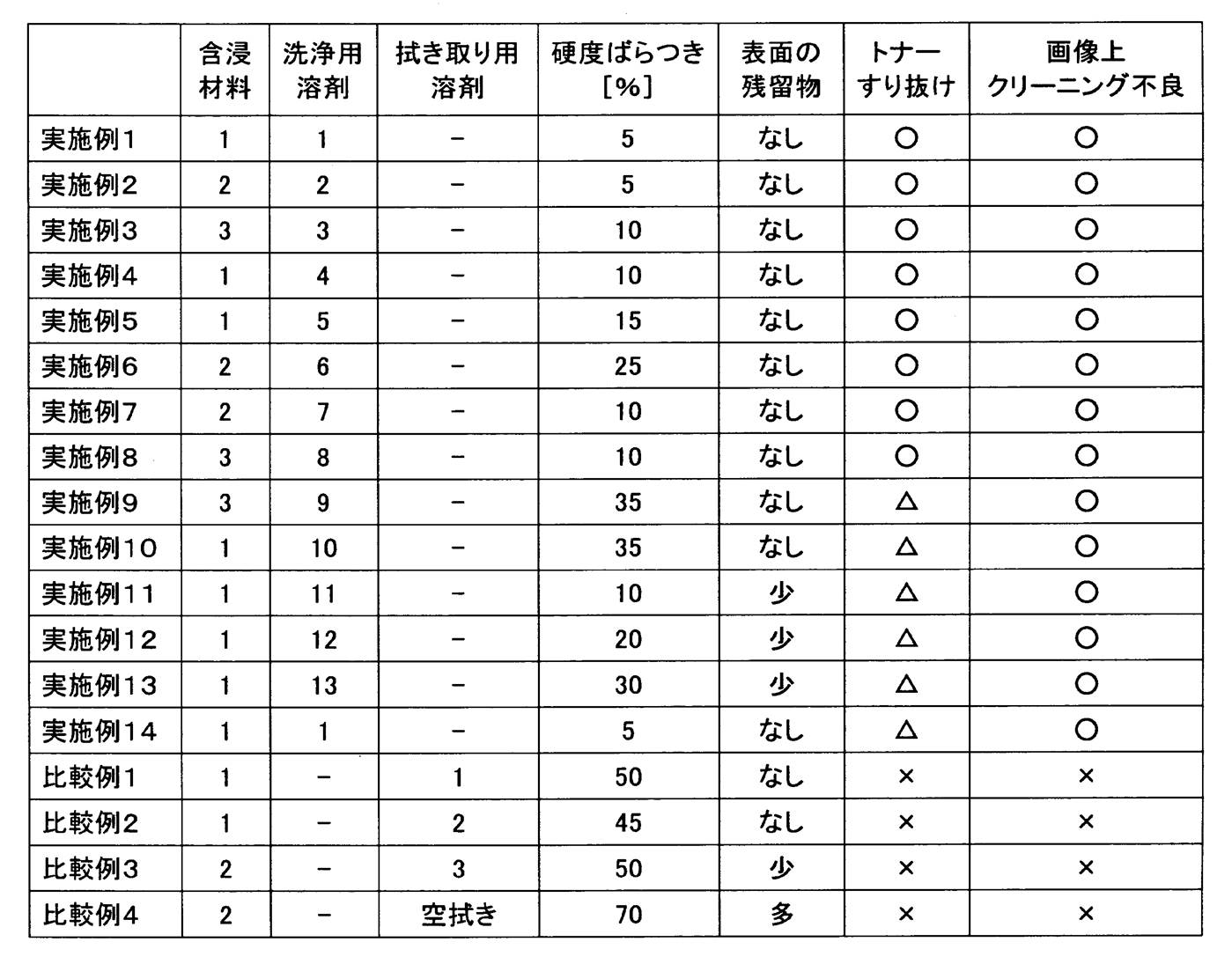
- Table 2 shows the evaluation results of Examples and Comparative Examples.
- the surface residue removing step after impregnating the ultraviolet curable composition into the image carrier contact portion of the elastic blade preform is immersed in a cleaning solvent instead of wiping with a solvent. It was confirmed that the hardness variation in the longitudinal direction of the blade was greatly reduced. It was also confirmed that when the SP value of the cleaning solvent was 8.0 or more and 11.5 or less, the compatibility with the (meth) acrylate compound was good and the surface could be cleaned without residue. Furthermore, by using a solvent having a viscosity at 20 ° C.
Landscapes
- Physics & Mathematics (AREA)
- General Physics & Mathematics (AREA)
- Cleaning In Electrography (AREA)
Abstract
Description
このクリーニング装置のクリーニング部材として、一般的に構成を簡単にでき、クリーニング性能も優れていることから、短冊形状の弾性ブレードを用いたものがよく知られている。この弾性ブレードは、ポリウレタンゴムなどの弾性体で構成されている。そして、弾性ブレードの基端を支持部材で支持して先端稜線部を像担持体の周面に押し当て、像担持体上に残留するトナーをせき止めて掻き落とし除去する。
少なくとも短冊形状の弾性ブレードを有するクリーニングブレードの製造方法であって、
(1)ポリウレタンゴムからなる弾性ブレード予備形成体を製造する工程、
(2)前記弾性ブレード予備形成体の少なくとも像担持体当接部に(メタ)アクリレート化合物を含む紫外線硬化性組成物を含浸させる工程、
(3)前記弾性ブレード予備形成体の含浸部分を洗浄用溶剤に浸漬し、前記含浸部分の表面に残留している前記(メタ)アクリレート化合物を含む紫外線硬化性組成物を取り除く工程、および、
(4)前記弾性ブレード予備形成体に含浸した前記(メタ)アクリレート化合物を含む紫外線硬化性組成物を硬化させ、弾性ブレードとする工程、
を有することを特徴とするものである。
(1)ポリウレタンゴムからなる弾性ブレード予備形成体を製造する工程、
(2)前記弾性ブレード予備形成体の少なくとも像担持体当接部に(メタ)アクリレート化合物を含む紫外線硬化性組成物を含浸させる工程、
(3)前記弾性ブレード予備形成体の含浸部分を洗浄用溶剤に浸漬し、前記含浸部分の表面に残留している前記(メタ)アクリレート化合物を含む紫外線硬化性組成物を取り除く工程、および、
(4)前記弾性ブレード予備形成体に含浸した前記(メタ)アクリレート化合物を含む紫外線硬化性組成物を硬化させ、弾性ブレードとする工程。
なお、本発明において、「溶解度パラメータ値(SP)値」とは、ヒルデブラント(Hildebrand)によって導入された正則溶液論により定義された値であり、2成分系溶液の溶解度の目安となるものであるが、そのもののパラメータ値は分子間力を表す尺度として示される。従って、SP値の高いものは水などの極性化合物が挙げられ、SP値が低いものは疎水性化合物が挙げられる。
なお、粘度は通常の方法で測定することができ、たとえばブルックリン社製粘度計を用い、スピンドルを使用することで測定することが可能である。
シクロヘキサン:SP値8.2、粘度(20℃)0.98mPa・s、蒸気圧(20℃)10.4kPa
シクロヘキサノン:SP値9.9、粘度(20℃)1.78mPa・s、蒸気圧(20℃)0.5kPa
1-メトキシ-2-プロパノール:SP値10.4、粘度(20℃)1.81mPa・s、蒸気圧(20℃)1kPa
1-ブタノール:SP値11.4、粘度(20℃)3mPa・s、蒸気圧(20℃)0.6kPa
メチルエチルケトン:SP値9.3、粘度(20℃)0.4mPa・s、蒸気圧(20℃)10.5kPa
トルエン:SP値8.9、粘度(20℃)0.59mPa・s、蒸気圧(20℃)3kPa
キシレン:SP値8.8、粘度(20℃)0.81mPa・s、蒸気圧(20℃)0.8kPa
酢酸ブチル:SP値8.5、粘度(20℃)0.74mPa・s、蒸気圧(20℃)1.3kPa
テトラヒドロフラン:SP値9.1、粘度(20℃)0.49mPa・s、蒸気圧(20℃)20kPa
アセトン:SP値9.9、粘度(20℃)0.32mPa・s、蒸気圧(20℃)22kPa
エタノール:SP値12.7、粘度(20℃)1.2mPa・s、蒸気圧(20℃)5.9kPa
ジエチルエーテル:SP値7.4、粘度(20℃)0.24mPa・s、蒸気圧(20℃)58.6kPa
エチレングリコール:SP値14.2、粘度(20℃)23.5mPa・s、蒸気圧(20℃)0.07kPa
等を好ましく用いることができる。特にシクロヘキサン、シクロヘキサノンが好ましい。
用いる洗浄用溶剤は1種のみでも良いし、2種以上を混合して使用しても良い。
前記弾性ブレードの含浸部分とは、弾性ブレード予備形成体に(メタ)アクリレート化合物を含む紫外線硬化性組成物を含浸させ、硬化させた部分である。
弾性ブレードの像担持体に当接する辺(先端稜線部)を5等分した点の5箇所について、弾性ブレード含浸部分の先端稜線部から水平面と垂直面で20μm離れた位置のそれぞれ5箇所(合計10箇所)について表面からマルテンス硬度を測定した。また、長手方向におけるマルテンス硬度のばらつきの値は、水平面と垂直面それぞれ5点の平均を求め、その平均値から最大で何%ばらついているか求めた。
前記水平面は、先端稜線部を含み像担持体の進行方向上流側の面と対向する弾性ブレード先端面を言い、垂直面は先端稜線部を含み像担持体の進行方向下流側の面と対向する面を言う。
クリーニングブレード62は、金属や硬質プラスチックなどの剛性材料からなる短冊形状のホルダー621と、短冊形状の弾性ブレード622とで構成されている。
弾性ブレード622としては、感光体2の偏心や感光体表面の微小なうねりなどに追随できるように、高い反発弾性体率を有するものが好ましい。
図4において、62aは先端面(前記水平面)を、62bは先端稜線部の垂直面を示す。
前記ポリウレタンゴムからなる弾性ブレード予備形成体は、特に制限はなく、目的に応じて適宜選択することができるが、例えば、ポリオール化合物とポリイソシアネート化合物とを用いてポリウレタンプレポリマーを調製し、該ポリウレタンプレポリマーに硬化剤、及び必要に応じて硬化触媒を加えて、所定の型内にて架橋し、炉内にて後架橋させたものを遠心成型によりシート状に成型後、常温放置、熟成したものを所定の寸法にて、短冊形状に裁断することにより、製造される。
前記高分子量ポリオールとしては、例えば、アルキレングリコールと脂肪族二塩基酸との縮合体であるポリエステルポリオール;エチレンアジペートエステルポリオール、ブチレンアジペートエステルポリオール、ヘキシレンアジペートエステルポリオール、エチレンプロピレンアジペートエステルポリオール、エチレンブチレンアジペートエステルポリオール、エチレンネオペンチレンアジペートエステルポリオール等のアルキレングリコールとアジピン酸とのポリエステルポリオール等のポリエステル系ポリオール;カプロラクトンを開環重合して得られるポリカプロラクトンエステルポリオール等のポリカプロラクトン系ポリオール;ポリ(オキシテトラメチレン)グリコール、ポリ(オキシプロピレン)グリコール等のポリエーテル系ポリオール、などが挙げられる。これらは、1種単独で使用してもよいし、2種以上を併用してもよい。
前記硬化触媒の使用量は、特に制限はなく、目的に応じて適宜選択することができるが、前記ポリウレタンプレポリマーに対して0.01質量%~0.5質量%が好ましく、0.05質量%~0.3質量%がより好ましい。
弾性ブレード622は、前記弾性ブレード予備形成体の少なくとも像担持体当接部に(メタ)アクリレート化合物を含む紫外線硬化性組成物を含浸処理がなされたものであり、前記像担持体当接部である先端稜線部62cに詳細は後述する含浸処理がなされている。
ここで、符号62dは、含浸範囲である。
弾性ブレード予備形成体の像担持体当接部としては、弾性ブレードの先端稜線部であることが好ましい。前記工程では、例えば、先端稜線部が含浸処理されるように弾性ブレード予備形成体を(メタ)アクリレート化合物を含む紫外線硬化性組成物に含浸させる。
弾性ブレード622の先端稜線部62cへの含浸処理は、ハケ塗り、スプレー塗工、ディップ塗工などによって、(メタ)アクリレート化合物を含む紫外線硬化性組成物を含浸させることで行うことが可能である。
含浸処理は、先端稜線部が含浸されれば良いが、先端稜線部から水平面及び垂直面それぞれ0.5mm以上離れた位置まで含浸させることが好ましい。図1Bにおいては弾性ブレード622の先端稜線部62cを含む下端が含浸されているが、これに限らず、先端稜線部62cから先端面62a(水平面)及び先端稜線部の垂直面62bそれぞれ0.5mm以上離れた位置まで含浸処理されていれば良い。先端稜線部から0.5mm以上1cm以下の範囲が含浸処理されていることがより好ましい。含浸処理される範囲が1cmを超えると弾性が損なわれることがある。
含浸時間は5分~60分、含浸時の温度は10℃~35℃が好ましい。
前記分子量が100~1,500の(メタ)アクリレート化合物としては、特に制限はなく、目的に応じて適宜選択することができ、例えば、ジペンタエリスリトールヘキサ(メタ)アクリレート、ペンタエリスリトールテトラ(メタ)アクリレート、ペンタエリスリトールトリ(メタ)アクリレート、ペンタエリスリトールエトキシテトラ(メタ)アクリレート、トリメチロールプロパントリ(メタ)アクリレート、トリメチロールプロパンエトキシトリ(メタ)アクリレート、1,6-ヘキサンジオールジ(メタ)アクリレート、エトキシ化ビスフェノールAジ(メタ)アクリレート、プロポキシ化エトキシ化ビスフェノールAジ(メタ)アクレリート、1,4-ブタンジオールジ(メタ)アクリレート、1,5-ペンタンジオールジ(メタ)アクリレート、1,6-ヘキサンジオールジ(メタ)アクリレート、1,7-ヘプタンジオールジ(メタ)アクリレート、1,8-オクタンジオールジ(メタ)アクリレート、1,9-ノナンジオールジ(メタ)アクリレート、1,10-デカンジオールジ(メタ)アクリレート、1,11-ウンデカンジオールジ(メタ)アクリレート、1,18-オクタデカンジオールジ(メタ)アクリレート、グリセリンプロポキシトリ(メタ)アクリレート、ジプロピレングリコールジ(メタ)アクリレート、トリプロピレングリコールジ(メタ)アクリレート、PO変性ネオペンチルグリコールジ(メタ)アクリレート、PEG600ジ(メタ)アクリレート、PEG400ジ(メタ)アクリレート、PEG200ジ(メタ)アクリレート、ネオペンチルグリコール・ヒドロキシピバリン酸エステルジ(メタ)アクリレート、オクチル/デシル(メタ)アクリレート、イソボルニル(メタ)アクリレート、エトキシ化フェニル(メタ)アクリレート、9,9-ビス[4-(2-(メタ)アクリロイルオキシエトキシ)フェニル]フルオレン、などが挙げられる。これらは、1種単独で使用してもよいし、2種以上を併用してもよい。これらの中でも、官能基数が3~6のペンタエリスリトールトリアクリレート構造を有する化合物が好ましい。
前記官能基数が3~6のペンタエリスリトールトリアクリレート構造を有する化合物としては、例えば、ペンタエリスリトールトリアクリレート、ジペンタエリスリトールヘキサアクリレート、などが挙げられる。
次に、前記像担持体当接部に(メタ)アクリレート化合物を含む紫外線硬化性組成物を含浸させた弾性ブレード予備形成体の含浸部分を、前記洗浄用溶剤に浸漬し、前記含浸部分の表面に残留している紫外線硬化性組成物を取り除く。
洗浄用溶剤に、少なくとも前記紫外線硬化性組成物を含浸した領域を、洗浄用溶剤の沸点以下の温度で浸漬することが好ましい。浸漬処理は、10℃~30℃の温度で行うことがより好ましい。また、処理時間は溶剤種により洗浄能力が異なるため一概には言えないが、1秒以上1分以下が好ましく、30秒以内がより好ましく、20秒以内が特に好ましい。表面に残った残渣を除去するためには、1秒以上溶剤と接触させることが好ましく、また、含浸した樹脂の抽出量を少なくするためには1分以下が好ましい。浸漬時間が長いとブレードへの染み入りが遅い溶剤であっても、含浸部表面近傍に含浸した樹脂が抽出されるからである。含浸した樹脂の抽出量が多くなると、樹脂を硬化させても高硬度とならずに先端稜線部が捲れてしまう。
前記紫外線硬化性硬化物を硬化するために使用する紫外線の照射条件については、特に制限はなく、目的に応じて適宜選択することができるが、積算光量が500mJ/cm2~5,000mJ/cm2が好ましい。
本発明の画像形成装置は、像担持体と、該像担持体表面を帯電する帯電手段と、帯電した該像担持体表面に静電潜像を形成する潜像形成手段と、該像担持体表面に形成された該静電潜像を現像してトナー像化する現像手段と、該像担持体表面の前記トナー像を転写体に転写する転写手段と、該像担持体表面に当接して、該像担持体表面に付着した転写残トナーをクリーニングするクリーニングブレードを有するクリーニング手段とを備えた画像形成装置において、上記クリーニングブレードとして、本発明のクリーニングブレードを用いる。
図2は、本発明の画像形成装置の概略を示す全体構成図である。以下、同図に基づいてこの画像形成装置の主要部を説明する。
図示しない操作部などからプリント実行の信号を受信したら、帯電手段4、現像ローラ5にそれぞれ所定の電圧または電流が順次所定のタイミングで印加される。同様に、露光装置及び除電ランプなどにもそれぞれ所定の電圧又は電流が順次所定のタイミングで印加される。また、これと同期して、駆動手段としての感光体駆動モータ(不図示)により感光体2が図中矢印方向に回転駆動される。
一方、転写後の感光体2の表面は、クリーニング手段3で転写後の残留トナーが除去され、除電ランプで除電される。
[1]少なくとも短冊形状の弾性ブレードを有するクリーニングブレードの製造方法であって、下記工程を有することを特徴とするクリーニングブレードの製造方法:
(1)ポリウレタンゴムからなる弾性ブレード予備形成体を製造する工程、
(2)前記弾性ブレード予備形成体の少なくとも像担持体当接部に(メタ)アクリレート化合物を含む紫外線硬化性組成物を含浸させる工程、
(3)前記弾性ブレード予備形成体の含浸部分を洗浄用溶剤に浸漬し、前記含浸部分の表面に残留している前記(メタ)アクリレート化合物を含む紫外線硬化性組成物を取り除く工程、および、
(4)前記弾性ブレード予備形成体に含浸した前記(メタ)アクリレート化合物を含む紫外線硬化性組成物を硬化させ、弾性ブレードとする工程。
[2]前記工程(3)に用いる前記洗浄用溶剤のSP値が、8.0以上、11.5以下である前記[1]に記載のクリーニングブレードの製造方法。
[3]前記工程(3)に用いる前記洗浄用溶剤の20℃における粘度が、0.9[mPa・s]以上である前記[1]又は[2]に記載のクリーニングブレードの製造方法。
[4]前記工程(3)に用いる前記洗浄用溶剤の20℃における蒸気圧が、15[kPa]以下である前記[1]~[3]のいずれかに記載のクリーニングブレードの製造方法。
[5]前記工程(3)に用いる前記洗浄用溶剤が、環状構造を有する化合物を含有する前記[1]~[4]のいずれかに記載のクリーニングブレードの製造方法。
[6]前記工程(3)において、前記弾性ブレード予備形成体の含浸部分を前記洗浄用溶剤に浸漬する浸漬時間が20秒以内である前記[1]~[5]のいずれかに記載のクリーニングブレードの製造方法。
[7]少なくとも短冊形状の弾性ブレードを有するクリーニングブレードであって、前記弾性ブレードはポリウレタンゴムからなる弾性ブレード予備形成体の少なくとも像担持体当接部に、(メタ)アクリレート化合物を含む紫外線硬化性組成物が含浸され、紫外線硬化された含浸部分を有し、前記含浸部分の水平面と垂直面で先端稜線部から20[μm]離れた位置での表面から測定したマルテンス硬度の長手方向におけるばらつきが、35[%]以下であることを特徴とするクリーニングブレード。
[8]像担持体と、
該像担持体表面を帯電する帯電手段と、
帯電した該像担持体表面に静電潜像を形成する潜像形成手段と、
該像担持体表面に形成された該静電潜像を現像してトナー像化する現像手段と、
該像担持体表面の前記トナー像を転写体に転写する転写手段と、
該像担持体表面に当接して、該像担持体表面に付着した転写残トナーをクリーニングするクリーニングブレードを有するクリーニング手段と
を備えた画像形成装置において、
前記クリーニングブレードが、前記[7]に記載のクリーニングブレードであることを特徴とする画像形成装置。
[9]像担持体と、少なくとも該像担持体表面に付着した転写残トナーを除去するクリーニングブレードを有するクリーニング手段とを一体に支持し、画像形成装置本体に対して着脱自在なプロセスカートリッジにおいて、
前記クリーニングブレードが、前記[7]に記載のクリーニングブレードであることを特徴とするプロセスカートリッジ。
なお、以下において、「部」は、特に明示しない限り「質量部」を表す。
[弾性ブレード予備形成体]
特開2011-141449号公報の参考例として記載の、単層のクリーニングブレードの作製方法を参照して、p-MDI 48.56質量部と、PCL210N(直鎖状グリコールを開始剤とするポリカプロラクトンジオール、数平均分子量1000;ダイセル化学工業)51.44質量部とで予めプレポリマーを製造し、このプレポリマーとPCL210N 40.82質量部と、架橋剤であるトリメチロールプロパン3.34質量部、および鎖延長剤である1,4-ブタンジオール5.22質量部とを混合してポリウレタン原液とした。このポリウレタン原液を、遠心成形法により平均厚み1.8mm、11.5mm×32.6cmの短冊形状の弾性ブレード予備形成体とした。
得られた弾性ブレード予備形成体のJIS-A硬度は68度、反発弾性率は30%であった。
弾性ブレード予備形成体の反発弾性は、東洋精機製作所製No.221レジリエンステスタを用い、JIS K6255に準じて測定した。試料は厚さ4[mm]以上となるように約2[mm]のシートを重ね合わせたものとした。
含浸処理に用いる紫外線硬化性組成物としては、以下の硬化材料1~3のものを用いた。
<硬化材料(含浸材料)1>
紫外線硬化樹脂:トリシクロデカンジメタノールジアクリレート
(新中村化学工業株式会社製、商品名:A-DCP、官能基数2、分子量304)
80部
重合開始剤 :チバスペシャリティーケミカルズ社 イルガキュア184 5部
溶媒 :シクロヘキサノン 15部
紫外線硬化樹脂:1,3-アダマンタンジメタノールジアクリレート
(出光興産株式会社製、X-A-201、官能基数2、分子量304) 50部
重合開始剤 :チバスペシャリティーケミカルズ社 イルガキュア184 5部
溶媒 :シクロヘキサノン 45部
紫外線硬化樹脂:ペンタエリスリトールトリアクリレート
(ダイセルサイテック社製、PETIA、官能基数3、分子量298) 50部
重合開始剤 :チバスペシャリティーケミカルズ社 イルガキュア184 5部
溶媒 :シクロヘキサノン 45部
含浸処理後の残留物除去工程としては、実施例1~14では溶剤への浸漬、比較例1~3では溶剤による拭き取り、比較例4では溶剤を使用しない乾拭きを実施した。
実施例1~14の洗浄用溶剤としては、以下の溶剤1~13のものを用い、上記含浸したブレードを24℃で浸漬させた。浸漬時間は、実施例1~13では20秒、実施例14では1分とした。
<溶剤1>
シクロヘキサン(関東化学製)
構造を以下に示す。

シクロヘキサノン(関東化学製)
構造を以下に示す。

1-メトキシ-2-プロパノール(関東化学製)
構造を以下に示す。

1-ブタノール(関東化学製)
構造を以下に示す。

メチルエチルケトン(関東化学製)
構造を以下に示す。

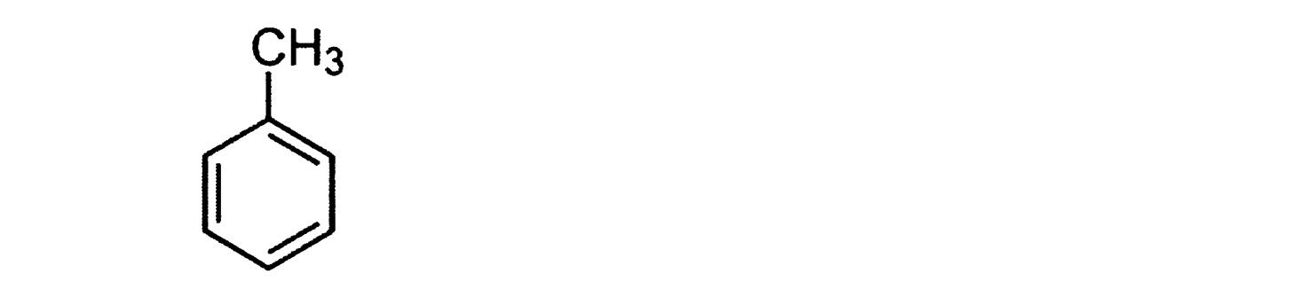
トルエン(関東化学製)
構造を以下に示す。
キシレン(関東化学製)
構造を以下に示す。(キシレンはオルト、メタ、パラ体の混合物を使用;以下はオルト体を示す。)

酢酸ブチル(関東化学製)
構造を以下に示す。

テトラヒドロフラン(関東化学製)
構造を以下に示す。

アセトン(関東化学製)
構造を以下に示す。

エタノール(関東化学製)
構造を以下に示す。

ジエチルエーテル
構造を以下に示す。

エチレングリコール
構造を以下に示す。

比較例1~3の拭き取り用溶剤としては、以下の溶剤1~3のものを用い、ベンコット(旭化成社製)に染み込ませ、ブレードの含浸部分の残留物を拭き取った。
<溶剤1>
メチルエチルケトン(関東化学製)
構造は上記の通りである。
<溶剤2>
トルエン(関東化学製)
構造は上記の通りである。
<溶剤3>
エタノール(関東化学製)
構造は上記の通りである。

比較例1~3では、硬化材料(含浸材料)1~2を用いて、24℃で20分間含浸したのち、拭き取り用溶剤をベンコット(旭化成社製)に染み込ませ、ブレードの含浸部分の残留物をブレードの長手方向に拭き取り、紫外線露光(140[W/cm]×5[m/min]×5パス)を行った。さらに、熱乾燥機を用いて庫内温度100℃で15分間乾燥を行った。
比較例4では、硬化材料2を用いて、24℃で20分間含浸したのち、ベンコット(旭化成社製)でブレードの含浸部分の残留物をブレードの長手方向に乾拭きし、紫外線露光(140[W/cm]×5[m/min]×5パス)を行った。さらに、熱乾燥機を用いて庫内温度100℃で15分間乾燥を行った。
具体的には、弾性ブレードの像担持体に当接する辺(先端稜線部)を5等分した点の5箇所について、弾性ブレード含浸部分の先端稜線部から水平面と垂直面で20μm離れた位置のそれぞれ5箇所(合計10箇所)について表面からマルテンス硬度を測定した。また、長手方向におけるマルテンス硬度のばらつきの値は、水平面と垂直面それぞれ5点の平均を求め、その平均値から最大で何%ばらついているか求めた。
結果を表2に示す。表2に記載した硬度ばらつきは、水平面と垂直面それぞれの最大のばらつきの大きい方を示している。硬度測定: FISCHER製微小硬さ試験機FISCHERSCOPE HM2000を用い、先端稜線部より20μmの箇所において、ブレード各々の表面から、押し込み荷重:2mN、押し込み時間:10sで測定。
キーエンス製マイクロスコープVHX-100を用いて観察し、ブレード表面の塗工液の残渣と思われる残留物の有無を確認し、以下のように判断した。
なし:先端稜線部に残留物が全くなくフラットな状態
少 :先端稜線部の一部に残留物が残っている状態
多 :先端稜線部の全域に残留物が残っている状態
得られた弾性ブレードをリコー製カラー複合機 imagio MP C5001に搭載できる板金ホルダーに接着剤により固定し、試作のクリーニングブレードとした。これを同じくリコー製カラー複合機 imagio MP C5001(図2と同様の構成)に取り付け、実施例1~14、比較例1~4の画像形成装置を作製した。なお、クリーニングブレードは、所定の先端食い込み量と取り付け角度により線圧とクリーニング角を設定して取り付けた。また、潤滑剤塗布装置は取り除いた。
トナー母体:円形度0.98、平均粒径4.9[μm]
外添剤 :小粒径シリカ1.5部(クラリアント製H2000)
小粒径酸化チタン0.5部(テイカ製MT-150AI)
大粒径シリカ1.0部(電気化学工業製UFP-30H)
外添剤の配合量は、トナー母体100部に対する配合量である。
[評価項目]
評価時画像:縦帯パターン(紙進行方向に対して)43[mm]幅、3本チャート
出力20枚(A4横)
トナーすり抜け評価:
クリーニングブレード直後の感光体表面上をテープで転写を行い、トナー等の有無を確認し、以下のように判断した。評価は、初期(10枚出力後)に上記画像を20枚出力したときと、10,000出力後に上記画像を20枚出力したときに行った。
○ :評価初期、10,000枚出力後共にすり抜けなし
△ :評価初期はすり抜けがないが、10,000枚出力後にすり抜けあり
× :評価初期ですり抜けあり
10,000枚の出力を行った後、縦帯パターン(紙進行方向に対して)43mm幅、3本チャートの評価時画像(A4サイズ横)を20枚出力した後の出力画像を目視観察し、以下の基準でクリーニング性を評価した。なお、異常画像とは、印刷画像にスジ又は帯状に現れる画像や白ポチ画像を意味する。
○ :異常画像なし
× :異常画像あり
1C プロセスユニット(シアン)
1M プロセスユニット(マゼンタ)
1Y プロセスユニット(イエロー)
2 像担持体(感光体)
3 クリーニング手段
4 帯電手段
5 現像手段(現像ローラ)
6 トナー貯蔵部
7 露光器
8 転写ベルト装置
9 一次転写ローラ
10 駆動ローラ
11 テンションローラ
12 中間転写ベルト
13 二次転写ローラ
14 ベルトクリーニング装置
15 クリーニングバックアップローラ
16 給紙カセット
17 給紙ローラ
18 レジストローラ対
19 定着装置
20 排紙ローラ対
21 排紙トレイ
22 廃トナー収容器
23 筐体
25 定着ローラ
26 加圧ローラ
62 クリーニングブレード
62a 先端面(水平面)
62b 先端稜線部の垂直面
62c 先端稜線部
62d 含浸範囲
123 像担持体
621 ホルダー
622 弾性ブレード
Claims (9)
- 少なくとも短冊形状の弾性ブレードを有するクリーニングブレードの製造方法であって、下記工程を有することを特徴とするクリーニングブレードの製造方法:
(1)ポリウレタンゴムからなる弾性ブレード予備形成体を製造する工程、
(2)前記弾性ブレード予備形成体の少なくとも像担持体当接部に(メタ)アクリレート化合物を含む紫外線硬化性組成物を含浸させる工程、
(3)前記弾性ブレード予備形成体の含浸部分を洗浄用溶剤に浸漬し、前記含浸部分の表面に残留している前記(メタ)アクリレート化合物を含む紫外線硬化性組成物を取り除く工程、および、
(4)前記弾性ブレード予備形成体に含浸した前記(メタ)アクリレート化合物を含む紫外線硬化性組成物を硬化させ、弾性ブレードとする工程。 - 前記工程(3)に用いる前記洗浄用溶剤のSP値が、8.0以上、11.5以下である請求項1に記載のクリーニングブレードの製造方法。
- 前記工程(3)に用いる前記洗浄用溶剤の20℃における粘度が、0.9[mPa・s]以上である請求項1又は2に記載のクリーニングブレードの製造方法。
- 前記工程(3)に用いる前記洗浄用溶剤の20℃における蒸気圧が、15[kPa]以下である請求項1~3のいずれかに記載のクリーニングブレードの製造方法。
- 前記工程(3)に用いる前記洗浄用溶剤が、環状構造を有する化合物を含有する請求項1~4のいずれかに記載のクリーニングブレードの製造方法。
- 前記工程(3)において、前記弾性ブレード予備形成体の含浸部分を前記洗浄用溶剤に浸漬する浸漬時間が20秒以内である請求項1~5のいずれかに記載のクリーニングブレードの製造方法。
- 少なくとも短冊形状の弾性ブレードを有するクリーニングブレードであって、前記弾性ブレードはポリウレタンゴムからなる弾性ブレード予備形成体の少なくとも像担持体当接部に、(メタ)アクリレート化合物を含む紫外線硬化性組成物が含浸され、紫外線硬化された含浸部分を有し、前記含浸部分の水平面と垂直面で先端稜線部から20[μm]離れた位置での表面から測定したマルテンス硬度の長手方向におけるばらつきが、35[%]以下であることを特徴とするクリーニングブレード。
- 像担持体と、
該像担持体表面を帯電する帯電手段と、
帯電した該像担持体表面に静電潜像を形成する潜像形成手段と、
該像担持体表面に形成された該静電潜像を現像してトナー像化する現像手段と、
該像担持体表面の前記トナー像を転写体に転写する転写手段と、
該像担持体表面に当接して、該像担持体表面に付着した転写残トナーをクリーニングするクリーニングブレードを有するクリーニング手段と
を備えた画像形成装置において、
前記クリーニングブレードが、請求項7に記載のクリーニングブレードであることを特徴とする画像形成装置。 - 像担持体と、少なくとも該像担持体表面に付着した転写残トナーを除去するクリーニングブレードを有するクリーニング手段とを一体に支持し、画像形成装置本体に対して着脱自在なプロセスカートリッジにおいて、
前記クリーニングブレードが、請求項7に記載のクリーニングブレードであることを特徴とするプロセスカートリッジ。
Priority Applications (6)
| Application Number | Priority Date | Filing Date | Title |
|---|---|---|---|
| CN201580018936.XA CN106255926B (zh) | 2014-01-23 | 2015-03-24 | 用于制造清洁刮板的方法、清洁刮板、成像装置和处理卡盒 |
| US15/124,095 US10012944B2 (en) | 2014-04-09 | 2015-03-24 | Method for manufacturing cleaning blade, cleaning blade, image formation device, and process cartridge |
| KR1020167030979A KR101885450B1 (ko) | 2014-04-09 | 2015-03-24 | 클리닝 블레이드의 제조 방법, 클리닝 블레이드, 화상 형성 장치 및 프로세스 카트리지 |
| MYPI2016703608A MY186050A (en) | 2014-01-23 | 2015-03-24 | Method for manufacturing cleaning blade, cleaning blade, image formation device, and process cartridge |
| BR112016023651-3A BR112016023651B1 (pt) | 2014-01-23 | 2015-03-24 | Método para fabricação de lâmina de limpeza, lâmina de limpeza, dispositivo de formação de imagem e cartucho de processo |
| MX2016013112A MX359390B (es) | 2014-01-23 | 2015-03-24 | Metodo para fabricar una cuchilla de limpieza, cuchilla de limpieza, dispositivo de formacion de imagenes, y cartucho de proceso. |
Applications Claiming Priority (3)
| Application Number | Priority Date | Filing Date | Title |
|---|---|---|---|
| JP2014010165 | 2014-01-23 | ||
| JP2014080394A JP6391039B2 (ja) | 2014-01-23 | 2014-04-09 | クリーニングブレードの製造方法、クリーニングブレード、画像形成装置、プロセスカートリッジ |
| JP2014-080394 | 2014-04-09 |
Publications (1)
| Publication Number | Publication Date |
|---|---|
| WO2015156110A1 true WO2015156110A1 (ja) | 2015-10-15 |
Family
ID=54182665
Family Applications (1)
| Application Number | Title | Priority Date | Filing Date |
|---|---|---|---|
| PCT/JP2015/058801 Ceased WO2015156110A1 (ja) | 2014-01-23 | 2015-03-24 | クリーニングブレードの製造方法、クリーニングブレード、画像形成装置、及びプロセスカートリッジ |
Country Status (6)
| Country | Link |
|---|---|
| JP (1) | JP6391039B2 (ja) |
| CN (1) | CN106255926B (ja) |
| BR (1) | BR112016023651B1 (ja) |
| MX (1) | MX359390B (ja) |
| MY (1) | MY186050A (ja) |
| WO (1) | WO2015156110A1 (ja) |
Cited By (1)
| Publication number | Priority date | Publication date | Assignee | Title |
|---|---|---|---|---|
| US11173519B2 (en) * | 2018-11-28 | 2021-11-16 | Shenzhen Fancy Creation Industrial Limited | Rubber blade and method for making the same |
Families Citing this family (6)
| Publication number | Priority date | Publication date | Assignee | Title |
|---|---|---|---|---|
| US9996047B2 (en) * | 2016-01-22 | 2018-06-12 | Canon Kabushiki Kaisha | Cleaning blade, process cartridge, and electrophotographic image forming apparatus |
| WO2018061762A1 (ja) * | 2016-09-30 | 2018-04-05 | Nok株式会社 | ポリウレタン基材 |
| JP6969939B2 (ja) * | 2017-09-06 | 2021-11-24 | ニッタ化工品株式会社 | クリーニングブレードおよびその製造方法 |
| JP2019045773A (ja) * | 2017-09-06 | 2019-03-22 | Toyo Tire株式会社 | クリーニングブレードおよびその製造方法 |
| JP6948957B2 (ja) * | 2018-01-31 | 2021-10-13 | 住友理工株式会社 | 電子写真機器用ブレードの製造方法および電子写真機器用ブレード |
| JP7608246B2 (ja) * | 2021-04-06 | 2025-01-06 | キヤノン株式会社 | 電子写真装置、プロセスカートリッジ |
Citations (5)
| Publication number | Priority date | Publication date | Assignee | Title |
|---|---|---|---|---|
| JP2004046145A (ja) * | 2002-05-22 | 2004-02-12 | Hokushin Ind Inc | ブレード部材 |
| JP2009244761A (ja) * | 2008-03-31 | 2009-10-22 | Canon Chemicals Inc | 電子写真装置用ブレード及び電子写真装置用ブレードの製造方法 |
| JP2010032703A (ja) * | 2008-07-28 | 2010-02-12 | Canon Chemicals Inc | 電子写真用ゴムブレードの製造方法及び電子写真用ゴムブレードの製造装置 |
| JP2010170157A (ja) * | 2010-05-10 | 2010-08-05 | Canon Inc | 画像形成装置及び、プロセスカートリッジ |
| JP2012058528A (ja) * | 2010-09-09 | 2012-03-22 | Ricoh Co Ltd | 画像形成装置 |
Family Cites Families (3)
| Publication number | Priority date | Publication date | Assignee | Title |
|---|---|---|---|---|
| JPH0615066B2 (ja) * | 1988-10-14 | 1994-03-02 | 富士写真フイルム株式会社 | 塗布方法 |
| US8498565B2 (en) * | 2009-12-04 | 2013-07-30 | Ricoh Company, Ltd. | Cleaning blade, and image forming apparatus and process cartridge using the same |
| JP5968257B2 (ja) * | 2013-03-29 | 2016-08-10 | 住友理工株式会社 | 改質ゴム弾性体および電子写真用部材 |
-
2014
- 2014-04-09 JP JP2014080394A patent/JP6391039B2/ja active Active
-
2015
- 2015-03-24 MY MYPI2016703608A patent/MY186050A/en unknown
- 2015-03-24 WO PCT/JP2015/058801 patent/WO2015156110A1/ja not_active Ceased
- 2015-03-24 MX MX2016013112A patent/MX359390B/es active IP Right Grant
- 2015-03-24 CN CN201580018936.XA patent/CN106255926B/zh not_active Expired - Fee Related
- 2015-03-24 BR BR112016023651-3A patent/BR112016023651B1/pt not_active IP Right Cessation
Patent Citations (5)
| Publication number | Priority date | Publication date | Assignee | Title |
|---|---|---|---|---|
| JP2004046145A (ja) * | 2002-05-22 | 2004-02-12 | Hokushin Ind Inc | ブレード部材 |
| JP2009244761A (ja) * | 2008-03-31 | 2009-10-22 | Canon Chemicals Inc | 電子写真装置用ブレード及び電子写真装置用ブレードの製造方法 |
| JP2010032703A (ja) * | 2008-07-28 | 2010-02-12 | Canon Chemicals Inc | 電子写真用ゴムブレードの製造方法及び電子写真用ゴムブレードの製造装置 |
| JP2010170157A (ja) * | 2010-05-10 | 2010-08-05 | Canon Inc | 画像形成装置及び、プロセスカートリッジ |
| JP2012058528A (ja) * | 2010-09-09 | 2012-03-22 | Ricoh Co Ltd | 画像形成装置 |
Cited By (1)
| Publication number | Priority date | Publication date | Assignee | Title |
|---|---|---|---|---|
| US11173519B2 (en) * | 2018-11-28 | 2021-11-16 | Shenzhen Fancy Creation Industrial Limited | Rubber blade and method for making the same |
Also Published As
| Publication number | Publication date |
|---|---|
| BR112016023651A2 (pt) | 2021-06-29 |
| BR112016023651B1 (pt) | 2022-12-13 |
| CN106255926A (zh) | 2016-12-21 |
| MY186050A (en) | 2021-06-17 |
| JP6391039B2 (ja) | 2018-09-19 |
| CN106255926B (zh) | 2019-05-07 |
| JP2015158654A (ja) | 2015-09-03 |
| MX359390B (es) | 2018-09-27 |
| MX2016013112A (es) | 2017-02-06 |
Similar Documents
| Publication | Publication Date | Title |
|---|---|---|
| JP6391039B2 (ja) | クリーニングブレードの製造方法、クリーニングブレード、画像形成装置、プロセスカートリッジ | |
| KR101885450B1 (ko) | 클리닝 블레이드의 제조 방법, 클리닝 블레이드, 화상 형성 장치 및 프로세스 카트리지 | |
| JP6745053B2 (ja) | クリーニングブレード、プロセスカートリッジ、及び画像形成装置 | |
| US9851682B2 (en) | Cleaning blade including modified portion including impregnated portion and surface layer, and process cartridge and image forming apparatus including the cleaning blade | |
| US9880510B2 (en) | Cleaning blade, image forming apparatus, and process cartridge | |
| JP6323755B2 (ja) | ブレード部材、画像形成装置およびプロセスカートリッジ | |
| JP2015111249A (ja) | クリーニングブレードおよび画像形成装置 | |
| US9146524B2 (en) | Cleaning blade, image forming apparatus, and process cartridge | |
| CN106662836A (zh) | 清洁刮板、图像形成设备和处理卡盒 | |
| JP7009797B2 (ja) | クリーニングブレード、プロセスカートリッジ及び画像形成装置 | |
| JP2016206373A (ja) | クリーニングブレードおよび画像形成装置 | |
| JP2016021002A (ja) | 潤滑剤塗布ブレード、画像形成装置、プロセスカートリッジ | |
| JP2016173386A (ja) | クリーニングブレード、プロセスカートリッジ及び画像形成装置 | |
| JP2016142860A (ja) | クリーニングブレード、並びに、それを備えたプロセスカートリッジ及び画像形成装置 | |
| JP6394397B2 (ja) | クリーニングブレード、並びに、それを備えたプロセスカートリッジ及び画像形成装置 | |
| JP6361962B2 (ja) | クリーニングブレード、画像形成装置、およびプロセスカートリッジ | |
| JP2017102248A (ja) | クリーニングブレード、及び画像形成装置 | |
| JP7169539B2 (ja) | クリーニング装置及び画像形成装置 | |
| JP2017125962A (ja) | クリーニング装置 | |
| JP2018156033A (ja) | クリーニングブレード、画像形成装置、及びプロセスカートリッジ | |
| JP2018155955A (ja) | クリーニングブレード、画像形成装置、及びプロセスカートリッジ | |
| JP6488802B2 (ja) | 画像形成装置 | |
| JP6907629B2 (ja) | クリーニングブレード、画像形成装置、及びプロセスカートリッジ | |
| JP2016138981A (ja) | 画像形成装置、及びプロセスカートリッジ | |
| JP2018155956A (ja) | クリーニングブレード、画像形成装置、及びプロセスカートリッジ |
Legal Events
| Date | Code | Title | Description |
|---|---|---|---|
| 121 | Ep: the epo has been informed by wipo that ep was designated in this application |
Ref document number: 15776130 Country of ref document: EP Kind code of ref document: A1 |
|
| WWE | Wipo information: entry into national phase |
Ref document number: 15124095 Country of ref document: US |
|
| WWE | Wipo information: entry into national phase |
Ref document number: MX/A/2016/013112 Country of ref document: MX |
|
| NENP | Non-entry into the national phase |
Ref country code: DE |
|
| REG | Reference to national code |
Ref country code: BR Ref legal event code: B01A Ref document number: 112016023651 Country of ref document: BR |
|
| ENP | Entry into the national phase |
Ref document number: 20167030979 Country of ref document: KR Kind code of ref document: A |
|
| WWE | Wipo information: entry into national phase |
Ref document number: IDP00201607509 Country of ref document: ID |
|
| 122 | Ep: pct application non-entry in european phase |
Ref document number: 15776130 Country of ref document: EP Kind code of ref document: A1 |
|
| ENP | Entry into the national phase |
Ref document number: 112016023651 Country of ref document: BR Kind code of ref document: A2 Effective date: 20161010 |
|
| ENPC | Correction to former announcement of entry into national phase, pct application did not enter into the national phase |
Ref document number: 112016023651 Country of ref document: BR Kind code of ref document: A2 Free format text: ANULADA A PUBLICACAO CODIGO 1.3 NA RPI NO 2432 DE 15/08/2017 POR TER SIDO INDEVIDA. |
|
| REG | Reference to national code |
Ref country code: BR Ref legal event code: B01E Ref document number: 112016023651 Country of ref document: BR Kind code of ref document: A2 Free format text: ESCLARECER, EM ATE 60 (SESSENTA) DIAS, APRESENTANDO DOCUMENTACAO COMPROBATORIA, A EXCLUSAO DO INVENTOR SHOHEI GOHDA QUE CONSTA NA PUBLICACAO INTERNACIONAL WO/2015/156110 DE 15/10/2015 DO QUADRO DE INVENTORES CONSTANTE NO FORMULARIO DA PETICAO INICIAL NO 870160058841 DE 10/10/2016. |
|
| ENP | Entry into the national phase |
Ref document number: 112016023651 Country of ref document: BR Kind code of ref document: A2 Effective date: 20161010 |
|
| REG | Reference to national code |
Ref country code: BR Ref legal event code: B01Y Ref document number: 112016023651 Country of ref document: BR Kind code of ref document: A2 Free format text: ANULADA A PUBLICACAO CODIGO 1.5 NA RPI NO 2631 DE 08/06/2021 POR TER SIDO INDEVIDA. |