WO2015152203A1 - Dispositif de détection de rupture d'outil de coupe et machine à découper - Google Patents
Dispositif de détection de rupture d'outil de coupe et machine à découper Download PDFInfo
- Publication number
- WO2015152203A1 WO2015152203A1 PCT/JP2015/060052 JP2015060052W WO2015152203A1 WO 2015152203 A1 WO2015152203 A1 WO 2015152203A1 JP 2015060052 W JP2015060052 W JP 2015060052W WO 2015152203 A1 WO2015152203 A1 WO 2015152203A1
- Authority
- WO
- WIPO (PCT)
- Prior art keywords
- blade
- cutting
- breakage
- amplitude
- detection device
- Prior art date
Links
Images


Classifications
-
- B—PERFORMING OPERATIONS; TRANSPORTING
- B23—MACHINE TOOLS; METAL-WORKING NOT OTHERWISE PROVIDED FOR
- B23D—PLANING; SLOTTING; SHEARING; BROACHING; SAWING; FILING; SCRAPING; LIKE OPERATIONS FOR WORKING METAL BY REMOVING MATERIAL, NOT OTHERWISE PROVIDED FOR
- B23D23/00—Machines or devices for shearing or cutting profiled stock
Definitions
- the present invention relates to a blade breakage detection device and a cutting machine, and more particularly to a blade breakage detection device for detecting breakage of a blade for a cutting machine and a cutting machine including the blade breakage detection device. Is.
- the method of analyzing the frequency of the signal from the vibration sensor as in Patent Document 2 is effective for a cutting blade, while a tool that is subjected to shocking vibrations such as a cutting blade can be used for normal and abnormal times.
- the difference in frequency characteristics is small and the inspection performance is poor. This is because the frequency component of the shocking vibration applied to the cutting blade is widely and shallowly distributed (for example, during a hammering test with an impulse hammer), and does not have a clear feature in a specific frequency band. is there.
- the present invention has been made in view of the above problems, and an object of the present invention is to provide a blade tool breakage detection device and a blade tool breakage detection device capable of detecting breakage of a blade for a cutting machine with higher sensitivity.
- a cutting machine is provided.
- the cutting tool breakage detection apparatus is a cutting tool breakage detection apparatus that detects breakage of a cutting tool for a cutting machine.
- the blade breakage detection apparatus includes a detection unit that generates a signal based on vibration generated when cutting with the blade, and a determination unit that determines whether the blade is damaged based on the signal generated in the detection unit. .
- the detection unit can generate a signal based on vibrations generated when cutting with the blade, and the determination unit can determine whether the blade is damaged based on the signal. That is, it is possible to determine whether or not the blade is damaged by comparing the signal based on the vibration generated when the blade is normal and the signal based on the vibration generated when the blade is damaged in the determination unit. Therefore, according to the breakage detection device for a blade according to the present invention, it is possible to detect breakage of the blade for a cutting machine with higher sensitivity.
- the signal based on the vibration generated at the time of cutting with the cutting tool is an object to be cut, a cutting tool, an object (such as a die, a holder, etc., which will be described later) arranged adjacent to the cutting object, or these And a signal based on vibrations (individual or gas vibrations) occurring in the adjacent space.
- the signal based on the vibration generated at the time of cutting with the cutting tool is, for example, an electric signal including an acceleration amplitude, an electric signal including a sound amplitude (sound pressure), or the like.
- the detection unit generates the signal that is the amplitude of the characteristic value based on the vibration.
- the determination unit determines whether or not the cutting tool is damaged based on the amplitude.
- the amplitude of the characteristic value based on the vibration is, for example, an acceleration amplitude or a sound amplitude.
- the determination unit determines that the blade has been damaged when the number of times the amplitude exceeds the upper limit threshold exceeds a predetermined reference number.
- the determination unit determines that the blade has been damaged when the number of times the amplitude falls below the lower limit threshold exceeds a predetermined reference number.
- the cutting machine includes a die having a hole through which an object to be cut passes and a holder for holding the die.
- the detection part is attached to the holder.
- the vibration generated when the object to be cut is cut by the cutting tool can be detected with high sensitivity by the detection unit.
- breakage in the cutting tool can be detected with high sensitivity based on the vibration.
- the detection unit is preferably an acceleration sensor. Thereby, breakage of the cutting tool can be detected with high sensitivity due to a change in acceleration.
- the cutting machine preferably includes a die having a hole through which an object to be cut passes and a holder for holding the die.
- a detection part exists in the position which opposes each of a blade tool, dice
- vibration generated when the object to be cut is cut by the cutting tool can reach the detection unit through the cutting tool, the die, the holder, and the space located between these and the detection unit.
- the vibration can be detected with high sensitivity by the detection unit.
- breakage in the cutting tool can be detected with high sensitivity based on the vibration.
- the detection unit is preferably an acoustic sensor. Thereby, breakage of the cutting tool can be detected with high sensitivity due to a change in sound.
- the detection unit is provided so that the distance from the blade can be changed.
- the amplitude (sound pressure level) detected by the detection unit can be adjusted by changing the distance between the detection unit and the cutting tool.
- the amplitude of vibration generated when the workpiece is cut by the cutting tool increases as the width along the cutting direction of the workpiece increases. For this reason, when a workpiece having a different width is cut using a detection unit having a fixed distance from the cutting tool, the amplitude of vibration that occurs when the workpiece is cut is within the detection range of the detection unit. It may not fit and detection may be difficult.
- the detection unit is provided so that the distance from the cutting tool can be changed, the amplitude of vibration generated by the cutting can be detected by the detection unit even when the workpiece having the different width is cut. Can be within the range. Therefore, the breakage detection apparatus provided with such a detection unit can detect with high sensitivity the vibration that occurs when cutting regardless of the width of the object to be cut.
- the blade breakage detection apparatus further includes a bandpass filter that extracts only a signal based on the vibration having a predetermined frequency from the signals generated in the detection unit and transmits the signal to the determination unit.
- the cutting machine according to the present invention includes the blade breakage detection device according to the present invention, which can detect the breakage of the blade for the cutting machine with higher sensitivity. Therefore, according to the cutting machine according to the present invention, a damaged blade can be replaced more quickly.
- the blade breakage detecting device capable of detecting breakage of the cutting tool for the cutting machine with higher sensitivity, and A cutting machine provided with the breakage detection device of the blade can be provided.
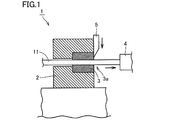
- FIG. 1 is a schematic cross-sectional view showing a structure of a cutting machine according to Embodiment 1.
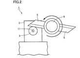
- FIG. It is a schematic side view which shows the structure of the cutting machine which concerns on Embodiment 1.
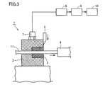
- FIG. It is a figure which shows schematically the structure of the damage detection apparatus which concerns on Embodiment 1.
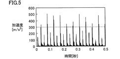
- FIG. 5 is a graph showing the amplitude of a pulse waveform when the cutting blade is normal when the cutting blade is normal in the cutting machine according to Embodiment 1; 4 is a graph showing the amplitude of a pulse waveform when a cutting blade is damaged in the cutting machine according to Embodiment 1.
- FIG. 6 is a graph showing the result of frequency analysis when the cutting blade is normal in the cutting machine according to Embodiment 1; 5 is a graph showing the result of frequency analysis when the cutting blade is broken in the cutting machine according to Embodiment 1. It is a figure which shows schematically the structure of the damage detection apparatus which concerns on Embodiment 2.
- FIG. It is a graph which shows the amplitude of a pulse waveform in case the cutting blade is normal in the cutting machine (it does not have a band filter) concerning Embodiment 2. It is a graph which shows the amplitude of the pulse waveform when the cutting blade is damaged in the cutting machine (no band filter) according to the second embodiment.
- a cold header machine 1 is for cutting a wire 11 that is an object to be cut into a predetermined length, and includes a holder 2, a die 3, a stopper 4, and a cutting blade 5 (cutting tool). And has mainly.
- the cold header machine 1 detects a vibration due to an impact generated when the wire 11 is cut by the cutting blade 5 and determines whether or not the cutting blade 5 is damaged (acceleration sensor 7).
- This breakage detection device is a blade breakage detection device according to the present embodiment, and its configuration will be described in detail later.
- the die 3 is mounted in the holder 2 and has a through hole (hole) through which the wire 11 passes in the center.
- the holder 2 holds the die 3 inside, and similarly has a through hole in the center for allowing the wire 11 to pass through.
- the die 3 and the holder 2 are arranged so that the through holes provided in the central portion communicate with each other. Thereby, the wire 11 sent to the die 3 is discharged from the outlet 3a and hits the stopper 4 to stop. As shown in FIG. 1, the stopper 4 is disposed at a distance from the die 3 on the outlet 3a side.
- the cutting blade 5 is provided in the vicinity of the outlet 3a. Referring to FIG. 2, the cutting blade 5 is connected to a rotating member 6 and is rotatable as indicated by an arrow in FIG. Thereby, the wire 11 discharged from the outlet 3 a of the die 3 and stopped by hitting the stopper 4 can be cut to a predetermined length by the cutting blade 5. Thus, when cutting the wire 11 with the cutting blade 5, vibration due to impact occurs, and the vibration varies depending on the state (normal or damaged) of the cutting blade 5.
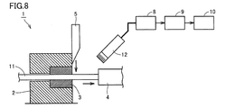
- the breakage detection apparatus is an apparatus for detecting breakage of a cutting tool for a cutting machine such as cold header machine 1, and includes an acceleration sensor 7 (detection unit), It mainly includes an amplifier 8, a band filter 9, and a determiner 10 (determination unit).
- the acceleration sensor 7 is attached to the upper surface of the holder 2.
- the acceleration sensor 7 converts vibration generated when the wire 11 is cut by the cutting blade 5 into an electric signal.
- This electric signal includes the amplitude of acceleration (the amplitude of the characteristic value) based on the vibration generated when the wire 11 is cut by the cutting blade 5.
- the amplifier 8 is connected to the acceleration sensor 7 and amplifies an electric signal generated in the acceleration sensor 7.
- the band filter 9 is connected to the amplifier 8.
- the band filter 9 extracts only the electric signal generated by the vibration in the predetermined frequency band (pass band) from the electric signals generated in the acceleration sensor 7 and transmits the extracted electric signal to the determiner 10.
- the pass band of the band filter 9 can be determined as follows. That is, the difference in frequency distribution between when the cutting blade 5 is normal and when it is damaged is confirmed in advance using an FFT (Fast Fourier Transform) analyzer or the like, and a frequency band having a large amplitude difference between normal and damaged is obtained. It can be determined as the pass band.
- the pass band determined as described above is, for example, not less than 1000 Hz and not more than 2000 Hz.
- the determiner 10 is connected to the band filter 9.
- the determiner 10 is for determining whether or not the cutting blade 5 is damaged based on the electrical signal generated in the acceleration sensor 7. More specifically, the determiner 10 determines the presence or absence of breakage in the cutting blade 5 based on the magnitude of the acceleration amplitude based on the vibration generated when the cutting blade 5 cuts.
- FIG. 4 and 5 are graphs showing the amplitude of acceleration of the pulse waveform on the time axis after passing through the band-pass filter 9. 4 and 5, the horizontal axis indicates time, and the vertical axis indicates the amplitude of acceleration (absolute value).
- FIG. 4 is a graph when both of the two cutting blades are normal, and
- FIG. 5 is a graph when one of the two cutting blades is broken.
- the amplitudes of the vibration pulses are all 300 m / s 2 (upper threshold) or less.
- a pulse having an amplitude of 300 m / s 2 or less corresponding to a normal cutting blade
- a pulse having an amplitude exceeding 300 m / s 2 breakage Equivalent to the cutting blade.
- the determination device 10 can determine that the cutting blade 5 has been damaged when the number of times that the amplitude exceeds 300 m / s 2 (upper limit threshold) exceeds a predetermined reference number.
- the upper limit threshold and the reference number are not particularly limited, and can be appropriately adjusted so that breakage of the cutting blade 5 can be detected with high sensitivity. Further, depending on the damaged state of the cutting blade 5, the amplitude at the time of breakage may be smaller than the amplitude at the normal time. In this case, the determiner 10 may determine that the cutting blade 5 has been damaged when the number of times the amplitude falls below the lower limit threshold exceeds a predetermined reference number.
- the acceleration sensor 7 generates an electrical signal based on the vibration generated when the cutting blade 5 cuts, and the determiner 10 based on the electrical signal.
- the presence or absence of breakage in the cutting blade 5 can be determined.
- the determination device 10 compares the electrical signal based on the vibration generated when the cutting blade 5 is normal and the electrical signal based on the vibration generated when the cutting blade 5 is damaged, thereby damaging the cutting blade 5. The presence or absence of can be determined. Therefore, according to the breakage detection device for a cutting tool according to the present embodiment, breakage in the cutting blade 5 of the cold header machine 1 can be detected with higher sensitivity.
- the acceleration sensor 7 generates an electrical signal that is an amplitude of acceleration based on the vibration generated when the cutting blade 5 cuts. After passing, the presence or absence of breakage of the cutting blade 5 is determined based on the magnitude of the amplitude. Thereby, the presence or absence of breakage of the cutting blade 5 can be determined by comparing the vibration amplitude when the cutting blade 5 is normal and the vibration amplitude when the cutting blade 5 is damaged. As a result, breakage in the cutting blade 5 of the cold header machine 1 can be detected with higher sensitivity.
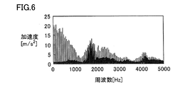
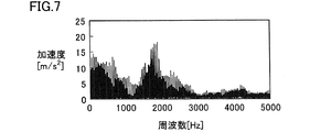
- FIG. 6 and 7 are graphs showing the results of frequency analysis of the electrical signal after passing through the amplifier 8.
- the horizontal axis indicates the frequency (Hz)
- the vertical axis indicates the acceleration (m / s 2 ).
- FIG. 6 is a graph when both of the two cutting blades are normal
- FIG. 7 is a graph when one of the two cutting blades is broken. Comparing the graphs of FIG. 6 and FIG. 7, when one cutting blade breaks, although an increase in acceleration is recognized in the frequency band of 1500 to 2000 Hz as compared with the normal time, the difference in pulse amplitude of the time axis waveform (FIG. 4 and FIG. 5), the difference is smaller.
- the breakage of the cutting blade 5 can be detected with higher sensitivity than the breakage detection by the frequency analysis.
- the breakage detection apparatus according to the second embodiment basically has the same configuration as the breakage detection apparatus according to the first embodiment, but includes an acoustic sensor 12 instead of the acceleration sensor 7 (see FIG. 1). Different. That is, the damage detection apparatus according to the second embodiment mainly includes the acoustic sensor 12 (detection unit), the amplifier 8, the band filter 9, and the determination unit 10 (determination unit).
- the cold header machine 1 according to the second embodiment basically has the same configuration as that of the cold header machine 1 according to the first embodiment, but differs in that it includes a damage detection apparatus according to the second embodiment.
- the acoustic sensor 12 is provided at a position facing each of the cutting blade 5, the holder 2, and the die 3 with a space therebetween.
- the acoustic sensor 12 converts vibration (sound) generated when the wire 11 is cut by the cutting blade 5 into an electrical signal.
- This electrical signal includes the amplitude (sound pressure) of the characteristic value based on the vibration (sound) generated when the wire 11 is cut by the cutting blade 5.
- the amplifier 8 is connected to the acoustic sensor 12 and amplifies an electrical signal generated in the acoustic sensor 12.
- the band filter 9 is connected to the amplifier 8.
- the band filter 9 extracts only the electric signal generated by the vibration in the predetermined frequency band (pass band) from the electric signals generated in the acoustic sensor 12, and transmits the extracted electric signal to the determiner 10.
- the pass band of the band filter 9 can be determined as follows. That is, a difference in frequency distribution between when the cutting blade 5 is normal and when it is damaged is confirmed in advance using an FFT analyzer or the like, and a frequency band having a large amplitude difference between normal and damaged is determined as the pass band. can do.
- the pass band determined as described above is, for example, 200 Hz to 1 kHz.
- the determiner 10 is connected to the band filter 9.
- the determiner 10 is for determining whether or not the cutting blade 5 is damaged based on an electrical signal generated in the acoustic sensor 12. More specifically, the determiner 10 determines whether or not the cutting blade 5 is damaged based on the amplitude of sound based on the vibration generated when the cutting blade 5 cuts.
- FIG. 9 and 10 are graphs showing the amplitude of the acoustic pulse (vibration pulse) on the time axis after passing through the amplifier 8.
- the horizontal axis indicates time (seconds), and the vertical axis indicates the amplitude Pa of the acoustic pulse.
- FIG. 9 is a graph when the cutting blade is normal, and FIG. 10 is a graph when the cutting blade is damaged.
- an upper limit threshold of an amplitude that is larger than the amplitude of the acoustic pulse when the cutting blade is normal and is equal to or smaller than the amplitude of the acoustic pulse when the cutting blade is damaged is provided in advance, and the measured amplitude is It can be determined that the cutting blade 5 has been damaged when the number of times the upper limit threshold has been exceeded exceeds a predetermined reference number.
- the upper limit threshold and the reference number are not particularly limited, and can be appropriately adjusted so that breakage of the cutting blade 5 can be detected with high sensitivity.
- the amplitude at the time of breakage may be smaller than the amplitude at the normal time.
- a lower limit threshold that is equal to or larger than the amplitude of the acoustic pulse when the cutting blade is broken and less than the amplitude of the acoustic pulse when the cutting blade is normal is set in advance, and the measured amplitude is It is also possible to determine that breakage has occurred in the cutting blade 5 when the number of times below the lower limit threshold exceeds a predetermined reference number.
- the acoustic sensor 12 generates an electrical signal based on the vibration generated when the cutting blade 5 cuts, and the determiner 10 determines the electrical signal based on the electrical signal.
- the presence or absence of breakage in the cutting blade 5 can be determined.
- the determination device 10 compares the electrical signal based on the sound generated when the cutting blade 5 is normal and the electrical signal based on the sound generated when the cutting blade 5 is damaged, whereby the damage in the cutting blade 5 is detected. The presence or absence of can be determined. Therefore, according to the cutting tool breakage detection apparatus according to the second embodiment, breakage in the cutting blade 5 of the cold header machine 1 can be detected with higher sensitivity by changing sound.
- the acoustic sensor 12 is in a position facing the cutting blade 5, the die 3, and the holder 2 with a space therebetween. Even if it does in this way, the vibration which generate
- the sensor 12 can be reached.
- the vibration can be detected with high sensitivity by the acoustic sensor 12. As a result, breakage in the cutting blade 5 can be detected with high sensitivity based on the vibration.
- the acoustic sensor 12 is preferably provided so that the distance from the cutting blade 5 can be changed. In this way, the sound pressure level of the sound detected by the acoustic sensor 12 can be adjusted by changing the distance between the acoustic sensor 12 and the cutting blade 5.
- the amplitude of the sound generated when the wire 11 is cut by the cutting blade 5 increases as the wire diameter (width along the cutting direction) of the wire 11 increases. Therefore, when cutting the wire 11 having a different wire diameter using the acoustic sensor 12 having a fixed distance from the cutting blade 5, the amplitude of the sound generated when the wire is cut is In some cases, it may be difficult to detect because it is not within the detection range.
- the breakage detection apparatus provided with such an acoustic sensor 12 can detect with high sensitivity the sound generated when the wire 11 is cut without depending on the wire diameter.
- the acoustic sensor 12 generates a signal based on the vibration generated when the cutting blade 5 cuts, and the determiner 10 increases the amplitude after passing through the band filter 9. Based on this, the presence or absence of breakage of the cutting blade 5 is determined. Thereby, the presence or absence of breakage of the cutting blade 5 can be determined by comparing the sound amplitude when the cutting blade 5 is normal and the sound amplitude when the cutting blade 5 is damaged. As a result, breakage in the cutting blade 5 of the cold header machine 1 can be detected with higher sensitivity.
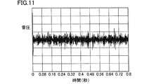
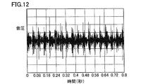
- FIG. 11 is a graph showing the amplitude of a pulse waveform when the cutting blade is normal in the cutting machine (including a band filter) according to the second embodiment.
- FIG. 12 is a graph showing the amplitude of the pulse waveform when the cutting blade is broken in the cutting machine (including the band filter) according to the second embodiment. 11 and 12, the horizontal axis indicates time (seconds), and the vertical axis indicates sound amplitude.
- FIG. 11 is a graph when the cutting blade is normal
- FIG. 12 is a graph when the cutting blade is damaged. Comparing the graphs of FIG. 11 and FIG.
- the cutting tool breakage detection apparatus and cutting machine of the present invention can be applied particularly advantageously in a cutting tool breakage detection apparatus that detects breakage of a cutting tool for a cutting machine and the cutting tool breakage detection apparatus.
Abstract
Cette invention concerne un dispositif de détection de rupture d'outil de coupe qui détecte la rupture d'une lame de coupe (5) d'une machine de matriçage à froid (1). Ledit dispositif de détection de rupture d'outil de coupe comprend : une unité de détection (7) qui génère un signal basé sur les vibrations se produisant pendant la coupe au moyen de la lame de coupe (5) ; et une unité de détermination (10) qui détermine si une rupture de la lame de coupe (5) est présente ou pas sur la base du signal généré à l'unité de détection (7).
Applications Claiming Priority (4)
| Application Number | Priority Date | Filing Date | Title |
|---|---|---|---|
| JP2014071856 | 2014-03-31 | ||
| JP2014-071856 | 2014-03-31 | ||
| JP2015-062165 | 2015-03-25 | ||
| JP2015062165A JP6653994B2 (ja) | 2014-03-31 | 2015-03-25 | 刃具の破損検出装置および切断機械 |
Publications (1)
| Publication Number | Publication Date |
|---|---|
| WO2015152203A1 true WO2015152203A1 (fr) | 2015-10-08 |
Family
ID=54240524
Family Applications (1)
| Application Number | Title | Priority Date | Filing Date |
|---|---|---|---|
| PCT/JP2015/060052 WO2015152203A1 (fr) | 2014-03-31 | 2015-03-31 | Dispositif de détection de rupture d'outil de coupe et machine à découper |
Country Status (2)
| Country | Link |
|---|---|
| JP (1) | JP6653994B2 (fr) |
| WO (1) | WO2015152203A1 (fr) |
Citations (3)
| Publication number | Priority date | Publication date | Assignee | Title |
|---|---|---|---|---|
| JPH09234621A (ja) * | 1996-02-28 | 1997-09-09 | Daido Kikai Seisakusho:Kk | ホーマーにおけるシャーダイの前方隙間調整装置 |
| JP2007222997A (ja) * | 2006-02-24 | 2007-09-06 | Mitsubishi Electric Corp | 工具異常検出装置及び工具異常検出システム |
| JP2010214508A (ja) * | 2009-03-16 | 2010-09-30 | Honda Motor Co Ltd | 円筒状ワーク切断装置と、切断用刃具の欠損判定方法 |
Family Cites Families (1)
| Publication number | Priority date | Publication date | Assignee | Title |
|---|---|---|---|---|
| JP2008208117A (ja) * | 2007-01-30 | 2008-09-11 | Kao Corp | 水性頭皮外用剤 |
-
2015
- 2015-03-25 JP JP2015062165A patent/JP6653994B2/ja not_active Expired - Fee Related
- 2015-03-31 WO PCT/JP2015/060052 patent/WO2015152203A1/fr active Application Filing
Patent Citations (3)
| Publication number | Priority date | Publication date | Assignee | Title |
|---|---|---|---|---|
| JPH09234621A (ja) * | 1996-02-28 | 1997-09-09 | Daido Kikai Seisakusho:Kk | ホーマーにおけるシャーダイの前方隙間調整装置 |
| JP2007222997A (ja) * | 2006-02-24 | 2007-09-06 | Mitsubishi Electric Corp | 工具異常検出装置及び工具異常検出システム |
| JP2010214508A (ja) * | 2009-03-16 | 2010-09-30 | Honda Motor Co Ltd | 円筒状ワーク切断装置と、切断用刃具の欠損判定方法 |
Also Published As
| Publication number | Publication date |
|---|---|
| JP6653994B2 (ja) | 2020-02-26 |
| JP2015199190A (ja) | 2015-11-12 |
Similar Documents
| Publication | Publication Date | Title |
|---|---|---|
| US8534128B2 (en) | Method and system for abnormality diagnosis of very low speed rotating machine | |
| TWI637169B (zh) | 刀具狀態檢測系統及其方法 | |
| JP6718107B2 (ja) | 作業機械の振動監視方法及びシステム | |
| JP6922405B2 (ja) | 振動抑制装置 | |
| US11313355B2 (en) | Method and apparatus for monitoring a wind turbine | |
| JPS61100348A (ja) | 工作機械監視装置、及び工具の破損事象を検出する方法 | |
| US7684935B2 (en) | Fiber cable cutting device | |
| CN105021706B (zh) | 一种砂轮破碎状态预警识别装置及方法 | |
| CN109708884B (zh) | 一种万向轴故障检测方法及设备 | |
| US9020778B2 (en) | Sensor based means of monitoring the mechanical condition of rotating machinery that operates intermittently | |
| WO2015152203A1 (fr) | Dispositif de détection de rupture d'outil de coupe et machine à découper | |
| JP6195234B2 (ja) | ろう付け物品の打音検査方法及びその装置 | |
| TW201334911A (zh) | 工具機斷刀自動偵測方法及其裝置 | |
| KR101494102B1 (ko) | 타이어 이상 감지 장치 | |
| KR101479292B1 (ko) | 회전기기의 베어링 마모 측정방법 및 그 장치 | |
| Potočnik et al. | Multisensory chatter detection in band sawing | |
| JP2011002276A (ja) | ガラス破壊検知方法および装置 | |
| JP2006300640A (ja) | キャビテーション検出方法 | |
| JP5495242B2 (ja) | 加工状態検出方法、加工状態検出プログラム、記録媒体、加工状態検出装置 | |
| CN105922847A (zh) | 用于检测玻璃面处的至少一个损伤事件的方法 | |
| JP4451714B2 (ja) | タイヤの破損状態推定方法とその装置 | |
| JP2015199190A5 (fr) | ||
| WO2011125233A1 (fr) | Dispositif de détection d'anomalie pour un équipement | |
| Vilcek et al. | Monitoring tool conditions for drilling | |
| Amin et al. | Acoustic Signature Based Early Fault Detection in Rolling Element Bearings |
Legal Events
| Date | Code | Title | Description |
|---|---|---|---|
| 121 | Ep: the epo has been informed by wipo that ep was designated in this application |
Ref document number: 15773845 Country of ref document: EP Kind code of ref document: A1 |
|
| NENP | Non-entry into the national phase | ||
| 122 | Ep: pct application non-entry in european phase |
Ref document number: 15773845 Country of ref document: EP Kind code of ref document: A1 |