WO2015146351A1 - 乗物用シートのテーブル - Google Patents
乗物用シートのテーブル Download PDFInfo
- Publication number
- WO2015146351A1 WO2015146351A1 PCT/JP2015/053975 JP2015053975W WO2015146351A1 WO 2015146351 A1 WO2015146351 A1 WO 2015146351A1 JP 2015053975 W JP2015053975 W JP 2015053975W WO 2015146351 A1 WO2015146351 A1 WO 2015146351A1
- Authority
- WO
- WIPO (PCT)
- Prior art keywords
- shaft member
- supported
- vehicle seat
- shaft
- support
- Prior art date
- Legal status (The legal status is an assumption and is not a legal conclusion. Google has not performed a legal analysis and makes no representation as to the accuracy of the status listed.)
- Ceased
Links
Images






Classifications
-
- B—PERFORMING OPERATIONS; TRANSPORTING
- B60—VEHICLES IN GENERAL
- B60N—SEATS SPECIALLY ADAPTED FOR VEHICLES; VEHICLE PASSENGER ACCOMMODATION NOT OTHERWISE PROVIDED FOR
- B60N3/00—Arrangements or adaptations of other passenger fittings, not otherwise provided for
- B60N3/10—Arrangements or adaptations of other passenger fittings, not otherwise provided for of receptacles for food or beverages, e.g. refrigerated
- B60N3/102—Arrangements or adaptations of other passenger fittings, not otherwise provided for of receptacles for food or beverages, e.g. refrigerated storable or foldable in a non-use position
-
- B—PERFORMING OPERATIONS; TRANSPORTING
- B60—VEHICLES IN GENERAL
- B60N—SEATS SPECIALLY ADAPTED FOR VEHICLES; VEHICLE PASSENGER ACCOMMODATION NOT OTHERWISE PROVIDED FOR
- B60N3/00—Arrangements or adaptations of other passenger fittings, not otherwise provided for
- B60N3/001—Arrangements or adaptations of other passenger fittings, not otherwise provided for of tables or trays
- B60N3/002—Arrangements or adaptations of other passenger fittings, not otherwise provided for of tables or trays of trays
- B60N3/004—Arrangements or adaptations of other passenger fittings, not otherwise provided for of tables or trays of trays of foldable trays mounted on the back-rest
Definitions
- the present invention relates to a vehicle seat table.
- the table is rotatably attached to a bracket 150 a disposed on the back surface of the seat back via a hinge pin 152.
- a leg portion 163 of a substantially U-shaped shaft 160 is rotatably attached to a bracket 150b provided at a lower portion of the bracket 150a.
- a support portion 180 and a lock member 170 that slidably support the tip portion 161 of the shaft 160 are provided on the back surface of the table main body 140.
- the support portion 180 is provided with an inclined groove 181, and the tip portion 161 of the shaft 160 slides back and forth in the inclined groove 181.
- the table main body 140 is displaced between the storage position facing the back surface of the seat back and the use position in a substantially horizontal state.
- the lock member 170 includes a guide groove 171 having a substantially L-shaped cross section cut by a surface perpendicular to the table body 140 and extending in the front-rear direction.
- the lock member 170 is supported by the table main body 140 so as to be pivotable in the vertical direction about the shaft pin 172 and urged clockwise.
- the longitudinal groove portion 171 b of the guide groove 171 coincides with the inclined groove 181 of the support portion 180.
- the operation portion 173 of the lock member 170 is pushed up, the horizontal groove portion 171a is aligned with the inclined groove 181 of the support portion 180 by rotating counterclockwise.
- the use position is a state in which the distal end portion 161 of the shaft 160 enters the longitudinal groove portion 171b of the lock member 170 and is held between the inclined groove 181 of the support portion 180.
- the operation portion 173 of the lock member 170 is pushed up in this state, the tip portion 161 of the shaft 160 moves from the vertical groove portion 171b of the lock member 170 to the horizontal groove portion 171a.
- the table main body 140 can be rotated.
- FIG. 11 shows a use position of the table main body 140 according to Japanese Patent Laid-Open No. 2001-246976.
- the tip portion 161 of the shaft 160 is held between the vertical groove portion 171 b of the lock member 170 and the inclined groove 181 of the support portion 180.
- the above configuration is configured such that the table main body 140 is not easily folded (not rotated toward the storage position).
- the applied load may become excessive.
- the tip portion 161 of the shaft 160 only pushes the rear side wall surface of the longitudinal groove portion 171b of the lock member 170 obliquely upward. Since the direction is held by the upper surface of the inclined groove 181 of the support portion 180, the lock member 170 does not move in the release direction. Eventually, either part will be destroyed.
- a table for a vehicle seat includes a table body that is pivotally mounted about a first axis with respect to one surface of the vehicle seat, and a table with respect to one surface of the vehicle seat.
- a shaft member is provided that is pivotable about two axes.
- the table main body is provided with a holding member that slidably holds a sliding portion that is a part of the shaft member, and the table main body is rotated by the shaft member so that one surface of the vehicle seat is provided. It is displaced between the storage position that is in a face-to-face manner and the use position that is in a substantially horizontal state.
- the shaft member includes the sliding portion that extends in parallel with the first axis, and a supported portion that extends in parallel with the first axis and is different from the sliding portion.
- the holding member that is in contact with the sliding portion and the support member that is in contact with the supported portion and is provided on the table main body are configured to be supported with respect to the table main body.
- the support of the shaft member with respect to the table main body can be released by moving the holding member with respect to the table main body.
- the support member is attached to the table body so as to release the support of the supported portion with respect to the table body when a predetermined load or more is applied to the table body from above in the use position. .
- the shaft member when the table main body is in the use position, the shaft member is supported with respect to the table main body, the sliding portion is in contact with the holding member, and the supported portion is in contact with the support member. Further, the release of the support state is performed by the movement of the holding member with respect to the table body. Thus, in a normal use state, the shaft member can be reliably supported on the table body unless the holding member is operated. At this time, if the table is accidentally touched, the support state is not released and the occurrence of inadvertent table folding can be suppressed. Further, when the load applied to the table body becomes equal to or greater than a predetermined value, the support member is attached so that the support of the supported portion of the shaft member to the table body is released. Thereby, even when an excessive load is applied, the possibility that the table is damaged can be suppressed.
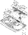
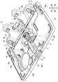
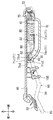
- FIG. 8 is a cross-sectional view taken along line VIII-VIII in FIG. It is sectional drawing showing the use position and storage position of a table, and the middle position. It is a schematic diagram of the table of the conventional vehicle seat. It is a figure which expands and shows the XI part of FIG.
- each direction of the vehicle when the table of the vehicle seat is attached to the vehicle together with the vehicle seat is indicated by an arrow.
- the description regarding the direction is made based on this direction.
- FIG. 1 shows a schematic configuration of a vehicle seat 10 to which a table 40 is attached.
- the vehicle seat 10 includes a seat back 20 that serves as a backrest and a seat cushion 30 that serves as a seating portion.
- a plate-like table 40 provided for use by a seated person of a rear side seat (not shown) is disposed on the back portion of the seat back 20.
- the table 40 is hinged to the back portion of the seat back 20 via the base plate 50 so as to be able to turn up and down. Due to the rotational movement, the storage position (indicated by the phantom line in the figure) folded so as to face the back portion of the seat back 20 and the use position raised from the storage position to a position that is substantially horizontal ( It is possible to move between the state (shown by a solid line).
- the base plate 50 is formed by integral molding of resin as shown in FIGS. 2 and 3, and reinforcing ribs 51 having a grid shape are formed over a wide area on the back surface thereof. Thereby, the base plate 50 has improved rigidity and strength against bending and twisting as a whole.
- shafts 52 for hinge-connecting the table 40 to the base plate 50 so as to be rotatable are provided at two places on one end side of the base plate 50. As shown in FIG. 3, the shaft 52 is fitted and hooked into two recessed hooks 41 formed at the rear end which is one end of the back surface of the table 40 described later, It can be rotated with respect to the hanging portion 41.
- the shaft 52 corresponds to a “first shaft” recited in the claims.
- two hook holes 53 for hooking two hook parts 63 on the upper end side of the shaft member 60 described later are formed on the back surface of the base plate 50.
- the left and right hook portions 63 of the shaft member 60 bent into an ⁇ -shape are inserted into the hook holes 53 while being supported by the metal plate 54.
- a main body 54a of the plate 54 is provided with a bent raised portion 54b having a V-shaped cross section and three mounting holes 54c, 54d, and 54e.
- the two hook portions 63 of the shaft member 60 are locked between the main body 54a of the plate 54 and the bent raised portion 54b, respectively.
- each hook 63 can be pivotally supported with respect to the base plate 50.
- Each hook 63 corresponds to a “second axis” recited in the claims.
- the base plate 50 is formed with a screw hole penetrating through the center of the four protrusions 55 d and 55 e (two each). As shown in FIG. 1, the screw hole is used to fasten and fix the seat back 20 with a screw (not shown). Thereby, as shown in FIGS. 1 and 7, the base plate 50 is assembled to the back surface portion of the seat back 20 while supporting the table 40 so as to be able to turn up and down around each shaft 52. Further, the base plate 50 is assembled to the back surface portion of the seat back 20 by supporting each hanging portion 63 of the shaft member 60 so as to be rotatable up and down around the hanging hole 53 in parallel with each shaft 52.
- the shaft member 60 is a member formed by bending a wire into an ⁇ shape. As shown in FIG. 3, a horizontally extending hook 63 that is rotatably attached to the base plate 50, an arm 64 that extends downward while bending from the center end of the table, and both arms
- the supported portion 62 extends from the lower end portion 64 toward the center of the table, and the sliding portion 61 connects the end portions of the supported portion 62 to each other.
- Both supported parts 62 are parallel to the hanging part 63 and are arranged farthest from the hanging part 63.
- the sliding portion 61 is also parallel to the hanging portion 63 and is disposed at a position slightly closer to the hanging portion 63 than the both supported portions 62. As will be described later, the sliding portion 61 is slidably held by the guide hole 71 of the holding member 70. Further, both supported portions 62 are supported by being pressed against the support member 80 at the use position of the table 40.
- the table 40 is formed by integral molding of resin, and on the back surface thereof, reinforcing ribs 42 having a continuous shape in a lattice shape are formed over a wide area. Thereby, the table 40 has enhanced rigidity and strength against bending and twisting as a whole.
- a holding member 70 capable of slidably linking the sliding portion 61 of the shaft member 60 is provided at the center of the back surface 40b of the table 40.
- the holding member 70 is a substantially rectangular member in plan view.
- the holding member 70 includes a guide hole 71 that extends in the longitudinal direction in a central section in the longitudinal direction and penetrates in a direction perpendicular to the longitudinal direction to slidably hold the sliding portion 61 of the shaft member 60.
- the guide hole 71 includes a parallel portion 71 a extending from one end in parallel to the bottom surface 71 d in the central section in the longitudinal direction, and an inclined portion 71 b extending from the end portion of the parallel portion 71 a while approaching the bottom surface 71 d.
- the upper surface 71c1 extends in parallel with the bottom surface 71d, and the lower surface 71c2 has a terminal portion 71c that extends close to the bottom surface 71d. That is, the distance between the upper surface 71c1 and the lower surface 71c2 of the terminal portion 71c gradually decreases, and the other end portion is shorter than the diameter of the sliding portion 61 of the shaft member 60.
- an operation portion 72 is provided at an end portion (rear end portion) on one end side of the guide hole 71 of the holding member 70.
- the operation portion 72 is configured to protrude to the center of the rear end portion of the table 40 through an operation portion through hole 43 provided in the center of the rear end portion of the table 40.
- a pair of guided portions 73 are provided in the vicinity of the front end portion of the holding member 70 in contact with the extended surface of the bottom surface 71d.
- the guided portion 73 is sandwiched between the guide portion 44 provided at the center of the back surface 40b of the table 40 and the back surface 40b of the table 40, and can slide in the front-rear direction of the table 40 with respect to the table 40.
- a pair of left and right spring receiving portions 74 are provided at both ends in the left and right direction of the operation portion 72 of the holding member 70 so as to contact the extended surface of the bottom surface 71d.
- the operation portion 72 is passed through the operation portion through hole 43, the guided portion 73 is positioned between the guide portion 44 and the back surface 40 b of the table 40, and the holding member 70 is moved in the front-rear direction with respect to the back surface 40 b of the table 40. Install slidably.
- a pair of springs 75 is disposed between the pair of standing wall portions 45 provided on the back surface 40 b of the table 40 and the spring receiving portion 74.
- the spring 75 applies a force in a direction to separate the standing wall portion 45 and the spring receiving portion 74 from each other, the holding member 70 is urged backward with respect to the table 40.
- the state of the holding member 70 is a state at the use position of the table 40 as shown in FIG.
- the sliding portion 61 of the shaft member 60 is located at the terminal portion 71 c of the guide hole 71.
- the sliding portion 61 is in contact with the terminal portion 71c at two upper and lower points of the upper surface 71c1 and the lower surface 71c2. Supported by immobility.
- two support members 80 are provided on the left and right sides of the holding member 70 on the back surface 40 b of the table 40.
- the support member 80 presses and supports the supported portion 62 of the shaft member 60 in the forward direction at the use position of the table 40.
- the support member 80 is a substantially rectangular parallelepiped member, and is attached to the back surface 40b of the table 40 so as to be slidable in the front-rear direction.
- the cross section perpendicular to the back surface 40b of the table 40 in the front-rear direction of the support member 80 is an inclined surface 81 whose surface abutting the supported portion 62 of the shaft member 60 is slightly inclined downward and rearward. Is formed.
- the inclination of the inclined surface 81 is determined when the force pressing the supported portion 62 of the shaft member 60 against the support member 80 is released, that is, when the holding member 70 slides forward, the supported portion of the shaft member 60. 62 is for facilitating separation from the inclined surface 81 of the support member 80. As shown in FIG. 8, the supported portion 62 of the shaft member 60 is pressed against the inclined surface 81 of the support member 80 by the urging force applied from the terminal portion 71 c of the holding member 70 through the sliding portion 61 of the shaft member 60. The state in which the table 40 is in contact is the state where the table 40 is used.
- the supported portion 62 of the shaft member 60 is supported at a single point on the inclined surface 81 in a section cut by a plane perpendicular to the hinge shaft 52 and perpendicular to the back surface 40b of the table 40. Is done. Further, the support member 80 is pressed with a rear surface portion 82 opposite to the inclined surface 81 forward by a spring 83.
- the spring 83 is disposed between the rear surface portion 82 and a surface opposite to the spring 75 of the pair of standing wall portions 45 provided on the back surface 40 b of the table 40.
- the spring 83 has a higher spring constant than the spring 75.
- the support member 80 is supported in a substantially non-moving state.
- a relatively strong force is applied to the surface side of the table 40 at the use position, such as carelessly, a strong pressing force is applied to the support member 80 via the supported portion 62 of the shaft member 60.
- the spring 83 contracts to allow the support member 80 to slide backward. This can prevent the holding member 70, the table 40, the base plate 50, and the like from being damaged.
- the holding member 70 slides forward along the back surface 40 b of the table 40 by overcoming the urging force of the spring 75 by pushing the operation portion 72 of the holding member 70 forward. Move.
- the sliding portion 61 of the shaft member 60 is displaced from the terminal portion 71c of the guide hole 71 to the inclined portion 71b, and the support in the vertical direction is released.
- the urging force applied through the sliding portion 61 of the shaft member 60 releases the force that presses the supported portion 62 of the shaft member 60 against the supporting member 80, so that the supported portion 62 is inclined with respect to the supporting member 80. Move away from surface 81.
- the sliding portion 61 of the shaft member 60 rotates around the hook portion 63 with respect to the base plate 50 while sliding the guide hole 71 from the inclined portion 71b to the parallel portion 71a.
- the sliding portion 61 of the shaft member 60 is located at the end of the parallel portion 71 a of the guide hole 71.
- a cup holder 90 is attached to the back surface 40b of the table 40 so as to be able to fall down.
- the two rotation shafts 91 provided on the cup holder 90 are attached by being fitted into the two locking portions 46 provided on the back surface 40b of the table 40.
- the cup can be held between the cup support portion 92 and the opening 40 d of the table 40.
- lid members 49a and 49b are attached to the back surface 40b of the table 40 by vibration welding so as to cover the portions where the reinforcing ribs 42 are formed. Thereby, the appearance of the back side of the table 40 is kept well.
- hooks 40c that can hook and hold shopping bags or the like are provided at two left and right ends of the table 40.
- a lock member 100 is assembled to the locking portion 47 provided at the upper portion of the center of the back surface 40 b of the table 40.
- the lock member 100 elastically hooks the arm portion 64 of the shaft member 60 and holds the pivoting motion in a restricted state.
- the lock member 100 is disposed at a position between two resin-made guide walls 48 that are formed so as to protrude from the center of the back surface 40b of the table 40 so as to face each other.
- the lock member 100 includes a resin claw portion 101 that protrudes toward each guide wall 48.
- the lock member 100 has a case portion 102 which is a main body formed by integral molding of resin.
- the case portion 102 is formed in a shape in which the inside is hollow and the upper portion and both side portions communicate with each other and open.
- the case part 102 is assembled in a state in which the claw parts 101 are respectively inserted into the opening parts on both sides thereof.
- the claw portions 101 are configured to be elastically connected to each other via the compression spring 103 by being provided with a compression spring 103 and hooked therebetween.
- a receiving port that can receive the arm portion 64 of the shaft member 60 is formed between the lock member 100 and each guide wall 48. Yes. And each nail
- the arm portion 64 of the shaft member 60 is pushed into the receiving port, the upper inclined surface 101a is pressed, and the claw portions 101 move in directions approaching each other. Accordingly, the movement until the arm portion 64 of the shaft member 60 contacts the pedestal surface 102a of the case portion 102 is allowed.
- each claw portion 101 When the arm portion 64 of the shaft member 60 comes into contact with the pedestal surface 102a of the case portion 102, each claw portion 101 returns to a state where it is elastically supported in the original receiving port. Accordingly, each claw portion 101 supports the arm portion 64 of the shaft member 60 by the lower inclined surface 101b. This state is the storage position of the table 40. When the table 40 is rotated from the storage position to the use position, each claw portion 101 of the lock member 100 performs the reverse operation.
- the embodiment configured as described above has the following operational effects.
- the sliding portion 61 of the shaft member 60 is located at the terminal portion 71 c of the guide hole 71 of the holding member 70.
- the sliding portion 61 is supported by the terminal portion 71 c of the holding member 70 so as to be immovable in the vertical direction on the table 40 side, and the supported portion 62 is It is pressed against the inclined surface 81 of the support member 80 and is supported so as not to move forward and backward. Accordingly, the table 40 is supported by the shaft member 60 so as not to rotate with respect to the base plate 50.
- the upper surface of the table 40 can be used as a table.
- the shaft member 60 is supported with respect to the table 40 with a strength that does not cause an inadvertent folding operation in a normal use state, the shaft member 60 is not folded to the extent that the hand is accidentally attached.
- the support member 80 that supports the supported portion 62 of the shaft member 60 compresses and slides the spring 83 to slide. Is configured to open. Thereby, damage to the table 40 can be prevented.
- the table 40 loses support of the shaft member 60, and is centered on the hinge shaft 52 with respect to the base plate 50, from the use position (A) indicated by the solid line to the intermediate position indicated by the virtual line ( It rotates to the storage position (C) via B).
- the sliding portion 61 of the shaft member 60 slides on the guide hole 71 from the inclined portion 71b to the parallel portion 71a, and is located halfway from the use position (A) with the hook portion 63 as the center with respect to the base plate 50. It rotates to the storage position (C) via (B).
- each claw portion 101 In the storage position (C), when the arm portion 64 of the shaft member 60 is pushed into the receiving port between the lock member 100 and each guide wall 48, the claw portions 101 are moved in the directions approaching each other and moved forward. It enters and comes into contact with the pedestal surface 102 a of the case portion 102. When the arm portion 64 of the shaft member 60 comes into contact with the pedestal surface 102a of the case portion 102, each claw portion 101 returns to a state where it is elastically supported in the original receiving port, and supports the arm portion 64 of the shaft member 60. .
- the sliding portion 61 of the shaft member 60 is disposed on the side slightly closer to the hanging portion 63 than the supported portion 62.
- the sliding portion 61 may be disposed on the side slightly away from the hanging portion 63 from the supported portion 62, or the sliding portion 61 and the supported portion 62 may be disposed linearly. .
- the support member 80 is attached to the table 40 via the spring 83. It may replace with this and may attach via elastic bodies, such as rubber and an elastomer.
- the lock member 100 that elastically locks and unlocks the lock of the shaft member 60 with respect to the table 40 in the storage position is used.
- a type that requires operation of the operation unit 72 such as a lock mechanism in the use position may be used.
- the present invention may be applied to a seat back side surface, a seat cushion side surface, or the like, or may be applied to a seat mounted on a ship, a train, an airplane, or the like other than an automobile.
Landscapes
- Engineering & Computer Science (AREA)
- Transportation (AREA)
- Mechanical Engineering (AREA)
- Physics & Mathematics (AREA)
- Thermal Sciences (AREA)
- Chair Legs, Seat Parts, And Backrests (AREA)
- Passenger Equipment (AREA)
- Vehicle Step Arrangements And Article Storage (AREA)
Abstract
乗物用シート(10)の背面に、回動自在にテーブル(40)とシャフト部材(60)が取付けられ、シャフト部材(60)の摺動部(61)を、保持部材(70)のガイド孔(71)に摺動可能に支持する。使用位置(A)において、シャフト部材(60)は、保持部材(70)のガイド孔(71)の端末部(71c)に摺動部(61)が当接するとともに、被支持部(62)が支持部材(80)に押圧された状態で、支持されている。テーブル(40)に上から所定以上の荷重が加えられたとき、支持部材(80)は移動してシャフト部材(60)の支持を解除するように、テーブル(40)に対してバネ(83)を介して取り付けられている。
Description
本発明は、乗物用シートのテーブルに関する。
乗物用シートのテーブルとして、特開2001-246976号公報に記載のものがある。このテーブルは、図10及び図11に示すように、シートバックの裏面に配設したブラケット150aに対して、ヒンジピン152を介して回動自在に取付けられている。ブラケット150aの下部に設けられたブラケット150bに対して、略U字状のシャフト160の脚部163が回動自在に取付けられている。テーブル本体140の裏面にはシャフト160の先端部161を摺動可能に支持する支持部180とロック部材170が設けられている。支持部180には傾斜溝181が設けられていて、シャフト160の先端部161が傾斜溝181中を前後に摺動する。これにより、テーブル本体140が、シートバック裏面に対面状となる収納位置と、略水平状態となる使用位置との間を変位する。
ロック部材170は、図11に示すように、テーブル本体140に垂直で前後方向に延びる面で切った断面が、略L字状のガイド溝171を有する。ロック部材170は、軸ピン172を中心に上下方向に回動可能に、かつ、時計回り方向に付勢されてテーブル本体140に支持されている。ロック部材170は、非操作時においてガイド溝171の縦溝部171bが支持部180の傾斜溝181に一致している。ロック部材170の操作部173を押し上げると反時計回りに回動して横溝部171aが支持部180の傾斜溝181に一致する。シャフト160の先端部161が、ロック部材170の縦溝部171bに入って、支持部180の傾斜溝181との間で保持されている状態が使用位置である。この状態でロック部材170の操作部173を押し上げるとシャフト160の先端部161がロック部材170の縦溝部171bから横溝部171aに移動する。これにより、テーブル本体140の回動動作が可能となる。
図11は、特開2001-246976号公報にかかる、テーブル本体140の使用位置を示している。この使用位置では、シャフト160の先端部161が、ロック部材170の縦溝部171bと支持部180の傾斜溝181との間で保持されている。テーブル本体140に誤って手をつく等して比較的大きい荷重がテーブル本体140に印加される場合がある。この荷重に対して上記構成は、容易にテーブル本体140が、折りたたまれない(収納位置に向かって回動しない)ように構成されている。しかし、印加される荷重が過大なものになる場合がある。この場合、シャフト160の先端部161は、ロック部材170の縦溝部171bの後側壁面を斜め上方に向かって押すのみである。その方向は支持部180の傾斜溝181の上面で保持されているのでロック部材170が解除方向に動くことはない。そして、最終的にはいずれかの部分が破壊してしまうことになる。
従来、テーブル使用位置において、不用意なテーブルの折り畳み発生を防止することができるテーブルが必要とされている。過大な力が印加された場合には破損を防止することができるテーブルが必要とされている。
本発明の1つの特徴によると、乗物用シートのテーブルは、乗物用シートの一面に対して第一軸を中心に回動自在に取付けたテーブル本体と、前記乗物用シートの一面に対して第二軸を中心に回動自在に取付けたシャフト部材を備える。前記テーブル本体に、前記シャフト部材の一部である摺動部を、摺動可能に保持する保持部材を設けて、前記テーブル本体が、前記シャフト部材の回動動作により、前記乗物用シートの一面に対面状となる収納位置と、略水平状となる使用位置との間を変位する。前記シャフト部材は、前記第一軸と平行に延びる前記摺動部と、前記第一軸と平行に延びるとともに該摺動部とは異なる被支持部を有する。前記使用位置において、前記摺動部に当接する前記保持部材と、前記被支持部に当接する、前記テーブル本体に設けられた支持部材とで、前記テーブル本体に対して支持されるよう構成されている。前記使用位置における、通常の使用状態においては、前記保持部材を前記テーブル本体に対して移動させることによって、前記テーブル本体に対する前記シャフト部材の支持を解除できるよう構成されている。前記支持部材は、前記使用位置において、前記テーブル本体に上から所定以上の荷重が加えられた場合、前記テーブル本体に対する前記被支持部の支持を開放するように、前記テーブル本体に取り付けられている。
したがって、テーブル本体が使用位置にあるとき、テーブル本体に対してシャフト部材を、摺動部は保持部材に当接させ、被支持部は支持部材に当接させて支持する。また、この支持状態の解除は保持部材のテーブル本体に対する移動によって行われる。これによって、通常の使用状態では保持部材を操作しない限りシャフト部材のテーブル本体に対する支持を確実なものとできる。このとき、テーブルに誤って手をつく程度では支持状態の解除は行われず不用意なテーブル折り畳みの発生を抑制できる。また、テーブル本体に加えられる荷重が、所定以上となったときは、シャフト部材の被支持部のテーブル本体に対する支持が開放されるように、支持部材が取付けられている。これによって、過大な荷重が加えられたときでもテーブルが破損されるおそれを抑制できる。
本発明の1つの実施の形態を図1~9にしたがって説明する。各図中、矢印により乗物用シートのテーブルが乗物用シートとともに乗物に取付けられたときの乗物の各方向を示している。以下の説明において、方向に関する記述は、この方向を基準として行うものとする。
図1には、テーブル40が取付けられた乗物用シート10の概略構成が示されている。乗物用シート10は、背凭れとなるシートバック20と、着座部となるシートクッション30とを有する。シートバック20の背面部に、後部側シート(不図示)の着座者の使用に供される板状のテーブル40が配設されている。
テーブル40は、ベース板50を介してシートバック20の背面部に起倒回動可能にヒンジ結合されている。その回動運動によって、シートバック20の背面部に対面状となるように畳み込まれた収納位置(図示仮想線状態)と、この収納位置からほぼ水平となる位置まで起こし上げられた使用位置(図示実線状態)との間を移動できるようになっている。
ベース板50は、図2及び図3に示すように、樹脂の一体成形によって形成されており、その裏面部には、格子状に連なった形状の補強リブ51が広い領域にわたって形成されている。これにより、ベース板50は、全体としての曲げやねじりに対する剛性および強度が高められている。このベース板50の一端側の2箇所には、ベース板50に対してテーブル40を回動可能にヒンジ連結するための軸52が設けられている。この軸52は、図3に示されるように、後述するテーブル40の裏面一端部である後端部に形成された2箇所の凹状の掛部41に嵌め込まれて掛着されることにより、各掛部41に対して回動可能とされている。この軸52が、特許請求の範囲記載の「第一軸」に相当する。
ベース板50の裏面部には、図3に示すように、後述するシャフト部材60の上端側の2箇所の掛部63を掛け入れるための2箇所の掛孔53が形成されている。これらの掛孔53には、Ω字状に折り曲げられたシャフト部材60の左右の掛部63が、金属製のプレート54に支持されながら挿入される。プレート54の本体54aには断面がV字状の曲げ起こし部54bと3つの取付用の孔54c,54d,54eが設けられている。シャフト部材60の2箇所の掛部63をそれぞれプレート54の本体54aと曲げ起こし部54bの間に係止させる。この状態で、プレート54の取付用の孔54c,54d,54eをベース板50裏面の突起部55c,55d,55eにそれぞれ合わせて挿入する。次に突起部55cを熱を加えて溶かしてかしめる(熱溶着する)。これによって、各掛部63をベース板50に対し回動可能に軸支した状態にできる。この各掛部63が、特許請求の範囲記載の「第二軸」に相当する。
ベース板50は、図3に示すように、その4箇所の突起部55d,55e(各2箇所ずつ)の中央にビス孔が貫通して形成されている。図1に示すように、このビス孔を利用して、シートバック20の背面部に対してビス(不図示)により締め付けられて固定されている。これにより、ベース板50は、図1及び図7に示すように、テーブル40を各軸52のまわりに起倒回動可能に支持してシートバック20の背面部に組み付けられている。
また、ベース板50は、シャフト部材60の各掛部63を掛孔53のまわりに各軸52と平行に起倒回動可能に支持してシートバック20の背面部に組み付けられている。
また、ベース板50は、シャフト部材60の各掛部63を掛孔53のまわりに各軸52と平行に起倒回動可能に支持してシートバック20の背面部に組み付けられている。
シャフト部材60は、ワイヤをΩ字状に折り曲げて形成した部材である。図3に示すように、ベース板50に対して回動可能に取付けられる左右方向に延びる掛部63と、そのテーブル中央側端部から曲折しながら下方向に延びる腕部64と、両腕部64の下端部からテーブル中央に向かって延びる被支持部62と、被支持部62の端部同士を繋ぐ摺動部61と、から構成される。両被支持部62は、掛部63と平行で、掛部63から最も離間して配設されている。摺動部61も掛部63と平行で、両被支持部62よりやや掛部63に近い位置に配設されている。後述のように摺動部61は保持部材70のガイド孔71によって摺動可能に保持されている。また、両被支持部62は、テーブル40の使用位置において支持部材80に押し当てられて支持される。
テーブル40は、図4に示すように、樹脂の一体成形によって形成されており、その裏面部には、格子状に連なった形状の補強リブ42が広い領域にわたって形成されている。これにより、テーブル40は、全体としての曲げやねじりに対する剛性および強度が高められている。
テーブル40の裏面40b中央部には、シャフト部材60の摺動部61をスライド可能にリンク連結させることのできる保持部材70が設けられている。この保持部材70は、平面視で略矩形状の部材である。保持部材70は、長手方向の中央断面において長手方向に延び、長手方向に垂直な方向に貫通してシャフト部材60の摺動部61をスライド可能に保持するガイド孔71を備える。ガイド孔71は、図8に示すように、長手方向の中央断面において一端から底面71dに平行に延びる平行部71aと、平行部71aの端部から底面71dに近接しつつ延びる傾斜部71bと、傾斜部71bの端部からガイド孔71の他の端部まで、上面71c1が底面71dに平行に延び、下面71c2が底面71dに近接しつつ延びる端末部71cを有する。すなわち、端末部71cの上面71c1と下面71c2の間隔は漸次減少し、他の端部においては、シャフト部材60の摺動部61の直径より短くなっている。図5に示すように、保持部材70のガイド孔71の一端側の端部(後端部)には操作部72が設けられている。操作部72は、テーブル40の後端部中央に設けられた操作部通し孔43を通してテーブル40の後端部中央に突出させられるよう構成されている。また、被案内部73が、保持部材70の前端部近傍に底面71dの延長面に接して左右一対設けられている。被案内部73は、テーブル40の裏面40b中央部に設けられた案内部44とテーブル40の裏面40bとの間にはさまれて、テーブル40に対して、テーブル40の前後方向に摺動可能に保持される。また、保持部材70の操作部72の左右方向両端には外側に張り出してバネ受け部74が底面71dの延長面に接して左右一対設けられている。操作部72を操作部通し孔43に通すとともに、被案内部73を案内部44とテーブル40の裏面40bとの間に位置させて、保持部材70をテーブル40の裏面40bに対して前後方向に摺動可能に取付ける。このとき、テーブル40の裏面40bに設けられた一対の立ち壁部45とバネ受け部74との間に一対のバネ75が配設される。このバネ75が立ち壁部45とバネ受け部74との間を引き離す方向に力を加えることによって、保持部材70はテーブル40に対し後方向に付勢される。これによって、操作部72はテーブル40の外側に向かって付勢されながらその動きがテーブル40の操作部通し孔43外周によって止められている。この保持部材70の状態が、図8に示すように、テーブル40の使用位置における状態である。このとき、シャフト部材60の摺動部61は、ガイド孔71の端末部71cに位置している。この状態で、摺動部61は、軸52に垂直で、かつテーブル40の裏面40bに垂直な面で切断した断面において、端末部71cに上面71c1と下面71c2の上下2点で当接して上下不動に支持される。
テーブル40の裏面40bにおいて、図4及び図5に示すように、保持部材70の左右両側部には、支持部材80が2個設けられている。支持部材80は、テーブル40の使用位置においてシャフト部材60の被支持部62を前方向に押圧支持する。支持部材80は、略直方体状の部材で、テーブル40の裏面40bに対して前後方向に摺動可能に取付けられている。支持部材80の前後方向のテーブル40の裏面40bに垂直な断面は、図8に示すように、シャフト部材60の被支持部62に当接する面が下後方に向かってわずかに傾く傾斜面81として形成されている。この傾斜面81の傾きは、シャフト部材60の被支持部62を支持部材80に押しつける力が解除されたとき、すなわち、保持部材70が前方に摺動したときに、シャフト部材60の被支持部62が支持部材80の傾斜面81から離れ易くするためのものである。図8に示すように、シャフト部材60の被支持部62が、保持部材70の端末部71cからシャフト部材60の摺動部61を通して印加される付勢力で、支持部材80の傾斜面81に押圧され当接している状態が、テーブル40の使用位置における状態である。このとき、シャフト部材60の被支持部62は、ヒンジ軸52に垂直で、かつテーブル40の裏面40bに垂直な面で切断した断面において、傾斜面81に1点で当接して前後不動に支持される。また、支持部材80は、傾斜面81と反対側の後面部82をバネ83により前方に向けて押圧されている。バネ83は、後面部82と、テーブル40の裏面40bに設けられた一対の立ち壁部45のバネ75と反対側の面との間に配設されている。バネ83は、バネ75に比べてよりバネ定数の高いものとされている。したがって、通常の保持部材70の摺動操作によるテーブル40の使用位置へのロック、アンロックの切り換え動作においてはほとんど伸縮せず、支持部材80をほぼ不動状態に支持している。使用位置におけるテーブル40の表面側に不用意に手をつく等して比較的強い力が印加されたとき、シャフト部材60の被支持部62を介して支持部材80には強い押圧力が加えられる。このとき、バネ83は縮んで支持部材80の後方向への摺動を許容する。これによって、保持部材70、テーブル40、ベース板50等が破損するのを防止できる。
図8に示すテーブル40の使用位置において、保持部材70の操作部72を前方向に押すことによって保持部材70は、バネ75の付勢力に打ち勝ちながら前方へ、テーブル40の裏面40bに沿って摺動する。このとき、シャフト部材60の摺動部61は、ガイド孔71の端末部71cから傾斜部71bに変位して上下方向の支持が解除される。また同時に、シャフト部材60の摺動部61を通して印加される付勢力が、シャフト部材60の被支持部62を支持部材80に押しつける力が解除されるので、被支持部62は支持部材80の傾斜面81から離れる。こののち、シャフト部材60の摺動部61は、ガイド孔71を傾斜部71bから平行部71aにかけて摺動しつつ、ベース板50に対し掛部63を中心に回動する。そして、収納位置において、シャフト部材60の摺動部61は、ガイド孔71の平行部71aの端部に位置する。
図3に示すように、テーブル40の裏面40bには、さらに、カップホルダ90が倒伏可能に取付けられている。カップホルダ90に設けられた2つの回動軸91を、テーブル40の裏面40bに設けられた2つの係止部46に嵌め込むことによって取付けられる。カップホルダ90を回動させてテーブル40の裏面40bから起こし上げたとき、カップ支持部92とテーブル40の開口部40dとの間でカップが保持できるようになっている。図4に示すように、テーブル40の裏面40bには、補強リブ42が形成された部分を覆い隠す蓋部材49a、49bが振動溶着によって取付けられている。これによって、テーブル40の裏面側の見栄えが良く保たれる。カップホルダ90を畳み込むと収納位置となり、蓋部材49a、49bと面一の状態となって、テーブル40をシートバック20の背面部に対して収納位置としたときじゃまにならないようになっている。さらにテーブル40の左右両端部には買い物袋等を引っ掛けて保持することができる引っ掛け部40cが2箇所に設けられている。
図3に示すように、テーブル40の裏面40b中央の上方部に設けられた係止部47には、ロック部材100が組み付けられている。ロック部材100は、テーブル40を収納位置に回動移動させたときに、シャフト部材60の腕部64を弾性的に掛着させてその回動運動を規制した状態に保持する。このロック部材100は、テーブル40の裏面40b中央部に互いに向かい合うようにして突出形成された樹脂製の2枚のガイド壁48の間の位置に配置されている。ロック部材100は、各ガイド壁48に向かって張り出す樹脂製の爪部101を有している。
図6に示すように、ロック部材100は、その本体となるケース部102が、樹脂の一体成形によって形成されている。ケース部102は、その内部が中空となって上部と両側部とが連通して開口した形状となって形成されている。ケース部102には、その両側部の開口部分に、それぞれ爪部101が差し込まれた状態となって組み付けられている。これら爪部101は、互いの間に圧縮バネ103が設けられて掛着されることにより、圧縮バネ103を介して互いに弾性的に連結された構成となっている。
図2及び図7に示すように、ロック部材100の設置によって、ロック部材100と各ガイド壁48との間には、それぞれシャフト部材60の腕部64を受け入れることができる受け入れ口が形成されている。そして、これらの受け入れ口内にロック部材100の各爪部101が弾性的に支えられた状態となって保持されている。シャフト部材60の腕部64が受け入れ口に押し入れられると、上側傾斜面101aが押圧されて、各爪部101は互いに接近する方向に移動する。これによって、シャフト部材60の腕部64がケース部102の台座面102aに当接するまでの動きを許容する。シャフト部材60の腕部64がケース部102の台座面102aに当接したとき、各爪部101は元の受け入れ口内に弾性的に支えられた状態に戻る。これによって、各爪部101は、シャフト部材60の腕部64を下側傾斜面101bによって支持する。この状態が、テーブル40の収納位置となる。テーブル40を収納位置から使用位置に回動動作させるときは、ロック部材100の各爪部101は上記の逆の動作を行う。
以上のように構成される実施形態は、以下のような作用効果を奏する。テーブル40の使用位置(図1の実線状態及び図9の(A))では、シャフト部材60の摺動部61は保持部材70のガイド孔71の端末部71cに位置する。このとき、ベース板50に対して回動可能に支持されたシャフト部材60は、テーブル40側において、摺動部61が保持部材70の端末部71cに上下不動に支持され、被支持部62が支持部材80の傾斜面81に押圧されて前後不動に支持される。これによって、テーブル40は、シャフト部材60によってベース板50に対して回動不能に支持される。この状態でテーブル40の上面はテーブルとして使用可能となる。このとき、シャフト部材60は通常の使用状態では不用意な折り畳み動作が生じない強度でテーブル40に対して支持されているので、誤って手をついたりする程度では折り畳まれることはない。しかし、テーブル40が破損するおそれのある程度の所定以上の力が加えられた場合には、シャフト部材60の被支持部62を支持する支持部材80がバネ83を圧縮して摺動しシャフト部材60を開放するように構成されている。これによって、テーブル40の破損が防止できる。
次に、テーブル40の後方に配設された保持部材70の操作部72を前方向に押すと、保持部材70が前方に摺動してシャフト部材60の摺動部61をガイド孔71の端末部71cから開放する。同時に、シャフト部材60の被支持部62を支持部材80に押しつける力が解除されるので、被支持部62は支持部材80の傾斜面81から離れる。この使用位置におけるテーブル40のロック状態の解除は、保持部材70の操作部72を前方向に押すことにより行うことができる。これによって、シャフト部材60等他の部材を同時に操作する必要がなく操作が簡便である。こののち、テーブル40は、図9に示すように、シャフト部材60の支持を失い、ベース板50に対しヒンジ軸52を中心に、実線で示す使用位置(A)から仮想線で示す途中位置(B)を経て収納位置(C)まで回動する。このとき、シャフト部材60の摺動部61は、ガイド孔71を傾斜部71bから平行部71aにかけて摺動しつつ、ベース板50に対し掛部63を中心に、使用位置(A)から途中位置(B)を経て収納位置(C)まで回動する。収納位置(C)において、シャフト部材60の腕部64は、ロック部材100と各ガイド壁48との間の受け入れ口に押し入れられると、各爪部101を互いに接近する方向に移動させて前方向に入り込み、ケース部102の台座面102aに当接する。シャフト部材60の腕部64がケース部102の台座面102aに当接すると、各爪部101は元の受け入れ口内に弾性的に支えられた状態に戻り、シャフト部材60の腕部64を支持する。
テーブル40を、収納位置(C)から使用位置(A)に変位させるときは上記の操作と逆の操作を行う。すなわち、収納位置(C)にあるテーブル40をヒンジ軸52を中心に回動させると、シャフト部材60の腕部64がロック部材100の各爪部101を押し開いて掛部63を中心に回動する。テーブル40の使用位置(A)に向けての回動に伴い、シャフト部材60の摺動部61は、保持部材70のガイド孔71を摺動し、被支持部62が支持部材80の傾斜面81に沿って上方へ移動するとともに、摺動部61が保持部材70の前方向への付勢力に抗してガイド孔71の端末部71cに侵入する。この状態でテーブル40は、シャフト部材60によってベース板50に対して回動不能に支持される。
本発明の形態を上記構造を参照して説明したが、本発明の目的を逸脱せずに多くの交代、改良、変更が可能であることは当業者であれば明らかである。したがって本発明の形態は、添付された請求項の精神と目的を逸脱しない全ての交代、改良、変更を含み得る。例えば本発明の形態は、前記特別な構造に限定されず、下記のように変更が可能である。
上記実施形態においては、シャフト部材60の摺動部61を被支持部62よりやや掛部63に近い側に配設した。これに代えて、摺動部61を被支持部62よりやや掛部63から遠い側に配設してもよいし、摺動部61と被支持部62を直線状に配設してもよい。
上記実施形態においては、支持部材80をバネ83を介してテーブル40に取付けた。これに代えて、ゴムやエラストマー等の弾性体を介して取付けてもよい。
上記実施形態においては、収納位置におけるシャフト部材60のテーブル40に対するロックを弾性的にロック、アンロックするロック部材100を用いた。これに代えて、使用位置におけるロック機構のような操作部72の操作が必要なタイプとしてもよい。
上記実施形態においては、本発明を乗物用シートのシートバック裏面に適用する場合について説明した。これに代えて、本発明をシートバック側面やシートクッション側面等に適用してもよいし、自動車以外の、船、電車、飛行機等に搭載のシートに適用してもよい。
Claims (2)
- 乗物用シートのテーブルであって、
乗物用シートの一面に対して第一軸を中心に回動自在に取付けたテーブル本体と、前記乗物用シートの一面に対して第二軸を中心に回動自在に取付けたシャフト部材を備え、前記テーブル本体に、前記シャフト部材の一部である摺動部を、摺動可能に保持する保持部材を設けて、前記テーブル本体が、前記シャフト部材の回動動作により、前記乗物用シートの一面に対面状となる収納位置と、略水平状となる使用位置との間を変位するとともに、
前記シャフト部材は、前記第一軸と平行に延びる前記摺動部と、前記第一軸と平行に延びるとともに該摺動部とは異なる被支持部を有し、前記使用位置において、前記摺動部に当接する前記保持部材と、前記被支持部に当接する、前記テーブル本体に設けられた支持部材とで、前記テーブル本体に対して支持されるよう構成されており、
前記使用位置における、通常の使用状態においては、前記保持部材を前記テーブル本体に対して移動させることによって、前記テーブル本体に対する前記シャフト部材の支持を解除できるよう構成されており、
前記支持部材は、前記使用位置において、前記テーブル本体に上から所定以上の荷重が加えられた場合、前記テーブル本体に対する前記被支持部の支持を開放するように、前記テーブル本体に取り付けられている乗物用シートのテーブル。 - 請求項1に記載の乗物用シートのテーブルであって、
前記使用位置において、前記支持部材は、前記テーブル本体から前記シャフト部材に向けて押圧されるべく、前記テーブル本体に対して弾性体を介して取り付けられている乗物用シートのテーブル。
Applications Claiming Priority (2)
| Application Number | Priority Date | Filing Date | Title |
|---|---|---|---|
| JP2014-063778 | 2014-03-26 | ||
| JP2014063778A JP6107722B2 (ja) | 2014-03-26 | 2014-03-26 | 乗物用シートのテーブル |
Publications (1)
| Publication Number | Publication Date |
|---|---|
| WO2015146351A1 true WO2015146351A1 (ja) | 2015-10-01 |
Family
ID=54194889
Family Applications (1)
| Application Number | Title | Priority Date | Filing Date |
|---|---|---|---|
| PCT/JP2015/053975 Ceased WO2015146351A1 (ja) | 2014-03-26 | 2015-02-13 | 乗物用シートのテーブル |
Country Status (2)
| Country | Link |
|---|---|
| JP (1) | JP6107722B2 (ja) |
| WO (1) | WO2015146351A1 (ja) |
Cited By (3)
| Publication number | Priority date | Publication date | Assignee | Title |
|---|---|---|---|---|
| CN108760498A (zh) * | 2018-06-04 | 2018-11-06 | 西南交通大学 | 荷载施加装置及微动试验装置 |
| EP4512658A1 (en) * | 2023-07-27 | 2025-02-26 | Suzuki Motor Corporation | Table structure for transport |
| US12506308B2 (en) | 2022-09-01 | 2025-12-23 | Hyundai Motor Company | Removable fastening system |
Families Citing this family (3)
| Publication number | Priority date | Publication date | Assignee | Title |
|---|---|---|---|---|
| KR102603039B1 (ko) | 2018-11-20 | 2023-11-16 | 현대자동차주식회사 | 4절 링크 구조를 포함한 착용식 의자 |
| KR102565354B1 (ko) | 2018-11-22 | 2023-08-16 | 현대자동차주식회사 | 슬라이딩 차단 스위치 구조 및 이를 포함한 착용식 의자 |
| JP7631248B2 (ja) * | 2022-02-18 | 2025-02-18 | 株式会社ニフコ | 乗物用テーブル |
Citations (2)
| Publication number | Priority date | Publication date | Assignee | Title |
|---|---|---|---|---|
| JP2001246976A (ja) * | 2000-03-08 | 2001-09-11 | Nifco Inc | 乗物用テーブル |
| JP2002166772A (ja) * | 2000-11-30 | 2002-06-11 | Johnson Controls Automotive Systems Corp | シートのテーブル構造 |
-
2014
- 2014-03-26 JP JP2014063778A patent/JP6107722B2/ja active Active
-
2015
- 2015-02-13 WO PCT/JP2015/053975 patent/WO2015146351A1/ja not_active Ceased
Patent Citations (2)
| Publication number | Priority date | Publication date | Assignee | Title |
|---|---|---|---|---|
| JP2001246976A (ja) * | 2000-03-08 | 2001-09-11 | Nifco Inc | 乗物用テーブル |
| JP2002166772A (ja) * | 2000-11-30 | 2002-06-11 | Johnson Controls Automotive Systems Corp | シートのテーブル構造 |
Cited By (4)
| Publication number | Priority date | Publication date | Assignee | Title |
|---|---|---|---|---|
| CN108760498A (zh) * | 2018-06-04 | 2018-11-06 | 西南交通大学 | 荷载施加装置及微动试验装置 |
| CN108760498B (zh) * | 2018-06-04 | 2024-04-19 | 西南交通大学 | 荷载施加装置及微动试验装置 |
| US12506308B2 (en) | 2022-09-01 | 2025-12-23 | Hyundai Motor Company | Removable fastening system |
| EP4512658A1 (en) * | 2023-07-27 | 2025-02-26 | Suzuki Motor Corporation | Table structure for transport |
Also Published As
| Publication number | Publication date |
|---|---|
| JP2015182739A (ja) | 2015-10-22 |
| JP6107722B2 (ja) | 2017-04-05 |
Similar Documents
| Publication | Publication Date | Title |
|---|---|---|
| WO2015146351A1 (ja) | 乗物用シートのテーブル | |
| JP6719560B2 (ja) | ヘッドレストスライディング装置 | |
| JP2018144803A (ja) | シートバックラッチ | |
| JP5487747B2 (ja) | ロック装置 | |
| JP4695304B2 (ja) | 容器保持装置付き車両用シート | |
| JP6107723B2 (ja) | 乗物用シートのテーブル | |
| JP4790727B2 (ja) | 調整可能シート | |
| JP5108441B2 (ja) | リッド開閉機構 | |
| KR102726124B1 (ko) | 자동차용 암레스트의 테이블구조 | |
| JP6167980B2 (ja) | 乗物用シートのテーブル | |
| JP2010143548A (ja) | コンソールリッドの開閉構造及びコンソールボックス | |
| JP6167973B2 (ja) | 乗物用シートのテーブル | |
| JP5154482B2 (ja) | コンソールボックス | |
| KR101172138B1 (ko) | 콘솔 암레스트 구조 | |
| JP5206219B2 (ja) | 車両用シートのテーブル構造 | |
| JP5122926B2 (ja) | リッド開閉機構 | |
| JP7631248B2 (ja) | 乗物用テーブル | |
| JP5796043B2 (ja) | ダイブダウンシート | |
| JP5335119B2 (ja) | リッド開閉機構 | |
| JP4332381B2 (ja) | 車両における収容装置 | |
| JP5450721B2 (ja) | リッド開閉機構 | |
| JP7304263B2 (ja) | 鉄道車両用フック装置 | |
| KR102224398B1 (ko) | 암레스트의 락킹 구조 | |
| JP6961637B2 (ja) | ロック機構 | |
| KR200481302Y1 (ko) | 컵홀더 |
Legal Events
| Date | Code | Title | Description |
|---|---|---|---|
| 121 | Ep: the epo has been informed by wipo that ep was designated in this application |
Ref document number: 15768676 Country of ref document: EP Kind code of ref document: A1 |
|
| WWE | Wipo information: entry into national phase |
Ref document number: IDP00201606413 Country of ref document: ID |
|
| NENP | Non-entry into the national phase |
Ref country code: DE |
|
| 122 | Ep: pct application non-entry in european phase |
Ref document number: 15768676 Country of ref document: EP Kind code of ref document: A1 |