WO2015146325A1 - シート搬送装置及び画像形成装置 - Google Patents
シート搬送装置及び画像形成装置 Download PDFInfo
- Publication number
- WO2015146325A1 WO2015146325A1 PCT/JP2015/053624 JP2015053624W WO2015146325A1 WO 2015146325 A1 WO2015146325 A1 WO 2015146325A1 JP 2015053624 W JP2015053624 W JP 2015053624W WO 2015146325 A1 WO2015146325 A1 WO 2015146325A1
- Authority
- WO
- WIPO (PCT)
- Prior art keywords
- sheet conveying
- image forming
- forming apparatus
- electric wire
- protrusion
- Prior art date
- Legal status (The legal status is an assumption and is not a legal conclusion. Google has not performed a legal analysis and makes no representation as to the accuracy of the status listed.)
- Ceased
Links
Images





Classifications
-
- B—PERFORMING OPERATIONS; TRANSPORTING
- B41—PRINTING; LINING MACHINES; TYPEWRITERS; STAMPS
- B41J—TYPEWRITERS; SELECTIVE PRINTING MECHANISMS, i.e. MECHANISMS PRINTING OTHERWISE THAN FROM A FORME; CORRECTION OF TYPOGRAPHICAL ERRORS
- B41J29/00—Details of, or accessories for, typewriters or selective printing mechanisms not otherwise provided for
- B41J29/02—Framework
-
- B—PERFORMING OPERATIONS; TRANSPORTING
- B41—PRINTING; LINING MACHINES; TYPEWRITERS; STAMPS
- B41J—TYPEWRITERS; SELECTIVE PRINTING MECHANISMS, i.e. MECHANISMS PRINTING OTHERWISE THAN FROM A FORME; CORRECTION OF TYPOGRAPHICAL ERRORS
- B41J29/00—Details of, or accessories for, typewriters or selective printing mechanisms not otherwise provided for
- B41J29/12—Guards, shields or dust excluders
- B41J29/13—Cases or covers
-
- G—PHYSICS
- G03—PHOTOGRAPHY; CINEMATOGRAPHY; ANALOGOUS TECHNIQUES USING WAVES OTHER THAN OPTICAL WAVES; ELECTROGRAPHY; HOLOGRAPHY
- G03G—ELECTROGRAPHY; ELECTROPHOTOGRAPHY; MAGNETOGRAPHY
- G03G15/00—Apparatus for electrographic processes using a charge pattern
- G03G15/60—Apparatus which relate to the handling of originals
-
- H—ELECTRICITY
- H04—ELECTRIC COMMUNICATION TECHNIQUE
- H04N—PICTORIAL COMMUNICATION, e.g. TELEVISION
- H04N1/00—Scanning, transmission or reproduction of documents or the like, e.g. facsimile transmission; Details thereof
- H04N1/00519—Constructional details not otherwise provided for, e.g. housings, covers
- H04N1/00551—Top covers or the like
-
- B—PERFORMING OPERATIONS; TRANSPORTING
- B41—PRINTING; LINING MACHINES; TYPEWRITERS; STAMPS
- B41J—TYPEWRITERS; SELECTIVE PRINTING MECHANISMS, i.e. MECHANISMS PRINTING OTHERWISE THAN FROM A FORME; CORRECTION OF TYPOGRAPHICAL ERRORS
- B41J13/00—Devices or arrangements of selective printing mechanisms, e.g. ink-jet printers or thermal printers, specially adapted for supporting or handling copy material in short lengths, e.g. sheets
- B41J13/10—Sheet holders, retainers, movable guides, or stationary guides
- B41J13/103—Sheet holders, retainers, movable guides, or stationary guides for the sheet feeding section
Definitions
- the present invention relates to a sheet conveying apparatus and an image forming apparatus.
- An image forming apparatus such as a copying machine, a fax machine, a scanner, a printer, or a multifunction machine is equipped with a sheet conveying device.
- the image forming apparatus includes an image reading unit and an image forming unit.
- the image reading unit reads a read image recorded on a document.
- the image forming unit forms an image on a sheet such as a copy sheet based on the image read by the image reading unit.
- the sheet conveying device is used for conveying a document to an image reading unit.
- the sheet conveying device is movably attached to the image forming apparatus main body.
- the sheet conveying apparatus includes a conveying unit that conveys an original and a stacking unit on which an original discharged from the conveying unit is stacked.
- the sheet conveying device and the image forming apparatus main body are electrically connected by electric wires. Electric power and signals necessary for the operation of the sheet conveying apparatus are supplied from the image forming apparatus main body to the sheet conveying apparatus via the electric wires.
- the contact glass of the image forming apparatus main body is exposed.
- a document that cannot be conveyed by the sheet conveying apparatus is placed on the contact glass.
- the document that cannot be transported by the sheet transport device is, for example, a book-shaped document.
- a read image recorded on a document placed on the contact glass is read by a scanner.
- the sheet conveying device is provided with a protrusion that restricts the movement of the document. The protrusions prevent the originals stacked on the sheet conveying apparatus from dropping when the sheet conveying apparatus moves relative to the image forming apparatus main body.
- the sheet conveying device may be separated from the contact glass.
- the electric wires are bent so that no stress is applied to the electric wires connecting the sheet conveying apparatus and the image forming apparatus main body.
- the bent portion of the electric wire is exposed, the bent portion may come into contact with the wall of the room or other equipment, and the electric wire may be damaged or deteriorated. Therefore, in the image forming apparatus disclosed in Patent Document 1, the image forming apparatus main body is provided with a recess. A hook is provided inside the recess. The electric wire is locked by the hook and is stored inside the recess.
- Patent Document 1 has a problem that the structure of the main body of the image forming apparatus is complicated and the cost is increased.
- the present invention has been made in view of the above problems, and its purpose is to suppress damage and deterioration of an electric wire that electrically connects the sheet conveying apparatus and the image forming apparatus main body without complicating the structure.
- An object of the present invention is to provide a sheet conveying apparatus and an image forming apparatus that can be used.
- a first aspect of the present invention is a sheet conveying device that is movably attached to a main body of an image forming apparatus that forms an image on a sheet.
- the sheet conveying apparatus includes a conveying unit, a stacking unit, and a protrusion.
- the conveyance unit conveys a sheet.
- On the stacking unit sheets discharged from the transport unit are stacked.
- the protrusion restricts the movement of the sheets stacked on the stacking unit.
- the protrusion is hollow and is formed so as to accommodate an electric wire for electrically connecting the main body of the image forming apparatus and the sheet conveying apparatus.
- a second aspect according to the present invention is an image forming apparatus.
- the image forming apparatus includes a sheet conveying apparatus according to a first aspect and a main body of the image forming apparatus.
- the present invention it is possible to suppress damage and deterioration of the electric wire that electrically connects the sheet conveying apparatus and the image forming apparatus main body without complicating the structure.
- FIG. 1 is a perspective view of an upper part of an image forming apparatus including a sheet conveying device according to a first embodiment of the present invention as viewed from the front.
- 1 is a perspective view of an upper part of an image forming apparatus including a sheet conveying device according to a first embodiment of the present invention as viewed from the rear.
- FIG. 1B is a perspective view illustrating a state where the sheet conveying apparatus illustrated in FIG. 1A is moved upward.
- FIG. 1B is a side view of the upper part of the image forming apparatus shown in FIG. 1A.
- FIG. 3 is a side view of the upper part of the image forming apparatus shown in FIG. 2.
- 1B is a plan view of the image forming apparatus shown in FIG. 1A.
- FIG. 5 is a cross-sectional view taken along line VV in FIG. 4.
- FIG. 6 is a sectional view taken along line VI-VI in FIG. 4.
- FIG. 6 is a perspective view of an upper part of an image forming apparatus including a sheet conveying device according to a second embodiment of the present invention. It is a side view of the upper part of the image forming apparatus shown by FIG. It is a side view of the upper part of the image forming apparatus shown by FIG.
- FIG. 8 is a plan view of the image forming apparatus shown in FIG. 7.
- FIG. 10 is a sectional view taken along line XX in FIG. 9.
- FIG. 10 is a sectional view taken along line XI-XI in FIG. 9.
- FIG. 6 is a perspective view illustrating a state in which a document is placed on a contact glass of an image forming apparatus in which a sheet conveying device rotates.
- FIG. 13 is a side view of the image forming apparatus in FIG. 12.
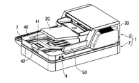
- FIG. 1 is a perspective view of an upper part of an image forming apparatus 1 including a sheet conveying device 3 according to the first embodiment of the present invention as viewed from the front
- FIG. 1B is an upper view of the image forming apparatus 1 as viewed from the rear. It is a perspective view.
- the image forming apparatus 1 shown in FIG. 1A is, for example, a copying machine, a fax machine, a scanner, a printer, or a multifunction machine.
- the image forming apparatus 1 forms an image on a sheet such as a copy sheet.
- the image forming apparatus 1 includes an image forming apparatus main body 2 and a sheet conveying apparatus 3 mounted on the image forming apparatus main body 2.
- the sheet conveying device 3 conveys a sheet on which a read image is recorded (hereinafter referred to as “original”).
- the sheet conveying device 3 is movably attached to the image forming apparatus main body 2.
- the sheet conveying apparatus 3 includes a conveying unit 30 that conveys a document, and a stacking unit 40 on which the document discharged from the conveying unit 30 is stacked.
- the sheet conveying device 3 has a protrusion 50.
- the protrusion 50 regulates the movement of the document stacked on the stacking unit 40 when the sheet conveying device 3 moves.
- the sheet conveying device 3 is rotatably attached to the image forming apparatus main body 2 via a pair of hinges 4 (only one is shown).
- the sheet conveying device 3 further includes a document table 20.
- the document table 20 protrudes obliquely upward from the entrance of the conveyance unit 30. A plurality of documents can be stacked on the document table 20.
- the transport unit 30 includes a transport roller, a discharge roller, and the like, although not shown.
- the conveyance unit 30 conveys the originals stacked on the original table 20 one by one along a conveyance path P indicated by a broken line in FIG. 1A.
- the loading unit 40 includes a tray 41 and a stopper 42.
- the document is discharged onto the tray 41 and stacked.
- the stopper 42 stops the document discharged on the tray 41.
- the stopper 42 is attached to the tray 41 so as to be slidable in the document discharge direction. Therefore, the position of the stopper 42 can be adjusted according to the size of the document.
- FIG. 2 is a perspective view showing a state where the sheet conveying device 3 is moved upward.
- the sheet conveying device 3 further includes a document presser 70.
- the document presser 70 presses the document placed on the image forming apparatus main body 2 so as not to move.
- the image forming apparatus main body 2 includes an image reading unit 5, a contact glass 6, a scanner (not shown), a paper feeding unit (not shown), an image forming unit (not shown), and a fixing unit (see FIG. (Not shown), a transport mechanism (not shown), and an operation display unit 7 are further provided.
- the image reading unit 5 reads a read image of a document conveyed by the sheet conveying device 3.
- a document that cannot be conveyed by the sheet conveying device 3 is placed on the contact glass 6.
- the document that cannot be transported by the sheet transport device 3 is, for example, a book-shaped document.
- the scanner reads an image of a document placed on the contact glass 6.
- the sheet feeding unit supplies a sheet such as a copy sheet to the image forming unit.
- the image forming unit forms a toner image on the sheet by an electrophotographic method based on the image read by the image reading unit 5 or the scanner.
- the fixing unit fixes the toner image on the sheet.
- the transport mechanism discharges the sheet on which the image is formed to a predetermined location.
- the operation display unit 7 includes a display 71 and an operation button group 72.
- the display 71 is constituted by a liquid crystal panel or the like.
- the display 71 displays various information.
- the operation button group 72 is used for the user to input
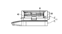
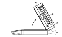
- FIG. 3A and 3B are side views of the upper part of the image forming apparatus 1.
- FIG. 3A shows a state in which the sheet conveying apparatus 3 is in contact with the upper surface of the image forming apparatus main body 2
- FIG. 3B shows a state in which the sheet conveying apparatus 3 is separated from the upper surface of the image forming apparatus main body 2.
- the sheet conveying device 3 rotates upward from the state shown in FIG. 3A with the pair of hinges 4 (see FIG. 1B) as fulcrums
- the document M stacked on the stacking unit 40 may fall from the sheet conveying device 3. .
- the document M is brought into contact with the protrusion 50 and the movement of the document M is restricted. Therefore, the document M can be prevented from dropping from the sheet conveying device 3.
- FIG. 4 is a plan view of the image forming apparatus 1.
- 5 is a cross-sectional view taken along the line VV in FIG. 4, and
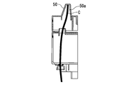
- FIG. 6 is a cross-sectional view taken along the line VI-VI in FIG.
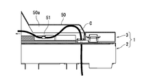
- the protrusion 50 is hollow.
- the protrusion 50 is formed so as to accommodate an electric wire C that electrically connects the sheet conveying apparatus 3 and the image forming apparatus main body 2.
- the internal space 50a of the protrusion 50 is formed so as to taper upward. Therefore, the protrusion 50 restricts the movement of the electric wire C in the radial direction. Therefore, since the change of the position of the electric wire C accompanying the movement of the sheet conveying apparatus 3 is suppressed, the generation of radio noise can be suppressed. Further, in the present embodiment, the appearance of the protrusion 50 is tapered. Therefore, since the protrusion 50 looks small, it is preferable in terms of appearance.
- an electric wire holder 51 is provided inside the protrusion 50.
- the electric wire holder 51 holds the electric wire C so as to be slidable in the length direction.
- the electric wire C is held by the electric wire holder 51 in a state where a part of the electric wire C is bent upward in an arc shape.
- the electric wire holder 51 can allow the electric wire C to slide along with the movement of the sheet conveying device 3. With this configuration, it is possible to suppress a great stress from being applied to the electric wire C. Since the change in the position of the electric wire C is suppressed by providing the electric wire holder 51, the generation of radio noise can be suppressed.
- the electric wire holder 51 may be omitted when the radio noise is within the allowable range even without the electric wire holder 51. Further, the electric wire holder 51 can be formed integrally with the housing of the sheet conveying apparatus 3. When the electric wire holder 51 is formed in the sheet conveying apparatus 3, the number of parts does not increase, and the structure of the sheet conveying apparatus 3 is not complicated.
- the bent portion of the electric wire C is accommodated in the protrusion 50, the bent portion of the electric wire C does not contact the wall of the room or other equipment. Therefore, damage and deterioration of the electric wire C can be suppressed. Further, when the sheet conveying apparatus 3 is moved with respect to the image forming apparatus main body 2, it is possible to suppress the electric wire C from being sandwiched between the sheet conveying apparatus 3 and the image forming apparatus main body 2.
- the protrusion 50 is hollow, and the electric wire C is accommodated in the internal space 50 a of the protrusion 50. Therefore, according to the present embodiment, even if the electric wire C is accommodated in the protrusion 50, the protrusion is also provided in the existing sheet conveying device, but the number of parts does not increase, and the structure Can be prevented from being damaged and deteriorated.
- FIG. 7 is a perspective view of the upper part of the image forming apparatus 11 including the sheet conveying apparatus 13 according to the second embodiment of the present invention.
- symbol is used for the site
- the sheet conveying device 13 is attached to the image forming apparatus main body 2 so as to be movable up and down.
- FIG. 8A and 8B are side views of the upper portion of the image forming apparatus 11 shown in FIG. Specifically, FIG. 8A shows a state where the sheet conveying device 13 is in contact with the upper surface of the image forming apparatus main body 2, and FIG. 8B shows a state where the sheet conveying device 13 is separated from the upper surface of the image forming apparatus main body 2.
- FIG. 8A the electric wire C accommodated in the protrusion 50 is bent similarly to the state shown in FIG. As the sheet conveying device 13 rises, the amount of deflection of the electric wire C housed inside the protrusion 50 gradually decreases.
- the sheet conveying device 13 has a pair of guide shafts 60 (only one is shown) protruding downward, and the sheet conveying device 13 is connected to the image forming apparatus main body 2 via the guide shafts 60. It is attached to the hoist freely.
- FIG. 9 is a plan view of the image forming apparatus 11.
- 10 is a cross-sectional view taken along the line XX of FIG. 9, and
- FIG. 11 is a cross-sectional view taken along the line XI-XI of FIG.
- the deflection amount of the electric wire C housed in the protrusion 50 decreases.
- the sheet conveying device 13 is lowered from the state shown in FIG. 8B, the amount of deflection of the electric wire C stored in the protrusion 50 increases.
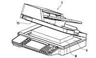
- FIG. 12 is a perspective view showing a state in which the document M is placed on the contact glass 6 of the image forming apparatus in which the sheet conveying device rotates
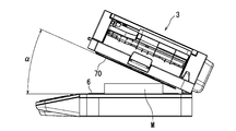
- FIG. 13 is a side view of the image forming apparatus shown in FIG. It is.
- the inclination angle ⁇ of the document holder 70 with respect to the contact glass 6 increases as the thickness of the document M placed on the contact glass 6 increases. That is, when the document retainer 70 of the sheet conveying device 3 is brought into contact with the document M, the inclination angle ⁇ of the document retainer 70 with respect to the contact glass 6 increases as the thickness of the document M placed on the contact glass 6 increases. As shown in FIG. As a result, the distance between the document holder 70 and the contact glass 6 is increased. For this reason, it becomes easy for external light to enter the scanner, and a portion of the copy paper other than the portion corresponding to the document is printed in black, so that useless toner is consumed.
- the movement distance of the electric wire C (see FIG. 6) is larger than that of the image forming apparatus in which the sheet conveying apparatus is rotated, so that the deflection amount of the electric wire C is large.
- the electric wire since the electric wire is exposed, the larger the amount of deflection of the electric wire, the easier it is for the electric wire to come into contact with the wall of the room or other equipment and to be damaged or deteriorated.
- the electric wire C since the electric wire C is housed in the protrusion 50, damage and deterioration of the electric wire can be more reliably suppressed even in the image forming apparatus in which the sheet conveying device moves up and down.
- the present invention can also be applied to a sheet conveying apparatus that conveys a sheet other than a document.
- the present invention is also applied to a sheet conveying apparatus that conveys copy paper on which an image is formed by an image forming unit, and a sheet conveying apparatus that conveys a sheet that has been post-processed (for example, staple processing) by a post-processing unit. can do.
- the present invention is applied to an image forming apparatus including an electrophotographic image forming unit.
- the present invention can also be applied to an image forming apparatus including an image forming unit.
Landscapes
- Physics & Mathematics (AREA)
- General Physics & Mathematics (AREA)
- Engineering & Computer Science (AREA)
- Multimedia (AREA)
- Signal Processing (AREA)
- Electrophotography Configuration And Component (AREA)
Abstract
シート搬送装置(3)は、シートに画像を形成する画像形成装置本体(2)に移動可能に取り付けられる。シート搬送装置(3)は、搬送部(30)と、積載部(40)と、突起(50)とを有する。搬送部(30)はシートを搬送する。積載部(40)には、搬送部(30)から排出されるシートが積載される。突起(50)は、積載部(40)に積載されたシートの移動を規制する。突起(50)は中空状で、シート搬送装置(3)と画像形成装置本体(2)とを電気的に接続する電線(C)を収納する。
Description
本発明は、シート搬送装置及び画像形成装置に関する。
複写機、ファクス、スキャナー、プリンター、又は複合機のような画像形成装置には、シート搬送装置が搭載されている。画像形成装置は、画像読取部と画像形成部とを備える。画像読取部は、原稿に記録された読取画像を読み取る。画像形成部は、画像読取部が読み取った画像に基づいて、コピー用紙のようなシートに画像を形成する。シート搬送装置は、原稿を画像読取部に搬送するために用いられる。
シート搬送装置は、画像形成装置本体に対して移動可能に取り付けられる。シート搬送装置は、原稿を搬送する搬送部と、搬送部から排出される原稿が積載される積載部とを有する。シート搬送装置と画像形成装置本体とは電線によって電気的に接続されている。電線を介して、シート搬送装置の動作に必要な電力と信号とが画像形成装置本体からシート搬送装置に供給される。
シート搬送装置が画像形成装置本体に対して移動することで、画像形成装置本体のコンタクトガラスが露出する。シート搬送装置で搬送できない原稿は、コンタクトガラス上に載置される。シート搬送装置で搬送できない原稿は、例えばブック状の原稿である。コンタクトガラス上に載置された原稿に記録された読取画像は、スキャナーによって読み取られる。シート搬送装置には、原稿の移動を規制する突起が設けられている。突起は、シート搬送装置が画像形成装置本体に対して移動する際に、シート搬送装置に積載された原稿が落下することを抑制する。
また、コンタクトガラス上に載置される原稿の厚みによっては、シート搬送装置がコンタクトガラスから離間する場合がある。このため、シート搬送装置と画像形成装置本体とを接続する電線にストレスがかからないように、電線にたわみを持たせている。しかし、電線のたわんだ部分が露出していると、そのたわんだ部分が部屋の壁や他の機器に接触して電線が損傷、劣化する虞がある。そこで、特許文献1に開示の画像形成装置では、画像形成装置本体に凹部が設けられている。凹部の内部には、フックが設けられている。電線がフックに係止され、凹部の内部に収納される。
しかしながら、特許文献1に開示の技術では、画像形成装置本体の構造が複雑化し、コスト高になるという問題がある。
本発明は、上記課題に鑑みて創案されたものであり、その目的は、構造を複雑にすることなく、シート搬送装置と画像形成装置本体とを電気的に接続する電線の損傷、劣化を抑制できるシート搬送装置及び画像形成装置を提供することにある。
本発明による第1の態様は、シートに画像を形成する画像形成装置の本体に移動可能に取り付けられるシート搬送装置である。当該シート搬送装置は、搬送部と、積載部と、突起とを有する。前記搬送部は、シートを搬送する。前記積載部には、前記搬送部から排出されるシートが積載される。前記突起は、前記積載部に積載されたシートの移動を規制する。前記突起は中空状で、前記画像形成装置の本体と当該シート搬送装置とを電気的に接続するための電線を収納するように形成される。
本発明による第2の態様は、画像形成装置である。当該画像形成装置は、第1の態様に係るシート搬送装置と、前記画像形成装置の本体とを備える。
本発明によれば、構造を複雑にすることなく、シート搬送装置と画像形成装置本体とを電気的に接続する電線の損傷、劣化を抑制できる。
以下、図面を参照して本発明による実施形態を説明する。図1は、本発明の第1実施形態に係るシート搬送装置3を備える画像形成装置1の上部を前方から見た斜視図であり、図1Bは、画像形成装置1の上部を後方から見た斜視図である。
図1Aに示す画像形成装置1は、例えば、複写機、ファクス、スキャナー、プリンター、又は複合機である。画像形成装置1は、コピー用紙のようなシートに画像を形成する。画像形成装置1は、画像形成装置本体2と、画像形成装置本体2に搭載されたシート搬送装置3とを備える。シート搬送装置3は、読取画像が記録されたシート(以下「原稿」と称する。)を搬送する。
シート搬送装置3は、画像形成装置本体2に移動可能に取り付けられている。シート搬送装置3は、原稿を搬送する搬送部30と、搬送部30から排出される原稿が積載される積載部40とを有する。図1Bに示すように、シート搬送装置3は突起50を有する。突起50は、シート搬送装置3が移動する際に、積載部40に積載された原稿の移動を規制する。
シート搬送装置3は、一対のヒンジ4(一方のみ図示)を介して、画像形成装置本体2に対して回動可能に取り付けられている。シート搬送装置3は、原稿テーブル20をさらに備える。原稿テーブル20は、搬送部30の入口から斜め上方に向けて突出している。原稿テーブル20には、複数枚の原稿が積載可能である。
搬送部30は、図示しないが、搬送ローラーや排出ローラー等を有する。搬送部30は、原稿テーブル20上に積載された原稿を図1Aの破線で示す搬送経路Pに沿って1枚ずつ搬送する。
積載部40は、トレー41とストッパー42とを有する。原稿はトレー41上に排出されて積載される。ストッパー42は、トレー41上に排出される原稿を停止させる。ストッパー42は、トレー41に対して原稿の排出方向に摺動可能に取り付けられている。したがって、原稿のサイズに合わせたストッパー42の位置の調節が可能となる。
図2は、シート搬送装置3を上方に移動させた状態を示す斜視図である。図2に示されるように、シート搬送装置3は、原稿押さえ70をさらに備える。原稿押さえ70は、画像形成装置本体2上に載置された原稿を移動しないように押さえる。
画像形成装置本体2は、画像読取部5と、コンタクトガラス6と、スキャナー(図示せず)と、給紙部(図示せず)と、画像形成部(図示せず)と、定着部(図示せず)と、搬送機構(図示せず)と、操作表示部7とをさらに備える。
画像読取部5は、シート搬送装置3によって搬送される原稿の読取画像を読み取る。コンタクトガラス6には、例えば、シート搬送装置3で搬送できない原稿が載置される。シート搬送装置3で搬送できない原稿は、例えばブック状の原稿である。スキャナーは、コンタクトガラス6上に載置された原稿の画像を読み取る。給紙部は、コピー用紙のようなシートを画像形成部に供給する。画像形成部は、画像読取部5又はスキャナーが読み取った画像に基づき、電子写真方式によって、シートにトナー画像を形成する。定着部は、トナー画像をシートに定着させる。搬送機構は、画像が形成されたシートを所定の箇所に排出する。操作表示部7は、表示器71と、操作ボタン群72とを含む。表示器71は液晶パネル等によって構成される。表示器71は、各種の情報を表示する。操作ボタン群72は、ユーザーが各種の情報を入力するために用いられる。
図3A及び図3Bは、画像形成装置1の上部の側面図である。詳しくは、図3Aは、シート搬送装置3が画像形成装置本体2の上面に当接した状態を示し、図3Bは、シート搬送装置3が画像形成装置本体2の上面から離間した状態を示す。図3Aに示す状態からシート搬送装置3が一対のヒンジ4(図1B参照)を支点として、上方に回動すると、積載部40に積載された原稿Mがシート搬送装置3から落下する恐れがある。しかし、本実施形態によれば、図3Bに示すように、原稿Mが突起50に当接して原稿Mの移動が規制される。よって原稿Mのシート搬送装置3からの落下を防止することができる。
図4は、画像形成装置1の平面図である。図5は、図4のV-V線断面図であり、図6は、図4のVI-VI線断面図である。図5に示すように、突起50は中空状である。突起50は、シート搬送装置3と画像形成装置本体2とを電気的に接続する電線Cを収納するように形成されている。
突起50の内部空間50aは、上方に向けて先細りとなるように形成されている。よって、突起50は、電線Cの径方向の移動を規制する。したがって、シート搬送装置3の移動に伴う電線Cの位置の変化が抑制されるため、電波ノイズの発生を抑制することができる。また、本実施形態では、突起50の外観が先細りである。したがって突起50が小さく見えるため、外観上も好ましい。
図6に示すように、突起50の内部には電線保持具51が設けられている。電線保持具51は電線Cを長さ方向に摺動可能に保持する。電線Cの一部が上方に円弧状にたわんだ状態で電線Cが電線保持具51に保持されている。電線保持具51は、シート搬送装置3の移動に伴う電線Cの摺動を許容することができる。この構成により、電線Cに大きなストレスがかかることを抑制することができる。電線保持具51を設けることで、電線Cの位置の変化が抑制されるため、電波ノイズの発生を抑制することができる。なお、電線保持具51が無くても電波ノイズが許容範囲の場合には、電線保持具51を省略してもよい。また、電線保持具51はシート搬送装置3の筐体に一体的に形成可能である。電線保持具51がシート搬送装置3に形成された場合、部品点数が増加しないため、シート搬送装置3の構造が複雑化しない。
シート搬送装置3では、突起50に電線Cのたわんだ部分が収納されるため、電線Cのたわんだ部分が部屋の壁や他の機器に接触することがない。したがって、電線Cの損傷、劣化を抑制できる。また、シート搬送装置3を画像形成装置本体2に対して移動する際に、電線Cがシート搬送装置3と画像形成装置本体2との間に挟み込まれることを抑制できる。
なお、本実施形態では、突起50は中空となっており、突起50の内部空間50aに電線Cが収容される。従って、本実施形態によれば、突起50に電線Cを収納するようにしても、突起は、既存のシート搬送装置にも設けられているが、部品点数が増加することはなく、また、構造を複雑にすることなく、電線Cの損傷、劣化を抑制できる。
図7は、本発明の第2実施形態に係るシート搬送装置13を備える画像形成装置11の上部の斜視図である。本実施形態において、第1実施形態と対応する部位には同一の符号を使用し、重複する説明を省略する。本実施形態では、シート搬送装置13が、画像形成装置本体2に対して昇降可能に取り付けられている。
図8A及び図8Bは、図7に示される画像形成装置11の上部の側面図である。詳しくは、図8Aは、シート搬送装置13が画像形成装置本体2の上面に当接した状態を示し、図8Bは、シート搬送装置13が画像形成装置本体2の上面から離間した状態を示す。図8Aに示される状態のとき、突起50の内部に収納された電線Cには、図6に示される状態と同様にたわみが生じている。シート搬送装置13が上昇するにつれて、突起50の内部に収納された電線Cのたわみ量が漸減する。
図8Bに示すように、シート搬送装置13は、下方に突出する一対のガイド軸60(一方のみ図示)を有しており、当該ガイド軸60を介してシート搬送装置13が画像形成装置本体2に昇降自在に取り付けられている。
図9は、画像形成装置11の平面図である。図10は、図9のX-X線断面図であり、図11は、図9のXI-XI線断面図である。図10及び図11に示すように、図8Aに示す状態からシート搬送装置13が上昇することによって、突起50の内部に収納されている電線Cのたわみ量は、減少する。一方、図8Bに示す状態からシート搬送装置13が下降すると、突起50の内部に収納されている電線Cのたわみ量が増加する。
次に、図12及び図13を参照して、シート搬送装置が昇降する画像形成装置に本発明を適用した場合の有用性について説明する。図12は、シート搬送装置が回動する画像形成装置のコンタクトガラス6上に原稿Mが載置された状態を示す斜視図であり、図13は、図12に示される画像形成装置の側面図である。
図12及び図13に示される画像形成装置では、コンタクトガラス6上に載置される原稿Mの厚みが大きい程、コンタクトガラス6に対する原稿押さえ70の傾斜角度αが大きくなる。即ち、シート搬送装置3の原稿押さえ70が原稿Mに当接させられた場合、コンタクトガラス6上に載置される原稿Mの厚みが大きい程コンタクトガラス6に対する原稿押さえ70の傾斜角度αが図13に示すように大きくなる。その結果、原稿押さえ70とコンタクトガラス6との距離が大きくなる。このため、スキャナーに外光が入射しやすくなり、コピー用紙のうち、原稿に対応する部分以外の部分が黒く印刷されるため、無駄なトナーが消費されてしまう。
一方、シート搬送装置が昇降する画像形成装置では、図8Bに示すように、コンタクトガラス6上に載置された原稿Mの厚みが大きくても、図12及び図13に示される画像形成装置と比べて、原稿押さえ70とコンタクトガラス6との距離を小さくできる。よって、スキャナーに外光が入射しにくい。したがって、無駄なトナーの消費を抑制することができる。
また、シート搬送装置3が昇降する画像形成装置では、シート搬送装置が回動する画像形成装置と比べて、電線C(図6参照)の移動距離が大きいため、電線Cのたわみ量が大きい。一般的な画像形成装置では、電線が露出しているため、電線のたわみ量が大きくなるほど、電線が部屋の壁や他の機器に接触して損傷、劣化しやすくなる。本発明では、電線Cが突起50内に収納されているため、シート搬送装置が昇降する画像形成装置であっても、電線の損傷、劣化をより確実に抑制することができる。
以上、図面(図1~図13)を参照しながら本発明の実施形態について説明した。但し、本発明は上記の実施形態に限られるものではなく、その要旨を逸脱しない範囲で種々の態様において実施することが可能である。なお、図面を理解しやすくするために、それぞれの各構成要素の厚み、長さ、個数等は、図面作成の都合上から、実際とは異なる。また、上記の実施形態で示す各構成要素の形状、寸法等は一例であって、特に限定されるものではなく、本発明の効果から実質的に逸脱しない範囲で種々の変更が可能である。
例えば、本実施形態では、シート搬送装置が原稿を搬送する装置である場合について説明したが、本発明は、原稿以外のシートを搬送するシート搬送装置にも適用可能である。例えば、画像形成部で画像が形成されたコピー用紙を搬送するシート搬送装置や、後処理部で後処理(例えば、ステープル処理)が行われたシートを搬送するシート搬送装置にも本発明を適用することができる。
また、本実施形態では、電子写真方式の画像形成部を備えた画像形成装置に本発明を適用した場合について説明したが、本発明は、電子写真方式以外の画像形成部(例えば、インクジェット方式の画像形成部)を備えた画像形成装置に適用することもできる。
Claims (9)
- シートに画像を形成する画像形成装置の本体に移動可能に取り付けられるシート搬送装置であって、
シートを搬送する搬送部と、
前記搬送部から排出されたシートが積載される積載部と、
前記積載部に積載されたシートの移動を規制する突起と
を有し、
前記突起は中空状で、前記画像形成装置の本体と当該シート搬送装置とを電気的に接続するための電線を収納するように形成された、シート搬送装置。
- 前記突起の内部空間は、前記電線の径方向の移動を規制するように、上方に向けて先細りとなるように形成された、請求項1に記載のシート搬送装置。
- 前記突起の内部に設けられ、前記電線を長さ方向に摺動可能に保持する電線保持具をさらに備える、請求項1に記載のシート搬送装置。
- 前記画像形成装置の本体に対して回動可能に取り付けられる、請求項1に記載のシート搬送装置。
- 前記画像形成装置の本体に対して昇降可能に取り付けられる、請求項1に記載のシート搬送装置。
- 読取画像が記録された原稿を搬送する、請求項1に記載のシート搬送装置。
- 前記突起の内部に設けられ、前記電線を長さ方向に摺動可能に保持する電線保持具をさらに備え、
前記突起の内部空間は、前記電線の径方向の移動を規制するように、上方に向けて先細りとなるように形成され、
前記画像形成装置の本体に対して回動可能に取り付けられる、請求項1に記載のシート搬送装置。
- 前記突起の内部に設けられ、前記電線を長さ方向に摺動可能に保持する電線保持具をさらに備え、
前記突起の内部空間は、前記電線の径方向の移動を規制するように、上方に向けて先細りとなるように形成され、
前記画像形成装置の本体に対して昇降可能に取り付けられる、請求項1に記載のシート搬送装置。
- 請求項1に記載のシート搬送装置と、
前記画像形成装置の本体と
を備える、画像形成装置。
Applications Claiming Priority (2)
| Application Number | Priority Date | Filing Date | Title |
|---|---|---|---|
| JP2014066313 | 2014-03-27 | ||
| JP2014-066313 | 2014-03-27 |
Publications (1)
| Publication Number | Publication Date |
|---|---|
| WO2015146325A1 true WO2015146325A1 (ja) | 2015-10-01 |
Family
ID=54194864
Family Applications (1)
| Application Number | Title | Priority Date | Filing Date |
|---|---|---|---|
| PCT/JP2015/053624 Ceased WO2015146325A1 (ja) | 2014-03-27 | 2015-02-10 | シート搬送装置及び画像形成装置 |
Country Status (1)
| Country | Link |
|---|---|
| WO (1) | WO2015146325A1 (ja) |
Citations (3)
| Publication number | Priority date | Publication date | Assignee | Title |
|---|---|---|---|---|
| JP2008268712A (ja) * | 2007-04-24 | 2008-11-06 | Ricoh Elemex Corp | 画像形成装置 |
| JP2008276058A (ja) * | 2007-05-02 | 2008-11-13 | Ricoh Elemex Corp | 画像形成装置 |
| JP2011211595A (ja) * | 2010-03-30 | 2011-10-20 | Brother Industries Ltd | 画像読取装置 |
-
2015
- 2015-02-10 WO PCT/JP2015/053624 patent/WO2015146325A1/ja not_active Ceased
Patent Citations (3)
| Publication number | Priority date | Publication date | Assignee | Title |
|---|---|---|---|---|
| JP2008268712A (ja) * | 2007-04-24 | 2008-11-06 | Ricoh Elemex Corp | 画像形成装置 |
| JP2008276058A (ja) * | 2007-05-02 | 2008-11-13 | Ricoh Elemex Corp | 画像形成装置 |
| JP2011211595A (ja) * | 2010-03-30 | 2011-10-20 | Brother Industries Ltd | 画像読取装置 |
Similar Documents
| Publication | Publication Date | Title |
|---|---|---|
| JP4947178B2 (ja) | 画像読取装置 | |
| JP5003781B2 (ja) | 複合機 | |
| CN101534366B (zh) | 纸片处理装置 | |
| JP4947177B2 (ja) | 画像読取装置 | |
| US9247087B2 (en) | Electronic apparatus including main unit and open/close unit movable in up and down direction and openable/closeable in rotating direction relative to main unit | |
| CN104076639B (zh) | 图像形成装置 | |
| JP6082102B2 (ja) | 画像形成装置及びスキャナー装置 | |
| JP4577202B2 (ja) | 読取機能付き画像形成装置 | |
| JP2012176853A (ja) | 給紙装置 | |
| JP5934659B2 (ja) | 画像形成装置 | |
| JP5899157B2 (ja) | 画像形成装置 | |
| CN110651462B (zh) | 图像形成装置 | |
| US9019582B2 (en) | Image reading apparatus | |
| JP5026034B2 (ja) | 給紙装置および画像読取装置 | |
| CN103309193B (zh) | 图像形成装置 | |
| JP2006343613A (ja) | 画像形成装置 | |
| JP4503026B2 (ja) | ファクシミリ装置およびその給排紙機構 | |
| CN103129988B (zh) | 止挡元件、馈纸装置及事务机 | |
| JP2006126405A (ja) | 画像処理装置 | |
| JP4251293B2 (ja) | 画像読取形成装置 | |
| CN108462804A (zh) | 图像读取装置、图像形成装置、限位构件 | |
| JP2025107997A (ja) | 画像形成装置および画像読取装置 | |
| CN107111270A (zh) | 图像形成装置 | |
| JP2017019642A (ja) | 用紙搬送装置及び画像形成装置 | |
| JP2008160714A (ja) | スキャナ装置及びそれを用いた画像形成装置 |
Legal Events
| Date | Code | Title | Description |
|---|---|---|---|
| 121 | Ep: the epo has been informed by wipo that ep was designated in this application |
Ref document number: 15769443 Country of ref document: EP Kind code of ref document: A1 |
|
| NENP | Non-entry into the national phase |
Ref country code: DE |
|
| NENP | Non-entry into the national phase |
Ref country code: JP |
|
| 122 | Ep: pct application non-entry in european phase |
Ref document number: 15769443 Country of ref document: EP Kind code of ref document: A1 |