WO2015146306A1 - レーザ装置及びそれを備えた光音響計測装置 - Google Patents
レーザ装置及びそれを備えた光音響計測装置 Download PDFInfo
- Publication number
- WO2015146306A1 WO2015146306A1 PCT/JP2015/053270 JP2015053270W WO2015146306A1 WO 2015146306 A1 WO2015146306 A1 WO 2015146306A1 JP 2015053270 W JP2015053270 W JP 2015053270W WO 2015146306 A1 WO2015146306 A1 WO 2015146306A1
- Authority
- WO
- WIPO (PCT)
- Prior art keywords
- wavelength
- light
- resonator
- laser
- delay time
- Prior art date
- Legal status (The legal status is an assumption and is not a legal conclusion. Google has not performed a legal analysis and makes no representation as to the accuracy of the status listed.)
- Ceased
Links
Images


Classifications
-
- H—ELECTRICITY
- H01—ELECTRIC ELEMENTS
- H01S—DEVICES USING THE PROCESS OF LIGHT AMPLIFICATION BY STIMULATED EMISSION OF RADIATION [LASER] TO AMPLIFY OR GENERATE LIGHT; DEVICES USING STIMULATED EMISSION OF ELECTROMAGNETIC RADIATION IN WAVE RANGES OTHER THAN OPTICAL
- H01S3/00—Lasers, i.e. devices using stimulated emission of electromagnetic radiation in the infrared, visible or ultraviolet wave range
- H01S3/10—Controlling the intensity, frequency, phase, polarisation or direction of the emitted radiation, e.g. switching, gating, modulating or demodulating
- H01S3/11—Mode locking; Q-switching; Other giant-pulse techniques, e.g. cavity dumping
- H01S3/1123—Q-switching
- H01S3/127—Plural Q-switches
-
- A—HUMAN NECESSITIES
- A61—MEDICAL OR VETERINARY SCIENCE; HYGIENE
- A61B—DIAGNOSIS; SURGERY; IDENTIFICATION
- A61B5/00—Measuring for diagnostic purposes; Identification of persons
- A61B5/0093—Detecting, measuring or recording by applying one single type of energy and measuring its conversion into another type of energy
- A61B5/0095—Detecting, measuring or recording by applying one single type of energy and measuring its conversion into another type of energy by applying light and detecting acoustic waves, i.e. photoacoustic measurements
-
- H—ELECTRICITY
- H01—ELECTRIC ELEMENTS
- H01S—DEVICES USING THE PROCESS OF LIGHT AMPLIFICATION BY STIMULATED EMISSION OF RADIATION [LASER] TO AMPLIFY OR GENERATE LIGHT; DEVICES USING STIMULATED EMISSION OF ELECTROMAGNETIC RADIATION IN WAVE RANGES OTHER THAN OPTICAL
- H01S3/00—Lasers, i.e. devices using stimulated emission of electromagnetic radiation in the infrared, visible or ultraviolet wave range
- H01S3/05—Construction or shape of optical resonators; Accommodation of active medium therein; Shape of active medium
- H01S3/08—Construction or shape of optical resonators or components thereof
- H01S3/08086—Multiple-wavelength emission
- H01S3/0809—Two-wavelenghth emission
-
- H—ELECTRICITY
- H01—ELECTRIC ELEMENTS
- H01S—DEVICES USING THE PROCESS OF LIGHT AMPLIFICATION BY STIMULATED EMISSION OF RADIATION [LASER] TO AMPLIFY OR GENERATE LIGHT; DEVICES USING STIMULATED EMISSION OF ELECTROMAGNETIC RADIATION IN WAVE RANGES OTHER THAN OPTICAL
- H01S3/00—Lasers, i.e. devices using stimulated emission of electromagnetic radiation in the infrared, visible or ultraviolet wave range
- H01S3/05—Construction or shape of optical resonators; Accommodation of active medium therein; Shape of active medium
- H01S3/08—Construction or shape of optical resonators or components thereof
- H01S3/081—Construction or shape of optical resonators or components thereof comprising three or more reflectors
- H01S3/082—Construction or shape of optical resonators or components thereof comprising three or more reflectors defining a plurality of resonators, e.g. for mode selection or suppression
-
- H—ELECTRICITY
- H01—ELECTRIC ELEMENTS
- H01S—DEVICES USING THE PROCESS OF LIGHT AMPLIFICATION BY STIMULATED EMISSION OF RADIATION [LASER] TO AMPLIFY OR GENERATE LIGHT; DEVICES USING STIMULATED EMISSION OF ELECTROMAGNETIC RADIATION IN WAVE RANGES OTHER THAN OPTICAL
- H01S3/00—Lasers, i.e. devices using stimulated emission of electromagnetic radiation in the infrared, visible or ultraviolet wave range
- H01S3/09—Processes or apparatus for excitation, e.g. pumping
- H01S3/091—Processes or apparatus for excitation, e.g. pumping using optical pumping
- H01S3/0915—Processes or apparatus for excitation, e.g. pumping using optical pumping by incoherent light
- H01S3/092—Processes or apparatus for excitation, e.g. pumping using optical pumping by incoherent light of flash lamp
-
- H—ELECTRICITY
- H01—ELECTRIC ELEMENTS
- H01S—DEVICES USING THE PROCESS OF LIGHT AMPLIFICATION BY STIMULATED EMISSION OF RADIATION [LASER] TO AMPLIFY OR GENERATE LIGHT; DEVICES USING STIMULATED EMISSION OF ELECTROMAGNETIC RADIATION IN WAVE RANGES OTHER THAN OPTICAL
- H01S3/00—Lasers, i.e. devices using stimulated emission of electromagnetic radiation in the infrared, visible or ultraviolet wave range
- H01S3/14—Lasers, i.e. devices using stimulated emission of electromagnetic radiation in the infrared, visible or ultraviolet wave range characterised by the material used as the active medium
- H01S3/16—Solid materials
- H01S3/163—Solid materials characterised by a crystal matrix
- H01S3/1631—Solid materials characterised by a crystal matrix aluminate
- H01S3/1633—BeAl2O4, i.e. Chrysoberyl
-
- H—ELECTRICITY
- H01—ELECTRIC ELEMENTS
- H01S—DEVICES USING THE PROCESS OF LIGHT AMPLIFICATION BY STIMULATED EMISSION OF RADIATION [LASER] TO AMPLIFY OR GENERATE LIGHT; DEVICES USING STIMULATED EMISSION OF ELECTROMAGNETIC RADIATION IN WAVE RANGES OTHER THAN OPTICAL
- H01S3/00—Lasers, i.e. devices using stimulated emission of electromagnetic radiation in the infrared, visible or ultraviolet wave range
- H01S3/10—Controlling the intensity, frequency, phase, polarisation or direction of the emitted radiation, e.g. switching, gating, modulating or demodulating
- H01S3/106—Controlling the intensity, frequency, phase, polarisation or direction of the emitted radiation, e.g. switching, gating, modulating or demodulating by controlling devices placed within the cavity
Definitions
- the present invention relates to a laser device, and more particularly to a laser device capable of emitting light of a first wavelength and light of a second wavelength.
- the present invention also relates to a photoacoustic measurement device provided with such a laser device.
- a photoacoustic image generation apparatus that images a living body using a photoacoustic effect is known.
- a living body is irradiated with pulsed light such as pulsed laser light.
- pulsed light such as pulsed laser light.
- the living tissue that has absorbed the energy of the pulsed light undergoes volume expansion due to heat, and an acoustic wave is generated.
- This acoustic wave is detected by an ultrasonic probe or the like, and the inside of the living body can be imaged based on the detected signal (photoacoustic signal).
- an acoustic wave is generated in a specific light absorber, so that a specific tissue in a living body, such as a blood vessel, can be imaged.
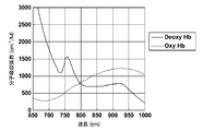
- FIG. 14 shows oxygenated hemoglobin (oxyhemoglobin combined with oxygen: oxy-Hb) abundant in human arteries and deoxygenated hemoglobin (hemoglobin deoxy-Hb not bound to oxygen) abundantly contained in veins.
- the molecular absorption coefficient for each light wavelength is shown.
- the light absorption characteristic of the artery corresponds to that of oxygenated hemoglobin
- the light absorption characteristic of the vein corresponds to that of deoxygenated hemoglobin.
- a photoacoustic image generation method is known in which a difference in optical absorptance according to the wavelength is used to irradiate a blood vessel portion with light of two different wavelengths, and an artery and a vein are distinguished and imaged. (For example, refer to Patent Document 2).
- Patent Documents 3 and 4 describe a variable wavelength laser device capable of emitting light of the two types of wavelengths as described above. These laser devices are alexandrite laser light sources using a flash lamp as an excitation source, and can oscillate at wavelengths of 755 nm and 800 nm.
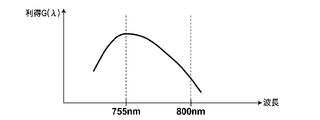
- FIG. 15 is a graph showing the relationship between the oscillation wavelength and luminous efficiency (gain) when alexandrite is used as the laser medium. As can be seen from this graph, for example, the luminous efficiency of alexandrite becomes maximum near the wavelength of 755 nm, and decreases as the wavelength becomes longer in the wavelength range exceeding the wavelength of 755 nm.
- a laser having two oscillation wavelengths having different emission efficiencies for example, a wavelength having a lower emission efficiency is referred to as a “first wavelength” and a wavelength having a higher emission efficiency is referred to as a “second wavelength”).
- first wavelength a wavelength having a lower emission efficiency
- second wavelength a wavelength having a higher emission efficiency
- laser beams having different intensities are oscillated.
- the intensity of the light of the second wavelength may exceed the damage threshold of the apparatus.
- the oscillation wavelength is the second wavelength, it is sufficient if the excitation energy of the laser medium can be reduced in order to reduce the intensity of the light of the second wavelength. There is also a limit to the amount of decrease in excitation energy.
- the present invention has been made in view of the above demands, and in a laser apparatus using a laser medium having two oscillation wavelengths having different emission efficiencies, the intensity of light of each wavelength can be increased without increasing the number of parts of the apparatus. It is an object of the present invention to provide a laser device that can be controlled independently and a photoacoustic measurement device including the laser device.
- the laser device of the present invention is: A solid-state laser medium having an oscillation wavelength at a first wavelength and a second wavelength having higher emission efficiency than the first wavelength; An excitation unit for exciting the laser medium; A first resonator that oscillates light of a first wavelength and has a laser medium on an internal optical path; A second resonator that oscillates light of a second wavelength and has a common optical path that is a common optical path with the first resonator including the optical path in which the laser medium is disposed; A Q value changing unit that includes at least a Q value changing unit disposed on the common optical path, and that Q-oscillates light having the first wavelength or light having the second wavelength; and A control unit for controlling the excitation unit and the Q value changing unit, The control unit When the oscillation wavelength is the first wavelength, the Q value changing unit is controlled when the first delay time has elapsed since the excitation of the laser medium is started, so that the light of the first wavelength is Q-switched, When the oscillation wavelength is the first wavelength,
- the first delay time and the second delay time are set to values at which the intensity of the first wavelength light and the intensity of the second wavelength light are equal to each other. It is preferable.
- the first delay time is set to a value at which the intensity of light of the first wavelength is the maximum possible intensity.
- the control unit changes the set value of the first delay time or the second delay time in accordance with the amount of excitation energy given to the laser medium by the excitation unit.
- the excitation unit includes a flash lamp as a light source, and the control unit changes the set value of the first delay time or the second delay time according to the charging voltage of the flash lamp.
- the control unit has a first reference table in which the charging voltage and the set value of the first delay time or the second delay time are associated with each other, and the first reference table is based on the first reference table. A configuration for changing the set value of the delay time or the second delay time can be employed.
- the excitation unit includes an excitation light source
- the control unit changes the set value of the first delay time or the second delay time according to the use period of the excitation light source.
- the control unit has a second reference table in which the use period and the set value of the first delay time or the second delay time are associated with each other, and the first reference table is based on the second reference table. A configuration in which the set value of the delay time or the second delay time is changed can be employed.
- the first resonator includes a first mirror and a second mirror that are opposed to each other with the laser medium interposed therebetween, and the second resonator includes the first mirror
- the Q medium changing unit includes a laser medium and a third mirror that faces the first mirror across the second mirror
- the Q value changing unit includes a first Q value changing unit disposed on the common optical path, and a second mirror.
- a second Q value changing unit arranged between the third mirror and the third mirror.
- the control unit further includes the resonator length of the first resonator. It is preferable to change the set value of the first delay time according to the above, or change the set value of the second delay time according to the resonator length of the second resonator.
- the control unit includes a third reference table in which the resonator length of the first resonator and the set value of the first delay time are associated, and / or the resonator length of the second resonator and the first resonator length.
- the fourth reference table is associated with the set value of the second delay time, changes the set value of the first delay time based on the third reference table, and based on the fourth reference table It is preferable to change the set value of the second delay time.
- the control unit oscillates the driving states of the first Q value changing unit and the second Q value changing unit, and the Q values of the first resonator and the second resonator oscillate.
- a first driving state in which the Q value is lower than a threshold value a second driving state in which the Q values of the first and second resonators are higher than an oscillation threshold, and
- the first resonator is switched between a third driving state in which the Q value of the first resonator is in a high Q state and the Q value of the second resonator is in a low Q state.
- control unit sets the driving state of the first Q value changing unit and the second Q value changing unit to the first driving state when the laser medium is excited. Further, the control unit changes the driving state of the first Q value changing unit and the second Q value changing unit from the first driving state when the oscillation wavelength is the first wavelength after excitation of the laser medium. It is preferable to switch to the third driving state and switch from the first driving state to the second driving state when the oscillation wavelength is the second wavelength.
- the first Q value changing unit includes a first Q switch that changes the Q value of the first resonator according to the applied voltage
- the second Q value changing unit is A second Q switch that changes the Q value of the second resonator according to the applied voltage
- the control unit controls the first Q value changing unit and the second Q value by controlling the applied voltage. It is preferable to drive the part.
- the photoacoustic measuring device of the present invention includes the laser device described above, And a probe for detecting a photoacoustic wave generated in the subject using laser light emitted from the laser device.
- the photoacoustic measuring device of this invention is provided with the signal processing part which processes the signal of the photoacoustic wave detected using the probe.
- the signal processing unit includes an acoustic image generation unit that generates a photoacoustic image based on a photoacoustic wave signal. It is preferable to generate a reflected acoustic wave image based on the reflected acoustic wave signal transmitted.
- a laser apparatus and a photoacoustic measurement apparatus include a solid laser medium having an oscillation wavelength at a first wavelength and a second wavelength having higher emission efficiency than the first wavelength, an excitation unit, A resonator that oscillates light of a wavelength and has a laser medium on an internal optical path, and a resonator that oscillates light of a second wavelength and has an optical path on which the laser medium is disposed.
- a change unit that controls the excitation unit and the Q value change unit.
- the control unit controls the Q value changing unit when the first delay time has elapsed after the excitation of the laser medium, and switches the light of the first wavelength to the Q switch.
- the Q value is changed when the second delay time elapses when the intensity of light of the second wavelength becomes less than the maximum possible intensity after the excitation of the laser medium is started.
- the unit is controlled to cause the light of the second wavelength to oscillate Q-switch.
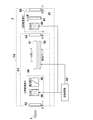
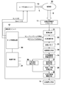
- FIG. 1 is a schematic diagram showing a configuration of a laser apparatus 1 according to the present embodiment.
- the laser device 1 includes a laser rod 51, a flash lamp (excitation lamp) 52, a first mirror 53, a second mirror 54, a third mirror 55, and a first Q value changing unit. 56, a second Q value changing unit 57 and a control circuit 62.
- the first Q value changing unit 56 and the second Q value changing unit 57 as a whole correspond to the Q value changing unit in the present invention.
- the laser device 1 emits laser light L having a plurality of wavelengths including a first wavelength and a second wavelength. For example, in this specification, it is assumed that the gain (luminous efficiency) at the second wavelength for laser oscillation is higher than the gain at the first wavelength.
- the laser rod 51 is a laser medium.
- the laser rod 51 has oscillation wavelengths at 800 nm and 755 nm.
- an alexandrite crystal can be used for the laser rod 51.
- the gain of laser light of alexandrite has a peak around the wavelength of 755 nm.
- the gain monotonously decreases as the wavelength becomes shorter in the wavelength range shorter than the wavelength of 755 nm. Further, the gain monotonously decreases as the wavelength becomes longer in the wavelength range longer than the wavelength of 755 nm.
- the gain of the alexandrite crystal at a wavelength of 800 nm is lower than the gain at a wavelength of 755 nm.
- the molecular absorption coefficient at a wavelength of 755 nm of oxygenated hemoglobin contained in a large amount in a human artery is lower than the molecular absorption coefficient at a wavelength of 800 nm.
- the molecular absorption coefficient at a wavelength of 755 nm of deoxygenated hemoglobin contained in a large amount in veins is higher than the molecular absorption coefficient at a wavelength of 800 nm.
- the photoacoustic signal obtained by irradiating light with a wavelength of 755 nm is relatively large or small with respect to the photoacoustic signal obtained by irradiating light with a wavelength of 800 nm.
- the photoacoustic signal from the artery and the photoacoustic signal from the vein can be discriminated.
- the oxygen saturation can be measured.
- any combination of two wavelengths may be used as long as there is a difference in the light absorption coefficient between the two selected wavelengths, and the above-described about 755 nm and about 800 nm.
- the combination is not limited.
- the two wavelengths selected are about 800 nm (exactly 798 nm) at which the light absorption coefficient is the same between oxygenated hemoglobin and deoxygenated hemoglobin, and the light of deoxygenated hemoglobin.
- a combination with a wavelength of about 755 nm (more precisely, 757 nm) at which the absorption coefficient becomes a maximum value is preferable.
- the first wavelength does not need to be exactly 798 nm.
- the second wavelength does not need to be exactly 757 nm.
- the second wavelength is in the range of 748 to 770 nm which is the half-value width of the peak near the maximum value (757 nm), there is no practical problem.
- the flash lamp 52 is an excitation light source as an excitation unit in the present invention, and irradiates the laser rod 51 with excitation light.
- the flash lamp 52 is driven intermittently.
- the flash lamp 52 is lit in conjunction with a flash lamp trigger transmitted from the control circuit 62.
- a light source other than the flash lamp 52 may be used as the excitation light source.
- the first mirror 53, the second mirror 54, and the third mirror 55 are arranged along the optical axis of the laser rod 51.
- the first mirror 53 and the second mirror 54 face each other with the laser rod 51 interposed therebetween.
- the third mirror 55 is disposed on the side opposite to the laser rod 51 when viewed from the second mirror 54, and faces the first mirror 53 with the laser rod 51 and the second mirror 54 interposed therebetween.
- the first mirror 53 is an output mirror of light having a wavelength of 800 nm and light having a wavelength of 755 nm.
- the reflectance of the first mirror 53 with respect to light with a wavelength of 800 nm is higher than the reflectance with respect to light with a wavelength of 755 nm.
- the reflectance of the first mirror 53 with respect to light with a wavelength of 800 nm is 80%
- the reflectance with respect to light with a wavelength of 755 nm is 70%.
- the second mirror 54 reflects light having a wavelength of 800 nm and transmits light having a wavelength of 755 nm.
- the reflectance of the second mirror 54 with respect to light with a wavelength of 800 nm is 99.8% or more, and the reflectance with respect to light with a wavelength of 755 nm is 0.5% or less.
- the third mirror 55 reflects light having a wavelength of 755 nm.
- the reflectance of the third mirror 55 with respect to light having a wavelength of 755 nm is, for example, 99.8% or more.
- the first mirror 53 and the second mirror 54 constitute a first resonator C1 that oscillates light having a wavelength of 800 nm.
- light having a wavelength of 755 nm emitted from the laser rod 51 passes through the second mirror 54 and is reflected by the third mirror 55, and reciprocates between the first mirror 53 and the third mirror 55.
- the first mirror 53 and the third mirror 55 constitute a second resonator C2 that oscillates light having a wavelength of 755 nm.
- the resonator length of the first resonator C1 is shorter than the resonator length of the second resonator C2.
- the optical path from the first mirror 53 to the second mirror 54 is an optical path common to the first resonator C1 and the second resonator C2, and the laser rod 51 is disposed on this common optical path. .
- the first Q value changing unit 56 is disposed on the common optical path of the first resonator C1 and the second resonator C2, and controls the Q values of the first resonator C1 and the second resonator C2. To do.
- the first Q value changing unit 56 is disposed, for example, between the first mirror 53 and the laser rod 51. Instead, the first Q value changing unit 56 may be disposed between the laser rod 51 and the second mirror 54.
- the first Q value changing unit 56 includes a first Q switch 58 and a polarizer 59.
- the first Q switch 58 changes the Q values of the first resonator C1 and the second resonator C2 according to the applied voltage.
- the first Q switch 58 can be an electro-optic element that changes the polarization state of the light passing therethrough according to the applied voltage.
- a Pockels cell is used for the first Q switch 58.
- the first Q switch 58 sets the first resonator C1 and the second resonator C2 to a low Q state when the applied voltage is the first voltage corresponding to the Q switch off.
- the low Q state refers to a state where the Q value of the resonator is lower than the laser oscillation threshold value.
- the first voltage is a voltage at which the first Q switch 58 functions as a quarter wave plate, for example.
- the first Q switch 58 sets the first resonator C1 and the second resonator C2 to a high Q state when the applied voltage is a second voltage corresponding to the Q switch on.
- the high Q state refers to a state where the Q value of the resonator is higher than the laser oscillation threshold value.
- the absolute value of the second voltage is smaller than the absolute value of the first voltage, and the voltage may be a positive voltage or a negative voltage.
- the second voltage is, for example, 0 V (no voltage applied), and the polarization state of the light transmitted through the first Q switch 58 does not change at this time. Since the voltage at which the Pockels cell works as a quarter wavelength plate varies depending on the wavelength, the second voltage corresponding to the Q switch-on differs between oscillation at a wavelength of 800 nm and oscillation at a wavelength of 755 nm.
- the voltage applied to the Pockels cell differs depending on whether the wavelength is 800 nm or 755 nm. For this reason, in the case of a configuration in which the applied voltage 0 V to the Pockels cell does not correspond to the Q switch on, the control circuit of the Q switch and the control method thereof are somewhat complicated. Therefore, it is preferable that the first Q value changing unit 56 has a configuration in which the applied voltage 0 V corresponds to the Q switch on.
- the polarizer 59 is disposed between the laser rod 51 and the first Q switch 58.
- the polarizer 59 transmits only linearly polarized light in a predetermined direction.
- a beam splitter that transmits linearly polarized light (for example, p-polarized light) in a predetermined direction and reflects a direction orthogonal to the predetermined direction (for example, s-polarized light) can be used.
- the polarizer 59 may be omitted if the light emitted from the laser rod 51 is p-polarized light, such as when an alexandrite crystal is used for the laser rod 51.
- the first Q switch 58 when a first voltage is applied to the first Q switch 58, the first Q switch 58 functions as a quarter wavelength plate. At this time, the p-polarized light incident on the first Q switch 58 from the polarizer 59 becomes circularly polarized light when passing through the first Q switch 58. Thereafter, the light is reflected by the first mirror 53 and enters the first Q switch 58 in the reverse direction. The circularly polarized light incident on the first Q switch 58 in the reverse direction becomes s-polarized light when passing through the first Q switch 58. Thereafter, the light is reflected by a polarizer 59 that reflects s-polarized light and is emitted out of the optical path of the resonator.
- the applied voltage to the first Q switch 58 is 0 V (second voltage)
- the p-polarized light incident on the first Q switch 58 from the polarizer 59 remains as the p-polarized light.
- the light passes through the switch 58 and is reflected by the first mirror 53.
- the p-polarized light reflected by the first mirror 53 passes through the first Q switch 58 as p-polarized light, passes through the polarizer 59 that transmits p-polarized light, and enters the laser rod 51.
- the second Q value changing unit 57 is disposed on the optical path of the second resonator C2 between the second mirror 54 and the third mirror 55, and controls the Q value of the second resonator C2. .
- the second Q value changing unit 57 includes a second Q switch 60 and a quarter wavelength plate 61.
- the second Q switch 60 changes the Q value of the second resonator C2 according to the applied voltage.
- the second Q switch 60 can be an electro-optic element that changes the polarization state of light passing therethrough according to the applied voltage.
- the quarter wavelength plate 61 is disposed between the second Q switch 60 and the third mirror 55.
- a Pockels cell is used for the second Q switch 60.
- the second Q switch 60 sets the second resonator C2 to a low Q state when the applied voltage is the third voltage corresponding to the Q switch off.
- the third voltage is, for example, 0 V (no voltage applied), and at this time, the polarization state of the light transmitted through the second Q switch 60 does not change.
- the second Q switch 60 sets the second resonator C2 to a high Q state when the applied voltage is a fourth voltage corresponding to the Q switch being turned on.
- the absolute value of the fourth voltage is larger than the absolute value of the third voltage, and the voltage may be a positive voltage or a negative voltage.
- the fourth voltage is a voltage at which the second Q switch 60 functions as a quarter wavelength plate, for example.
- the second mirror 54 reflects light having a wavelength of 800 nm and transmits light having a wavelength of 755 nm.
- the light traveling between the second mirror 54 and the third mirror 55 is light having a wavelength of 755 nm, and the light having a wavelength of 800 nm does not travel from the second mirror 54 to the third mirror 55 side.
- the second Q switch 60 functions as a quarter wavelength plate.
- the p-polarized light that has entered the second Q switch 60 through the second mirror 54 from the laser rod 51 side becomes circularly polarized light when passing through the second Q switch 60, and is further a quarter-wave plate.
- the light reflected by the third mirror 55 becomes circularly polarized when passing through the quarter-wave plate 61 in the reverse direction, and further becomes p-polarized when passing through the second Q switch 60, and the laser rod 51.
- the control circuit 62 corresponds to the control unit in the present invention, and drives the first Q value changing unit 56 and the second Q value changing unit 57.
- the control circuit 62 sets the driving states of the first resonator C1 and the second resonator C2 in the first driving state in which the Q values of the resonators are both low Q states lower than the oscillation threshold, A second drive state where both the Q values of the resonators are in a high Q state higher than the oscillation threshold, and the first resonator C1 is in a high Q state and the second resonator C2 is in a low Q state. Switch between the third driving states.
- the control circuit 62 drives the first Q value changing unit 56 by controlling the voltage applied to the first Q switch 58 and controls the second voltage by controlling the voltage applied to the second Q switch 60.
- the Q value changing unit 57 is driven.
- the control circuit 62 transmits a Q switch trigger to the first Q value changing unit and / or the second Q value changing unit, and oscillates the laser beam using the switching of the three driving states.
- the control circuit 62 also drives the flash lamp 52 by transmitting a flash lamp trigger instructing the lighting of the flash lamp 52.
- the first driving state the first voltage is applied to the first Q switch 58, and the first Q switch 58 functions as a quarter wavelength plate.
- the voltage applied to the second Q switch 60 is 0 V (third voltage), and the polarization state of the light passing through the second Q switch 60 does not change. Therefore, the light reflected by the first mirror 53 does not enter the laser rod 51 because the first Q switch 58 functions as a quarter wavelength plate. Further, since the polarization state of the light passing through the second Q switch 60 does not change, the light having a wavelength of 755 nm reflected by the third mirror 55 enters the laser rod 51 as s-polarized light.
- the first resonator C1 and the second resonator C2 are in a low Q state, and laser oscillation does not occur for both the wavelength 800 nm and the wavelength 755 nm.
- the first Q switch 58 is disposed on the common optical path, and the second resonator C2 can be brought into a low Q state by applying a first voltage to the first Q switch 58.
- the voltage applied to the second Q switch 60 is not particularly limited to the third voltage
- the fourth voltage is applied to the second Q switch 60
- the second voltage The Q switch 60 may be used as a quarter wavelength plate.
- the voltage applied to the first Q switch 58 is 0 V (second voltage), and the polarization state of the light passing through the first Q switch 58 does not change.
- the fourth voltage is applied to the second Q switch 60, and the second Q switch 60 functions as a quarter wavelength plate. Accordingly, since the polarization state of the light passing through the first Q switch 58 does not change, the light reflected by the first mirror 53 enters the laser rod 51 as p-polarized light. Further, since the second Q switch 60 functions as a quarter wavelength plate, light having a wavelength of 755 nm reflected by the third mirror 55 enters the laser rod 51 as p-polarized light.
- the first resonator C1 and the second resonator C2 are in a high Q state, and laser oscillation occurs.
- the gain at the wavelength of 755 nm is higher than the gain at the wavelength of 800 nm, so the oscillation wavelength is 755 nm, which has a higher gain.
- the voltage applied to the first Q switch 58 is 0 V (second voltage), and the polarization state of the light passing through the first Q switch 58 does not change.
- the voltage applied to the second Q switch 60 is 0 V (third voltage), and the polarization state of the light passing through the second Q switch 60 is not changed. Since the polarization state of the light passing through the first Q switch 58 does not change, the light reflected by the first mirror 53 enters the laser rod 51 as p-polarized light. Further, since the polarization state of the light passing through the second Q switch 60 does not change, the light having a wavelength of 755 nm reflected by the third mirror 55 enters the laser rod 51 as s-polarized light.
- the first resonator C1 is in a high Q state and the second resonator C2 is in a low Q state, and laser oscillation occurs in the first resonator C1.
- the first resonator C1 is a resonator having a wavelength of 800 nm, and the oscillation wavelength is 800 nm.
- the control circuit 62 sets the driving state of the first Q value changing unit 56 and the second Q value changing unit 57 to the first driving state when the laser rod 51 is excited. That is, the flash lamp 52 is lit while the first resonator C1 and the second resonator C2 are in the low Q state, and the laser rod 51 is excited.
- the control circuit 62 changes the driving state of the first Q value changing unit 56 and the second Q value changing unit 57 from the first driving state to the first driving state. 3 is switched to the driving state.
- the oscillation wavelength is 800 nm.
- the control circuit 62 changes the driving state of the first Q value changing unit 56 and the second Q value changing unit 57 from the first driving state to the first driving state.
- the driving state is switched to 2.
- the control circuit 62 drives the second Q value changing unit 57 so that the second resonator C2 is in the high Q state, and at the same time, the first resonator is in the high Q state.
- the Q value changing unit 56 is driven.
- the control circuit 62 drives the second Q value changing unit 57 so that the second resonator C2 is in the high Q state, and then the first Q is set so that the first resonator is in the high Q state.
- the value changing unit 56 may be driven.
- both resonators are in the high Q state, but the oscillation wavelength is 755 nm, which has a high gain between the wavelength of 800 nm and the wavelength of 755 nm.
- the Q-switch oscillation of the light is realized by driving the second Q value changing unit 57, in this case, the drive instruction to the second Q value changing unit 57 by the control circuit 62 becomes the Q switch trigger. .
- the control circuit 62 has a delay time set for each wavelength with respect to the time (delay time) from when the excitation of the laser medium is started until the light Q-oscillates, and according to each delay time, The light is oscillated by Q switch. More specifically, when the oscillation wavelength is the first wavelength (in this embodiment, the wavelength is 800 nm), the control circuit 62 performs the first delay when the first delay time elapses after the excitation of the laser rod 51 is started.
- the Q value changing unit 56 and the second Q value changing unit 57 are controlled to cause the light of the first wavelength to perform Q-switch oscillation, and the oscillation wavelength is the second wavelength (a wavelength of 755 nm in the present embodiment).
- the intensity of the light of the second wavelength is less than the maximum possible intensity (for example, 90%, 80%, or 50% of the maximum possible intensity)
- the first Q value changing unit 56 and the second Q value changing unit 57 are controlled to cause the light of the second wavelength to oscillate Q-switch.
- the maximum possible intensity refers to the maximum intensity of light that can be output as a potential capacity when a laser medium is excited with a certain excitation energy.
- FIG. 2 is a graph showing the relationship between the excitation energy and the pulse width of the laser beam for each resonator length.
- the figure shows the relationship between the excitation energy and the pulse width for two resonator lengths.
- Graph (a) shows the relationship between excitation energy and pulse width when a resonator with a short resonator length is used
- graph (b) shows excitation energy and pulse width when a resonator with a long resonator length is used. Shows the relationship. Referring to graphs (a) and (b), it can be seen that, when the excitation energy is constant, the pulse width can be shortened when the resonator length is shorter than when the resonator length is long.
- the pulse width of the pulsed laser light with a wavelength of 800 nm is shorter than the pulse width of the pulsed laser light with a wavelength of 755 nm. it can.
- FIG. 3 is a graph showing the relationship between excitation energy and laser light intensity for each resonator length.
- the figure shows the relationship between the excitation energy and the intensity of the laser beam for two resonator lengths.
- Graph (a) shows the relationship between excitation energy and intensity when a resonator with a short resonator length is used
- graph (b) shows the relationship between excitation energy and intensity when a resonator with a long resonator length is used. Show the relationship. Referring to graphs (a) and (b), it can be seen that when the excitation energy is constant, the laser output can be increased when the resonator length is shorter than when the resonator length is longer.
- the first resonator C ⁇ b> 1 has a shorter resonator length than the second resonator C ⁇ b> 2, and the laser output of light having a wavelength of 800 nm compared to the case where both resonators have the same resonator length. Can be raised.
- FIG. 4 is a graph showing the relationship between the excitation energy and the pulse width of the laser beam for each mirror reflectance.
- graph (a) shows the relationship between excitation energy and pulse width when the reflectance of the first mirror 53 as an output mirror is 80%
- graph (b) shows the first mirror 53.
- the relationship between the excitation energy and the pulse width when the reflectivity is 60% is shown. Referring to graphs (a) and (b), when the excitation energy is constant, it can be seen that the higher the output mirror reflectivity, the shorter the pulse width compared to the lower output mirror reflectivity. .
- the pulse width of the pulsed laser light with a wavelength of 800 nm is made larger than the pulse width of the pulsed laser light with a wavelength of 755 nm. Can also be shortened.
- FIG. 5 is a graph showing the relationship between excitation energy and laser light intensity for each mirror reflectance.
- graph (a) shows the relationship between excitation energy and intensity when the reflectance of the first mirror 53 is 80%
- graph (b) shows the reflectance of the first mirror 53 at 60. The relationship between excitation energy and intensity in the case of% is shown. Referring to graphs (a) and (b), when the excitation energy is constant, the higher the output mirror reflectivity, the higher the laser output compared to the lower output mirror reflectivity. I understand.
- the laser of light with a wavelength of 800 nm is compared with the case where the reflectances of both wavelengths are the same.
- the output can be increased.
- FIG. 6 is a graph showing the relationship between excitation energy and laser light intensity for each oscillation wavelength.
- X in FIG. 6 is a graph relating to light of the first wavelength having a low gain
- Y in FIG. 6 is a graph relating to light of the second wavelength having a high gain.
- FIG. 6A when the laser rod 51 is excited with the same excitation energy E 0 , if the excitation energy is increased in order to secure the intensity I 1 of the light of the first wavelength, the second In some cases, the intensity I 2 of the light having the wavelength exceeds the damage threshold I th of the lens, mirror, etc. in the laser device 1.
- the present inventors have found a method of reducing the gain of only the light of the second wavelength by setting the delay time, and shifting the graph Y to the left as shown in FIG. 6B. According to this method, it is possible to reduce the light intensity I 2 of the second wavelength to less than the damage threshold I th without reducing the light intensity I 1 of the first wavelength.
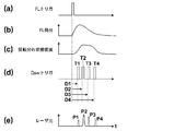
- FIG. 7 is a timing chart showing the relationship between the delay time and the intensity of the laser beam.
- 7A shows the timing of the flash lamp (FL) trigger
- FIG. 7B shows the time change of the emission intensity of the flash lamp
- FIG. 7C shows the time change of the inversion distribution state density in the laser rod.
- (d) shows the timing of the Q switch (Qsw) trigger
- (e) shows the pulse laser beam output corresponding to each timing of the Q switch trigger. That is, in (d) and (e), when the Q switch trigger is output at the timing T1 of the delay time D1, the pulse laser beam P1 is output, and when the Q switch trigger is output at the timing T2 of the delay time D2.
- the pulse laser beam P2 When the pulse laser beam P2 is output and the Q switch trigger is output at the timing T3 of the delay time D3, the pulse laser beam P3 is output, and the Q switch trigger is output at the timing T4 of the delay time D4 Indicates that the pulsed laser beam P4 is output.
- the flash lamp when a flash lamp trigger is transmitted from the control circuit 62, the flash lamp emits light in conjunction with it.
- the light emission intensity of the flash lamp increases for a while after the light emission, and starts to decrease after reaching a peak at a certain time.
- an inversion distribution is formed according to the amount of light absorbed, so the density of states of the inversion distribution also increases with the passage of time. It decreases gradually and then decreases greatly. That is, since the density of states of the inversion distribution changes with time, the intensity of the laser oscillation light varies depending on the timing at which the Q switch trigger is issued. For example, in FIG.
- the pulse laser beam P2 having the maximum intensity is obtained at the timing T2 when the inversion distribution state density is the highest, and the intensity of the pulse laser beam (P1 ⁇ P4) as the inversion distribution state density becomes smaller.
- ⁇ P3) is decreasing. That is, the delay time D2 is a delay time at which the light intensity is the maximum possible intensity, and the delay times D1, D3, and D4 are delay times at which the light intensity is less than the maximum possible intensity. Generally, the delay time D2 is about 150 to 200 ⁇ s.
- the time difference between adjacent Q switch triggers (that is, the difference between the delay times D1 and D2, the difference between the delay times D2 and D3, and the delay times D3 and D4).
- FIG. 8 is a graph showing how the relationship between excitation energy and laser light intensity changes according to the delay time.
- D10 to D40 are graphs showing the intensity of light of the second wavelength
- X is a graph showing the intensity of light of the first wavelength.
- D10 is a graph showing the light intensity at the delay time D1
- D20 is a graph showing the light intensity at the delay time D2
- D30 is the light intensity at the delay time D3.
- D40 is a graph showing the light intensity at the delay time D4.
- the graph of D20 is a graph which gives the maximum intensity
- the intensity I2 of the second wavelength light can be controlled within a range less than the maximum possible intensity. , it is possible to lower further below the damage threshold I th.
- the second wavelength must always have a higher gain than the first wavelength in order to enable wavelength switching. Therefore, the oscillation threshold excitation energy E 2 for the second wavelength is set the delay time to be smaller than the oscillation threshold excitation energy E 1 for the first wavelength.
- the excitation energy is lowered in the normal setting (for example, the delay time D2) because the excitation energy has the lower limit E min even if the intensity of light of each wavelength is made uniform.
- the intensity of light of each wavelength may not be uniform. Therefore, even in such a case, for example, if the setting of the delay time is changed from D2 to D4, the intensities I 1 and I 2 of the light of each wavelength can be made equal with the excitation energies E 3 and E 0 equal to or higher than E min it can.
- the fact that the intensities of the light of each wavelength are equal or equal means that the difference in intensity of the light of each wavelength is within 10% based on the light intensity of the first wavelength.
- the setting of the delay time related to the oscillation of the light of the second wavelength has been described. However, the setting of the delay time related to the oscillation of the light of the first wavelength may be changed.
- FIG. 9 is a timing chart regarding the emission of the excitation lamp, the voltage applied to the Q switch, and the output of the laser beam.
- the control circuit 62 transmits a flash lamp (excitation lamp) trigger to turn on the flash lamp 52 at time t1 (a).
- the control circuit 62 applies the first voltage to the first Q switch 58 (Q-sw1) before the flash lamp 52 is lit (b), and applies the first voltage to the second Q switch 60 (Q-sw2).
- the applied voltage is set to 0 V (third voltage) (c).
- the time for applying the first voltage to the first Q switch 58 may be a time slightly before the time t1.
- the first voltage may be continuously applied to the first Q switch 58 after the previous pulse laser beam emission.
- the first Q switch 58 functions as a quarter wavelength plate.
- the second Q switch 60 by not applying a voltage to the second Q switch 60, the polarization state of the light passing through the second Q switch 60 does not change.
- the laser rod 51 When the laser rod 51 is excited at time t1, p-polarized light is emitted from the laser rod 51.
- the light emitted from the laser rod 51 in the direction of the first mirror 53 reciprocates through the first Q switch 58 functioning as a quarter-wave plate, the polarization direction is rotated by 90 °, and passes through the polarizer 59. Cannot be returned to the laser rod 51.
- the light having a wavelength of 755 nm has a predetermined polarization axis because the polarization direction rotates 90 ° by reciprocating the quarter-wave plate 61. It does not contribute to the laser oscillation of the laser rod 51. Therefore, the Q values of the first resonator C1 and the second resonator C2 are in a low Q state, and the first resonator C1 and the second resonator C2 do not oscillate.
- the control circuit 62 transmits an instruction to change the applied voltage of the first Q switch 58 as a Q switch trigger, and the applied voltage to the first Q switch 58 at time t2 when the delay time Dx has elapsed from time t1. Is changed from the first voltage to 0 V (second voltage) (b). At this time, the control circuit 62 does not change the voltage applied to the second Q switch 60 at 0 V (c). By changing the voltage applied to the first Q switch 58 to 0V, the Q value of the first resonator C1 changes from the low Q state to the high Q state. On the other hand, the Q value of the second resonator C2 is kept in the low Q state.
- the delay time Dx is a delay time set for oscillation of light with a wavelength of 800 nm, and is set so that, for example, the intensity of light with a wavelength of 800 nm having a low gain becomes the maximum possible intensity.
- the control circuit 62 transmits a flash lamp trigger after emitting pulsed laser light having a wavelength of 800 nm, and turns on the flash lamp 52 at time t3 (a).
- the control circuit 62 applies the first voltage to the first Q switch 58 at a time before time t3 (b), and the Q values of the first resonator C1 and the second resonator C2 are Low Q state.
- the control circuit 62 changes the applied voltage of the first Q switch 58 from the first voltage to 0 V at time t4 when the delay time Dy has elapsed from time t3, and changes the applied voltage of the second Q switch 60 from 0 V. Change to the fourth voltage.
- the applied voltage of the first Q switch 58 and the applied voltage of the second Q switch 60 are changed simultaneously, or the applied voltage of the second Q switch 60 is changed first and then the first Q switch 58
- the delay time Dy is a delay time set independently of the delay time Dx for the oscillation of light having a wavelength of 755 nm.
- the intensity of light having a high gain of 755 nm is less than the maximum possible intensity and the wavelength It is set to be equal to the intensity of light of 800 nm.
- the first Q value changing unit 56 and the second Q value changing unit 57 need only be able to switch between the three states of the first, second, and third driving states, and the first Q value changing unit.
- the specific configurations of 56 and the second Q value changing unit 57 are not limited to those described above.
- the first Q value changing unit 56 may be configured by combining a Pockels cell and a quarter-wave plate in the same manner as the second Q value changing unit 57, or the second Q value changing unit 57 may be Similarly to the first Q value changing unit 56, a Pockels cell and a polarizer may be combined.
- control circuit 62 automatically changes the set values of the respective delay times set for the oscillation of the light having the first wavelength or the second wavelength in accordance with the amount of excitation energy that the flash lamp 52 gives to the laser rod 51. Configuration can be adopted. Thereby, for example, when the target intensity of the output light is determined and the excitation energy must be changed or the excitation energy is not stable, the control circuit 62 changes the excitation energy. If the set value of the delay time is changed so as to cancel out the above, it becomes easy to maintain the target strength. For example, when the excitation light source is the flash lamp 52, the control circuit 62 changes the set value of each delay time according to the charging voltage of the flash lamp based on the relationship between the charging voltage of the flash lamp 52 and the excitation energy amount.
- the control circuit 62 may have a reference table (first reference table) in which the charging voltage is associated with the first or second delay time setting value (or its change amount). , They may have a relational expression associated with them.
- the control circuit 62 measures the charging voltage or reads the setting value of the charging voltage to acquire the value of the charging voltage, and refers to the first reference table to correspond to the first charging voltage corresponding to the acquired charging voltage.
- the setting value (or change amount thereof) of the second delay time is read, and the read setting value is newly set to the first or second delay time (or the read change amount is set to the first or second delay). Applies to time settings).
- control circuit 62 changes the set value of each delay time according to the use period of the excitation light source based on the relationship between the use period (including the use time) of the excitation light source such as the flash lamp 52 and the excitation energy amount. You can also.
- the control circuit 62 may have a reference table (second reference table) in which the use period and the set value (or the amount of change) of the first or second delay time are associated with each other. , They may have a relational expression associated with them.
- control circuit 62 measures the use period and obtains the length thereof, and refers to the second reference table to set the first or second delay time set value corresponding to the obtained use period ( Alternatively, the change amount) is read, and the read set value is newly set to the first or second delay time (or the read change amount is applied to the first or second delay time set value).
- At least one of the first mirror 53, the second mirror 54, and the third mirror 55 may be movable along the optical axis direction.
- the relative distance between the mirrors can be adjusted, and the resonator length of the first resonator C1 and the second resonator can be adjusted.
- the resonator length of C2 can be changed.
- the pulse width of the pulse laser beam having a wavelength of 800 nm and the pulse width of the pulse laser beam having a wavelength of 755 nm are changed. At least one of them can be changed.
- the control circuit 62 includes a reference table (third reference table) in which the resonator length of the first resonator C1 and the set value (or the amount of change) of the delay time Dx are associated with each other.
- a reference table fourth reference table in which the resonator length of the second resonator C2 and the set value (or the amount of change) of the delay time Dy are associated with each other. You may have a relational expression.
- control circuit 62 acquires the resonator length of each resonator from the amount of movement of each mirror, and refers to the third and / or fourth reference table to correspond to the first resonator length corresponding to the acquired resonator length.
- the setting value (or change amount thereof) of the second delay time is read, and the read setting value is newly set to the first or second delay time (or the read change amount is set to the first or second delay). Applies to time settings).
- the laser apparatus 1 is a solid laser medium having an oscillation wavelength at the first wavelength (800 nm) and the second wavelength (755 nm) having higher emission efficiency than the first wavelength.
- a Q-value changing unit (first Q-value changing unit 56 and second Q-value changing unit 57) that includes a changing unit and Q-switch oscillates light of the first or second wavelength, and an excitation unit and a Q-value change
- a control unit for controlling the unit.
- the Q value is changed when the second delay time elapses when the intensity of light of the second wavelength becomes less than the maximum possible intensity after the excitation of the laser medium is started.
- the unit is controlled to cause the light of the second wavelength to oscillate Q-switch. That is, in the laser device 1, the delay time Dx when oscillating the light of the first wavelength and the delay time Dy when oscillating the light of the second wavelength are set independently of each other. As a result, in a laser device using a laser medium having two oscillation wavelengths with different emission efficiencies, the light intensity of each wavelength can be controlled independently by adjusting these delay times without increasing the number of parts of the device. It becomes possible.
- the first mirror 53 and the second mirror 54 constitute a first resonator C1 that oscillates light having a wavelength of 800 nm, and the first mirror 53 and the third mirror 55 A second resonator C2 that oscillates light having a wavelength of 755 nm is configured.
- the laser rod 51 has oscillation wavelengths at a wavelength of 800 nm and a wavelength of 755 nm, and the light emission efficiency at the wavelength 755 nm is higher than the light emission efficiency at the wavelength 800 nm.
- the first Q value changing unit 56 is disposed in a common part to the first resonator C1 and the second resonator C2, and the second Q is changed between the second mirror 54 and the third mirror 55.
- a value changing unit 57 is arranged.
- the Q values of the first resonator C1 and the second resonator C2 can be controlled. Further, by driving the second Q value changing unit 57, only the Q value of the second resonator C2 can be controlled.
- the first Q switch 58 is inserted into the first resonator C1 for a wavelength of 800 nm with a low gain.
- the first Q switch 58 and the second Q switch 60 are inserted into the second resonator C2 for the wavelength 755 nm having a high gain.
- Patent Document 3 two Pockels cells are inserted in the resonators of both wavelengths, and a decrease in output becomes a problem particularly at a wavelength of 800 nm where the gain is low.
- only one Pockels cell is inserted into the first resonator C1, and it is not necessary to arrange a plurality of elements that change the polarization state of light in the first resonator C1, For a wavelength of 800 nm where the laser output is low, it is possible to suppress a decrease in laser output due to the insertion of a plurality of Pockels cells.
- the first resonator C1 and the second resonator C2 are configured on one axis so that the optical axes of the light having a wavelength of 800 nm and the light having a wavelength of 755 nm are parallel to each other.
- the optical member of a mirror and a Q value change part can be used in common with the light of wavelength 800nm and the light of wavelength 755nm.
- the third mirror 55 is arranged on the side farther from the laser rod 51 than the second mirror 54, and the resonator length of the first resonator C1 is the second resonator C2. Shorter than the resonator length. By shortening the resonator length of the first resonator C1, the pulse laser beam can be shortened at a wavelength of 800 nm where the gain is low.
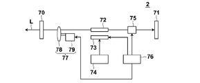
- FIG. 10 is a schematic diagram showing the configuration of the laser apparatus 2 according to the second embodiment.
- the laser apparatus 2 according to the present embodiment has a wavelength selection unit including a plurality of bandpass filters having different transmission wavelengths in the resonator, and selects a wavelength to be oscillated by the wavelength selection unit.
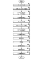
- the laser device 2 includes two mirrors 70 and 71 constituting a resonator, a laser rod 72, a flash lamp 73, a power supply circuit 74, a Q switch 75, a control circuit 76, and a wavelength selection unit 77.
- the laser rod 72 is a laser medium, and as the laser rod 72, for example, an alexandrite crystal can be used as in the first embodiment. Also in this embodiment, for example, the first wavelength with a low gain is 800 nm, and the second wavelength with a high gain is 755 nm.
- the flash lamp 73 is an excitation light source to which a power supply circuit 74 is connected, and irradiates the laser rod 72 with excitation light. A light source other than the flash lamp 73 may be used as the excitation light source.
- the mirrors 70 and 71 are opposed to each other with the laser rod 72 interposed therebetween, and these mirrors constitute a resonator.
- this resonator corresponds to both the first and second wavelengths.
- this resonator oscillates light of both the first and second wavelengths.
- the mirror 70 is the output side.
- a Q switch 75 and a wavelength selector 77 are arranged on the optical path in the resonator. The Q value of the resonator is changed by the Q switch 75.
- a Pockels cell can be used as the Q switch.
- the wavelength selector 77 is used when switching the oscillation wavelength between the first wavelength and the second wavelength.
- the wavelength selection unit 77 includes a plurality of band pass filters (BPFs) 78 having different transmission wavelengths and a drive unit 79 that rotationally drives the band pass filter 78.
- BPFs band pass filters
- the wavelength selector 77 selectively inserts a specific bandpass filter among the plurality of bandpass filters 78 on the optical path of the resonator.
- the wavelength selector 77 includes, for example, a first bandpass filter that transmits light having a center wavelength of 755 nm, and a second bandpass filter that transmits light having a center wavelength of 800 nm.
- the first and second band-pass filters are composed of rotating bodies arranged in an angular range of 0 ° to 180 ° and an angular range of 180 ° to 360 °, for example, and are transmitted along with rotational displacement.
- the light to be changed is configured to change.
- the oscillation wavelength can be set to 755 nm by inserting the first band pass filter on the optical path of the resonator while rotating the rotating body, and the second band pass filter can be set on the optical path of the resonator. By inserting, the oscillation wavelength can be set to 800 nm.
- the driving unit 79 rotationally drives a plurality of bandpass filters 78 formed of a rotating body so that the bandpass filters inserted on the optical path of the resonator are sequentially switched. Further, the rotation state indicating which band pass filter is on the optical path is detected by, for example, a rotary encoder (not shown).
- the control circuit 76 transmits a flash lamp trigger for controlling the light emission of the flash lamp 73, and irradiates the laser rod 72 with the excitation light from the flash lamp 73.
- the control circuit 76 monitors the state of the BPF and transmits a flash lamp trigger based on the state. For example, the control circuit 76 determines that the BPF state is a delay time from the excitation of the laser medium to the Q-switch oscillation from the driving position of the rotating body where the bandpass filter corresponding to the wavelength of the light to be emitted is inserted in the optical path.
- a flash lamp trigger is transmitted when the amount of displacement of the rotating body is subtracted during this period. This delay time is set for each wavelength of light to be emitted.
- the delay time for the wavelength of 800 nm is set so that the light intensity becomes the maximum possible intensity
- the delay time for the wavelength 755 nm is set so that the light intensity is less than the maximum possible intensity.
- the control circuit 76 transmits a Q switch trigger to the Q switch 75 when a delay time set for each wavelength of light to be emitted elapses. Light is output from the mirror 70 on the output side when the Q switch 75 suddenly changes the resonator from the low Q state to the high Q state in response to the Q switch trigger (by turning on the Q switch).
- the laser apparatus 2 is a solid laser medium having an oscillation wavelength at the first wavelength (800 nm) and the second wavelength (755 nm) having higher emission efficiency than the first wavelength.
- Laser rod 72 excitation unit (flash lamp 73), and first resonator (mirrors 70 and 71) that oscillates light of the first wavelength and has a laser medium on the internal optical path.
- a second resonator (mirrors 70 and 71) that oscillates light of the second wavelength and has a common optical path with the first resonator including the optical path in which the laser medium is disposed;
- a Q value changing unit (Q switch 75) that includes at least a Q value changing unit disposed on the common optical path and Q-oscillates light having the first or second wavelength, and controls the excitation unit and the Q value changing unit.
- Control unit (control circuit 76) Obtain. Then, when the oscillation wavelength is the first wavelength, the control unit controls the Q value changing unit when the first delay time has elapsed after the excitation of the laser medium, and switches the light of the first wavelength to the Q switch.
- the Q value is changed when the second delay time elapses when the intensity of light of the second wavelength becomes less than the maximum possible intensity after the excitation of the laser medium is started.
- the unit is controlled to cause the light of the second wavelength to oscillate Q-switch. That is, in the laser device 2, the delay time when oscillating the light of the first wavelength and the delay time when oscillating the light of the second wavelength are set independently of each other. As a result, in a laser device using a laser medium having two oscillation wavelengths with different emission efficiencies, the light intensity of each wavelength can be controlled independently by adjusting these delay times without increasing the number of parts of the device. It becomes possible.
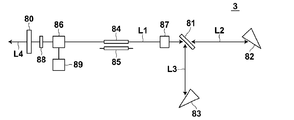
- FIG. 11 is a schematic diagram illustrating a configuration of a laser apparatus 3 according to the third embodiment.
- the laser device 3 according to the present embodiment oscillates at a plurality of wavelengths using a branching polarizer and a resonant optical path selector.
- the laser device 3 includes an output side mirror 80, a polarizer 81, a first reflecting prism 82, a second reflecting prism 83, a laser rod 84, a flash lamp 85, two Pockels cells 86 and 87, ⁇ / 4 wavelength plate 88 and trigger controller 89.
- a laser rod 84 and a flash lamp 85 are arranged between the mirror 80 and the polarizer 81.
- the laser rod 84 is a laser medium, and as the laser rod 84, for example, an alexandrite crystal can be used as in the first embodiment. Also in this embodiment, for example, the first wavelength with a low gain is 800 nm, and the second wavelength with a high gain is 755 nm.
- the flash lamp 85 is an excitation light source, and irradiates the laser rod 84 with excitation light in conjunction with the flash lamp trigger transmitted from the control circuit 89. A light source other than the flash lamp 85 may be used as the excitation light source.
- a Pockels cell 87 constituting a resonance optical path selection unit is disposed.
- the Pockels cell 87 is applied with a voltage for rotating the polarization direction of the incident linearly polarized light by 90 ° when oscillating at a wavelength of 800 nm, and is not applied when oscillating at a wavelength of 755 nm.
- a polarizer 81 which is an optical path branching unit transmits p-polarized light and reflects s-polarized light. The light transmitted through the polarizer 81 travels along the first branch optical path L2 and is reflected by the first reflecting prism 82. On the other hand, the light reflected by the polarizer 81 travels along the second branch optical path L3 and is reflected by the second reflecting prism 83.
- the first reflecting prism 82 is arranged to have a Brewster angle with respect to the incident light.
- the first reflecting prism 82 has a dielectric reflecting film that selectively reflects light having a wavelength of 755 nm.
- the second reflecting prism 83 has a dielectric reflecting film that selectively reflects light having a wavelength of 800 nm.
- the mirror 80 and the second reflecting prism 83 constitute a resonator (first resonator) having a wavelength of 800 nm.
- the mirror 80 and the first reflecting prism 82 constitute a resonator (second resonator) having a wavelength of 755 nm. These resonators have a common optical path L1.
- a Q switch composed of a Pockels cell 86 and a ⁇ / 4 wavelength plate 88 is also arranged on the common optical path L1.
- the voltage applied to the Pockels cell 86 is controlled by the control circuit 89.
- the flash lamp 85 When the flash lamp 85 is turned on, no voltage is applied to the Pockels cell 86 constituting the Q switch, and the Q switch is off.
- the Q switch After the flash lamp 85 is turned on, the Q switch is turned on when a predetermined delay time elapses. Thereby, laser oscillation occurs in the first resonator or the second resonator according to the state of the Pockels cell 87, and light is output from the mirror 80.
- the delay time is set for each wavelength of light to be emitted. For example, the delay time for the wavelength of 800 nm is set so that the light intensity becomes the maximum possible intensity, and the delay time for the wavelength 755 nm is set so that the light intensity is less than the maximum possible intensity.
- the p-polarized light emitted from the laser rod 84 passes through the Pockels cell 87 as p-polarized light and transmits the p-polarized light 81. , Passes through the first branch optical path L2, and is reflected by the first reflecting prism 82.
- the light reflected by the first reflecting prism 82 passes through the polarizer 81 and the Pockels cell 87 in the opposite direction as p-polarized light, enters the laser rod 84, causes laser oscillation, and outputs laser light L4.
- the first reflecting prism 82 selectively reflects light having a wavelength of 755 nm, so that light having a wavelength of 755 nm oscillates.
- the p-polarized light emitted from the laser rod 84 is rotated by 90 ° when the polarization direction is transmitted through the Pockels cell 87. It becomes polarized light.
- the s-polarized light is reflected by the polarizer 81, passes through the second branch optical path L3, and is reflected by the second reflecting prism 83.
- the light reflected by the second reflecting prism 83 passes through the polarizer 81 in the reverse direction and enters the Pockels cell 87 in the reverse direction.
- the light that has entered the Pockels cell 87 with s-polarized light has its polarization direction rotated by 90 ° when passing through the Pockels cell 87, becomes p-polarized light, and enters the laser rod 84, causing laser oscillation, and the laser light L4 is generated. Is output.
- the second reflecting prism 83 selectively reflects light having a wavelength of 800 nm, so that light having a wavelength of 800 nm oscillates.
- the laser apparatus 3 is a solid laser medium having an oscillation wavelength at the first wavelength (800 nm) and the second wavelength (755 nm) having higher emission efficiency than the first wavelength.
- Laser rod 84 excitation unit (flash lamp 85), and first resonator that oscillates light of the first wavelength and has a laser medium on the internal optical path (mirror 80 and reflecting prism) 83) and a second resonator (mirror 80 and reflecting prism) having a common optical path with the first resonator including the optical path in which the laser medium is disposed, the resonator oscillating light of the second wavelength.
- a Q-value changing unit (Q switch 86) that includes at least a Q-value changing unit disposed on the common optical path, Q-oscillates light of the first or second wavelength, a pumping unit, and a Q-value changing Control system Parts and a (control circuit 89). Then, when the oscillation wavelength is the first wavelength, the control unit controls the Q value changing unit when the first delay time has elapsed after the excitation of the laser medium, and switches the light of the first wavelength to the Q switch. When oscillation is performed and the oscillation wavelength is the second wavelength, the Q value is changed when the second delay time elapses when the intensity of light of the second wavelength becomes less than the maximum possible intensity after the excitation of the laser medium is started.
- the unit is controlled to cause the light of the second wavelength to oscillate Q-switch. That is, in the laser device 3, the delay time for oscillating the light of the first wavelength and the delay time for oscillating the light of the second wavelength are set independently of each other. As a result, in a laser device using a laser medium having two oscillation wavelengths with different emission efficiencies, the light intensity of each wavelength can be controlled independently by adjusting these delay times without increasing the number of parts of the device. It becomes possible.
- control unit sets each delay time set for the oscillation of light of the first wavelength or the second wavelength according to the excitation energy amount and the resonator length. It is possible to adopt a configuration that automatically changes.
- FIG. 12 is a schematic diagram illustrating a configuration of the photoacoustic measurement apparatus 10 according to the embodiment.
- the photoacoustic measuring device 10 includes an ultrasonic probe (probe) 11, an ultrasonic unit 12, and a laser light source unit 13 including the laser device of the present invention.
- the laser light source unit 13 emits pulsed laser light that irradiates the subject.
- the laser light source unit 13 emits laser light having a plurality of wavelengths including the first wavelength and the second wavelength.
- the laser light source unit 13 includes, for example, the laser device 1 according to the first embodiment and a light guide unit (for example, an optical fiber) that guides the laser light emitted from the laser device 1.
- the laser light emitted from the laser light source unit 13 is guided to the probe 11 using the light guide means, and is irradiated from the probe 11 toward the subject.
- the irradiation position of the laser beam is not particularly limited, and the laser beam may be irradiated from a place other than the probe 11.
- an ultrasonic wave photoacoustic wave
- the probe 11 includes an ultrasonic detector.
- the probe 11 has, for example, a plurality of ultrasonic detector elements (ultrasonic transducers) arranged in a one-dimensional manner, and an acoustic wave (light) from within the subject by the ultrasonic transducers arranged in a one-dimensional manner. Sound signal).
- ultrasonic detector elements ultrasonic transducers
- acoustic wave light
- the ultrasonic unit 12 includes a reception circuit 21, an AD conversion unit 22, a reception memory 23, a complex number conversion unit 24, a photoacoustic image reconstruction unit 25, a phase information extraction unit 26, an intensity information extraction unit 27, and a detection / logarithmic conversion unit 28. , A photoacoustic image construction means 29, a trigger control circuit 30, and a control means 31.
- the receiving circuit 21 receives the photoacoustic signal detected by the probe 11.
- the AD conversion unit 22 is a detection unit that samples the photoacoustic signal received by the receiving circuit 21 and generates photoacoustic data that is digital data.
- the AD conversion means 22 samples the photoacoustic signal at a predetermined sampling period in synchronization with the AD clock signal.
- the AD conversion means 22 stores the photoacoustic data in the reception memory 23.
- the AD conversion means 22 stores photoacoustic data corresponding to each wavelength of the pulsed laser light emitted from the laser light source unit 13 in the reception memory 23. That is, the AD conversion means 22 has the first photoacoustic data obtained by sampling the photoacoustic signal detected by the probe 11 when the subject is irradiated with the pulse laser beam having the first wavelength, and the second wavelength.
- the second photoacoustic data obtained by sampling the photoacoustic signal detected by the probe 11 when the pulse laser beam is irradiated is stored in the reception memory 23.
- the complex number conversion means 24 reads the first photoacoustic data and the second photoacoustic data from the reception memory 23, and generates complex number data in which one is a real part and the other is an imaginary part. In the following description, it is assumed that the complex number converting means 24 generates complex number data having the first photoacoustic data as an imaginary part and the second photoacoustic data as a real part.
- the photoacoustic image reconstruction unit 25 inputs complex number data from the complex number conversion unit 24.
- the photoacoustic image reconstruction means 25 performs image reconstruction from the input complex number data by the Fourier transform method (FTA method).
- FFA method Fourier transform method
- For image reconstruction by the Fourier transform method for example, a conventionally known method described in the document “Photoacoustic Image Reconstruction-A A Quantitative Analysis” Jonathan I I Sperl I et al. SPIE-OSA Vol. it can.
- the photoacoustic image reconstruction unit 25 inputs Fourier transform data indicating the reconstructed image to the phase information extraction unit 26 and the intensity information extraction unit 27.
- the phase information extraction means 26 extracts the relative magnitude of the relative signal intensity between the photoacoustic data corresponding to each wavelength.
- the phase information extraction unit 26 uses the reconstructed image reconstructed by the photoacoustic image reconstruction unit 25 as input data, and compares the real part and the imaginary part from the input data that is complex data. In comparison, phase information indicating which is relatively large is generated.
- the intensity information extraction unit 27 generates intensity information indicating the signal intensity based on the photoacoustic data corresponding to each wavelength.
- the intensity information extraction unit 27 uses the reconstructed image reconstructed by the photoacoustic image reconstruction unit 25 as input data, and generates intensity information from the input data that is complex number data. For example, when the complex number data is represented by X + iY, the intensity information extraction unit 27 extracts (X 2 + Y 2 ) 1/2 as the intensity information.
- the detection / logarithm conversion means 28 generates an envelope of data indicating the intensity information extracted by the intensity information extraction means 27, and then logarithmically converts the envelope to widen the dynamic range.
- the photoacoustic image construction unit 29 receives the phase information from the phase information extraction unit 26 and the intensity information after the detection / logarithmic conversion processing from the detection / logarithmic conversion unit 28.
- the photoacoustic image construction unit 29 generates a photoacoustic image that is a distribution image of the light absorber based on the input phase information and intensity information.
- the photoacoustic image construction unit 29 determines the luminance (gradation value) of each pixel in the distribution image of the light absorber based on the input intensity information.
- the photoacoustic image construction means 29 determines the color (display color) of each pixel in the light absorber distribution image based on, for example, phase information.
- the photoacoustic image construction unit 29 determines the color of each pixel based on the input phase information using, for example, a color map in which a phase range of 0 ° to 90 ° is associated with a predetermined color.
- the range of the phase from 0 ° to 45 ° is a range in which the second photoacoustic data is larger than the first photoacoustic data. Therefore, the source of the photoacoustic signal is 755 nm in wavelength rather than absorption for the wavelength of 798 nm. It is considered that this is a vein through which blood mainly containing deoxygenated hemoglobin flows.
- the range of 45 ° to 90 ° is a range in which the first photoacoustic data is larger than the second photoacoustic data
- the source of the photoacoustic signal is for the wavelength 755 nm rather than the absorption for the wavelength 798 nm. It is considered to be an artery through which blood mainly containing oxygenated hemoglobin is flowing.
- the phase gradually changes so that the phase is 0 ° in blue and the phase becomes colorless (white) as the phase approaches 45 °, and the phase 90 ° is red and the phase is 45.
- the portion corresponding to the artery can be represented in red
- the portion corresponding to the vein can be represented in blue.
- the gradation value may be constant and only the color classification of the portion corresponding to the artery and the portion corresponding to the vein may be performed according to the phase information.
- the image display means 14 displays the photoacoustic image generated by the photoacoustic image construction means 29 on the display screen.
- the control means 31 controls each part in the ultrasonic unit 12.
- the trigger control circuit 30 outputs a flash lamp trigger for controlling the light emission of the flash lamp 52 (see FIG. 1) to the laser light source unit 13.
- the control circuit 62 of the laser light source unit 13 transmits the flash lamp trigger to the flash lamp 52 to turn on the flash lamp 52, and the flash lamp 52 excites the laser rod 51. Irradiate light.
- the control circuit 62 of the laser light source unit 13 outputs a Q switch trigger to the first Q value changing unit 56 or the second Q value changing unit 57 when the delay time set for each wavelength has elapsed after the output of the flash lamp trigger. Output.
- the control circuit 62 changes the Q value of the first resonator from the low Q state to the high Q state when the oscillation wavelength is 800 nm.
- the oscillation wavelength is 755 nm, the Q values of the first resonator and the second resonator are changed from the low Q state to the high Q state.
- the trigger control circuit 30 outputs a sampling trigger (AD trigger) to the AD conversion means 22 in accordance with the timing of the Q switch trigger, that is, the emission timing of the pulse laser beam.
- the AD conversion unit 22 starts sampling of the photoacoustic signal based on the sampling trigger.
- FIG. 13 shows an operation procedure of the photoacoustic measurement apparatus 10.
- the trigger control circuit 30 When the trigger control circuit 30 is ready to receive the photoacoustic signal, the trigger control circuit 30 outputs a flash lamp trigger to the laser light source unit 13 in order to emit pulsed laser light having the first wavelength (800 nm) (step S1).
- the control circuit 62 of the laser light source unit 13 Before receiving the flash lamp trigger, the control circuit 62 of the laser light source unit 13 applies the first voltage to the first Q switch 58 and puts the first resonator C1 and the second resonator C2 into the low Q state. I have to.
- the control circuit 62 turns on the flash lamp 52 in response to the flash lamp trigger from the trigger control circuit 30 and excites the laser rod 51 (step S2).
- the control circuit 62 After the output of the flash lamp trigger, the control circuit 62 outputs a Q switch trigger to the first Q value changing unit 56 or the second Q value changing unit 57 when the delay time set for each wavelength has elapsed.
- the voltage applied to the Q switch 58 is changed from the first voltage to 0 V (step S3).
- the control circuit 62 applies 0 V to the second Q switch 60, and the first resonator C1 is controlled to the high Q state and the second resonator C2 is controlled to the low Q state. Of the first resonator and the second resonator, only the first resonator enters the high Q state, so that the laser light source unit 13 emits a pulsed laser beam having a wavelength of 800 nm.
- the control circuit 62 also transmits a Q switch trigger to the trigger control circuit 30 to convey the timing of the Q switch.
- the pulsed laser light having a wavelength of 800 nm emitted from the laser light source unit 13 is guided to, for example, the probe 11 and irradiated from the probe 11 to the subject.
- a photoacoustic signal is generated by the light absorber absorbing the energy of the irradiated pulsed laser light.
- the probe 11 detects a photoacoustic signal generated in the subject.
- the photoacoustic signal detected by the probe 11 is received by the receiving circuit 21.
- the trigger control circuit 30 outputs a sampling trigger to the AD conversion means 22 in accordance with the timing of the Q switch.
- the AD conversion means 22 samples the photoacoustic signal received by the receiving circuit 21 at a predetermined sampling period (step S4).
- the photoacoustic signal sampled by the AD conversion means 22 is stored in the reception memory 23 as first photoacoustic data.
- the trigger control circuit 30 When the trigger control circuit 30 is ready to receive the next photoacoustic signal, the trigger control circuit 30 outputs a flash lamp trigger to the laser light source unit 13 in order to emit pulsed laser light having the second wavelength (755 nm) (step S5).
- the control circuit 62 Prior to receiving the flash lamp trigger, the control circuit 62 applies a first voltage to the first Q switch 58 to place the first resonator and the second resonator in a low Q state.
- the control circuit 62 turns on the flash lamp 52 in response to the flash lamp trigger from the trigger control circuit 30 and excites the laser rod 51 (step S6).
- the control circuit 62 outputs the Q switch trigger to the first Q value changing unit 56 or the second Q value changing unit 57 when the delay time set for each wavelength has elapsed after the output of the flash lamp trigger. Then, the control circuit 62 changes the voltage applied to the first Q switch 58 from the first voltage to 0V, and changes the voltage applied to the second Q switch 60 from 0V to the fourth voltage (step S7). ). At this time, the control circuit 62 changes the applied voltage simultaneously with the first Q switch 58 and the second Q switch 60, or changes the applied voltage of the second Q switch 60 first and then changes the first applied voltage. The applied voltage of the Q switch 58 is changed.
- both the first resonator C1 and the second resonator C2 are in a high Q state.
- the laser gain is oscillated at a wavelength of 755 nm, and the laser light source unit 13 emits a pulsed laser beam having a wavelength of 755 nm.
- the pulsed laser beam having a wavelength of 755 nm emitted from the laser light source unit 13 is guided to, for example, the probe 11 and irradiated from the probe 11 to the subject.
- a photoacoustic signal is generated by the light absorber absorbing the energy of the irradiated pulsed laser light.
- the probe 11 detects a photoacoustic signal generated in the subject.
- the photoacoustic signal detected by the probe 11 is received by the receiving circuit 21.
- the trigger control circuit 30 outputs a sampling trigger to the AD conversion means 22 in accordance with the timing of the Q switch.
- the AD conversion means 22 samples the photoacoustic signal received by the receiving circuit 21 at a predetermined sampling period (step S88).
- the photoacoustic signal sampled by the AD conversion means 22 is stored in the reception memory 23 as second photoacoustic data.
- the first and second photoacoustic data are stored in the reception memory, so that data necessary for generating a photoacoustic image for one frame is prepared.
- generates a photoacoustic image is divided
- the complex numbering means 24 reads the first photoacoustic data and the second photoacoustic data from the reception memory 23, sets the first photoacoustic image data as an imaginary part, and sets the second photoacoustic image data as a real part.
- the complex data is generated (step S9).
- the photoacoustic image reconstruction means 25 performs image reconstruction by the Fourier transform method (FTA method) from the complex number data converted into the complex number in step S9 (step S10).
- FFA method Fourier transform method
- the intensity information extraction means 27 extracts intensity information from the reconstructed complex number data (step S12). For example, when the reconstructed complex number data is represented by X + iY, the intensity information extraction unit 27 extracts (X 2 + Y 2 ) 1/2 as the intensity information.
- the detection / logarithmic conversion means 28 performs detection / logarithmic conversion processing on the intensity information extracted in step S12.
- the photoacoustic image construction unit 29 generates a photoacoustic image based on the phase information extracted in step S11 and the intensity information extracted in step S12 subjected to detection / logarithmic conversion processing ( Step S13). For example, the photoacoustic image construction unit 29 determines the luminance (gradation value) of each pixel in the distribution image of the light absorber based on the intensity information, and determines the color of each pixel based on the phase information. An acoustic image is generated. The generated photoacoustic image is displayed on the image display means 14.
- the object is alternately irradiated with light having a wavelength of 800 nm and light having a wavelength of 755 nm.
- the repetition frequency of oscillation with a wavelength of 800 nm may be higher than the repetition frequency of oscillation with a wavelength of 755 nm.
- light having a wavelength of 755 nm may be emitted from the laser light source unit 13 and then light having a wavelength of 800 nm may be continuously emitted a plurality of times.
- a photoacoustic signal for light having a wavelength of 800 nm may be acquired a plurality of times, and a process such as addition averaging may be performed on the plurality of photoacoustic signals.
- the signal-to-noise ratio of a photoacoustic image having a wavelength of 800 nm can be increased.
- the photoacoustic measurement device 10 according to the present embodiment uses the laser device 1 according to the first embodiment, the same effects as those of the first embodiment can be obtained.
- complex number data in which one of the first photoacoustic data and the second photoacoustic data obtained at two wavelengths is a real part and the other is an imaginary part is generated.
- a reconstructed image is generated from the complex number data by Fourier transform.
- reconstruction can be performed more efficiently than when the first photoacoustic data and the second photoacoustic data are reconstructed separately.
- an ultrasonic wave is transmitted from the probe 11 to the subject, and a reflected acoustic wave image is generated based on a reflected wave signal of the transmitted acoustic wave (ultrasonic wave).
- Photoacoustic measuring device 1, 2, 3 Laser device 10 Photoacoustic measuring device 11 Probe 12 Ultrasonic unit 13 Laser light source unit 14 Image display means 21 Reception circuit 22 Conversion means 23 Reception memory 24 Complex numbering means 25 Photoacoustic image reconstruction means 26 Phase information extraction Means 27 Intensity information extraction means 28 Detection / logarithm conversion means 29 Photoacoustic image construction means 30 Trigger control circuit 31 Control means 51 Laser rod 52 Flash lamps 53, 54, 55 Mirror 56, 57 Q value changing unit 62 Control circuit C1 Resonator C2 Cavity L Laser light
Landscapes
- Physics & Mathematics (AREA)
- Electromagnetism (AREA)
- Engineering & Computer Science (AREA)
- Plasma & Fusion (AREA)
- Optics & Photonics (AREA)
- Life Sciences & Earth Sciences (AREA)
- Health & Medical Sciences (AREA)
- Biomedical Technology (AREA)
- Surgery (AREA)
- Pathology (AREA)
- Acoustics & Sound (AREA)
- Heart & Thoracic Surgery (AREA)
- Medical Informatics (AREA)
- Molecular Biology (AREA)
- Biophysics (AREA)
- Animal Behavior & Ethology (AREA)
- General Health & Medical Sciences (AREA)
- Public Health (AREA)
- Veterinary Medicine (AREA)
- Chemical & Material Sciences (AREA)
- Crystallography & Structural Chemistry (AREA)
- Lasers (AREA)
- Ultra Sonic Daignosis Equipment (AREA)
Priority Applications (3)
| Application Number | Priority Date | Filing Date | Title |
|---|---|---|---|
| CN201580016006.0A CN106134020B (zh) | 2014-03-27 | 2015-02-05 | 激光装置及具备该激光装置的光声测量装置 |
| EP15768938.1A EP3125378B1 (en) | 2014-03-27 | 2015-02-05 | Laser device and optoacoustic measurement device equipped with same |
| US15/275,697 US10243318B2 (en) | 2014-03-27 | 2016-09-26 | Laser device and photoacoustic measurement device comprising the same |
Applications Claiming Priority (2)
| Application Number | Priority Date | Filing Date | Title |
|---|---|---|---|
| JP2014065958A JP6033252B2 (ja) | 2014-03-27 | 2014-03-27 | レーザ装置及びそれを備えた光音響計測装置 |
| JP2014-065958 | 2014-03-27 |
Related Child Applications (1)
| Application Number | Title | Priority Date | Filing Date |
|---|---|---|---|
| US15/275,697 Continuation US10243318B2 (en) | 2014-03-27 | 2016-09-26 | Laser device and photoacoustic measurement device comprising the same |
Publications (1)
| Publication Number | Publication Date |
|---|---|
| WO2015146306A1 true WO2015146306A1 (ja) | 2015-10-01 |
Family
ID=54194845
Family Applications (1)
| Application Number | Title | Priority Date | Filing Date |
|---|---|---|---|
| PCT/JP2015/053270 Ceased WO2015146306A1 (ja) | 2014-03-27 | 2015-02-05 | レーザ装置及びそれを備えた光音響計測装置 |
Country Status (5)
| Country | Link |
|---|---|
| US (1) | US10243318B2 (enExample) |
| EP (1) | EP3125378B1 (enExample) |
| JP (1) | JP6033252B2 (enExample) |
| CN (1) | CN106134020B (enExample) |
| WO (1) | WO2015146306A1 (enExample) |
Families Citing this family (6)
| Publication number | Priority date | Publication date | Assignee | Title |
|---|---|---|---|---|
| WO2017169452A1 (ja) * | 2016-03-30 | 2017-10-05 | 富士フイルム株式会社 | レーザ装置および光音響計測装置 |
| WO2018096770A1 (ja) * | 2016-11-25 | 2018-05-31 | 富士フイルム株式会社 | 光音響計測装置 |
| AT520793B1 (de) * | 2017-12-28 | 2021-02-15 | Avl List Gmbh | Messvorrichtung zur Ermittlung einer Messgröße eines Messgases |
| JP6964759B2 (ja) | 2018-03-29 | 2021-11-10 | 富士フイルム株式会社 | 多波長レーザ装置及び光音響計測装置 |
| CN110086071A (zh) * | 2019-05-24 | 2019-08-02 | 长春理工大学 | 一种双波长激光可控输出方法及激光器 |
| KR102221082B1 (ko) * | 2020-02-13 | 2021-02-26 | (주)엘트라글로벌 | 다중 큐 스위칭을 이용한 다중 레이저 펄스 발진 방법 및 다중 레이저 펄스 발진 장치 |
Citations (6)
| Publication number | Priority date | Publication date | Assignee | Title |
|---|---|---|---|---|
| US6078606A (en) * | 1975-03-17 | 2000-06-20 | Lockheed Martin Corporation | Multi-color, multi-pulse laser |
| JP2005072131A (ja) * | 2003-08-21 | 2005-03-17 | Ishikawajima Harima Heavy Ind Co Ltd | レーザ発振器 |
| JP2005158790A (ja) * | 2003-11-20 | 2005-06-16 | Laserfront Technologies Inc | パルス駆動レーザダイオード励起qスイッチ固体レーザ発振器並びにその発振制御方法 |
| JP2013089680A (ja) * | 2011-10-14 | 2013-05-13 | Canon Inc | レーザー装置およびその制御方法 |
| JP2013214703A (ja) * | 2012-03-09 | 2013-10-17 | Fujifilm Corp | レーザ装置及び光音響計測装置 |
| WO2015001876A1 (ja) * | 2013-07-05 | 2015-01-08 | 富士フイルム株式会社 | レーザ装置及び光音響計測装置 |
Family Cites Families (8)
| Publication number | Priority date | Publication date | Assignee | Title |
|---|---|---|---|---|
| DE3704338C2 (de) * | 1987-02-12 | 1995-04-06 | Gsf Forschungszentrum Umwelt | Einrichtung zur Erzeugung verschiedener Laserwellenlängen aus demselben Lasermedium |
| JP4406226B2 (ja) | 2003-07-02 | 2010-01-27 | 株式会社東芝 | 生体情報映像装置 |
| CN1635672A (zh) * | 2003-12-31 | 2005-07-06 | 中国科学院福建物质结构研究所 | 四波长电光调q脉冲激光器 |
| CN1702925A (zh) * | 2005-06-13 | 2005-11-30 | 山东师范大学 | 一种间歇振荡双波长全固态激光器 |
| CN1983746A (zh) * | 2005-12-16 | 2007-06-20 | 中国科学院福建物质结构研究所 | 一种多波长调q激光器 |
| JP5460000B2 (ja) | 2008-08-20 | 2014-04-02 | キヤノン株式会社 | イメージング装置およびイメージング方法 |
| US8385382B2 (en) * | 2011-03-22 | 2013-02-26 | The United States Of America As Represented By The Secretary Of The Army | Compact multi-wavelength and multi-beam laser |
| EP2822113A3 (en) * | 2013-06-28 | 2015-03-25 | Canon Kabushiki Kaisha | Pulse laser and photoacoustic apparatus |
-
2014
- 2014-03-27 JP JP2014065958A patent/JP6033252B2/ja active Active
-
2015
- 2015-02-05 EP EP15768938.1A patent/EP3125378B1/en active Active
- 2015-02-05 WO PCT/JP2015/053270 patent/WO2015146306A1/ja not_active Ceased
- 2015-02-05 CN CN201580016006.0A patent/CN106134020B/zh active Active
-
2016
- 2016-09-26 US US15/275,697 patent/US10243318B2/en active Active
Patent Citations (6)
| Publication number | Priority date | Publication date | Assignee | Title |
|---|---|---|---|---|
| US6078606A (en) * | 1975-03-17 | 2000-06-20 | Lockheed Martin Corporation | Multi-color, multi-pulse laser |
| JP2005072131A (ja) * | 2003-08-21 | 2005-03-17 | Ishikawajima Harima Heavy Ind Co Ltd | レーザ発振器 |
| JP2005158790A (ja) * | 2003-11-20 | 2005-06-16 | Laserfront Technologies Inc | パルス駆動レーザダイオード励起qスイッチ固体レーザ発振器並びにその発振制御方法 |
| JP2013089680A (ja) * | 2011-10-14 | 2013-05-13 | Canon Inc | レーザー装置およびその制御方法 |
| JP2013214703A (ja) * | 2012-03-09 | 2013-10-17 | Fujifilm Corp | レーザ装置及び光音響計測装置 |
| WO2015001876A1 (ja) * | 2013-07-05 | 2015-01-08 | 富士フイルム株式会社 | レーザ装置及び光音響計測装置 |
Non-Patent Citations (1)
| Title |
|---|
| See also references of EP3125378A4 * |
Also Published As
| Publication number | Publication date |
|---|---|
| JP2015191918A (ja) | 2015-11-02 |
| US10243318B2 (en) | 2019-03-26 |
| CN106134020B (zh) | 2019-04-16 |
| EP3125378A4 (en) | 2017-03-08 |
| CN106134020A (zh) | 2016-11-16 |
| JP6033252B2 (ja) | 2016-11-30 |
| EP3125378A1 (en) | 2017-02-01 |
| US20170012403A1 (en) | 2017-01-12 |
| EP3125378B1 (en) | 2024-04-03 |
Similar Documents
| Publication | Publication Date | Title |
|---|---|---|
| JP6033252B2 (ja) | レーザ装置及びそれを備えた光音響計測装置 | |
| US20140202247A1 (en) | Laser source unit and photoacoustic image generation apparatus | |
| US20140148660A1 (en) | Laser source unit, control method thereof, photoacoustic image generation apparatus and photoacoustic image generation method | |
| WO2015001876A1 (ja) | レーザ装置及び光音響計測装置 | |
| JP5713968B2 (ja) | 光音響画像生成装置及び音響波ユニット | |
| JP5681675B2 (ja) | 光音響画像生成装置及び音響波ユニット | |
| WO2013018632A1 (ja) | レーザ光源ユニット、その制御方法、光音響画像生成装置及び方法 | |
| JPWO2017169336A1 (ja) | レーザ装置および光音響計測装置 | |
| US12009626B2 (en) | Laser device, multi-wavelength laser device, and photoacoustic measurement apparatus | |
| JP6052802B2 (ja) | レーザ装置、その制御方法、及び光音響計測装置 | |
| US20160190762A1 (en) | Solid-state laser device and photoacoustic measurement device | |
| JP6108774B2 (ja) | レーザ装置およびそれを用いた光音響装置 | |
| WO2013132976A1 (ja) | レーザ装置及び光音響計測装置 | |
| WO2013132977A1 (ja) | レーザ装置及び光音響計測装置 | |
| US20140316239A1 (en) | Laser light source unit, method of controlling the same, and photoacoustic image generation device | |
| WO2013129108A1 (ja) | レーザ光源ユニット、その制御方法および光音響画像生成装置 | |
| US11291372B2 (en) | Laser device and photoacoustic measurement apparatus | |
| WO2013129105A1 (ja) | レーザ光源ユニット、その制御方法および光音響画像生成装置 | |
| JP2014064733A (ja) | 光音響計測装置 | |
| WO2015198570A1 (ja) | 固体レーザ装置及び光音響計測装置 | |
| JP5976613B2 (ja) | レーザチャンバ、固体レーザ装置、及び光音響計測装置 |
Legal Events
| Date | Code | Title | Description |
|---|---|---|---|
| 121 | Ep: the epo has been informed by wipo that ep was designated in this application |
Ref document number: 15768938 Country of ref document: EP Kind code of ref document: A1 |
|
| REEP | Request for entry into the european phase |
Ref document number: 2015768938 Country of ref document: EP |
|
| WWE | Wipo information: entry into national phase |
Ref document number: 2015768938 Country of ref document: EP |
|
| NENP | Non-entry into the national phase |
Ref country code: DE |