WO2015146290A1 - Unité d'imagerie pour endoscopes - Google Patents
Unité d'imagerie pour endoscopes Download PDFInfo
- Publication number
- WO2015146290A1 WO2015146290A1 PCT/JP2015/052962 JP2015052962W WO2015146290A1 WO 2015146290 A1 WO2015146290 A1 WO 2015146290A1 JP 2015052962 W JP2015052962 W JP 2015052962W WO 2015146290 A1 WO2015146290 A1 WO 2015146290A1
- Authority
- WO
- WIPO (PCT)
- Prior art keywords
- frame
- objective lens
- fitting portion
- holding frame
- image sensor
- Prior art date
Links
Images


Classifications
-
- A—HUMAN NECESSITIES
- A61—MEDICAL OR VETERINARY SCIENCE; HYGIENE
- A61B—DIAGNOSIS; SURGERY; IDENTIFICATION
- A61B1/00—Instruments for performing medical examinations of the interior of cavities or tubes of the body by visual or photographical inspection, e.g. endoscopes; Illuminating arrangements therefor
- A61B1/00163—Optical arrangements
-
- A—HUMAN NECESSITIES
- A61—MEDICAL OR VETERINARY SCIENCE; HYGIENE
- A61B—DIAGNOSIS; SURGERY; IDENTIFICATION
- A61B1/00—Instruments for performing medical examinations of the interior of cavities or tubes of the body by visual or photographical inspection, e.g. endoscopes; Illuminating arrangements therefor
- A61B1/00064—Constructional details of the endoscope body
- A61B1/00071—Insertion part of the endoscope body
- A61B1/0008—Insertion part of the endoscope body characterised by distal tip features
- A61B1/00096—Optical elements
-
- A—HUMAN NECESSITIES
- A61—MEDICAL OR VETERINARY SCIENCE; HYGIENE
- A61B—DIAGNOSIS; SURGERY; IDENTIFICATION
- A61B1/00—Instruments for performing medical examinations of the interior of cavities or tubes of the body by visual or photographical inspection, e.g. endoscopes; Illuminating arrangements therefor
- A61B1/00064—Constructional details of the endoscope body
- A61B1/0011—Manufacturing of endoscope parts
-
- A—HUMAN NECESSITIES
- A61—MEDICAL OR VETERINARY SCIENCE; HYGIENE
- A61B—DIAGNOSIS; SURGERY; IDENTIFICATION
- A61B1/00—Instruments for performing medical examinations of the interior of cavities or tubes of the body by visual or photographical inspection, e.g. endoscopes; Illuminating arrangements therefor
- A61B1/04—Instruments for performing medical examinations of the interior of cavities or tubes of the body by visual or photographical inspection, e.g. endoscopes; Illuminating arrangements therefor combined with photographic or television appliances
- A61B1/044—Instruments for performing medical examinations of the interior of cavities or tubes of the body by visual or photographical inspection, e.g. endoscopes; Illuminating arrangements therefor combined with photographic or television appliances for absorption imaging
-
- A—HUMAN NECESSITIES
- A61—MEDICAL OR VETERINARY SCIENCE; HYGIENE
- A61B—DIAGNOSIS; SURGERY; IDENTIFICATION
- A61B1/00—Instruments for performing medical examinations of the interior of cavities or tubes of the body by visual or photographical inspection, e.g. endoscopes; Illuminating arrangements therefor
- A61B1/04—Instruments for performing medical examinations of the interior of cavities or tubes of the body by visual or photographical inspection, e.g. endoscopes; Illuminating arrangements therefor combined with photographic or television appliances
- A61B1/046—Instruments for performing medical examinations of the interior of cavities or tubes of the body by visual or photographical inspection, e.g. endoscopes; Illuminating arrangements therefor combined with photographic or television appliances for infrared imaging
-
- G—PHYSICS
- G02—OPTICS
- G02B—OPTICAL ELEMENTS, SYSTEMS OR APPARATUS
- G02B23/00—Telescopes, e.g. binoculars; Periscopes; Instruments for viewing the inside of hollow bodies; Viewfinders; Optical aiming or sighting devices
- G02B23/24—Instruments or systems for viewing the inside of hollow bodies, e.g. fibrescopes
- G02B23/2407—Optical details
- G02B23/2423—Optical details of the distal end
- G02B23/243—Objectives for endoscopes
-
- G—PHYSICS
- G02—OPTICS
- G02B—OPTICAL ELEMENTS, SYSTEMS OR APPARATUS
- G02B23/00—Telescopes, e.g. binoculars; Periscopes; Instruments for viewing the inside of hollow bodies; Viewfinders; Optical aiming or sighting devices
- G02B23/24—Instruments or systems for viewing the inside of hollow bodies, e.g. fibrescopes
- G02B23/2476—Non-optical details, e.g. housings, mountings, supports
- G02B23/2484—Arrangements in relation to a camera or imaging device
-
- A—HUMAN NECESSITIES
- A61—MEDICAL OR VETERINARY SCIENCE; HYGIENE
- A61B—DIAGNOSIS; SURGERY; IDENTIFICATION
- A61B1/00—Instruments for performing medical examinations of the interior of cavities or tubes of the body by visual or photographical inspection, e.g. endoscopes; Illuminating arrangements therefor
- A61B1/00064—Constructional details of the endoscope body
- A61B1/00071—Insertion part of the endoscope body
- A61B1/00075—Insertion part of the endoscope body with externally roughened shaft
Definitions
- the present invention relates to an imaging unit applied to an endoscope.
- an endoscope imaging unit has a structure in which an objective lens unit frame that holds an objective lens and an imaging element holding frame that holds an imaging element are fitted and fixed. It has become. More specifically, the objective lens unit frame and the image sensor holding frame are filled with a thermosetting resin in the fitting portion, and the optical axis direction between the objective optical system and the image sensor so that the desired focus is achieved. In a state where the positioning is performed, both are put into a drying furnace or the like while being fixed by an assembly jig and heated. Thereby, the thermosetting resin is cured, and the objective lens unit frame and the image sensor holding frame are bonded and fixed.
- thermosetting resin when the thermosetting resin is cured, the objective lens unit frame and the imaging element holding frame are heated in a drying furnace while being fixed by an assembly jig. Therefore, parts and jigs are thermally expanded. Due to this thermal expansion, the objective lens unit frame and the image sensor holding frame may be displaced from a desired position, resulting in a manufacturing error exceeding the allowable amount.
- the present invention has been made in view of the above-described circumstances, and an object thereof is to suppress manufacturing errors and improve the positioning accuracy between an imaging element and an objective lens.
- a first aspect of the present invention includes an objective lens unit frame that holds an objective lens, and an imaging element holding frame that fits into the objective lens unit frame and holds an imaging element, and the objective lens unit frame includes:
- the imaging element holding frame is fixed by being bonded and fixed by a thermosetting resin applied to these fitting portions, and is located outside when the objective lens unit frame and the imaging element holding frame are fitted.
- An endoscope imaging unit in which an outer surface of the fitting portion and an outer surface other than the fitting portion among the outer surfaces of the frame satisfy the following conditional expression is provided.
- (alpha) is the infrared absorption factor per unit area of the outer surface of the said fitting part
- (beta) is the infrared absorption factor per unit area of outer surfaces other than the said fitting part.
- the outer surface of the frame located outside when the objective lens unit frame and the imaging element holding frame are fitted to each other than the outer surface of the fitting portion and the fitting portion.
- the infrared absorption rate is higher in the fitting portion between the objective lens unit frame and the image sensor holding frame than in the portion other than the fitting portion. ing. That is, the fitting portion between the objective lens unit frame and the image sensor holding frame is configured to be easily heated by infrared irradiation as compared with the portion other than the fitting portion.
- thermosetting resin to the fitting part between the objective lens unit frame and the image sensor holding frame, positioning the two parts and fixing them with a jig, and then irradiating the fitting part with infrared rays Only the fitting portion can be efficiently heated.
- thermosetting resin when the thermosetting resin is cured and the fitting portion between the objective lens unit frame and the image sensor holding frame is bonded and fixed, it is only necessary to irradiate the fitting portion with infrared rays. There is no need to heat the entire image pickup element holding frame in a state where it is fixed with a jig.
- infrared absorption rate of the fitting part by making the infrared absorption rate of the fitting part relatively higher than the infrared absorption rate of the part other than the fitting part, while effectively heating the fitting part, Since the heating is suppressed, it is possible to minimize the transfer of heat to the jig. Therefore, it is possible to suppress the positional deviation caused by the thermal expansion of the jig or the component, and it is possible to suppress the manufacturing error and improve the positioning accuracy between the objective lens and the image sensor.
- conditional expression (2) may be satisfied.
- Ra is the maximum height of the surface roughness of the outer surface of the fitting portion
- Rb is the maximum height of the surface roughness of the outer surface other than the fitting portion.
- the maximum height is a value ( ⁇ m) indicating a difference between the maximum value and the minimum value in the surface roughness.
- the surface area of the outer surface of the fitting portion can be increased, the infrared absorption rate of the fitting portion can be increased as compared with the portion other than the fitting portion.
- a second aspect of the present invention includes an objective lens unit frame that holds an objective lens, and an imaging element holding frame that fits into the objective lens unit frame and holds an imaging element.
- the imaging element holding frame is fixed by being bonded and fixed by a thermosetting resin applied to these fitting portions, and is located outside when the objective lens unit frame and the imaging element holding frame are fitted.
- an endoscope imaging unit in which an outer surface of a frame and an outer surface of the frame located on the inner side other than the fitting portion satisfy the following conditional expression (4).
- ⁇ is the infrared absorption rate per unit area of the outer surface of the frame located on the outer side
- ⁇ is the infrared absorption rate per unit area of the outer surface other than the fitting portion of the outer surface of the frame located on the inner side. It is.
- the outer surface of the frame located outside and the fitting of the outer surface of the frame located inside By configuring so that the outer surface other than the portion satisfies the conditional expression (4), the infrared absorption rate of the fitting portion between the objective lens unit frame and the image sensor holding frame is higher than that of the portion other than the fitting portion. Is high. That is, the fitting portion between the objective lens unit frame and the image sensor holding frame is configured to be easily heated by infrared irradiation as compared with the portion other than the fitting portion.
- thermosetting resin to the fitting part between the objective lens unit frame and the image sensor holding frame, positioning the two parts and fixing them with a jig, and then irradiating the fitting part with infrared rays Only the fitting portion can be efficiently heated.
- thermosetting resin when the thermosetting resin is cured, it is only necessary to irradiate the fitting portion with infrared rays, and it is necessary to heat the whole with the objective lens unit frame and the image sensor holding frame fixed by a jig. Absent.
- heat transfer to the jig can be minimized. it can. Therefore, it is possible to suppress the positional deviation caused by the thermal expansion of the jig or the component, and it is possible to suppress the manufacturing error and improve the positioning accuracy between the objective lens and the image sensor.
- conditional expression (5) may be satisfied.
- Rai is the maximum height of the surface roughness of the outer surface other than the fitting portion in the outer surface of the frame located on the inner side
- Rbo is the maximum height of the surface roughness of the outer surface of the frame located on the outer side. It is.
- the maximum height is a value ( ⁇ m) indicating a difference between the maximum value and the minimum value in the surface roughness.
- the surface area of the outer surface of the fitting portion can be increased, the infrared absorption rate of the fitting portion can be increased as compared with the portion other than the fitting portion.
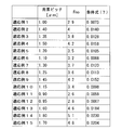
- conditional expression (7) may be satisfied. 2.5 ⁇ P ⁇ Fno ⁇ 0.03 (7)
- P is the pitch of the image sensor
- Fno is the effective F number of the objective optical system.
- the positioning accuracy can be improved even in an optical system that requires high-accuracy alignment that satisfies the conditional expression (7).
- the present invention it is possible to suppress the manufacturing error and improve the positioning accuracy between the image sensor and the objective lens.
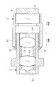
- an imaging unit for an endoscope according to this embodiment includes an objective lens unit frame 2 that holds an objective lens, and an imaging element holding frame that fits the objective lens unit frame 2 and holds the imaging element. 3 is provided.
- the objective lens unit frame 2 is on the inner side and the image sensor holding frame 3 is on the outer side when fitted.
- the objective lens unit frame 2 holds a plurality of lenses L1, L2, L3, and L4.
- the objective lens unit frame 2 has a fitting portion 10 at which the end on the imaging surface side is fitted with the imaging element holding frame 3.
- the image sensor holding frame 3 holds the image sensor 4 and the cover glass 5.
- the image sensor holding frame 3 has a fitting portion 11 whose end on the object plane side is fitted with the objective lens unit frame 2.
- the outer surface other than is configured to satisfy the following conditional expression.
- (alpha) is the infrared absorption factor per unit area of the outer surface of the said fitting part
- (beta) is the infrared absorption factor per unit area of outer surfaces other than the said fitting part.
- the image pickup device holding frame 3 is made of a metal material, and the outer surface of the fitting portion 11 among the outer surfaces of the image pickup device holding frame 3 is chrome plated.
- the outer surface is not plated or the like, and has a glossy metal surface with an exposed surface processed with a metal material. That is, since the outer surface of the fitting part 11 is chrome-plated and black compared with the metal surface of the outer surface other than the fitting part 11 among the outer surfaces of the image sensor holding frame 3, infrared rays are efficiently used. Absorb.
- the outer surface of the fitting portion is shown as “ ⁇ portion” and the outer surface other than the fitting portion is shown as “ ⁇ portion” in FIG.
- the outer surface (metal surface) other than the fitting portion 11 that is not plated is used.
- the infrared absorption rate per unit area is about 7%.
- the outer surface of the fitting portion 11 in which chromium is plated on stainless steel can improve the infrared absorption rate per unit area to about 16% due to the effect of the chromium oxide film used for chromium plating. .
- conditional expression (2) instead of the conditional expression (1), the infrared absorption rate per unit area on the outer surface of the fitting portion 11 can be further improved. ⁇ / ⁇ > 4 (2)
- the endoscope imaging unit configured in this way is assembled as follows. That is, as shown in FIG. 2, an adhesive 12 made of a thermosetting resin is applied to the outer surface of the fitting portion 10 or the inner surface of the fitting portion 11, and the objective lens unit frame 2 and the image sensor holding frame 3 After adjusting the interval, the adhesive 12 is heated and cured using infrared rays from the outside.
- FIG. 2 only one infrared lamp is illustrated in a simplified manner. However, since it is actually necessary to heat the entire fitting portion, a plurality of infrared lamps are arranged on the circumference and heated.
- the outer surface of the fitting portion 11 in the imaging element holding frame 3 located on the outer side when fitting with the objective lens unit frame 2 is heated by infrared irradiation as compared with the portion other than the fitting portion 11. It is easy to be configured. For this reason, only the fitting part 11 can be efficiently heated by the infrared irradiation with respect to the fitting part 11, the positional deviation resulting from the thermal expansion of a jig or a part can be suppressed, and a manufacturing error can be suppressed. The positioning accuracy between the objective lens and the image sensor can be improved.
- the imaging element holding frame 3 located outside is made of a metal material, and chrome plating is applied to the metal material.
- chrome plating is applied to the metal material.
- other black treatments may be used, for example, chromate treatment, anodizing, etc. Processing, nickel plating, etc. may be used.
- Any of the imaging element holding frame 3 and the objective lens unit frame 2 that can be plated black in relation to the metal material applied to the outer frame can be applied.
- stainless steel is shown as the metal material, it is not limited to stainless steel, and metal materials such as copper, brass, aluminum, and iron can also be applied.
- the objective lens unit frame 2 when the objective lens unit frame 2 and the image sensor holding frame 3 are fitted together, the objective lens unit frame 2 is configured to be inside, and the image sensor holding frame 3 is configured to be outside. It is not limited to this.
- the objective lens unit frame 2 can be configured to be on the outside, and the image sensor holding frame 3 can be configured to be on the inside. In this case, the outside of the fitting portion 10 of the objective lens unit frame 2 that is on the outside when fitted.
- the infrared absorption rate is increased by applying chrome plating or the like to the surface.
- the outer surface of the fitting portion 11 of the imaging element holding frame 3 is subjected to chromium plating.
- an infrared ray is applied to the outer surface of the fitting portion 11. It can also be set as the structure which apply
- an infrared absorbing material is applied to the outer surface of the fitting portion in the frame located outside when the objective lens unit and the image sensor unit are fitted, and the conditional expression (1) is satisfied.
- it can be set as the structure where the outer surface of a fitting part is easy to be heated by infrared irradiation compared with outer surfaces other than a fitting part.
- the infrared absorbing material for example, a black paint or a black paint mixed with a metal oxide or the like so as to efficiently absorb infrared rays can be applied.
- a single black ink may be used, and the infrared absorption rate per unit area can be further increased by mixing metal oxide powders such as chromium, copper, iron, nickel, and molybdenum in order to further improve the absorption rate.
- Such paint is applied only to the outer surface of the fitting portion of the frame located outside, and the outer surface other than the fitting portion is a metal surface, so that the infrared absorption rate of the fitting portion is other than the fitting portion. It can be increased compared to the part.
- the surface roughness of the outer surface of the fitting portion 11 is the surface roughness of the outer surface other than the fitting portion.
- the portion indicated by the Ra portion in FIG. 3 is a rough surface. That is, the outer surface of the fitting portion 11 and the fitting portion 11 among the outer surfaces of the imaging device holding frame 3 which is a frame located outside when the objective lens unit frame 2 and the imaging device holding frame 3 are fitted.
- Other outer surfaces satisfy the above-described conditional expression (1) and the following conditional expression (3).
- Ra is the maximum height of the surface roughness of the outer surface of the fitting part 11
- Rb is the maximum height of the surface roughness of the outer surface other than the fitting part 11.
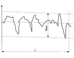
- the maximum height is a value ( ⁇ m) indicating a difference between the maximum value and the minimum value in the surface roughness, and when the surface roughness is measured in a certain reference range L as shown in FIG.
- the maximum value of the difference between the maximum height and the minimum height is expressed in ⁇ m.
- the outer surface of the fitting part 11 showing the maximum height Ra of the surface roughness is shown as Ra part, and the outer surface other than the fitting part 11 showing the maximum height Rb of the surface roughness is shown as Rb part. ing.
- the outer surface of the fitting portion 11 and the fitting portion at the stage of processing the frame.
- This can be realized by changing the rotational speed and feed amount of the cutting tool with an outer surface other than 11 or by sandblasting after machining.
- black processing such as plating, an imaging element holding frame in which the outer surface of the fitting portion 11 has a higher infrared absorption rate than the outer surface other than the fitting portion 11 can be configured.
- Ra 3.97 ⁇ Rb, which satisfies the condition of Ra> 3 ⁇ Rb.
- the endoscope imaging unit configured in this manner applies the adhesive 12 made of a thermosetting resin to the outer surface of the fitting portion 10 or the inner surface of the fitting portion 11, and images the objective lens unit frame 2 and the imaging unit. After adjusting the distance from the element holding frame 3, the adhesive 12 is heated and cured from outside using infrared rays.
- the surface roughness of the outer surface of the fitting portion 11 in the imaging element holding frame 3 positioned outside when fitting with the objective lens unit frame 2 is larger than that of the outer surface other than the fitting portion 11. It has a rough structure. For this reason, only the fitting part 11 can be efficiently heated by the infrared irradiation with respect to the fitting part 11, the positional deviation resulting from the thermal expansion of a jig or a part can be suppressed, and a manufacturing error can be suppressed. The positioning accuracy between the objective lens and the image sensor can be improved.
- the infrared absorptance ⁇ of the outer surface of the image sensor holding frame 3 positioned on the outer side during fitting is the outer surface of the objective lens unit frame 2 positioned on the inner side during fitting. It is configured to be higher than the infrared absorption rate ⁇ of the outer surface other than the fitting portion 10.
- the outer surface of the fitting portion 11 of the imaging element holding frame 3 showing the infrared absorption rate ⁇ is shown as ⁇ portion
- the outer surface other than the fitting portion 10 of the objective lens unit frame 2 showing the infrared absorption rate ⁇ It is shown as ⁇ part.
- ⁇ is the infrared absorption rate per unit area of the outer surface of the frame located on the outer side
- ⁇ is the infrared absorption rate per unit area of the outer surface other than the fitting portion of the outer surface of the frame located on the inner side. It is.
- ⁇ is the infrared absorption rate per unit area of the outer surface other than the fitting portion of the outer surface of the frame located on the inner side at the time of fitting.
- the entire outer surface including the fitting portion may have the same infrared absorption rate ⁇ . This means that in the case of irradiating infrared rays from the outside, the infrared rays do not hit the outer surface of the fitting portion of the frame located on the inner side during fitting, and either may be used.
- the imaging element holding frame 3 located on the outside and the objective lens unit frame 2 located on the inside are made of a metal material.
- stainless steel is used as the metal material, and the outer surface other than the fitting portion of the objective lens unit frame 2 on the inner side is exposed to the surface processed with the metal material without performing a treatment such as plating.
- the glossy metal surface can be used, and the outer surface of the fitting portion of the image sensor holding frame 3 on the outside can be plated with chromium.
- the outer peripheral surface of the fitting surface of the objective lens unit frame 2 located on the inner side is processed with a metal material without being subjected to a treatment such as plating similarly to the outer peripheral surface other than the fitting portion.
- the exposed surface becomes an exposed glossy metal surface.
- the imaging element holding frame 3 positioned outside is made of a metal material, and chrome plating is applied to the metal material.
- chrome plating is applied to the metal material.
- other black treatments may be used, for example, chromate treatment, anodizing, etc. Processing, nickel plating, etc. may be used.
- metal materials such as not only this but copper, brass, aluminum, iron, can also be applied.
- an infrared absorbing material may be applied. Examples of the infrared absorbing material are as described above.
- the surface roughness of the outer surface of the image sensor holding frame 3 positioned on the outer side during fitting is set to the outer surface other than the fitting portion 10 of the objective lens unit frame 2 positioned on the inner side. Make it rough.
- the outer surface of the image sensor holding frame 3 that is a frame located on the outer side and the objective lens unit frame 2 that is a frame located on the inner side satisfies the above-described conditional expression (4) and satisfies the following conditional expression (6).
- Rai is the maximum height of the surface roughness of the outer surface other than the fitting portion in the outer surface of the frame located on the inner side
- Rbo is the maximum height of the surface roughness of the outer surface of the frame located on the outer side. It is.
- the maximum height is a value ( ⁇ m) indicating a difference between the maximum value and the minimum value of the surface roughness.
- Rai is the maximum height of the surface roughness of the outer surface other than the fitting portion 10 among the outer surfaces of the inner frame, but the entire outer surface including the fitting portion of the inner frame. May have the same surface roughness Rai.
- the infrared rays do not hit the outer surface of the fitting portion of the frame located on the inner side during fitting, and either may be used.
- the outer surface other than the fitting portion 10 of the objective lens unit frame 2 showing the maximum height Rai of the surface roughness is shown as a Rai portion, and the imaging element holding frame 3 showing the maximum height Rbo of the surface roughness.
- the outer surface is shown as the Rbo part.
- the outer surface of the objective lens unit frame 2 positioned on the inner side is the outer surface other than the fitting portion 10.
- both the objective lens unit frame 2 and the image sensor holding frame 3 are made of a stainless material, and at least the outer surface is subjected to black plating.
- the infrared absorptance per unit area of the outer surface of the objective lens unit frame 2 positioned inside in the fitting portion, and the infrared absorptivity per unit area of the outer surface of the image sensor holding frame 3 positioned outside The ratio is ⁇ / ⁇ 1.81 times.
- the above conditional expression (6) is satisfied, and in this case, ⁇ / ⁇ is 2.4 times.
- the surface roughness of the outer peripheral surface of the fitting portion of the objective lens unit frame 2 located inside the fitting portion is the same as the surface roughness Rai of the outer peripheral surface other than the fitting portion. May be different.
- the black plating on the metal can be appropriately selected from chrome plating, chromate treatment, alumite treatment, nickel plating, and the like that can be processed black due to the relationship with the metal material.
- the objective lens holding frame 2 and the image sensor holding frame 3 are not limited to stainless steel, and various metal materials such as copper, brass, aluminum, and iron can be applied.
- An image sensor that uses a luminance signal is an example of an image sensor that uses such a reference amount.
- FIG. 8 lists application examples 1 to 15 as examples of optical systems that require highly accurate alignment that satisfies the conditional expression (7).
Abstract
Priority Applications (4)
| Application Number | Priority Date | Filing Date | Title |
|---|---|---|---|
| CN201580001659.1A CN105473050B (zh) | 2014-03-28 | 2015-02-03 | 内窥镜用摄像单元 |
| EP15768959.7A EP3123920A4 (fr) | 2014-03-28 | 2015-02-03 | Unité d'imagerie pour endoscopes |
| JP2015546762A JP5851668B1 (ja) | 2014-03-28 | 2015-02-03 | 内視鏡用撮像ユニット |
| US15/050,763 US20160166132A1 (en) | 2014-03-28 | 2016-02-23 | Endoscopic Image-Acquisition Unit |
Applications Claiming Priority (2)
| Application Number | Priority Date | Filing Date | Title |
|---|---|---|---|
| JP2014068942 | 2014-03-28 | ||
| JP2014-068942 | 2014-03-28 |
Related Child Applications (1)
| Application Number | Title | Priority Date | Filing Date |
|---|---|---|---|
| US15/050,763 Continuation US20160166132A1 (en) | 2014-03-28 | 2016-02-23 | Endoscopic Image-Acquisition Unit |
Publications (1)
| Publication Number | Publication Date |
|---|---|
| WO2015146290A1 true WO2015146290A1 (fr) | 2015-10-01 |
Family
ID=54194830
Family Applications (1)
| Application Number | Title | Priority Date | Filing Date |
|---|---|---|---|
| PCT/JP2015/052962 WO2015146290A1 (fr) | 2014-03-28 | 2015-02-03 | Unité d'imagerie pour endoscopes |
Country Status (5)
| Country | Link |
|---|---|
| US (1) | US20160166132A1 (fr) |
| EP (1) | EP3123920A4 (fr) |
| JP (1) | JP5851668B1 (fr) |
| CN (1) | CN105473050B (fr) |
| WO (1) | WO2015146290A1 (fr) |
Families Citing this family (3)
| Publication number | Priority date | Publication date | Assignee | Title |
|---|---|---|---|---|
| JP2017185086A (ja) * | 2016-04-07 | 2017-10-12 | オリンパス株式会社 | 医療機器および医療機器用熱硬化型接着剤 |
| US11931010B2 (en) | 2017-03-24 | 2024-03-19 | Covidien Lp | Endoscopes and methods of treatment |
| WO2018216300A1 (fr) * | 2017-05-26 | 2018-11-29 | オリンパス株式会社 | Unité optique |
Citations (3)
| Publication number | Priority date | Publication date | Assignee | Title |
|---|---|---|---|---|
| JPH09192093A (ja) * | 1996-01-23 | 1997-07-29 | Olympus Optical Co Ltd | 撮像装置 |
| JP2008125902A (ja) * | 2006-11-22 | 2008-06-05 | Pentax Corp | 内視鏡スコープおよび内視鏡スコープの製造方法 |
| WO2011092904A1 (fr) * | 2010-02-01 | 2011-08-04 | オリンパスメディカルシステムズ株式会社 | Structure pour extrémité d'endoscope |
Family Cites Families (9)
| Publication number | Priority date | Publication date | Assignee | Title |
|---|---|---|---|---|
| US5305736A (en) * | 1991-04-26 | 1994-04-26 | Asahi Kogaku Kogyo Kabushiki Kaisha | Distal end part of endoscope |
| EP0978251B1 (fr) * | 1998-08-07 | 2005-01-26 | Olympus Corporation | Endoscope pouvant être passé à l'autoclave |
| JP3297033B2 (ja) * | 2000-02-02 | 2002-07-02 | オリンパス光学工業株式会社 | 内視鏡 |
| JP2002336190A (ja) * | 2001-03-12 | 2002-11-26 | Olympus Optical Co Ltd | 内視鏡 |
| US6936735B2 (en) * | 2002-08-27 | 2005-08-30 | Emd Chemicals, Inc. | Photostable cationic organic sunscreen compounds and compositions obtained therefrom |
| JP3967337B2 (ja) * | 2004-05-14 | 2007-08-29 | オリンパス株式会社 | 内視鏡および内視鏡装置 |
| JP4864624B2 (ja) * | 2006-09-28 | 2012-02-01 | Hoya株式会社 | 電子内視鏡の先端光学ユニット |
| JP2008018254A (ja) * | 2007-08-21 | 2008-01-31 | Olympus Corp | カプセル型内視鏡 |
| JP2010269072A (ja) * | 2009-05-25 | 2010-12-02 | Hoya Corp | 固体撮像装置及びその製造方法 |
-
2015
- 2015-02-03 WO PCT/JP2015/052962 patent/WO2015146290A1/fr active Application Filing
- 2015-02-03 EP EP15768959.7A patent/EP3123920A4/fr not_active Withdrawn
- 2015-02-03 CN CN201580001659.1A patent/CN105473050B/zh not_active Expired - Fee Related
- 2015-02-03 JP JP2015546762A patent/JP5851668B1/ja active Active
-
2016
- 2016-02-23 US US15/050,763 patent/US20160166132A1/en not_active Abandoned
Patent Citations (3)
| Publication number | Priority date | Publication date | Assignee | Title |
|---|---|---|---|---|
| JPH09192093A (ja) * | 1996-01-23 | 1997-07-29 | Olympus Optical Co Ltd | 撮像装置 |
| JP2008125902A (ja) * | 2006-11-22 | 2008-06-05 | Pentax Corp | 内視鏡スコープおよび内視鏡スコープの製造方法 |
| WO2011092904A1 (fr) * | 2010-02-01 | 2011-08-04 | オリンパスメディカルシステムズ株式会社 | Structure pour extrémité d'endoscope |
Non-Patent Citations (1)
| Title |
|---|
| See also references of EP3123920A4 * |
Also Published As
| Publication number | Publication date |
|---|---|
| JPWO2015146290A1 (ja) | 2017-04-13 |
| EP3123920A4 (fr) | 2017-12-27 |
| US20160166132A1 (en) | 2016-06-16 |
| JP5851668B1 (ja) | 2016-02-03 |
| CN105473050B (zh) | 2017-11-07 |
| EP3123920A1 (fr) | 2017-02-01 |
| CN105473050A (zh) | 2016-04-06 |
Similar Documents
| Publication | Publication Date | Title |
|---|---|---|
| JP5853179B2 (ja) | 内視鏡及び内視鏡の製造方法 | |
| JP5851668B1 (ja) | 内視鏡用撮像ユニット | |
| JP5893801B2 (ja) | 撮像装置 | |
| JP5866565B1 (ja) | 内視鏡 | |
| JP2016184082A (ja) | レンズユニットおよびカメラモジュール | |
| JP5711438B1 (ja) | 内視鏡用撮像ユニット及び内視鏡装置 | |
| JP6675418B2 (ja) | 内視鏡用結像ユニット及び結像ユニットの製造方法 | |
| US9784964B2 (en) | Image pickup unit for endoscope having multiple bonded frames | |
| WO2017022500A1 (fr) | Procédé de fixation d'ensemble optique par adhérence et ensemble optique | |
| US8472797B2 (en) | Image capturing lens system | |
| JP2014033730A5 (fr) | ||
| JP5958727B2 (ja) | 内視鏡 | |
| JP6862146B2 (ja) | 光学機器 | |
| JP5914784B2 (ja) | 内視鏡用撮像装置及び内視鏡用撮像装置の組立方法 | |
| JP2016020951A (ja) | レンズ鏡筒および光学機器 | |
| JP2016116845A (ja) | レンズユニット及び内視鏡 | |
| US20150346454A1 (en) | Optical apparatus and image capturing apparatus | |
| JP2009244604A (ja) | カメラモジュールの組立装置 |
Legal Events
| Date | Code | Title | Description |
|---|---|---|---|
| WWE | Wipo information: entry into national phase |
Ref document number: 201580001659.1 Country of ref document: CN |
|
| ENP | Entry into the national phase |
Ref document number: 2015546762 Country of ref document: JP Kind code of ref document: A |
|
| 121 | Ep: the epo has been informed by wipo that ep was designated in this application |
Ref document number: 15768959 Country of ref document: EP Kind code of ref document: A1 |
|
| NENP | Non-entry into the national phase |
Ref country code: DE |
|
| REEP | Request for entry into the european phase |
Ref document number: 2015768959 Country of ref document: EP |
|
| WWE | Wipo information: entry into national phase |
Ref document number: 2015768959 Country of ref document: EP |