WO2015146239A1 - 圧縮装置および圧縮装置の制御方法 - Google Patents
圧縮装置および圧縮装置の制御方法 Download PDFInfo
- Publication number
- WO2015146239A1 WO2015146239A1 PCT/JP2015/051334 JP2015051334W WO2015146239A1 WO 2015146239 A1 WO2015146239 A1 WO 2015146239A1 JP 2015051334 W JP2015051334 W JP 2015051334W WO 2015146239 A1 WO2015146239 A1 WO 2015146239A1
- Authority
- WO
- WIPO (PCT)
- Prior art keywords
- pressure
- compressor
- tank
- follow
- compressors
- Prior art date
- Legal status (The legal status is an assumption and is not a legal conclusion. Google has not performed a legal analysis and makes no representation as to the accuracy of the status listed.)
- Ceased
Links
Images

Classifications
-
- F—MECHANICAL ENGINEERING; LIGHTING; HEATING; WEAPONS; BLASTING
- F04—POSITIVE - DISPLACEMENT MACHINES FOR LIQUIDS; PUMPS FOR LIQUIDS OR ELASTIC FLUIDS
- F04B—POSITIVE-DISPLACEMENT MACHINES FOR LIQUIDS; PUMPS
- F04B49/00—Control, e.g. of pump delivery, or pump pressure of, or safety measures for, machines, pumps, or pumping installations, not otherwise provided for, or of interest apart from, groups F04B1/00 - F04B47/00
- F04B49/06—Control using electricity
Definitions
- the present invention relates to a compression device for starting or stopping a plurality of compressors and a control method for the compression device.
- Compressor control device that starts or stops a plurality of compressors in sequence monitors the pressure of a tank that stores compressed air discharged from each compressor. When the tank pressure exceeds the upper limit pressure, the control device determines that supply is excessive and stops one compressor. On the other hand, an operation state in which the tank pressure is lower than the lower limit pressure is not preferable because there is a possibility that the tank may be lower than the minimum pressure required on the supply side. Therefore, if the pressure falls below the lower limit pressure, the control device determines that the supply is insufficient and starts one compressor.
- Patent Document 1 calculates a time td until the pressure in the tank reaches the lower limit pressure Pmin and a time tu until the pressure reaches the upper limit pressure Pmax.
- a control device for increasing or decreasing the number of operating machines is described. This control device keeps the pressure in the tank within a predetermined range by increasing the number of operating compressors when the time td is shortened and decreasing the number of operating compressors when the time tu is shortened.
- control by the control device of Patent Document 1 is performed every predetermined sampling period. Therefore, when the sampling period is set to be long, it is not possible to control the stop and start of the compressor at an appropriate timing.
- the present invention provides a compression device and a control method for the compression device that can additionally start the compressor at an appropriate timing.
- a compression apparatus includes a plurality of compressors that compress and discharge gas, a tank that stores compressed gas discharged and collected from the plurality of compressors, and a pressure detector that detects pressure in the tank. And a timing device that measures the time after stopping when at least one of the compressors is stopped, and the pressure in the tank is at a lower limit pressure when the at least one compressor is stopped. When at least one of the compressors is stopped, the at least one compressor is stopped in response to a change in pressure detected by the pressure detector, and then a desired compressor is additionally started among the stopped compressors.
- a control device that calculates a follow-up interval time, and causes the desired compressor to be additionally started when the time measured by the timing device passes the calculated follow-up interval time; Equipped with.
- the additional start is to stop the operation of at least one compressor and start the stopped compressor after a desired time has elapsed when the pressure in the tank becomes less than the lower limit pressure.
- the follow-up interval time is a time period from when at least one compressor is stopped until the next desired compressor is started.
- the compressor In the state where the pressure in the tank is less than the lower limit pressure, the compressor is further started based on the calculated subsequent start interval time, so that the compressor can be started at an appropriate timing according to the pressure change in the tank.
- the control device preferably shortens the follow-up activation time when the change in pressure is a negative change.
- the control device preferably lengthens the follow-up interval time when the change in pressure is a positive change.
- a plurality of compressors for compressing and discharging gas for compressing and discharging gas; a tank for storing compressed gas discharged and collected from the plurality of compressors; a pressure detector for detecting pressure in the tank; and the compressor And a timing device that measures a time after the stop when at least one compressor is stopped.
- the control method of the compressor includes: stopping the at least one compressor and stopping the pressure in the tank. When the pressure becomes lower than the lower limit pressure, a desired compressor is added to the stopped compressors after stopping the at least one compressor according to the change in pressure detected by the pressure detector. The additional start interval time to be started is calculated, and the desired compressor is additionally started when the time measured by the timing device exceeds the calculated additional start interval time.
- the compressor can be additionally started at an appropriate timing according to the pressure change in the tank.
- the timing for the follow-up of the compressor can be advanced, and the operation in a state where the pressure in the tank is less than the lower limit pressure can be shortened.
- the timing of the follow-up of the compressor can be delayed to prevent frequent follow-up of the compressor and reduce power consumption.
- the compression device and the control method for the compression device of the present invention in a state where the pressure in the tank is less than the lower limit pressure, the compression is performed at an appropriate timing according to the pressure change in the tank based on the calculated follow-up interval time. You can start the machine. In particular, by shortening the follow-up interval time, the timing at which the compressor is additionally started can be accelerated, and the operation in a state where the pressure in the tank is less than the lower limit pressure can be shortened.
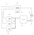
- the block diagram which shows schematic structure of the compression apparatus which concerns on embodiment of this invention.
- the characteristic diagram which shows the pressure in a tank, and the time change of the driving
- the compression apparatus 1 of the present embodiment includes three compressors 10A to 10C (compressor No. 10A, compressor No. 2B 10B, and compressor No. 3C 10C) that compress and discharge gas. These are hereinafter referred to as No. 1 machine 10A, No. 2 machine 10B, and No. 3 machine 10C) and a tank 14 for storing the compressed gas discharged and collected from the three compressors 10A to 10C.
- the stopped compressors 10A to 10C are started in the order of No. 1 unit 10A, No. 2 unit 10B, and No. 3 unit 10C, and the operating compressors 10A to 10C are stopped in the order of No. 1 unit 10A, No. 2 unit 10B, and No. 3 unit 10C.
- a valve 15 that supplies compressed gas in the tank 14 to a gas supply destination (not shown) and a pressure sensor (pressure detector) 16 that measures the pressure in the tank 14 are fluidly connected to the tank 14.
- a control device 20 and a timer (timer device) 21 are electrically connected via the control device 20.
- the control device 20 stops the operation of at least one of the compressors 10A to 10C, and when the pressure in the tank 14 becomes less than the lower limit pressure, according to the pressure change in the tank 14 detected by the pressure sensor 16, A follow-up interval time for further starting the compressor after the stop is calculated.
- the control device 20 also causes the compressor to be additionally activated when the time measured by the timer 21 exceeds the calculated additional activation interval time.
- the timer 21 measures the time after stopping when at least one of the operating compressors is stopped.
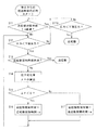
- step S ⁇ b> 11 the control device 20 determines whether or not the elapsed time measured by the timer 21 has passed a predetermined follow-up interval time Tin. If it has elapsed, the process proceeds to step S11A, and the control device 20 determines whether or not the pressure in the tank 14 measured by the pressure sensor 16 is less than the lower limit pressure.
- the state below the lower limit pressure is a pressure state in each of the regions B1 to B3 and C1 to C3 in FIG. If the pressure in the tank 14 is not less than the lower limit pressure, the process returns to step S11. If it is less than the lower limit pressure, the first machine 10A is additionally started. On the other hand, if the additional activation interval time Tin has not elapsed in step S11, the process proceeds to step S12.
- step S12 the control device 20 determines whether or not the pressure in the tank 14 measured by the pressure sensor 16 is less than the lower limit pressure. If the pressure in the tank 14 is not less than the lower limit pressure, the process returns to step S11. If it is less than the lower limit pressure, the process proceeds to step S13.
- step S13 the control device 20 determines whether or not the elapsed time measured by the timer 21 has passed the subsequent startup interval time (current set value). If it has elapsed, the first machine 10A is additionally activated. If not, the process proceeds to step S14.
- step S13 the additional activation interval time Tin (initial value) is used for determination until the set value of the additional activation interval time is updated from the predetermined additional activation interval time Tin (initial value).
- the subsequent startup interval time (current set value) set at that time is used for determination in step S13 every time the additional startup interval time described later is calculated until the elapsed time has elapsed. Update the set value of the follow-up interval time.
- step S14 the control device 20 calculates the pressure change amount ⁇ P obtained by dividing the difference between the current pressure P (t) and the previous pressure P (t ⁇ 1) by the unit time ⁇ T. Is calculated.
- step S15 the control device 20 determines whether or not the pressure change amount ⁇ P is smaller than zero.
- the state in which the pressure change amount ⁇ P is smaller than 0 means that the pressure changes so as to decrease, and a negative pressure change occurs, and the slope of the graph G becomes negative as in each of the areas B1, B2, and B3 in FIG. That is. If the pressure change amount ⁇ P is smaller than 0, the process proceeds to step S16.
- step S16 the control device 20 changes the follow-up interval time used in the next flow to a value obtained by subtracting the constant ⁇ from the follow-up interval time set at that time. In this manner, the control device 20 calculates the follow-up activation time and updates the set value. Then, the process returns to step S12.
- step S15 If the pressure change amount ⁇ P is not smaller than 0 in step S15, the process proceeds to step S17.
- the state in which the pressure change amount ⁇ P is not smaller than 0 means that the pressure increases so that a positive pressure change occurs, and the slope of the graph G becomes positive as in the areas C1, C2, and C3 in FIG. It is to become.
- step S17 the control device 20 changes the follow-up interval time used in the next flow to a value obtained by adding the constant ⁇ to the follow-up interval time set at that time. In this manner, the control device 20 calculates the follow-up activation time and updates the set value. Then, the process returns to step S12.
- Step S16 returns to Step S12, and if the pressure in the tank 14 is less than the lower limit pressure, the process proceeds to Step S13.
- the follow-up interval time used in step S13 is the follow-up interval time changed and shortened in step S16 of the flow before returning to step S12. And it is judged whether the elapsed time measured by the timer 21 has passed the shortened follow-up interval time, and if it has passed, the first machine 10A is further started.
- step S13 the follow-up interval time used in step S13 is the follow-up interval time changed and lengthened in step S17 of the flow before returning to step S12. Then, it is determined whether or not the elapsed time measured by the timer 21 has passed the extended follow-up interval time, and if it has elapsed, the first machine 10A is further started. By extending the follow-up interval time in this way, the timing at which the first machine 10A is additionally started can be delayed, and frequent follow-up of the compressors 10A to 10C can be prevented to reduce power consumption.
- step S13 if the elapsed time measured by the timer 21 does not exceed the current follow-up interval time (current set value), the process proceeds to step S14 and step S15. If it is determined in step S15 that the pressure change amount ⁇ P is smaller than 0, the process proceeds to step S16. In step S16, the control device 20 changes the follow-up interval time used in the next flow to a value obtained by subtracting the constant ⁇ from the current follow-up interval time. Then, the process returns to step S12 and the flow is repeated until the first car 10A is additionally started. If it is determined in step S15 that the pressure change amount ⁇ P is not smaller than 0, the process proceeds to step S17.
- step S17 the control device 20 changes the follow-up activation time used in the next flow to a value obtained by adding the constant ⁇ to the current follow-up activation time. Then, the process returns to step S12 and the flow is repeated until the first car 10A is additionally started.
- the pressure in the tank 14 rises and exceeds the lower limit pressure at point E as shown by the graph G1.
- the graph G2 shows the pressure change due to the follow-up control of the conventional compressor.
- the follow-up interval time is not shortened according to the pressure change in the tank 14 and the compressor is additionally started at a predetermined F point.
- the follow-up activation time is shortened according to the pressure change in the tank 14.
- the No. 1 machine 10A is additionally started based on the calculated additional start interval time, so at an appropriate timing according to the pressure change in the tank 14.
- the first machine 10A can be additionally started.
- the follow-up interval time for starting the first unit 10A is calculated.
- the order of the first machine 10A, the second machine 10B, and the third machine 10C is performed in order to prevent the operation frequency of the compressors 10A to 10C from being biased. If it follows, it will not specifically limit.
- the first unit 10A is started from a state where the three compressors 10A to 10C are stopped. After that, even if the No. 1 machine 10A is stopped and the subsequent startup interval time for the subsequent startup of the No. 2 machine 10B is calculated, the same operation and effect as in the above embodiment can be obtained.
- the first machine 10A and the second machine 10B are started in order. Thereafter, the No. 1 machine 10A may be stopped, and then the follow-up interval time for further starting the No. 3 machine 10C may be calculated.
- the first machine 10A, the second machine 10B, and the third machine 10C are started in order. Thereafter, the No. 1 machine 10A and the No. 2 machine 10B may be stopped, and the follow-up interval time for the subsequent start-up of the No. 1 machine 10A and the No. 2 machine may be calculated.
Landscapes
- Engineering & Computer Science (AREA)
- Mechanical Engineering (AREA)
- General Engineering & Computer Science (AREA)
- Control Of Positive-Displacement Pumps (AREA)
Abstract
圧縮装置は、ガスを圧縮して吐出する複数の圧縮機(10A~10C)、複数の圧縮機(10A~10C)から吐出され集められた圧縮ガスを貯留するタンク(14)、タンク(14)内の圧力を検出する圧力検出器(16)、計時装置(21)、および制御装置(20)を備える。計時装置(21)は、圧縮機(10A~10C)を停止したときに、停止してからの時間を計測する。制御装置(20)は、圧縮機(10A~10C)のうち少なくとも1台を停止しタンク(14)内の圧力が下限圧力未満になったとき、圧力検出器(16)により検出された圧力の変化に応じて、停止中の所望の圧縮機(10A~10C)を追起動させる追起動間隔時間を演算する。制御装置(20)は、計時装置(21)により計測された時間が、演算された追起動間隔時間を経過すると所望の圧縮機(10A~10C)を追起動させる。
Description
本発明は、複数台の圧縮機を起動または停止させる圧縮装置および圧縮装置の制御方法に関する。
複数の圧縮機を順に起動または停止させる圧縮装置の制御装置は、各圧縮機から吐出された圧縮空気を貯留するタンクの圧力を監視する。そして制御装置は、タンクの圧力が上限圧力を超えると供給過剰と判断して1台の圧縮機を停止させる。一方、タンクの圧力が下限圧力未満となる運転状態は、供給側が必要とする最低圧力を下回る恐れがあるため好ましくない。従って、下限圧力を下回ると、制御装置は供給不足と判断し1台の圧縮機を起動させる。
このような圧縮装置の制御装置として例えば、特許文献1には、タンク内の圧力が下限圧力Pminに到達するまでの時間td、および上限圧力Pmaxに到達するまでの時間tuを演算して、圧縮機の運転台数を増減させる制御装置が記載されている。この制御装置は、時間tdが短くなれば圧縮機の運転台数を増やし、時間tuが短くなれば圧縮機の運転台数を減らすことで、タンク内の圧力を所定の範囲内に抑えている。
しかし、特許文献1の制御装置による制御は、予め決められたサンプリング周期毎に行われる。従って、サンプリング周期が長く設定された場合には、適切なタイミングで圧縮機の停止および起動の制御を行うことができない。
本発明は、適切なタイミングで圧縮機を追起動できる圧縮装置および圧縮装置の制御方法を提供する。
本発明の圧縮装置は、ガスを圧縮して吐出する複数の圧縮機と、前記複数の圧縮機から吐出され集められた圧縮ガスを貯留するタンクと、前記タンク内の圧力を検出する圧力検出器と、前記圧縮機のうち少なくとも1台の圧縮機を停止したときに、停止してからの時間を計測する計時装置と、前記少なくとも1台の圧縮機を停止し前記タンク内の圧力が下限圧力未満になったとき、前記圧力検出器により検出された圧力の変化に応じて、前記少なくとも1台の圧縮機を停止してから、停止中の圧縮機の中で所望の圧縮機を追起動させる追起動間隔時間を演算し、前記計時装置により計測された時間が、演算された前記追起動間隔時間を経過すると前記所望の圧縮機を追起動させる制御装置と、
を備えた。
を備えた。
ここで追起動とは、少なくとも1台の圧縮機の運転を停止し、タンク内の圧力が下限圧力未満の状態になると所望の時間経過後に停止中の圧縮機を起動させることである。また、追起動間隔時間とは、少なくとも1台の圧縮機を停止してから次に所望の圧縮機を起動させるまでの間の時間のことである。
タンク内の圧力が下限圧力未満となる状態において、演算された追起動間隔時間に基づき圧縮機を追起動させるので、タンク内の圧力変化に応じて適切なタイミングで圧縮機を追起動できる。
前記制御装置は、前記圧力の変化が負の変化であるとき、前記追起動間隔時間を短くすることが好ましい。
追起動間隔時間を短くすることで圧縮機が追起動するタイミングを早くし、タンク内の圧力が下限圧力未満となる状態での運転を短縮できる。
前記制御装置は、前記圧力の変化が正の変化であるとき、前記追起動間隔時間を長くすることが好ましい。
追起動間隔時間を長くすることで圧縮機が追起動するタイミングを遅くし、圧縮機の頻繁な追起動を防止して消費電力を抑制できる。
ガスを圧縮して吐出する複数の圧縮機と、前記複数の圧縮機から吐出され集められた圧縮ガスを貯留するタンクと、前記タンク内の圧力を検出する圧力検出器と、前記圧縮機のうち少なくとも1台の圧縮機を停止したときに、停止してからの時間を計測する計時装置と、を備えた圧縮装置の制御方法は、前記少なくとも1台の圧縮機を停止し前記タンク内の圧力が下限圧力未満になったとき、前記圧力検出器により検出された圧力の変化に応じて、前記少なくとも1台の圧縮機を停止してから停止中の圧縮機の中で所望の圧縮機を追起動させる追起動間隔時間を演算し、前記計時装置により計測された時間が、演算された前記追起動間隔時間を経過すると前記所望の圧縮機を追起動させる。
演算された追起動間隔時間に基づいて圧縮機を追起動させるので、タンク内の圧力変化に応じて適切なタイミングで圧縮機を追起動できる。負の圧力変化が生じて追起動間隔時間が短くなる場合には、圧縮機が追起動するタイミングを早くし、タンク内の圧力が下限圧力未満となる状態での運転を短縮できる。正の圧力変化が生じて追起動間隔時間が長くなる場合には、圧縮機が追起動するタイミングを遅くし、圧縮機の頻繁な追起動を防止して消費電力を抑制できる。
本発明の圧縮装置および圧縮装置の制御方法によれば、タンク内の圧力が下限圧力未満となる状態において、演算された追起動間隔時間に基づきタンク内の圧力変化に応じて適切なタイミングで圧縮機を追起動できる。特に、追起動間隔時間を短くすることで圧縮機が追起動するタイミングを早くし、タンク内の圧力が下限圧力未満となる状態での運転を短縮できる。
以下、本発明の実施形態を添付図面に従って説明する。
図1に示すように、本実施形態の圧縮装置1は、ガスを圧縮して吐出する3台の圧縮機10A~10C(圧縮機1号機10A、圧縮機2号機10B、および圧縮機3号機10C、以下それぞれを1号機10A、2号機10B、3号機10Cと呼ぶ)と、3台の圧縮機10A~10Cから吐出され集められた圧縮ガスを貯留するタンク14とを備えている。停止中の圧縮機10A~10Cは1号機10A、2号機10B、3号機10Cの順に起動され、運転中の圧縮機10A~10Cは1号機10A、2号機10B、3号機10Cの順に停止される。タンク14には、タンク14内の圧縮ガスを図示しないガス供給先に供給するバルブ15と、タンク14内の圧力を測定する圧力センサ(圧力検出器)16とが流体的に接続されている。
圧縮機10A~10Cと圧力センサ16との間には、制御装置20と、制御装置20を介してタイマ(計時装置)21とが電気的に接続されている。制御装置20は、少なくとも1台の圧縮機10A~10Cの運転を停止しタンク14内の圧力が下限圧力未満になったとき、圧力センサ16により検出されたタンク14内の圧力変化に応じて、停止してから圧縮機を追起動させる追起動間隔時間を演算する。制御装置20はまた、タイマ21により計測された時間が、演算された前記追起動間隔時間を経過すると圧縮機を追起動させる。タイマ21は、運転中の圧縮機のうち少なくとも1台を停止したときに、停止してからの時間を計測する。
次に、タンク14内の圧力に応じて圧縮機10A~10Cを運転または停止させる制御方法について説明する。
全ての圧縮機10A~10Cが運転している状態で、タンク14内の圧力が上限圧力を超えたA点(図3参照)で1号機10Aの運転を停止させる。このとき図2に示すフローチャートのように、タイマ21により、運転を停止してからの経過時間の計測をスタートする。ステップS11において制御装置20は、タイマ21により計測された経過時間が、予め決められた追起動間隔時間Tinを経過したか否かを判断する。経過していればステップS11Aに進み、制御装置20は、圧力センサ16により測定されたタンク14内の圧力が下限圧力未満であるか否かを判断する。下限圧力未満の状態とは、図3におけるB1からB3およびC1からC3の各領域における圧力状態である。タンク14内の圧力が下限圧力未満でなければステップS11に戻る。下限圧力未満であれば、1号機10Aを追起動させる。一方、ステップS11において、追起動間隔時間Tinが経過していなければ、ステップS12に進む。
ステップS12において制御装置20は、圧力センサ16により測定されたタンク14内の圧力が下限圧力未満であるか否かを判断する。タンク14内の圧力が下限圧力未満でなければステップS11に戻る。下限圧力未満であれば、ステップS13に進む。
ステップS13において制御装置20は、タイマ21により計測された経過時間が、その時設定されている追起動間隔時間(現在の設定値)を経過したか否かを判断する。経過していれば1号機10Aを追起動させる。経過していなければ、ステップS14に進む。なお、ステップS13では、追起動間隔時間の設定値が予め決められた追起動間隔時間Tin(初期値)から更新されるまでは、追起動間隔時間Tin(初期値)を判断に用いる。初期値から更新されて以降、その時設定されている追起動間隔時間(現在の設定値)を経過時間が経過するまでは、後述する追起動間隔時間の演算の都度、ステップS13での判断に用いる追起動間隔時間の設定値を更新する。
ステップS14では制御装置20が、以下の数1の式に示すように、現在の圧力P(t)と前回の圧力P(t-1)との差を単位時間ΔTで割った圧力変化量ΔPを演算する。

この後、ステップS15に進み、制御装置20が圧力変化量ΔPは0よりも小さいか否かを判断する。圧力変化量ΔPが0よりも小さい状態とは、圧力が低下するよう変化し負の圧力変化が生じて、図3のB1,B2およびB3の各領域のようにグラフGの傾きがマイナスになることである。圧力変化量ΔPが0よりも小さければステップS16に進む。ステップS16では制御装置20が、次のフローで使用する追起動間隔時間を、その時設定されている追起動間隔時間から定数αを引いた値に変更する。このように、制御装置20において追起動間隔時間を演算し、その設定値を更新する。そしてステップS12に戻る。
ステップS15で圧力変化量ΔPが0よりも小さくなければ、ステップS17に進む。圧力変化量ΔPが0よりも小さくない状態とは、圧力が上昇するよう変化し正の圧力変化が生じて、図3のC1,C2およびC3の各領域のようにグラフGの傾きがプラスになることである。ステップS17では制御装置20が、次のフローで使用する追起動間隔時間を、その時設定されている追起動間隔時間に定数αを足した値に変更する。このように、制御装置20において追起動間隔時間を演算し、その設定値を更新する。そしてステップS12に戻る。
ステップS16からステップS12に戻り、タンク14内の圧力が下限圧力未満であればステップS13に進む。このとき、ステップS13で用いる追起動間隔時間は、ステップS12に戻る前のフローのステップS16で変更され短くされた追起動間隔時間となる。そして、タイマ21により計測された経過時間が、短くされた追起動間隔時間を経過したか否かを判断し、経過していれば1号機10Aを追起動させる。
ステップS17からステップS12に戻り、タンク14内の圧力が下限圧力未満であればステップS13に進む。このとき、ステップS13で用いる追起動間隔時間は、ステップS12に戻る前のフローのステップS17で変更され長くされた追起動間隔時間となる。そして、タイマ21により計測された経過時間が、長くされた追起動間隔時間を経過したか否かを判断し、経過していれば1号機10Aを追起動させる。このように追起動間隔時間を長くすることで、1号機10Aが追起動するタイミングを遅くし、圧縮機10A~10Cの頻繁な追起動を防止して消費電力を抑制できる。
ステップS13で、タイマ21により計測された経過時間が、現在の追起動間隔時間(現在の設定値)を経過していなければステップS14およびステップS15に進む。ステップS15で圧力変化量ΔPが0よりも小さいと判断されればステップS16に進む。ステップS16では制御装置20が、次のフローで使用する追起動間隔時間を、現在の追起動間隔時間から定数αを引いた値に変更する。そしてステップS12に戻り、1号機10Aが追起動するまでフローを繰り返す。ステップS15で圧力変化量ΔPが0よりも小さくないと判断されればステップS17に進む。ステップS17では制御装置20が、次のフローで使用する追起動間隔時間を、現在の追起動間隔時間から定数αを足した値に変更する。そしてステップS12に戻り、1号機10Aが追起動するまでフローを繰り返す。
上述のフローを繰り返し、例えば図3のD点で1号機10Aを追起動させると、グラフG1で示すように、タンク14内の圧力が上昇しE点で下限圧力を上回る。なお、グラフG2は、従来の圧縮機の追起動制御による圧力変化を示す。従来の追起動制御では、タンク14内の圧力変化に応じて追起動間隔時間を短くすることはなく、予め決められたF点で圧縮機を追起動させる。これに対し本願発明では、タンク14内の圧力変化に応じて追起動間隔時間を短くする。これにより、1号機10Aが追起動するタイミングを早くし、タンク14内の圧力が下限圧力未満となる状態での運転時間を短縮できる。
以上のように、タンク14内の圧力が下限圧力未満となる状態において、演算された追起動間隔時間に基づき1号機10Aを追起動させるので、タンク14内の圧力変化に応じて適切なタイミングで1号機10Aを追起動できる。
なお本発明は前記実施形態に限定されず、種々の変形が可能である。
前記実施形態では3台の圧縮機が運転している状態から1号機10Aを停止させた後、1号機10Aを追起動するための追起動間隔時間を演算している。しかし、運転中の圧縮機の停止および停止後の圧縮機の追起動に関しては、圧縮機10A~10Cの運転頻度が偏るのを防止するために1号機10A、2号機10B、3号機10Cの順番に従うのであれば特に限定されない。
例えば3台の圧縮機10A~10Cが停止した状態から、1号機10Aのみを起動する。この後、1号機10Aを停止し、次に2号機10Bを追起動するための追起動間隔時間を演算しても前記実施形態と同様の作用および効果を得ることができる。また3台の圧縮機10A~10Cが停止した状態から、1号機10Aおよび2号機10Bを順に起動する。この後、1号機10Aを停止し、次に3号機10Cを追起動するための追起動間隔時間を演算してもよい。更に3台の圧縮機10A~10Cが停止した状態から、1号機10A、2号機10Bおよび3号機10Cを順に起動する。この後、1号機10Aおよび2号機10Bを停止し、次に1号機10Aおよび2号機を追起動するための追起動間隔時間を演算してもよい。
前記実施形態ではαを定数にしたが、αは例えばΔPの一次関数など、α=f(ΔP)が成立するΔPの関数であってもよい。
1 圧縮装置
10A 圧縮機1号機
10B 圧縮機2号機
10C 圧縮機3号機
14 タンク
16 圧力センサ
20 制御装置
21 タイマ
10A 圧縮機1号機
10B 圧縮機2号機
10C 圧縮機3号機
14 タンク
16 圧力センサ
20 制御装置
21 タイマ
Claims (4)
- ガスを圧縮して吐出する複数の圧縮機と、
前記複数の圧縮機から吐出され集められた圧縮ガスを貯留するタンクと、
前記タンク内の圧力を検出する圧力検出器と、
前記圧縮機のうち少なくとも1台の圧縮機を停止したときに、停止してからの時間を計測する計時装置と、
前記少なくとも1台の圧縮機を停止し前記タンク内の圧力が下限圧力未満になったとき、前記圧力検出器により検出された圧力の変化に応じて、前記少なくとも1台の圧縮機を停止してから、停止中の圧縮機の中で所望の圧縮機を追起動させる追起動間隔時間を演算し、
前記計時装置により計測された時間が、演算された前記追起動間隔時間を経過すると前記所望の圧縮機を追起動させる制御装置と、
を備えた、圧縮装置。 - 前記制御装置は、前記圧力の変化が負の変化であるとき、前記追起動間隔時間を短くする、請求項1に記載の圧縮装置。
- 前記制御装置は、前記圧力の変化が正の変化であるとき、前記追起動間隔時間を長くする、請求項1又は2に記載の圧縮装置。
- ガスを圧縮して吐出する複数の圧縮機と、
前記複数の圧縮機から吐出され集められた圧縮ガスを貯留するタンクと、
前記タンク内の圧力を検出する圧力検出器と、
前記圧縮機のうち少なくとも1台の圧縮機を停止したときに、停止してからの時間を計測する計時装置と、
を備えた圧縮装置の制御方法であって、
前記少なくとも1台の圧縮機を停止し前記タンク内の圧力が下限圧力未満になったとき、前記圧力検出器により検出された圧力の変化に応じて、前記少なくとも1台の圧縮機を停止してから停止中の圧縮機の中で所望の圧縮機を追起動させる追起動間隔時間を演算し、
前記計時装置により計測された時間が、演算された前記追起動間隔時間を経過すると前記所望の圧縮機を追起動させる、圧縮装置の制御方法。
Priority Applications (1)
| Application Number | Priority Date | Filing Date | Title |
|---|---|---|---|
| CN201580016441.3A CN106460831B (zh) | 2014-03-27 | 2015-01-20 | 压缩装置以及压缩装置的控制方法 |
Applications Claiming Priority (2)
| Application Number | Priority Date | Filing Date | Title |
|---|---|---|---|
| JP2014-065797 | 2014-03-27 | ||
| JP2014065797A JP6220303B2 (ja) | 2014-03-27 | 2014-03-27 | 圧縮装置および圧縮装置の制御方法 |
Publications (1)
| Publication Number | Publication Date |
|---|---|
| WO2015146239A1 true WO2015146239A1 (ja) | 2015-10-01 |
Family
ID=54194781
Family Applications (1)
| Application Number | Title | Priority Date | Filing Date |
|---|---|---|---|
| PCT/JP2015/051334 Ceased WO2015146239A1 (ja) | 2014-03-27 | 2015-01-20 | 圧縮装置および圧縮装置の制御方法 |
Country Status (4)
| Country | Link |
|---|---|
| JP (1) | JP6220303B2 (ja) |
| CN (1) | CN106460831B (ja) |
| TW (1) | TWI555912B (ja) |
| WO (1) | WO2015146239A1 (ja) |
Citations (3)
| Publication number | Priority date | Publication date | Assignee | Title |
|---|---|---|---|---|
| US6419454B1 (en) * | 2000-06-14 | 2002-07-16 | Leo P. Christiansen | Air compressor control sequencer |
| JP2008534842A (ja) * | 2005-03-22 | 2008-08-28 | ラガヴァチャリ,スリダラン | 複合コンプレッサ制御システム |
| JP2009156208A (ja) * | 2007-12-27 | 2009-07-16 | Hitachi Ltd | 圧縮機の制御装置 |
Family Cites Families (6)
| Publication number | Priority date | Publication date | Assignee | Title |
|---|---|---|---|---|
| JP3125794B2 (ja) * | 1990-10-24 | 2001-01-22 | 株式会社日立製作所 | スクリュー圧縮機の容量制御方法及び装置 |
| JP3607042B2 (ja) * | 1997-06-04 | 2005-01-05 | 株式会社神戸製鋼所 | 圧縮機の運転方法 |
| JP4690694B2 (ja) * | 2004-10-27 | 2011-06-01 | 日立工機株式会社 | 空気圧縮機 |
| JP4897414B2 (ja) * | 2005-09-30 | 2012-03-14 | 株式会社日立産機システム | 空気圧縮装置の制御装置 |
| CN1940294B (zh) * | 2005-09-30 | 2011-06-01 | 株式会社日立制作所 | 空气压缩装置的控制装置 |
| JP5224474B2 (ja) * | 2009-12-02 | 2013-07-03 | アネスト岩田株式会社 | 圧縮機の容量制御方法及び圧縮装置 |
-
2014
- 2014-03-27 JP JP2014065797A patent/JP6220303B2/ja active Active
-
2015
- 2015-01-20 WO PCT/JP2015/051334 patent/WO2015146239A1/ja not_active Ceased
- 2015-01-20 CN CN201580016441.3A patent/CN106460831B/zh active Active
- 2015-02-05 TW TW104103925A patent/TWI555912B/zh not_active IP Right Cessation
Patent Citations (3)
| Publication number | Priority date | Publication date | Assignee | Title |
|---|---|---|---|---|
| US6419454B1 (en) * | 2000-06-14 | 2002-07-16 | Leo P. Christiansen | Air compressor control sequencer |
| JP2008534842A (ja) * | 2005-03-22 | 2008-08-28 | ラガヴァチャリ,スリダラン | 複合コンプレッサ制御システム |
| JP2009156208A (ja) * | 2007-12-27 | 2009-07-16 | Hitachi Ltd | 圧縮機の制御装置 |
Also Published As
| Publication number | Publication date |
|---|---|
| TW201600721A (zh) | 2016-01-01 |
| JP6220303B2 (ja) | 2017-10-25 |
| CN106460831A (zh) | 2017-02-22 |
| JP2015190322A (ja) | 2015-11-02 |
| TWI555912B (zh) | 2016-11-01 |
| CN106460831B (zh) | 2018-04-10 |
Similar Documents
| Publication | Publication Date | Title |
|---|---|---|
| JP5836327B2 (ja) | 空気圧縮装置の制御装置 | |
| EP3051236B1 (en) | Freeze cycling device | |
| JP4924855B1 (ja) | 圧縮機台数制御システム | |
| CN110500746B (zh) | 空调器的电子膨胀阀开度的控制方法 | |
| WO2007003862A3 (fr) | Ligne de vide et procédé de surveillance d'une telle ligne | |
| JPWO2014122764A1 (ja) | 流体圧縮システムまたはその制御装置 | |
| JP6014508B2 (ja) | 流体圧縮システム | |
| JP2009156208A (ja) | 圧縮機の制御装置 | |
| JP2014520230A (ja) | ポンプ間で自動的に相互に交代させるための方法 | |
| CN113423444A (zh) | 负压伤口治疗泄漏警报系统 | |
| JP2016050572A5 (ja) | ||
| JPWO2019058433A1 (ja) | 液体クロマトグラフ及び液量検知方法 | |
| JP5374188B2 (ja) | 圧縮機台数制御システム | |
| KR20220022257A (ko) | 제빙기의 탈빙 온도 제어 방법 | |
| JP2010128625A (ja) | 工場の稼働システムおよび稼働方法 | |
| WO2015146239A1 (ja) | 圧縮装置および圧縮装置の制御方法 | |
| JP6458725B2 (ja) | 二次電池用の冷却装置 | |
| JP6111674B2 (ja) | 圧縮機台数制御システム | |
| KR20170017271A (ko) | 다단 압축 시스템 및 그의 제어방법 | |
| JP5230168B2 (ja) | ポンプ運転制御装置 | |
| WO2010118745A3 (en) | A method of controlling operation of a vapour compression system | |
| JP6918969B2 (ja) | 圧縮ガス製造装置 | |
| JP4731370B2 (ja) | 空気調和装置、空気調和装置の制御方法および制御プログラム | |
| US20150340836A1 (en) | Laser oscillator provided with blower | |
| JP2018040341A (ja) | ポンプ制御装置及びポンプ制御方法 |
Legal Events
| Date | Code | Title | Description |
|---|---|---|---|
| 121 | Ep: the epo has been informed by wipo that ep was designated in this application |
Ref document number: 15769325 Country of ref document: EP Kind code of ref document: A1 |
|
| NENP | Non-entry into the national phase |
Ref country code: DE |
|
| 122 | Ep: pct application non-entry in european phase |
Ref document number: 15769325 Country of ref document: EP Kind code of ref document: A1 |