WO2015145892A1 - Vehicle control device, transport system, vehicle control method, and program - Google Patents
Vehicle control device, transport system, vehicle control method, and program Download PDFInfo
- Publication number
- WO2015145892A1 WO2015145892A1 PCT/JP2014/083110 JP2014083110W WO2015145892A1 WO 2015145892 A1 WO2015145892 A1 WO 2015145892A1 JP 2014083110 W JP2014083110 W JP 2014083110W WO 2015145892 A1 WO2015145892 A1 WO 2015145892A1
- Authority
- WO
- WIPO (PCT)
- Prior art keywords
- vehicle
- operation mode
- time
- boarding
- control device
- Prior art date
Links
- 238000000034 method Methods 0.000 title claims description 11
- 238000005265 energy consumption Methods 0.000 claims abstract description 22
- 238000013523 data management Methods 0.000 description 12
- 238000010586 diagram Methods 0.000 description 10
- 238000004364 calculation method Methods 0.000 description 3
- 238000004891 communication Methods 0.000 description 1
- 230000007423 decrease Effects 0.000 description 1
- 230000003111 delayed effect Effects 0.000 description 1
- 239000004065 semiconductor Substances 0.000 description 1
Images


Classifications
-
- B—PERFORMING OPERATIONS; TRANSPORTING
- B61—RAILWAYS
- B61L—GUIDING RAILWAY TRAFFIC; ENSURING THE SAFETY OF RAILWAY TRAFFIC
- B61L27/00—Central railway traffic control systems; Trackside control; Communication systems specially adapted therefor
- B61L27/04—Automatic systems, e.g. controlled by train; Change-over to manual control
-
- B—PERFORMING OPERATIONS; TRANSPORTING
- B61—RAILWAYS
- B61L—GUIDING RAILWAY TRAFFIC; ENSURING THE SAFETY OF RAILWAY TRAFFIC
- B61L27/00—Central railway traffic control systems; Trackside control; Communication systems specially adapted therefor
- B61L27/10—Operations, e.g. scheduling or time tables
- B61L27/16—Trackside optimisation of vehicle or vehicle train operation
-
- B—PERFORMING OPERATIONS; TRANSPORTING
- B60—VEHICLES IN GENERAL
- B60L—PROPULSION OF ELECTRICALLY-PROPELLED VEHICLES; SUPPLYING ELECTRIC POWER FOR AUXILIARY EQUIPMENT OF ELECTRICALLY-PROPELLED VEHICLES; ELECTRODYNAMIC BRAKE SYSTEMS FOR VEHICLES IN GENERAL; MAGNETIC SUSPENSION OR LEVITATION FOR VEHICLES; MONITORING OPERATING VARIABLES OF ELECTRICALLY-PROPELLED VEHICLES; ELECTRIC SAFETY DEVICES FOR ELECTRICALLY-PROPELLED VEHICLES
- B60L15/00—Methods, circuits, or devices for controlling the traction-motor speed of electrically-propelled vehicles
- B60L15/40—Adaptation of control equipment on vehicle for remote actuation from a stationary place
-
- B—PERFORMING OPERATIONS; TRANSPORTING
- B60—VEHICLES IN GENERAL
- B60L—PROPULSION OF ELECTRICALLY-PROPELLED VEHICLES; SUPPLYING ELECTRIC POWER FOR AUXILIARY EQUIPMENT OF ELECTRICALLY-PROPELLED VEHICLES; ELECTRODYNAMIC BRAKE SYSTEMS FOR VEHICLES IN GENERAL; MAGNETIC SUSPENSION OR LEVITATION FOR VEHICLES; MONITORING OPERATING VARIABLES OF ELECTRICALLY-PROPELLED VEHICLES; ELECTRIC SAFETY DEVICES FOR ELECTRICALLY-PROPELLED VEHICLES
- B60L50/00—Electric propulsion with power supplied within the vehicle
- B60L50/50—Electric propulsion with power supplied within the vehicle using propulsion power supplied by batteries or fuel cells
- B60L50/52—Electric propulsion with power supplied within the vehicle using propulsion power supplied by batteries or fuel cells characterised by DC-motors
-
- B—PERFORMING OPERATIONS; TRANSPORTING
- B60—VEHICLES IN GENERAL
- B60L—PROPULSION OF ELECTRICALLY-PROPELLED VEHICLES; SUPPLYING ELECTRIC POWER FOR AUXILIARY EQUIPMENT OF ELECTRICALLY-PROPELLED VEHICLES; ELECTRODYNAMIC BRAKE SYSTEMS FOR VEHICLES IN GENERAL; MAGNETIC SUSPENSION OR LEVITATION FOR VEHICLES; MONITORING OPERATING VARIABLES OF ELECTRICALLY-PROPELLED VEHICLES; ELECTRIC SAFETY DEVICES FOR ELECTRICALLY-PROPELLED VEHICLES
- B60L9/00—Electric propulsion with power supply external to the vehicle
- B60L9/02—Electric propulsion with power supply external to the vehicle using dc motors
-
- B61L15/0058—
-
- B—PERFORMING OPERATIONS; TRANSPORTING
- B61—RAILWAYS
- B61L—GUIDING RAILWAY TRAFFIC; ENSURING THE SAFETY OF RAILWAY TRAFFIC
- B61L15/00—Indicators provided on the vehicle or vehicle train for signalling purposes ; On-board control or communication systems
- B61L15/0072—On-board train data handling
-
- B—PERFORMING OPERATIONS; TRANSPORTING
- B61—RAILWAYS
- B61L—GUIDING RAILWAY TRAFFIC; ENSURING THE SAFETY OF RAILWAY TRAFFIC
- B61L15/00—Indicators provided on the vehicle or vehicle train for signalling purposes ; On-board control or communication systems
- B61L15/0081—On-board diagnosis or maintenance
-
- B—PERFORMING OPERATIONS; TRANSPORTING
- B61—RAILWAYS
- B61L—GUIDING RAILWAY TRAFFIC; ENSURING THE SAFETY OF RAILWAY TRAFFIC
- B61L27/00—Central railway traffic control systems; Trackside control; Communication systems specially adapted therefor
- B61L27/40—Handling position reports or trackside vehicle data
-
- B—PERFORMING OPERATIONS; TRANSPORTING
- B61—RAILWAYS
- B61L—GUIDING RAILWAY TRAFFIC; ENSURING THE SAFETY OF RAILWAY TRAFFIC
- B61L2201/00—Control methods
-
- B—PERFORMING OPERATIONS; TRANSPORTING
- B61—RAILWAYS
- B61L—GUIDING RAILWAY TRAFFIC; ENSURING THE SAFETY OF RAILWAY TRAFFIC
- B61L25/00—Recording or indicating positions or identities of vehicles or vehicle trains or setting of track apparatus
- B61L25/02—Indicating or recording positions or identities of vehicles or vehicle trains
- B61L25/021—Measuring and recording of train speed
-
- B—PERFORMING OPERATIONS; TRANSPORTING
- B61—RAILWAYS
- B61L—GUIDING RAILWAY TRAFFIC; ENSURING THE SAFETY OF RAILWAY TRAFFIC
- B61L25/00—Recording or indicating positions or identities of vehicles or vehicle trains or setting of track apparatus
- B61L25/02—Indicating or recording positions or identities of vehicles or vehicle trains
- B61L25/025—Absolute localisation, e.g. providing geodetic coordinates
-
- Y—GENERAL TAGGING OF NEW TECHNOLOGICAL DEVELOPMENTS; GENERAL TAGGING OF CROSS-SECTIONAL TECHNOLOGIES SPANNING OVER SEVERAL SECTIONS OF THE IPC; TECHNICAL SUBJECTS COVERED BY FORMER USPC CROSS-REFERENCE ART COLLECTIONS [XRACs] AND DIGESTS
- Y02—TECHNOLOGIES OR APPLICATIONS FOR MITIGATION OR ADAPTATION AGAINST CLIMATE CHANGE
- Y02T—CLIMATE CHANGE MITIGATION TECHNOLOGIES RELATED TO TRANSPORTATION
- Y02T10/00—Road transport of goods or passengers
- Y02T10/60—Other road transportation technologies with climate change mitigation effect
- Y02T10/70—Energy storage systems for electromobility, e.g. batteries
Definitions
- the present invention relates to a vehicle control device, a traffic system, a vehicle control method, and a program thereof.
- This application claims priority based on Japanese Patent Application No. 2014-061917 filed in Japan on March 25, 2014, the contents of which are incorporated herein by reference.
- Patent Literature 1 describes a technique for determining an operation speed between stations to the next stop station based on the number of passengers at the next stop station.
- the present invention provides a vehicle control device, a traffic system, a vehicle control method, and a program capable of determining an operation mode that balances energy consumption with operational complexity or passenger convenience.
- the 1st aspect is a vehicle control apparatus provided with an operation mode determination part, an index value specific
- the operation mode determination unit determines whether the operation mode of each vehicle is one of the operation modes or the normal operation mode based on the required time for getting on and off the passenger at each stop position. Decide whether to use the energy saving mode with less energy consumption and longer operation time.
- the index value specifying unit specifies an index value that increases as the total energy consumption increases when the vehicle is operated in the operation mode determined by the operation mode determination unit.
- An operation plan determination part determines the operation mode of each said vehicle to the operation mode in which the said index value becomes the smallest.
- a 2nd aspect is a vehicle control apparatus which determines the operation mode of the said vehicle to the said energy saving mode, when the said operation mode determination part in the 1st aspect is shorter than the boarding / alighting time required. It is.
- a 3rd aspect is an energy saving operation mode in the 1st or 2nd aspect, when the said operation mode determination part saves all the said required boarding / alighting time in the said operation area in the said operation section. It is a vehicle control apparatus which determines a mode.
- the 4th aspect WHEREIN The boarding / alighting which specifies the boarding / alighting time of the said vehicle in the said stop position based on the information of the previous boarding / alighting of the said vehicle in each stop position in any one of the 1st-3rd aspect
- the vehicle control apparatus further includes a required time specifying unit, and the operation mode determining unit determines an operation mode of each vehicle based on the required time for getting on and off specified by the required time for getting on and off of the vehicle.
- a fifth aspect is any one of the first to fourth aspects, wherein the vehicle circulates an operation section including a plurality of stop positions, and the operation mode determination unit is configured so that the vehicle operates the operation section. It is a vehicle control apparatus which determines the said operation mode when it goes around.
- the sixth aspect is a traffic system including the vehicle control device according to any one of the first to fifth aspects and a vehicle that operates in the operation mode determined by the vehicle control device.
- a seventh aspect is the traffic system according to the sixth aspect, wherein the vehicle estimates a boarding / alighting time at a next stop position based on a boarding rate of a preceding vehicle, and determines an operation mode based on the boarding / alighting time. It is.
- the eighth aspect is a vehicle control method including an operation mode determining step, an index value specifying step, and an operation plan determining step.
- the operation mode of each vehicle is selected from the normal operation mode that is one of the operation modes or the normal operation mode based on the time required for passengers to get on and off the vehicle at each stop position.
- This is a step of determining which one of the energy saving modes with less energy consumption and longer operation time.
- the index value specifying step is a step of specifying an index value that increases as the total energy consumption increases when the vehicle is operated in the determined operation mode.
- the operation plan determining step is a step of determining the operation mode of each vehicle to the operation mode in which the index value is the smallest.
- the ninth aspect is a program for causing a computer to function as an operation mode determining unit, an index value specifying unit, and an operation plan determining unit.
- the operation mode determination unit determines whether the operation mode of each vehicle is one of the operation modes or the normal operation mode based on the required time for getting on and off the passenger at each stop position. Decide whether to use the energy saving mode with less energy consumption and longer operation time.
- the index value specifying unit specifies an index value that increases as the total energy consumption increases when the vehicle is operated in the operation mode determined by the operation mode determination unit.
- An operation plan determination part determines the operation mode of each said vehicle to the operation mode in which the said index value becomes the smallest.
- the vehicle control device determines an operation plan based on an index value obtained from energy consumption and operational complexity or passenger convenience. Thereby, the vehicle control apparatus can determine the operation mode which balanced energy consumption, the complexity of operation, or the convenience of a passenger.
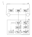
- FIG. 1 is a schematic diagram illustrating a configuration of a traffic system 1 according to the first embodiment.
- the traffic system 1 includes a plurality of vehicles 10 that operate on a track, and a vehicle control device 20 that controls the operation of the vehicles 10.
- a station is an example of a stop position.
- the vehicle 10 stops at each station.
- the passenger gets on and off the vehicle 10 at the station.
- the vehicle 10 operates with power supplied from an overhead line.
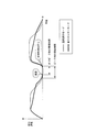
- FIG. 2 is a diagram showing an outline of the traffic system 1 according to the first embodiment.
- the vehicle control device 20 generates an operation plan for the vehicle 10.
- the vehicle control device 20 operates the vehicle 10 in an operation mode according to the operation plan.
- the operation mode is information indicating how to operate between stations.
- a normal operation mode that is a standard operation mode
- an energy saving mode that consumes less energy and has a longer operation time than the normal operation mode.
- the normal operation mode after the operation of the vehicle 10 is started, the vehicle 10 is accelerated until reaching a predetermined speed (restricted speed), and then the speed is maintained, and deceleration starts when the vehicle 10 reaches a predetermined position. Mode.
- the vehicle 10 In the energy saving mode, after the operation of the vehicle 10 starts, the vehicle 10 is accelerated to a predetermined speed, coasted when the speed of the vehicle 10 reaches a predetermined speed, and decelerated when the vehicle 10 reaches a predetermined position.
- This is the operation mode to be started. That is, the normal operation mode maintains the speed by powering when the speed of the vehicle 10 reaches a predetermined speed, whereas the energy saving mode starts coasting when the speed of the vehicle 10 reaches the predetermined speed. .
- the energy saving mode there is no energy consumption related to the power running, so that the energy consumption is reduced compared to the normal operation mode.
- the speed gradually decreases during coasting it takes longer to reach the station in the energy saving mode than in the normal operation mode.
- the vehicle 10 operates in either the normal operation mode or the energy saving mode.
- the time required for getting on and off may be sufficiently shorter than the standard stop time.
- the vehicle control device 20 ensures the time required for getting on and off even if the vehicle 10 is operated in the energy saving mode between the station and the station in front thereof to shorten the stop time. can do.
- the vehicle control device 20 allows the vehicle 10 to travel between the station and the station in front of it in the normal operation mode, so that the time required for getting on and off is sufficient. Can be secured. Thereby, the vehicle control apparatus 20 can reduce the power consumption of the vehicle 10, without impairing a passenger's convenience.
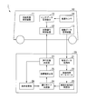
- the vehicle 10 includes an automatic train security device 11 (ATP: Automatic Train Protection), an automatic operation control device 12 (ATO: Automatic Train Operation), and an operation data management device 13.
- the automatic train security device 11 is a device that automatically stops or decelerates the vehicle 10 when the vehicle 10 tries to travel beyond a stop signal and when the speed of the vehicle 10 exceeds a predetermined speed.
- the automatic operation control device 12 operates the vehicle 10 in the operation mode acquired from the vehicle control device 20.
- the operation data management device 13 collects data related to the operation of the vehicle 10.
- the operation data management device 13 transmits data related to the operation of the vehicle 10 to the vehicle control device 20.
- the data relating to the operation of the vehicle 10 includes, for example, a station stopping rate, a station starting rate, a boarding time, and a stopping time for each station.
- the automatic train security device 11 and the automatic operation control device 12 specify the position of the vehicle 10 and control the speed of the vehicle 10 based on the position.
- the automatic train security device 11 and the automatic operation control device 12 specify the position of the vehicle 10 by communicating with a ground unit provided on the ground.
- the ground unit transmits information indicating the position where the ground unit is provided and information on the speed limit.
- the vehicle control device 20 includes an operation data acquisition unit 21, an operation history database 22, an entry / exit required time specification unit 23, an operation mode determination unit 24, an index value specification unit 25, a condition change unit 26, and an operation plan determination unit 27.
- the vehicle control device 20 generates a daily operation plan.
- the vehicle control device 20 transmits the operation mode according to the operation plan to each vehicle 10.
- As a standard operation plan the departure time of the vehicle 10 and the lap time of the track at each station are determined.
- the standard operation plan is determined by the departure time and the lap time when each vehicle 10 operates between all stations in the normal operation mode and stops at each station for a predetermined time (for example, 30 seconds).
- the operation data acquisition unit 21 collects data related to the operation of the vehicle 10 from the operation data management device 13 included in each vehicle 10 and records it in the operation history database 22.
- the operation history database 22 stores data relating to past operations of the vehicle 10.
- the operation history database 22 includes the date, day of the week, information indicating whether or not the day is a holiday, information on the event of the day, time, station name, traveling direction, number of passengers at the station stop, number of passengers at the station departure, boarding time, and station stop.
- the time is stored in association. Among these, the time, the station name, the number of boarding when the station stops, the number of boarding when leaving the station, the getting-on / off time, and the station stopping time are information transmitted from the operation data management device 13.
- the boarding / departure time specifying unit 23 predicts boarding / departure time for each station at each departure time determined in the standard operation plan based on information stored in the operation history database 22.
- the boarding / exiting time specifying unit 23 predicts boarding / exiting time based on, for example, a Bayesian model, a K-Means algorithm, or other prediction algorithms.
- the required time for getting on and off part 23 predicts the number of passengers and the number of people to get off at each station at each departure time, and the value obtained by multiplying the time required for boarding by the number of passengers
- the required time for getting on and off part 23 predicts the number of passengers and the number of people to get off at each station at each departure time, and the value obtained by multiplying the time required for boarding by the number of passengers
- the operation mode determination unit 24 determines the operation mode of each vehicle 10 based on the required time for getting on / off predicted by the required time for getting on / off unit 23. Specifically, the operation mode determination unit 24 sets the operation mode of the vehicle 10 to the energy saving mode when the required time of getting on and off at each station while the vehicle 10 goes around the track is shorter than a specified getting on / off time (for example, 15 seconds). To decide. The operation mode determination unit 24 determines the operation mode of the vehicle 10 to be the normal operation mode when the required time of getting on and off at each station while the vehicle 10 goes around the track is equal to or longer than the specified getting on / off time.
- the specified boarding / alighting time is a value smaller than a value obtained by subtracting a permissible value (margin) for boarding time (5 seconds in this embodiment) from a stop time (30 seconds in this embodiment) in the standard operation plan (that is, In this embodiment, it is less than 25 seconds).
- the specified boarding / alighting time is equal to or more than the value obtained by subtracting the difference in operation time between the normal operation mode and the energy saving mode (15 seconds in this embodiment) from the stop time in the standard operation plan (that is, 15 seconds in this embodiment). Above).
- the index value specifying unit 25 is based on the total power consumption (total energy consumption), the operation complexity index, and the passenger convenience index when the vehicle 10 is operated in the operation mode determined by the operation mode determination unit 24.
- the index value of the operation plan is calculated.
- the operation complexity index is a value indicating the operation complexity of the automatic operation control device 12, and indicates a higher value as the operation mode is changed more frequently.
- the passenger convenience index is a value that indicates the convenience of the transportation system 1 for passengers when the operation plan is adopted, and is used when the vehicle 10 is operated in the operation mode determined by the operation mode determination unit 24. The higher the difference between the time (stopping time) and the time required for getting on and off, and the higher the boarding rate and waiting time, the higher the value.
- the condition change unit 26 changes the specified boarding / alighting time that the operation mode determination unit 24 uses to determine the operation mode.
- the operation plan determination unit 27 adopts the operation plan related to the smallest one of the index values calculated based on different specified boarding times as the operation plan of the vehicle 10 on the day.
- the operation plan determination unit 27 transmits the operation mode related to the adopted operation plan to the automatic operation control device 12 of each vehicle 10.
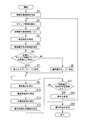
- FIG. 3 is a flowchart showing the operation of the vehicle control device 20 according to the first embodiment.
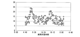
- 4A, 4B, and 4C are diagrams illustrating examples of data handled by the vehicle control device 20 according to the first embodiment.
- the vehicle control device 20 creates a daily operation plan before starting the operation of the first flight.
- the boarding / exiting time specifying unit 23 is based on the data related to the past operation of the vehicle 10 recorded in the operation history database 22, and the boarding / exiting time for passengers at each station at each time of day on which the operation plan is created. Is identified (step S1).
- FIG. 4A is a diagram illustrating an example of a result of specifying the required time for getting on and off at each time. Points plotted on the same time in FIG. 4A indicate different stations.
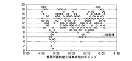
- the operation mode determination unit 24 calculates the gap time between the time required for getting on and off at each station and the stop time based on the time required for getting on and off specified by the time required for getting on and off 23 and the margin of the boarding time (Ste S2).
- the gap time is a value obtained by subtracting the time required for getting on and off and the margin from the stop time.
- the operation mode determination unit 24 selects the departure times of the starting stations of the vehicle 10 one by one, and executes the processes of steps S4 to S8 shown below (step S3).
- the operation mode determination unit 24 determines the time at which the vehicle 10 finishes orbiting the track for each departure time selected in step S3 based on the lap time required for the vehicle 10 to make a round of the track in the standard operation plan ( (End time) is specified (step S4). That is, in this embodiment, the section from the departure from the first station to the arrival at the first station is the operation section of the vehicle 10.
- the operation mode determination unit 24 specifies the departure time of each station through which the vehicle 10 passes from the departure time selected in step S3 to the end time (step S5).
- the operation mode determination unit 24 determines whether or not all gap times for the specified departure time calculated in step S2 are greater than a predetermined determination value (step S6). Comparing the gap time with a predetermined determination value is equivalent to comparing the required boarding / alighting time with the specified boarding / alighting time. That is, the determination value corresponds to a value obtained by subtracting the specified boarding / alighting time and the margin from the stop time.
- FIG. 4B is a diagram illustrating an example of a gap between the time required for getting on and off and the stopping time for each time. Points plotted on the same time in FIG. 4B indicate different stations.
- step S6 determines the operation mode while the vehicle 10 goes around the track to the energy saving mode (step S7). ).
- the operation mode determination unit 24 determines that at least one gap time is equal to or less than the predetermined determination value (step S6: NO)
- the operation mode while the vehicle 10 goes around the track is changed to the normal operation mode. Determine (step S8).
- the operation mode determination part 24 determines the operation mode of the vehicle 10 for every round (for every operation section). Thereby, since the operation mode is not changed while the vehicle 10 goes around the track, the vehicle control device 20 can simplify the operation.
- FIG. 4C is a diagram illustrating a relationship between the departure time of the vehicle 10 at the first departure station and the operation mode.
- the index value specifying unit 25 operates each vehicle 10 in the operation mode determined by the operation mode determination unit 24.
- the power consumption is calculated (step S9).
- the power consumption is calculated based on, for example, the vehicle weight calculated based on the number of passengers getting on and off at each station, which is calculated by the required time for getting on and off 23 for specifying the required time for getting on and off.
- the index value specifying unit 25 specifies the operation mode switching count determined by the operation mode determining unit 24 as an operation complexity index (step S10).
- the operation mode switching frequency is the sum of the number of times the operation mode of each vehicle 10 is switched from the normal operation mode to the energy saving mode and the number of times the vehicle 10 is switched from the energy saving mode to the normal operation mode.
- the operation mode is not switched while the vehicle 10 goes around the track. Therefore, the switching of the operation mode occurs at the timing when the vehicle 10 departs from the starting station again after going around the track.
- the index value specifying unit 25 calculates the total difference between the required boarding time calculated in step S1 and the boarding time when the vehicle 10 is operated in the operation mode determined by the operation mode determining unit 24. It is specified as a sex index (step S11).
- the index value specifying unit 25 calculates a sum value obtained by multiplying the calculated power consumption, the operation complexity index, and the passenger convenience index by a weighting factor as an index value of the operation plan (step S12). .
- the weighting factors of the calculated power consumption, the operation complexity index, and the passenger convenience index are appropriately set by the administrator of the transportation system 1. For example, if power consumption and passenger convenience are more important than operation complexity, the administrator of the traffic system 1 sets a low weighting factor for the operation complexity index to reduce power consumption and passenger convenience index. Set a high weighting factor.
- the operation plan determination unit 27 determines whether or not the index value specification by the index value specifying unit 25 has been performed a predetermined number of times or more (step S13).
- the condition changing unit 26 changes the condition relating to the determination of the operation mode.
- the conditions related to the determination of the operation mode are a boarding time margin and a determination value. Changing the boarding time margin or judgment value is equivalent to changing the specified boarding / alighting time.
- the operation mode determination part 24 returns to step S2, and determines the operation mode of each vehicle 10 again.
- the operation plan determination unit 27 determines that the specified number of index values by the index value specifying unit 25 is a predetermined number or more (step S13: YES)
- the operation plan determination unit 24 determines the combination of operation modes determined by the operation mode determination unit 24. Among them, the one with the smallest index value identified by the index value identifying unit 25 is determined as a daily operation plan (step S15). Thereby, the operation plan determination part 27 can generate
- the vehicle 10 can be operated in an operation mode according to an operation plan that balances power consumption, operational complexity, and passenger convenience.
- a traffic system 1 according to the second embodiment will be described.
- the vehicle control device 20 generates an operation plan that balances power consumption, operation complexity, and passenger convenience, and the vehicle 10 follows the operation plan. It will be operated.
- the automatic operation control device 12 of each vehicle 10 performs calculation in real time based on the operation plan generated by the vehicle control device 20 to switch the operation mode.
- FIG. 5 is a schematic block diagram showing the configuration of the traffic system 1 according to the second embodiment.
- the vehicle 10 according to the second embodiment further includes a weight sensor 14 and a sensor data management device 15 in addition to the configuration of the first embodiment.
- the weight sensor 14 measures the weight of the vehicle 10.
- the sensor data management device 15 calculates the weight measured by the weight sensor 14 and the weight measured by the vehicle 10 (hereinafter referred to as a preceding vehicle) that operates in front of the vehicle 10 (hereinafter referred to as the own vehicle) on which the own device is mounted. to manage.
- FIG. 6 is a flowchart showing the operation of the automatic operation control device 12 according to the second embodiment.
- the automatic operation control device 12 receives the operation mode from the vehicle control device 20 (step S101).
- the automatic operation control device 12 operates the vehicle 10 according to the operation mode (step S102).
- the sensor data management device 15 acquires sensor data related to the time required for getting on and off from the preceding vehicle (step S103).
- Examples of sensor data relating to the required boarding / exiting time include the number of passengers and the boarding / exiting time.
- the number of passengers can be obtained, for example, by counting the number of passengers getting on and off with a human sensor or a camera provided at the door of the preceding vehicle.
- the boarding / alighting time can be obtained, for example, by measuring the time from the time when a passenger is detected by a human sensor or camera provided on the door of the preceding vehicle to the time when the passenger is no longer detected.
- the automatic operation control device 12 specifies the required boarding / alighting time based on the sensor data acquired by the sensor data management device 15 (step S104).
- the automatic operation control device 12 determines whether or not the specified boarding / alighting time is shorter than the standard boarding / alighting time (step S105).
- the standard boarding / alighting time used by the automatic operation control device 12 may be a time different from the standard boarding / alighting time used by the vehicle control device 20.
- the automatic operation control device 12 causes the host vehicle to operate in the operation mode determined by the vehicle control device 20 (step S106) when it is determined that the specified getting-on / off time is equal to or more than the reference getting-on / off time (step S105: NO).
- step S105: YES when it determines with the automatic operation control apparatus 12 having determined the specific boarding / alighting time to be less than reference
- the automatic operation control device 12 of each vehicle 10 performs calculation in real time based on the operation plan generated by the vehicle control device 20 to switch the operation mode. Do. Thereby, the automatic operation control apparatus 12 can aim at the energy saving of operation more accurately, without impairing operation
- the operation mode may be determined for each station.
- the operation mode changes between stations, which increases the operation complexity index.
- the present invention is not limited to this.
- it may be permitted to delay the departure time by a predetermined allowable time from a predetermined departure time.
- the operation complexity index increases as the number of departure time changes increases or the delay time increases.
- the automatic operation control device 12 for the subsequent vehicle may switch the operation of the own vehicle to the energy saving mode regardless of the time required for getting on and off.
- the boarding / exiting time specifying unit 23 specifies the boarding / exiting time based on information stored in the operation history database 22 is described, but the present invention is not limited thereto.
- the ticket gates at each station can specify the boarding station and the departure station from a ticket or commuter pass.
- the time required for getting on and off may be specified based on the number of passengers at each station specified from the data collected at the ticket gates at each station.
- the boarding / exiting time specifying unit 23 specifies the boarding / exiting time based on the number of boarding / exiting persons at each station. Even if the number of passengers is the same, the time required for passengers may become longer as the boarding rate of the vehicle 10 is higher. Therefore, in another embodiment, the boarding / exiting time specifying unit 23 may specify the boarding / exiting time based on the number of passengers at each station and the boarding rate. Similarly to the second embodiment, the automatic operation control device 12 may specify the required time for getting on and off based on the number of passengers at each station and the boarding rate.
- the automatic operation control device 12 specifies the required time for getting on and off based on the sensor data related to the required time for getting on and off the preceding vehicle.
- the sensor data management device 15 can acquire the relationship between the sensor data related to the boarding / alighting time at each station and the boarding / alighting time.
- the automatic operation control device 12 may estimate the past boarding / alighting time associated with a value close to the sensor data related to the boarding / alighting time as the boarding / alighting time at the station where the host vehicle stops next.
- the automatic operation control device 12 operates the vehicle in the operation mode determined by the vehicle control device 20 when the specified getting-on / off time is equal to or more than the reference getting-on time, and the getting-on / off time is based on the reference time.
- the vehicle is operated in the energy saving mode when it is less than the getting on / off time.
- the automatic operation control apparatus 12 can suppress more the power consumption concerning driving
- the automatic operation control device 12 when the service provider places more emphasis on improving customer convenience than reducing power consumption, the automatic operation control device 12 is usually used when the specified boarding / departing time is equal to or longer than the standard boarding / alighting time.
- the vehicle may be operated in the operation mode, and the vehicle may be operated in the operation mode determined by the vehicle control device 20 when the required boarding / exiting time is less than the reference getting-on / off time.
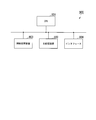
- FIG. 7 is a schematic block diagram illustrating a configuration of a computer 900 according to at least one embodiment.
- the computer 900 includes a CPU 901, a main storage device 902, an auxiliary storage device 903, and an interface 904.
- the vehicle control device 20 and the automatic operation control device 12 described above are each mounted on a computer 900.
- the operation of each processing unit described above is stored in the auxiliary storage device 903 in the form of a program.
- the CPU 901 reads a program from the auxiliary storage device 903, develops it in the main storage device 902, and executes the above processing according to the program.
- the auxiliary storage device 903 is an example of a tangible medium that is not temporary.
- Other examples of the non-temporary tangible medium include a magnetic disk, a magneto-optical disk, a CD-ROM, a DVD-ROM, and a semiconductor memory connected via the interface 904.
- the program may be for realizing a part of the functions described above. Further, the program may be a so-called difference file (difference program) that realizes the above-described function in combination with another program already stored in the auxiliary storage device 903.
- difference file difference program
- the vehicle control device determines an operation plan based on an index value obtained from energy consumption and operational complexity or passenger convenience. Thereby, the vehicle control apparatus can determine the operation mode which balanced energy consumption, the complexity of operation, or the convenience of a passenger.
Abstract
Description
本願は、2014年3月25日に、日本に出願された特願2014-061917号に基づき優先権を主張し、その内容をここに援用する。 The present invention relates to a vehicle control device, a traffic system, a vehicle control method, and a program thereof.
This application claims priority based on Japanese Patent Application No. 2014-061917 filed in Japan on March 25, 2014, the contents of which are incorporated herein by reference.
オペレーションの複雑化または乗客の利便性低下は、消費エネルギの低減とトレードオフとなる。
本発明は、消費エネルギと、オペレーションの複雑性または乗客の利便性とのバランスをとった運行モードを決定することができる車両制御装置、交通システム、車両制御方法及びプログラムを提供する。 However, in the technique described in
Complicated operations or reduced convenience for passengers trades off energy consumption.
The present invention provides a vehicle control device, a traffic system, a vehicle control method, and a program capable of determining an operation mode that balances energy consumption with operational complexity or passenger convenience.
[概要]
以下、図面を参照しながら実施形態について詳しく説明する。
図1は、第1の実施形態に係る交通システム1の構成を示す概略図である。
本実施形態に係る交通システム1は、軌道上を運行する複数の車両10と、当該車両10の運行を制御する車両制御装置20とを備える。軌道上には複数の駅が設けられている。駅は、停車位置の一例である。車両10は各駅で停車する。乗客は駅において車両10に乗降する。車両10は架線から電力の供給を受けて運行する。 << First Embodiment >>
[Overview]
Hereinafter, embodiments will be described in detail with reference to the drawings.
FIG. 1 is a schematic diagram illustrating a configuration of a
The
車両制御装置20は、車両10の運行計画を生成する。車両制御装置20は、当該運行計画に従った運行モードで車両10を運行させる。
運行モードとは、駅間をどのように運行するかを示す情報である。本実施形態に係る運行モードは、標準の運行モードである通常運行モードと、当該通常運行モードより消費エネルギが少なくかつ運行時間が長い省エネルギーモードとの2種類である。通常運行モードは、車両10の運行開始後、車両10を所定の速度(制限速度)になるまで加速させ、その後当該速度を維持させ、車両10が所定の位置に達した時に減速を開始する運行モードである。省エネルギーモードは、車両10の運行開始後、車両10を所定の速度になるまで加速させ、車両10の速度が所定の速度に達した時に惰行させ、車両10が所定の位置に達した時に減速を開始させる運行モードである。つまり、通常運行モードが、車両10の速度が所定の速度に達した時に力行により当該速度を維持するのに対し、省エネルギーモードは、車両10の速度が所定の速度に達した時に惰行を開始する。省エネルギーモードでは当該力行に係るエネルギーの消費がないため、通常運行モードと比較して消費エネルギーが少なくなる。他方、惰行時は速度が徐々に減速していくため、省エネルギーモードでは、通常運行モードと比較して駅に到着するまでの時間が長くなる。 FIG. 2 is a diagram showing an outline of the
The
The operation mode is information indicating how to operate between stations. There are two types of operation modes according to this embodiment: a normal operation mode that is a standard operation mode, and an energy saving mode that consumes less energy and has a longer operation time than the normal operation mode. In the normal operation mode, after the operation of the
これにより、車両制御装置20は、乗客の利便性を損なうことなく、車両10の消費電力を削減することができる。 The
Thereby, the
車両10は、自動列車保安装置11(ATP:Automatic Train Protection)と、自動運行制御装置12(ATO:Automatic Train Operation)と、稼働データ管理装置13とを備える。
自動列車保安装置11は、車両10が停止信号を越えて進行しようとした場合、および車両10の速度が所定の速度を超過した場合に、自動的に車両10を停止または減速させる装置である。
自動運行制御装置12は、車両制御装置20から取得した運行モードで車両10を運行させる。 [Configuration of Vehicle 10]
The
The automatic
The automatic
車両制御装置20は、稼働データ取得部21、稼働履歴データベース22、乗降所要時間特定部23、運行モード決定部24、指標値特定部25、条件変更部26、運行計画決定部27を備える。車両制御装置20は、一日の運行計画を生成する。車両制御装置20は、各車両10に当該運行計画に係る運行モードを送信する。標準の運行計画として、各駅における車両10の発車時刻及び軌道の周回時間が定められている。標準の運行計画は、各車両10がすべての駅間を通常運行モードで運行し、各駅において所定の時間(例えば、30秒)停車する場合の発車時刻及び周回時間によって定められる。 [Configuration of Vehicle Control Device 20]
The
乗降所要時間特定部23は、例えばベイジアンモデル、K-Meansアルゴリズムまたはその他の予測アルゴリズムに基づいて、乗降所要時間を予測する。乗降所要時間の算出方法としては、例えば、乗降所要時間特定部23が、各発車時刻における駅ごとの乗車人数及び降車人数を予測し、一人あたりの乗車に要する時間に乗車人数を乗算した値と、一人あたりの降車に要する時間に降車人数を乗算した値とを加算することで、算出する方法が挙げられる。 The boarding / departure
The boarding / exiting
運行計画決定部27は、異なる規定乗降時間に基づいて算出された指標値のうち最小のものに係る運行計画を、当日の車両10の運行計画として採用する。運行計画決定部27は、採用した運行計画に係る運行モードを各車両10の自動運行制御装置12に送信する。 The
The operation
本実施形態に係る車両制御装置20の動作について説明する。
図3は、第1の実施形態に係る車両制御装置20の動作を示すフローチャートである。
図4A、図4B、及び図4Cは、第1の実施形態に係る車両制御装置20で扱われるデータの一例を示す図である。
車両制御装置20は、始発便の運行を開始する前に、一日の運行計画を作成する。
まず、乗降所要時間特定部23は、稼働履歴データベース22に記録されている過去の車両10の運行に係るデータに基づいて、運行計画を作成する日の各時刻における駅ごとの乗客の乗降所要時間を特定する(ステップS1)。図4Aは、時刻ごとの乗降所要時間の特定結果の一例を示す図である。図4Aにおいて同じ時刻上にプロットされた点は、それぞれ異なる駅を示す。 [Operation]
Operation | movement of the
FIG. 3 is a flowchart showing the operation of the
4A, 4B, and 4C are diagrams illustrating examples of data handled by the
The
First, the boarding / exiting
まず、運行モード決定部24は、標準の運行計画において車両10が軌道を一周するのに要する周回時間に基づいて、ステップS3で選択した発車時刻ごとに、車両10が軌道を周回し終える時刻(終着時刻)を特定する(ステップS4)。つまり、本実施形態では、始発駅を出発してから当該始発駅に到着するまでの区間が、車両10の運行区間である。
次に、運行モード決定部24は、ステップS3で選択した発車時刻から終着時刻までの間に当該車両10が経由する各駅の発車時刻を特定する(ステップS5)。次に、運行モード決定部24は、ステップS2で算出した特定した発車時刻についての全てのギャップ時間が所定の判定値より大きいか否かを判定する(ステップS6)。ギャップ時間と所定の判定値とを比較することは、乗降所要時間と規定乗降時間とを比較することと等価である。つまり、判定値は、停車時間から規定乗降時間とマージンとを減算した値に相当する。図4Bは、時刻ごとの乗降所要時間と停車時間のギャップの一例を示す図である。図4Bにおいて同じ時刻上にプロットされた点は、それぞれ異なる駅を示す。 Next, the operation
First, the operation
Next, the operation
このように、運行モード決定部24は、車両10の運行モードを周回ごと(運行区間ごと)に決定する。これにより、車両10が軌道を一周する間に運行モードの変更が生じないため、車両制御装置20は、オペレーションの単純化を図ることができる。図4Cは、始発駅における車両10の発車時刻とその運行モードの関係を示す図である。 When it is determined that all the gap times are greater than the predetermined determination value (step S6: YES), the operation
Thus, the operation
本実施形態では、車両10が軌道を一周する間、運行モードが切り替わらない。そのため、運行モードの切り替わりは、車両10が軌道を一周した後に、再度始発駅から発車するタイミングで発生する。 Next, the index
In the present embodiment, the operation mode is not switched while the
[概要]
第2の実施形態に係る交通システム1について説明する。
第1の実施形態にかかる交通システム1は、車両制御装置20が消費電力と、オペレーションの複雑性と、乗客の利便性とのバランスをとった運行計画を生成し、車両10が当該運行計画に従って運行するものである。第2の実施形態に係る交通システム1では、各車両10の自動運行制御装置12が、車両制御装置20が生成した運行計画をベースにリアルタイムに計算を行って運行モードの切り替えを行う。 << Second Embodiment >>
[Overview]
A
In the
第2の実施形態に係る車両10は、第1の実施形態の構成に加え、重量センサ14とセンサデータ管理装置15とをさらに備えるものである。
重量センサ14は、車両10の重量を測定する。
センサデータ管理装置15は、重量センサ14が測定した重量と、自装置を搭載する車両10(以下、自車両という)の前方を運行する車両10(以下、先行車両という)が測定した重量とを管理する。 FIG. 5 is a schematic block diagram showing the configuration of the
The
The
The sensor
第2の実施形態に係る交通システム1の動作について説明する。
図6は、第2の実施形態に係る自動運行制御装置12の動作を示すフローチャートである。
車両10の発車時刻になると、自動運行制御装置12は、車両制御装置20から運行モードを受信する(ステップS101)。自動運行制御装置12は、当該運行モードに従って車両10を運行させる(ステップS102)。 [Operation]
The operation of the
FIG. 6 is a flowchart showing the operation of the automatic
When the departure time of the
例えば、上述した実施形態では、運行モードとして通常運行モードと省エネルギーモードの2種類を用いる場合について説明したが、これに限られない。例えば、他の実施形態では、運行時間と消費電力が異なる複数の省エネルギーモードについても計算が行われ、待ち時間に応じた適切な運行モードが選択されても良い。 As described above, the embodiment has been described in detail with reference to the drawings. However, the specific configuration is not limited to that described above, and various design changes and the like can be made.
For example, in the embodiment described above, the case where two types of operation modes, that is, the normal operation mode and the energy saving mode are used has been described, but the present invention is not limited to this. For example, in another embodiment, calculation may be performed for a plurality of energy saving modes having different operation times and power consumption, and an appropriate operation mode corresponding to the waiting time may be selected.
図7は、少なくとも1つの実施形態に係るコンピュータ900の構成を示す概略ブロック図である。
コンピュータ900は、CPU901、主記憶装置902、補助記憶装置903、インタフェース904を備える。
上述の車両制御装置20及び自動運行制御装置12は、それぞれコンピュータ900に実装される。そして、上述した各処理部の動作は、プログラムの形式で補助記憶装置903に記憶されている。CPU901は、プログラムを補助記憶装置903から読み出して主記憶装置902に展開し、当該プログラムに従って上記処理を実行する。 <Computer configuration>
FIG. 7 is a schematic block diagram illustrating a configuration of a
The
The
さらに、当該プログラムは、前述した機能を補助記憶装置903に既に記憶されている他のプログラムとの組み合わせで実現するもの、いわゆる差分ファイル(差分プログラム)であっても良い。 The program may be for realizing a part of the functions described above.
Further, the program may be a so-called difference file (difference program) that realizes the above-described function in combination with another program already stored in the
10 車両
11 自動列車保安装置
12 自動運行制御装置
13 稼働データ管理装置
14 重量センサ
15 センサデータ管理装置
20 車両制御装置
21 稼働データ取得部
22 稼働履歴データベース
23 乗降所要時間特定部
24 運行モード決定部
25 指標値特定部
26 条件変更部
27 運行計画決定部
900 コンピュータ
901 CPU
902 主記憶装置
903 補助記憶装置
904 インタフェース DESCRIPTION OF
902
Claims (9)
- 各停車位置において乗客が車両に乗降するために要する乗降所要時間に基づいて各車両の運行モードを、当該運行モードの1つである通常運行モードか、当該通常運行モードより消費エネルギが少なくかつ運行時間が長い省エネルギーモードかの、いずれにするかを決定する運行モード決定部と、
前記運行モード決定部が決定した運行モードで前記車両を運行させた時の総消費エネルギが大きいほど高い値となる指標値を特定する指標値特定部と、
前記車両それぞれの運行モードを前記指標値が最も小さくなる運行モードに決定する運行計画決定部と
を備える車両制御装置。 Based on the time required for passengers to get on and off the vehicle at each stop position, the operation mode of each vehicle is the normal operation mode which is one of the operation modes, or less energy consumption and operation than the normal operation mode. An operation mode determination unit that determines which of the energy saving modes is long,
An index value identifying unit that identifies an index value that is higher as the total energy consumption when the vehicle is operated in the operation mode determined by the operation mode determination unit;
A vehicle control apparatus comprising: an operation plan determining unit that determines an operation mode of each of the vehicles to an operation mode with the smallest index value. - 前記運行モード決定部は、前記乗降所要時間が規定乗降時間より短い場合に、当該車両の運行モードを、前記省エネルギーモードに決定する
請求項1に記載の車両制御装置。 The vehicle control device according to claim 1, wherein the operation mode determination unit determines the operation mode of the vehicle to be the energy saving mode when the required time for getting on and off is shorter than a specified getting on and off time. - 前記車両は、複数の停車位置を含む運行区間を周回し、
前記運行モード決定部は、前記車両が前記運行区間におけるすべての前記乗降所要時間が規定乗降時間より短い場合に、運行モードを省エネモードに決定する
請求項1または請求項2に記載の車両制御装置。 The vehicle circulates an operation section including a plurality of stop positions,
The vehicle control device according to claim 1, wherein the operation mode determination unit determines the operation mode to be an energy saving mode when all the required time for getting on and off in the operation section is shorter than a specified getting on / off time. . - 各停車位置における過去の前記車両の運行の情報に基づいて、当該停車位置における前記車両の乗降所要時間を特定する乗降所要時間特定部
をさらに備え、
前記運行モード決定部は、前記乗降所要時間特定部が特定した乗降所要時間に基づいて各車両の運行モードを決定する
請求項1から請求項3の何れか1項に記載の車両制御装置。 Based on the past information of the vehicle operation at each stop position, further comprising a boarding / exiting time specifying unit for specifying the time required for boarding / exiting the vehicle at the stop position,
The vehicle control device according to any one of claims 1 to 3, wherein the operation mode determination unit determines an operation mode of each vehicle based on the required time for getting on and off specified by the required time for getting on and off. - 前記車両は、複数の停車位置を含む運行区間を周回し、
前記運行モード決定部は、前記車両が前記運行区間を周回するときの前記運行モードを決定する
請求項1から請求項4の何れか1項に記載の車両制御装置。 The vehicle circulates an operation section including a plurality of stop positions,
The vehicle control device according to any one of claims 1 to 4, wherein the operation mode determination unit determines the operation mode when the vehicle goes around the operation section. - 請求項1から請求項5の何れか1項に記載の車両制御装置と、
前記車両制御装置が決定した運行モードで運行する車両と
を備える交通システム。 The vehicle control device according to any one of claims 1 to 5,
And a vehicle that operates in the operation mode determined by the vehicle control device. - 前記車両は、
先行車両の乗車率に基づいて次の停車位置における乗降時間を推定し、当該乗降時間に基づいて運行モードを決定する
請求項6に記載の交通システム。 The vehicle is
The traffic system according to claim 6, wherein a boarding / alighting time at a next stop position is estimated based on a boarding rate of a preceding vehicle, and an operation mode is determined based on the boarding / alighting time. - 各停車位置において乗客が車両に乗降するために要する乗降所要時間に基づいて各車両の運行モードを、当該運行モードの1つである通常運行モードか、当該通常運行モードより消費エネルギが少なくかつ運行時間が長い省エネルギーモードかの、いずれにするかを決定する運行モード決定ステップと、
前記決定した運行モードで前記車両を運行させた時の総消費エネルギが大きいほど高い値となる指標値を特定する指標値特定ステップと、
前記車両それぞれの運行モードを前記指標値が最も小さくなる運行モードに決定する運行計画決定ステップと
を含む車両制御方法。 Based on the time required for passengers to get on and off the vehicle at each stop position, the operation mode of each vehicle is the normal operation mode which is one of the operation modes, or less energy consumption and operation than the normal operation mode. An operation mode decision step for deciding which one of the energy saving modes is long, and
An index value specifying step for specifying an index value that becomes higher as the total energy consumption when operating the vehicle in the determined operation mode;
A vehicle control method comprising: an operation plan determination step for determining an operation mode of each of the vehicles to an operation mode with the smallest index value. - コンピュータを、
各停車位置において乗客が車両に乗降するために要する乗降所要時間に基づいて各車両の運行モードを、当該運行モードの1つである通常運行モードか、当該通常運行モードより消費エネルギが少なくかつ運行時間が長い省エネルギーモードかの、いずれにするかを決定する運行モード決定部、
前記運行モード決定部が決定した運行モードで前記車両を運行させた時の総消費エネルギが大きいほど高い値となる指標値を特定する指標値特定部、
前記車両それぞれの運行モードを前記指標値が最も小さくなる運行モードに決定する運行計画決定部
として機能させるためのプログラム。 Computer
Based on the time required for passengers to get on and off the vehicle at each stop position, the operation mode of each vehicle is the normal operation mode which is one of the operation modes, or less energy consumption and operation than the normal operation mode. Operation mode decision unit that decides which mode to save energy, which is long time,
An index value identifying unit that identifies an index value that is higher as the total energy consumption is greater when the vehicle is operated in the operation mode determined by the operation mode determination unit;
The program for functioning as an operation plan determination part which determines the operation mode of each said vehicle to the operation mode in which the said index value becomes the smallest.
Priority Applications (3)
| Application Number | Priority Date | Filing Date | Title |
|---|---|---|---|
| US15/126,120 US9975563B2 (en) | 2014-03-25 | 2014-12-15 | Vehicle control device, transport system, vehicle control method, and program |
| SG11201607725VA SG11201607725VA (en) | 2014-03-25 | 2014-12-15 | Vehicle control device, transport system, vehicle control method, and program |
| GB1615985.7A GB2538480B (en) | 2014-03-25 | 2014-12-15 | Vehicle control device, transport system, vehicle control method, and program |
Applications Claiming Priority (2)
| Application Number | Priority Date | Filing Date | Title |
|---|---|---|---|
| JP2014061917A JP6279375B2 (en) | 2014-03-25 | 2014-03-25 | VEHICLE CONTROL DEVICE, TRANSPORTATION SYSTEM, VEHICLE CONTROL METHOD, AND PROGRAM |
| JP2014-061917 | 2014-03-25 |
Publications (1)
| Publication Number | Publication Date |
|---|---|
| WO2015145892A1 true WO2015145892A1 (en) | 2015-10-01 |
Family
ID=54194459
Family Applications (1)
| Application Number | Title | Priority Date | Filing Date |
|---|---|---|---|
| PCT/JP2014/083110 WO2015145892A1 (en) | 2014-03-25 | 2014-12-15 | Vehicle control device, transport system, vehicle control method, and program |
Country Status (5)
| Country | Link |
|---|---|
| US (1) | US9975563B2 (en) |
| JP (1) | JP6279375B2 (en) |
| GB (1) | GB2538480B (en) |
| SG (1) | SG11201607725VA (en) |
| WO (1) | WO2015145892A1 (en) |
Cited By (1)
| Publication number | Priority date | Publication date | Assignee | Title |
|---|---|---|---|---|
| CN109955871A (en) * | 2017-12-25 | 2019-07-02 | 比亚迪股份有限公司 | The signal control method of rail traffic, device and system |
Families Citing this family (14)
| Publication number | Priority date | Publication date | Assignee | Title |
|---|---|---|---|---|
| JP6366165B2 (en) * | 2014-01-23 | 2018-08-01 | 三菱重工エンジニアリング株式会社 | Travel control device, vehicle, traffic system, control method, and program |
| JP6222841B2 (en) * | 2014-03-25 | 2017-11-01 | 三菱重工業株式会社 | Operation management device, train control method and program |
| US10953901B2 (en) | 2016-03-29 | 2021-03-23 | Mitsubishi Electric Corporation | Train operation control system and train operation control method |
| US10279823B2 (en) * | 2016-08-08 | 2019-05-07 | General Electric Company | System for controlling or monitoring a vehicle system along a route |
| IT201700014889A1 (en) * | 2017-02-10 | 2018-08-10 | Iveco France Sas | FORECAST SYSTEM FOR THE RESIDUAL AUTONOMY OF AN ELECTRIC VEHICLE |
| EP3363678B1 (en) * | 2017-02-21 | 2023-03-01 | Siemens Rail Automation S.A.U. | System and method for optimizing energy consumption of a guided vehicle during acceleration of the latter |
| EP3595952B1 (en) | 2017-03-17 | 2022-01-12 | Cummins Inc. | Controlling a vehicle equipped with engine start-stop control logic in response to vehicle stop event type |
| JP7220551B2 (en) * | 2018-11-27 | 2023-02-10 | ナブテスコ株式会社 | Platform door device control parameter generation device, platform door device, and platform door system |
| JP7355695B2 (en) | 2020-04-02 | 2023-10-03 | トヨタ自動車株式会社 | Transportation system, operation control device, and operation control method |
| JP7315510B2 (en) | 2020-04-02 | 2023-07-26 | トヨタ自動車株式会社 | AUTONOMOUS VEHICLE OPERATION MANAGEMENT DEVICE AND OPERATION MANAGEMENT METHOD |
| JP7368299B2 (en) | 2020-04-02 | 2023-10-24 | トヨタ自動車株式会社 | Transportation system, operation control device, and operation control method |
| JP7477390B2 (en) | 2020-07-29 | 2024-05-01 | 矢崎エナジーシステム株式会社 | Control device, vehicle management system and vehicle management program |
| KR20230041920A (en) * | 2021-09-17 | 2023-03-27 | 한국철도기술연구원 | Method And Apparatus for Real-Time Scheduling for Resolving Delay of Train Operation |
| CN115257884B (en) * | 2022-08-19 | 2024-04-26 | 交控科技股份有限公司 | Rail transit energy-saving control method and device based on passenger carrying state |
Citations (3)
| Publication number | Priority date | Publication date | Assignee | Title |
|---|---|---|---|---|
| JPH09156507A (en) * | 1995-12-13 | 1997-06-17 | Toshiba Corp | Train total traffic control device |
| JP2013230775A (en) * | 2012-04-27 | 2013-11-14 | Toshiba Corp | Apparatus and method for controlling operation, and control program |
| JP2013247851A (en) * | 2012-05-30 | 2013-12-09 | Hitachi Ltd | Vehicle system |
Family Cites Families (1)
| Publication number | Priority date | Publication date | Assignee | Title |
|---|---|---|---|---|
| US8220572B2 (en) * | 2006-06-15 | 2012-07-17 | Railpower, Llc | Multi-power source locomotive selection |
-
2014
- 2014-03-25 JP JP2014061917A patent/JP6279375B2/en active Active
- 2014-12-15 WO PCT/JP2014/083110 patent/WO2015145892A1/en active Application Filing
- 2014-12-15 US US15/126,120 patent/US9975563B2/en active Active
- 2014-12-15 GB GB1615985.7A patent/GB2538480B/en active Active
- 2014-12-15 SG SG11201607725VA patent/SG11201607725VA/en unknown
Patent Citations (3)
| Publication number | Priority date | Publication date | Assignee | Title |
|---|---|---|---|---|
| JPH09156507A (en) * | 1995-12-13 | 1997-06-17 | Toshiba Corp | Train total traffic control device |
| JP2013230775A (en) * | 2012-04-27 | 2013-11-14 | Toshiba Corp | Apparatus and method for controlling operation, and control program |
| JP2013247851A (en) * | 2012-05-30 | 2013-12-09 | Hitachi Ltd | Vehicle system |
Cited By (1)
| Publication number | Priority date | Publication date | Assignee | Title |
|---|---|---|---|---|
| CN109955871A (en) * | 2017-12-25 | 2019-07-02 | 比亚迪股份有限公司 | The signal control method of rail traffic, device and system |
Also Published As
| Publication number | Publication date |
|---|---|
| GB2538480A (en) | 2016-11-16 |
| US9975563B2 (en) | 2018-05-22 |
| US20170072974A1 (en) | 2017-03-16 |
| SG11201607725VA (en) | 2016-11-29 |
| GB2538480B (en) | 2020-08-19 |
| JP2015182654A (en) | 2015-10-22 |
| GB201615985D0 (en) | 2016-11-02 |
| JP6279375B2 (en) | 2018-02-14 |
Similar Documents
| Publication | Publication Date | Title |
|---|---|---|
| WO2015145892A1 (en) | Vehicle control device, transport system, vehicle control method, and program | |
| US8774992B2 (en) | Operation support device and automatic operation device | |
| CN102612480B (en) | Elevator group management system | |
| JP5972829B2 (en) | Operation management device, operation management method, vehicle, vehicle traffic system and program | |
| JP6096596B2 (en) | Operation management device, operation management method, vehicle, vehicle traffic system and program | |
| EP2541506A1 (en) | Method and system for managing a flow of passengers on a platform | |
| CN103373648B (en) | Elevator device | |
| EP2923913A1 (en) | Automatic train operation system | |
| WO2007039925A1 (en) | Device for controlling elevator operation | |
| US20210311498A1 (en) | Operation management device, operation management method, and transportation system | |
| CN112997226A (en) | Information processing method and information processing system | |
| CN111232772A (en) | Method, system, computer-readable storage medium for controlling operation of elevator | |
| WO2015145900A1 (en) | Service management device, train control method, and program | |
| JP2000067389A (en) | Vehicle allocation system | |
| JP4732343B2 (en) | Elevator group management control device | |
| CN113096449B (en) | Flight big data-based shutdown position resource arrangement method and system | |
| CN110304503B (en) | Elevator transfer system | |
| KR101167456B1 (en) | Elevator group management device and elevator group management method | |
| JP2020124940A (en) | Automatic parking system | |
| WO2018181964A1 (en) | Vehicle assignment management device, vehicle assignment management method, and mobility system | |
| CN104203790A (en) | Elevator control device | |
| JP6650421B2 (en) | Vehicle dispatch management device, vehicle dispatch management method, mobility system, and program | |
| CN116547188B (en) | Railway system, operation management device, and operation management method | |
| Xu et al. | Signal priority control method for emergency vehicles at intersections based on wireless communication technology | |
| JP2004123242A (en) | Elevator group control system and its method |
Legal Events
| Date | Code | Title | Description |
|---|---|---|---|
| 121 | Ep: the epo has been informed by wipo that ep was designated in this application |
Ref document number: 14887569 Country of ref document: EP Kind code of ref document: A1 |
|
| WWE | Wipo information: entry into national phase |
Ref document number: 15126120 Country of ref document: US |
|
| ENP | Entry into the national phase |
Ref document number: 201615985 Country of ref document: GB Kind code of ref document: A Free format text: PCT FILING DATE = 20141215 |
|
| WWE | Wipo information: entry into national phase |
Ref document number: 1615985.7 Country of ref document: GB |
|
| NENP | Non-entry into the national phase |
Ref country code: DE |
|
| 122 | Ep: pct application non-entry in european phase |
Ref document number: 14887569 Country of ref document: EP Kind code of ref document: A1 |