JP6650421B2 - Vehicle dispatch management device, vehicle dispatch management method, mobility system, and program - Google Patents
Vehicle dispatch management device, vehicle dispatch management method, mobility system, and program Download PDFInfo
- Publication number
- JP6650421B2 JP6650421B2 JP2017069149A JP2017069149A JP6650421B2 JP 6650421 B2 JP6650421 B2 JP 6650421B2 JP 2017069149 A JP2017069149 A JP 2017069149A JP 2017069149 A JP2017069149 A JP 2017069149A JP 6650421 B2 JP6650421 B2 JP 6650421B2
- Authority
- JP
- Japan
- Prior art keywords
- vehicle
- target vehicle
- route
- vehicles
- destination
- Prior art date
- Legal status (The legal status is an assumption and is not a legal conclusion. Google has not performed a legal analysis and makes no representation as to the accuracy of the status listed.)
- Active
Links
Images


Description
本発明は、配車管理装置、配車管理方法、モビリティシステム、およびプログラムに関する。 The present invention relates to a vehicle allocation management device, a vehicle allocation management method, a mobility system, and a program.
距離が離れた2点間で人員を輸送する場合に、バスやタクシーなどの輸送手段が用いられている。また特許文献1には、自動走行する車両を用いて定時運行サービスとデマンド運行サービスとを共存させる技術が開示されている。 When transporting personnel between two points that are far apart, transportation methods such as buses and taxis are used. Further, Patent Literature 1 discloses a technique in which a scheduled operation service and a demand operation service coexist using an automatically traveling vehicle.
輸送手段のコストを低減するために、自動運転により輸送手段を制御することが望まれている。一方で、自動運転技術を用いて輸送手段を安全かつ確実に目的地まで輸送する技術は確立されていない。
本発明の目的は、自動運転技術を用いて車両に安全かつ確実にルートを走行させる配車管理装置、配車管理方法、モビリティシステム、およびプログラムを提供することにある。
In order to reduce the cost of the vehicle, it is desired to control the vehicle by automatic driving. On the other hand, there is no established technology for safely and reliably transporting transportation means to a destination using automatic driving technology.
An object of the present invention is to provide a vehicle allocation management device, a vehicle allocation management method, a mobility system, and a program that allow a vehicle to travel a route safely and reliably using an automatic driving technique.
本発明の第1の態様によれば、配車管理装置は、走行すべきルートを対象車両に通知するルート通知部と、前記対象車両を含む複数の車両のそれぞれから複数のタイミングで位置情報を受信する位置受信部と、前記複数の車両の位置情報に基づいて、前記対象車両の走行可能な範囲を示す許可範囲を、複数のタイミングで前記対象車両に通知する範囲通知部と、目的地の入力を受け付ける目的地入力部と、前記目的地に基づいて前記複数の車両の中から前記対象車両を決定する車両決定部と、前記目的地に基づいて経由地を決定する経由地決定部と、前記対象車両への乗員の乗車が完了したか否かを判定する乗車判定部と、を備え、前記ルート通知部は、前記車両決定部が前記対象車両を決定したときに前記経由地へ向かうルートを前記対象車両に通知し、前記対象車両への乗員の乗車が完了したときに前記目的地へ向かうルートを前記対象車両に通知する。 According to the first aspect of the present invention, the vehicle allocation management device receives the route information at a plurality of timings from each of the plurality of vehicles including the target vehicle, and a route notification unit that notifies the target vehicle of the route to be driven. A position receiving unit, a range notifying unit that notifies the target vehicle at a plurality of timings an allowable range indicating a range in which the target vehicle can travel, based on the position information of the plurality of vehicles, and a destination input. A destination input unit that accepts, a vehicle determination unit that determines the target vehicle from the plurality of vehicles based on the destination, a via location determination unit that determines a via location based on the destination, A boarding determination unit that determines whether or not the boarding of the occupant to the target vehicle has been completed, and the route notification unit determines a route to the stopover point when the vehicle determination unit determines the target vehicle. Said object Notify both, and notifies the route toward the destination when the occupant of the ride to the subject vehicle has been completed to said subject vehicle.
本発明の第3の態様によれば、第2の態様に係る配車管理装置は、前記目的地へ輸送すべき乗員の数の入力を受け付ける乗員数入力部と、前記乗員の数に基づいて前記対象車両の数を決定する車両数決定部とを備え、前記車両決定部は、一定時間内にすべての前記対象車両が前記目的地に到着するように、前記車両数決定部が決定した台数の対象車両を決定するものであってよい。 According to a third aspect of the present invention, the vehicle allocation management device according to the second aspect includes an occupant number input unit that receives an input of the number of occupants to be transported to the destination, and A vehicle number determining unit that determines the number of target vehicles, wherein the vehicle determining unit determines the number of vehicles determined by the vehicle number determining unit so that all the target vehicles arrive at the destination within a predetermined time. The target vehicle may be determined.
本発明の第7の態様によれば、第4または第6の態様に係る配車管理装置は、前記乗車判定部は、前記車両が前記経由地に到着し、かつ前記車両のドアが閉じられたときに、前記対象車両への乗員の乗車が完了したと判定するものであってよい。 According to a seventh aspect of the present invention, in the vehicle allocation management device according to the fourth or sixth aspect, the boarding determination unit determines that the vehicle has arrived at the stopover point and the door of the vehicle has been closed. At this time, it may be determined that the occupant has completed boarding the target vehicle.
本発明の第8の態様によれば、モビリティシステムは、複数の車両と、第1から第7の何れかの態様に係る配車管理装置とを備え、前記複数の車両のそれぞれは、前記配車管理装置から受信した前記ルートおよび前記許可範囲に基づいて、前記ルート上かつ前記許可範囲内を走行する。 According to an eighth aspect of the present invention, a mobility system includes a plurality of vehicles and the vehicle allocation management device according to any one of the first to seventh aspects, wherein each of the plurality of vehicles includes the vehicle allocation management The vehicle travels on the route and within the permission range based on the route and the permission range received from the device.
本発明の第9の態様によれば、配車管理方法は、走行すべきルートを対象車両に通知することと、前記対象車両を含む複数の車両のそれぞれから複数のタイミングで位置情報を受信することと、前記複数の車両の位置情報に基づいて、前記対象車両の走行可能な範囲を示す許可範囲を、複数のタイミングで前記対象車両に通知することと、目的地の入力を受け付けることと、前記目的地に基づいて前記複数の車両の中から前記対象車両を決定することと、前記目的地に基づいて経由地を決定することと、前記対象車両への乗員の乗車が完了したか否かを判定することと、前記対象車両を決定したときに前記経由地へ向かうルートを前記対象車両に通知することと、前記対象車両への乗員の乗車が完了したときに前記目的地へ向かうルートを前記対象車両に通知することとを有する。 According to a ninth aspect of the present invention, the dispatch management method includes notifying a target vehicle of a route to be traveled and receiving position information at a plurality of timings from each of a plurality of vehicles including the target vehicle. Based on the position information of the plurality of vehicles, notifying the target vehicle of a permission range indicating a range in which the target vehicle can travel, at a plurality of timings, receiving an input of a destination, Determining the target vehicle from the plurality of vehicles based on the destination, determining a waypoint based on the destination, and determining whether or not the occupant has boarded the target vehicle Judging, notifying the target vehicle of a route to the stopover point when the target vehicle is determined, and setting a route to the destination when the occupant has completed boarding the target vehicle. And a notifying the target vehicle.
本発明の第10の態様によれば、プログラムは、コンピュータに、走行すべきルートを対象車両に通知することと、前記対象車両を含む複数の車両のそれぞれから複数のタイミングで位置情報を受信することと、前記複数の車両の位置情報に基づいて、前記対象車両の走行可能な範囲を示す許可範囲を、複数のタイミングで前記対象車両に通知することと、目的地の入力を受け付けることと、前記目的地に基づいて前記複数の車両の中から前記対象車両を決定することと、前記目的地に基づいて経由地を決定することと、前記対象車両への乗員の乗車が完了したか否かを判定することと、前記対象車両を決定したときに前記経由地へ向かうルートを前記対象車両に通知することと、前記対象車両への乗員の乗車が完了したときに前記目的地へ向かうルートを前記対象車両に通知することとを実行させる。
According to the tenth aspect of the present invention, the program notifies the computer of the route to be traveled to the target vehicle, and receives the position information at a plurality of timings from each of the plurality of vehicles including the target vehicle. And, based on the position information of the plurality of vehicles, notifying the target vehicle at a plurality of timings of a permission range indicating a range in which the target vehicle can travel, and accepting an input of a destination, Determining the target vehicle from among the plurality of vehicles based on the destination, determining a waypoint based on the destination, and determining whether or not the occupant has boarded the target vehicle Determining that the target vehicle has been determined, and notifying the target vehicle of a route to the stopover point when the target vehicle has been determined. The Cow root to execute the method comprising: notifying the target vehicle.
上記態様のうち少なくとも1つの態様によれば、配車管理装置は、車両に安全かつ確実にルートを走行させることができる。 According to at least one of the above aspects, the vehicle allocation management device can cause the vehicle to travel the route safely and reliably.
〈第1の実施形態〉
以下、図面を参照しながら実施形態について詳しく説明する。
図1は、第1の実施形態に係るモビリティシステムを備える施設の外観を示す図である。
第1の実施形態に係るモビリティシステム2は、待合施設1に設けられる。つまり、第1の実施形態に係る待合施設1は、モビリティシステム2を備える施設の一例である。待合施設1には、ターミナルビル11、待機場12、ターミナルビル11と待機場12との間に設けられた道路13が設けられる。ターミナルビル11は、輸送機械Aに搭乗する乗客が手続を行う施設である。ターミナルビル11には、道路13に面したゲート111が複数設けられている。各ゲート111は、乗客が所有するチケット等を認証することで、乗客の名前および便名を特定する。待機場12は、輸送機械Aが待機するスペースである。輸送機械Aの例としては、船舶や飛行機などが挙げられる。待合施設1の例としては、港湾や空港などが挙げられる。
待合施設1では、モビリティシステム2が備える大型輸送車両L1および小型輸送車両L2により、乗客がターミナルビル11と待機場12との間で輸送される。モビリティシステム2は、大型輸送車両L1および小型輸送車両L2の走行を制御する。なお、ターミナルビル11には、大型輸送車両L1用のゲート111と小型輸送車両L2用のゲート111とが設けられる。
<First embodiment>
Hereinafter, embodiments will be described in detail with reference to the drawings.
FIG. 1 is a diagram illustrating an appearance of a facility including the mobility system according to the first embodiment.
The mobility system 2 according to the first embodiment is provided in a waiting facility 1. That is, the waiting facility 1 according to the first embodiment is an example of a facility including the mobility system 2. The waiting facility 1 is provided with a
In the waiting facility 1, passengers are transported between the
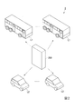
図2は、第1の実施形態に係るモビリティシステムの構成を示す概略図である。
モビリティシステム2は、複数の大型輸送車両L1と、複数の小型輸送車両L2と、配車管理装置200とを備える。以下、大型輸送車両L1および小型輸送車両L2を総称して車両Lという。モビリティシステム2は、空港の運営を管理する図示しない搭乗管理システム、およびターミナルビル11のゲート111を通過する乗客を管理する図示しないゲートシステムとネットワークを介して接続される。
FIG. 2 is a schematic diagram illustrating a configuration of the mobility system according to the first embodiment.
The mobility system 2 includes a plurality of large transport vehicles L1, a plurality of small transport vehicles L2, and a
大型輸送車両L1および小型輸送車両L2は、配車管理装置200から送信される走行すべきルートと走行可能な許可範囲とに基づいて自動走行する。許可範囲とは、一定時間内において他の車両Lに接触しないで走行することができる範囲である。大型輸送車両L1は、ターミナルビル11のゲート111のうち、配車管理装置200から待機場12ごとに定められたゲート111で乗客を乗車させ、所定の待機場12へ移動する。小型輸送車両L2は、ターミナルビル11のゲート111のうち配車管理装置200から指定されたゲート111で乗客を乗車させ、乗客が指定した待機場12へ移動する。小型輸送車両L2には、例えば優先搭乗客など限られた乗客のみが乗車可能であってもよい。小型輸送車両L2に乗車可能な乗客であるか否かは、例えばゲート111におけるチケットの読み取りなどにより識別することができる。
The large transport vehicle L1 and the small transport vehicle L2 automatically travel based on the route to be traveled transmitted from the vehicle
図3は、第1の実施形態に係る車両の構成を示す概略ブロック図である。
車両L(大型輸送車両L1および小型輸送車両L2)は、情報受信部L01、位置計測部L02、開閉検知部L03、情報送信部L04、走行制御部L05を備える。
情報受信部L01は、配車管理装置200からルートおよび許可範囲を示す情報を受信する。
位置計測部L02は、車両Lの位置を計測する。具体的には、位置計測部L02は、通路に設置された位置情報を読み取り可能な識別子の読み取り、車軸回転数などを用いた自律航法、GNSS(Global Navigation Satellite System)の利用などにより、位置情報を計測する。
開閉検知部L03は、車両Lのドアの開閉を検知する。
情報送信部L04は、位置計測部L02が計測した位置情報および開閉検知部L03が検知した開閉情報を配車管理装置200に送信する。
走行制御部L05は、情報受信部L01が受信したルートおよび許可範囲、ならびに位置計測部L02が計測した位置情報に基づいて、車両Lがルート上かつ許可範囲内を走行するように制御する。たとえば、走行制御部L05は、ルートに基づいて、車両Lがルート上を走行するようにステアリングおよび走行速度を制御する。また走行制御部L05は、現在位置と速度とに基づいて、車両Lの位置が許可範囲を超えないように走行速度の加減速を制御する。走行制御部L05は、車両Lの位置が許可範囲を超えた場合に、車両Lを停止させる。
FIG. 3 is a schematic block diagram illustrating a configuration of the vehicle according to the first embodiment.
The vehicle L (the large transport vehicle L1 and the small transport vehicle L2) includes an information receiving unit L01, a position measuring unit L02, an opening / closing detecting unit L03, an information transmitting unit L04, and a travel control unit L05.
The information receiving unit L01 receives information indicating the route and the permitted range from the vehicle
The position measurement unit L02 measures the position of the vehicle L. More specifically, the position measurement unit L02 reads the position information installed in the passage, which can read the position information, autonomous navigation using the axle rotation speed, the use of GNSS (Global Navigation Satellite System), and the like. Is measured.
The opening / closing detection unit L03 detects opening / closing of a door of the vehicle L.
The information transmission unit L04 transmits the position information measured by the position measurement unit L02 and the opening / closing information detected by the opening / closing detection unit L03 to the vehicle
The traveling control unit L05 controls the vehicle L to travel on the route and within the permitted range based on the route and the permitted range received by the information receiving unit L01 and the position information measured by the position measuring unit L02. For example, the traveling control unit L05 controls the steering and the traveling speed based on the route so that the vehicle L travels on the route. Further, the traveling control unit L05 controls the acceleration / deceleration of the traveling speed based on the current position and the speed so that the position of the vehicle L does not exceed the allowable range. The traveling control unit L05 stops the vehicle L when the position of the vehicle L exceeds the permitted range.
配車管理装置200は、車両Lにルートと許可範囲とを通知する。
図4は、第1の実施形態に係る配車管理装置の構成を示す概略ブロック図である。
配車管理装置200は、輸送機械データベース201、車両データベース202、配車指示受信部203、車両数決定部204、第1経由地決定部205、第1車両決定部206、第2経由地決定部207、第2車両決定部208、ゲート情報受信部209、乗降判定部210、ルート通知部211、位置受信部212、範囲通知部213を備える。
The vehicle
FIG. 4 is a schematic block diagram illustrating the configuration of the vehicle allocation management device according to the first embodiment.
The vehicle
輸送機械データベース201は、輸送機械Aの便名と、当該飛行機が待機する待機場12の識別情報と、当該輸送機械Aに搭乗する乗客が待機するターミナルビル11のゲート111とを関連付けて記憶する。
車両データベース202は、車両Lの識別情報と、車両Lの位置情報と、車両Lの状態(待機中、迎車中、輸送中)とを記憶する。
The
The
配車指示受信部203は、搭乗管理システムから配車指示を受信する。配車指示には、便名と搭乗者のリストとが含まれる。便名は、目的地を示す情報の一例である。つまり、配車指示受信部203は、目的地入力部の一例である。また、搭乗者のリストは乗員数を示す情報の一例である。つまり、配車指示受信部203は、乗員数入力部の一例でもある。
The dispatch
車両数決定部204は、配車指示に含まれる搭乗者リストから車両Lの乗員数を特定し、当該乗員数に基づいて配車すべき大型輸送車両L1の数を決定する。例えば、車両数決定部204は、乗員数を大型輸送車両L1の定員で除算し、小数点以下を繰り上げることで大型輸送車両L1の数を算出することができる。
第1経由地決定部205は、配車指示に含まれる便名に関連付けられたゲート111を輸送機械データベース201から読み出し、これを大型輸送車両L1の経由地に決定する。
第1車両決定部206は、車両データベース202を参照し、待機中かつ第1経由地決定部205が決定したゲート111の位置に最も近い、車両数決定部204が決定した台数の大型輸送車両L1を、配車対象の大型輸送車両L1(対象車両)に決定する。このとき、第1車両決定部206は、大型輸送車両L1の位置に加え、大型輸送車両L1の残り燃料量(または充電量)から算出される走行可能距離や大型輸送車両L1の使用回数等に基づいて配車対象の大型輸送車両L1を決定してもよい。
The number-of-
The first
The first
第2経由地決定部207は、車両データベース202を参照し、複数の小型輸送車両L2用のゲート111(経由地候補)のうち、小型輸送車両L2が配車されていない小型輸送車両L2用のゲート111を、小型輸送車両L2の経由地に決定する。
第2車両決定部208は、車両データベース202を参照し、待機中かつ第2経由地決定部207が決定したゲート111の位置に最も近い小型輸送車両L2を、配車対象の小型輸送車両L2(対象車両)に決定する。このとき、第2車両決定部208は、小型輸送車両L2の位置に加え、小型輸送車両L2の残り燃料量(または充電量)から算出される走行可能距離や小型輸送車両L2の使用回数等に基づいて配車対象の小型輸送車両L2を決定してもよい。
The second
The second
ゲート情報受信部209は、ゲートシステムから、ゲート111におけるチケット等の認証により得られた名前および便名を受信する。便名は、目的地を示す情報の一例である。つまり、ゲート情報受信部209は、目的地入力部の一例である。
乗降判定部210は、車両Lからドアの開閉を示す信号を受信し、これに基づいて当該車両Lへの乗客の乗車または車両Lからの乗客の降車が完了したか否かを判定する。具体的には、乗降判定部210は、車両Lがゲート111に到着しており、かつ当該車両Lからドアが閉まったことを示す信号を受信したときに、乗客の乗車が完了したと判定する。また乗降判定部210は、車両Lが待機場12に到着しており、かつ当該車両Lからドアが閉まったことを示す信号を受信したときに、乗客の降車が完了したと判定する。
The gate
The getting on / off determining
ルート通知部211は、車両Lに走行すべきルートを通知する。具体的には、ルート通知部211は、第1車両決定部206が配車体操の大型輸送車両L1を決定したときに、当該大型輸送車両L1に、大型輸送車両L1の現在位置から第1経由地決定部205が決定したゲート111までのルートを通知する。またルート通知部211は、大型輸送車両L1への乗客の乗車が完了したときに、当該大型輸送車両L1に、大型輸送車両L1の現在位置から配車指示に含まれる便名によって特定される待機場12までのルートを通知する。また、ルート通知部211は、第2車両決定部208が配車体操の小型輸送車両L2を決定したときに、当該小型輸送車両L2に、小型輸送車両L2の現在位置から第2経由地決定部207が決定したゲート111までのルートを通知する。またルート通知部211は、小型輸送車両L2への乗客の乗車が完了したときに、当該小型輸送車両L2に、ゲート情報受信部209が当該小型輸送車両L2が配車されたゲート111で認証された情報に含まれる便名によって特定される待機場12までのルートを通知する。
The
位置受信部212は、各車両Lから現在位置を示す位置情報を受信し、車両データベース202を更新する。
範囲通知部213は、各車両Lに、他の車両Lとの接触せずに走行可能な範囲を示す許可範囲を通知する。具体的には、範囲通知部213は、以下の手順で、各車両Lの許可範囲を算出する。まず、範囲通知部213は、車両データベース202を参照し、各車両Lについて、現在位置から最大速度で走行した場合の走行範囲を算出する。そして、範囲通知部213は、各車両Lについて、当該車両Lの走行範囲から他の車両Lの走行範囲との重複部分を除くことで、許可範囲を算出する。
The
The
第1の実施形態に係る車両Lの動作について説明する。
図5は、第1の実施形態に係る車両の動作を示すフローチャートである。
車両Lは、配車管理装置200からルートを受信すると、図5に示すフローチャートの動作を実行する。車両Lの情報受信部L01は、配車管理装置200から許可範囲を受信する(ステップS001)。次に、位置計測部L02は、車両Lの位置、速度、および進行方向を計測する(ステップS002)。情報送信部L04は、計測した位置、速度、および進行方向を配車管理装置200に送信する(ステップS003)
The operation of the vehicle L according to the first embodiment will be described.
FIG. 5 is a flowchart illustrating the operation of the vehicle according to the first embodiment.
When receiving the route from the vehicle
また、走行制御部L05は、車両Lが計測した位置、速度および進行方向に基づいて、車両Lが許可範囲から出ずにルート上を走行するように、車両Lの速度およびステアリングを制御する(ステップS004)。例えば、走行制御部L05は、以下の手順で速度およびステアリングを制御する。
まず、走行制御部L05は、車両Lの位置、速度、および進行方向に基づいて、車両Lがその進行方向上における許可範囲の境界で停止するために減速を開始すべきタイミング(範囲内減速タイミング)を算出する。範囲内減速タイミングが現在時刻以前である場合、許可範囲の境界で停止可能な速度に車両Lを減速させる。他方、範囲内減速タイミングが現在時刻より後である場合、走行制御部L05は、車両Lがルートの左折もしくは右折をするため、またはルートの終端で停止するために減速を開始すべきタイミング(ルート減速タイミング)を算出する。ルート減速タイミングが現在時刻以前である場合、左折もしくは右折が可能な速度または停止可能な速度になるように車両Lを減速させる。他方、ルート減速タイミングが現在時刻より後である場合、走行制御部L05は、車両Lの速度を最大速度まで加速させ、または速度を維持する。
また、走行制御部L05は、車両Lの位置がルートの左折または右折のポイントに接近した場合、車両Lの速度が左折または右折が可能な速度であるか否かを判定する。左折または右折が可能な速度である場合、走行制御部L05は、ルートに従ってステアリングを制御する。他方、左折または右折が可能な速度でない場合、走行制御部L05は、許可範囲内で停止するように車両Lの速度およびステアリングを制御する。
このとき、走行制御部L05は、許可範囲内か否かの判定のみならず、車両Lに搭載された別個の機能により危機を回避するように走行を制御してもよい。この場合においても、車両Lは許可範囲から出ないように走行を制御する。また、万一車両Lが許可範囲から出た場合、走行制御部L05は、車両Lを停止させる。
Further, the traveling control unit L05 controls the speed and steering of the vehicle L based on the position, speed, and traveling direction measured by the vehicle L so that the vehicle L travels on the route without going out of the permitted range ( Step S004). For example, the traveling control unit L05 controls the speed and the steering in the following procedure.
First, based on the position, speed, and traveling direction of the vehicle L, the traveling control unit L05 determines a timing at which the vehicle L should start decelerating to stop at the boundary of the allowable range in the traveling direction (in-range deceleration timing). ) Is calculated. If the in-range deceleration timing is before the current time, the vehicle L is decelerated to a speed that can be stopped at the boundary of the permitted range. On the other hand, when the in-range deceleration timing is later than the current time, the traveling control unit L05 determines the timing at which the vehicle L should start deceleration to make a left or right turn on the route or to stop at the end of the route (route). (Deceleration timing). If the route deceleration timing is before the current time, the vehicle L is decelerated so as to have a speed at which a left or right turn is possible or a speed at which a stop is possible. On the other hand, when the route deceleration timing is later than the current time, the traveling control unit L05 accelerates the speed of the vehicle L to the maximum speed or maintains the speed.
In addition, when the position of the vehicle L approaches a left or right turn point on the route, the traveling control unit L05 determines whether the speed of the vehicle L is a speed at which a left or right turn is possible. When the speed is such that a left turn or a right turn is possible, the traveling control unit L05 controls the steering according to the route. On the other hand, when it is not the speed at which the left turn or the right turn is possible, the traveling control unit L05 controls the speed and the steering of the vehicle L so as to stop within the allowable range.
At this time, the traveling control unit L05 may control traveling so as to avoid a crisis by using a separate function mounted on the vehicle L as well as determining whether or not the vehicle is within the allowable range. Also in this case, the vehicle L is controlled so as not to go out of the permitted range. If the vehicle L goes out of the permitted range, the traveling control unit L05 stops the vehicle L.
走行制御部L05は、車両Lの位置に基づいて、ルートの終端(ゲート111または待機場12)に到着したか否かを判定する(ステップS005)。車両Lがルートの終端に到着していない場合(ステップS005:NO)、情報受信部L01は、配車管理装置200から新たな許可範囲を受信したか否かを判定する(ステップS006)。情報受信部L01が配車管理装置200から新たな許可範囲を受信していない場合(ステップS006:NO)、車両Lは処理をステップS002に戻し、走行の制御を継続する。情報受信部L01が配車管理装置200から新たな許可範囲を受信した場合(ステップS006:YES)、情報受信部L01は、車両Lの走行の制御に用いる許可範囲を新たなものに更新する(ステップS007)。そして車両Lは処理をステップS002に戻し、走行の制御を継続する。
The traveling control unit L05 determines whether the vehicle has arrived at the end of the route (the
他方、車両Lがルートの終端に到着した場合(ステップS005:YES)、情報送信部L04は、ルートの終端に到着したことを示す到着情報を配車管理装置200に送信し(ステップS008)、処理を終了する。
これにより、車両Lは、許可範囲から出ることなくルート上を走行することができる。そして、配車管理装置200は車両Lがルートの終端に到着したか否かを認識することができる。
On the other hand, when the vehicle L has arrived at the end of the route (Step S005: YES), the information transmitting unit L04 transmits arrival information indicating that the vehicle has arrived at the end of the route to the vehicle allocation management device 200 (Step S008), and performs processing. To end.
Thereby, the vehicle L can travel on the route without going out of the permitted range. Then, the vehicle
図6は、第1の実施形態に係る配車管理装置による大型輸送車両の配車処理を示すフローチャートである。
搭乗管理システムは、輸送機械Aの準備が完了すると、当該輸送機械Aへ乗客を輸送するための車両Lの配車を指示する配車指示を配車管理装置200に送信する。
配車管理装置200の配車指示受信部203が、搭乗管理システムから配車指示を受信すると(ステップS101)、車両数決定部204は、受信した配車指示に含まれる乗客のリストから乗客数を算出し、これに基づいて配車すべき大型輸送車両L1の数を決定する(ステップS102)。
FIG. 6 is a flowchart illustrating a vehicle allocation process of a large-sized transport vehicle by the vehicle allocation management device according to the first embodiment.
When the preparation of the transport machine A is completed, the boarding management system transmits to the dispatch management apparatus 200 a dispatch instruction for dispatching the vehicle L for transporting the passenger to the transport machine A.
When the dispatch
次に、第1経由地決定部205は、受信した配車指示に含まれる便名に関連付けられたゲート111を輸送機械データベース201から読み出し、これを経由地に決定する(ステップS103)。第1車両決定部206は、車両データベース202を参照し、各大型輸送車両L1の位置を特定する(ステップS104)。第1車両決定部206は、状態が「待機中」であって、第1経由地決定部205が読み出したゲート111に最も近い大型輸送車両L1を、配車対象に決定する(ステップS105)。このとき、第1車両決定部206は、複数の大型輸送車両L1が連なって待機している場合、当該複数の大型輸送車両L1から配車すべき数の大型輸送車両L1を抽出して配車対象に決定するとよい。これにより、複数の大型輸送車両L1がゲート111に到着する時刻のばらつきを抑えることができる。第1車両決定部206は、配車対象の大型輸送車両L1を決定すると、車両データベース202における配車対象に決定した大型輸送車両L1の状態を「迎車中」に書きかえる。
配車指示受信部203は、ステップS101で受信した配車指示に対する応答として、第1車両決定部206が決定した大型輸送車両L1の識別情報を搭乗管理システムに通知する(ステップS106)。搭乗管理システムは、通知された大型輸送車両L1がすべて待機場12に到着したか否かを判定することで、輸送機械Aへの搭乗漏れを防ぐことができる。
Next, the first
The dispatch
次に、ルート通知部211は、配車対象の各大型輸送車両L1の現在位置からステップS103で決定した経由地のゲート111までのルートを計算する(ステップS107)。ルートの計算は、例えばダイクストラ法等のアルゴリズムにより実現される。ルート通知部211は、計算したルートを配車対象の各大型輸送車両L1に通知する(ステップS108)。これにより配車対象の各大型輸送車両L1は、ゲート111に向かって走行を開始する。
Next, the
以降、配車管理装置200は、配車対象の各大型輸送車両L1について並列に以下の処理を実行する。
Thereafter, the vehicle
乗降判定部210は、大型輸送車両L1から到着情報を受信したか否かを判定する(ステップS109)。到着情報を受信していない場合(ステップS109:NO)、乗降判定部210は、ステップS109による到着情報の受信の待機を継続する。他方、到着情報を受信した場合(ステップS109:YES)、乗降判定部210は、その大型輸送車両L1からドアを閉めたことを示す開閉情報を受信したか否かを判定する(ステップS110)。ドアを閉めたことを示す開閉情報を受信していない場合(ステップS110:NO)、乗降判定部210は、ステップS110による開閉情報の受信の待機を継続する。他方、ドアを閉めたことを示す開閉情報を受信した場合(ステップS110:YES)、乗降判定部210は、その大型輸送車両L1への乗車が完了したと判定する(ステップS111)。このとき、乗降判定部210は、車両データベース202におけるその大型輸送車両L1の状態を「輸送中」に変更する。
The getting on / off determining
大型輸送車両L1への乗車が完了すると、ルート通知部211は、配車指示に含まれる便名に関連付けられた待機場12を輸送機械データベース201から読み出す(ステップS112)。次に、ルート通知部211は、その大型輸送車両L1の現在位置から読み出した待機場12までのルートを計算する(ステップS113)。ルート通知部211は、計算したルートをその大型輸送車両L1に通知する(ステップS114)。これにより乗客の乗車が完了した大型輸送車両L1は、待機場12に向かって走行を開始する。
When the boarding of the large-sized transport vehicle L1 is completed, the
次に、乗降判定部210は、大型輸送車両L1から到着情報を受信したか否かを判定する(ステップS115)。到着情報を受信していない場合(ステップS115:NO)、乗降判定部210は、ステップS115による到着情報の受信の待機を継続する。他方、到着情報を受信した場合(ステップS115:YES)、乗降判定部210は、その大型輸送車両L1からドアを閉めたことを示す開閉情報を受信したか否かを判定する(ステップS116)。ドアを閉めたことを示す開閉情報を受信していない場合(ステップS116:NO)、乗降判定部210は、ステップS116による開閉情報の受信の待機を継続する。他方、ドアを閉めたことを示す開閉情報を受信した場合(ステップS116:YES)、乗降判定部210は、その大型輸送車両L1からの降車が完了したと判定する(ステップS117)。このとき、乗降判定部210は、車両データベース202におけるその大型輸送車両L1の状態を「待機中」に変更する。
これにより、配車管理装置200は、配車指示に基づいて、ゲート111で乗客を乗車させ、待機場12で乗客を降車させるように、大型輸送車両L1の走行を制御することができる。
Next, the getting on / off
Thereby, the
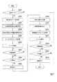
図7は、第1の実施形態に係る配車管理装置による小型輸送車両の配車処理を示すフローチャートである。
配車管理装置200は、定期的に図7に示す小型輸送車両L2のゲート111への配車処理を実行する。配車管理装置200の第2経由地決定部207は、車両データベース202を参照し、小型輸送車両L2用ゲート111のうち、小型輸送車両L2が配車されていない空きのゲート111の有無を判定する(ステップS201)。空きのゲート111が無い場合、すなわちすべての小型輸送車両L2用ゲート111に小型輸送車両L2が配車されている場合(ステップS201:NO)、配車管理装置200は、小型輸送車両L2のゲート111への配車処理を終了する。なお配車管理装置200は、所定時間の経過後に図7に示す配車処理を再度実行する。
FIG. 7 is a flowchart illustrating a vehicle allocation process of the small transport vehicle by the vehicle allocation management device according to the first embodiment.
The vehicle
他方、空きのゲート111がある場合(ステップS201:YES)、第2経由地決定部207は、当該ゲート111を経由地に決定する(ステップS202)。第2車両決定部208は、車両データベース202を参照し、各小型輸送車両L2の位置を特定する(ステップS203)。第2車両決定部208は、状態が「待機中」であって、第2経由地決定部207が読み出したゲート111に最も近い小型輸送車両L2を、配車対象に決定する(ステップS204)。第2車両決定部208は、配車対象の小型輸送車両L2を決定すると、車両データベース202における配車対象に決定した小型輸送車両L2の状態を「迎車中」に書きかえる。
On the other hand, when there is an empty gate 111 (step S201: YES), the second
次に、ルート通知部211は、配車対象の小型輸送車両L2の現在位置からステップS202で決定した経由地のゲート111までのルートを計算する(ステップS205)。ルート通知部211は、計算したルートを配車対象の小型輸送車両L2に通知する(ステップS206)。これにより配車対象の小型輸送車両L2は、ゲート111に向かって走行を開始する。
Next, the
次に、乗降判定部210は、小型輸送車両L2から到着情報を受信したか否かを判定する(ステップS207)。到着情報を受信していない場合(ステップS207:NO)、乗降判定部210は、ステップS207による到着情報の受信の待機を継続する。他方、到着情報を受信した場合(ステップS207:YES)、乗降判定部210は、その小型輸送車両L2からドアを閉めたことを示す開閉情報を受信したか否かを判定する(ステップS208)。ドアを閉めたことを示す開閉情報を受信していない場合(ステップS208:NO)、乗降判定部210は、ステップS208による開閉情報の受信の待機を継続する。他方、ドアを閉めたことを示す開閉情報を受信した場合(ステップS208:YES)、乗降判定部210は、その小型輸送車両L2への乗車が完了したと判定する(ステップS209)。このとき、乗降判定部210は、車両データベース202におけるその小型輸送車両L2の状態を「輸送中」に変更する。次に、ゲート情報受信部209は、ゲートシステムから、当該小型輸送車両L2が配送されたゲート111において認証された乗客の名前および便名を受信する(ステップS210)。小型輸送車両L2には、1名の乗客が乗車しても複数名の乗客が乗車してもよいが、各乗客は同一の輸送機械Aに搭乗するものとする。つまり、複数の乗客が乗車する場合、各乗客が搭乗する輸送機械Aの便名は同じである。
Next, the getting on / off
次に、ルート通知部211は、ステップS210で受信した便名に関連付けられた待機場12を輸送機械データベース201から読み出す(ステップS211)。次に、ルート通知部211は、その小型輸送車両L2の現在位置から、読み出した待機場12までのルートを計算する(ステップS212)。ルート通知部211は、計算したルートをその小型輸送車両L2に通知する(ステップS213)。これにより乗客の乗車が完了した小型輸送車両L2は、待機場12に向かって走行を開始する。
Next, the
次に、乗降判定部210は、小型輸送車両L2から到着情報を受信したか否かを判定する(ステップS214)。到着情報を受信していない場合(ステップS214:NO)、乗降判定部210は、ステップS214による到着情報の受信の待機を継続する。他方、到着情報を受信した場合(ステップS214:YES)、乗降判定部210は、その小型輸送車両L2からドアを閉めたことを示す開閉情報を受信したか否かを判定する(ステップS215)。ドアを閉めたことを示す開閉情報を受信していない場合(ステップS215:NO)、乗降判定部210は、ステップS116による開閉情報の受信の待機を継続する。他方、ドアを閉めたことを示す開閉情報を受信した場合(ステップS215:YES)、乗降判定部210は、その小型輸送車両L2からの降車が完了したと判定する(ステップS216)。このとき、乗降判定部210は、車両データベース202におけるその小型輸送車両L2の状態を「待機中」に変更する。
これにより、配車管理装置200は、小型輸送車両L2が配車されていないゲート111に小型輸送車両L2を配車し、当該小型輸送車両L2に、乗客に応じた待機場12まで乗客を輸送させることができる。
Next, the getting on / off
Thereby, the vehicle
なお、図6および図7に係る配車制御は、ゲート111で乗客を車両Lに乗車させ、待機場12で乗客を降車させるときの配車制御、すなわち輸送機械Aの出発時における配車制御であるが、配車管理装置200は、輸送機械Aの到着時も同様の配車制御を行う。この場合、配車管理装置200は、待機場12を経由地に設定し、ゲート111を目的地に設定する。
The dispatch control according to FIGS. 6 and 7 is the dispatch control when the passenger gets on the vehicle L at the
図8は、第1の実施形態に係る配車管理装置による車両の許可範囲の通知処理を示すフローチャートである。
配車管理装置200は、一定時間ごと(例えば、10秒ごと)に、各車両Lの許可範囲を更新して通知する。配車管理装置200の位置受信部212は、各車両Lから位置、速度、進行方向を受信する(ステップS301)。次に、範囲通知部213は、各車両Lについて、現在位置から最大速度で一定時間走行した場合の走行範囲を算出する(ステップS302)。次に、範囲通知部213は、複数の車両Lから車両Lを1つずつ選択し、各車両Lについて、以下に示すステップS304およびステップS305の処理を実行する(ステップS303)。範囲通知部213は、選択された車両Lについて、当該車両Lの走行範囲から他の車両Lの走行範囲との重複部分を除いた範囲を算出する。範囲通知部213は、当該範囲を選択された車両Lの許可範囲に決定する(ステップS304)。そして範囲通知部213は、当該許可範囲を車両Lに通知する(ステップS305)。
これにより、車両Lには、一定時間ごとに他の車両Lと接触せずに走行可能な許可範囲を通知することができる。
FIG. 8 is a flowchart illustrating a process of notifying the permitted range of the vehicle by the vehicle allocation management device according to the first embodiment.
The vehicle
This allows the vehicle L to be notified of the permitted range in which the vehicle L can travel without contact with another vehicle L at regular intervals.
以上、第1の実施形態によれば、配車管理装置200は、配車対象の車両Lに走行すべきルートを通知し、一定時間ごとに、複数の車両Lのそれぞれから位置情報を受信し、また受信した位置情報に基づいて、少なくとも配車対象の車両Lに、当該車両Lの走行可能な範囲を示す許可範囲を通知する。これにより、車両Lは、許可範囲に基づいて走行することで、他の車両Lとの接触を防ぎながら走行すことができ、またルートに基づいて走行することで、確実に目的地へ向かって走行することができる。つまり、第1の実施形態に係る配車管理装置200は、車両Lに走行すべきルートを安全かつ確実に走行させることができる。なお、第1の実施形態において、配車管理装置200は、すべての車両Lについて図8に示す許可範囲の通知を行うが、これに限られない。例えば、他の実施形態において配車対象となっていない車両L(待機中の車両L)が必ず停止している場合、配車管理装置200は、複数の車両Lのうち配車対象となっている車両L(待機中でない車両L)を特定し、これに対してのみ許可範囲を通知してもよい。
なお、他の実施形態においては、許可範囲が必ずしも一定時間ごとに通知されなくてもよい。つまり、許可範囲の通知は、複数のタイミングでなされれば、必ずしも周期的でなくてもよい。また、他の実施形態においては、車両Lの位置情報が必ずしも一定時間ごとに通知されなくてもよい。つまり、位置情報の通知は、複数のタイミングでなされれば、必ずしも周期的でなくてもよい。
As described above, according to the first embodiment, the
In other embodiments, the permitted range does not necessarily have to be notified at regular intervals. That is, the notification of the permitted range is not necessarily periodic as long as the notification is made at a plurality of timings. Further, in another embodiment, the position information of the vehicle L does not necessarily need to be notified at regular time intervals. That is, the notification of the position information is not necessarily periodic as long as the notification is made at a plurality of timings.
また、第1の実施形態によれば、配車管理装置200は、搭乗管理システムから乗客が搭乗する輸送機械Aの便名の入力を受け付け、これに基づいて複数の大型輸送車両L1の中から対象車両を決定する。これにより、配車管理装置200は、輸送機械Aに対応付けて大型輸送車両L1を配車することができる。また配車管理装置200は、目的地へ輸送すべき乗客の数に基づいて配車すべき大型輸送車両L1の数を決定する。これにより、配車管理装置200は、輸送機械Aの乗客の数に対し、過不足ない台数の大型輸送車両L1を配車することができる。また配車管理装置200は、配車対象の大型輸送車両L1を決定したときに経由地へ向かうルートを当該大型輸送車両L1に通知し、当該大型輸送車両L1への乗車が完了したときに目的地へ向かうルートを当該大型輸送車両L1に通知する。これにより、配車管理装置200は、輸送機械Aの出発の際に、乗客をゲート111で乗車させ、待機場12で降車させることができる。また、配車管理装置200は、輸送機械Aの到着の際に、乗客を待機場12で乗車させ、ゲート111で降車させることができる。
Further, according to the first embodiment, the
また、第1の実施形態によれば、配車管理装置200は、複数の小型輸送車両L2用のゲート111の中から小型輸送車両L2を配車すべきゲート111を決定し、当該ゲート111に基づいて複数の小型輸送車両L2の中から配車対象となる小型輸送車両L2を決定する
。これにより、配車管理装置200は、空いているゲート111に小型輸送車両L2を配車することができる。また配車管理装置200は、ゲート111で小型輸送車両L2に乗車した乗客が搭乗する輸送機械Aの便名を受信し、当該小型輸送車両L2への乗車が完了したときに、当該便名に関連付けられた待機場12へ向かうルートを小型輸送車両L2に通知する。これにより、配車管理装置200は、小型輸送車両L2により乗客の搭乗する輸送機械Aの待機場12まで乗客を輸送することができる。
Further, according to the first embodiment, the
また、第1の実施形態によれば、配車管理装置200は、車両Lが経由地に到着し、かつ車両Lのドアが閉じられたときに、当該車両Lへの乗車が完了したと判定する。これにより、車両Lの乗員が特別な処理を実行することなく、配車管理装置200に乗客の乗車完了を通知することができる。なお、他の実施形態においてはこれに限られず、例えばすべての乗客が乗車したときに、乗員が図示しないボタンを押下することで、乗車の完了が配車管理装置200に伝えられてもよい。
Further, according to the first embodiment, when the vehicle L arrives at the stopover and the door of the vehicle L is closed, the vehicle
以上、図面を参照して一実施形態について詳しく説明してきたが、具体的な構成は上述のものに限られることはなく、様々な設計変更等をすることが可能である。
例えば、第1の実施形態によれば、モビリティシステム2は、大型輸送車両L1と小型輸送車両L2の両方を備えるが、他の実施形態に係るモビリティシステム2は、大型輸送車両L1を備えないものであってもよい。この場合、モビリティシステム2は、小型輸送車両L2によりすべての乗客をゲート111と待機場12との間で輸送する。
また例えば、他の実施形態に係るモビリティシステム2は、小型輸送車両L2を備えないものであってもよい。この場合、モビリティシステム2は、大型輸送車両L1によりすべての乗客をゲート111と待機場12との間で輸送する。
As described above, one embodiment has been described in detail with reference to the drawings. However, the specific configuration is not limited to the above, and various design changes and the like can be made.
For example, according to the first embodiment, the mobility system 2 includes both the large transport vehicle L1 and the small transport vehicle L2, but the mobility system 2 according to another embodiment does not include the large transport vehicle L1. It may be. In this case, the mobility system 2 transports all the passengers between the
Further, for example, the mobility system 2 according to another embodiment may not include the small transport vehicle L2. In this case, the mobility system 2 transports all the passengers between the
また、第1の実施形態によれば、モビリティシステム2は、待合施設1の乗客輸送に適用されるが、これに限られない。例えば、他の実施形態においては、モビリティシステム2がバスやタクシーによる都市交通システムや、工場内の輸送システムなどに適用されてもよい。つまり、他の実施形態においては、目的地および経由地が、待機場12およびゲート111でなくてもよく、車両Lに乗車する乗員が輸送機械Aの乗客でなくてもよい。
Further, according to the first embodiment, the mobility system 2 is applied to the passenger transportation of the waiting facility 1, but is not limited thereto. For example, in another embodiment, the mobility system 2 may be applied to a city transportation system using a bus or a taxi, a transportation system in a factory, or the like. In other words, in other embodiments, the destination and the waypoint need not be the
図9は、少なくとも1つの実施形態に係るコンピュータの構成を示す概略ブロック図である。
コンピュータ9は、CPU91、主記憶装置92、補助記憶装置93、インタフェース94を備える。
上述の配車管理装置200および車両Lは、コンピュータ9を備える。そして、上述した各処理部の動作は、プログラムの形式で補助記憶装置93に記憶されている。CPU91は、プログラムを補助記憶装置93から読み出して主記憶装置92に展開し、当該プログラムに従って上記処理を実行する。また、CPU91は、プログラムに従って、上述した各データベースに対応する記憶領域を主記憶装置92または補助記憶装置93に確保する。
FIG. 9 is a schematic block diagram illustrating a configuration of a computer according to at least one embodiment.
The computer 9 includes a
The above-described vehicle
補助記憶装置93の例としては、HDD(Hard Disk Drive)、SSD(Solid State Drive)、磁気ディスク、光磁気ディスク、CD−ROM(Compact Disc Read Only Memory)、DVD−ROM(Digital Versatile Disc Read Only Memory)、半導体メモリ等が挙げられる。補助記憶装置93は、コンピュータ9のバスに直接接続された内部メディアであってもよいし、インタフェース94または通信回線を介してコンピュータ9に接続される外部メディアであってもよい。また、このプログラムが通信回線によってコンピュータ9に配信される場合、配信を受けたコンピュータ9が当該プログラムを主記憶装置92に展開し、上記処理を実行してもよい。少なくとも1つの実施形態において、補助記憶装置93は、一時的でない有形の記憶媒体である。
Examples of the
また、当該プログラムは、前述した機能の一部を実現するためのものであってもよい。さらに、当該プログラムは、前述した機能を補助記憶装置93に既に記憶されている他のプログラムとの組み合わせで実現するもの、いわゆる差分ファイル(差分プログラム)であってもよい。
Further, the program may be for realizing a part of the functions described above. Further, the program may be a so-called difference file (difference program) that realizes the above-described functions in combination with another program already stored in the
2 モビリティシステム
200 配車管理装置
201 輸送機械データベース
202 車両データベース
203 配車指示受信部
204 車両数決定部
205 第1経由地決定部
206 第1車両決定部
207 第2経由地決定部
208 第2車両決定部
209 ゲート情報受信部
210 乗降判定部
211 ルート通知部
212 位置受信部
213 範囲通知部
L 車両
L1 大型輸送車両
L2 小型輸送車両
L01 情報受信部
L02 位置計測部
L03 開閉検知部
L04 情報送信部
L05 走行制御部
2
Claims (6)
前記対象車両を含む複数の車両のそれぞれから複数のタイミングで位置情報を受信する位置受信部と、
前記複数の車両の位置情報に基づいて、前記対象車両の走行可能な範囲を示す許可範囲を、複数のタイミングで前記対象車両に通知する範囲通知部と、
目的地の入力を受け付ける目的地入力部と、
前記目的地に基づいて前記複数の車両の中から前記対象車両を決定する車両決定部と、
前記目的地に基づいて経由地を決定する経由地決定部と、
前記対象車両への乗員の乗車が完了したか否かを判定する乗車判定部と、
を備え、
前記ルート通知部は、
前記車両決定部が前記対象車両を決定したときに前記経由地へ向かうルートを前記対象車両に通知し、前記対象車両への乗員の乗車が完了したときに前記目的地へ向かうルートを前記対象車両に通知する
配車管理装置。 A route notification unit that notifies a target vehicle of a route to be driven,
A position receiving unit that receives position information at a plurality of timings from each of the plurality of vehicles including the target vehicle,
A range notifying unit that notifies the target vehicle at a plurality of timings of a permission range indicating a range in which the target vehicle can travel, based on the position information of the plurality of vehicles ,
A destination input unit for receiving an input of a destination,
A vehicle determination unit that determines the target vehicle from the plurality of vehicles based on the destination,
A waypoint determination unit that determines a waypoint based on the destination,
A ride determination unit that determines whether the ride of the occupant to the target vehicle has been completed,
Equipped with a,
The route notification unit,
When the vehicle determination unit determines the target vehicle, the target vehicle is notified of a route toward the stopover point, and when the occupant has boarded the target vehicle, the route toward the destination is determined by the target vehicle. Dispatch management device to notify .
前記乗員の数に基づいて前記対象車両の数を決定する車両数決定部と
を備え、
前記車両決定部は、一定時間内にすべての前記対象車両が前記目的地に到着するように、前記車両数決定部が決定した台数の対象車両を決定する
請求項1に記載の配車管理装置。 An occupant number input unit that receives an input of the number of occupants to be transported to the destination,
A vehicle number determining unit that determines the number of the target vehicles based on the number of the occupants,
The vehicle determining unit determines the number of target vehicles determined by the vehicle number determining unit such that all of the target vehicles arrive at the destination within a predetermined time.
The vehicle allocation management device according to claim 1 .
請求項1に記載の配車管理装置。 The boarding determination unit determines that the boarding of the occupant on the target vehicle is completed when the vehicle arrives at the stopover and the door of the vehicle is closed.
The vehicle allocation management device according to claim 1 .
請求項1から請求項3の何れか1項に記載の配車管理装置と
を備え、
前記複数の車両のそれぞれは、
前記配車管理装置から受信した前記ルートおよび前記許可範囲に基づいて、前記ルート上かつ前記許可範囲内を走行する
モビリティシステム。 Multiple vehicles,
The vehicle allocation management device according to any one of claims 1 to 3 , comprising:
Each of the plurality of vehicles,
A mobility system that travels on the route and within the permission range based on the route and the permission range received from the vehicle allocation management device.
前記対象車両を含む複数の車両のそれぞれから複数のタイミングで位置情報を受信することと、
前記複数の車両の位置情報に基づいて、前記対象車両の走行可能な範囲を示す許可範囲を、複数のタイミングで前記対象車両に通知することと
目的地の入力を受け付けることと、
前記目的地に基づいて前記複数の車両の中から前記対象車両を決定することと、
前記目的地に基づいて経由地を決定することと、
前記対象車両への乗員の乗車が完了したか否かを判定することと、
前記対象車両を決定したときに前記経由地へ向かうルートを前記対象車両に通知することと、
前記対象車両への乗員の乗車が完了したときに前記目的地へ向かうルートを前記対象車両に通知することと
を有する配車管理方法。 Notifying the target vehicle of the route to travel,
Receiving position information at a plurality of timings from each of the plurality of vehicles including the target vehicle,
Notifying the target vehicle at a plurality of timings with a permission range indicating a range in which the target vehicle can travel, based on the position information of the plurality of vehicles.
Accepting destination input,
Determining the target vehicle from among the plurality of vehicles based on the destination;
Determining a stopover based on the destination;
Determining whether or not the occupant has boarded the target vehicle; and
Notifying the target vehicle of the route to the stopover when the target vehicle is determined,
And notifying the target vehicle of a route to the destination when the occupant has completed boarding the target vehicle .
走行すべきルートを対象車両に通知することと、
前記対象車両を含む複数の車両のそれぞれから複数のタイミングで位置情報を受信することと、
前記複数の車両の位置情報に基づいて、前記対象車両の走行可能な範囲を示す許可範囲を、複数のタイミングで前記対象車両に通知することと、
目的地の入力を受け付けることと、
前記目的地に基づいて前記複数の車両の中から前記対象車両を決定することと、
前記目的地に基づいて経由地を決定することと、
前記対象車両への乗員の乗車が完了したか否かを判定することと、
前記対象車両を決定したときに前記経由地へ向かうルートを前記対象車両に通知することと、
前記対象車両への乗員の乗車が完了したときに前記目的地へ向かうルートを前記対象車両に通知することと
を実行させるためのプログラム。 On the computer,
Notifying the target vehicle of the route to travel,
Receiving position information at a plurality of timings from each of the plurality of vehicles including the target vehicle,
Notifying the target vehicle at a plurality of timings with a permission range indicating a range in which the target vehicle can travel, based on the position information of the plurality of vehicles ;
Accepting destination input,
Determining the target vehicle from among the plurality of vehicles based on the destination;
Determining a stopover based on the destination;
Determining whether or not the occupant has boarded the target vehicle; and
Notifying the target vehicle of the route to the stopover when the target vehicle is determined,
And notifying the target vehicle of a route to the destination when the occupant has completed boarding the target vehicle .
Priority Applications (3)
| Application Number | Priority Date | Filing Date | Title |
|---|---|---|---|
| JP2017069149A JP6650421B2 (en) | 2017-03-30 | 2017-03-30 | Vehicle dispatch management device, vehicle dispatch management method, mobility system, and program |
| SG11201908121U SG11201908121UA (en) | 2017-03-30 | 2018-03-30 | Vehicle assignment management device, vehicle assignment management method, and mobility system |
| PCT/JP2018/013784 WO2018181964A1 (en) | 2017-03-30 | 2018-03-30 | Vehicle assignment management device, vehicle assignment management method, and mobility system |
Applications Claiming Priority (1)
| Application Number | Priority Date | Filing Date | Title |
|---|---|---|---|
| JP2017069149A JP6650421B2 (en) | 2017-03-30 | 2017-03-30 | Vehicle dispatch management device, vehicle dispatch management method, mobility system, and program |
Publications (3)
| Publication Number | Publication Date |
|---|---|
| JP2018169971A JP2018169971A (en) | 2018-11-01 |
| JP2018169971A5 JP2018169971A5 (en) | 2020-01-16 |
| JP6650421B2 true JP6650421B2 (en) | 2020-02-19 |
Family
ID=64020359
Family Applications (1)
| Application Number | Title | Priority Date | Filing Date |
|---|---|---|---|
| JP2017069149A Active JP6650421B2 (en) | 2017-03-30 | 2017-03-30 | Vehicle dispatch management device, vehicle dispatch management method, mobility system, and program |
Country Status (1)
| Country | Link |
|---|---|
| JP (1) | JP6650421B2 (en) |
Family Cites Families (4)
| Publication number | Priority date | Publication date | Assignee | Title |
|---|---|---|---|---|
| JPH10241091A (en) * | 1997-02-17 | 1998-09-11 | Lucent Technol Inc | System and method for adjusting personal traffic |
| JP2002367084A (en) * | 2001-06-05 | 2002-12-20 | Casio Comput Co Ltd | System and program for calling vehicle |
| JP6284121B2 (en) * | 2013-09-30 | 2018-02-28 | 株式会社日本総合研究所 | Outing schedule automatic creation device and method |
| JP6267059B2 (en) * | 2014-05-28 | 2018-01-24 | 日立建機株式会社 | Vehicle management system |
-
2017
- 2017-03-30 JP JP2017069149A patent/JP6650421B2/en active Active
Also Published As
| Publication number | Publication date |
|---|---|
| JP2018169971A (en) | 2018-11-01 |
Similar Documents
| Publication | Publication Date | Title |
|---|---|---|
| US10768636B2 (en) | Automatic vehicle dispatching system and server device | |
| JP6682672B1 (en) | Elevator system, elevator group management control device, and elevator number allocation method | |
| US10550622B2 (en) | Method and system for increasing the safety in the boarding area and for optimizing usage of the capacity in transport means which comprise at least one locally fixed boarding area | |
| US20190103028A1 (en) | Demand responsive operation system | |
| WO2015145892A1 (en) | Vehicle control device, transport system, vehicle control method, and program | |
| US20090120726A1 (en) | Elevator Dispatcher | |
| JP7192606B2 (en) | Information processing device, information processing method, and information processing program | |
| JP2022075751A (en) | Parking control device, parking control system, and parking control method | |
| US20130048436A1 (en) | Automated elevator car call prompting | |
| CN108975104B (en) | Elevator control device and method, elevator group management control device and elevator system | |
| EP3588008B1 (en) | Automated-taxi that proposes alternate-destination to optimize route | |
| KR20130126689A (en) | Group management system for elevator | |
| JP7019041B2 (en) | Boarding / alighting point determination method and boarding / alighting point determination device | |
| JP2020076757A (en) | Dispersion type route determination system | |
| JP2020173589A (en) | Boarding reservation user support device and boarding reservation user support method | |
| JP6317176B2 (en) | Elevator group management system and method | |
| JP7020575B1 (en) | Control system and mobile | |
| JP2019038510A (en) | Parking control device, parking control system and parking control method | |
| WO2018181964A1 (en) | Vehicle assignment management device, vehicle assignment management method, and mobility system | |
| JP6650421B2 (en) | Vehicle dispatch management device, vehicle dispatch management method, mobility system, and program | |
| JP7382200B2 (en) | Boarding and alighting determination device, boarding and alighting determination method, and boarding and alighting determination program | |
| US20200191584A1 (en) | Traffic control apparatus, traffic control system, traffic control method, and non-transitory computer recording medium | |
| JP6304019B2 (en) | Elevator system | |
| JP2020124940A (en) | Automatic parking system | |
| JP2018169975A (en) | Transportation management device, transportation management method, mobility system, and program |
Legal Events
| Date | Code | Title | Description |
|---|---|---|---|
| A521 | Written amendment |
Free format text: JAPANESE INTERMEDIATE CODE: A821 Effective date: 20170331 |
|
| RD03 | Notification of appointment of power of attorney |
Free format text: JAPANESE INTERMEDIATE CODE: A7423 Effective date: 20181109 |
|
| A521 | Written amendment |
Free format text: JAPANESE INTERMEDIATE CODE: A523 Effective date: 20191125 |
|
| A621 | Written request for application examination |
Free format text: JAPANESE INTERMEDIATE CODE: A621 Effective date: 20191125 |
|
| A871 | Explanation of circumstances concerning accelerated examination |
Free format text: JAPANESE INTERMEDIATE CODE: A871 Effective date: 20191125 |
|
| A975 | Report on accelerated examination |
Free format text: JAPANESE INTERMEDIATE CODE: A971005 Effective date: 20191217 |
|
| TRDD | Decision of grant or rejection written | ||
| A01 | Written decision to grant a patent or to grant a registration (utility model) |
Free format text: JAPANESE INTERMEDIATE CODE: A01 Effective date: 20191224 |
|
| A61 | First payment of annual fees (during grant procedure) |
Free format text: JAPANESE INTERMEDIATE CODE: A61 Effective date: 20200120 |
|
| R150 | Certificate of patent or registration of utility model |
Ref document number: 6650421 Country of ref document: JP Free format text: JAPANESE INTERMEDIATE CODE: R150 |