WO2015141010A1 - ヒンジリッドパッケージ - Google Patents
ヒンジリッドパッケージ Download PDFInfo
- Publication number
- WO2015141010A1 WO2015141010A1 PCT/JP2014/057913 JP2014057913W WO2015141010A1 WO 2015141010 A1 WO2015141010 A1 WO 2015141010A1 JP 2014057913 W JP2014057913 W JP 2014057913W WO 2015141010 A1 WO2015141010 A1 WO 2015141010A1
- Authority
- WO
- WIPO (PCT)
- Prior art keywords
- lid
- hinge
- package
- small box
- opening
- Prior art date
Links
Images


Classifications
-
- B—PERFORMING OPERATIONS; TRANSPORTING
- B65—CONVEYING; PACKING; STORING; HANDLING THIN OR FILAMENTARY MATERIAL
- B65D—CONTAINERS FOR STORAGE OR TRANSPORT OF ARTICLES OR MATERIALS, e.g. BAGS, BARRELS, BOTTLES, BOXES, CANS, CARTONS, CRATES, DRUMS, JARS, TANKS, HOPPERS, FORWARDING CONTAINERS; ACCESSORIES, CLOSURES, OR FITTINGS THEREFOR; PACKAGING ELEMENTS; PACKAGES
- B65D85/00—Containers, packaging elements or packages, specially adapted for particular articles or materials
- B65D85/07—Containers, packaging elements or packages, specially adapted for particular articles or materials for compressible or flexible articles
- B65D85/08—Containers, packaging elements or packages, specially adapted for particular articles or materials for compressible or flexible articles rod-shaped or tubular
- B65D85/10—Containers, packaging elements or packages, specially adapted for particular articles or materials for compressible or flexible articles rod-shaped or tubular for cigarettes
- B65D85/1009—Containers, packaging elements or packages, specially adapted for particular articles or materials for compressible or flexible articles rod-shaped or tubular for cigarettes provided with proffering means
-
- A—HUMAN NECESSITIES
- A24—TOBACCO; CIGARS; CIGARETTES; SIMULATED SMOKING DEVICES; SMOKERS' REQUISITES
- A24F—SMOKERS' REQUISITES; MATCH BOXES; SIMULATED SMOKING DEVICES
- A24F15/00—Receptacles or boxes specially adapted for cigars, cigarettes, simulated smoking devices or cigarettes therefor
- A24F15/12—Receptacles or boxes specially adapted for cigars, cigarettes, simulated smoking devices or cigarettes therefor for pocket use
-
- B—PERFORMING OPERATIONS; TRANSPORTING
- B65—CONVEYING; PACKING; STORING; HANDLING THIN OR FILAMENTARY MATERIAL
- B65D—CONTAINERS FOR STORAGE OR TRANSPORT OF ARTICLES OR MATERIALS, e.g. BAGS, BARRELS, BOTTLES, BOXES, CANS, CARTONS, CRATES, DRUMS, JARS, TANKS, HOPPERS, FORWARDING CONTAINERS; ACCESSORIES, CLOSURES, OR FITTINGS THEREFOR; PACKAGING ELEMENTS; PACKAGES
- B65D5/00—Rigid or semi-rigid containers of polygonal cross-section, e.g. boxes, cartons or trays, formed by folding or erecting one or more blanks made of paper
- B65D5/42—Details of containers or of foldable or erectable container blanks
- B65D5/44—Integral, inserted or attached portions forming internal or external fittings
- B65D5/52—External stands or display elements for contents
- B65D5/526—Containers with means for displaying items at different heights
- B65D5/5266—Containers with means for displaying items at different heights in tiered or stepped relationship
-
- B—PERFORMING OPERATIONS; TRANSPORTING
- B65—CONVEYING; PACKING; STORING; HANDLING THIN OR FILAMENTARY MATERIAL
- B65D—CONTAINERS FOR STORAGE OR TRANSPORT OF ARTICLES OR MATERIALS, e.g. BAGS, BARRELS, BOTTLES, BOXES, CANS, CARTONS, CRATES, DRUMS, JARS, TANKS, HOPPERS, FORWARDING CONTAINERS; ACCESSORIES, CLOSURES, OR FITTINGS THEREFOR; PACKAGING ELEMENTS; PACKAGES
- B65D85/00—Containers, packaging elements or packages, specially adapted for particular articles or materials
- B65D85/07—Containers, packaging elements or packages, specially adapted for particular articles or materials for compressible or flexible articles
- B65D85/08—Containers, packaging elements or packages, specially adapted for particular articles or materials for compressible or flexible articles rod-shaped or tubular
- B65D85/10—Containers, packaging elements or packages, specially adapted for particular articles or materials for compressible or flexible articles rod-shaped or tubular for cigarettes
- B65D85/1036—Containers formed by erecting a rigid or semi-rigid blank
- B65D85/1045—Containers formed by erecting a rigid or semi-rigid blank having a cap-like lid hinged to an edge
- B65D85/1056—Containers formed by erecting a rigid or semi-rigid blank having a cap-like lid hinged to an edge characterized by the lid
- B65D85/10564—Containers formed by erecting a rigid or semi-rigid blank having a cap-like lid hinged to an edge characterized by the lid having means for holding the lid in a closed position
Definitions
- the present invention relates to a hinge lid package.
- a soft pack type package, a hard type package, and the like are known as packages (packaging) for containing articles such as tobacco products.
- a hinge lid package also referred to as a hinge lid box
- This kind of hinge lid package usually has a box-like outer shape, and a housing part for housing a cigarette bundle and a lid for opening and closing the opening end formed at the upper part of the housing part are provided at the edge of the opening end. Are connected to each other via a hinge provided along the axis.
- Patent Document 1 includes a first operation element that reciprocates as the lid is opened or closed, or a second operation element that is separate from the inner packaging material that can reciprocate in the up-and-down direction with respect to the box body.
- a cigarette box having a pulling mechanism that lifts one of the front and rear surfaces along with the cigarette bundle so that the bottom surface is lifted obliquely along with the cigarette bundle is disclosed.
- Patent Literature 2 includes a lifting element that is associated with at least one smoking article to lift the smoking article on the bottom wall of the container, and the lifting element is engageable with the outer upper end portion of the smoking article.
- a container having a simple engaging portion is disclosed.
- an object of the present invention is to provide a technology related to a new hinge lid package that can raise and lower an object to be moved in conjunction with opening and closing of a lid.
- a tongue-like piece for assisting the raising and lowering of the connecting portion that moves up and down in conjunction with opening and closing of the lid is provided.
- the present invention is connected to a container having a substantially rectangular parallelepiped shape having an opening for storing the object to be stored and taking out the object, and is pivotally connected to the rear opening edge of the opening via a hinge.
- a lid part for opening and closing the opening the lift part being provided on the lower side of the housing part, placing the object to be placed and lifting and lowering in conjunction with opening and closing of the lid part
- a connecting portion that connects the lid portion and the elevating portion, and moves the elevating portion up and down in conjunction with the opening and closing of the lid portion, and a tongue-like piece that extends downward from the lid portion.
- a tongue-shaped piece that is in contact with the connecting portion and assists the raising and lowering of the connecting portion in conjunction with opening and closing of the lid portion.
- the elevating part on which the object is placed moves up and down in conjunction with opening and closing of the lid part. Therefore, simply by opening and closing the lid portion, in other words, the object to be accommodated moves up and down without separately performing an operation for ascending and descending, so that the object to be accommodated can be easily taken out from the hinge lid package.
- the hinge lid package according to the present invention is provided with a tongue-like piece, so that the strength is improved as compared with the conventional package that lifts up in conjunction with opening and closing of the lid portion, and the lifting portion can be lifted and lowered stably. can do.
- the load is concentrated on the part connecting the lid part and the lifting part. Is distributed.
- the strength is also improved, and the elevating part can be moved up and down stably.
- the moving range of raising / lowering can be adjusted by adjusting the length of the tongue-like piece. Therefore, for example, the length of the tongue-like piece can be adjusted to increase the moving range of raising and lowering compared to the conventional package.
- the raising / lowering part should just be able to raise / lower in conjunction with opening and closing of a cover part, placing a to-be-contained object. Therefore, the elevating part may be configured by an inclined surface whose rear side becomes higher when it is raised, or may be configured so as to be raised stepwise toward the rear when it is raised. Moreover, the tongue-like piece should just be in contact with a connection part and can assist raising / lowering of a connection part.
- the position, size, shape, number, etc. of the tongue-shaped pieces are not particularly limited.
- the tongue-like piece can assist in raising and lowering the connecting portion while pushing the connecting portion with the tip of the tongue-shaped piece.
- an object to be accommodated in the accommodating portion exists on the front side of the connecting portion. Therefore, especially when the accommodating part is filled with the object to be accommodated, it is assumed that the connecting part is sandwiched between the object to be accommodated and the tongue-like piece, and the raising and lowering of the connecting part is hindered by the interference with the object to be accommodated. Therefore, in the present invention, when opening and closing the lid, the hinge may be allowed to escape to the rear side.
- the hinge lid package according to the present invention may further include a notch extending along the rear corner of the housing portion and extending downward from the hinge.
- a hinge can be escaped to the back side and interference with a connecting part and a thing to be stored can be controlled.
- a hinge lid package according to the present invention is provided along a second hinge provided on the lower side of the hinge and a rear corner of the accommodating portion, and from the hinge to the second hinge side. And a notch extending to the top.
- the hinge when opening and closing the lid portion, the hinge can be further released to the rear side, and interference between the connecting portion and the object to be accommodated can be suppressed.
- the elevating part can be raised and lowered more smoothly in conjunction with the opening and closing of the lid part.
- the cut is preferably extended to the second hinge, but may be extended to the lower side of the second hinge. Further, only the cut may be provided without providing the second hinge. In this case, when the lid is opened and closed, the function of allowing the hinge to escape backward is inferior to that when the second hinge is provided, but the package can be assembled more easily.
- the lid part since the object to be contained rises, when closing the lid part, it is assumed that the lid part interferes with the upper end portion of the object to be accommodated and the opening and closing of the lid part is prevented. The Therefore, in the present invention, a hinge and a cut may be further provided.
- the hinge lid package according to the present invention is provided along a third hinge provided on the upper side of the hinge and a rear corner of the lid, and from the hinge to the third hinge side.
- the structure further provided with the notch to extend may be sufficient.
- the opening degree of the lid portion can be further increased, the interference between the lid portion and the object to be contained can be suppressed, and the lid portion can be opened and closed more smoothly.
- the object to be contained can be taken out from the package more easily.
- the elevating unit is a small box that accommodates objects to be stored in a plurality of rows, and the small box that moves up and down for each row in conjunction with opening and closing of the lid portion is connected to the small box in the front-rear direction. It may be a configuration having a connecting portion. Thereby, a to-be-contained object can be raised / lowered for every row
- the small box may be configured to have a small piece that suppresses the movement of the object.
- the hinge lid package according to the present invention may have a configuration in which the housing portion further includes a claw portion that restricts opening and closing of the lid portion. Thereby, opening and closing of a cover part can be controlled.
- the present invention can also be specified as a solution to such a problem.
- the present invention is a package including a container having a substantially rectangular parallelepiped shape that has an opening for storing an object to be stored and taking out the object to be stored, and a lid that covers at least the opening.
- the objects are divided into a plurality of rows and accommodated, and the boxes are moved up and down for each row, and the boxes are connected in the front-rear direction in which the rows are connected, and as the boxes rise, there is a gap between the boxes.
- a lifting part having a connection part to be formed, and a connecting part that is connected to the lifting part and lifts the lifting part.
- the elevating part is divided for each row. Therefore, even when the number of objects to be stored is reduced, the range of movement of the objects to be stored can be reduced as compared with the case where the elevating part is not divided. As a result, in the package according to the present invention, even when the number of objects to be stored is reduced, it is reduced that the objects to be stored are inclined. That is, in the package according to the present invention, the small boxes for storing the objects are moved up and down for each row, and further, the range of movement is reduced by the objects being stored in the small boxes. Can be taken out easily. Moreover, small boxes are connected by the connection part, A several small box can be raised / lowered in conjunction with raising / lowering of a connection part.
- the connecting portion can form a space between the small boxes, and the objects to be contained are separated in the front-rear direction, so that it is easy to grasp. Therefore, compared with the case where the small boxes are close to each other, it is possible to easily take out the contained item from the package.
- the elevating part moves up and down so that the interval in the front-rear direction between the objects to be accommodated in each small box gradually increases as the contents increase toward the upper side of the objects to be accommodated. can do.
- the object to be accommodated in the small box can rise so as to spread in a fan shape when viewed from the side.
- the space in the front-rear direction is widened, so that the upper side of the stored object is very easy to grasp, and the stored object stored in the small box Can be easily taken out.
- the interval between the objects to be accommodated can be determined by the length of the connecting portion in the front-rear direction. For example, by increasing the length of the connecting portion in the front-rear direction, the interval between the objects to be contained can be increased.
- the length of the connecting portion in the front-rear direction can be appropriately designed according to the size and shape of the object to be stored, the main user layer of the object to be stored, and the like.
- the connecting part may connect the elevating part and the lid part and raise and lower the elevating part in conjunction with opening and closing of the lid part.
- a connection part can raise / lower a raising / lowering part interlock
- connection part can connect the upper edges of the front and rear small boxes. Moreover, the said connection part can also connect the lower edges of the front and rear small boxes. Furthermore, the connection part can also connect regions other than the upper edge or the lower edge of the front and rear small boxes.
- the connection position between the small boxes is not particularly limited, but by connecting the upper edges of the front and rear small boxes, the interval between the objects to be stored in the front-rear direction can be increased more efficiently. Further, by connecting the upper edges of the small boxes, the spread of the small boxes in the front-rear direction can be regulated. For example, by unifying the lengths of the plurality of connecting portions in the front-rear direction, the small boxes can be expanded at the same interval. As a result, it is possible to further improve the beauty when the small box is fanned out in a side view.
- the housing portion may be configured such that at least a part of the front side is opened and the lid portion covers the opening of the housing portion so that the object to be tilted forward when the elevating portion is raised. Good.
- opening a part (for example, the upper part) on the front side of the accommodating portion it becomes easy to take out the objects to be accommodated, and the interval between the objects to be accommodated in the front-rear direction is easily widened. As a result, the object to be contained can be taken out from the package more easily.
- the package according to the present invention may be configured to further include a notch extending along the front corner of the housing portion and extending downward from the edge of the front opening.
- the package according to the present invention is a tongue-like piece that is continuous with the lid portion and extends downward, is in contact with the coupling portion, and assists the raising and lowering of the coupling portion in conjunction with opening and closing of the lid portion. It is good also as a structure further provided with the tongue-shaped piece to do.
- the package according to the present invention is provided with a tongue-like piece, so that the strength is improved and the elevator part can be stably raised and lowered as compared with a conventional package that lifts up in conjunction with opening and closing of the lid part. .
- the load concentrates on the part connecting the lid part and the lifting part, but the load is also distributed by the tongue-shaped piece assisting the raising and lowering.
- the strength is also improved, and the elevating part can be moved up and down stably.
- the moving range of the lifting / lowering can be adjusted. For example, the moving range of the lifting / lowering can be made larger than that of the conventional package.
- the tongue-like piece can assist in raising and lowering the connecting portion while pushing the connecting portion with the tip of the tongue-shaped piece.
- an object to be accommodated in the accommodating portion exists on the front side of the connecting portion. Therefore, especially when the accommodating part is filled with the object to be accommodated, it is assumed that the connecting part is sandwiched between the object to be accommodated and the tongue-like piece, and the raising and lowering of the connecting part is hindered by the interference with the object to be accommodated. Therefore, in the present invention, when opening and closing the lid, the hinge may be released to the rear side.
- the package according to the present invention is provided along a second hinge provided on the lower side of the hinge and a rear corner of the housing portion, and extends from the hinge to the second hinge side. It can be set as the structure further provided with the cut
- the hinge when opening and closing the lid portion, the hinge can be released to the rear side, and interference between the connecting portion and the object to be accommodated can be suppressed.
- the elevating part can be raised and lowered more smoothly in conjunction with the opening and closing of the lid part.
- the cut is preferably extended to the second hinge, but may be extended to the lower side of the second hinge. Further, only the cut may be provided without providing the second hinge. In this case, when opening and closing the lid, the function of allowing the hinge to escape backward is inferior to that when the second hinge is provided, but the package can be assembled more easily.
- a hinge and a cut may be further provided.
- the package according to the present invention is provided along a third hinge provided on the upper side of the hinge and a rear corner of the lid portion, and extends from the hinge to the third hinge side.
- the structure further provided with the notch to perform may be sufficient.
- the opening degree of the lid portion can be further increased, the interference between the lid portion and the object to be contained can be suppressed, and the lid portion can be opened and closed more smoothly.
- the object to be contained can be taken out from the package more easily.
- the package according to the present invention may have a configuration in which the housing portion further includes a claw portion that restricts opening and closing of the lid portion. Thereby, opening and closing of a cover part can be controlled.
- this invention can also be specified as an raising / lowering apparatus containing the raising / lowering part mentioned above.
- the present invention stores the objects to be stored in a plurality of rows, connects the small boxes that move up and down for each row, and connects the small boxes in the front-rear direction in which the rows are continuous, and as the small boxes rise,
- the object to be accommodated in the accommodating part of the hinge lid package is not particularly limited, but an aggregate of rod-shaped articles, for example, tobacco products can be preferably exemplified as the object to be accommodated. That is, the article to be stored according to the present invention may be a tobacco product.
- cigarette products include cigarettes (filter cigarettes, double-cut cigarettes (no filter)), cigars (cigars), cigarillos, snus, snuff, chewing tobacco, and electronic cigarettes.
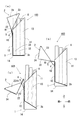
- FIG. 1A is a perspective view of the hinge lid package (closed state) according to the first embodiment as viewed from the upper front.
- FIG. 1B is a perspective view of the hinge lid package (closed state) according to the first embodiment as viewed from the upper rear side.
- the disassembled perspective view which looked at the hinge lid package which concerns on 1st Embodiment from the front upper part is shown.
- the expansion perspective view of the small box of the hinge lid package concerning a 1st embodiment is shown.
- FIG. 3 is a see-through perspective view of the hinge lid package according to the first embodiment as viewed from the front upper part, and shows an open / closed state of the hinge lid package.
- FIG. 4 is a see-through perspective view of the hinge lid package according to the first embodiment as viewed from the lower rear, and shows an open / closed state of the hinge lid package.
- FIG. 5 is a perspective view of the hinge lid package according to the first embodiment as viewed from the side, and shows an open / closed state of the hinge lid package.
- FIG. 6 is a longitudinal sectional view of the hinge lid package according to the first embodiment, and shows an open / closed state of the hinge lid package.
- FIG. 7A shows a blank of the hinge lid package according to the first embodiment (1).
- FIG. 7B shows a blank of the hinge lid package according to the first embodiment (2).
- FIG. 8A is a perspective view of the package according to the second embodiment as seen from the front upper part, and shows a closed state of the package.
- FIG. 8B is a see-through perspective view of the package according to the second embodiment as seen from the rear lower part, and shows a closed state of the package.
- FIG. 8C is a see-through perspective view of the package according to the second embodiment as viewed from the front upper part, and shows an open state of the package.
- FIG. 8D is a perspective view of the package according to the second embodiment as seen from the lower rear part, and shows the open state of the package.
- FIG. 9A shows an exploded perspective view of the package according to the second embodiment as viewed from the front upper part.
- FIG. 9B is an enlarged perspective view of a small box of the package according to the second embodiment, showing a state in which the connecting portion is bent.
- FIG. 9A shows an exploded perspective view of the package according to the second embodiment as viewed from the front upper part.
- FIG. 9B is an enlarged perspective view of a small box of the package according to the second embodiment, showing a state in which the connecting portion is bent.
- FIG. 9C is an enlarged perspective view of a small box of the package according to the second embodiment, showing a state where the connection portion is widened.
- FIG. 9D is a small box of the package according to the second embodiment, and shows an enlarged perspective view before cigarette accommodation.
- FIG. 9E is a small box of a package according to the second embodiment, and shows an enlarged perspective view after cigarette accommodation.
- FIG. 9F shows an AA cross-sectional view of FIG. 9E.
- FIG. 10A shows a package body and a lid blank among the packages according to the second embodiment.
- FIG. 10B shows a small box blank in the package according to the second embodiment.
- FIG. 11 is a perspective view of the package according to the second embodiment as seen from the front upper part, and shows the open / closed state of the package.
- FIG. 12 is a perspective view of the package according to the second embodiment as seen from the front lower part, and shows the open / closed state of the package.
- FIG. 13 is a see-through perspective view of the package according to the second embodiment as viewed from the rear lower part, and shows the open / closed state of the package.
- FIG. 14 is a perspective view of the package according to the second embodiment as viewed from the side, and shows the open / closed state of the package.
- FIG. 15A shows an operation explanatory view (1) of the package according to the second embodiment.
- FIG. 15B shows an operation explanatory diagram (2) of the package according to the second embodiment.
- FIG. 15A shows an operation explanatory view (1) of the package according to the second embodiment.
- FIG. 15B shows an operation explanatory diagram (2) of the package according to the second embodiment.
- FIG. 16 is a see-through perspective view of the package according to the first modification when viewed from the side, and shows an open / closed state of the hinge lid package.
- FIG. 17 shows the perspective view which looked at the hinge lid package (closed state) which concerns on the modification 2 from the back upper part.
- the object to be accommodated in the hinge lid package to which the present invention is applied is not limited to a specific object, but here, a case where a tobacco product such as a filter cigarette or a double-cut cigarette is accommodated in the package will be described as an example. Further, the materials, shapes, relative arrangements, and the like of the components described in the present embodiment are not intended to limit the technical scope of the invention only to those unless otherwise specified. .
- a hinge lid package (hereinafter simply referred to as “package”) 101 is a so-called hinge-lid box type package having a substantially rectangular parallelepiped shape.
- the package 101 is moved up and down in conjunction with opening and closing of the lid 2, and a lid 2 as a lid that is pivotally connected to the package body 1 via a first hinge H 1.
- the main structure includes a small box 3 as an elevating part, a connecting plate 4 as a connecting part that connects the lid 2 and the small box 3, and a tongue-like piece 5 as an auxiliary part that assists in raising and lowering the connecting plate 4.
- the front side of the package 100a is defined as “front” and the back side is defined as “rear” unless otherwise specified.
- the lid side of the package 100a is defined as “upper”, and the opposite side (the bottom side of the package) is defined as “lower”.
- the side wall side of the package 100a is defined as "side” or "lateral direction”.
- the package 101 according to the first embodiment can be made of, for example, paper material or resin, but is not limited thereto.
- the package body 1 accommodates the cigarette 6 and is a box having a rectangular parallelepiped shape whose upper end side is cut obliquely.
- the package body 1 has a front wall 11 of the package body, a rear wall 12 of the package body, a side wall 13 of the package body, and a lower wall 14 of the package body.
- the front wall 11 of the package body and the rear wall 12 of the package body are each rectangular, and the front wall 11 of the package body is a rectangle whose height is longer than that of the rear wall 12 of the package body. Opposite the wall 12.
- the side wall 13 of the pair of package bodies is connected to both side edges of the front wall 11 of the package body and the rear wall 12 of the package body, and has a trapezoidal shape in which the upper end of the rectangle is a hypotenuse. That is, the upper edge 131 of the side wall 13 of the package body is inclined so as to connect the upper end of the front wall 11 of the package body and the upper end of the rear wall 12 of the package body.
- the lower wall 14 of the package body has a rectangular shape and is connected to the lower end of the front wall 11 of the package body and the rear wall 12 of the package body.
- a first hinge H1, a tongue-like piece 5, a second hinge H2, and a cut 7 are formed on the rear wall 12 of the package body.
- the first hinge H1 is formed at the boundary between the rear wall 12 of the package main body and the rear wall 22 of the lid, and extends between the rear portions so that the rear wall 12 and the lid 2 of the package main body can rotate relative to each other. It is connected.
- the tongue-like piece 5 is formed downward from the vicinity of the center of the first hinge H1.
- the tongue-like piece 5 is formed by cutting out the rear wall 12 of the package body in a U shape near the center of the first hinge H1.
- the tongue-like piece 5 is connected to the rear wall 22 of the lid, and rotates in conjunction with opening and closing of the lid 2 so that the tip moves up and down.
- the inner surface of the tongue-like piece 5 is in contact with the outer surface of the connecting plate 4. Therefore, when the tongue-like piece 5 rotates in conjunction with the opening and closing of the lid 2, the connecting plate 4 in contact with the tongue-like piece 5 also moves up and down in conjunction with the movement of the tongue-like piece 5.
- the tongue-like piece 5 of the present embodiment has a curved lower end edge.
- the shape of the tongue-like piece 5 is not particularly limited, and may be, for example, a rectangular shape.
- the second hinge H2 extends below the first hinge H1 and the tongue piece 5 and between the rear portions.
- the second hinge H2 functions as one of the pivot shafts of the lid 2 and escapes the first hinge H1 rearward when the lid 2 is opened and closed.
- the notch 7 is formed from the first hinge H1 to the second hinge H2 in the corner formed between the rear wall of the package body and the side wall 13 of the package body (see, for example, FIG. 2A).
- the notch 7 allows the first hinge H1 to escape backward together with the second hinge H2 when the lid 2 is opened and closed. Further, the notch 7 has a function of increasing the opening degree of the lid 2.
- the package body 1 configured as described above has an opening at the upper end.
- the lid 2 is joined (coupled) to the rear edge of the opening via the first hinge H1 so as to be rotatable (turnable).
- the lid 2 covers the opening of the package body 1.
- the lid 2 has a rectangular lid rear wall 22 connected to the first hinge H1, a rectangular lid upper wall 24 connected to be orthogonal to the lid rear wall 22, and a lid upper wall 24. And a pair of triangular lid side walls 23 connected orthogonally to each other.
- the side walls 23 of the lid are connected to the respective side edges of the rear wall 22 of the lid and the upper wall 24 of the lid.
- the lid 2 when the lid 2 is in the closed state, the oblique side of the side wall 23 of the lid, that is, the inclined lower edge 231 and the inclined side of the side wall 13 of the package body, that is, the inclined upper edge 131 are aligned. Further, the front side edge 241 of the upper wall 24 of the lid matches the upper end edge 111 of the front wall 11 of the package body. As a result, the opening of the package body 1 is covered with the lid 2, and the interior of the package body 1 becomes a closed space. Further, in the present embodiment, a lid claw 25 that slightly protrudes downward is formed near the front edge and near the center of the inner surface of the upper wall 24 of the lid. The lid claw 25 engages with the upper edge 111 of the front wall 11 of the package body when the lid 2 is closed. Thereby, the closed state of the lid 2 is maintained.
- the connecting plate 4 connects the lid 2 and the small box 3 and moves the small box 3 up and down in conjunction with opening and closing of the lid 2.
- the connection plate 4 is a rectangular plate, and one end is connected to the inner surface of the rear wall 22 of the lid, and the other end is connected to the rear wall 312 of the rear small box 33.
- the connecting plate 4 is formed with a linear fold 41 extending laterally above the center in the vertical direction. More specifically, the bent portion 41 is formed at a position that matches the lower edge of the tongue-like piece 5.
- the connecting plate 4 is planar when the lid 2 is closed. On the other hand, when the lid 2 is in the open state, the connecting plate 4 is bent at the folding portion 41 so that the lid 2 falls backward.
- the connection plate 4 is comprised with a flexible member, the connection plate 4 can bend. In this case, the folding part 41 can be omitted.
- the small box 3 includes a front small box 31, a central small box 32, and a rear small box 33, and the small boxes 3 are connected to each other in the front-rear direction via the connection portion 8. ing.
- Each small box 3 accommodates the cigarettes 6 in a row so that the cigarettes 6 are connected in the horizontal direction, and moves up and down in conjunction with opening and closing of the lid 2.
- the front small box 31 is located on the front wall 11 side of the package body and accommodates seven cigarettes in a row.
- the rear small box 33 is located on the rear wall 12 side of the package main body, and accommodates seven cigarettes in a row like the front small box 31.
- the central small box 32 is sandwiched between the front small box 31 and the rear small box 33 and accommodates six cigarettes in a row.
- Each small box 3 has a small box front wall 311, a small box rear wall 312, a small box side wall 313, and a small box lower wall 314.
- the front wall 311 of the small box and the rear wall 312 of the small box are each a horizontally-long rectangle, have substantially the same area, and face each other.
- the side wall 313 of the small box is connected to both side edges of the front wall 311 of the small box and the rear wall 312 of the small box, and is a vertically long rectangle.
- the lower wall 314 of the small box is rectangular and is connected to the lower edge of the front wall 311 of the small box and the rear wall 312 of the small box.
- the rear wall 312 of the rear small box 33 is connected to a connecting plate 4 that extends upward and is formed integrally with the rear wall 312.
- a small piece 9 for restricting the movement of the cigarette 6 is formed on the side wall 313 side of one small box on the front wall 311 of the small box.
- the small piece 9 has a width that is about half the width of the front wall 311 of the small box, and protrudes inside the small box.
- the small piece 9 is formed with a bent portion 91 in the width direction, and the small piece is bent around the bent portion 91 and functions as an elastic member. And the small piece 9 controls the movement of the cigarette 6 by pressing the cigarette 6 accommodated in the small box 3 inside.
- On the rear wall 312 of the small box a similar small piece 9 is formed on the side wall 313 side of the other small box.
- the connection portion 8 includes a first connection portion 81 that connects the front wall 11 of the package body and the front small box 31, a second connection portion 82 that connects the front small box 31 and the central small box 32, and the central small box 32.
- a third connecting portion 83 that connects the rear small box 33 is included.
- the first connection portion 81 is connected to the inner surface of the front wall 11 of the package body, and has a plate-like front connection portion 811 parallel to the front wall 11 of the package body, and an upper end edge of the front wall 311 of the front small box 31.
- the lower end edge is connected to the edge, the lower end edge is connected to the lower end edge of the front connection portion 811, and the rear connection portion 812 parallel to the front wall 311 of the front small box 31 is provided.
- a lower part of the rear connection part 812 is formed by a foldable folding part 813. Therefore, the length in the vertical direction of the rear connection portion 812 varies depending on the state of the folding portion 813.
- the folding portion 813 includes a first mountain fold portion 814, a first small plate 815, a second mountain fold portion 816, a second small plate 817, and a valley fold portion 818. Changes.
- the front connection portion 811 is a glue margin connected to the inner surface of the front wall 11 of the package body, and has a vertical length necessary to function as a glue margin. The length in the vertical direction of the rear connection portion 812 is longer than the length in the vertical direction of the front connection portion 811.
- the rear connection portion 812 is longer in the vertical direction in the extended state than the folded portion 813 is contracted. Therefore, the front small box 31 connected to the rear connection portion 812 of the first connection portion 81 can also move in the vertical direction, in other words, can move up and down.
- the second connection part 82 and the third connection part 83 have the same configuration.
- the third connecting portion 83 will be described as an example.
- the upper end edge of the front connecting portion 831 is different from the first connecting portion 81 in that it is connected to the upper end edge of the rear wall 312 of the central small box 32. Are the same.
- the length of the rear connection portion 832 in the vertical direction is the same as the length of the front connection portion 831 in the vertical direction.
- the rear small box 33 connected to the rear connection portion 832 of the third connection portion 83 can also move in the vertical direction, in other words, can move up and down.
- the package 101 is formed by folding and joining the first blank B1 for forming the package body 1 and the lid 2 and the second blank B2 for forming the connecting plate 4 and the small box 3. be able to.
- FIG. 7A shows the first blank B1
- FIG. 7B shows the second blank B2.
- a paper material such as card paper or Manila cardboard, or a resin such as a plastic sheet can be used, but is not limited thereto.
- the description of the blank the description will be made with reference to the vertical direction of the drawing.
- the first blank B ⁇ b> 1 has a main body area R ⁇ b> 1 that becomes the package main body 1 and a lid area R ⁇ b> 2 that becomes the lid 2.
- the main body section R1 has a front wall panel P1 of the main body that becomes the front wall 11 of the package main body, and side wall panels P2, P2 is connected.
- the lower wall (bottom plate) panel P3 of the main body which becomes the lower wall 14 of the package main body, is connected to the upper edge (the upper edge in FIG. 7A) of the front wall panel P1 of the main body.
- the lower wall panel P3 of the main body is connected to the rear wall panel P4 of the main body which is located on the opposite side of the front wall panel P1 of the main body and becomes the rear wall 12 of the package main body.
- Inner side flaps P5 and P5 of the main body which become the side wall 13 of the package main body are connected to both side edges of the rear wall panel P4 of the main body.
- an inner bottom flap P6 of the main body is connected to the lower edge of the inner side flaps P5 and P5 of the main body, and the inner bottom flap P6 of the main body is overlapped with the lower wall panel P3 of the main body, and the lower wall of the package main body. 14 reinforcements.
- a second hinge line L2 serving as the second hinge H2 is formed on the rear wall panel P4 of the main body. Further, on both edges of the rear wall panel P4 of the main body, a linear notch C1 that forms a cut 7 from an upper edge (a first hinge line L1 described later) to a second hinge line L2 is formed.
- the lid area R2 has a rear wall panel P7 of the lid that becomes the rear wall 22 of the lid, and the lower edge of the rear wall panel P7 of the lid is the main body via the first hinge line L1 that becomes the first hinge H1. It is connected with the rear wall panel P4 of the main body of the area R1. Further, a U-shaped notch C2 that forms the tongue-like piece 5 is formed in the rear wall panel P7 of the lid. Further, the upper wall panel P8 of the lid, which becomes the upper wall 24 of the lid, is connected to the upper edge of the rear wall panel P7 of the lid in the lid area R2. On both edges of the upper wall panel P8 of the lid, side wall panels P9 and P9 of the lid serving as the side wall of the lid are connected.
- inner side flaps P10 of the lid which are part of the side wall 23 of the lid, are connected to both side edges of the rear wall panel P7 of the lid. Then, the inner side flap P10 of the lid is superimposed on the side wall panel P9 of the lid, and the side wall 23 of the lid is reinforced.
- an inner top flap P11 of the lid that is folded back to reinforce the upper wall 24 of the lid is connected to the upper edge of the upper wall panel P8 of the lid.
- the inner bottom flap P11 of the lid is formed with an inverted U-shaped cutout C3 that becomes the claw 25 of the lid.
- the second blank B2 includes the connection regions R3-1, R3-2, and R3-3 that become the connection portion 8, and the small box regions R4-1, R4-2, and R4- that become the small box 3. 3. It has a connection region R5 to be a connection plate 4. These regions are connected in the order of connection region R3-1, small box region R4-1, connection region R3-2, small box region R4-2, connection region R3-3, small box region R4-3, and connection region R5. ing.
- connection regions R3-1, R3-2, and R3-3 include a front connection panel P21 that becomes the front connection portion 811, a first small panel P22 that becomes the first small plate 815, and a second small plate that becomes the second small plate 817.
- P23 has a rear connection panel P24 to be the rear connection portion 812.
- the first small panel P22 is connected to the upper edge of the front connection panel P21
- the second small panel P23 is connected to the upper edge of the first small panel P22
- the rear connection panel P24 is connected to the upper edge of the second small panel P23.
- a small box region R4-1 is connected to the connection region R3-1 configured as described above.
- the front connection panel P21 serving as the front connection part 811 of the first connection part 81 is formed to have a shorter vertical length than the front connection panel P21 serving as the front connection part 811 of the second connection part 82 and the third connection part 83. Has been.
- the small box regions R4-1, R4-2, and R4-3 have a small box front wall panel P25 that becomes the small box front wall 311.
- a notch C4 to be a small piece 9 is formed on the front wall panel P25 of the small box.
- side wall panels P26 and P26 of the small box that become the side wall 313 of the small box are connected to both side edges of the front wall panel P25 of the small box.
- the lower wall panel P27 of the small box that becomes the lower wall 314 of the small box is connected to the upper edge of the front wall panel P25 of the small box.
- a rear wall panel P28 of the small box that is the rear wall 312 of the small box is connected to the upper edge of the lower wall panel P27 of the small box.
- a notch C4 to be a small piece 9 is formed in the rear wall panel P28 of the small box.
- inner side flaps P29 and P29 of the small box for reinforcing the side wall 313 of the small box are connected to both side edges of the rear wall panel P28 of the small box.
- an inner bottom flap P30 of the small box is connected to the lower edge of the inner side flaps P29, P29 of the small box, and the inner bottom flap P30 of the small box is overlapped with the lower wall panel P27 of the small box, Reinforce the lower wall 314 of the box.
- connection region R5 has a connection panel P31 that becomes the connection plate 4.
- the connection panel P31 is formed with a line L3 that becomes a linear bent portion 41.
- the package 101 including the package body 1 and the lid 2 as shown in FIGS. 1 to 6 is formed.
- the inner bottom flap P6 of the main body is folded on each folding line, and the inner bottom flap P5 of the main body is overlaid on the lower wall panel P3 of the main body.
- the package body 1 is formed.
- the inner side flap P10 of the lid is bonded to the side wall panel P9 of the lid, and the inner top flap P11 of the lid is attached to the upper wall panel P8 of the lid.
- the lid 3 is molded by being overlaid.
- the second blank B2 described above is folded at the folding line indicated by the broken line in FIG. 7B.
- the small box 3 the connecting portion 8, and the connecting plate 4 as shown in FIGS. 1 to 6 are formed.
- the connection portion 8 is formed by being folded at each folding line.
- the small box inner bottom flap P30 is overlaid on the small box lower wall panel P27, and the small box inner side flap P29 is the small box.
- the small box 3 is formed by being adhered to the side wall panel P26.
- the upper part of the connecting plate 4 is bonded to the lid 2, and the front connection part 811 of the first connection part 81 is connected to the front wall 12 of the package body, whereby the package 101 is molded. Is done.
- Opening and closing action >> Next, the opening / closing operation
- the package 101 covers the opening of the package body 1 when the lid 2 is closed.
- the package 101 is normally in a closed state. In the closed state, the lid claw 25 is engaged with the upper edge of the front wall 11 of the package body, and the opening and closing of the lid 2 is restricted.
- the lid 2 when the cigarette 6 accommodated in the package 101 is taken out, the lid 2 is opened. Specifically, the engagement between the claw 25 of the lid and the upper edge of the front wall 11 of the package body is released, and the lid 2 starts to rotate (FIGS. 3A, 4A, and 5). a) and FIG. 6 (a)).
- the package 101 includes a first hinge H1 and a second hinge H2, and the lid 2 rotates about both the first hinge H1 and the second hinge H2. As shown in FIGS. 3 (a), 4 (a), 5 (a), and 6 (a), the lid 2 pivots around the second hinge H2 rather than the first hinge H1 at the beginning of rotation. To turn. In conjunction with the rotation of the lid 2, the connecting plate 4 is gradually pulled up and starts to rise.
- the tongue-like piece 5 starts to rotate around the first hinge H1 in conjunction with the lid 2. At that time, the tongue-like piece 5 raises the connecting plate 4 while pushing the connecting plate 4 forward.
- the first hinge H1 gradually moves backward due to the reaction force of the force that the tongue-like piece 5 pushes the connecting plate 4 forward.
- the connecting plate 4 is pulled up by the lid 2 and pushed up by the tongue-shaped piece 5.
- the connecting plate 4 starts to rise in conjunction with the lid 2, and the connecting plate 4 starts to rise, so that the folding portion 813 of the rear connecting portion 812 of the third connecting portion starts to extend.
- the rear small box 33 of the small box 3 starts to gradually rise.
- the lid 2 pivots on the first hinge H1 rather than the second hinge H2 in the rotating middle stage.
- the connecting plate 4 is further lifted and raised.
- the tongue-like piece 5 is further rotated about the first hinge H1.
- the tongue-like piece 5 raises the connecting plate 4 while pushing the connecting plate 4 forward.
- the reaction force of pushing the connecting plate 4 forward acts more strongly, and the first hinge H1 further moves rearward.
- the connecting plate 4 is pulled up by the lid 2 and further pushed up by the tongue-like piece 5.
- the folding part 813 of the rear connection part 812 of the third connection part also starts to extend.
- the central small box 32 starts to gradually rise following the rear small box 33.
- the lid 2 pivots on the first hinge H1 rather than the second hinge H2 at the end of rotation.
- the connecting plate 4 is further lifted and raised.
- the tongue-like piece 5 is further rotated about the first hinge H1. At that time, the tongue-like piece 5 raises the connecting plate 4 while pushing the connecting plate 4 forward or obliquely upward.
- the small box 3 that houses the cigarette 6 moves up and down in conjunction with the opening and closing of the lid 2. Therefore, the cigarette 6 can be lifted and lowered simply by opening and closing the lid 2, in other words, without separately performing an operation for lifting and lowering, so that the cigarette 6 can be easily taken out from the package 101.
- the package 101 according to the embodiment is provided with the tongue-like piece 5 so that the strength is improved as compared with the conventional package that lifts up in conjunction with the opening and closing of the lid, and the small box 3 is stably provided. You can go up and down.
- the load concentrates on the part connecting the lid part and the lift part.
- the tongue-like piece 5 By assisting the raising and lowering, the load is also distributed. As a result, the strength is improved and the small box 3 can be moved up and down stably. Further, by adjusting the length of the tongue-like piece 5 and the position of the bent portion 41 of the connecting plate, the moving range of the lifting / lowering can be adjusted, for example, the moving range of the lifting / lowering can be made larger than that of the conventional package. .
- the small boxes 3 are divided for each row, and the small box 3 is provided with small pieces 9. Therefore, even when the number of cigarettes 6 decreases, the movement of the cigarettes 6 can be suppressed. As a result, in the package 101 according to the first embodiment, even when the number of cigarettes 6 is reduced, the cigarettes 6 are hardly inclined, so that the cigarettes 6 are less likely to be taken out. That is, in the package 101 according to the first embodiment, the small boxes 3 that house the cigarettes 6 are moved up and down for each column, and the range of movement of the cigarettes 6 that are housed in the small boxes 3 is small. Regardless, the cigarette 6 can be easily removed from the package 101.
- the small boxes 3a are moved up and down for each row in conjunction with opening and closing of the lid 2a. Furthermore, a space
- the cigarettes 6 are not only raised for each row, but are spaced from each other in the front-rear direction. Therefore, the cigarette 6 is easier to grasp and can be taken out from the package 100a.
- the package 100a according to the second embodiment is a so-called hinge-lid box type package having a rectangular parallelepiped shape.
- the package 100a includes a package main body 1a serving as an accommodating portion, a lid 2a serving as a lid that is rotatably connected to the package main body 1a via a first hinge H1, and an ascending / descending operation that is interlocked with the opening / closing of the lid 2a.
- Main parts are a small box 3a as a part, a connecting plate 4a as a connecting part that connects the lid 2a and the small box 3a, and a tongue-like piece 5a as an auxiliary part that assists in raising and lowering the connecting plate 4a.
- the package 100a according to the second embodiment can be made of, for example, a paper material or a resin, but is not limited thereto.
- the package main body 1a accommodates the cigarette 6, and is a box having a shape in which the upper end side of the rectangular parallelepiped shape is cut out obliquely and the front is largely opened.
- the package body 1a has a front wall 11a of the package body, a rear wall 12a of the package body, a side wall 13a of the package body, and a lower wall 14a of the package body.
- the rear wall 12a of the package body is a vertically long rectangle.
- the front wall 11a of the package body is formed with a shorter height than the rear wall 12a of the package body.
- the front wall 11a of the package body and the rear wall 12a of the package body face each other.
- the side wall 13a of the pair of package bodies is connected to both side edges of the front wall 11a of the package body and the rear wall 12a of the package body, and has a shape in which the upper end of the rectangle is a curved oblique side.
- the upper end edge 131a of the side wall 13a of the package body is inclined so that the front wall 11a side of the package body is lowered.
- the lower wall 14a of the package body is rectangular and is connected to the lower end edge of the front wall 11a of the package body, the rear wall 12a of the package body, and the side wall 13a of the package body.
- the rear wall 12a of the package body is formed with a first hinge H1, a tongue-like piece 5a, a second hinge H2, and a cut 7a.
- the first hinge H1 is formed at the boundary between the rear wall 12a of the package body and the rear wall 22a of the lid, extends across the rear portion, functions as one of the pivot shafts of the lid 2a, and When opening and closing, the third hinge H3 escapes backward.
- the tongue-like piece 5a is formed downward from the vicinity of the center of the first hinge H1.
- the tongue-like piece 5a is formed by cutting out the rear wall 12a of the package body in a U-shape near the center of the first hinge H1.
- the tongue-like piece 5a is continuous with the rear wall 22a of the lid, and rotates in conjunction with the opening and closing of the lid 2a, so that the tip moves up and down. Further, the inner surface of the tongue-like piece 5a is in contact with the outer surface of the connecting plate 4a. Therefore, when the tongue-like piece 5a rotates in conjunction with the opening and closing of the lid 2a, the connecting plate 4a in contact with the tongue-like piece 5a also moves up and down in conjunction with the movement of the tongue-like piece 5a.
- the tongue-like piece 5a of the present embodiment has a curved lower end edge.
- the shape of the tongue-like piece 5a is not particularly limited, and may be a rectangular shape, for example.
- the second hinge H2 is formed below the first hinge H1 and the tongue-like piece 5a in the rear wall 12a of the package body, and extends between the rear portions.
- the second hinge H2 functions as one of the pivot shafts of the lid 2a, and escapes the first hinge H1 and the third hinge H3 rearward when the lid 2a is opened and closed.
- the notches 7a are formed at corners formed between the rear wall 12a of the package body and the side wall 13a of the package body, and at corners formed between the rear wall 22a of the lid and the side wall 23a of the lid,
- the third hinge H3 to the second hinge H2 are formed.
- the notch 7a allows the first hinge H1 and the third hinge H3 to escape backward together with the first hinge H1 and the second hinge H2 when the lid 2a is opened and closed.
- the cut 7a has a function of increasing the opening degree of the lid 2a. Note that only the cut 7a may be provided without providing the second hinge H2. In this case, when the lid 2a is opened and closed, the function of releasing the first hinge H1 and the third hinge H3 backward is inferior to that when the second hinge H2 is provided, but the package can be assembled more easily.
- the lid 2a is joined (connected) to the upper end edge of the rear wall 12a of the package main body via a first hinge H1 so as to freely rotate (turn).
- the lid 2a covers the opening of the package body 1a.
- the lid 2a includes a rectangular lid rear wall 22a connected to the first hinge H1, a lid upper wall 24a, a pair of rectangular lid side walls 23a, a lid front wall 20a, and a lid under the lid. It is a box shape provided with the wall 26a.
- the rear wall 22a of the lid faces the front wall 20a of the lid, but its area is very small compared to the front wall 20a of the lid. Therefore, the lid 2a has a box shape in which most of the rear area is opened (all areas other than the lid rear wall 22a are opened).
- a side wall 23a of the lid is formed with a semicircular cutout portion 27a for operating the lid 2a when the lid 2a is opened and closed.
- the lid 2a When the lid 2a is in the open state, the cigarette 6 can be taken in and out through the openings (upper and front) of the package body 1a.
- the lid 2a when the lid 2a is in the closed state, the lid 2a covers the region including the opening of the package body 1a and excluding the rear wall of the package body 1a.
- a third hinge H3 is formed at the boundary (the corner in the closed state) between the upper wall 24a of the lid and the rear wall 22a of the lid.
- the third hinge H3 is formed at the upper edge of the rear wall 22a of the lid and extends across the rear part.
- the third hinge H3 functions as one of the rotating shafts of the lid 2a.
- the connecting plate 4a connects the lid 2a and the small box 3a, and moves the small box 3a up and down in conjunction with opening and closing of the lid 2a.
- the connecting plate 4a is formed of a rectangular plate, one end is connected to the inner surface of the rear wall 22a and the upper wall 24a of the lid, and the other end is connected to the rear wall 312a of the rear small box 33a in the small box 3a.
- the connecting plate 4a is formed with a linear bent portion 41a extending in the lateral direction above the center in the vertical direction. More specifically, the bent portion 41a is formed at a position that matches the lower end edge (tip end edge) of the tongue-like piece 5a.
- the bent portion 41a of the connecting plate 4a is planar when the lid 2a is closed.
- the bent portion 41a of the connecting plate 4a is bent so that the lid 2a falls backward when the lid 2a is in the open state.
- the connection plate 4a can bend.
- the bent portion 41a can be omitted.
- the connection plate 4a is formed of a flexible member, the amount by which the small box 3a rises can be changed as appropriate simply by adjusting the length of the tongue-like piece 5a.
- the small box 3a includes a front small box 31a, a central small box 32a, and a rear small box 33a, and the small boxes 3a are mutually connected in the front-rear direction via the connecting portion 8a. It is lined up. Each small box 3a accommodates the cigarettes 6 in a row so that the cigarettes 6 are connected in the horizontal direction, and moves up and down in conjunction with opening and closing of the lid 2a.
- the front small box 31a is located on the front wall 11a side of the package body, and accommodates seven cigarettes in a row.
- the rear small box 33a is located on the rear wall 12a side of the package main body, and accommodates seven cigarettes in a row like the front small box 31a.
- the central small box 32a is sandwiched between the front small box 31a and the rear small box 33a and accommodates six cigarettes in a row.
- Each small box 3a has a small box front wall 311a, a small box rear wall 312a, a small box side wall 313a, and a small box lower wall 314a.
- the front wall 311a of the small box and the rear wall 312a of the small box are each a horizontally long rectangle and face each other.
- the height dimension of the rear wall 312a of the small box is formed higher than the front wall 311a of the small box.
- the height of the rear wall 312a of the small box is the same as the height of the second connection part 82a or the third connection part 83a. It is formed higher than the front wall 311a of the small box.
- the rear wall 312a of the rear small box 33a is continuous with the connection plate 4a, and the boundary with the connection plate 4a is not clear, but has the same height as the rear wall 312a of the front small box 31a and the central small box 32a. is doing.
- the side wall 313a of the small box is a vertically long rectangle, and is connected to both side edges of the front wall 311a of the small box and the rear wall 312a of the small box.
- the lower wall 314a of the small box is rectangular, and is connected to the lower end edge of the front wall 311a of the small box, the rear wall 312a of the small box, and the side wall 313a of the small box.
- the rear wall 312a of the rear small box 33a is connected to a connecting plate 4a that extends upward and is formed integrally with the rear wall. Further, a first connection portion 81a formed integrally with the front wall is connected to the front wall 311a of the front small box 31a.
- the connection portion 8a includes a first connection portion 81a that connects the front wall 11a of the package body and the front small box 31a, a second connection portion 82a that connects the front small box 31a and the central small box 32a, and a central small box 32a.
- a third connecting portion 83a that connects the rear small box 33a is included.
- the 1st connection part 81a is a rectangular plate connected to the upper end edge of the front wall 311a of the front small box 31a, and is continued to the front wall 11a of the package body.
- the first connecting portion 81a is formed with a bent portion 811a extending in the lateral direction near the center in the vertical direction.
- the front small box 31a can fall forward because the folding part 811a is at a position higher than the upper edge of the front wall 11a.
- a connection region 812a below the bent portion 811a is connected to the inner surface of the front wall 11a of the package body.
- the upper end edge of the non-connection region 813a above the bent portion 811a is connected to the upper end edge of the front wall 311a of the front small box 31a.
- the second connecting portion 82a is formed of an elongated small plate and is continuous with the upper end edge of the rear wall of the front small box 31a and the upper end edge of the front wall 311a of the central small box 32a.
- the third connection portion 83a is formed of a small and narrow plate, and is continuous with the upper end edge of the rear wall 312a of the central small box 32a and the upper end edge of the front wall 311a of the rear small box 33a.
- connection portion 8a first connection portion 81a, second connection portion 82a, third connection portion 83a
- the first connection portion 81a is located in front of the front small box 31.
- the second connecting portion 82a is folded on the rear wall 312a of the front small box 31a
- the third connecting portion 83a is folded on the rear wall 312a of the central small box 32a.
- the height dimension of the small box rear wall 312a is higher than the front wall 311a of the small box by the length corresponding to the height dimension of the second connection part 82a and the third connection part 83a. Therefore, in a state where the connecting portion 8a is completely bent, the small boxes 3a approach each other, and the small boxes 3a are at the same height position.
- a small piece 9a for restricting the movement of the cigarette 6 is provided on the side wall 313a side of one small box (see FIG. 9D to FIG. 9E). It is formed on the left side when viewed from the front.
- the small piece 9a has a length that is about half of the lateral length of the front wall 311a of the small box, and protrudes inside the small box.
- the small piece 9a is formed by cutting out the front wall 311a of the small box into a horizontally long U-shape.
- the small piece 9a is formed with a folded portion 91a extending in the horizontal direction.
- the small piece 9a is curved inward with respect to the bent portion 91a and functions as an elastic member. And the small piece 9a regulates the movement of the cigarette 6 by pressing the cigarette 6 accommodated in the small box 3a.
- On the rear wall 312a of the small box a similar small piece 9a is formed on the side wall 313a side (right side when viewed from the front) of the other small box.
- the small piece 9a in the small box is divided into a front wall 311a of the small box and a rear wall 312a of the small box, and each extends to about half of the lateral length.
- the strength of the small box 3a is improved as compared with the case where the small piece 9a extends from only one front wall 311a of the small box or only the rear wall 312a of the small box from one end to the other end in the lateral direction of the small box 3a. be able to.
- the package 100a can be formed by folding and joining the first blank B1a for forming the package body 1a and the lid 2a and the second blank B2a for forming the connecting plate 4a and the small box 3a.
- FIG. 10A shows the first blank B1a
- FIG. 10B shows the second blank B2a.
- a paper material such as card paper or Manila cardboard, or a resin such as a plastic sheet can be used, but is not limited thereto.
- the description of the blank the description will be made with reference to the vertical direction of the drawing.
- the first blank B1a has a main body area R1a that becomes the package main body 1a and a lid area R2a that becomes the lid 2a.
- the main body section R1a has a front wall panel P1a of the main body which becomes the front wall 11a of the package main body, and side wall panels P2a of the main body which become the side walls 13a of the package main body on both side edges of the front wall panel P1a of the main body. P2a is connected.
- a lower wall (bottom plate) panel P3a of the main body which becomes the lower wall 14a of the package main body, is connected to the upper edge of the front wall panel P1a of the main body.
- an R portion composed of a plurality of folding lines that are R is formed between the front wall panel P1a of the main body and the lower wall panel P3a of the main body.
- the lower wall panel P3a of the main body is connected to the rear wall panel P4a of the main body that is located on the opposite side of the front wall panel P1a of the main body and serves as the rear wall 12a of the package main body.
- Inner side flaps P5a and P5a of the main body which become the side wall 13a of the package main body are connected to both side edges of the rear wall panel P4a of the main body.
- an inner bottom flap P6a of the main body is connected to the lower edge of the inner side flaps P5a and P5a of the main body, and the inner bottom flap P6a of the main body is overlapped with the lower wall panel P3a of the main body, and the lower wall of the package main body.
- Reinforce 14a Further, the rear wall panel P4a of the main body is formed with a second hinge line L2a that becomes the second hinge H2 and a first hinge line L1a that becomes the first hinge H1.
- a linear notch C1a is formed which extends from the third hinge line L3a to the second hinge line L2a of the rear wall panel P7a of the lid and becomes a cut 7a.
- a U-shaped notch C2a that forms the tongue-like piece 5a is formed in the rear wall panel P4a of the main body.
- the lid area R2a has a rear wall panel P7a of the lid that becomes the rear wall 22a of the lid.
- the upper wall panel P8a of the lid serving as the upper wall 24a of the lid is connected to the upper edge of the rear wall panel P7a of the lid via the third hinge line L3a serving as the third hinge H3.
- Inner side flaps P9a and P9a of the lid, which are part of the side wall 23a of the lid, are connected to both side edges of the upper wall panel P8a of the lid.
- a lid front wall panel P10a which becomes the lid front wall 20a, is connected to the upper edge of the lid upper wall panel P8a.
- the side wall panel P11a of the lid used as the side wall 23a of the lid is connected to both side edges of the front wall panel P10a of the lid.
- the side wall panel P11a of the lid is formed with a circular cutout C5a that becomes the operation portion 27a.
- the side wall panel P11a of the lid is folded back by a folding line extending in the vertical direction near the center in the horizontal direction (the center of the circle), and the inner side flap P9a of the lid and the inner side flap P13a of the lid are sandwiched therebetween, and the side wall 23a of the lid is sandwiched.
- the lower wall panel P12a of the lid which becomes the lower wall 26a of the lid is connected to the upper edge of the front wall panel P10a of the lid.
- an R portion including a plurality of folding lines that are R is formed between the front wall panel P10a of the lid and the lower wall panel P12a of the lid.
- An inner side flap P13a of the lid is connected to both side edges of the lower wall panel P12a of the lid.
- an inner bottom flap P14a of the lid that is folded back to reinforce the lower wall 26a of the lid is connected to the upper edge of the lower wall panel P12a of the lid.
- the second blank B2a includes connection regions R3a-1, R3a-2, R3a-3 to be the connection portion 8a, and small box regions R4a-1, R4a-2, R4a- to be the small box 3a. 3. It has the connection area
- the connection region R3a-1 has a first connection panel P21a that becomes the first connection portion 81a.
- the first connection panel P ⁇ b> 21 a is a horizontally long rectangle, and extends in the horizontal direction near the center in the vertical direction, and a fold line serving as a fold portion 811 a is formed.
- the area below the folding line is connected to the inner surface of the front wall 11a of the package body, and the edge of the area above the folding line is connected to the upper edge of the front wall 311a of the front small box 31a.
- connection regions R3a-2 and R3a-3 have second connection panels P22a and P22a that become the second connection part 82a and the third connection part 83a.
- the small box regions R4a-1, R4a-2, and R4a-3 have a small box front wall panel P25a that becomes the small box front wall 311a.
- the front wall panel P25a of the small box is formed with a notch C4a that becomes a small piece 9a.
- side wall panels P26a and P26a of the small box that become the side wall 313a of the small box are connected to both side edges of the front wall panel P25a of the small box.
- the lower wall panel P27a of the small box that becomes the lower wall 314a of the small box is connected to the upper edge of the front wall panel P25a of the small box.
- the rear wall panel P28a of the small box that becomes the rear wall 312a of the small box continues to the upper edge of the lower wall panel P27a of the small box.
- a cutout C4a to be a small piece 9a is formed in the rear wall panel P28a of the small box.
- inner side flaps P29a and P29a of the small box for reinforcing the side wall 313a of the small box are connected to both side edges of the rear wall panel P28a of the small box.
- the inner bottom flaps P30a of the small boxes are connected to the lower edges of the inner side flaps P29a and P29a of the small boxes, and the inner bottom flaps P30a of the small boxes are overlapped with the lower wall panel P27a of the small boxes.
- the lower wall 314a of the box is reinforced.
- connection region R5a has a connection panel P31a that becomes the connection plate 4a.
- connection panel P31a a line L4a serving as a linear bent portion 41a is formed.
- 1st blank B1a mentioned above is each folded in the folding line shown with the broken line in FIG. 10A.
- a package 100a including the package body 1a and the lid 2a as shown in FIGS. 8A to 8D and FIG. 9 is formed.
- the inner bottom flap P6a of the main body is overlaid on the lower wall panel P3a of the main body, and the inner side flap P5a of the main body is bonded to the side wall panel P2a of the main body.
- the package body 1a is molded.
- the lid area R2a of the first blank B1a is folded at each folding line, and the inner side flap P9a of the lid and the inner side flap P13a of the lid are sandwiched and adhered to the side wall panel P11a of the lid, and the inner part of the lid
- the lid 2a is formed by overlapping the bottom flap P14a on the lower wall panel P12a of the lid.
- the second blank B2a described above is folded at the folding line indicated by the broken line in FIG. 10B.
- the small box 3a, the connecting portion 8a, and the connecting plate 4a as shown in FIGS. 9A to 9F are formed.
- the connection portions 8a first connection portion 81a, second connection portion 82a, and third connection portion 83a are folded by folding lines. ) Is formed.
- the small box inner bottom flap P30a is overlapped with the small box lower wall panel P27a, and the small box inner side flap P29a is small.
- the small box 3a is formed by being adhered to the side wall panel P26a.
- the upper portion of the connecting plate 4a is bonded to the lid 2a, and the front connection portion 811a of the first connection portion 81a is connected to the front wall panel 11a of the package body, thereby forming the package 100a. Is done.
- FIG. 15A and FIG. 15B are diagrams for explaining the operation of the package according to the second embodiment.
- the lid 2a When the lid 2a is in the closed state, the lid 2a covers a surface other than the back of the package body 1a. When it is not necessary to take out the cigarette 6 accommodated in the package 100a, the package 100a is normally in a closed state. In the closed state, the lower wall 26a of the lid and the lower wall of the package body 1a are in contact with each other, and the opening and closing of the lid 2a is restricted.
- the lid 2a When taking out the cigarette 6 accommodated in the package 100a, the lid 2a is opened. Specifically, the surface contact state between the lower wall 26a of the lid and the lower wall 14a of the package body is released, and the lid 2a starts to rotate (FIGS. 11B, 12B, and 13B). 14B, FIG. 15A (b)).
- the package 100a includes a first hinge H1, a second hinge H2, and a third hinge H3, and the lid 2a rotates around the first hinge H1, the second hinge H2, and the third hinge H3.
- FIG. 15A (b) in the early stage of rotation, the lid 2a starts to rotate mainly about the third hinge H3.
- the tongue-like piece 5a starts to rotate around the first hinge H1 in conjunction with the lid 2a. At that time, the tongue-like piece 5a raises the connecting plate 4a while pushing the connecting plate 4a forward. Further, when the lid 2a is in the open state, a force acts backward, so that the third hinge H3 gradually moves backward in conjunction with the rotation of the lid 2a.
- the lid 2a In conjunction with the rotation, the connecting plate 4a is gradually lifted and raised. Further, in conjunction with the lid 2a, the tongue-like piece 5a further rotates about the first hinge H1. At that time, the tongue-like piece 5a further raises the connecting plate 4a while pushing the connecting plate 4a forward. The first hinge H1 moves rearward due to the reaction force of the force that the tongue-like piece 5a pushes the connecting plate 4a forward. Further, the third hinge H3 moves further rearward. The connecting plate 4a is pulled up by the lid 2a and pushed up by the tongue-like piece 5a.
- the connecting plate 4a further moves up in conjunction with the lid 2a.
- the rear small box 33a, the central small box 32a, and the front small box 31a rise.
- the connecting plate 4a is raised, the rear small box 33a is raised, and the third connecting portion 83a that connects the rear small box 33a and the central small box 32a is in a horizontal state or a state close thereto.
- the central small box 32a is also raised next, and when the central small box 32a is raised, the second connecting portion 82a that connects the central small box 32a and the front small box 31a is in a horizontal state or It becomes a state close to this.
- the front wall 11a of the package body is formed shorter in height than the rear wall 12a of the package body.
- the height dimension of the front wall 11a of the package body is designed to be about half the height dimension of the small box 3a. Therefore, movement in the front-rear direction is restricted at the lower part of the small box 3a, but movement in the front-rear direction is allowed at the upper part.
- the front wall 11a of the package body does not exist at the height position of the second connection part 82a or the third connection part 83a, and the movement of the small box 3a in the front-rear direction is allowed.
- the second connection part 82a and the third connection part 83a are in a horizontal state or a state close thereto.
- the interval between the small boxes 3a is narrow at the bottom and gradually widens upward.
- the lid 2a is The first hinge H1 is pivoted about the second hinge H2.
- the connecting plate 4a is further raised.
- the tongue-like piece 5a further rotates about the first hinge H1.
- the tongue-like piece 5a raises the connecting plate 4a while pushing the connecting plate 4a forward.
- the reaction force of pushing the connecting plate 4a forward gradually decreases, and the downward force applied to open the lid 2a raises the connecting plate 4a with the first hinge H1 as a fulcrum.
- the connecting plate 4a is pulled up to the lid 2a and further pushed up by the tongue-shaped piece 5a.
- the rear small box 33a, the central small box 32a, and the front small box 31a are further raised.
- the rear small box 33a rises highest, then the central small box 32a rises high, and then the front small box 31a rises.
- the force for restricting the movement in the front-rear direction in the upper part of the small box 3a is further weakened, and the interval between the small boxes 3a is further widened. .
- the movement in the front-rear direction is restricted as described above.
- the interval between the small boxes 3a is gradually narrowed further upward while the lower portion remains narrow.
- the cigarette 6 accommodated in the small box 3a spreads in a fan shape when viewed from the side.
- the small box 3a that houses the cigarette 6 moves up and down in conjunction with the opening and closing of the lid 2a. Therefore, the cigarette 6 can be lifted and lowered easily by simply opening and closing the lid 2a, in other words, without separately performing an operation for lifting and lowering, so that the cigarette 6 can be easily taken out from the package 100a.
- the package 100a according to the embodiment includes the tongue-like piece 5a, so that the strength is improved and the small box 3a can be stably provided as compared with the conventional package that lifts up in conjunction with opening and closing of the lid. You can go up and down.
- the moving range of the lifting / lowering can be adjusted, for example, the moving range of the lifting / lowering can be made larger than that of the conventional package. it can.
- the package 100a can form a space
- the cigarettes 6 are not only raised, but are spaced from each other in the front-rear direction. Therefore, the cigarette 6 is easier to grasp and can be taken out from the package 100a.
- the small boxes 3a are divided for each row, and the small boxes 3a are provided with small pieces 9a. Therefore, even when the number of cigarettes 6 decreases, the movement of the cigarettes 6 can be suppressed. As a result, even when the number of cigarettes 6 is reduced, it is difficult for the cigarettes 6 to be taken out because the cigarettes 6 are inclined. Further, by connecting the upper edges of the small box 3a, the spread of the small box in the front-rear direction can be regulated. As a result, it is possible to further improve the aesthetics when the small box 3a is expanded in a side view fan shape.
- FIG. 16 shows a package 103 according to the first modification.
- the package 103 according to the modified example 1 is configured by an elevating plate 3b instead of the small box 3.
- the lift plate 3 b moves up and down in conjunction with the rotation of the lid 2.
- the elevating plate 3b is horizontal and is in contact with the lower wall 14 of the package body.
- the lid 2 when the lid 2 is in the open state, the rear side of the elevating plate 3b is inclined to rise. Therefore, the cigarette 6 placed on the elevating plate 3 b is positioned higher in the rear cigarette 6 than in the front cigarette 6. As a result, the cigarette 6 can be easily taken out from the package 103.
- FIG. 17 is a perspective view of a package according to the second modification viewed from the rear.
- the package 104 according to Modification 2 has two tongue-like pieces 5c provided near the end of the first hinge H1.
- the number of the small boxes 3 and the small boxes 3a is not necessarily three, and may be two, or four or more, for example.
- the number of cigarettes stored in the small box 33a is not particularly limited. That is, the lateral length of the small boxes 3 and 3a is made shorter than that of the first embodiment or the second embodiment so that fewer cigarettes can be accommodated than in the first embodiment or the second embodiment. Also good. Further, the lateral length of the small boxes 3 and 3a is made longer than that of the first embodiment or the second embodiment so that a smaller number of cigarettes can be accommodated than in the first embodiment or the second embodiment. May be.
- the hinge lid package according to the present invention can be implemented by combining the embodiments as much as possible.
- cigarette products such as filter cigarettes and double-cut cigarettes are cited as suitable application examples of the objects to be accommodated in the hinge lid package.
- the present invention is not limited to this, and articles other than tobacco products. May be contained in a package.
Landscapes
- Engineering & Computer Science (AREA)
- Mechanical Engineering (AREA)
- Packaging Of Annular Or Rod-Shaped Articles, Wearing Apparel, Cassettes, Or The Like (AREA)
- Cartons (AREA)
Abstract
Description
<<構成>>
第1実施形態に係るヒンジリッドパッケージ(以下、単に“パッケージ”という)101は、略直方体形状を有する所謂ヒンジ蓋付きボックス型パッケージである。パッケージ101は、収容部としてのパッケージ本体1と、パッケージ本体1に第1ヒンジH1を介して回動自在に連結される蓋部としてのリッド2と、内部にリッド2の開閉に連動して昇降する昇降部としての小箱3と、リッド2と小箱3とを連結する連結部としての連結プレート4と、連結プレート4の昇降を補助する補助部としての舌状片5とを主な構成とする。以下、本明細書では、特に言及する場合を除いて、パッケージ100aの正面側を“前方”と定義し、背面側を“後方”と定義する。また、パッケージ100aのリッド側を“上方”と定義し、反対側(パッケージの底側)を“下方”と定義する。また、パッケージ100aの側壁側を“側方”又は“横方向”と定義する。第1実施形態に係るパッケージ101は、例えば紙材、又は樹脂によって構成することができるが、これには限定されない。
パッケージ本体1は、シガレット6を収容するもので、直方体形状の上端側が斜めに切り欠かれた形状を有する箱体である。パッケージ本体1は、パッケージ本体の前壁11、パッケージ本体の後壁12、パッケージ本体の側壁13、パッケージ本体の下壁14を有する。パッケージ本体の前壁11及びパッケージ本体の後壁12は夫々長方形であり、パッケージ本体の前壁11はパッケージ本体の後壁12に比べて高さ寸法が長尺の長方形であり、パッケージ本体の後壁12と対向している。一組のパッケージ本体の側壁13は、パッケージ本体の前壁11及びパッケージ本体の後壁12の両側縁と連結され、長方形の上端が斜辺となった台形状である。すなわち、パッケージ本体の側壁13の上端縁131は、パッケージ本体の前壁11の上端とパッケージ本体の後壁12の上端とを結ぶように傾斜している。パッケージ本体の下壁14は、長方形であり、パッケージ本体の前壁11及びパッケージ本体の後壁12の下端に連結されている。また、パッケージ本体の後壁12には、第1ヒンジH1、舌状片5、第2ヒンジH2、切り込み7が形成されている。
リッド2は、パッケージ本体1の開口を覆う。リッド2は、第1ヒンジH1に連結されている長方形のリッドの後壁22と、リッドの後壁22に直交するように連結されている長方形のリッドの上壁24と、リッドの上壁24と直交するように連結されている一組の三角形のリッドの側壁23とを有している。リッドの側壁23は、夫々が、リッドの後壁22、リッドの上壁24の各側縁と連結されている。リッド2が開状態では、パッケージ本体1の開口からシガレット6の出し入れが自在となる(例えば、図3参照)。一方で、リッド2が閉状態では、リッドの側壁23の斜辺、すなわち傾斜する下端縁231とパッケージ本体の側壁13の斜辺、すなわち傾斜する上端縁131とが合致する。また、リッドの上壁24の前側縁241と、パッケージ本体の前壁11の上端縁111とが合致する。その結果、パッケージ本体1の開口がリッド2によって覆われ、パッケージ本体1の内部が閉空間となる。また、本実施形態では、リッドの上壁24の内面のうち、前側縁の近傍かつ中央付近に、下方に向けて僅かに突出するリッドの爪25が形成されている。リッドの爪25は、リッド2が閉状態において、パッケージ本体の前壁11の上端縁111と係合する。これにより、リッド2の閉状態が維持される。
連結プレート4は、リッド2と小箱3とを連結し、リッド2の開閉に連動して小箱3を昇降させる。連結プレート4は、長方形のプレートからなり、一端がリッドの後壁22の内面に接続され、他端が後方小箱33の後壁312に連なっている。また、連結プレート4は、上下方向の中央よりも上側に横方向に延びる直線状の折れ部41が形成されている。より詳細には、折れ部41は、舌状片5の下端縁と合致する位置に形成されている。連結プレート4は、リッド2が閉状態では、平面状である。一方、連結プレート4は、リッド2が開状態では、リッド2が後方に倒れるように、折れ部41で折れ曲がる。なお、連結プレート4を可撓性部材で構成した場合、連結プレート4が撓むことができる。この場合、折れ部41は省略することができる。
図2A、図2Bに示すように、小箱3は、前方小箱31、中央小箱32、後方小箱33からなり、各小箱3が接続部8を介して前後方向に相互に接続されている。各小箱3は、シガレット6が横方向に連なるように、シガレット6を列状に収容し、リッド2の開閉に連動して昇降する。
第1実施形態において、パッケージ101は、パッケージ本体1及びリッド2を成形する第1ブランクB1と、連結プレート4及び小箱3を成形する第2ブランクB2の各所を折り込み、接合することで成形することができる。図7Aは、第1ブランクB1を示し、図7Bは、第2ブランクB2を示す。第1ブランクB1,第2ブランクB2にはカード紙、マニラボール紙等の紙材、又はプラスチックシートなどの樹脂を用いることができるが、これらに限定されるものではない。また、ブランクの説明では、図の上下方向を基準に説明する。
図7Aに示すように、第1ブランクB1は、パッケージ本体1となる本体区域R1、リッド2となる蓋区域R2を有している。本体区域R1は、パッケージ本体の前壁11となる本体の前壁パネルP1を有しており、本体の前壁パネルP1の両側縁には、パッケージ本体の側壁13となる本体の側壁パネルP2,P2が連なっている。
図7Bに示すように、第2ブランクB2は、接続部8となる接続領域R3-1,R3-2,R3-3、小箱3となる小箱領域R4-1,R4-2,R4-3、連結プレート4となる連結領域R5を有している。これらの領域は、接続領域R3-1、小箱領域R4-1、接続領域R3-2、小箱領域R4-2、接続領域R3-3、小箱領域R4-3、連結領域R5の順に連なっている。
次に、パッケージ101におけるリッド2の開閉動作について説明する。以下に説明する動作は、リッド2の開閉に連動して行われる。
第1実施形態に係るパッケージ101は、シガレット6を収容する小箱3がリッド2の開閉に連動して昇降する。そのため、リッド2を開閉するだけで、換言すると、昇降するための操作を別途行うことなく、シガレット6が昇降するので、シガレット6をパッケージ101から容易に取り出すことができる。また、実施形態に係るパッケージ101は、舌状片5を備えることで、蓋部の開閉に連動してリフトアップする従来のパッケージと比較して、強度も向上し、安定的に小箱3を昇降することができる。単に、蓋部と昇降部を連結して昇降部を昇降させる構成では、蓋部と昇降部を連結する部分に負荷が集中するが、第1実施形態に係るパッケージ101では、舌状片5で昇降を補助することで、負荷も分散される。その結果、強度も向上し、小箱3の安定的な昇降が可能となる。また、舌状片5の長さと連結プレートの折れ部41の位置を調整することで、昇降の移動範囲を調整することができ、例えば従来のパッケージよりも昇降の移動範囲を大きくすることができる。
例えば図11に示すように、第2実施形態に係るパッケージ100aは、リッド2aの開閉に連動して各小箱3aが列毎に昇降する。更に、小箱3a同士を接続する接続部8aによって、小箱3a同士の間に間隔が形成される。その結果、シガレット6は、列毎に上昇するだけでなく、前後方向において互いに間隔が形成される。そのため、シガレット6がより掴み易く、パッケージ100aから取り出しやすくなっている。
パッケージ本体1aは、シガレット6を収容するもので、直方体形状の上端側が斜めに切り欠かれるとともに、前方が大きく開放された形状を有する箱体である。パッケージ本体1aは、パッケージ本体の前壁11a、パッケージ本体の後壁12a、パッケージ本体の側壁13a、パッケージ本体の下壁14aを有する。パッケージ本体の後壁12aは縦長の長方形である。一方、パッケージ本体の前壁11aは、パッケージ本体の後壁12aに比べて高さ寸法が短く形成されている。パッケージ本体の前壁11aとパッケージ本体の後壁12aは対向している。一組のパッケージ本体の側壁13aは、パッケージ本体の前壁11a及びパッケージ本体の後壁12aの両側縁と連結され、長方形の上端が曲線状の斜辺となった形状である。パッケージ本体の側壁13aの上端縁131aは、パッケージ本体の前壁11a側が低くなるように傾斜している。パッケージ本体の下壁14aは、長方形であり、パッケージ本体の前壁11a、パッケージ本体の後壁12a、及びパッケージ本体の側壁13aの下端縁に連結されている。また、パッケージ本体の後壁12aには、第1ヒンジH1、舌状片5a、第2ヒンジH2、切り込み7aが形成されている。
リッド2aは、パッケージ本体1aの開口を覆う。リッド2aは、第1ヒンジH1に連結されている長方形のリッドの後壁22aと、リッドの上壁24aと、一組の長方形のリッドの側壁23aと、リッドの前壁20aと、リッドの下壁26aとを備える箱型形状である。リッドの後壁22aは、リッドの前壁20aと対向するが、その面積は、リッドの前壁20aと比較すると非常に小さい。そのため、リッド2aは、後方の殆どの領域が開放された(リッドの後壁22a以外の領域が全て開放された)箱型形状である。リッドの側壁23aには、リッド2aの開閉時に、リッド2aを操作するための、半円状に切り欠かれた操作部27aが形成されている。リッド2aが開状態では、パッケージ本体1aの開口(上方、及び前方)からシガレット6の出し入れが自在となる。一方で、リッド2aが閉状態では、リッド2aがパッケージ本体1aの開口を含め、パッケージ本体1aの後壁を除く領域を包み込むように覆う。
連結プレート4aは、リッド2aと小箱3aとを連結し、リッド2aの開閉に連動して小箱3aを昇降させる。連結プレート4aは、長方形のプレートからなり、一端がリッドの後壁22a及び上壁24aの内面に接続され、他端が、小箱3aのうち、後方小箱33aの後壁312aに連なっている。また、連結プレート4aは、上下方向の中央よりも上側に横方向に延びる直線状の折れ部41aが形成されている。より詳細には、折れ部41aは、舌状片5aの下端縁(先端縁)と合致する位置に形成されている。連結プレート4aの折れ部41aは、リッド2aが閉状態では、平面状である。一方、連結プレート4aの折れ部41aは、リッド2aが開状態では、リッド2aが後方に倒れるように折れ曲がる。折れ部41aの位置と舌状片5aの長さを調整することで、小箱3aが上昇する量を適宜変更することができる。なお、連結プレート4aを可撓性部材で構成した場合、連結プレート4aが撓むことができる。この場合、折れ部41aは省略することができる。また、連結プレート4aを可撓性部材で構成した場合、舌状片5aの長さを調整するだけで、小箱3aが上昇する量を適宜変更することができる。
特に、図9Aから図9Fに示すように、小箱3aは、前方小箱31a、中央小箱32a、後方小箱33aからなり、各小箱3aが接続部8aを介して前後方向に相互に連なっている。各小箱3aは、シガレット6が横方向に連なるように、シガレット6を列状に収容し、リッド2aの開閉に連動して昇降する。
パッケージ100aは、パッケージ本体1a及びリッド2aを成形する第1ブランクB1aと、連結プレート4a及び小箱3aを成形する第2ブランクB2aの各所を折り込み、接合することで成形することができる。図10Aは、第1ブランクB1aを示し、図10Bは、第2ブランクB2aを示す。第1ブランクB1a,第2ブランクB2aにはカード紙、マニラボール紙等の紙材、又はプラスチックシートなどの樹脂を用いることができるが、これらに限定されるものではない。また、ブランクの説明では、図の上下方向を基準に説明する。
図10Aに示すように、第1ブランクB1aは、パッケージ本体1aとなる本体区域R1a、リッド2aとなる蓋区域R2aを有している。本体区域R1aは、パッケージ本体の前壁11aとなる本体の前壁パネルP1aを有しており、本体の前壁パネルP1aの両側縁には、パッケージ本体の側壁13aとなる本体の側壁パネルP2a,P2aが連なっている。
図10Bに示すように、第2ブランクB2aは、接続部8aとなる接続領域R3a-1,R3a-2,R3a-3、小箱3aとなる小箱領域R4a-1,R4a-2,R4a-3、連結プレート4aとなる連結領域R5aを有している。これらの領域は、接続領域R3a-1、小箱領域R4a-1、接続領域R3a-2、小箱領域R4a-2、接続領域R3a-3、小箱領域R4a-3、連結領域R5aの順に連なっている。
次に、パッケージ100aにおけるリッド2aの開閉動作について説明する。以下に説明する動作は、リッド2aの開閉に連動して行われる。図11から図14は、異なる方向から見たパッケージ100aの開閉状態を示す。また、図15A、図15Bは、第2実施形態に係るパッケージの動作説明図を示す。
第2実施形態に係るパッケージ100aは、シガレット6を収容する小箱3aがリッド2aの開閉に連動して昇降する。そのため、リッド2aを開閉するだけで、換言すると、昇降するための動作を別途行うことなく、シガレット6が昇降するので、シガレット6をパッケージ100aから容易に取り出すことができる。また、実施形態に係るパッケージ100aは、舌状片5aを備えることで、蓋部の開閉に連動してリフトアップする従来のパッケージと比較して、強度も向上し、安定的に小箱3aを昇降することができる。また、舌状片5aの長さ及び連結プレートの折れ部41aの位置を調整することで、昇降の移動範囲を調整することができ、例えば従来のパッケージよりも昇降の移動範囲を大きくすることができる。また、パッケージ100aは、小箱3aが昇降するだけでなく、小箱3a同士を接続する接続部8aによって、小箱3a同士の間に間隔を形成することができる。その結果、シガレット6は、上昇するだけでなく、前後方向において互いに間隔が形成される。そのため、シガレット6がより掴み易く、パッケージ100aから取り出しやすくなっている。更に、パッケージ100aでは、小箱3aが列毎で区分けされ、更に、小箱3aには小片9aが設けられている。そのため、シガレット6の数が減った場合でも、シガレット6の移動を抑制することができる。その結果、シガレット6の数が減った場合でも、シガレット6が斜めになることでシガレット6を取り出しにくいといったことが起こりにくい。また、小箱3aの上縁同士を接続することで、小箱の前後方向の広がりを規制することができる。その結果、小箱3aを側面視扇状に広げた際の美観をより向上することができる。
第1実施形態、及び第2実施形態では、昇降部の一例として小箱について説明した。昇降部は、上記態様に限定されるものではなく、例えば、上昇した際に後側が高くなる傾斜面によって構成してもよい。図16は、変形例1に係るパッケージ103を示す。変形例1に係るパッケージ103は、小箱3に代えて昇降プレート3bによって構成されている。昇降プレート3bは、リッド2の回動に連動して昇降する。リッド2が閉状態では、昇降プレート3bは水平であり、パッケージ本体の下壁14と接している。一方、リッド2が開状態では、昇降プレート3bの後方側が上昇することで傾斜する。そのため、昇降プレート3bに載置されたシガレット6は、前方のシガレット6よりも後方のシガレット6の方が高い位置くる。その結果、シガレット6をパッケージ103から容易に取り出すことができる。
第1実施形態、及び第2実施形態では、舌状片の一例として、第1ヒンジH1の中央付近から下方に向けて形成された態様について説明した。舌状片は、上記態様に限定されるものではなく、例えば、第1ヒンジH1の両端部付近から下方に向けて形成されたものでもよい。図17は、変形例2に係るパッケージを後方から見た斜視図を示す。変形例2に係るパッケージ104は、舌状片5cが、第1ヒンジH1の端部近傍に2カ所設けられている。
また、小箱3、小箱3aの数は、3個である必要は無く、例えば、2個、若しくは4個以上としてもよい。また、小箱33aに収めるシガレットの数は、特に限定されない。すなわち、小箱3、3aの横方向の長さを第1実施形態や第2実施形態よりも短くして、第1実施形態や第2実施形態よりも少ない本数のシガレットを収容できるようにしてもよい。また、小箱3、3aの横方向の長さを第1実施形態や第2実施形態よりも長くして、第1実施形態や第2実施形態よりも少多い本数のシガレットを収容できるようにしてもよい。
2,2a・・・リッド
3,3a・・・小箱
4,4a・・・連結プレート
5,5a・・・舌状片
6・・・シガレット
7,7a・・・切り込み
8,8a・・・接続部
101,103,104,100a・・・ヒンジリッドパッケージ
H1・・・第1ヒンジ
H2・・・第2ヒンジ
H3・・・第3ヒンジ
Claims (6)
- 被収容物を収容し、被収容物を取り出す開口を有する略直方体形状の収容部と、前記開口の後側開口縁にヒンジを介して回動可能に連結され、前記開口を開閉する蓋部と、を含むヒンジリッドパッケージであって、
前記収容部の下側に設けられ、前記被収容物を載置し、前記蓋部の開閉に連動して昇降する昇降部と、
前記蓋部と前記昇降部とを連結し、前記蓋部の開閉に連動して前記昇降部を昇降させる連結部と、
前記蓋部と連なり下側に延出する舌状片であって、前記連結部と接し、前記蓋部の開閉に連動して前記連結部の昇降を補助する舌状片と、を備えるヒンジリッドパッケージ。 - 前記収容部の後側角部に沿って設けられ、前記ヒンジから下側に延出する切り込みを更に備える、請求項1に記載のヒンジリッドパッケージ。
- 前記ヒンジの下側に設けられた第2ヒンジと、
前記収容部の後側角部に沿って設けられ、前記ヒンジから前記第2ヒンジ側に延出する切り込みと、を更に備える、請求項1に記載のヒンジリッドパッケージ。 - 前記ヒンジの上側に設けられた第3ヒンジと、
前記収容部の後側角部に沿って設けられ、前記ヒンジから前記第3ヒンジ側に延出する切り込みと、を更に備える、請求項1から3の何れか1項に記載のヒンジリッドパッケージ。 - 前記昇降部は、被収容物を複数列に分けて収容する小箱であって、前記蓋部の開閉に連動して列毎に昇降する小箱と、前記小箱を前後方向に接続する接続部と、を有する、請求項1から4の何れか1項に記載のヒンジリッドパッケージ。
- 前記小箱は、被収容物の移動を抑制する小片を有する、請求項1から5の何れか1項に記載のヒンジリッドパッケージ。
Priority Applications (5)
| Application Number | Priority Date | Filing Date | Title |
|---|---|---|---|
| CN201480077304.6A CN106103308B (zh) | 2014-03-20 | 2014-03-20 | 合页盖包装 |
| PCT/JP2014/057913 WO2015141010A1 (ja) | 2014-03-20 | 2014-03-20 | ヒンジリッドパッケージ |
| KR1020167025818A KR101858887B1 (ko) | 2014-03-20 | 2014-03-20 | 힌지 리드 패키지 |
| RU2016141087A RU2647385C1 (ru) | 2014-03-20 | 2014-03-20 | Упаковка с шарнирной крышкой |
| JP2016508435A JP6254255B2 (ja) | 2014-03-20 | 2014-03-20 | ヒンジリッドパッケージ |
Applications Claiming Priority (1)
| Application Number | Priority Date | Filing Date | Title |
|---|---|---|---|
| PCT/JP2014/057913 WO2015141010A1 (ja) | 2014-03-20 | 2014-03-20 | ヒンジリッドパッケージ |
Publications (1)
| Publication Number | Publication Date |
|---|---|
| WO2015141010A1 true WO2015141010A1 (ja) | 2015-09-24 |
Family
ID=54144010
Family Applications (1)
| Application Number | Title | Priority Date | Filing Date |
|---|---|---|---|
| PCT/JP2014/057913 WO2015141010A1 (ja) | 2014-03-20 | 2014-03-20 | ヒンジリッドパッケージ |
Country Status (5)
| Country | Link |
|---|---|
| JP (1) | JP6254255B2 (ja) |
| KR (1) | KR101858887B1 (ja) |
| CN (1) | CN106103308B (ja) |
| RU (1) | RU2647385C1 (ja) |
| WO (1) | WO2015141010A1 (ja) |
Cited By (1)
| Publication number | Priority date | Publication date | Assignee | Title |
|---|---|---|---|---|
| WO2017108914A1 (en) * | 2015-12-21 | 2017-06-29 | Philip Morris Products S.A. | Container for consumer goods with sliding inner frame |
Families Citing this family (1)
| Publication number | Priority date | Publication date | Assignee | Title |
|---|---|---|---|---|
| CN109051480A (zh) * | 2018-06-30 | 2018-12-21 | 张阳 | 一种医院药房取药用桶 |
Citations (6)
| Publication number | Priority date | Publication date | Assignee | Title |
|---|---|---|---|---|
| US4267926A (en) * | 1978-07-27 | 1981-05-19 | Fabriques De Tabac Reunies S.A. | Box for smoking articles in the form of cigarettes or the like |
| CN1075462A (zh) * | 1992-02-21 | 1993-08-25 | 张庆柳 | 新型方便取烟烟盒 |
| EP0928751A1 (en) * | 1998-01-03 | 1999-07-14 | R.J. Reynolds International B.V. (Hilversum) | Cigarette package having a lifting device |
| JP3113879U (ja) * | 2005-06-20 | 2005-09-22 | 有限会社スラッシュ | 物品収納ケース |
| US7147103B2 (en) * | 2004-01-30 | 2006-12-12 | Marian Retelski | Cigarette pack with cigarette elevation capability |
| WO2013076863A1 (ja) * | 2011-11-25 | 2013-05-30 | 日本たばこ産業株式会社 | シガレットボックス |
Family Cites Families (5)
| Publication number | Priority date | Publication date | Assignee | Title |
|---|---|---|---|---|
| DE3806818A1 (de) * | 1988-03-03 | 1989-09-14 | Focke & Co | Zigaretten-packung, insbesondere klappschachtel |
| EP0393648A1 (de) * | 1989-04-19 | 1990-10-24 | Karl Robert Kranemann | Packung für Zigaretten oder dergleichen |
| JP3113879B2 (ja) | 1993-07-12 | 2000-12-04 | 中央化学株式会社 | 連続混練押出装置 |
| KR101677786B1 (ko) | 2009-07-27 | 2016-11-18 | 필립모리스 프로덕츠 에스.에이. | 상승부재를 구비하고 흡연물품을 수용하는 용기 |
| WO2014116801A1 (en) * | 2013-01-23 | 2014-07-31 | Basf Corporation | Zsm-5 additive activity enhancement by improved zeolite and phosphorus interaction |
-
2014
- 2014-03-20 WO PCT/JP2014/057913 patent/WO2015141010A1/ja active Application Filing
- 2014-03-20 RU RU2016141087A patent/RU2647385C1/ru not_active IP Right Cessation
- 2014-03-20 CN CN201480077304.6A patent/CN106103308B/zh not_active Expired - Fee Related
- 2014-03-20 JP JP2016508435A patent/JP6254255B2/ja not_active Expired - Fee Related
- 2014-03-20 KR KR1020167025818A patent/KR101858887B1/ko active IP Right Grant
Patent Citations (6)
| Publication number | Priority date | Publication date | Assignee | Title |
|---|---|---|---|---|
| US4267926A (en) * | 1978-07-27 | 1981-05-19 | Fabriques De Tabac Reunies S.A. | Box for smoking articles in the form of cigarettes or the like |
| CN1075462A (zh) * | 1992-02-21 | 1993-08-25 | 张庆柳 | 新型方便取烟烟盒 |
| EP0928751A1 (en) * | 1998-01-03 | 1999-07-14 | R.J. Reynolds International B.V. (Hilversum) | Cigarette package having a lifting device |
| US7147103B2 (en) * | 2004-01-30 | 2006-12-12 | Marian Retelski | Cigarette pack with cigarette elevation capability |
| JP3113879U (ja) * | 2005-06-20 | 2005-09-22 | 有限会社スラッシュ | 物品収納ケース |
| WO2013076863A1 (ja) * | 2011-11-25 | 2013-05-30 | 日本たばこ産業株式会社 | シガレットボックス |
Cited By (4)
| Publication number | Priority date | Publication date | Assignee | Title |
|---|---|---|---|---|
| WO2017108914A1 (en) * | 2015-12-21 | 2017-06-29 | Philip Morris Products S.A. | Container for consumer goods with sliding inner frame |
| CN108290679A (zh) * | 2015-12-21 | 2018-07-17 | 菲利普莫里斯生产公司 | 具有滑动内部框架的用于消费品的容器 |
| US10407236B2 (en) | 2015-12-21 | 2019-09-10 | Philip Morris Products S.A. | Container for consumer goods with sliding inner frame |
| CN108290679B (zh) * | 2015-12-21 | 2019-12-24 | 菲利普莫里斯生产公司 | 具有滑动内部框架的用于消费品的容器 |
Also Published As
| Publication number | Publication date |
|---|---|
| CN106103308B (zh) | 2018-02-02 |
| KR101858887B1 (ko) | 2018-05-16 |
| RU2647385C1 (ru) | 2018-03-15 |
| KR20160124845A (ko) | 2016-10-28 |
| JP6254255B2 (ja) | 2017-12-27 |
| JPWO2015141010A1 (ja) | 2017-04-06 |
| CN106103308A (zh) | 2016-11-09 |
Similar Documents
| Publication | Publication Date | Title |
|---|---|---|
| JP5089762B2 (ja) | スイングオープン型パッケージ | |
| KR101267677B1 (ko) | 슬라이드 작용형 힌지 리드 패키지 | |
| JP6711834B2 (ja) | リッド持ち上げ部付きショルダーパック | |
| JP2011098735A (ja) | ヒンジリッド型パッケージ | |
| JP2016026959A (ja) | 組箱 | |
| JP6254255B2 (ja) | ヒンジリッドパッケージ | |
| JP5781703B2 (ja) | スライドボックス型パッケージ | |
| JP6195934B2 (ja) | スライド可能なコンパートメントを有するタバコ関連物品用のパッケージ | |
| JP2009292515A (ja) | ヒンジリッド型パッケージ | |
| JP6254256B2 (ja) | パッケージ | |
| TWI546236B (zh) | 鉸鏈蓋包裝 | |
| EP2759492B1 (en) | Upsliding package and blank set thereof | |
| TWI552689B (zh) | 包裝 | |
| JP5889424B2 (ja) | ハード型パッケージ | |
| WO2014068704A1 (ja) | ヒンジリッドパッケージ | |
| JP5955976B2 (ja) | ヒンジリッドパッケージ | |
| JP6291067B2 (ja) | パッケージ | |
| JP2023163381A (ja) | 箱体 | |
| JPWO2014061576A1 (ja) | ヒンジリッドパッケージ |
Legal Events
| Date | Code | Title | Description |
|---|---|---|---|
| 121 | Ep: the epo has been informed by wipo that ep was designated in this application |
Ref document number: 14886512 Country of ref document: EP Kind code of ref document: A1 |
|
| ENP | Entry into the national phase |
Ref document number: 2016508435 Country of ref document: JP Kind code of ref document: A |
|
| ENP | Entry into the national phase |
Ref document number: 20167025818 Country of ref document: KR Kind code of ref document: A |
|
| NENP | Non-entry into the national phase |
Ref country code: DE |
|
| ENP | Entry into the national phase |
Ref document number: 2016141087 Country of ref document: RU Kind code of ref document: A |
|
| 122 | Ep: pct application non-entry in european phase |
Ref document number: 14886512 Country of ref document: EP Kind code of ref document: A1 |