WO2015140938A1 - ネジ締め装置およびネジ締めシステム - Google Patents
ネジ締め装置およびネジ締めシステム Download PDFInfo
- Publication number
- WO2015140938A1 WO2015140938A1 PCT/JP2014/057407 JP2014057407W WO2015140938A1 WO 2015140938 A1 WO2015140938 A1 WO 2015140938A1 JP 2014057407 W JP2014057407 W JP 2014057407W WO 2015140938 A1 WO2015140938 A1 WO 2015140938A1
- Authority
- WO
- WIPO (PCT)
- Prior art keywords
- bit
- screw
- main body
- end side
- chuck
- Prior art date
- Legal status (The legal status is an assumption and is not a legal conclusion. Google has not performed a legal analysis and makes no representation as to the accuracy of the status listed.)
- Ceased
Links
Images




Classifications
-
- B—PERFORMING OPERATIONS; TRANSPORTING
- B23—MACHINE TOOLS; METAL-WORKING NOT OTHERWISE PROVIDED FOR
- B23P—METAL-WORKING NOT OTHERWISE PROVIDED FOR; COMBINED OPERATIONS; UNIVERSAL MACHINE TOOLS
- B23P19/00—Machines for simply fitting together or separating metal parts or objects, or metal and non-metal parts, whether or not involving some deformation; Tools or devices therefor so far as not provided for in other classes
- B23P19/04—Machines for simply fitting together or separating metal parts or objects, or metal and non-metal parts, whether or not involving some deformation; Tools or devices therefor so far as not provided for in other classes for assembling or disassembling parts
- B23P19/06—Screw or nut setting or loosening machines
-
- B—PERFORMING OPERATIONS; TRANSPORTING
- B23—MACHINE TOOLS; METAL-WORKING NOT OTHERWISE PROVIDED FOR
- B23P—METAL-WORKING NOT OTHERWISE PROVIDED FOR; COMBINED OPERATIONS; UNIVERSAL MACHINE TOOLS
- B23P19/00—Machines for simply fitting together or separating metal parts or objects, or metal and non-metal parts, whether or not involving some deformation; Tools or devices therefor so far as not provided for in other classes
- B23P19/001—Article feeders for assembling machines
- B23P19/006—Holding or positioning the article in front of the applying tool
-
- B—PERFORMING OPERATIONS; TRANSPORTING
- B25—HAND TOOLS; PORTABLE POWER-DRIVEN TOOLS; MANIPULATORS
- B25B—TOOLS OR BENCH DEVICES NOT OTHERWISE PROVIDED FOR, FOR FASTENING, CONNECTING, DISENGAGING, OR HOLDING
- B25B23/00—Details of, or accessories for, spanners, wrenches, screwdrivers
- B25B23/02—Arrangements for handling screws or nuts
- B25B23/08—Arrangements for handling screws or nuts for holding or positioning screw or nut prior to or during its rotation
- B25B23/10—Arrangements for handling screws or nuts for holding or positioning screw or nut prior to or during its rotation using mechanical gripping means
Definitions
- the disclosed embodiment relates to a screw tightening device and a screw tightening system.
- screw tightening devices that automatically tighten screws include a screw tightening device in which a bit holding portion is detachable and the bit holding portion can be replaced according to the type and size of the screw.
- Such a screw tightening device rotationally drives a bit engaged with a screw to tighten or loosen the screw, but drives the bit linearly so as to follow the axial movement of the screw to be tightened or loosened (such as an air cylinder) )
- a screw tightening device rotationally drives a bit engaged with a screw to tighten or loosen the screw, but drives the bit linearly so as to follow the axial movement of the screw to be tightened or loosened (such as an air cylinder) )
- a transmission mechanism for transmitting a linear driving force from the driving source to the bit is provided between the driving source for linear driving and the bit holding unit that holds the bit (for example, a patent) Reference 1).
- the conventional screw tightening device as described above has a linear driving force transmission mechanism and a linear driving force transmission mechanism that leads to the bit holding portion.
- the structure was complex and large.
- One aspect of the embodiment has been made in view of the above, and an object thereof is to provide a screw tightening device and a screw tightening system capable of reducing the diameter of the bit holding portion.
- the screw fastening device concerning one mode of an embodiment is provided with a bit holding part, a press part, a main part, and an attaching / detaching part.
- the bit holding portion includes a rotating portion that rotates by a driving force around an axis and a linearly moving portion that moves linearly following the external force in the axial direction. And keep it coaxial.
- the pressing portion is provided in the bit holding portion and presses the linear motion portion toward the distal end side.
- the body portion supports the bit holding portion.
- the detachable part is provided in the main body part, and the end side of the bit holding part is detachable from the main body part.
- the bit holding portion can be made small in diameter.
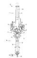
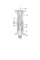
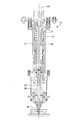
- FIG. 1 is a schematic partial cross-sectional view of the screw tightening device according to the first embodiment.
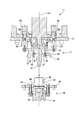
- FIG. 2A is a front view of the screw tightening device.
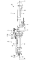
- FIG. 2B is a right side view of the screw fastening device.
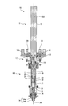
- 2C is a cross-sectional view taken along line BB shown in FIG. 2B.
- FIG. 2D is an enlarged view of the housing shown in FIG. 2C.
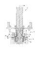
- FIG. 3A is a cross-sectional view showing the attachment / detachment mechanism.
- FIG. 3B is a cross-sectional view showing the attachment / detachment mechanism.
- FIG. 4 is a perspective view showing an alignment mechanism.
- FIG. 5 is an explanatory diagram of the operation of each part during screw gripping.
- FIG. 5 is an explanatory diagram of the operation of each part during screw gripping.
- FIG. 6 is a cross-sectional view of the bit holding portion when gripping a screw.
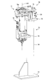
- FIG. 7 is a perspective view of the screw tightening device according to the second embodiment.
- FIG. 8A is a cross-sectional view showing the attachment / detachment mechanism.
- FIG. 8B is a cross-sectional view showing the attachment / detachment mechanism.
- FIG. 9 is a schematic diagram showing a screw tightening system.
- FIG. 10 is a functional block diagram of the screw tightening system.
- FIG. 11A is a flowchart showing timing for opening and closing the chuck.
- FIG. 11B is a flowchart showing the timing of opening and closing the chuck.
- FIG. 1 is a schematic partial cross-sectional view of the screw tightening device according to the first embodiment. Specifically, in FIG. 1, the internal structure of the bit holding unit is shown with the bit holding unit in cross section. Note that the screw tightening device described below can not only tighten the screw but also loosen the tightened screw.
- screws tightened and loosened by such a screw tightening device include bolts and the like.
- screw is used as a general term for a fastening member provided with a spiral groove such as a bolt.
- the screw fastening device 10 includes a main body part 11, an attaching / detaching part 17, a bit holding part 18, and a pressing part 27.
- the main body 11 supports a bit holding portion 18 that is engaged with a screw to be tightened and outputs a driving force around the axis AX toward the bit holding portion 18.
- the main body 11 is provided with an output shaft, which will be described later, on the distal end side in the axis AX direction.
- the attaching / detaching portion 17 is provided on the distal end side of the main body portion 11, and the end side of the bit holding portion 18 is detachably attached to the main body portion 11 so that the main body portion 11 and the bit holding portion 18 are coaxial.
- the attaching / detaching portion 17 includes an attaching / detaching mechanism for making the bit holding portion 18 attachable / detachable to / from the main body portion 11, which will be described later.
- the bit holding portion 18 includes a housing 19 and coaxially holds the bit 20 to be engaged with a screw tightened or loosened by the screw fastening device 10 on the front end side of the housing 19.
- the bit holding unit 18 further includes a socket 21 and a joint 24.
- the socket 21 is coaxially disposed inside the housing 19.
- a joint 24 that is coaxially disposed inside the housing 19 is connected to the distal end side of the socket 21.
- the bit 20 is coaxially connected to the distal end side of the joint 24.
- the housing 19, the socket 21 and the joint 24 disposed inside the housing 19, and the bit 20 connected to the joint 24 are arranged in series so as to be coaxial.
- each part (the housing 19, the socket 21, the joint 24, and the bit 20) of the main body part 11, the bit holding part 18, and the bit holding part 18 is coaxial.
- the axis AX shown in FIG. 1 is these common axes.
- the upper side (the upper end side of the main body 11) in the figure may be referred to as the end side, and the lower side (the lower end side of the bit 20) in the figure may be referred to as the leading end side.
- the socket 21 includes a rotating portion 22 and a linear motion portion 23.
- the rotating portion 22 is provided between the outer peripheral surface of the cylindrical main body in the socket 21 and the inner peripheral surface of the housing 19.
- the rotating unit 22 supports the socket 21 so as to be rotatable about the axis AX.
- the linear motion portion 23 is provided on the inner peripheral surface of the socket 21 body.
- the linear motion part 23 makes the socket 21 linearly movable in the direction of the axis AX with respect to a torque transmission shaft to be described later, and cannot rotate about the axis AX.
- the bit holding portion 18 has the socket 21 (the rotating portion 22 and the linearly moving portion 23), so that the bit 20 is rotated by the driving force around the axis AX and moves linearly following the external force in the axis AX direction. To do.
- a linear drive source such as an air cylinder for linearly driving the bit is provided on the main body side, and the drive is precisely controlled by such a linear drive source so that the bit follows the axial movement of the screw. It was the composition to do.
- a transmission mechanism for transmitting the driving force from the driving source to the bit is provided between the linear motion driving source and the bit.
- the transmission mechanism is disposed from the main body side to the bit holding part side, and the bit holding part has a large diameter.
- the transmission mechanism there is a linear drive source, and the entire apparatus is complicated and large in size.
- the pressing portion 27 that presses the bit 20 toward the distal end side is provided instead of the linear drive source. Further, as shown in FIG. 1, the pressing portion 27 is provided in the bit holding portion 18.
- the bit 20 can follow the movement of the screw in the axis AX direction. Moreover, since the pressing portion 27 presses the socket 21 that is coaxially connected to the end side of the bit 20, the pressing portion 27 can be provided on the end side of the bit holding portion 18. That is, it is not necessary to provide the pressing portion 27 on the outer peripheral side of the socket 21.
- the bit holding portion 18 can be reduced in diameter. Further, the direct drive source and the transmission mechanism are not required, and the screw fastening device 10 can be reduced in size with a simple structure.
- the pressing portion 27 is provided inside the housing 19 and the pressing portion 27 is a spring. Further, a drive source for driving the detachable portion 17 is provided on the main body portion 11 side. Such a configuration will be described later with reference to FIG. 2A and the like.
- FIG. 2A is a front view of the screw tightening device.
- FIG. 2B is a right side view of the screw fastening device.
- 2C is a cross-sectional view taken along line BB shown in FIG. 2B.
- FIG. 2D is an enlarged view of the housing shown in FIG. 2C.
- 2B is a cross section taken along the line AA shown in FIG. 2A.
- the axis AX shown in FIGS. 2A to 2D is a common axis of each part of the screw fastening device 10.
- the main body 11 side is referred to as a distal end side
- the bit 20 side is referred to as a distal end side. The same applies to the description referring to FIG.
- the screw fastening device 10 includes a main body part 11, an attaching / detaching part 17, a bit holding part 18, and a pressing part 27.
- the screw tightening device 10 is a so-called nutrunner that automatically tightens a screw (or loosens and removes the screw).
- the main body 11 includes a flat base 12 and a cylindrical casing 13 which is provided on the upper surface of the base 12 and is long in the axis AX direction.
- a first drive source 28 that drives the attaching / detaching portion 17, a block 14 that is gripped by a hand 97 (see FIG. 9) of the robot 90 described later, and the like are disposed.
- a servo motor M (see FIG. 10), a speed reducer (not shown), and the like are arranged in series in the housing 13 from the distal end side of the main body 11 to the distal end side that is the base 12 side. Is done.
- the main body 11 further includes an output shaft 15 that extends coaxially with the axis AX from the end surface on the front end side, that is, the lower surface of the base 12.
- the output shaft 15 outputs the driving force around the axis AX output from the servo motor M (see FIG. 10) to the bit holding unit 18.
- the output shaft 15 is formed with a rectangular shaft at the distal end side, and a torque transmission shaft 16 is coaxially connected to the distal end side that becomes the rectangular shaft.
- the main body 11 outputs the driving force around the axis AX from the servo motor M (see FIG. 10) to the bit holding unit 18 via the output shaft 15 (torque transmission shaft 16).
- the bit 20 held at 18 is rotationally driven. That is, the main body 11 is a drive unit that drives the bit 20.
- torque necessary for tightening or tightening the screw can be obtained by outputting the driving force from the servo motor M to the bit holding unit 18 via the reduction gear.
- the main-body part 11 is provided with the torque detector (not shown) which detects the torque of the screw to be tightened.
- the main body 11 is provided with a detachable portion 17 on the lower surface of the base 12.
- the detachable part 17 attaches the bit holding part 18 to the lower surface of the base 12 so as to be coaxial with the main body part 11.
- the attachment / detachment unit 17 includes an attachment / detachment mechanism that allows the bit holding unit 18 to be attached / detached. Details of the attachment / detachment mechanism will be described later with reference to FIGS. 3A, 3B, and 4. FIG.
- the bit holding portion 18 includes a cylindrical housing 19, and holds the bit 20 on the distal end side of the housing 19.
- the bit 20 engages with the head of the screw and rotates the screw around the axis AX (clockwise or counterclockwise).
- the bit 20 is replaceable and may be replaced depending on the type and size of the screw, or may be replaced with a new one due to wear or deterioration.
- the bit holding unit 18 further includes a socket 21 and a joint 24.
- the bit holding unit 18 holds the bit 20 via a socket 21 and a joint 24 disposed inside the housing 19.
- the socket 21 is formed in a cylindrical shape, and is disposed coaxially with the housing 19 inside the housing 19.
- the front end side of the socket 21 is connected to a joint 24 that is coaxially disposed inside the housing 19 in the same manner as the socket 21.
- the inner peripheral surface of the housing 19 is provided with a protruding portion 19a that protrudes toward the axis AX.
- the protruding portion 19 a is provided to have a slightly larger diameter than the outer peripheral surface of the socket 21.
- the socket 21 is disposed inside the housing 19 in a state where the socket 21 is regulated so as to be along the axis AX direction by the protruding portion 19a.
- the socket 21 includes a rotating portion 22 and a linear motion portion 23.
- the rotating portion 22 is provided between the outer peripheral surface of the cylindrical main body of the socket 21 and the inner peripheral surface of the housing 19 on the end side.
- the rotating part 22 is a bearing and supports the socket 21 main body so as to be rotatable around the axis AX.
- a needle bearing can be used as the rotating unit 22.
- the linear motion portion 23 is provided on the inner peripheral surface of the socket 21 body.
- the linear motion portion 23 enables the socket 21 to move linearly in the axis AX direction with respect to the torque transmission shaft 16 inserted in the axis AX direction from the terminal end side of the socket 21 and cannot rotate about the axis AX. To do.
- the torque transmission shaft 16 transmits the driving force around the axis AX output from the output shaft 15 of the main body portion 11 to the bit holding portion 18.
- a rectangular recess that can be fitted to the rectangular shaft of the output shaft 15 is provided on the upper surface (end-side end surface) of the torque transmission shaft 16.
- the outer peripheral surface of the torque transmission shaft 16 is provided with a groove extending in the axis AX direction, a so-called spline.
- the linear motion part 23 is formed in a cylindrical shape, and a spline that fits with the spline of the torque transmission shaft 16 is provided on the inner peripheral surface of the cylindrical body.
- the socket 21 moves linearly in the direction of the axis AX following the external force in the direction of the axis AX by the linearly moving portion 23 having such a spline structure.
- the socket 21 is stationary when no external force is applied.
- the socket 21 is detachable from the main body 11 side in the axis AX direction.
- the torque transmission shaft 16 has a prismatic shape and the linear motion portion 23 has an inner peripheral shape into which the torque transmission shaft 16 can be fitted.
- the joint 24 connected to the tip end side of the socket 21 rotates following the socket 21 as it rotates, and directly follows the socket 21 as it moves straight.
- the bit 20 is detachably connected to the distal end side of the joint 24.
- centering taper members 25 and 25 for extending the bit 20 in the axis AX direction are provided between the inner peripheral surface of the housing 19 and the outer peripheral surface of the socket 21. It is done.
- the taper members 25, 25 are formed in an annular shape along the inner peripheral surface of the housing 19 and the outer peripheral surface of the socket 21, and are arranged with their inclined surfaces facing each other.
- taper portions 26 and 26 for centering when the bit 20 is contracted in the axis AX direction are provided on the inner peripheral surface of the housing 19 and the outer peripheral edge of the joint 24, respectively.
- the tapered portions 26, 26 are provided with their inclined surfaces facing each other along the inner peripheral surface of the housing 19 and the outer peripheral edge of the joint 24.
- a pressing portion 27 that presses the socket 21 toward the distal end side is provided inside the housing 19.
- the pressing portion 27 is, for example, a compression coil spring, and is disposed coaxially on the end side of the socket 21.
- the socket 21 is constantly urged toward the distal end side by the spring as the pressing portion 27 via the linear motion portion 23. That is, the bit 20 integrally connected to the socket 21 and the joint 24 in the axis AX direction is pressed toward the distal end side by the urging force of the pressing portion 27 via the socket 21 and the joint 24.
- FIG. 3A is a cross-sectional view showing an attaching / detaching mechanism of the attaching / detaching portion (before attaching the bit holding portion).
- FIG. 3B is a cross-sectional view showing the attaching / detaching mechanism of the attaching / detaching portion (after the bit holding portion is attached).
- the attachment / detachment unit 17 includes a pair of air cylinders 28, 28 as a first drive source.
- the pair of air cylinders 28 and 28 are disposed on the upper surface of the base 12 on the main body part 11 side with a phase difference of 180 degrees on a concentric circle of the axis AX.
- Each of the telescopic rods 28a, 28a of the pair of air cylinders 28, 28 penetrates the base 12 and the tip side is disposed on the bit holding unit 18 side.
- the extensible rods 28a and 28a are connected to the floating joints 29 and 29 on the bit holding portion 18 side at the distal end side.
- Floating joints 29 and 29 are connected to a flange portion 31 provided on the outer peripheral surface of a short cylindrical circular receiving portion 30.
- the circular receiving portion 30 is provided so as to be extendable and contractible in the axis AX direction, and expands and contracts in the axis AX direction following the extension and contraction of the extension rods 28a and 28a.
- the circular receiving part 30 is provided with a circular concave part 32 on the end face side end face.
- the inner peripheral surface of the circular recess 32 is a tapered surface 33 provided to be inclined so as to increase the diameter.
- the circular receiving portion 30 is provided with a communication hole 34 that communicates from the main body portion 11 side to the bit holding portion 18 side.
- the cylindrical portion 35 is fitted into the communication hole 34.
- the cylindrical portion 35 is inserted with the output shaft 15 of the main body 11 when the bit holding portion 18 is attached.
- a tapered surface 36 is provided on the inner peripheral edge on the distal end side of the cylindrical portion 35 so as to increase the diameter.
- a through hole 37 penetrating in the thickness direction is provided on the inner peripheral surface of the cylindrical portion 35.
- a steel ball 38 is disposed in the through hole 37.
- the opening diameter on the inner peripheral surface side of the through hole 37 is formed smaller than the diameter of the steel ball 38.
- a flange 39 is provided on the end face of the bit holding unit 18.
- a circular convex portion 40 that can be fitted into the circular concave portion 32 on the main body portion 11 side is provided on the end side end face of the flange portion 39.
- a cylindrical part 41 that can be fitted into the cylindrical part 35 on the main body part 11 side is provided on the end face of the circular convex part 40.
- a V-shaped groove 42 is provided on the outer peripheral surface of the cylindrical portion 41 on the end side.
- a tapered surface 43 is provided on the side peripheral surface of the circular convex portion 40 so as to be inclined toward the distal end surface.
- the cylinder part 41 on the bit holding part 18 side is fitted into the cylindrical part 35 on the main body part 11 side.
- the output shaft 15 is inserted through the tube portion 41.
- the output shaft 15 enters the inside of the housing 19 through the inner peripheral surface of the cylindrical portion 41, and the tip end side is connected to the terminal end side of the torque transmission shaft 16.
- the steel ball 38 disposed in the through hole 37 is pushed out to the inner peripheral surface side of the cylindrical portion 35 by a predetermined dimension by the inner peripheral surface of the communication hole 34.
- the steel ball 38 is restricted from protruding more than a predetermined dimension.
- the steel ball 38 protruding by a predetermined dimension is fitted into a V-shaped groove 42 provided in the cylinder part 41 on the bit holding part 18 side.
- the steel ball 38 is fitted into the V-shaped groove 42, the tapered surface 36 of the body portion 11 side tubular portion 35 and the tapered surface 43 of the tubular portion 41 on the bit holding portion 18 side come into contact with each other.
- the bit holding is performed by the force with which the steel ball 38 presses the V-shaped groove 42 and the force with which the tapered surface 36 of the cylindrical portion 35 on the main body 11 side presses the tapered surface 43 of the cylindrical portion 41 on the bit holding portion 18 side.
- the part 18 is locked to the main body part 11.
- the bit holding part 18 is detachably attached to the main body part 11 by such a so-called coupler structure attaching / detaching mechanism. Further, it can be easily attached and detached by a simple operation.
- FIG. 4 is a perspective view showing a positioning mechanism of the attaching / detaching portion.
- the attaching / detaching portion 17 includes a positioning mechanism for preventing the main body portion 11 and the bit holding portion 18 from rotating around the axis AX when or after the bit holding portion 18 is attached.
- the detachable portion 17 includes a positioning pin 44 and a bush 47 as a positioning mechanism.
- the positioning pin 44 includes a base portion 45 that protrudes from the lower surface of the base 12 of the main body portion 11 toward the distal end side, and a pin portion 46 that protrudes further from the distal end side end surface of the base portion 45 toward the distal end side.
- the bush 47 is attached to a through hole provided in the flange portion 39 of the bit holding portion 18 and is provided so that the pin portion 46 of the positioning pin 44 can be inserted.
- the position where the bush 47 is provided is a position corresponding to the position of the positioning pin 44 after the bit holder 18 is mounted.
- the attachment / detachment unit 17 includes a phase matching mechanism using a dog or a sensor, for example.
- the screw tightening device 10 further includes a second drive source 50, an arm 52, and a chuck 54 as a screw gripping mechanism.
- the air cylinder 50 as the second drive source includes an extendable rod 50a that expands and contracts from the cylinder in the axis AX direction.
- a spring portion 51 is connected to the distal end side of the telescopic rod 50a.
- the spring portion 51 includes a spring 51a and a rod 51b inside the cylinder.
- a compression coil spring can be used as the spring 51a.
- the air cylinder 50 and the spring portion 51 are arranged coaxially in parallel with the axis AX direction.
- the rod 51 b biased by the spring 51 a is connected to the arm 52 on the distal end side.
- the arm 52 is formed in a rectangular plate shape.
- the arm 52 is provided with a bent portion so as to be close to the housing 19 side of the bit holding portion 18.
- a linear guide 53 is provided between the arm 52 and the housing 19 to guide the linear movement of the arm 52 in the direction parallel to the axis AX direction.
- the arm 52 is connected to the link portion of the chuck 54 on the distal end side.
- the chuck 54 includes a pair of arm portions 54a and 54a and claw portions 54b and 54b.
- Each of the arm portions 54a and 54a includes a plurality (three) of shafts.
- a link part is formed by the arm part 54a, the claw part 54b, and the shaft.
- the chuck 54 is opened and closed via the arm 52 by the expansion and contraction of the expansion rod 50a.
- the spring portion 51 is always biased so as to open the chuck 54 by elastic deformation of the spring 51a. As a result, an appropriate grip force can be obtained when the chuck 54 grips the screw.
- the chuck 54 is provided to be rotatable around the axis AX. 2B, the chuck 54 opens and closes in a direction perpendicular to the thickness direction of the arm 52. In FIG. 2B, for example, the chuck 54 can be opened and closed in a direction parallel to the thickness direction of the arm 52. .
- FIG. 5 is an explanatory diagram of the operation of each part during screw gripping.
- the upper half of the drawing shows a state where the bit is engaged with the screw, and the lower half shows a state where the chuck is closed and the screw is gripped therefrom.
- the bit 20 engaged with the screw 60 resists the pressure of the spring 27 (see FIG. 2C etc.) as the pressing portion, and the end of the bit holding portion 18. It closes in the state which moved only the length of the screw 60 to the side. Further, the closed chuck 54 is opened before the bit 20 starts rotating to tighten the screw 60.
- the chuck 54 when the loosening of the screw 60 is completed, the bit 20 resists the pressure of the spring 27 (see FIG. 2C and the like) as the pressing portion. It closes in a state where it has moved to the end side by the length of the screw 60 and in a state where the rotation of the bit 20 has stopped.
- timing for opening and closing the chuck 54 may be configured to be controlled by a control device 300 (see FIG. 9 and FIG. 10) described later.
- the screw tightening device 10 itself may include a controller alone, and may be configured to be controlled by such a controller.
- the screw tightening device 10 is provided with a mechanical opening / closing operation unit. For example, there are various methods for realizing timing control such as operating the operation unit manually.
- FIG. 6 is a cross-sectional view of the bit holding portion when gripping a screw.
- the socket 21 moves linearly while being guided by the linear movement portion 23 of the spline structure. Due to the movement of the socket 21 (the linear motion portion 23) toward the end side, the spring 27 as the pressing portion is compressed, and the elastically deformed spring 27 presses the bit 20 on the distal end side through the socket 21 and the joint 24. As a result, the bit 20 is always pressed against the screw 60.
- the screw 60 to be tightened or loosened by providing the bit holding portion 18 with the pressing portion 27 that constantly presses the bit 20 toward the distal end side of the bit holding portion 18.
- the bit 20 can follow the movement in the axis AX direction. This eliminates the need for a drive source and a transmission mechanism that have been required to follow the movement of the screw 60 in the axis AX direction, and enables the bit holding portion 18 to have a small diameter. Further, the screw fastening device 10 as a whole is simple in structure and small in size.
- Such a pressing portion 27 is provided inside the bit holding portion 18 (housing 19), whereby the bit holding portion 18 can be further reduced in diameter.
- a simple member such as a spring for the pressing portion 27, the screw fastening device 10 can be configured simply, compactly, and inexpensively.
- the screw tightening device 10 since the first drive source (air cylinder) 28 for driving the attaching / detaching portion 17 is provided on the main body portion 11 side, the bit holding portion 18 is further reduced in diameter, and the screw tightening device 10 is further increased. Simple structure and small size.
- FIG. 7 is a perspective view of the screw tightening device according to the second embodiment.
- the second embodiment described below differs from the first embodiment described above in that the first drive source is provided on the gantry side.
- the same or similar parts as those in the first embodiment appearing in the description of the second embodiment are denoted by the same reference numerals, and the description thereof is omitted.
- the screw fastening device 70 includes a gantry 72 that supports the device main body 71 of the screw fastening device 70.
- the screw fastening apparatus main body 71 is the structure equivalent to the screw fastening apparatus 10 (refer FIG. 2A etc.) based on 1st Embodiment except the point demonstrated below.
- the main body 11 see FIG. 8A and the like) to which the bit holding unit 18 is attached is omitted.
- the gantry 72 includes a base portion 73 and a column portion 74 erected from the base portion 73 in parallel with the axis AX direction.
- a pair of air cylinders 28, 28 as a first drive source are provided on the mount 72 side.
- a rectangular plate-shaped mounting portion 75 is provided on the upper portion of the support column 74, and the pair of air cylinders 28 and 28 are mounted on the mounting portion 75.
- the pair of air cylinders 28 and 28 extend and contract the respective expansion / contraction rods 28a and 28a toward the distal end in parallel with the axis AX direction.
- a horizontal plate 76 is coupled to the telescopic rods 28a and 28a.
- the telescopic rods 28a, 28a move (directly move) the horizontal plate 76 in a direction parallel to the axis AX direction.
- the horizontal plate 76 is formed in a rectangular plate shape, and one end side is connected to the telescopic rods 28a and 28a so as to be arranged on the pedestal 72 side, and the other end side is arranged on the screw fastening device main body 71 side.
- a cutout 76a is provided on the other end side of the horizontal plate 76, and an end side end portion of the bit holding portion 18 is disposed inside the cutout 76a.
- a substantially U-shaped plate 79 that extends toward the bit holding unit 18 and has a substantially rectangular notch on the bit holding unit 18 side is provided at a midway position of the support column 74.
- a flange having a two-sided width process is provided at the lower portion of the outer peripheral surface of the bit holding portion 18 so as to fit into the notch. For this reason, the bit holding part 18 is inserted into the notch with a constant angle around the axis.
- the bit holding portion 18 is attached to the pedestal 72 in an aligned state by being fitted into the notch of the plate 79.
- FIG. 8A and FIG. 8B are cross-sectional views showing the attaching / detaching mechanism of the attaching / detaching portion.
- the attachment / detachment portion 77 has a spring (for example, a compression coil spring) 78 in the space between the inner peripheral surface of the circular receiving portion 30 and the outer peripheral surface of the cylindrical portion 35 on the main body portion 11 side. Arranged.
- the circular receiving portion 30 moves linearly in the direction of the axis AX and is urged toward the distal end side by the spring 78.
- the main body portion 11 is arranged coaxially with the bit holding portion 18 held by the mount 72. . Thereafter, when the main body portion 11 is moved to the tip side, that is, the bit holding portion 18 side, the cylindrical portion 41 on the bit holding portion 18 side is inserted into the cylindrical portion 35 on the main body portion 11 side.
- the horizontal plate 76 is moved to the distal side by the telescopic rods 28a, 28a of the pair of air cylinders 28, 28 on the gantry 72 side. And moved (raised). Further, as the horizontal plate 76 is raised, the circular receiving portion 30 on the main body portion 11 side is pushed up against the biasing force of the spring 78 toward the end side.
- the bit holding part 18 is detachably attached to the main body part 11 by such a so-called coupler structure attaching / detaching mechanism. Further, it can be easily attached and detached by a simple operation.
- the bit holding unit 18 is provided with the pressing portion 27 that constantly presses the bit 20 toward the distal end side of the bit holding portion 18 as in the first embodiment described above. Accordingly, the bit 20 can be made to follow the movement of the screw to be tightened in the axis AX direction. Thereby, the bit holding portion 18 can be reduced in diameter, and the screw tightening device main body 71 can be simplified in structure and reduced in size.
- the bit holding portion 18 can be further reduced in diameter by providing the pressing portion 27 inside the bit holding portion 18 (housing 19). Further, by using a simple member such as a spring for the pressing portion 27, the screw tightening device main body 71 can be configured simply, compactly, and inexpensively.
- the screw tightening device 70 since the first drive source (the pair of air cylinders 28, 28) for driving the attaching / detaching portion 77 is provided on the gantry 72 side, the bit holding portion 18 has a smaller diameter, and the screw tightening device main body. 71 is further simple in structure and small in size.
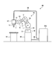
- FIG. 9 is a schematic diagram showing a screw tightening system.
- the screw tightening device will be described as the screw tightening device 10 according to the first embodiment (see FIG. 2A and the like).
- the screw tightening system 80 includes a screw tightening device 10, a robot 90, and a control device 300.
- the screw tightening system 80 also includes a workbench 62 that tightens or loosens the screws.
- screws 60 are installed on the screw table 61 (see FIG. 5). The description of the screw tightening device 10 is omitted.
- the robot 90 is, for example, a single-armed multi-joint robot.
- the robot 90 includes a first arm unit 91, a second arm unit 92, a third arm unit 93, a fourth arm unit 94, a fifth arm unit 95, and a base unit 96.
- the robot 90 may be a double arm type.
- the first arm portion 91 is supported at the base end portion by the second arm portion 92.
- the second arm portion 92 is supported at the base end portion by the third arm portion 93 and supports the first arm portion 91 at the distal end portion.
- the third arm portion 93 is supported at the base end portion by the fourth arm portion 94 and supports the second arm portion 92 at the tip end portion.
- the fourth arm portion 94 is supported at the base end portion by the fifth arm portion 95 and supports the third arm portion 93 at the distal end portion.
- the fifth arm portion 95 is supported at the base end portion by the base portion 96 fixed to the floor surface or the like, and supports the fourth arm portion 94 at the front end portion.
- an actuator such as a servo motor is mounted on each joint portion (not shown) that is a connecting portion of the first arm portion 91 to the fifth arm portion 95.
- the robot 90 can perform a multi-axis operation by driving an actuator.
- the joint actuator that connects the first arm 91 and the second arm 92 rotates the first arm 91 about the B axis.
- the joint actuator that connects the second arm part 92 and the third arm part 93 rotates the second arm part 92 about the U axis.
- the joint actuator that connects the third arm part 93 and the fourth arm part 94 rotates the third arm part 93 around the L axis. Further, the actuator at the joint that connects the fourth arm portion 94 and the fifth arm portion 95 rotates the fourth arm portion 94 around the S axis.
- the robot 90 includes individual actuators that rotate the first arm 91 around the T axis, the second arm 92 around the R axis, and the third arm 93 around the E axis.
- the robot 90 has seven axes. Then, the robot 90 can perform various multi-axis operations combining seven axes based on an operation instruction from a control unit 301 (see FIG. 10) of the control device 300 described later.
- the distal end portion of the first arm portion 91 is a distal end movable portion of the robot 90, and a hand 97 is attached to the distal end movable portion.
- the hand 97 grips the block 14 (see FIG. 2A and the like) of the screw fastening device 10 at the most distal portion of the robot 90.
- the control device 300 is a so-called robot controller, and drives and controls the actuators of the joint portions including the arm portions 91 to 95 and the hand 97 of the robot 90.
- the control device 300 and the robot 90 are connected by a cable 98 or the like.
- control device 300 drives and controls the first drive source 28 (see FIG. 3A and the like) and the second drive source 50 (see FIG. 2B and the like) of the screw tightening device 10.
- the control device 300 is connected to the first drive source 28 and the second drive source 50 by a cable 99 or the like.
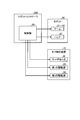
- FIG. 10 is a functional block diagram of the screw tightening system. Note that FIG. 10 shows components necessary for screw tightening, attachment / detachment, and driving of the chuck.
- a robot controller 300 as a control device includes a control unit 301.
- the control unit 301 generates a signal for operating the robot 90 based on the teaching information and outputs the signal to the robot 90.
- control unit 301 generates and outputs a signal for operating the servo motor M toward the screw tightening device 10. Further, the control unit 301 outputs signals for operating the first drive source 28 and the second drive source 50 included in the screw tightening device 10 to the drive sources 28 and 50.
- the operation signal output from the control unit 301 is generated as a pulse signal to a servo motor (not shown) mounted on each of the joints of the arms 91 to 95 and the hand 97 included in the robot 90.
- the “arm” refers to the first arm portion 91 to the fifth arm portion 95 described above.
- the operation signal output from the control unit 301 is the screw tightening device 10, the servo motor M provided in the screw tightening device 10, the first drive source 28 driven by the attaching / detaching mechanism, and the first driven by the screw gripping mechanism. 2 as a signal to the driving source 50.
- a programmable controller and a screw tightening device controller for strict control of torque by screw tightening may be disposed between the control unit 301 and the servo motor M of the screw tightening device 10.
- the screw tightening device 10 includes a torque detector (not shown). Torque detected by the torque detector is output to the control unit 301. When the detected torque reaches a predetermined torque indicating completion of screw tightening, a signal is output to the control unit 301. And the control part 301 outputs the signal which stops operation
- a torque detector not shown.
- the robot places the screw tightening device gripped by the hand coaxially with the screw.
- the screw is located at a place different from the work position (screw hole) and the work is started from there.
- the robot moves the screw tightening device in the axial direction to the screw side and engages the bit at the tip with the screw. Thereafter, the chuck closes and grips the screw head. Then, the robot moves the screw tightening device to the screw hole and installs the screw held by the chuck in the screw hole.
- the chuck When the screw is installed in the screw hole, the chuck is opened to release the screw. When the gripping of the screw by the chuck is released, the bit starts to rotate.
- the bit is set to rotate clockwise, but when the screw to be tightened is a reverse screw or the like, the bit is set to rotate counterclockwise.
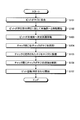
- FIG. 11A is a flowchart showing the timing of opening and closing the chuck in the screw tightening operation.
- the control for opening and closing the chuck at a predetermined timing is performed by the control unit 301 (see FIG. 10) of the control device (robot controller) 300 as described above.
- step S101 when the bit is engaged with the screw (step S101) and the screw fastening device is further moved to the screw side as it is, the bit moves toward the end side of the bit holding portion against the pressing of the pressing portion.
- the movement is started (step S102).
- step S103 When the bit moves to the end side by a predetermined distance, that is, the length of the screw (step S103), the chuck is closed (step S104). As a result, the chuck is in a state of gripping the screw.
- step S105 when the screw held by the chuck is installed in the screw hole (step S105), the chuck opens (step S106), and the chuck releases the screw. When the grip of the screw is released, the bit starts to rotate clockwise (step S107).
- the robot places the screw tightening device held by the hand coaxially with the tightened screw. Then, the robot moves the screw tightening device to the screw side and engages the bit at the tip with the tightened screw.
- the bit When the bit is engaged with the screw, the bit starts to rotate.
- the bit is set to rotate counterclockwise, but when the screw to be loosened is a reverse screw or the like, the bit is set to rotate clockwise.
- control unit 301 determines whether or not the rotation time of the bit has passed a predetermined time. This time is preset according to the length of the screw to be loosened. When it is determined that the predetermined time has elapsed, the rotation of the bit is stopped by an instruction from the control unit 301. If it is determined that the predetermined time has not elapsed, the bit rotation continues until the predetermined time elapses.
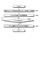
- FIG. 11B is a flowchart showing the timing of opening and closing the chuck in the screw loosening operation.
- Step S201 the bit that engages and rotates with the screw to loosen the screw is pushed while the screw is retracted in the axial direction, and the end side of the bit holding portion resists the pressing of the pressing portion.
- step S202 it is determined by the control unit 301 (see FIG. 10) whether the bit has stopped rotating (step S203).
- step S203 If it is determined that the bit has stopped rotating (step S203, Yes), the chuck is closed (step S204). As a result, the chuck is in a state of gripping the screw. If it is determined in the process of step S203 that the bit has not stopped rotating (No in step S203), the bit continues to rotate, and the chuck remains open during that time.
- the work range is widened by performing the screw tightening operation and the screw loosening operation by the robot 90.
- each operation of engaging the bit 20 with the screw 60, arranging the screw 60 in the screw hole, and moving the screw 60 from the screw hole can be automatically performed by the cooperation of the screw tightening device 10 and the robot 90.
- the screw 60 can be prevented from popping out by the pressing of the bit 20 by closing the chuck 54 in a state where the bit 20 has moved to the end side of the bit holding portion 18.
- the chuck 54 that is closed in a state where the screw 60 is gripped is opened before the bit 20 starts to rotate, so that the bit 20 when the screw 60 is installed in the screw hole.
- the screw 60 can be prevented from popping out by pressing.
- the screw 60 is popped out by closing the chuck 54 with the bit 20 moved to the end side of the bit holding portion 18 and with the bit 20 stopped rotating. In addition, the danger of gripping the rotating screw 60 can be avoided.
Landscapes
- Engineering & Computer Science (AREA)
- Mechanical Engineering (AREA)
- Details Of Spanners, Wrenches, And Screw Drivers And Accessories (AREA)
Abstract
実施形態の一態様に係るネジ締め装置は、ビット保持部と、押圧部と、本体部と、着脱部とを備える。ビット保持部は、軸まわりの駆動力によって回転する回転部および軸方向の外力に倣って直動する直動部を有しており、ビットを直動部よりも先端側において軸と同軸で保持する。押圧部は、ビット保持部に設けられ、直動部を先端側へ押圧する。本体部は、ビット保持部を支持する。着脱部は、本体部に設けられ、ビット保持部の末端側を本体部に対して着脱自在とする。
Description
開示の実施形態は、ネジ締め装置およびネジ締めシステムに関する。
従来、ネジを自動で締め付けるネジ締め装置には、ビット保持部を着脱自在として、ネジの種類やサイズに応じてビット保持部を交換可能とするネジ締め装置がある。
かかるネジ締め装置は、ネジに係合させるビットを回転駆動してネジを締めるかまたは緩めるが、締緩させるネジの軸方向の移動に追従させるようにビットを直線駆動する駆動源(エアシリンダ等)を備えることが一般的である。
また、かかるネジ締め装置では、直線駆動のための駆動源とビットを保持するビット保持部との間に、駆動源からビットへと直線駆動力を伝えるための伝達機構が設けられる(たとえば、特許文献1参照)。
しかしながら、上述したような従来のネジ締め装置は、直線駆動の駆動源を備えるうえビット保持部へと通じる直線駆動力の伝達機構があることから、ビット保持部が大径となり、装置全体としても構造複雑で大型であった。
また、かかるネジ締め装置を狭い場所等で使用すると周囲との干渉の問題が起こることがある。そのため、従来のネジ締め装置は、その使用可能な場所が限られていた。
実施形態の一態様は、上記に鑑みてなされたものであって、ビット保持部を小径にすることができるネジ締め装置およびネジ締めシステムを提供することを目的とする。
実施形態の一態様に係るネジ締め装置は、ビット保持部と、押圧部と、本体部と、着脱部とを備える。前記ビット保持部は、軸まわりの駆動力によって回転する回転部および前記軸方向の外力に倣って直動する直動部を有しており、ビットを前記直動部よりも先端側において前記軸と同軸で保持する。前記押圧部は、前記ビット保持部に設けられ、前記直動部を前記先端側へ押圧する。前記本体部は、前記ビット保持部を支持する。前記着脱部は、前記本体部に設けられ、前記ビット保持部の末端側を前記本体部に対して着脱自在とする。
実施形態の一態様によれば、ビット保持部を小径にすることができる。
以下、添付図面を参照して、本願の開示するネジ締め装置およびネジ締めシステムの実施形態を詳細に説明する。なお、以下に示す実施形態によりこの発明が限定されるものではない。
(第1の実施形態)
図1は、第1の実施形態に係るネジ締め装置の模式的な一部断面図である。具体的には、図1では、ビット保持部を断面にして、ビット保持部の内部構成を示している。なお、これから説明するネジ締め装置は、ネジを締めるだけでなく、締め付けられたネジを緩めることもできる。
図1は、第1の実施形態に係るネジ締め装置の模式的な一部断面図である。具体的には、図1では、ビット保持部を断面にして、ビット保持部の内部構成を示している。なお、これから説明するネジ締め装置は、ネジを締めるだけでなく、締め付けられたネジを緩めることもできる。
また、このようなネジ締め装置によって締緩されるネジにはボルト等も含む。ここでは「ネジ」という呼称をボルト等のようならせん状の溝が設けられた締結部材の総称として用いる。
図1に示すように、ネジ締め装置10は、本体部11と、着脱部17と、ビット保持部18と、押圧部27とを備える。本体部11は、締緩されるネジに係合させるビット保持部18を支持し、ビット保持部18に向けて軸AXまわりの駆動力を出力する。なお、本体部11には、軸AX方向の先端側に後述する出力軸が設けられる。
また、着脱部17は、本体部11の先端側に設けられ、本体部11とビット保持部18とが同軸となるように、本体部11にビット保持部18の末端側を着脱自在に取り付ける。なお、着脱部17は、本体部11に対してビット保持部18を着脱自在とするための着脱機構を備えるが、この点については後述する。
また、ビット保持部18は、ハウジング19を備え、ハウジング19の先端側に、ネジ締め装置10によって締緩されるネジに係合させるビット20を同軸で保持する。
具体的には、ビット保持部18は、ソケット21と、ジョイント24とをさらに備える。ソケット21は、ハウジング19の内部に同軸で配設される。ソケット21の先端側には、ハウジング19の内部に同軸で配設されるジョイント24が連結される。ジョイント24の先端側にはビット20が同軸で連結される。
ビット保持部18では、ハウジング19と、ハウジング19の内部に配設されるソケット21およびジョイント24と、ジョイント24に連結されるビット20とが同軸となるように直列に配置される。
すなわち、本体部11、ビット保持部18およびビット保持部18の各部(ハウジング19、ソケット21、ジョイント24およびビット20)は同軸となる。図1に示す軸AXは、共通するこれらの軸である。
なお、以下の説明では、図中上側(本体部11の上端側)を末端側と称し、図中下側(ビット20の下端側)を先端側と称する場合がある。
以下では、ソケット21についてさらに詳細に説明する。図1に示すように、ソケット21は、回転部22と直動部23とを備える。回転部22は、ソケット21における筒状本体の外周面とハウジング19の内周面との間に設けられる。回転部22は、ソケット21を軸AXまわりに回転可能に支持する。
直動部23は、ソケット21本体の内周面に設けられる。直動部23は、ソケット21を、後述するトルク伝達軸に対して軸AX方向に直動可能とし、かつ、軸AXまわりに回転不可能とする。
ビット保持部18は、ソケット21(回転部22および直動部23)を有することで、軸AXまわりの駆動力によって回転するとともに軸AX方向の外力に倣って直動するようにビット20を保持する。
ところで、ネジ締め装置10では、ネジを締めるかまたは緩める場合、締緩されるネジの軸AX方向の移動にビット20を追従させてビット20とネジとの係合状態を維持する必要がある。
従来は、本体部側にビットを直線駆動するためのエアシリンダ等の直動駆動源を備え、このような直動駆動源によってビットをネジの軸方向の移動に追従させるように精密に駆動制御する構成であった。
また、従来のネジ締め装置では、直動駆動源とビットとの間に、駆動源からビットへと駆動力を伝達するための伝達機構を設けていた。
そのため、従来のネジ締め装置は、本体部側からビット保持部側にかけて伝達機構が配設されることになり、ビット保持部が大径であった。また、伝達機構の他に直動駆動源があり、装置全体としても構造複雑で大型であった。
そこで、第1の実施形態に係るネジ締め装置10では、ビット20を先端側へ押圧する押圧部27を直動駆動源に代えて設けることとした。また、図1に示すように、押圧部27をビット保持部18に設けることとした。
直動駆動源に代えてビット保持部18に押圧部27を設けることにより、ビット20をネジの軸AX方向の移動に追従させることができる。しかも、押圧部27は、ビット20の末端側に同軸で連結されるソケット21を押圧することから、ビット保持部18の末端側に設けることができる。すなわち、押圧部27をソケット21の外周側に設ける必要がない。
この結果、ビット保持部18を小径にすることができる。さらに、直動駆動源および伝達機構が不要となり、ネジ締め装置10を簡素な構造で小型にすることができる。
なお、第1の実施形態に係るネジ締め装置10では、押圧部27をハウジング19の内部に設けるとともに、押圧部27をばねとした。さらに、着脱部17を駆動するための駆動源を本体部11側に設けた。このような構成については、図2A等を用いて後述する。
以下では、図2A~図2Dを参照して第1の実施形態に係るネジ締め装置についてさらに詳しく説明する。図2Aは、ネジ締め装置の正面図である。図2Bは、ネジ締め装置の右側面図である。図2Cは、図2Bに示すB-B線断面図である。図2Dは、図2Cに示すハウジングの拡大図である。なお、図2Bに示す斜線部分は、図2Aに示すA-A線断面である。
また、図2A~図2Dに示す軸AXは、ネジ締め装置10各部の共通する軸である。なお、図1の説明と同様に、本体部11側を末端側と称し、ビット20側を先端側と称する。これらは図3以降を参照する説明においても同様である。
図2Aおよび図2Bに示すように、ネジ締め装置10は、本体部11と、着脱部17と、ビット保持部18と、押圧部27とを備える。なお、ネジ締め装置10は、自動でネジを締め付ける(またはネジを緩めて取り外す)、いわゆるナットランナである。
図2Aおよび図2Bに示すように、本体部11は、平板状のベース12と、ベース12上面に設けられ、軸AX方向に長い筒状の筐体13とを備える。ベース12上面には、筐体13の他、着脱部17を駆動する第1の駆動源28や後述するロボット90のハンド97(図9参照)に把持されるブロック14等が配設される。
また、筐体13の内部には、本体部11の末端側からベース12側となる先端側にかけて、サーボモータM(図10参照)や減速機(図示せず)等が直列に並んで配設される。
図2Cに示すように、本体部11は、先端側端面、すなわち、ベース12下面から軸AXと同軸で延出する出力軸15をさらに備える。出力軸15は、サーボモータM(図10参照)から出力される軸AXまわりの駆動力をビット保持部18へと出力する。出力軸15は、先端側が矩形軸に形成され、矩形軸となる先端側にトルク伝達軸16が同軸で連結される。
このように、本体部11は、出力軸15(トルク伝達軸16)を介してサーボモータM(図10参照)からの軸AXまわりの駆動力をビット保持部18へと出力し、ビット保持部18に保持されるビット20を回転駆動する。すなわち、本体部11は、ビット20を駆動する駆動部となる。
本体部11では、減速機を介してサーボモータMから駆動力をビット保持部18へと出力することで、ネジの締緩に必要なトルクが得られる。また、本体部11は、締緩されるネジのトルクを検出するトルク検出器(図示せず)を備える。
図2Aおよび図2Bに示すように、本体部11には、ベース12下面に着脱部17が設けられる。着脱部17は、ベース12下面に、本体部11に対して同軸となるようにビット保持部18を取り付ける。着脱部17は、ビット保持部18を着脱自在とする着脱機構を備える。着脱機構の詳細については、図3A、図3Bおよび図4を用いて後述する。
図2Aおよび図2Bに示すように、ビット保持部18は、円筒状のハウジング19を備え、このハウジング19の先端側にビット20を保持する。
ビット20は、ネジの頭部に係合して、ネジを軸AXまわり(時計まわりまたは反時計まわり)に回転させる。ビット20は交換可能であり、ネジの種類やサイズに応じて交換することもあれば、磨耗や劣化で新品と交換することもある。
図2Cおよび図2Dに示すように、ビット保持部18は、ソケット21と、ジョイント24とをさらに備える。ビット保持部18は、ハウジング19の内部に配設されるソケット21およびジョイント24を介してビット20を保持する。
図2Cに示すように、ソケット21は、筒状に形成され、ハウジング19の内部にこのハウジング19と同軸で配設される。ソケット21の先端側は、このソケット21と同様にハウジング19の内部に同軸で配設されるジョイント24に連結される。
図2Dに示すように、ハウジング19の内周面には、軸AXに向けて突出する突出部19aが設けられる。突出部19aは、ソケット21の外周面よりも僅かに大径となるように設けられる。ソケット21は、突出部19aによって軸AX方向に沿うように規制された状態でハウジング19の内部に配設される。
ソケット21は、回転部22と直動部23とを備える。回転部22は、ソケット21の筒状本体の外周面と末端側におけるハウジング19の内周面との間に設けられる。回転部22は、軸受であり、ソケット21本体を軸AXまわりに回転可能に支持する。なお、回転部22としては、たとえば、ニードルベアリングを用いることができる。
直動部23は、ソケット21本体の内周面に設けられる。この直動部23は、ソケット21を、ソケット21の末端側から軸AX方向に挿入されるトルク伝達軸16に対して軸AX方向に直動可能とし、かつ、軸AXまわりに回転不可能とする。
トルク伝達軸16は、本体部11の出力軸15から出力される軸AXまわりの駆動力をビット保持部18へと伝達する。トルク伝達軸16の上面(末端側端面)には、出力軸15の矩形軸と嵌合可能な矩形凹部が設けられる。
トルク伝達軸16の外周面には、軸AX方向に伸びる溝、いわゆるスプラインが設けられる。一方、直動部23は、筒状に形成され、筒体の内周面にトルク伝達軸16のスプラインと嵌合するスプラインが設けられる。
このようなスプライン構造の直動部23によって、ソケット21は、軸AX方向の外力に倣ってこの軸AX方向に直動する。ソケット21は、外力が付与されない状態では静止する。また、ソケット21は、軸AX方向については、本体部11側から動力的に切り離される。
なお、スプライン構造以外に直動機能を有する構成としては、たとえば、トルク伝達軸16を角柱形状とし、直動部23をトルク伝達軸16が嵌入可能な内周形状とするような構成がある。
図2Cに示すように、ソケット21の先端側に連結されるジョイント24は、ソケット21が回転するとこれに追従して回転し、ソケット21が直動するとこれに追従して直動する。ジョイント24の先端側にはビット20が着脱可能に連結される。
図2Cおよび図2Dに示すように、ハウジング19の内周面とソケット21の外周面との間には、それぞれにビット20を軸AX方向に伸ばす場合の芯出しのテーパ部材25,25が設けられる。テーパ部材25,25は、ハウジング19の内周面およびソケット21の外周面に沿って環状に形成され、互いの傾斜面を対向させて配置される。
図2Cに示すように、ハウジング19の内周面およびジョイント24の末端側外周縁のそれぞれには、ビット20を軸AX方向に縮める場合の芯出しのテーパ部26,26が設けられる。テーパ部26,26は、ハウジング19の内周面およびジョイント24の外周縁に沿って互いの傾斜面を対向させて設けられる。
図2Cに示すように、ハウジング19の内部には、ソケット21を先端側へと押圧する押圧部27が設けられる。押圧部27は、たとえば、圧縮コイルばねであり、ソケット21の末端側に同軸で配設される。
ソケット21は、押圧部27であるばねによって、直動部23を介して先端側へと常時付勢される。すなわち、ソケット21およびジョイント24と軸AX方向に一体的に連結されるビット20は、ソケット21とジョイント24とを介して押圧部27の付勢力によって先端側へと押圧される。
ここから、図3Aおよび図3Bを参照して着脱部の着脱機構について説明する。図3Aは、着脱部の着脱機構(ビット保持部の装着前)を示す断面図である。図3Bは、着脱部の着脱機構(ビット保持部の装着後)を示す断面図である。
図3Aに示すように、着脱部17は、第1の駆動源としての一対のエアシリンダ28,28を備える。一対のエアシリンダ28,28は、本体部11側となるベース12上面において軸AXの同心円上に180度の位相差で配設される。
一対のエアシリンダ28,28のそれぞれの伸縮ロッド28a,28aは、ベース12を貫通して先端側がビット保持部18側に配置される。伸縮ロッド28a,28aは、先端側がビット保持部18側でフローティングジョイント29,29に連結される。
フローティングジョイント29,29は、短筒状の円形受部30の外周面に設けられたフランジ部31に連結される。円形受部30は、軸AX方向に伸縮可能に設けられ、伸縮ロッド28a,28aの伸縮に追従して軸AX方向に伸縮する。
円形受部30には、先端側端面に円形凹部32が設けられる。円形凹部32の内周面は、拡径するように傾斜して設けられたテーパ面33である。また、円形受部30には、本体部11側からビット保持部18側まで連通する連通穴34が設けられる。
連通穴34には、筒部35が嵌入される。筒部35には、ビット保持部18の装着状態において本体部11の出力軸15が挿通される。筒部35の先端側内周縁には、拡径するようにテーパ面36が設けられる。
筒部35の内周面には、厚さ方向に貫通する貫通穴37が設けられる。貫通穴37には、鋼球38が配設される。貫通穴37の内周面側の開口径は、鋼球38の径よりも小径に形成される。鋼球38は、エアシリンダ28,28の伸縮ロッド28a,28aが縮んだ状態では、テーパ面36によって形成される空間に退避した状態にある。
一方、ビット保持部18側には、ビット保持部18の末端側端面にフランジ部39が設けられる。フランジ部39の末端側端面には、本体部11側の円形凹部32に嵌入可能な円形凸部40が設けられる。
円形凸部40の末端側端面には、本体部11側の筒部35に嵌入可能な筒部41が設けられる。筒部41の外周面には、末端側にV字溝42が設けられる。円形凸部40の側周面には、末端側端面に向けて縮径するように傾斜したテーパ面43が設けられる。
図3Bに示すように、本体部11にビット保持部18が取り付けられると、本体部11側の筒部35にビット保持部18側の筒部41が嵌入された状態となる。筒部41には、出力軸15が挿通される。出力軸15は、筒部41の内周面を経て、ハウジング19の内部に進入し、先端側がトルク伝達軸16の末端側と連結される。
このとき、ビット保持部18側の筒部41が鋼球38の位置まで到達すると、エアシリンダ28,28の駆動によって伸縮ロッド28a,28aがビット保持部18側へと伸張する。
伸縮ロッド28a,28aが伸びた状態では、貫通穴37に配設される鋼球38が連通穴34の内周面によって筒部35の内周面側に所定寸法押し出される。なお、鋼球38は、貫通穴37の内周面側の径が鋼球38の径よりも小径であることから、所定寸法以上の突出が規制される。
所定寸法突出した鋼球38は、ビット保持部18側の筒部41に設けられたV字溝42に嵌り込む。鋼球38がV字溝42に嵌り込むと、本体部11側筒部35のテーパ面36とビット保持部18側の筒部41のテーパ面43とが当接する。
これにより、鋼球38がV字溝42を押す力と、本体部11側の筒部35のテーパ面36がビット保持部18側の筒部41のテーパ面43を押す力とで、ビット保持部18が本体部11にロックされる。このようないわゆるカプラ構造の着脱機構によって、本体部11に対してビット保持部18は着脱自在に取り付けられる。また、単純な動作によって容易に着脱が可能となる。
図4は、着脱部の位置決め機構を示す斜視図である。図4に示すように、着脱部17は、ビット保持部18の装着時または装着後に、本体部11とビット保持部18とが軸AXまわりに相対回転することを防ぐための位置決め機構を備える。
図4に示すように、着脱部17は、位置決め機構として、位置決めピン44と、ブッシュ47とを備える。位置決めピン44は、本体部11のベース12下面から先端側へと突出する基部45と、基部45の先端側端面からさらに先端側に突出するピン部46とを備える。
ブッシュ47は、ビット保持部18のフランジ部39に設けられた貫通穴に取り付けられるとともに、位置決めピン44のピン部46を挿通可能に設けられる。なお、ブッシュ47が設けられる位置は、ビット保持部18の装着後に位置決めピン44の位置と対応する位置である。
なお、ビット保持部18の装着時には、出力軸15の先端側(矩形軸)とトルク伝達軸16の矩形凹部との位相が合致する必要がある。図示しないが、着脱部17は、たとえば、ドグやセンサを用いた位相合わせ機構を備える。
ここから、図2A~図2Cに戻り、これらの図を参照してネジの把持機構について説明する。図2Aおよび図2Bに示すように、ネジ締め装置10は、ネジ把持機構として、第2の駆動源50と、アーム52と、チャック54とをさらに備える。
図2Bに示すように、第2の駆動源としてのエアシリンダ50は、シリンダから軸AX方向に伸縮する伸縮ロッド50aを備える。伸縮ロッド50aの先端側には、ばね部51が連結される。ばね部51は、シリンダの内部にばね51aとロッド51bとを備える。なお、ばね51aとしては、たとえば、圧縮コイルばねを用いることができる。
また、エアシリンダ50とばね部51とは、軸AX方向と平行に同軸で配置される。ばね部51は、先端側において、ばね51aに付勢されたロッド51bがアーム52に連結される。
図2Aおよび図2Bに示すように、アーム52は、矩形板状に形成される。アーム52には、ビット保持部18のハウジング19側に近接するように屈曲部が設けられる。アーム52とハウジング19との間には、アーム52の軸AX方向と平行方向への直動をガイドするリニアガイド53が設けられる。
図2Cに示すように、アーム52は、先端側においてチャック54のリンク部に連結される。チャック54は、一対の腕部54a,54aおよび爪部54b,54bを備える。なお、腕部54a,54aは、それぞれ複数(3つ)の軸を備える。腕部54a、爪部54bおよび軸によってリンク部が形成される。
図2Bに示すように、エアシリンダ50では、伸縮ロッド50aの伸縮によって、アーム52を介してチャック54を開閉する。ばね部51は、ばね51aの弾性変形によってチャック54を開くように常時付勢する。これにより、チャック54のネジ把持時に適度なグリップ力が得られる。
なお、チャック54は、軸AXまわりに回転可能に設けられる。したがって、図2Bにおいて、チャック54は、アーム52の厚さ方向と直交する方向に開閉するが、同図において、たとえば、チャック54をアーム52の厚さ方向と平行な方向に開閉させることもできる。
ここで、図5を参照してネジ把持時の各部動作について説明する。図5は、ネジ把持時における各部動作の説明図である。なお、図5において、図の上半部には、ネジにビットを係合させた状態を示し、下半部には、そこからチャックを閉じてネジを把持した状態を示す。
図5(上半部)に示すように、ネジ締め装置10を軸AX方向に沿って先端側に移動させ、ネジ台61に設置されたネジ60に向けて近接させると(図5では、下降させると)、ビット20の先端側がネジ60の頭部(上端面)に係合される。このとき、チャック54は開いた状態である。すなわち、対向する一対の腕部54a,54aおよび爪部54b,54bの一方と他方とが離間した状態である。なお、ネジ台61に設置されたネジ60の先には図示しないネジ穴がある。
そして、図5(下半部)に示すように、ネジ締め装置10をさらに先端側に移動させると、ビット20が末端側へとネジ60の長さに応じた距離移動する。このとき、チャック54は閉じた状態となる。すなわち、対向する一対の爪部54b,54bが近接し、爪部54b,54bによってネジ60の頭部(側周面側および下面の一部)を把持した状態となる。
チャック54は、ネジ締め装置10によってネジ60を締める場合、ネジ60に係合されたビット20が、押圧部としてのばね27(図2C等参照)の押圧に抗してビット保持部18の末端側にネジ60の長さ分だけ移動した状態で閉じる。また、閉じたチャック54は、ビット20がネジ60を締めるために回転を開始するまでには開く。
また、チャック54は、ネジ締め装置10によってネジ60を緩める場合にネジ60緩めが完了すると、ビット20が押圧部としてのばね27(図2C等参照)の押圧に抗してビット保持部18の末端側にネジ60の長さ分だけ移動した状態、かつ、ビット20の回転が停止した状態で閉じる。
このように、チャック54の開閉タイミングを制御することで、ネジ締め装置10によってネジ60を締めるまたは緩める場合にビット20による押圧でネジ60が飛び出すことを確実に防止することができる。
なお、チャック54を開閉させるタイミングは、後述する制御装置300(図9および図10参照)が制御するように構成されてもよい。また、ネジ締め装置10自体が単独でコントローラを備え、このようなコントローラによって制御するように構成されてもよい。その他、ネジ締め装置10に機構的な開閉操作部が設けられ、たとえば、この操作部を人手によって操作する等、タイミング制御の実現方法は様々ある。
次に、図6を参照してネジ把持時におけるビット保持部の各部動作を説明する。図6は、ネジ把持時におけるビット保持部の断面図である。
図6に示すように、ネジ60把持時、ビット保持部18では、ハウジング19の内部においてビット20が軸AX方向に沿って末端側へと移動(直動)する。これにより、ジョイント24を介してビット20と軸AX方向に並んで一体的に連結されたソケット21が末端側へと移動する。
このとき、ソケット21は、スプライン構造の直動部23にガイドされながら直動する。ソケット21(直動部23)の末端側への移動によって、押圧部としてのばね27が圧縮され、弾性変形したばね27によってソケット21およびジョイント24を介して先端側のビット20を押圧する。これにより、ビット20は、ネジ60に常に押し付けられた状態となる。
第1の実施形態に係るネジ締め装置10によれば、ビット20をビット保持部18の先端側へと常時押圧する押圧部27をビット保持部18に備えることによって、締緩されるネジ60の軸AX方向の移動にビット20を追従させることができる。これにより、これまでネジ60の軸AX方向の移動に追従させるために必要であった駆動源や伝達機構が不要となり、ビット保持部18を小径にすることができる。また、ネジ締め装置10全体としても、構造簡素で小型となる。
このような押圧部27がビット保持部18(ハウジング19)の内部に設けられることによって、ビット保持部18をさらに小径にすることができる。また、押圧部27にばねのような簡素な部材を用いることによって、ネジ締め装置10を構成簡素で小型、そして、安価にすることができる。
また、ネジ締め装置10では、着脱部17を駆動する第1の駆動源(エアシリンダ)28が本体部11側に設けられるため、ビット保持部18がさらに小径となり、ネジ締め装置10としてもさらに構造簡素で小型となる。
(第2の実施形態)
図7は、第2の実施形態に係るネジ締め装置の斜視図である。なお、これから説明する第2の実施形態では、第1の駆動源が架台側に設けられる点で上述した第1の実施形態と異なる。また、第2の実施形態の説明であらわれる第1の実施形態と同等または同一の箇所には同一の符号を付し、その説明は省略する。
図7は、第2の実施形態に係るネジ締め装置の斜視図である。なお、これから説明する第2の実施形態では、第1の駆動源が架台側に設けられる点で上述した第1の実施形態と異なる。また、第2の実施形態の説明であらわれる第1の実施形態と同等または同一の箇所には同一の符号を付し、その説明は省略する。
図7に示すように、ネジ締め装置70は、ネジ締め装置70の装置本体71を支持する架台72を備える。なお、ネジ締め装置本体71は、以下で説明する点を除いて第1の実施形態に係るネジ締め装置10(図2A等参照)と同等の構成である。なお、図7では、ビット保持部18が取り付けられる本体部11(図8A等参照)を省略する。
図7に示すように、架台72は、基部73と、基部73から軸AX方向と平行に立設される支柱部74とを備える。ネジ締め装置70では、第1の駆動源としての一対のエアシリンダ28,28がこの架台72側に設けられる。
支柱部74の上部には矩形板状の載置部75が設けられ、一対のエアシリンダ28,28は、この載置部75に搭載される。一対のエアシリンダ28,28は、それぞれの伸縮ロッド28a,28aを末端側に向けて軸AX方向と平行に伸縮させる。伸縮ロッド28a,28aには、水平プレート76が連結される。伸縮ロッド28a,28aは、水平プレート76を軸AX方向と平行な方向に移動(直動)させる。
水平プレート76は、矩形板状に形成され、一端側が伸縮ロッド28a,28aに連結されることで架台72側に配置され、他端側がネジ締め装置本体71側に配置される。水平プレート76の他端側には、切欠き76aが設けられ、切欠き76aの内部にビット保持部18の末端側端部が配置される。
また、支柱部74の中途位置には、ビット保持部18側へと延出し、ビット保持部18側に略矩形の切欠きを有する略コ字形のプレート79が設けられる。図示しないが、ビット保持部18外周面の下部には、切欠きに嵌るように2面幅加工が施されたフランジが設けらる。このため、ビット保持部18は、軸まわりの角度を一定として切欠きに挿通される。ビット保持部18は、プレート79の切欠きに嵌入されることで、位置合わせされた状態で架台72に取り付けられる。
ここで、図8Aおよび図8Bを参照して、第2の実施形態に係るネジ締め装置が備える着脱部の着脱機構について説明する。図8Aおよび図8Bは、着脱部の着脱機構を示す断面図である。
図8Aに示すように、着脱部77には、本体部11側において、円形受部30の内周面と筒部35の外周面との間の空間にばね(たとえば、圧縮コイルばね)78が配設される。円形受部30は、軸AX方向に直動するとともに、ばね78によって先端側に向けて付勢される。
着脱部77の着脱機構では、本体部11にビット保持部18を取り付ける場合、まず、図8Aに示すように、本体部11が架台72に保持されたビット保持部18と同軸上に配置される。その後、本体部11を先端側、すなわち、ビット保持部18側に移動させると、本体部11側の筒部35にビット保持部18側の筒部41が挿入される。
本体部11側の筒部35にビット保持部18側の筒部41が挿入されると、架台72側にある一対のエアシリンダ28,28の伸縮ロッド28a,28aによって水平プレート76が末端側へと移動(上昇)される。さらに、水平プレート76の上昇によってばね78の付勢力に抗して本体部11側の円形受部30が末端側へと押し上げられる。
このとき、円形受部30が押し上げられた状態であれば、上述した第1の実施形態と同様、鋼球38がテーパ面36に形成される空間に退避するため、ビット保持部18側の筒部41の挿入が可能となる。
図8Bに示すように、本体部11側の鋼球38がV字溝42の位置に到達するまで筒部41が挿入されたところで、一対のエアシリンダ28,28によって水平プレート76が先端側へ移動(下降)されると、円形受部30がばね78の付勢力によって先端側へと押し下げられる。
円形受部30が先端側に押し下げられると、鋼球38がV字溝42に嵌り込む。これと同時に、本体部11側のテーパ面33とビット保持部18側のテーパ面43とが当接する。これにより、本体部11とビット保持部18とはロックされる。このようないわゆるカプラ構造の着脱機構によって、本体部11に対してビット保持部18は着脱自在に取り付けられる。また、単純な動作によって容易に着脱が可能となる。
第2の実施形態に係るネジ締め装置70によれば、上述した第1の実施形態と同様、ビット20をビット保持部18の先端側へと常時押圧する押圧部27をビット保持部18に備えることによって、締緩されるネジの軸AX方向の移動にビット20を追従させることができる。これにより、ビット保持部18を小径にすることができるとともに、ネジ締め装置本体71を構造簡素で小型にすることができる。
ネジ締め装置70においても、押圧部27がビット保持部18(ハウジング19)の内部に設けられることによって、ビット保持部18をさらに小径にすることができる。また、押圧部27にばねのような簡素な部材を用いることによって、ネジ締め装置本体71を構成簡素で小型、そして、安価にすることができる。
また、ネジ締め装置70では、着脱部77を駆動する第1の駆動源(一対のエアシリンダ28,28)が架台72側に設けられるため、ビット保持部18がさらに小径となり、ネジ締め装置本体71はさらに構造簡素で小型となる。
(ネジ締めシステム)
ここから、図9を参照して上述した第1または第2の実施形態に係るネジ締め装置を備えるネジ締めシステムについて説明する。図9は、ネジ締めシステムを示す模式図である。なお、以下では、ネジ締め装置を、第1の実施形態に係るネジ締め装置10(図2A等参照)として説明する。
ここから、図9を参照して上述した第1または第2の実施形態に係るネジ締め装置を備えるネジ締めシステムについて説明する。図9は、ネジ締めシステムを示す模式図である。なお、以下では、ネジ締め装置を、第1の実施形態に係るネジ締め装置10(図2A等参照)として説明する。
図9に示すように、ネジ締めシステム80は、ネジ締め装置10と、ロボット90と、制御装置300とを備える。また、ネジ締めシステム80には、ネジを締め付けるまたは緩めて外す作業台62を備える。作業台62では、ネジ台61にネジ60が設置される(図5参照)。なお、ネジ締め装置10については、説明を省略する。
図9に示すように、ロボット90は、たとえば、単腕型の多関節ロボットである。具体的には、ロボット90は、第1アーム部91と、第2アーム部92と、第3アーム部93と、第4アーム部94と、第5アーム部95と、基台部96とを備える。なお、ロボット90は、双腕型等でもよい。
第1アーム部91は、基端部を第2アーム部92によって支持される。第2アーム部92は、基端部を第3アーム部93によって支持され、先端部において第1アーム部91を支持する。
第3アーム部93は、基端部を第4アーム部94によって支持され、先端部において第2アーム部92を支持する。第4アーム部94は、基端部を第5アーム部95によって支持され、先端部において第3アーム部93を支持する。
第5アーム部95は、床面等に固定された基台部96によって基端部を支持され、先端部において第4アーム部94を支持する。また、第1アーム部91~第5アーム部95の各連結部分である各関節部(図示せず)にはそれぞれサーボモータ等のアクチュエータが搭載される。ロボット90は、アクチュエータの駆動によって多軸動作を行うことができる。
具体的には、第1アーム部91および第2アーム部92を連結する関節部のアクチュエータは、第1アーム部91をB軸まわりに回転させる。また、第2アーム部92および第3アーム部93を連結する関節部のアクチュエータは、第2アーム部92をU軸まわりに回転させる。
また、第3アーム部93および第4アーム部94を連結する関節部のアクチュエータは、第3アーム部93をL軸まわりに回転させる。また、第4アーム部94および第5アーム部95を連結する関節部のアクチュエータは、第4アーム部94をS軸まわりに回転させる。
また、ロボット90は、第1アーム部91をT軸まわりに、第2アーム部92をR軸まわりに、第3アーム部93をE軸まわりに、それぞれ回転させる個別のアクチュエータを備える。
すなわち、ロボット90は、7軸を有する。そして、ロボット90は、後述する制御装置300の制御部301(図10参照)からの動作指示に基づき、7軸を組み合わせた多様な多軸動作を行うことができる。
なお、第1アーム部91の先端部は、ロボット90の先端可動部であり、この先端可動部には、ハンド97が取り付けられる。ハンド97は、ロボット90の最先端部でネジ締め装置10のブロック14(図2A等参照)を把持する。
制御装置300は、いわゆるロボットコントローラであり、ロボット90の各アーム部91~95およびハンド97を含む各関節部のアクチュエータを駆動制御する。制御装置300とロボット90とは、ケーブル98等によって接続される。
また、制御装置(ロボットコントローラ)300は、ネジ締め装置10の第1の駆動源28(図3A等参照)および第2の駆動源50(図2B等参照)を駆動制御する。制御装置300と第1の駆動源28および第2の駆動源50とは、ケーブル99等によって接続される。
ここで、図10を参照してネジ締めシステムに含まれるロボット、ネジ締め装置および制御装置の内部構成について説明する。図10は、ネジ締めシステムの機能ブロック図である。なお、図10では、ネジの締緩、着脱部およびチャックの駆動に必要な構成要素を示す。
図10に示すように、制御装置としてのロボットコントローラ300は、制御部301を備える。制御部301は、教示情報等に基づき、ロボット90を動作させる信号を生成してロボット90に向けて出力する。
また、制御部301は、ネジ締め装置10に向けてサーボモータMを動作させる信号を生成して出力する。さらに、制御部301は、ネジ締め装置10が備える第1の駆動源28および第2の駆動源50を動作させる信号を各駆動源28,50に向けて出力する。
制御部301から出力される動作信号は、たとえば、ロボット90であれば、ロボット90が備えるアーム部91~95やハンド97の各関節部に搭載された図示しないサーボモータへのパルス信号として生成される。なお、「アーム」は、上述した第1アーム部91~第5アーム部95のことである。
また、制御部301から出力される動作信号は、ネジ締め装置10であれば、ネジ締め装置10が備えるサーボモータM、着脱機構において駆動する第1の駆動源28およびネジ把持機構において駆動する第2の駆動源50への信号として生成される。
なお、制御部301とネジ締め装置10のサーボモータMとの間には、ネジ締めによるトルクの厳密な制御のためのプログラマブルコントローラおよびネジ締め装置コントローラ等が配設されてもよい。
また、上述したように、ネジ締め装置10は、図示しないトルク検出器を備える。トルク検出器で検出されるトルクは、制御部301へと出力される。検出されるトルクがネジ締め完了を示す規定のトルクに到達すると、制御部301に向けて信号が出力される。そして、制御部301は、ネジ締め装置10に向けて動作を停止させる信号を出力する。
次に、ネジ締めシステムによるネジ締め作業およびネジ緩め作業の手順を説明する。なお、ロボットおよびネジ締め装置の駆動制御は、制御装置(ロボットコントローラ)300の制御部301(図10参照)によって行う。なお、ネジ締め装置については、プログラマブルコントローラを別途設けることとしてもよい。
まず、ネジ締め作業の手順を説明する。ネジ締め作業では、ロボットが、ハンドによって把持したネジ締め装置をネジと同軸上に配置する。なお、ここでは、ネジが作業位置(ネジ穴)とは別の場所にあり、そこから作業が開始されるものとする。
ロボットは、ネジ締め装置を軸方向にネジ側へと移動して、先端のビットをネジに係合させる。その後、チャックが閉じてネジの頭部を把持する。そして、ロボットは、ネジ締め装置をネジ穴へ移動して、チャックに把持されたネジをネジ穴に設置する。
ネジがネジ穴に設置されると、チャックを開いてネジの把持を解除する。チャックによるネジの把持が解除されると、ビットが回転を開始する。なお、ここでは、ビットは時計まわりに回転するように設定されるが、締めるネジが逆ネジ等の場合には、ビットが反時計まわりに回転するように設定される。
ビットの回転中には、ネジ締め装置のトルク検出器によってトルクが検出される。検出トルクは、さらに制御部301(図10参照)によって規定値に到達したか否かが判定される。トルクが規定値に到達したと判定されると、制御部301からの指示でビットの回転が停止する。これにより、ネジの締め付けが完了する。
ここで、図11Aを参照してネジ締め作業において各部が動作する中でチャックが開閉するタイミングを抽出して説明する。図11Aは、ネジ締め作業においてチャック開閉のタイミングを示すフローチャートである。なお、チャックを所定のタイミングで開閉する制御は、上述したように、制御装置(ロボットコントローラ)300の制御部301(図10参照)によって行う。
図11Aに示すように、ビットがネジに係合し(ステップS101)、そのままさらにネジ締め装置をネジ側に移動させると、ビットが押圧部の押圧に抗してビット保持部の末端側へと移動を開始する(ステップS102)。ビットが末端側へ所定距離、すなわち、ネジの長さ分だけ移動した(ステップS103)ときにチャックを閉じる(ステップS104)。これにより、チャックがネジを把持した状態となる。
その後、チャックに把持されたネジがネジ穴に設置される(ステップS105)とチャックが開き(ステップS106)、チャックはネジの把持を解除する。ネジの把持が解除されたところで、ビットは時計まわりに回転を開始する(ステップS107)。
次に、ネジ緩め作業の手順を説明する。ネジ緩め作業では、ロボットが、ハンドで把持したネジ締め装置を締め付けられたネジと同軸上に配置する。そして、ロボットは、ネジ締め装置をネジ側へと移動して、先端のビットを締め付けられたネジに係合させる。
ビットをネジに係合させると、ビットが回転を開始する。なお、ここでは、ビットは反時計まわりに回転するように設定されるが、緩めるネジが逆ネジ等の場合には、ビットが時計まわりに回転するように設定される。
ここで、制御装置(ロボットコントローラ)300の制御部301(図10参照)によってビットの回転時間が所定時間経過したか否かが判定される。この時間は緩めるネジの長さに応じてあらかじめ設定される。所定時間経過したと判定されると、制御部301からの指示でビットの回転が停止する。所定時間経過していないと判定されると、所定時間経過するまでビットの回転は継続する。
ビットの回転が停止すると、チャックを閉じてネジを把持する。チャックによってネジが把持されると、ロボットは、ネジを把持した状態のネジ締め装置を所定位置へと移動する。これで、締め付けられたネジの外しが完了する。
ここで、図11Bを参照してネジ緩め作業において各部が動作する中でチャックが開閉するタイミングを抽出して説明する。図11Bは、ネジ緩め作業においてチャック開閉のタイミングを示すフローチャートである。
図11Bに示すように、ネジを緩めるためにこのネジに係合して回転するビットは、ネジが軸方向に後退するのに押され、押圧部の押圧に抗してビット保持部の末端側へと移動する(ステップS201)。ビットが所定距離、すなわち、ネジの長さ分だけ移動する(ステップS202)と、制御部301(図10参照)によってビットが回転を停止したか否かが判定される(ステップS203)。
ビットが回転を停止したと判定されると(ステップS203,Yes)、チャックが閉じる(ステップS204)。これにより、チャックがネジを把持した状態となる。また、ステップS203の処理において、ビットが回転を停止していないと判定されると(ステップS203,No)、ビットは回転を継続し、その間、チャックは開いたままである。
上述したネジ締めシステムによれば、ロボット90によってネジ締め作業およびネジ緩め作業を行うことで、作業範囲が広がる。また、ネジ締め装置10とロボット90との協働によってビット20をネジ60に係合、ネジ60をネジ穴へ配置、ネジ穴からネジ60を移動するという各作業を自動で行うことができる。
そして、ネジを締める場合に、ビット20がビット保持部18の末端側へと移動した状態でチャック54を閉じることで、ビット20の押圧によってネジ60が飛び出すことを防止することができる。
また、ネジを締める場合に、ネジ60を把持した状態で閉じたチャック54が、ビット20が回転を開始するまでに開くようにすることで、ネジ60をネジ穴に設置するときのビット20の押圧によってネジ60が飛び出すことを防止することができる。
また、ネジを緩める場合に、ビット20がビット保持部18の末端側に移動した状態、かつ、ビット20が回転を停止した状態でチャック54を閉じるようにすることで、ネジ60が飛び出すことを防止するうえ、回転中のネジ60を把持するという危険を回避することができる。
さらなる効果や変形例は、当業者によって容易に導き出すことができる。このため、本発明のより広範な態様は、以上のように表しかつ記述した特定の詳細および代表的な実施形態に限定されるものではない。したがって、添付の特許請求の範囲およびその均等物によって定義される総括的な発明の概念の精神または範囲から逸脱することなく、様々な変更が可能である。
10 ネジ締め装置
11 本体部
15 出力軸
16 トルク伝達軸
17 着脱部
18 ビット保持部
19 ハウジング
20 ビット
21 ソケット
22 回転部
23 直動部
24 ジョイント
27 押圧部(ばね)
28 第1の駆動源(エアシリンダ)
50 第2の駆動源(エアシリンダ)
60 ネジ
70 ネジ締め装置
72 架台
80 ネジ締めシステム
90 ロボット
91 第1アーム部
92 第2アーム部
93 第3アーム部
94 第4アーム部
95 第5アーム部
97 ハンド
300 制御装置(ロボットコントローラ)
301 制御部
AX 軸
11 本体部
15 出力軸
16 トルク伝達軸
17 着脱部
18 ビット保持部
19 ハウジング
20 ビット
21 ソケット
22 回転部
23 直動部
24 ジョイント
27 押圧部(ばね)
28 第1の駆動源(エアシリンダ)
50 第2の駆動源(エアシリンダ)
60 ネジ
70 ネジ締め装置
72 架台
80 ネジ締めシステム
90 ロボット
91 第1アーム部
92 第2アーム部
93 第3アーム部
94 第4アーム部
95 第5アーム部
97 ハンド
300 制御装置(ロボットコントローラ)
301 制御部
AX 軸
Claims (8)
- 軸まわりの駆動力によって回転する回転部および前記軸方向の外力に倣って直動する直動部を有しており、ビットを前記直動部よりも先端側において前記軸と同軸で保持するビット保持部と、
前記ビット保持部に設けられ、前記直動部を前記先端側へ押圧する押圧部と、
前記ビット保持部を支持する本体部と、
前記本体部に設けられ、前記ビット保持部の末端側を前記本体部に対して着脱自在とする着脱部と
を備えることを特徴とするネジ締め装置。 - 前記押圧部は、
前記ビット保持部の内部に設けられること
を特徴とする請求項1に記載のネジ締め装置。 - 前記押圧部は、
前記ビットと同軸上に設けられるばねであること
を特徴とする請求項2に記載のネジ締め装置。 - 前記着脱部を駆動する駆動源が前記本体部側に設けられること
を特徴とする請求項1に記載のネジ締め装置。 - 前記ビットに係合させるネジを把持するチャックを備え、
前記チャックは、
前記ネジを締める場合には、前記ネジに係合させた前記ビットが前記押圧部による押圧に抗して前記ビット保持部の前記末端側へ移動した状態で閉じること
を特徴とする請求項1に記載のネジ締め装置。 - 前記チャックは、
閉じた後、前記ビットが回転を開始するまでには開くこと
を特徴とする請求項5に記載のネジ締め装置。 - 前記ビットに係合させるネジを把持するチャックを備え、
前記チャックは、
前記ネジを緩める場合には、前記ビットが前記押圧部による押圧に抗して前記ビット保持部の前記末端側へ移動した状態、かつ、回転が停止した状態で閉じること
を特徴とする請求項1~6のいずれか一つに記載のネジ締め装置。 - 軸まわりの駆動力によって回転する回転部および前記軸方向の外力に倣って直動する直動部を有しており、ビットを前記直動部よりも先端側において前記軸と同軸で保持するビット保持部と、前記ビット保持部に設けられ、前記直動部を前記先端側へ押圧する押圧部と、前記ビット保持部を支持する本体部と、前記本体部に設けられ、前記ビット保持部の末端側を前記本体部に対して着脱自在とする着脱部とを備えるネジ締め装置と、
前記ネジ締め装置が先端部に取り付けられる多関節のロボットと
を備えることを特徴とするネジ締めシステム。
Priority Applications (2)
| Application Number | Priority Date | Filing Date | Title |
|---|---|---|---|
| PCT/JP2014/057407 WO2015140938A1 (ja) | 2014-03-18 | 2014-03-18 | ネジ締め装置およびネジ締めシステム |
| JP2016508378A JP6529959B2 (ja) | 2014-03-18 | 2014-03-18 | ネジ締め装置およびネジ締めシステム |
Applications Claiming Priority (1)
| Application Number | Priority Date | Filing Date | Title |
|---|---|---|---|
| PCT/JP2014/057407 WO2015140938A1 (ja) | 2014-03-18 | 2014-03-18 | ネジ締め装置およびネジ締めシステム |
Publications (1)
| Publication Number | Publication Date |
|---|---|
| WO2015140938A1 true WO2015140938A1 (ja) | 2015-09-24 |
Family
ID=54143947
Family Applications (1)
| Application Number | Title | Priority Date | Filing Date |
|---|---|---|---|
| PCT/JP2014/057407 Ceased WO2015140938A1 (ja) | 2014-03-18 | 2014-03-18 | ネジ締め装置およびネジ締めシステム |
Country Status (2)
| Country | Link |
|---|---|
| JP (1) | JP6529959B2 (ja) |
| WO (1) | WO2015140938A1 (ja) |
Cited By (3)
| Publication number | Priority date | Publication date | Assignee | Title |
|---|---|---|---|---|
| WO2021158259A1 (en) * | 2020-02-07 | 2021-08-12 | Raytheon Company | Fastener insertion system |
| CN119457825A (zh) * | 2025-01-14 | 2025-02-18 | 宁德时代新能源科技股份有限公司 | 钉体拧紧设备及使用方法 |
| US20260014655A1 (en) * | 2024-07-11 | 2026-01-15 | Sk On Co., Ltd. | Bolt fastening drive device and control method thereof |
Families Citing this family (1)
| Publication number | Priority date | Publication date | Assignee | Title |
|---|---|---|---|---|
| CN117086615B (zh) * | 2023-10-16 | 2024-01-16 | 深圳华海达科技有限公司 | 一种锁付螺丝装置 |
Citations (3)
| Publication number | Priority date | Publication date | Assignee | Title |
|---|---|---|---|---|
| JP2006095624A (ja) * | 2004-09-29 | 2006-04-13 | Yaskawa Electric Corp | 締結装置 |
| JP2011161618A (ja) * | 2010-02-15 | 2011-08-25 | Honda Motor Co Ltd | 締結装置 |
| JP2011224708A (ja) * | 2010-04-19 | 2011-11-10 | Honda Motor Co Ltd | 加工システム及び加工方法 |
-
2014
- 2014-03-18 WO PCT/JP2014/057407 patent/WO2015140938A1/ja not_active Ceased
- 2014-03-18 JP JP2016508378A patent/JP6529959B2/ja active Active
Patent Citations (3)
| Publication number | Priority date | Publication date | Assignee | Title |
|---|---|---|---|---|
| JP2006095624A (ja) * | 2004-09-29 | 2006-04-13 | Yaskawa Electric Corp | 締結装置 |
| JP2011161618A (ja) * | 2010-02-15 | 2011-08-25 | Honda Motor Co Ltd | 締結装置 |
| JP2011224708A (ja) * | 2010-04-19 | 2011-11-10 | Honda Motor Co Ltd | 加工システム及び加工方法 |
Cited By (4)
| Publication number | Priority date | Publication date | Assignee | Title |
|---|---|---|---|---|
| WO2021158259A1 (en) * | 2020-02-07 | 2021-08-12 | Raytheon Company | Fastener insertion system |
| US20260014655A1 (en) * | 2024-07-11 | 2026-01-15 | Sk On Co., Ltd. | Bolt fastening drive device and control method thereof |
| US12583067B2 (en) * | 2024-07-11 | 2026-03-24 | Sk On Co., Ltd. | Bolt fastening drive device and control method thereof |
| CN119457825A (zh) * | 2025-01-14 | 2025-02-18 | 宁德时代新能源科技股份有限公司 | 钉体拧紧设备及使用方法 |
Also Published As
| Publication number | Publication date |
|---|---|
| JPWO2015140938A1 (ja) | 2017-04-06 |
| JP6529959B2 (ja) | 2019-06-12 |
Similar Documents
| Publication | Publication Date | Title |
|---|---|---|
| JP6241539B2 (ja) | ネジ締めシステムおよびネジ締め方法 | |
| JP6288277B2 (ja) | ロボットシステム | |
| JP4557146B2 (ja) | 締結装置 | |
| JP6439041B2 (ja) | 自動位置決め可能ジョイント及び自動位置決め可能ジョイントを備える転送工具アセンブリ | |
| US10967528B2 (en) | Maintenance jig for balancer of robot | |
| US9604329B2 (en) | Tightening system | |
| US9227240B2 (en) | Crimping head for impact wrench | |
| CN110312591B (zh) | 固定夹具、钢材保持装置以及钢材保持方法 | |
| WO2015140938A1 (ja) | ネジ締め装置およびネジ締めシステム | |
| US8205531B2 (en) | Chuck device and machine tool having the same | |
| CN211438892U (zh) | 一种用于防喷器的螺栓装卸装置 | |
| CN108406742B (zh) | 用于更换焊嘴和喷嘴的卡盘装置以及机器人 | |
| JP2008142824A (ja) | 部材着脱方法および装置 | |
| CN104354165B (zh) | 机电液一体化三自由度集成关节 | |
| JP6156105B2 (ja) | 電動ドライバ装置 | |
| KR20080097909A (ko) | X형 건용 전동 구동 유닛 | |
| JP2006088207A (ja) | 溶接ロボット | |
| JP2000218414A (ja) | コレットチャックジョイント装置 | |
| JP2013049129A5 (ja) | ||
| JP5365156B2 (ja) | ロボット装置 | |
| JP2018016257A (ja) | 車両組立装置 | |
| JP4219884B2 (ja) | 締付部材締付装置 | |
| CN223277916U (zh) | 一种过滤器开盖工具 | |
| JP7096119B2 (ja) | 歯科用トルクレンチ | |
| JP4417888B2 (ja) | 制御棒駆動機構脱着装置、制御棒駆動機構脱着用アタッチメント、制御棒駆動機構の取り外し方法および取り付け方法 |
Legal Events
| Date | Code | Title | Description |
|---|---|---|---|
| 121 | Ep: the epo has been informed by wipo that ep was designated in this application |
Ref document number: 14886024 Country of ref document: EP Kind code of ref document: A1 |
|
| ENP | Entry into the national phase |
Ref document number: 2016508378 Country of ref document: JP Kind code of ref document: A |
|
| NENP | Non-entry into the national phase |
Ref country code: DE |
|
| 122 | Ep: pct application non-entry in european phase |
Ref document number: 14886024 Country of ref document: EP Kind code of ref document: A1 |