WO2015140885A1 - 冷凍サイクル装置 - Google Patents
冷凍サイクル装置 Download PDFInfo
- Publication number
- WO2015140885A1 WO2015140885A1 PCT/JP2014/057047 JP2014057047W WO2015140885A1 WO 2015140885 A1 WO2015140885 A1 WO 2015140885A1 JP 2014057047 W JP2014057047 W JP 2014057047W WO 2015140885 A1 WO2015140885 A1 WO 2015140885A1
- Authority
- WO
- WIPO (PCT)
- Prior art keywords
- refrigerant
- refrigeration cycle
- cycle apparatus
- heat exchanger
- refrigerating machine
- Prior art date
- Legal status (The legal status is an assumption and is not a legal conclusion. Google has not performed a legal analysis and makes no representation as to the accuracy of the status listed.)
- Ceased
Links
Images





Classifications
-
- F—MECHANICAL ENGINEERING; LIGHTING; HEATING; WEAPONS; BLASTING
- F25—REFRIGERATION OR COOLING; COMBINED HEATING AND REFRIGERATION SYSTEMS; HEAT PUMP SYSTEMS; MANUFACTURE OR STORAGE OF ICE; LIQUEFACTION SOLIDIFICATION OF GASES
- F25B—REFRIGERATION MACHINES, PLANTS OR SYSTEMS; COMBINED HEATING AND REFRIGERATION SYSTEMS; HEAT PUMP SYSTEMS
- F25B13/00—Compression machines, plants or systems, with reversible cycle
-
- C—CHEMISTRY; METALLURGY
- C09—DYES; PAINTS; POLISHES; NATURAL RESINS; ADHESIVES; COMPOSITIONS NOT OTHERWISE PROVIDED FOR; APPLICATIONS OF MATERIALS NOT OTHERWISE PROVIDED FOR
- C09K—MATERIALS FOR MISCELLANEOUS APPLICATIONS, NOT PROVIDED FOR ELSEWHERE
- C09K5/00—Heat-transfer, heat-exchange or heat-storage materials, e.g. refrigerants; Materials for the production of heat or cold by chemical reactions other than by combustion
- C09K5/02—Materials undergoing a change of physical state when used
- C09K5/04—Materials undergoing a change of physical state when used the change of state being from liquid to vapour or vice versa
- C09K5/041—Materials undergoing a change of physical state when used the change of state being from liquid to vapour or vice versa for compression-type refrigeration systems
- C09K5/044—Materials undergoing a change of physical state when used the change of state being from liquid to vapour or vice versa for compression-type refrigeration systems comprising halogenated compounds
- C09K5/045—Materials undergoing a change of physical state when used the change of state being from liquid to vapour or vice versa for compression-type refrigeration systems comprising halogenated compounds containing only fluorine as halogen
-
- C—CHEMISTRY; METALLURGY
- C10—PETROLEUM, GAS OR COKE INDUSTRIES; TECHNICAL GASES CONTAINING CARBON MONOXIDE; FUELS; LUBRICANTS; PEAT
- C10M—LUBRICATING COMPOSITIONS; USE OF CHEMICAL SUBSTANCES EITHER ALONE OR AS LUBRICATING INGREDIENTS IN A LUBRICATING COMPOSITION
- C10M105/00—Lubricating compositions characterised by the base-material being a non-macromolecular organic compound
- C10M105/08—Lubricating compositions characterised by the base-material being a non-macromolecular organic compound containing oxygen
- C10M105/32—Esters
- C10M105/38—Esters of polyhydroxy compounds
-
- C—CHEMISTRY; METALLURGY
- C10—PETROLEUM, GAS OR COKE INDUSTRIES; TECHNICAL GASES CONTAINING CARBON MONOXIDE; FUELS; LUBRICANTS; PEAT
- C10M—LUBRICATING COMPOSITIONS; USE OF CHEMICAL SUBSTANCES EITHER ALONE OR AS LUBRICATING INGREDIENTS IN A LUBRICATING COMPOSITION
- C10M107/00—Lubricating compositions characterised by the base-material being a macromolecular compound
- C10M107/20—Lubricating compositions characterised by the base-material being a macromolecular compound containing oxygen
- C10M107/22—Macromolecular compounds obtained by reactions only involving carbon-to-carbon unsaturated bonds
- C10M107/24—Macromolecular compounds obtained by reactions only involving carbon-to-carbon unsaturated bonds containing monomers having an unsaturated radical bound to an alcohol, aldehyde, ketonic, ether, ketal or acetal radical
-
- C—CHEMISTRY; METALLURGY
- C10—PETROLEUM, GAS OR COKE INDUSTRIES; TECHNICAL GASES CONTAINING CARBON MONOXIDE; FUELS; LUBRICANTS; PEAT
- C10M—LUBRICATING COMPOSITIONS; USE OF CHEMICAL SUBSTANCES EITHER ALONE OR AS LUBRICATING INGREDIENTS IN A LUBRICATING COMPOSITION
- C10M171/00—Lubricating compositions characterised by purely physical criteria, e.g. containing as base-material, thickener or additive, ingredients which are characterised exclusively by their numerically specified physical properties, i.e. containing ingredients which are physically well-defined but for which the chemical nature is either unspecified or only very vaguely indicated
- C10M171/008—Lubricant compositions compatible with refrigerants
-
- F—MECHANICAL ENGINEERING; LIGHTING; HEATING; WEAPONS; BLASTING
- F25—REFRIGERATION OR COOLING; COMBINED HEATING AND REFRIGERATION SYSTEMS; HEAT PUMP SYSTEMS; MANUFACTURE OR STORAGE OF ICE; LIQUEFACTION SOLIDIFICATION OF GASES
- F25B—REFRIGERATION MACHINES, PLANTS OR SYSTEMS; COMBINED HEATING AND REFRIGERATION SYSTEMS; HEAT PUMP SYSTEMS
- F25B31/00—Compressor arrangements
- F25B31/002—Lubrication
-
- F—MECHANICAL ENGINEERING; LIGHTING; HEATING; WEAPONS; BLASTING
- F25—REFRIGERATION OR COOLING; COMBINED HEATING AND REFRIGERATION SYSTEMS; HEAT PUMP SYSTEMS; MANUFACTURE OR STORAGE OF ICE; LIQUEFACTION SOLIDIFICATION OF GASES
- F25B—REFRIGERATION MACHINES, PLANTS OR SYSTEMS; COMBINED HEATING AND REFRIGERATION SYSTEMS; HEAT PUMP SYSTEMS
- F25B39/00—Evaporators; Condensers
-
- F—MECHANICAL ENGINEERING; LIGHTING; HEATING; WEAPONS; BLASTING
- F25—REFRIGERATION OR COOLING; COMBINED HEATING AND REFRIGERATION SYSTEMS; HEAT PUMP SYSTEMS; MANUFACTURE OR STORAGE OF ICE; LIQUEFACTION SOLIDIFICATION OF GASES
- F25B—REFRIGERATION MACHINES, PLANTS OR SYSTEMS; COMBINED HEATING AND REFRIGERATION SYSTEMS; HEAT PUMP SYSTEMS
- F25B41/00—Fluid-circulation arrangements
- F25B41/30—Expansion means; Dispositions thereof
- F25B41/31—Expansion valves
- F25B41/34—Expansion valves with the valve member being actuated by electric means, e.g. by piezoelectric actuators
- F25B41/35—Expansion valves with the valve member being actuated by electric means, e.g. by piezoelectric actuators by rotary motors, e.g. by stepping motors
-
- F—MECHANICAL ENGINEERING; LIGHTING; HEATING; WEAPONS; BLASTING
- F25—REFRIGERATION OR COOLING; COMBINED HEATING AND REFRIGERATION SYSTEMS; HEAT PUMP SYSTEMS; MANUFACTURE OR STORAGE OF ICE; LIQUEFACTION SOLIDIFICATION OF GASES
- F25B—REFRIGERATION MACHINES, PLANTS OR SYSTEMS; COMBINED HEATING AND REFRIGERATION SYSTEMS; HEAT PUMP SYSTEMS
- F25B41/00—Fluid-circulation arrangements
- F25B41/30—Expansion means; Dispositions thereof
- F25B41/38—Expansion means; Dispositions thereof specially adapted for reversible cycles, e.g. bidirectional expansion restrictors
-
- F—MECHANICAL ENGINEERING; LIGHTING; HEATING; WEAPONS; BLASTING
- F25—REFRIGERATION OR COOLING; COMBINED HEATING AND REFRIGERATION SYSTEMS; HEAT PUMP SYSTEMS; MANUFACTURE OR STORAGE OF ICE; LIQUEFACTION SOLIDIFICATION OF GASES
- F25B—REFRIGERATION MACHINES, PLANTS OR SYSTEMS; COMBINED HEATING AND REFRIGERATION SYSTEMS; HEAT PUMP SYSTEMS
- F25B43/00—Arrangements for separating or purifying gases or liquids; Arrangements for vaporising the residuum of liquid refrigerant, e.g. by heat
- F25B43/006—Accumulators
-
- F—MECHANICAL ENGINEERING; LIGHTING; HEATING; WEAPONS; BLASTING
- F25—REFRIGERATION OR COOLING; COMBINED HEATING AND REFRIGERATION SYSTEMS; HEAT PUMP SYSTEMS; MANUFACTURE OR STORAGE OF ICE; LIQUEFACTION SOLIDIFICATION OF GASES
- F25B—REFRIGERATION MACHINES, PLANTS OR SYSTEMS; COMBINED HEATING AND REFRIGERATION SYSTEMS; HEAT PUMP SYSTEMS
- F25B49/00—Arrangement or mounting of control or safety devices
- F25B49/02—Arrangement or mounting of control or safety devices for compression type machines, plants or systems
-
- C—CHEMISTRY; METALLURGY
- C09—DYES; PAINTS; POLISHES; NATURAL RESINS; ADHESIVES; COMPOSITIONS NOT OTHERWISE PROVIDED FOR; APPLICATIONS OF MATERIALS NOT OTHERWISE PROVIDED FOR
- C09K—MATERIALS FOR MISCELLANEOUS APPLICATIONS, NOT PROVIDED FOR ELSEWHERE
- C09K2205/00—Aspects relating to compounds used in compression type refrigeration systems
- C09K2205/10—Components
- C09K2205/12—Hydrocarbons
- C09K2205/126—Unsaturated fluorinated hydrocarbons
-
- C—CHEMISTRY; METALLURGY
- C10—PETROLEUM, GAS OR COKE INDUSTRIES; TECHNICAL GASES CONTAINING CARBON MONOXIDE; FUELS; LUBRICANTS; PEAT
- C10M—LUBRICATING COMPOSITIONS; USE OF CHEMICAL SUBSTANCES EITHER ALONE OR AS LUBRICATING INGREDIENTS IN A LUBRICATING COMPOSITION
- C10M2207/00—Organic non-macromolecular hydrocarbon compounds containing hydrogen, carbon and oxygen as ingredients in lubricant compositions
- C10M2207/28—Esters
- C10M2207/283—Esters of polyhydroxy compounds
- C10M2207/2835—Esters of polyhydroxy compounds used as base material
-
- C—CHEMISTRY; METALLURGY
- C10—PETROLEUM, GAS OR COKE INDUSTRIES; TECHNICAL GASES CONTAINING CARBON MONOXIDE; FUELS; LUBRICANTS; PEAT
- C10M—LUBRICATING COMPOSITIONS; USE OF CHEMICAL SUBSTANCES EITHER ALONE OR AS LUBRICATING INGREDIENTS IN A LUBRICATING COMPOSITION
- C10M2209/00—Organic macromolecular compounds containing oxygen as ingredients in lubricant compositions
- C10M2209/02—Macromolecular compounds obtained by reactions only involving carbon-to-carbon unsaturated bonds
- C10M2209/04—Macromolecular compounds obtained by reactions only involving carbon-to-carbon unsaturated bonds containing monomers having an unsaturated radical bound to an alcohol or ester thereof; bound to an aldehyde, ketonic, ether, ketal or acetal radical
- C10M2209/043—Macromolecular compounds obtained by reactions only involving carbon-to-carbon unsaturated bonds containing monomers having an unsaturated radical bound to an alcohol or ester thereof; bound to an aldehyde, ketonic, ether, ketal or acetal radical used as base material
-
- C—CHEMISTRY; METALLURGY
- C10—PETROLEUM, GAS OR COKE INDUSTRIES; TECHNICAL GASES CONTAINING CARBON MONOXIDE; FUELS; LUBRICANTS; PEAT
- C10N—INDEXING SCHEME ASSOCIATED WITH SUBCLASS C10M RELATING TO LUBRICATING COMPOSITIONS
- C10N2040/00—Specified use or application for which the lubricating composition is intended
- C10N2040/30—Refrigerators lubricants or compressors lubricants
-
- F—MECHANICAL ENGINEERING; LIGHTING; HEATING; WEAPONS; BLASTING
- F25—REFRIGERATION OR COOLING; COMBINED HEATING AND REFRIGERATION SYSTEMS; HEAT PUMP SYSTEMS; MANUFACTURE OR STORAGE OF ICE; LIQUEFACTION SOLIDIFICATION OF GASES
- F25B—REFRIGERATION MACHINES, PLANTS OR SYSTEMS; COMBINED HEATING AND REFRIGERATION SYSTEMS; HEAT PUMP SYSTEMS
- F25B2313/00—Compression machines, plants or systems with reversible cycle not otherwise provided for
- F25B2313/003—Indoor unit with water as a heat sink or heat source
-
- F—MECHANICAL ENGINEERING; LIGHTING; HEATING; WEAPONS; BLASTING
- F25—REFRIGERATION OR COOLING; COMBINED HEATING AND REFRIGERATION SYSTEMS; HEAT PUMP SYSTEMS; MANUFACTURE OR STORAGE OF ICE; LIQUEFACTION SOLIDIFICATION OF GASES
- F25B—REFRIGERATION MACHINES, PLANTS OR SYSTEMS; COMBINED HEATING AND REFRIGERATION SYSTEMS; HEAT PUMP SYSTEMS
- F25B2313/00—Compression machines, plants or systems with reversible cycle not otherwise provided for
- F25B2313/023—Compression machines, plants or systems with reversible cycle not otherwise provided for using multiple indoor units
- F25B2313/0233—Compression machines, plants or systems with reversible cycle not otherwise provided for using multiple indoor units in parallel arrangements
-
- F—MECHANICAL ENGINEERING; LIGHTING; HEATING; WEAPONS; BLASTING
- F25—REFRIGERATION OR COOLING; COMBINED HEATING AND REFRIGERATION SYSTEMS; HEAT PUMP SYSTEMS; MANUFACTURE OR STORAGE OF ICE; LIQUEFACTION SOLIDIFICATION OF GASES
- F25B—REFRIGERATION MACHINES, PLANTS OR SYSTEMS; COMBINED HEATING AND REFRIGERATION SYSTEMS; HEAT PUMP SYSTEMS
- F25B2313/00—Compression machines, plants or systems with reversible cycle not otherwise provided for
- F25B2313/027—Compression machines, plants or systems with reversible cycle not otherwise provided for characterised by the reversing means
- F25B2313/0272—Compression machines, plants or systems with reversible cycle not otherwise provided for characterised by the reversing means using bridge circuits of one-way valves
-
- F—MECHANICAL ENGINEERING; LIGHTING; HEATING; WEAPONS; BLASTING
- F25—REFRIGERATION OR COOLING; COMBINED HEATING AND REFRIGERATION SYSTEMS; HEAT PUMP SYSTEMS; MANUFACTURE OR STORAGE OF ICE; LIQUEFACTION SOLIDIFICATION OF GASES
- F25B—REFRIGERATION MACHINES, PLANTS OR SYSTEMS; COMBINED HEATING AND REFRIGERATION SYSTEMS; HEAT PUMP SYSTEMS
- F25B2313/00—Compression machines, plants or systems with reversible cycle not otherwise provided for
- F25B2313/027—Compression machines, plants or systems with reversible cycle not otherwise provided for characterised by the reversing means
- F25B2313/02732—Compression machines, plants or systems with reversible cycle not otherwise provided for characterised by the reversing means using two three-way valves
-
- F—MECHANICAL ENGINEERING; LIGHTING; HEATING; WEAPONS; BLASTING
- F25—REFRIGERATION OR COOLING; COMBINED HEATING AND REFRIGERATION SYSTEMS; HEAT PUMP SYSTEMS; MANUFACTURE OR STORAGE OF ICE; LIQUEFACTION SOLIDIFICATION OF GASES
- F25B—REFRIGERATION MACHINES, PLANTS OR SYSTEMS; COMBINED HEATING AND REFRIGERATION SYSTEMS; HEAT PUMP SYSTEMS
- F25B2313/00—Compression machines, plants or systems with reversible cycle not otherwise provided for
- F25B2313/027—Compression machines, plants or systems with reversible cycle not otherwise provided for characterised by the reversing means
- F25B2313/02741—Compression machines, plants or systems with reversible cycle not otherwise provided for characterised by the reversing means using one four-way valve
-
- F—MECHANICAL ENGINEERING; LIGHTING; HEATING; WEAPONS; BLASTING
- F25—REFRIGERATION OR COOLING; COMBINED HEATING AND REFRIGERATION SYSTEMS; HEAT PUMP SYSTEMS; MANUFACTURE OR STORAGE OF ICE; LIQUEFACTION SOLIDIFICATION OF GASES
- F25B—REFRIGERATION MACHINES, PLANTS OR SYSTEMS; COMBINED HEATING AND REFRIGERATION SYSTEMS; HEAT PUMP SYSTEMS
- F25B2313/00—Compression machines, plants or systems with reversible cycle not otherwise provided for
- F25B2313/031—Sensor arrangements
- F25B2313/0314—Temperature sensors near the indoor heat exchanger
-
- F—MECHANICAL ENGINEERING; LIGHTING; HEATING; WEAPONS; BLASTING
- F25—REFRIGERATION OR COOLING; COMBINED HEATING AND REFRIGERATION SYSTEMS; HEAT PUMP SYSTEMS; MANUFACTURE OR STORAGE OF ICE; LIQUEFACTION SOLIDIFICATION OF GASES
- F25B—REFRIGERATION MACHINES, PLANTS OR SYSTEMS; COMBINED HEATING AND REFRIGERATION SYSTEMS; HEAT PUMP SYSTEMS
- F25B2400/00—Component parts or details not otherwise provided for in this subclass
- F25B2400/12—Inflammable refrigerants
-
- F—MECHANICAL ENGINEERING; LIGHTING; HEATING; WEAPONS; BLASTING
- F25—REFRIGERATION OR COOLING; COMBINED HEATING AND REFRIGERATION SYSTEMS; HEAT PUMP SYSTEMS; MANUFACTURE OR STORAGE OF ICE; LIQUEFACTION SOLIDIFICATION OF GASES
- F25B—REFRIGERATION MACHINES, PLANTS OR SYSTEMS; COMBINED HEATING AND REFRIGERATION SYSTEMS; HEAT PUMP SYSTEMS
- F25B2500/00—Problems to be solved
- F25B2500/16—Lubrication
-
- F—MECHANICAL ENGINEERING; LIGHTING; HEATING; WEAPONS; BLASTING
- F25—REFRIGERATION OR COOLING; COMBINED HEATING AND REFRIGERATION SYSTEMS; HEAT PUMP SYSTEMS; MANUFACTURE OR STORAGE OF ICE; LIQUEFACTION SOLIDIFICATION OF GASES
- F25B—REFRIGERATION MACHINES, PLANTS OR SYSTEMS; COMBINED HEATING AND REFRIGERATION SYSTEMS; HEAT PUMP SYSTEMS
- F25B2700/00—Sensing or detecting of parameters; Sensors therefor
- F25B2700/19—Pressures
- F25B2700/193—Pressures of the compressor
- F25B2700/1931—Discharge pressures
-
- F—MECHANICAL ENGINEERING; LIGHTING; HEATING; WEAPONS; BLASTING
- F25—REFRIGERATION OR COOLING; COMBINED HEATING AND REFRIGERATION SYSTEMS; HEAT PUMP SYSTEMS; MANUFACTURE OR STORAGE OF ICE; LIQUEFACTION SOLIDIFICATION OF GASES
- F25B—REFRIGERATION MACHINES, PLANTS OR SYSTEMS; COMBINED HEATING AND REFRIGERATION SYSTEMS; HEAT PUMP SYSTEMS
- F25B2700/00—Sensing or detecting of parameters; Sensors therefor
- F25B2700/19—Pressures
- F25B2700/193—Pressures of the compressor
- F25B2700/1933—Suction pressures
-
- Y—GENERAL TAGGING OF NEW TECHNOLOGICAL DEVELOPMENTS; GENERAL TAGGING OF CROSS-SECTIONAL TECHNOLOGIES SPANNING OVER SEVERAL SECTIONS OF THE IPC; TECHNICAL SUBJECTS COVERED BY FORMER USPC CROSS-REFERENCE ART COLLECTIONS [XRACs] AND DIGESTS
- Y02—TECHNOLOGIES OR APPLICATIONS FOR MITIGATION OR ADAPTATION AGAINST CLIMATE CHANGE
- Y02B—CLIMATE CHANGE MITIGATION TECHNOLOGIES RELATED TO BUILDINGS, e.g. HOUSING, HOUSE APPLIANCES OR RELATED END-USER APPLICATIONS
- Y02B30/00—Energy efficient heating, ventilation or air conditioning [HVAC]
- Y02B30/70—Efficient control or regulation technologies, e.g. for control of refrigerant flow, motor or heating
Definitions
- the present invention relates to a refrigeration cycle apparatus such as an air conditioner applied to, for example, a building multi-air conditioner.
- a refrigeration cycle apparatus that forms a refrigerant circuit that circulates refrigerant and performs air conditioning, such as a multi air conditioner for buildings, generally R410A that is nonflammable, R32 that has weak flammability, strong flammability
- Disproportionation is the property that substances of the same type react to change to another substance. For example, when some strong energy is applied to the refrigerant in a state where the distance between adjacent substances such as a liquid state is very close, this energy causes a disproportionation reaction, and the adjacent substances react with each other, It changes to another substance. When the disproportionation reaction occurs, heat is generated and a rapid temperature rise occurs, so that the pressure may rise rapidly.
- a substance that causes a disproportionation reaction is used as a refrigerant in a refrigeration cycle device and is enclosed in a pipe such as copper, the pipe cannot withstand the pressure rise of the internal refrigerant, and the pipe will burst. Accidents may occur.
- substances having such a disproportionation reaction for example, 1,1,2-trifluoroethylene (HFO-1123), acetylene and the like are known.
- thermal cycle system refrigeration cycle apparatus
- HFO-1123 1,1,2-trifluoroethylene
- 1,1,2-trifluoroethylene (HFO-1123) is used as a thermal cycle working medium.
- 1,1,2-trifluoroethylene (HFO-1123) is a substance having a disproportionation reaction.
- the adjacent substances react with each other and change to another substance by some energy.
- accidents such as pipe rupture may occur due to a sudden rise in pressure.
- the present invention has been made to solve the above-described problem, and a refrigeration cycle that can safely use a substance having a property of causing a disproportionation reaction by reducing energy received from the outside of the refrigerant as a refrigerant. Get the device.
- a refrigeration cycle apparatus includes a refrigeration cycle configured by connecting a compressor, a first heat exchanger, a throttling device, and a second heat exchanger with a refrigerant pipe, and a refrigeration cycle Is filled with a single refrigerant composed of a substance having a disproportionation reaction or a mixed refrigerant containing a substance having a disproportionation reaction and refrigerating machine oil compatible with the refrigerant. It is what.
- a material having a disproportionation reaction such as 1,1,2-trifluoroethylene (HFO-1123) cannot be used as a refrigerant due to the disproportionation reaction, or a pipe is ruptured. It is possible to prevent the occurrence of accidents such as the above, and to use it safely as a refrigerant.
- HFO-1123 1,1,2-trifluoroethylene
- FIG. 1 and the following drawings the same reference numerals denote the same or corresponding parts, and are common to the whole text of the embodiments described below.
- the form of the component represented by the whole specification is an illustration to the last, Comprising: It does not limit to the form described in the specification.
- the combination of the components is not limited to the combination in each embodiment, and the components described in the other embodiments can be applied to another embodiment.
- the subscripts may be omitted.
- the size relationship of each component may be different from the actual one.
- the level of temperature, pressure, etc. is not particularly determined in relation to absolute values, but is relatively determined in the state, operation, etc. of the system, apparatus, and the like.
- FIG. Embodiment 1 of the present invention will be described with reference to the drawings.
- FIG. 1 is a schematic diagram illustrating an installation example of a refrigeration cycle apparatus according to Embodiment 1 of the present invention.
- the refrigeration cycle apparatus shown in FIG. 1 can select either a cooling mode or a heating mode as an operation mode by configuring a refrigerant circuit that circulates refrigerant and using a refrigerant refrigeration cycle.
- the refrigeration cycle apparatus of the present embodiment will be described by taking an air conditioning apparatus that performs air conditioning of the air-conditioning target space (indoor space 7) as an example.
- the refrigeration cycle apparatus has one outdoor unit 1 that is a heat source unit and a plurality of indoor units 2.
- the outdoor unit 1 and the indoor unit 2 are connected by an extension pipe (refrigerant pipe) 4 that conducts the refrigerant, and the cold or warm heat generated by the outdoor unit 1 is delivered to the indoor unit 2.
- extension pipe refrigerant pipe
- the outdoor unit 1 is usually arranged in an outdoor space 6 that is a space outside a building 9 such as a building (for example, a rooftop), and supplies cold or hot heat to the indoor unit 2.
- the indoor unit 2 is disposed at a position where air whose temperature is adjusted can be supplied to the indoor space 7 which is a space inside the building 9 (for example, a living room). Supply air.
- an outdoor unit 1 and each indoor unit 2 are connected to each other using two extension pipes 4.
- the indoor unit 2 is a ceiling cassette type
- Any type may be used as long as heating air or cooling air can be blown directly into the indoor space 7 by a duct or the like, such as a ceiling-embedded type or a ceiling-suspended type.
- FIG. 1 shows an example in which the outdoor unit 1 is installed in the outdoor space 6, but the present invention is not limited to this.
- the outdoor unit 1 may be installed in an enclosed space such as a machine room with a ventilation opening. Further, if the waste heat can be exhausted outside the building 9 by the exhaust duct, it may be installed inside the building 9. Furthermore, you may make it install in the inside of the building 9 using the water-cooled outdoor unit 1.
- the number of connected outdoor units 1 and indoor units 2 is not limited to the number shown in FIG. 1, but the number of units can be determined according to the building 9 in which the refrigeration cycle apparatus according to the present embodiment is installed. That's fine.
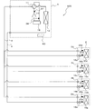
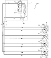
- FIG. 2 is a circuit configuration diagram showing an example of a circuit configuration of the refrigeration cycle apparatus (hereinafter referred to as the refrigeration cycle apparatus 100) according to Embodiment 1 of the present invention. Based on FIG. 2, the detailed structure of the refrigerating-cycle apparatus 100 is demonstrated. As shown in FIG. 2, the outdoor unit 1 and the indoor unit 2 are connected by an extension pipe (refrigerant pipe) 4 through which a refrigerant flows.
- extension pipe refrigerant pipe
- Outdoor unit 1 The outdoor unit 1 is mounted with a compressor 10, a first refrigerant flow switching device 11 such as a four-way valve, a heat source side heat exchanger 12, and an accumulator 19 connected in series by a refrigerant pipe.
- the compressor 10 sucks refrigerant and compresses the refrigerant to a high temperature and high pressure state.
- the compressor 10 may be composed of an inverter compressor capable of capacity control.
- the first refrigerant flow switching device 11 switches the refrigerant flow during the heating operation and the refrigerant flow during the cooling operation.
- the heat source side heat exchanger 12 functions as an evaporator during heating operation, and functions as a condenser (or radiator) during cooling operation.
- the heat source side heat exchanger 12 serving as the first heat exchanger performs heat exchange between air supplied from a blower (not shown) and the refrigerant, and evaporates or condenses the refrigerant. is there.
- the heat source side heat exchanger 12 acts as a condenser in the operation of cooling the indoor space 7. Moreover, in the case of the driving
- the accumulator 19 is provided on the suction side of the compressor 10 and stores excess refrigerant in the refrigerant circuit due to an operation mode change or the like.
- the outdoor unit 1 includes a compressor 10, a first refrigerant flow switching device 11, a heat source side heat exchanger 12, an accumulator 19, a high pressure detection device 37, a low pressure detection device 38, and a control device 60.
- the compressor 10 has, for example, a low-pressure shell structure that has a compression chamber in a sealed container, the inside of the sealed container has a low-pressure refrigerant pressure atmosphere, and sucks and compresses the low-pressure refrigerant in the sealed container.
- a high-pressure shell structure is used in which the inside of the sealed container becomes a high-pressure refrigerant pressure atmosphere and the high-pressure refrigerant compressed in the compression chamber is discharged into the sealed container.
- the outdoor unit 1 includes a control device 60, and controls devices based on detection information from various detection devices, instructions from a remote controller, and the like. For example, the driving frequency of the compressor 10, the rotation speed of the blower (including ON / OFF), the switching of the first refrigerant flow switching device 11 and the like are controlled, and each operation mode described later is executed.
- the control device 60 of the present embodiment is configured by a microcomputer or the like having control arithmetic processing means such as a CPU (Central Processing Unit). Moreover, it has a memory
- control arithmetic processing means executes processing based on the program data to realize control.
- the indoor unit 2 is equipped with a load-side heat exchanger 15 serving as a second heat exchanger.
- the load side heat exchanger 15 is connected to the outdoor unit 1 by the extension pipe 4.
- the load-side heat exchanger 15 exchanges heat between air supplied from a blower (not shown) and a refrigerant, and generates heating air or cooling air to be supplied to the indoor space 7. .
- the load side heat exchanger 15 acts as a condenser in the case of an operation for heating the indoor space 7. Moreover, in the case of the driving
- FIG. 2 shows an example in which four indoor units 2 are connected, and are illustrated as an indoor unit 2a, an indoor unit 2b, an indoor unit 2c, and an indoor unit 2d from the bottom of the page.
- the load side heat exchanger 15 is also loaded from the lower side of the page with the load side heat exchanger 15a, the load side heat exchanger 15b, the load side heat exchanger 15c, and the load side heat exchange. It is shown as a container 15d.
- the number of connected indoor units 2 is not limited to four as shown in FIG.
- the refrigeration cycle apparatus 100 determines the operation mode of the outdoor unit 1 to be either the cooling operation mode or the heating operation mode based on an instruction from each indoor unit 2. That is, the refrigeration cycle apparatus 100 can perform the same operation (cooling operation or heating operation) for all of the indoor units 2 and adjusts the indoor temperature. Note that each indoor unit 2 can be freely operated / stopped in both the cooling operation mode and the heating operation mode.
- the operation mode executed by the refrigeration cycle apparatus 100 includes a cooling operation mode in which all the driven indoor units 2 perform a cooling operation (including a stop), and all of the driven indoor units 2 are in a heating operation. There is a heating operation mode for executing (including stopping). Below, each operation mode is demonstrated with the flow of a refrigerant
- FIG. 3 is a refrigerant circuit diagram illustrating the refrigerant flow in the cooling operation mode when the discharge temperature of the refrigeration cycle apparatus 100 is low.
- the cooling operation mode will be described by taking as an example a case where a cooling load is generated in all the load-side heat exchangers 15.
- a pipe indicated by a thick line indicates a pipe through which the refrigerant flows, and a flow direction of the refrigerant is indicated by a solid line arrow.
- the first refrigerant flow switching device 11 is switched so that the refrigerant discharged from the compressor 10 flows into the heat source side heat exchanger 12.
- the low-temperature and low-pressure refrigerant is compressed by the compressor 10 and discharged as a high-temperature and high-pressure gas refrigerant.
- the high-temperature and high-pressure gas refrigerant discharged from the compressor 10 flows into the heat source side heat exchanger 12 via the first refrigerant flow switching device 11. Then, the heat source side heat exchanger 12 condenses and liquefies while radiating heat to the outdoor air, becomes a high-pressure liquid refrigerant, and flows out of the outdoor unit 1.
- the high-pressure liquid refrigerant that has flowed out of the outdoor unit 1 passes through the extension pipe 4 and flows into each of the indoor units 2 (2a to 2d).
- the high-pressure liquid refrigerant that has flowed into the indoor unit 2 (2a to 2d) flows into the expansion device 16 (16a to 16d), and is throttled and decompressed by the expansion device 16 (16a to 16d). It becomes a phase refrigerant. Further, it flows into each of the load side heat exchangers 15 (15a to 15d) acting as an evaporator, absorbs heat from the air circulating around the load side heat exchanger 15, and becomes a low-temperature and low-pressure gas refrigerant.
- the low-temperature and low-pressure gas refrigerant flows out of the indoor unit 2 (2a to 2d), flows into the outdoor unit 1 again through the extension pipe 4, passes through the first refrigerant flow switching device 11, and passes through the accumulator 19. Then, it is sucked into the compressor 10 again.
- the opening degree (opening area) of the expansion devices 16a to 16d is determined based on the detected temperature of the load-side heat exchanger gas refrigerant temperature detection device 28 and the control device 60 of each outdoor unit 2 from the control device 60 of the outdoor unit 1 (FIG. It is controlled so that the temperature difference (superheat degree) between the evaporation temperature transmitted by communication to the target value (not shown) approaches the target value.
- the cooling operation mode when executed, the operation is stopped because there is no need to flow the refrigerant to the load-side heat exchanger 15 (including the thermo-off) without the heat load.
- the expansion device 16 corresponding to the stopped indoor unit 2 is fully closed or set to a small opening at which the refrigerant does not flow.
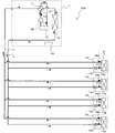
- FIG. 4 is a refrigerant circuit diagram illustrating a refrigerant flow when the refrigeration cycle apparatus 100 is in the heating operation mode.
- the heating operation mode will be described by taking as an example a case where a thermal load is generated in all the load side heat exchangers 15.
- a pipe indicated by a thick line indicates a pipe through which the refrigerant flows, and a flow direction of the refrigerant is indicated by a solid line arrow.
- the first refrigerant flow switching device 11 passes the refrigerant discharged from the compressor 10 to the indoor unit 2 without passing through the heat source side heat exchanger 12. Switch to allow inflow.
- the low-temperature and low-pressure refrigerant is compressed by the compressor 10 and discharged as a high-temperature and high-pressure gas refrigerant, passes through the first refrigerant flow switching device 11, and flows out of the outdoor unit 1.
- the high-temperature and high-pressure gas refrigerant that has flowed out of the outdoor unit 1 flows into each of the indoor units 2 (2a to 2d) through the extension pipe 4.
- the high-temperature and high-pressure liquid refrigerant that has flowed out of the load-side heat exchanger 15 (15a to 15d) flows into the expansion device 16 (16a to 16d), is throttled and decompressed by the expansion device 16 (16a to 16d), It becomes a low-pressure two-phase refrigerant and flows out of the indoor unit 2 (2a to 2d).
- the low-temperature and low-pressure two-phase refrigerant that has flowed out of the indoor unit 2 flows into the outdoor unit 1 again through the extension pipe 4.
- the opening degree (opening area) of the expansion devices 16a to 16d is determined based on the condensation temperature transmitted from the control device 60 of the outdoor unit 1 to the control device (not shown) of each indoor unit 2 through communication and the load side heat. Control is performed so that the temperature difference (degree of supercooling) from the detected temperature of the exchanger liquid refrigerant temperature detecting device 27 approaches the target value.
- the low-temperature and low-pressure two-phase refrigerant that has flowed into the outdoor unit 1 flows into the heat source side heat exchanger 12, absorbs heat from the air flowing around the heat source side heat exchanger 12, and evaporates to form a low-temperature and low-pressure gas refrigerant or low-temperature and low-pressure. It becomes a two-phase refrigerant with a large dryness.
- the low-temperature and low-pressure gas refrigerant or two-phase refrigerant is again sucked into the compressor 10 via the first refrigerant flow switching device 11 and the accumulator 19.
- the heating operation mode When the heating operation mode is executed, it is not necessary to flow the refrigerant to the load-side heat exchanger 15 (including the thermo-off) that has no heat load.
- the load-side heat exchanger 15 that is not in operation is set inside.
- the opening degree (opening area) of the expansion device 16 corresponding to the load-side heat exchanger 15 having no heat load is set to a large opening degree such as full opening to prevent accumulation of refrigerant.
- the first refrigerant flow switching device 11 generally uses a four-way valve. However, the first refrigerant flow switching device 11 is not limited to this and uses a plurality of two-way flow switching valves and a plurality of three-way flow switching valves. You may comprise so that a refrigerant
- coolant may flow into this.
- the accumulator 19 which stores an excess refrigerant
- [Type of refrigerant] When using a substance that is normally used as a refrigerant, such as R32, R410A, etc., as a refrigerant used in the refrigeration cycle apparatus 100, devise to improve the stability of the refrigerant in the refrigerant circuit. Without any problem, it can be used normally. However, here, the refrigerant causes a disproportionation reaction such as 1,1,2-trifluoroethylene (HFO-1123) represented by C 2 H 1 F 3 and having one double bond in the molecular structure. A single refrigerant composed of a substance having a property or a mixed refrigerant obtained by mixing another substance with a substance having a property causing a disproportionation reaction is used.
- a disproportionation reaction such as 1,1,2-trifluoroethylene (HFO-1123) represented by C 2 H 1 F 3
- CF 3 CF CH 2 HFO-1234yf which is 2,3,3,3-tetrafluoropropene, HFO-1234ze which is 1,3,3,3-tetrafluoro-1-propene represented by CF 3 CH ⁇ CHF), or Difluoromethane (HFC-32) whose chemical formula is represented by CH 2 F 2 is used.
- the substance to be mixed with the substance having a disproportionation reaction is not limited thereto, and HC-290 (propane) or the like may be mixed, and the thermal performance that can be used as the refrigerant of the refrigeration cycle apparatus 100 is improved. Any substance may be used as long as it has a substance. Further, the mixing ratio may be any mixing ratio.
- a substance having the property of causing a disproportionation reaction causes the following problems when used as a refrigerant as it is. That is, when a strong substance is applied in a place where there is a liquid state where the distance between adjacent substances is very close, such as a liquid phase, two phases, etc., the adjacent substances react with each other and become different substances. It will change and will not function as a refrigerant. In addition, there is a possibility that an accident such as a pipe rupture may occur due to a rapid pressure rise due to heat generation.
- a device that does not cause the disproportionation reaction in the liquid part or the two-phase part that is a mixed state of gas and liquid. Is required.
- the collision energy when the refrigerant and the structure collide also causes a disproportionation reaction of the refrigerant.
- the refrigerating machine oil filled in the refrigerant circuit is mainly composed of either polyol ester or polyvinyl ether, and a part of the refrigerating machine oil filled in the compressor 10 circulates in the refrigerant circuit together with the refrigerant.
- Both the polyol ester and the polyvinyl ether are refrigerating machine oils that are easily soluble in a refrigerant having one double bond in the molecular structure.
- Refrigerating machine oil is compatible with HFO1123, which is a refrigerant. Therefore, HFO-1123 is dissolved to some extent in refrigeration oil.
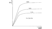
- FIG. 5 is a solubility diagram of the refrigerating machine oil of the refrigeration cycle apparatus according to Embodiment 1 of the present invention.
- High solubility means that many refrigerants are dissolved in the refrigeration oil
- low solubility means that only a small amount of refrigerant is dissolved in the refrigeration oil.
- FIG. 5 shows the relationship between the solubility and the pressure for each of the refrigerant temperatures T1, T2, and T3.
- T1, T2, and T3 are different temperatures, and the formula (1) is established.
- the refrigerant disproportionation reaction is a phenomenon in which molecules of adjacent refrigerants react with each other.
- the greater the solubility of the refrigerant in the refrigerating machine oil the greater the effect. Practically, if the solubility is 50 wt% (weight%) or more, many refrigerants are dissolved in the refrigerating machine oil, so that the disproportionation reaction can be suppressed.
- the refrigerant that has flowed into the load-side heat exchanger 15 (15a to 15d) condenses, liquefies through the two-phase region, and flows out from the load-side heat exchanger 15 (15a to 15d) as a high-temperature and high-pressure liquid refrigerant. .
- the high-temperature and high-pressure gas refrigerant flows into the heat source side heat exchanger 12 and condenses, liquefies through the two-phase region, and flows out as a high-temperature and high-pressure liquid refrigerant.
- the low-temperature and low-pressure two-phase refrigerant flows into the heat source side heat exchanger 12 and evaporates, and flows out as a low-temperature and low-pressure two-phase refrigerant having a large dryness.
- FIG. 6 is a schematic cross-sectional view of a configuration example in which grooving is performed on the inner surface (heat transfer surface) of the heat transfer tube used in the heat exchanger of the refrigeration cycle apparatus according to Embodiment 1 of the present invention.
- a flow path 42 through which a refrigerant flows.
- a plurality of grooves 43 extending in the tube axis direction are formed at intervals in the circumferential direction, and the inner surface of the heat transfer tube 41 is an uneven surface 43a.
- the refrigerant increases in flow velocity in the concave portion 43b of the uneven surface 43a in the heat transfer tube 41, and flows through the heat transfer tube 41 while repeatedly colliding with the convex portion 43c. Therefore, generally, when the groove is formed on the inner surface of the heat transfer tube 41, not only the heat transfer rate increases, but also the pressure loss of the refrigerant increases. Thus, the groove
- the groove 43 of the heat transfer tube 41 is often formed into a shape having a great effect of disturbing the flow of the refrigerant (for example, a spiral extending in the tube axis direction). In this case, the effect is further increased.
- FIG. 6 is an example of the groove processing, and is not limited to this shape.
- the groove 43 may not be spiral, and the uneven surface 43a is formed inside the heat transfer tube 41, so that the refrigerant As long as the flow is turbulent, the same situation will occur regardless of the shape.
- the groove processing is performed on the inner surface of the heat transfer tube 41, the disproportionation reaction of the refrigerant is likely to occur.
- the refrigerating machine oil having compatibility with the refrigerant is used, the refrigerant and the refrigerating machine oil are dissolved, Refrigerating machine oil molecules are present between the refrigerant molecules, which makes it difficult for the refrigerant to disproportionate.
- FIG. 7 is a schematic diagram of another heat transfer tube used in the heat exchanger of the refrigeration cycle apparatus according to Embodiment 1 of the present invention.
- FIG. 7 shows a flat tube having a flat channel structure in which the inside is divided into a plurality of (here, four) channels 42.
- the flat tube further has a groove 43 formed in each flow path 42 and has an uneven surface 43a on the inner surface.
- As the heat transfer tube 41 a flat tube having the flat flow channel structure shown in FIG. Even when a flat tube having such a flat flow channel structure is used, the refrigerant disproportionation reaction is unlikely to occur when a refrigerating machine oil having compatibility with the refrigerant is used, as in the case of using a circular tube. .
- the heat transfer tube 41 and the flow path 42 may have any shape, and have the same effect.
- the heat transfer tube 41 itself may be a smooth tube (circular tube) having a smooth inner surface, and may be configured to include other heat transfer promotion mechanisms such as inserting a helically formed torsion tube into the heat transfer tube 41. . In this case as well, the same can be said and the same effect is obtained.
- the frequency of the compressor 10 and the rotation speed of a blower (not shown) attached to the heat source side heat exchanger 12 are controlled, and the condenser is mainly used in the heating operation mode or the like.
- the condensation temperature which is the temperature of the refrigerant inside, is controlled to about 50 ° C.
- the expansion device 16 is controlled to control the degree of supercooling of the refrigerant at the outlet of the condenser to about 10 ° C. For this reason, if the condensation temperature is about 50 ° C., the temperature of the refrigerant at the outlet of the condenser is controlled to about 40 ° C.
- the two-phase refrigerant in the condenser is in a saturated pressure state where the temperature is about 50 ° C. and the pressure is about 50 ° C., and the temperature of the liquid refrigerant in the condenser increases as it approaches the outlet of the condenser.
- the pressure changes from about 50 ° C. to about 40 ° C., and the pressure is at a saturation pressure of about 50 ° C.
- the evaporation temperature which is the temperature of the refrigerant in the evaporator mainly in the cooling operation mode or the like. Is controlled at about 0 ° C. Further, the superheat degree of the refrigerant at the outlet of the evaporator is controlled to about 0 to 5 ° C. That is, most of the inside of the evaporator is in a two-phase state, and is in a saturated pressure state where the temperature is about 0 ° C. and the pressure is about 0 ° C.
- the heat transfer promoting mechanism is Even when passing through the heat transfer tube 41, the disproportionation reaction is unlikely to occur. It should be noted that the place where the liquid refrigerant or the two-phase refrigerant flows does not have to be the entire area of the flow path 42 of the heat transfer tube 41 of the heat exchanger (12 or 15).
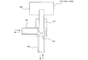
- FIG. 8 is a schematic diagram of the configuration of the expansion device of the refrigeration cycle apparatus according to Embodiment 1 of the present invention.
- the expansion device 16 (16a to 16d) includes a first connection pipe 44, a second connection pipe 45, a throttle section 46, a valve body 47, and a motor 48.
- the solid line arrow indicates the direction in which the refrigerant flows during the heating operation
- the broken line arrow indicates the direction in which the refrigerant flows during the cooling operation.
- the high-pressure liquid refrigerant or two-phase refrigerant that flows out of the outdoor unit 1 and flows into the indoor unit 2 flows into the expansion device 16 from the second connection pipe 45.
- the high-pressure liquid refrigerant or two-phase refrigerant that has flowed in from the second connection pipe 45 is squeezed and reduced in pressure by the valve body 47 inserted in the throttle part 46 in the throttle part 46, and becomes a low-temperature and low-pressure two-phase refrigerant.
- the low-temperature and low-pressure two-phase refrigerant flows out from the first connection pipe 44 and flows into the load-side heat exchanger 15 (15a to 15d).
- the first connection pipe 44 Into the expansion device 16.
- the high-pressure liquid refrigerant or two-phase refrigerant that has flowed in from the first connection pipe 44 is squeezed and reduced in pressure by the valve body 47 in the throttling portion 46 to become a low-temperature and low-pressure two-phase refrigerant.
- the low-temperature and low-pressure two-phase refrigerant flows out of the second connection pipe 45 and flows out of the indoor unit 2.
- the throttle amount of the refrigerant is controlled by changing the position of the valve body 47 (vertical direction position in FIG. 8) by the motor 48. That is, by changing the position of the valve body 47, the amount of insertion of the valve body 47 into the throttle part 46 changes, the area (opening area) of the gap between the throttle part 46 and the valve body 47 changes, and the refrigerant The aperture amount is controlled.
- the flow path cross-sectional area of the throttle 46 provided between the first connection pipe 44 and the second connection pipe 45 and through which the refrigerant flows is determined by the internal connection between the first connection pipe 44 and the second connection pipe 45. Smaller than the area.
- a stepping motor or the like is used as the motor 48 used in the expansion device 16, and the valve body 47 moves while rotating (up and down in FIG. 8), and a gap between the expansion portion 46 and the valve body 47.
- the area (opening area) is changed.
- the valve body 47 is often cylindrical.
- the cylindrical shape is easy to use as the valve body 47 of the expansion device 16 because the cross-sectional area does not change even if the valve body 47 is moved in the axial direction while rotating.
- the flow direction of the refrigerant flowing in from the first connection pipe 44 and the flow direction of the refrigerant flowing out of the second connection pipe 45 are substantially orthogonal to each other.
- the liquid state refrigerant or the two-phase state refrigerant collides with the cylindrical valve body 47 from the lateral direction (circumferential direction).
- the liquid refrigerant or the two-phase refrigerant collides with the cylindrical valve body 47 in the vertical direction (axial direction).
- the disproportionation reaction of the refrigerant may occur due to the collision energy generated when the refrigerant and the valve body 47 collide.
- the refrigerating machine oil having compatibility with the refrigerant is used, the refrigerant and the refrigerating machine oil are dissolved, and the refrigerating machine oil molecules exist between the refrigerant molecules. The refrigerant disproportionation reaction is difficult to occur.
- the throttle device 16 (16a to 16d) includes a direct-acting throttle device that directly drives the valve body 47 by the motor 48, and a gear type that has a gear interposed between the motor 48 and the valve body 47. There is an aperture device, either of which can be used. Further, the motor 48 is not limited to a stepping motor, and any motor may be used. The diaphragm device 16 is not limited to an electrically driven type, and may be a mechanical diaphragm device.
- the refrigerant in the condenser is controlled by controlling the frequency of the compressor 10 and the rotational speed of a blower (not shown) attached to the heat source side heat exchanger 12.
- the condensation temperature which is the temperature of Further, the expansion device 16 is controlled so that the degree of supercooling of the refrigerant at the outlet of the condenser is about 10 ° C. That is, if the condensation temperature is about 50 ° C., the temperature of the refrigerant at the outlet of the condenser is controlled to about 40 ° C. and flows out of the condenser. Therefore, the refrigerant flowing into the expansion device 16 is in a saturated pressure state where the temperature is about 40 ° C. and the pressure is 50 ° C.
- the refrigerant flowing into the expansion device 16 is in a state where the temperature is between about 40 to 50 ° C. and the saturation pressure is 50 ° C. Therefore, if the solubility of the refrigerant in the refrigerating machine oil is high at these temperatures and pressures, the refrigerant disproportionation reaction hardly occurs. Practically, in the state where the refrigerant is at these temperatures and pressures, if the solubility of the refrigerant in the refrigerating machine oil is 50 wt% (weight%) or more, many refrigerants are dissolved in the refrigerating machine oil, so disproportionation The reaction can be suppressed.
- the refrigerant at the time of flowing through the expansion device 16 has a solubility of 50 wt% (weight%) or more in the refrigerating machine oil and is dissolved in the refrigerating machine oil, even if it collides with the valve body 47, there is no problem. Leveling reaction is unlikely to occur.
- FIG. 9 is a schematic diagram of the configuration of the accumulator of the refrigeration cycle apparatus according to Embodiment 1 of the present invention.
- FIG. 9 is a side view of the inside of the accumulator 19 as viewed from the side.
- the accumulator 19 includes an inflow pipe 49, an outflow pipe 50, an oil return hole 51 provided in the outflow pipe 50, and a shell 52 of the accumulator 19. ing.
- the inflow pipe 49 and the outflow pipe 50 are structured to be inserted into the shell 52.
- the solid arrow indicates the direction in which the refrigerant flows, and the refrigerant flows into the shell 52 from the inflow pipe 49, opens to the shell 52, expands the volume, and then flows out from the outflow pipe 50.
- the inlet 50a of the outflow pipe 50 is located at a position higher than the outlet 49a of the inflow pipe 49, and the refrigerant flowing into the shell 52 from the inflow pipe 49 does not directly flow into the outflow pipe 50 due to inertial force and gravity.
- the oil return hole 51 provided in the outflow pipe 50 serves to return the refrigerant liquid accumulated in the refrigerating machine oil, which has accumulated under the shell 52, into the outflow pipe 50 and return the refrigerating machine oil to the compressor 10.
- high-temperature and high-pressure liquid refrigerant and low-temperature and low-pressure gas refrigerant flow through the extension pipe 4 connecting the outdoor unit 1 and the indoor unit 2 during the cooling operation. Further, during the heating operation, high-temperature and high-pressure gas refrigerant and two-phase refrigerant mixed with low-temperature and low-pressure gas and liquid flow through the extension pipe 4. Since the liquid refrigerant has a higher density than the gas refrigerant, the amount of refrigerant in the extension pipe 4 is larger during the cooling operation than during the heating operation. Therefore, surplus refrigerant is generated in the refrigerant circuit during heating operation.
- the inflow pipe 49 is inserted from above the shell 52 and bent sideways in the shell 52.
- the outlet 49 a of the inflow pipe 49 is disposed at a position slightly away from the inner wall surface 52 a of the shell 52 and not in contact with the inner wall surface 52 a of the shell 52.
- the refrigerant When the two-phase refrigerant flows from the inflow pipe 49 and collides with the inner wall surface 52a of the shell 52 of the accumulator 19, if a large collision energy is generated, the refrigerant may cause a disproportionation reaction. When surplus refrigerant is generated, a two-phase refrigerant having a dryness of 0.8 or more and 0.99 or less flows into the accumulator 19. Even in this case, if the refrigerating machine oil having compatibility with the refrigerant is used, the refrigerant disproportionation reaction is difficult to occur because the refrigerant oil molecules exist between the refrigerant molecules.
- the accumulator 19 may have a structure that is long in the horizontal direction and may have any shape.
- the frequency of the compressor 10 and the rotation speed of a blower (not shown) attached to the heat source side heat exchanger 12 are controlled, and the refrigerant in the evaporator
- the evaporation temperature which is the temperature
- the expansion device 16 is controlled to control the superheat degree of the refrigerant at the outlet of the evaporator to about 0 to 5 ° C. That is, the refrigerant flowing out of the evaporator and flowing into the accumulator 19 is in a saturated pressure state where the temperature is about 0 ° C. and the pressure is about 0 ° C.
- the solubility of the refrigerant in the refrigerating machine oil is large at this temperature and pressure, the disproportionation reaction of the refrigerant hardly occurs. Practically, in a state where the refrigerant is at this temperature and pressure, if the solubility of the refrigerant in the refrigerating machine oil is 50 wt% (weight%) or more, a large amount of the refrigerant dissolves in the refrigerating machine oil, and thus the disproportionation reaction Can be suppressed.
- the refrigerant at the time of flowing into the accumulator 19 has a solubility of 50 wt% (weight%) or more in the refrigerating machine oil and is dissolved in the refrigerating machine oil, even if it collides with the inner wall surface 52 a of the accumulator 19. , Disproportionation reaction is difficult to occur.
- Refrigerator oil also has a two-layer separation temperature.
- the refrigerant dissolves in the refrigerator oil when the temperature of the refrigerant is higher than the two-layer separation temperature.
- the refrigerant concentration is high, that is, a layer having a small amount of refrigeration oil and a layer having a high refrigeration oil concentration, that is, a layer having a low refrigerant concentration. Separated into layers.
- the refrigerant oil concentration is low in the layer where the refrigerant concentration is high, so that the disproportionation reaction of the refrigerant easily occurs due to collision energy or the like.
- the two-layer separation temperature should be as low as possible so that the two-layer separation does not occur within the operating range of the refrigeration cycle apparatus, and at least needs to be lower than the evaporation temperature.
- the evaporation temperature is controlled at 0 ° C.
- the two-layer separation temperature needs to be at least lower than 0 ° C.
- the heat source side heat exchanger 12 when acting as an evaporator, when the air temperature around the heat source side heat exchanger 12, that is, when the outside air temperature is low, the evaporation temperature is lower than 0 ° C.
- the two-layer separation temperature of the refrigerating machine oil is desirably lower than the evaporation temperature, and is required to be a temperature lower than 0 ° C.
- the refrigeration cycle apparatus 100 has several operation modes. In these operation modes, the refrigerant flows through the extension pipe 4 that connects the outdoor unit 1 and the indoor unit 2.
- the high pressure detection device 37 and the low pressure detection device 38 are installed to control the refrigeration cycle high pressure and low pressure to target values, but may be a temperature detection device that detects a saturation temperature.
- coolant flow path switching device 11 was shown as if it were a four-way valve, it is not restricted to this, It uses the two-way flow path switching valve and the three-way flow path switching valve similarly, You may comprise so that a refrigerant
- the heat source side heat exchanger 12 and the load side heat exchangers 15a to 15d are provided with a blower, and in many cases, condensation or evaporation is promoted by blowing, but this is not restrictive.
- a blower for example, as the load side heat exchangers 15a to 15d, a panel heater using radiation can be used, and as the heat source side heat exchanger 12, a water-cooled type that moves heat by water or antifreeze. Things can also be used. Any heat exchanger having a structure that can dissipate or absorb heat can be used.
- the indoor unit 2 can arbitrarily select one of a cooling operation and a heating operation, and the entire system can perform a mixed operation of the indoor unit 2 that performs the cooling operation and the indoor unit 2 that performs the heating operation.
- the present invention can also be applied to a refrigeration cycle apparatus and has the same effect.
- FIG. A second embodiment of the present invention will be described with reference to the drawings. In the following, the second embodiment will be described focusing on the differences from the first embodiment. Note that the modification applied in the configuration part of the first embodiment is also applied to the same configuration part of the second embodiment.
- FIG. 10 is a circuit configuration diagram of the refrigeration cycle apparatus according to Embodiment 2 of the present invention.
- a refrigeration cycle apparatus 100 shown in FIG. 10 includes a refrigerant circulation circuit A in which an outdoor unit 1 and a heat medium relay unit 3 as a relay are connected by an extension pipe 4 to circulate refrigerant.
- the refrigeration cycle apparatus 100 includes a heat medium circulation circuit B in which the heat medium converter 3 and the indoor unit 2 are connected by a pipe (heat medium pipe) 5 and a heat medium such as water or brine circulates.
- the heat medium relay unit 3 includes a load side heat exchanger 15a and a load side heat exchanger 15b that perform heat exchange between the refrigerant circulating in the refrigerant circuit A and the heat medium circulating in the heat medium circuit B.
- plate-type heat exchangers are used for the load-side heat exchanger 15a and the load-side heat exchanger 15b.
- the plate heat exchanger (12 or 15) a plurality of plates are stacked, and a flow path is formed between the plates. The refrigerant and the heat medium alternately flow in each flow path, The heat medium exchanges heat.
- a groove is provided on the surface of the plate, which is the heat transfer surface of the plate heat exchanger, and an uneven surface is formed as a heat transfer promotion mechanism for promoting heat transfer.
- the shape of the groove is various, but the shape is different from the groove 43 in the heat transfer tube 41 in the case of a plate fin tube type heat exchanger. However, it is the same in that the grooves are provided to disturb the flow of the refrigerant and improve the heat transfer coefficient, and the same can be said for the first embodiment. Therefore, when the refrigerating machine oil having compatibility with the refrigerant is used, the disproportionation reaction of the refrigerant hardly occurs.
- the grooves constituting the uneven surface may have any shape and have the same effect.
- the operation mode executed by the refrigeration cycle apparatus 100 includes a cooling only operation mode in which all the driven indoor units 2 execute a cooling operation and a heating operation in which all the driven indoor units 2 execute a heating operation. There is an operation mode. Further, there are a cooling main operation mode executed when the cooling load is larger and a heating main operation mode executed when the heating load is larger.
- the high-temperature and high-pressure gas refrigerant discharged from the compressor 10 flows into the heat source side heat exchanger 12 via the first refrigerant flow switching device 11 and dissipates heat to the surrounding air. It condenses and becomes high-pressure liquid refrigerant and flows out of the outdoor unit 1 through the check valve 13a. Then, it flows into the heat medium relay unit 3 through the extension pipe 4. The refrigerant flowing into the heat medium relay unit 3 passes through the opening / closing device 17a, expands in the expansion device 16a and the expansion device 16b, and becomes a low-temperature and low-pressure two-phase refrigerant.
- the two-phase refrigerant flows into each of the load side heat exchanger 15a and the load side heat exchanger 15b acting as an evaporator, absorbs heat from the heat medium circulating in the heat medium circuit B, and becomes a low-temperature and low-pressure gas refrigerant. .
- the gas refrigerant flows out of the heat medium relay unit 3 via the second refrigerant flow switching device 18a and the second refrigerant flow switching device 18b. Then, it flows into the outdoor unit 1 again through the extension pipe 4.
- the refrigerant flowing into the outdoor unit 1 passes through the check valve 13d and is sucked into the compressor 10 again via the first refrigerant flow switching device 11 and the accumulator 19.
- the heat medium is cooled by the refrigerant in both the load side heat exchanger 15a and the load side heat exchanger 15b.
- the cooled heat medium flows through the pipe 5 by the pump 21a and the pump 21b.
- the heat medium flowing into the use side heat exchangers 26a to 26d through the second heat medium flow switching devices 23a to 23d absorbs heat from the indoor air.
- the indoor air is cooled to cool the indoor space 7.
- the refrigerant that has flowed out of the use side heat exchangers 26a to 26d flows into the heat medium flow control devices 25a to 25d, passes through the first heat medium flow switching devices 22a to 22d, and passes through the load side heat exchanger 15a and the load side.
- the heat medium flow control devices 25a to 25d corresponding to the use side heat exchangers 26a to 26d without heat load are fully closed. Further, the heat medium flow control devices 25a to 25d corresponding to the use side heat exchangers 26a to 26d having the heat load adjust the opening degree to adjust the heat load in the use side heat exchangers 26a to 26d.
- the high-temperature and high-pressure gas refrigerant discharged from the compressor 10 flows out of the outdoor unit 1 through the first refrigerant flow switching device 11 and the first connection pipe 4a and the check valve 13b. To do. Then, it flows into the heat medium relay unit 3 through the extension pipe 4.
- the refrigerant that has flowed into the heat medium relay unit 3 flows into the load-side heat exchanger 15a and the load-side heat exchanger 15b through the second refrigerant flow switching device 18a and the second refrigerant flow switching device 18b, respectively.
- the heat is radiated to the heat medium circulating in the heat medium circuit B, and becomes a high-pressure liquid refrigerant.
- the high-pressure liquid refrigerant expands in the expansion device 16a and the expansion device 16b to become a low-temperature and low-pressure two-phase refrigerant, and flows out of the heat medium converter 3 through the opening / closing device 17b. Then, it flows into the outdoor unit 1 again through the extension pipe 4.
- the refrigerant flowing into the outdoor unit 1 passes through the second connection pipe 4b and the check valve 13c, flows into the heat source side heat exchanger 12 acting as an evaporator, absorbs heat from the surrounding air, and is a low-temperature and low-pressure gas refrigerant. It becomes.
- the gas refrigerant is again sucked into the compressor 10 via the first refrigerant flow switching device 11 and the accumulator 19.
- the operation of the heat medium in the heat medium circuit B is the same as in the cooling only operation mode.
- the heat medium is heated by the refrigerant in the load-side heat exchanger 15a and the load-side heat exchanger 15b, and is radiated to the indoor air in the use-side heat exchanger 26a and the use-side heat exchanger 26b.
- the indoor space 7 is heated.
- the high-temperature and high-pressure gas refrigerant discharged from the compressor 10 flows into the heat source side heat exchanger 12 via the first refrigerant flow switching device 11 and radiates and condenses to the surrounding air. Then, it becomes a two-phase refrigerant and flows out of the outdoor unit 1 through the check valve 13a. Then, it flows into the heat medium relay unit 3 through the extension pipe 4. The refrigerant flowing into the heat medium relay unit 3 flows into the load-side heat exchanger 15b acting as a condenser through the second refrigerant flow switching device 18b, and dissipates heat to the heat medium circulating in the heat medium circuit B. And high pressure liquid refrigerant.
- the high-pressure liquid refrigerant expands in the expansion device 16b and becomes a low-temperature and low-pressure two-phase refrigerant.
- the two-phase refrigerant flows into the load-side heat exchanger 15a acting as an evaporator through the expansion device 16a, absorbs heat from the heat medium circulating in the heat medium circuit B, and becomes a low-pressure gas refrigerant. It flows out of the heat medium relay unit 3 through the path switching device 18a. Then, it flows into the outdoor unit 1 again through the extension pipe 4.
- the refrigerant flowing into the outdoor unit 1 passes through the check valve 13d and is sucked into the compressor 10 again via the first refrigerant flow switching device 11 and the accumulator 19.
- the heat of the refrigerant is transmitted to the heat medium by the load side heat exchanger 15b.
- the heated heat medium flows in the pipe 5 by the pump 21b.
- the heat medium that has flowed into the use side heat exchangers 26a to 26d for which heating is requested by operating the first heat medium flow switching devices 22a to 22d and the second heat medium flow switching devices 23a to 23d radiates heat to the indoor air.
- the indoor air is heated to heat the indoor space 7.
- the cold heat of the refrigerant is transmitted to the heat medium in the load side heat exchanger 15a.
- the cooled heat medium flows through the pipe 5 by the pump 21a.
- the heat medium that has flowed into the use side heat exchangers 26a to 26d for which cooling is requested by operating the first heat medium flow switching devices 22a to 22d and the second heat medium flow switching devices 23a to 23d absorbs heat from the indoor air. To do.
- the indoor air is cooled to cool the indoor space 7.
- the heat medium flow control devices 25a to 25d corresponding to the use side heat exchangers 26a to 26d without heat load are fully closed.
- the heat medium flow control devices 25a to 25d corresponding to the use side heat exchangers 26a to 26d having the heat load adjust the opening degree to adjust the heat load in the use side heat exchangers 26a to 26d.
- Heating main operation mode In the heating main operation mode, the high-temperature and high-pressure gas refrigerant discharged from the compressor 10 passes through the first refrigerant flow switching device 11, passes through the first connection pipe 4 a and the check valve 13 b, and then the outdoor unit 1. Spill from. Then, it flows into the heat medium relay unit 3 through the extension pipe 4. The refrigerant flowing into the heat medium relay unit 3 flows into the load-side heat exchanger 15b acting as a condenser through the second refrigerant flow switching device 18b, and dissipates heat to the heat medium circulating in the heat medium circuit B. And high pressure liquid refrigerant.
- the high-pressure liquid refrigerant expands in the expansion device 16b and becomes a low-temperature and low-pressure two-phase refrigerant.
- the two-phase refrigerant flows into the load-side heat exchanger 15a acting as an evaporator via the expansion device 16a, absorbs heat from the heat medium circulating in the heat medium circuit B, and passes through the second refrigerant flow switching device 18a. And flows out of the heat medium relay unit 3. Then, it flows into the outdoor unit 1 again through the extension pipe 4.
- the refrigerant flowing into the outdoor unit 1 flows into the heat source side heat exchanger 12 acting as an evaporator through the second connection pipe 4b and the check valve 13c, absorbs heat from the surrounding air, and is a low-temperature and low-pressure gas.
- the gas refrigerant is again sucked into the compressor 10 via the first refrigerant flow switching device 11 and the accumulator 19.
- the operation of the heat medium in the heat medium circuit B, the first heat medium flow switching devices 22a to 22d, the second heat medium flow switching devices 23a to 23d, the heat medium flow control devices 25a to 25d, and the use side The operations of the heat exchangers 26a to 26d are the same as those in the cooling main operation mode.
- the first heat medium flow switching device 22 corresponding to the use side heat exchanger 26 performing the heating operation and The second heat medium flow switching device 23 is switched to a flow path connected to the load side heat exchanger 15b for heating. Further, the first heat medium flow switching device 22 and the second heat medium flow switching device 23 corresponding to the use side heat exchanger 26 performing the cooling operation are connected to the cooling load side heat exchanger 15a. Switch to the flow path. For this reason, in each indoor unit 2, heating operation and cooling operation can be performed freely.
- the first heat medium flow switching device 22 and the second heat medium flow switching device 23 are those that can switch a three-way flow path such as a three-way valve, and those that open and close a two-way flow path such as an on-off valve. What is necessary is just to switch a flow path, such as combining two.
- the first heat medium can be obtained by combining two things such as a stepping motor drive type mixing valve that can change the flow rate of the three-way flow path and two things that can change the flow rate of the two-way flow path such as an electronic expansion valve.
- the flow path switching device 22 and the second heat medium flow path switching device 23 may be used.
- the heat medium flow control device 25 may be installed as a control valve having a three-way flow path with a bypass pipe that bypasses the use-side heat exchanger 26 other than the two-way valve. Further, the heat medium flow control device 25 may be a stepping motor drive type that can control the flow rate flowing through the flow path, and may be a two-way valve or a device in which one end of the three-way valve is closed. Further, as the heat medium flow control device 25, a device that opens and closes a two-way flow path such as an open / close valve may be used, and the average flow rate may be controlled by repeating ON / OFF.
- first refrigerant flow switching device 11 and the second refrigerant flow switching device 18 are shown as if they were four-way valves.
- the present invention is not limited to this, and a two-way flow switching valve or a three-way flow switching is possible. A plurality of valves may be used so that the refrigerant flows in the same manner.
- the heat medium flow control device 25 is built in the heat medium converter 3
- the heat medium flow control device 25 is not limited thereto, and may be built in the indoor unit 2. 3 and the indoor unit 2 may be configured separately.
- the heat medium for example, brine (antifreeze), water, a mixture of brine and water, a mixture of water and an additive having a high anticorrosive effect, or the like can be used. Therefore, in the refrigeration cycle apparatus 100, even if the heat medium leaks into the indoor space 7 through the indoor unit 2, a highly safe heat medium is used, which contributes to an improvement in safety. Become.
- the heat source side heat exchanger 12 and the use side heat exchangers 26a to 26d are provided with a blower, and in many cases, condensation or evaporation is promoted by blowing, but this is not restrictive.
- a blower for example, as the use side heat exchangers 26a to 26d, a panel heater using radiation can be used.
- a water-cooled type that moves heat by water or antifreeze can also be used. Any structure that can dissipate or absorb heat can be used.
- the number of pumps 21a and 21b is not limited to one, and a plurality of small capacity pumps may be arranged in parallel.
- the compressor 10, the four-way valve (first refrigerant flow switching device) 11, and the heat source side heat exchanger 12 are accommodated in the outdoor unit 1, and the use side heat exchanger is configured to exchange heat between the air in the air-conditioning target space and the refrigerant.
- 26 is accommodated in the indoor unit 2
- the load-side heat exchanger 15 and the expansion device 16 are accommodated in the heat medium converter 3
- the outdoor unit 1 and the heat medium converter 3 are connected by the extension pipe 4 to form a refrigerant. Is circulated, and the heat medium is circulated by connecting the indoor unit 2 and the heat medium converter 3 with a set of two pipes 5 each, and the load-side heat exchanger 15 exchanges heat between the refrigerant and the heat medium.
- the system to be performed has been described by way of an example of a system that can perform a mixed operation of the indoor unit 2 that performs the cooling operation and the indoor unit 2 that performs the heating operation, but is not limited thereto.
- the outdoor unit 1 and the heat medium relay unit 3 described in the first embodiment can be combined and applied to a system that performs only a cooling operation or a heating operation in the indoor unit 2 and has the same effect.
- Heat source unit (outdoor unit), 2, 2a, 2b, 2c, 2d indoor unit, 3 heat medium converter (relay unit), 4 extension pipe (refrigerant pipe), 4a first connection pipe, 4b second connection pipe, 5 piping (heat medium piping), 6 outdoor space, 7 indoor space, 8 outdoor space such as the back of the ceiling and indoor space, 9 building, 10 compressor, 11 1st refrigerant flow switching device (Four-way valve), 12 heat source side heat exchanger (first heat exchanger), 13a, 13b, 13c, 13d check valve, 15, 15a, 15b, 15c, 15d load side heat exchanger (second heat Exchanger), 16, 16a, 16b, 16c, 16d throttle device, 17a, 17b switching device, 18, 18a, 18b second refrigerant flow switching device, 19 accumulator, 21a, 21b pump, 22, 22a, 22b, 22 22d, first heat medium flow switching device, 23, 23a, 23b, 23c, 23d, second heat medium flow switching device, 25, 25a, 25
Landscapes
- Engineering & Computer Science (AREA)
- Chemical & Material Sciences (AREA)
- Physics & Mathematics (AREA)
- Thermal Sciences (AREA)
- Mechanical Engineering (AREA)
- General Engineering & Computer Science (AREA)
- Chemical Kinetics & Catalysis (AREA)
- Organic Chemistry (AREA)
- Oil, Petroleum & Natural Gas (AREA)
- General Chemical & Material Sciences (AREA)
- Health & Medical Sciences (AREA)
- Emergency Medicine (AREA)
- Materials Engineering (AREA)
- Combustion & Propulsion (AREA)
- Power Engineering (AREA)
- Analytical Chemistry (AREA)
- Compression-Type Refrigeration Machines With Reversible Cycles (AREA)
- Lubricants (AREA)
Abstract
Description
本発明の実施の形態1について、図面に基づいて説明する。図1は、本発明の実施の形態1に係る冷凍サイクル装置の設置例を示す概略図である。図1に示す冷凍サイクル装置は、冷媒を循環させる冷媒回路を構成して冷媒による冷凍サイクルを利用することで、運転モードとして冷房モードあるいは暖房モードのいずれかを選択できるものである。ここで、本実施の形態の冷凍サイクル装置は、空調対象空間(室内空間7)の空気調和を行う空気調和装置を例として説明する。
室外機1には、圧縮機10と、四方弁等の第1冷媒流路切替装置11と、熱源側熱交換器12と、アキュムレータ19とが冷媒配管で直列に接続されて搭載されている。
室内機2には、それぞれ第二の熱交換器となる負荷側熱交換器15が搭載されている。この負荷側熱交換器15は、延長配管4によって室外機1に接続するようになっている。この負荷側熱交換器15は、図示省略の送風機から供給される空気と冷媒との間で熱交換を行い、室内空間7に供給するための暖房用空気あるいは冷房用空気を生成するものである。負荷側熱交換器15は、室内空間7を暖房する運転の場合には凝縮器として作用する。また、室内空間7を冷房する運転の場合には蒸発器として作用する。
図3は、冷凍サイクル装置100の吐出温度が低い場合の冷房運転モード時における冷媒の流れを示す冷媒回路図である。この図3では、全部の負荷側熱交換器15において冷熱負荷が発生している場合を例に冷房運転モードについて説明する。なお、図3では、太線で表された配管が冷媒の流れる配管を示しており、冷媒の流れ方向を実線矢印で示している。
図4は、冷凍サイクル装置100の暖房運転モード時における冷媒の流れを示す冷媒回路図である。この図4では、全部の負荷側熱交換器15において温熱負荷が発生している場合を例に暖房運転モードについて説明する。なお、図4では、太線で表された配管が冷媒の流れる配管を示しており、冷媒の流れ方向を実線矢印で示している。
冷凍サイクル装置100で使用する冷媒として、R32、R410A等のように、通常に冷媒として使用されている物質を使用する場合は、冷媒回路内での冷媒の安定性を改善するための工夫を施すことなく、このまま普通に使用すればよい。しかし、ここでは、冷媒として、C2H1F3で表され分子構造中に二重結合を1つ有する1,1,2-トリフルオロエチレン(HFO-1123)等の不均化反応を起こす性質の物質で構成した単一冷媒、または、不均化反応を起こす性質の物質に別の物質を混合させた混合冷媒を用いるものとする。
冷媒回路中に充填される冷凍機油は、ポリオールエステル及びポリビニルエーテルのうちいずれかを主成分とするものであり、圧縮機10に充填され冷凍機油の一部が冷媒と一緒に冷媒回路中を循環する。ポリオールエステル及びポリビニルエーテルは、いずれも、分子構造中に二重結合を1個有する冷媒に対して溶解しやすい相溶性を有する冷凍機油である。
T1<T2<T3 ・・・ (1)
冷凍サイクル装置100では、室内機2が冷房運転を行っている時は、負荷側熱交換器15(15a~15d)には低温低圧の二相冷媒が流入して蒸発ガス化し、低温低圧のガス冷媒となって負荷側熱交換器15(15a~15d)から流出する。また、室内機2が暖房運転を行っている時は、負荷側熱交換器15(15a~15d)には高温高圧のガス冷媒が流入する。負荷側熱交換器15(15a~15d)に流入した冷媒は、凝縮し、二相域を経て液化し、高温高圧の液冷媒となって負荷側熱交換器15(15a~15d)から流出する。
伝熱管41の内部は冷媒が流れる流路42となっている。伝熱管41の内面には、管軸方向に延びる溝43が周方向に間隔を空けて複数形成され、伝熱管41の内面が凹凸面43aとなっている。このように伝熱管41の内面に溝加工を施して凹凸面43aを形成すると、凹凸面43aの影響で冷媒の境界層が乱され、冷媒の乱れ度が増加する。
図7には、内部が複数(ここでは4つ)の流路42に分かれている扁平流路構造をした扁平管を示している。そして、この扁平管は更に、各流路42のそれぞれに溝43が形成されて内面に凹凸面43aを有している。伝熱管41に、図7に示した扁平流路構造の扁平管を使用してもよい。このような扁平流路構造をした扁平管を用いた場合も、円管を用いた場合と同様に、冷媒に対して相溶性を有する冷凍機油を用いると、冷媒の不均化反応が起き難い。また、伝熱管41及び流路42は、どのような形をしていてもよく、同様の効果を奏する。
図8は、本発明の実施の形態1に係る冷凍サイクル装置の絞り装置の構成の概略図である。図8において、絞り装置16(16a~16d)は、第1接続管44、第2接続管45、絞り部46、弁体47、及び、モーター48を備えている。図8において、実線矢印は暖房運転時に冷媒が流れる向きを示しており、破線矢印は冷房運転時に冷媒が流れる向きを示している。
図9は、本発明の実施の形態1に係る冷凍サイクル装置のアキュムレータの構成の概要図である。図9はアキュムレータ19の内部を側面から見た側面図であり、アキュムレータ19は、流入管49、流出管50、流出管50に設けられた油戻し穴51、及び、アキュムレータ19のシェル52を備えている。流入管49及び流出管50はシェル52に挿入された構造となっている。
以上説明したように、本実施の形態に係る冷凍サイクル装置100は、幾つかの運転モードを具備している。これらの運転モードにおいては、室外機1と室内機2とを接続する延長配管4には冷媒が流れている。
本発明の実施の形態2について、図面に基づいて説明する。以下、実施の形態2が実施の形態1と異なる部分を中心に説明する。なお、実施の形態1の構成部分において適用された変形例は、実施の形態2の同様の構成部分においても同様に適用される。
図10に示す冷凍サイクル装置100は、室外機1と中継器である熱媒体変換機3とが延長配管4で接続されて冷媒が循環する冷媒循環回路Aを備えている。また、冷凍サイクル装置100は、熱媒体変換機3と室内機2とが配管(熱媒体配管)5で接続されて、水やブライン等の熱媒体が循環する熱媒体循環回路Bを備えている。熱媒体変換機3は冷媒循環回路Aを循環する冷媒と、熱媒体循環回路Bを循環する熱媒体との熱交換を行う負荷側熱交換器15a及び負荷側熱交換器15bを備えている。
全冷房運転モードの場合、圧縮機10から吐出された高温高圧のガス冷媒は、第1冷媒流路切替装置11を介して、熱源側熱交換器12へ流入し、周囲の空気に放熱して凝縮液化し、高圧液冷媒となり、逆止弁13aを通って室外機1から流出する。そして、延長配管4を通って熱媒体変換機3に流入する。熱媒体変換機3に流入した冷媒は、開閉装置17aを通り、絞り装置16a及び絞り装置16bで膨張して低温低圧の二相冷媒となる。二相冷媒は、蒸発器として作用する負荷側熱交換器15a及び負荷側熱交換器15bのそれぞれに流入し、熱媒体循環回路Bを循環する熱媒体から吸熱し、低温低圧のガス冷媒となる。ガス冷媒は、第2冷媒流路切替装置18a及び第2冷媒流路切替装置18bを介して熱媒体変換機3から流出する。そして、延長配管4を通って再び室外機1へ流入する。室外機1へ流入した冷媒は、逆止弁13dを通って、第1冷媒流路切替装置11及びアキュムレータ19を介して、圧縮機10へ再度吸入される。
全暖房運転モードの場合、圧縮機10から吐出された高温高圧のガス冷媒は、第1冷媒流路切替装置11を介して第1接続配管4a、逆止弁13bを通り、室外機1から流出する。そして、延長配管4を通って熱媒体変換機3に流入する。熱媒体変換機3に流入した冷媒は、第2冷媒流路切替装置18a及び第2冷媒流路切替装置18bを通って、負荷側熱交換器15a及び負荷側熱交換器15bのそれぞれに流入し、熱媒体循環回路Bを循環する熱媒体に放熱し、高圧の液冷媒となる。高圧の液冷媒は、絞り装置16a及び絞り装置16bで膨張して低温低圧の二相冷媒となり、開閉装置17bを通って、熱媒体変換機3から流出する。そして、延長配管4を通って再び室外機1へ流入する。室外機1へ流入した冷媒は、第2接続配管4b及び逆止弁13cを通り、蒸発器として作用する熱源側熱交換器12に流入し、周囲の空気から吸熱して、低温低圧のガス冷媒となる。ガス冷媒は、第1冷媒流路切替装置11及びアキュムレータ19を介して圧縮機10へ再度吸入される。なお、熱媒体循環回路Bにおける熱媒体の動作は、全冷房運転モードの場合と同じである。全暖房運転モードでは、負荷側熱交換器15a及び負荷側熱交換器15bにおいて、熱媒体が冷媒によって加熱され、利用側熱交換器26a及び利用側熱交換器26bで室内空気に放熱して、室内空間7の暖房を行う。
冷房主体運転モードの場合、圧縮機10から吐出された高温高圧のガス冷媒は、第1冷媒流路切替装置11を介して熱源側熱交換器12に流入し、周囲の空気に放熱して凝縮し、二相冷媒となり、逆止弁13aを通って、室外機1から流出する。そして、延長配管4を通って熱媒体変換機3に流入する。熱媒体変換機3に流入した冷媒は、第2冷媒流路切替装置18bを通って凝縮器として作用する負荷側熱交換器15bに流入し、熱媒体循環回路Bを循環する熱媒体に放熱して高圧の液冷媒となる。高圧の液冷媒は、絞り装置16bで膨張して低温低圧の二相冷媒となる。二相冷媒は、絞り装置16aを介して蒸発器として作用する負荷側熱交換器15aに流入し、熱媒体循環回路Bを循環する熱媒体から吸熱して低圧のガス冷媒となり、第2冷媒流路切替装置18aを介して熱媒体変換機3から流出する。そして、延長配管4を通って再び室外機1へ流入する。室外機1へ流入した冷媒は、逆止弁13dを通って、第1冷媒流路切替装置11及びアキュムレータ19を介して、圧縮機10へ再度吸入される。
暖房主体運転モードの場合、圧縮機10から吐出された高温高圧のガス冷媒は、第1冷媒流路切替装置11を介して、第1接続配管4a及び逆止弁13bを通って、室外機1から流出する。そして、延長配管4を通って熱媒体変換機3に流入する。熱媒体変換機3に流入した冷媒は、第2冷媒流路切替装置18bを通って凝縮器として作用する負荷側熱交換器15bに流入し、熱媒体循環回路Bを循環する熱媒体に放熱して高圧の液冷媒となる。高圧の液冷媒は、絞り装置16bで膨張して低温低圧の二相冷媒となる。二相冷媒は、絞り装置16aを介して蒸発器として作用する負荷側熱交換器15aに流入し、熱媒体循環回路Bを循環する熱媒体から吸熱し、第2冷媒流路切替装置18aを介して熱媒体変換機3から流出する。そして、延長配管4を通って再び室外機1へ流入する。室外機1へ流入した冷媒は、第2接続配管4b及び逆止弁13cを通って、蒸発器として作用する熱源側熱交換器12に流入し、周囲の空気から吸熱して、低温低圧のガス冷媒となる。ガス冷媒は、第1冷媒流路切替装置11及びアキュムレータ19を介して圧縮機10へ再度吸入される。なお、熱媒体循環回路Bにおける熱媒体の動作、第1熱媒体流路切替装置22a~22d、第2熱媒体流路切替装置23a~23d、熱媒体流量調整装置25a~25d、及び、利用側熱交換器26a~26d、の動作は冷房主体運転モードと同一である。
冷媒の種類、熱交換器(12または26)、絞り装置16及びアキュムレータ19に関しては、実施の形態1と同様のものが適用でき、同様の効果を奏する。
本実施の形態における各運転モードにおいては、室外機1と熱媒体変換機3とを接続する延長配管4には冷媒が流れ、熱媒体変換機3と室内機2を接続する配管5には水や不凍液等の熱媒体が流れている。
Claims (19)
- 圧縮機と、第一の熱交換器と、絞り装置と、第二の熱交換器と、を冷媒配管で接続して構成された冷凍サイクルを備え、
前記冷凍サイクルには、不均化反応を起こす性質の物質で構成した単一冷媒または不均化反応を起こす性質の物質を含む混合冷媒と、前記冷媒に対して相溶性を有する冷凍機油と、が充填されている冷凍サイクル装置。 - 前記二層分離温度は0℃未満である請求項1に記載の冷凍サイクル装置。
- 前記冷凍機油は、前記冷媒の温度が50℃かつ前記冷媒の圧力が50℃の飽和圧力である状態において、前記冷媒の前記冷凍機油に対する溶解度が50重量%以上である請求項1または請求項2に記載の冷凍サイクル装置。
- 前記冷凍機油は、前記冷媒の温度が40℃かつ前記冷媒の圧力が50℃の飽和圧力である状態において、前記冷媒の前記冷凍機油に対する溶解度が50重量%以上である請求項1または請求項2に記載の冷凍サイクル装置。
- 前記冷凍機油は、前記冷媒の温度が0℃かつ前記冷媒の圧力が0℃の飽和圧力である状態において、前記冷媒の前記冷凍機油に対する溶解度が50重量%以上である請求項1または請求項2に記載の冷凍サイクル装置。
- 前記第一の熱交換器または前記第二の熱交換器が凝縮器または蒸発器として作用し、かつ、前記第一の熱交換器または前記第二の熱交換器の前記冷媒が流れる1つまたは複数の流路に、伝熱を促進するための伝熱促進機構を有する請求項1~請求項5のいずれか一項に記載の冷凍サイクル装置。
- 前記伝熱促進機構は、前記流路を形成する伝熱管の伝熱面に施した凹凸面である請求項6に記載の冷凍サイクル装置。
- 前記凹凸面の凹部は、螺旋状の溝である請求項7に記載の冷凍サイクル装置。
- 前記1つまたは複数の流路のいずれかの位置を、液状態の冷媒または二相状態の冷媒が流動する請求項6~請求項8のいずれか一項に記載の冷凍サイクル装置。
- 前記絞り装置は、2本の接続管と、前記2本の接続管の間に設けられ、前記2本の接続管の内断面積よりも断面積が小さく、かつ、前記冷媒が流通する絞り部と、前記絞り部に挿入され、前記絞り部の流路の開口面積を変化させる弁体と、を有する請求項1~請求項9のいずれか一項に記載の冷凍サイクル装置。
- 前記絞り装置は、前記弁体が回転して前記開口面積を変化させる構造となっている請求項10に記載の冷凍サイクル装置。
- 前記弁体に、液状態の冷媒または二相状態の冷媒を流入させる請求項10または請求項11に記載の冷凍サイクル装置。
- 前記絞り装置に流入する冷媒の流れ方向は、前記第二の熱交換器を凝縮器として作用させる場合と前記第二の熱交換器を蒸発器として作用させる場合とで反転する請求項10~請求項12のいずれか一項に記載の冷凍サイクル装置。
- 前記圧縮機の吸入側に冷媒を貯留するアキュムレータを有し、前記アキュムレータは、前記冷媒を流入させる流入管を有し、前記流入管の出口が、前記アキュムレータの内壁面と接していない位置に、前記アキュムレータの内壁面に向けて設置されている請求項1~請求項13のいずれか一項に記載の冷凍サイクル装置。
- 前記アキュムレータに、二相状態の冷媒を流入させる運転状態を有する請求項14に記載の冷凍サイクル装置。
- 前記アキュムレータに、乾き度0.8以上かつ0.99以下の二相状態の冷媒を流入させる運転状態を有する請求項15に記載の冷凍サイクル装置。
- 前記不均化反応を起こす性質の物質は、1,1,2-トリフルオロエチレンである請求項1~請求項16のいずれか一項に記載の冷凍サイクル装置。
- 前記冷凍機油は、ポリオールエステル及びポリビニルエーテルのうちいずれかを主成分とする請求項1~請求項17のいずれか一項に記載の冷凍サイクル装置。
- 圧縮機と、第一の熱交換器と、絞り装置と、第二の熱交換器と、を冷媒配管で接続して構成された冷凍サイクルを備え、
前記冷凍サイクルには、1,1,2-トリフルオロエチレンで構成した単一冷媒または1,1,2-トリフルオロエチレンを含む混合冷媒と、前記冷媒に対して相溶性を示す冷凍機油とが充填され、
前記冷凍機油は、ポリオールエステル及びポリビニルエーテルのうちいずれかを主成分とし、前記冷凍機油の二層分離温度は0℃未満であり、
前記第一の熱交換器、前記第二の熱交換器及び前記絞り装置のうち少なくともいずれか一つに液状態の前記冷媒または二相状態の前記冷媒が流通し、その流通中の前記液状態の冷媒または前記二相状態の前記冷媒、の前記冷凍機油に対する溶解度が50重量%以上である冷凍サイクル装置。
Priority Applications (5)
| Application Number | Priority Date | Filing Date | Title |
|---|---|---|---|
| EP14886641.1A EP3121537A1 (en) | 2014-03-17 | 2014-03-17 | Refrigeration cycle apparatus |
| CN201480075131.4A CN105980791A (zh) | 2014-03-17 | 2014-03-17 | 制冷循环装置 |
| US15/116,045 US20170089616A1 (en) | 2014-03-17 | 2014-03-17 | Refrigeration cycle apparatus |
| JP2016508345A JPWO2015140885A1 (ja) | 2014-03-17 | 2014-03-17 | 冷凍サイクル装置 |
| PCT/JP2014/057047 WO2015140885A1 (ja) | 2014-03-17 | 2014-03-17 | 冷凍サイクル装置 |
Applications Claiming Priority (1)
| Application Number | Priority Date | Filing Date | Title |
|---|---|---|---|
| PCT/JP2014/057047 WO2015140885A1 (ja) | 2014-03-17 | 2014-03-17 | 冷凍サイクル装置 |
Publications (1)
| Publication Number | Publication Date |
|---|---|
| WO2015140885A1 true WO2015140885A1 (ja) | 2015-09-24 |
Family
ID=54143911
Family Applications (1)
| Application Number | Title | Priority Date | Filing Date |
|---|---|---|---|
| PCT/JP2014/057047 Ceased WO2015140885A1 (ja) | 2014-03-17 | 2014-03-17 | 冷凍サイクル装置 |
Country Status (5)
| Country | Link |
|---|---|
| US (1) | US20170089616A1 (ja) |
| EP (1) | EP3121537A1 (ja) |
| JP (1) | JPWO2015140885A1 (ja) |
| CN (1) | CN105980791A (ja) |
| WO (1) | WO2015140885A1 (ja) |
Cited By (4)
| Publication number | Priority date | Publication date | Assignee | Title |
|---|---|---|---|---|
| JPWO2016059698A1 (ja) * | 2014-10-16 | 2017-04-27 | 三菱電機株式会社 | 冷凍サイクル装置 |
| JP2019163907A (ja) * | 2018-03-20 | 2019-09-26 | 三菱電機株式会社 | 空気調和装置及び空気調和システム |
| WO2020066015A1 (ja) | 2018-09-28 | 2020-04-02 | 三菱電機株式会社 | 空気調和機 |
| JPWO2022114137A1 (ja) * | 2020-11-30 | 2022-06-02 |
Families Citing this family (3)
| Publication number | Priority date | Publication date | Assignee | Title |
|---|---|---|---|---|
| CN110494703A (zh) * | 2017-03-31 | 2019-11-22 | 大金工业株式会社 | 空调装置 |
| JP2018194200A (ja) * | 2017-05-15 | 2018-12-06 | パナソニックIpマネジメント株式会社 | 冷凍サイクル装置およびそれを備えた液体循環装置 |
| IT202300016458A1 (it) * | 2023-08-02 | 2025-02-02 | Cimberio Holding S P A | Sistema valvolare antigelo |
Citations (8)
| Publication number | Priority date | Publication date | Assignee | Title |
|---|---|---|---|---|
| JP2009191212A (ja) * | 2008-02-15 | 2009-08-27 | Idemitsu Kosan Co Ltd | 冷凍機用潤滑油組成物 |
| JP2009257741A (ja) * | 2008-03-25 | 2009-11-05 | Daikin Ind Ltd | 冷凍装置 |
| JP2010025418A (ja) * | 2008-07-17 | 2010-02-04 | Daikin Ind Ltd | 冷凍装置 |
| JP2012131994A (ja) * | 2010-11-30 | 2012-07-12 | Jx Nippon Oil & Energy Corp | 冷凍機用作動流体組成物および冷凍機油 |
| WO2012157764A1 (ja) * | 2011-05-19 | 2012-11-22 | 旭硝子株式会社 | 作動媒体および熱サイクルシステム |
| WO2013051059A1 (ja) * | 2011-10-04 | 2013-04-11 | 三菱電機株式会社 | 冷凍サイクル装置 |
| JP2013124800A (ja) * | 2011-12-14 | 2013-06-24 | Panasonic Corp | 冷凍サイクル装置 |
| JP2013210184A (ja) * | 2008-04-01 | 2013-10-10 | Honeywell Internatl Inc | 熱伝達回路への油戻り率を改善する方法 |
Family Cites Families (2)
| Publication number | Priority date | Publication date | Assignee | Title |
|---|---|---|---|---|
| DE69838912D1 (de) * | 1997-08-11 | 2008-02-07 | Ebara Corp | Hydrothermisches elektrolytisches verfahren und vorrichtung |
| WO2000047519A1 (fr) * | 1999-02-10 | 2000-08-17 | Ebara Corporation | Procede et appareil de traitement de milieu aqueux |
-
2014
- 2014-03-17 JP JP2016508345A patent/JPWO2015140885A1/ja active Pending
- 2014-03-17 WO PCT/JP2014/057047 patent/WO2015140885A1/ja not_active Ceased
- 2014-03-17 CN CN201480075131.4A patent/CN105980791A/zh not_active Withdrawn
- 2014-03-17 EP EP14886641.1A patent/EP3121537A1/en not_active Withdrawn
- 2014-03-17 US US15/116,045 patent/US20170089616A1/en not_active Abandoned
Patent Citations (8)
| Publication number | Priority date | Publication date | Assignee | Title |
|---|---|---|---|---|
| JP2009191212A (ja) * | 2008-02-15 | 2009-08-27 | Idemitsu Kosan Co Ltd | 冷凍機用潤滑油組成物 |
| JP2009257741A (ja) * | 2008-03-25 | 2009-11-05 | Daikin Ind Ltd | 冷凍装置 |
| JP2013210184A (ja) * | 2008-04-01 | 2013-10-10 | Honeywell Internatl Inc | 熱伝達回路への油戻り率を改善する方法 |
| JP2010025418A (ja) * | 2008-07-17 | 2010-02-04 | Daikin Ind Ltd | 冷凍装置 |
| JP2012131994A (ja) * | 2010-11-30 | 2012-07-12 | Jx Nippon Oil & Energy Corp | 冷凍機用作動流体組成物および冷凍機油 |
| WO2012157764A1 (ja) * | 2011-05-19 | 2012-11-22 | 旭硝子株式会社 | 作動媒体および熱サイクルシステム |
| WO2013051059A1 (ja) * | 2011-10-04 | 2013-04-11 | 三菱電機株式会社 | 冷凍サイクル装置 |
| JP2013124800A (ja) * | 2011-12-14 | 2013-06-24 | Panasonic Corp | 冷凍サイクル装置 |
Cited By (8)
| Publication number | Priority date | Publication date | Assignee | Title |
|---|---|---|---|---|
| JPWO2016059698A1 (ja) * | 2014-10-16 | 2017-04-27 | 三菱電機株式会社 | 冷凍サイクル装置 |
| JP2019163907A (ja) * | 2018-03-20 | 2019-09-26 | 三菱電機株式会社 | 空気調和装置及び空気調和システム |
| WO2020066015A1 (ja) | 2018-09-28 | 2020-04-02 | 三菱電機株式会社 | 空気調和機 |
| US11802724B2 (en) | 2018-09-28 | 2023-10-31 | Mitsubishi Electric Corporation | Air-conditioning apparatus with simultaneous heating and defrosting modes |
| JPWO2022114137A1 (ja) * | 2020-11-30 | 2022-06-02 | ||
| WO2022114137A1 (ja) * | 2020-11-30 | 2022-06-02 | Eneos株式会社 | 作動流体、冷凍機及び冷凍機油 |
| US12344809B2 (en) | 2020-11-30 | 2025-07-01 | Eneos Corporation | Working fluid, freezer, and freezer oil |
| JP7809649B2 (ja) | 2020-11-30 | 2026-02-02 | Eneos株式会社 | 作動流体、冷凍機及び冷凍機油 |
Also Published As
| Publication number | Publication date |
|---|---|
| CN105980791A (zh) | 2016-09-28 |
| EP3121537A1 (en) | 2017-01-25 |
| JPWO2015140885A1 (ja) | 2017-04-06 |
| US20170089616A1 (en) | 2017-03-30 |
Similar Documents
| Publication | Publication Date | Title |
|---|---|---|
| JP5657030B2 (ja) | 空気調和装置 | |
| JP5730335B2 (ja) | 空気調和装置 | |
| JP5465333B2 (ja) | 室外機および空気調和装置 | |
| JP5602243B2 (ja) | 空気調和機 | |
| JP5279919B2 (ja) | 空気調和装置 | |
| JP5236080B2 (ja) | 空気調和装置 | |
| WO2015140886A1 (ja) | 冷凍サイクル装置 | |
| JP5837099B2 (ja) | 空気調和装置 | |
| WO2015140887A1 (ja) | 冷凍サイクル装置 | |
| WO2011030430A1 (ja) | 空気調和装置 | |
| JP5523470B2 (ja) | 空気調和装置 | |
| WO2015140885A1 (ja) | 冷凍サイクル装置 | |
| WO2013069043A1 (ja) | 空気調和装置 | |
| JPWO2016009565A1 (ja) | 冷凍サイクル装置 | |
| JP5312606B2 (ja) | 空気調和装置 | |
| WO2013111180A1 (ja) | 空気調和装置の冷媒充填方法、空気調和装置 | |
| WO2015140878A1 (ja) | アキュムレータ及び冷凍サイクル装置 | |
| JPWO2016038659A1 (ja) | 冷凍サイクル装置 | |
| JPWO2015140881A1 (ja) | 冷凍サイクル装置 | |
| JPWO2016016999A1 (ja) | 冷凍サイクル装置 | |
| JPWO2015140877A1 (ja) | 絞り装置及び冷凍サイクル装置 | |
| JPWO2013111180A1 (ja) | 空気調和装置の冷媒充填方法、空気調和装置 |
Legal Events
| Date | Code | Title | Description |
|---|---|---|---|
| 121 | Ep: the epo has been informed by wipo that ep was designated in this application |
Ref document number: 14886641 Country of ref document: EP Kind code of ref document: A1 |
|
| WWE | Wipo information: entry into national phase |
Ref document number: 15116045 Country of ref document: US |
|
| ENP | Entry into the national phase |
Ref document number: 2016508345 Country of ref document: JP Kind code of ref document: A |
|
| REEP | Request for entry into the european phase |
Ref document number: 2014886641 Country of ref document: EP |
|
| WWE | Wipo information: entry into national phase |
Ref document number: 2014886641 Country of ref document: EP |
|
| NENP | Non-entry into the national phase |
Ref country code: DE |