WO2015137687A1 - 단말 간 통신을 지원하는 무선 통신 시스템에서 자원 할당 방법 및 이를 위한 장치 - Google Patents

단말 간 통신을 지원하는 무선 통신 시스템에서 자원 할당 방법 및 이를 위한 장치 Download PDF

Info

Publication number
WO2015137687A1
WO2015137687A1 PCT/KR2015/002279 KR2015002279W WO2015137687A1 WO 2015137687 A1 WO2015137687 A1 WO 2015137687A1 KR 2015002279 W KR2015002279 W KR 2015002279W WO 2015137687 A1 WO2015137687 A1 WO 2015137687A1
Authority
WO
WIPO (PCT)
Prior art keywords
terminal
resource
information
base station
scheduling
Prior art date
Application number
PCT/KR2015/002279
Other languages
English (en)
French (fr)
Inventor
김학성
강길모
신오순
신요안
Original Assignee
엘지전자(주)
숭실대학교산학협력단
Priority date (The priority date is an assumption and is not a legal conclusion. Google has not performed a legal analysis and makes no representation as to the accuracy of the date listed.)
Filing date
Publication date
Application filed by 엘지전자(주), 숭실대학교산학협력단 filed Critical 엘지전자(주)
Priority to KR1020167021217A priority Critical patent/KR20160110959A/ko
Priority to US15/125,127 priority patent/US20160381690A1/en
Publication of WO2015137687A1 publication Critical patent/WO2015137687A1/ko

Links

Classifications

    • HELECTRICITY
    • H04ELECTRIC COMMUNICATION TECHNIQUE
    • H04LTRANSMISSION OF DIGITAL INFORMATION, e.g. TELEGRAPHIC COMMUNICATION
    • H04L5/00Arrangements affording multiple use of the transmission path
    • H04L5/003Arrangements for allocating sub-channels of the transmission path
    • H04L5/0037Inter-user or inter-terminal allocation
    • HELECTRICITY
    • H04ELECTRIC COMMUNICATION TECHNIQUE
    • H04LTRANSMISSION OF DIGITAL INFORMATION, e.g. TELEGRAPHIC COMMUNICATION
    • H04L5/00Arrangements affording multiple use of the transmission path
    • H04L5/0001Arrangements for dividing the transmission path
    • H04L5/0003Two-dimensional division
    • H04L5/0005Time-frequency
    • H04L5/0007Time-frequency the frequencies being orthogonal, e.g. OFDM(A), DMT
    • H04L5/001Time-frequency the frequencies being orthogonal, e.g. OFDM(A), DMT the frequencies being arranged in component carriers
    • HELECTRICITY
    • H04ELECTRIC COMMUNICATION TECHNIQUE
    • H04LTRANSMISSION OF DIGITAL INFORMATION, e.g. TELEGRAPHIC COMMUNICATION
    • H04L5/00Arrangements affording multiple use of the transmission path
    • H04L5/003Arrangements for allocating sub-channels of the transmission path
    • H04L5/0053Allocation of signaling, i.e. of overhead other than pilot signals
    • H04L5/0055Physical resource allocation for ACK/NACK
    • HELECTRICITY
    • H04ELECTRIC COMMUNICATION TECHNIQUE
    • H04WWIRELESS COMMUNICATION NETWORKS
    • H04W72/00Local resource management
    • H04W72/04Wireless resource allocation
    • H04W72/044Wireless resource allocation based on the type of the allocated resource
    • H04W72/0453Resources in frequency domain, e.g. a carrier in FDMA
    • HELECTRICITY
    • H04ELECTRIC COMMUNICATION TECHNIQUE
    • H04WWIRELESS COMMUNICATION NETWORKS
    • H04W72/00Local resource management
    • H04W72/12Wireless traffic scheduling
    • H04W72/1263Mapping of traffic onto schedule, e.g. scheduled allocation or multiplexing of flows
    • HELECTRICITY
    • H04ELECTRIC COMMUNICATION TECHNIQUE
    • H04WWIRELESS COMMUNICATION NETWORKS
    • H04W72/00Local resource management
    • H04W72/12Wireless traffic scheduling
    • H04W72/1263Mapping of traffic onto schedule, e.g. scheduled allocation or multiplexing of flows
    • H04W72/1268Mapping of traffic onto schedule, e.g. scheduled allocation or multiplexing of flows of uplink data flows
    • HELECTRICITY
    • H04ELECTRIC COMMUNICATION TECHNIQUE
    • H04WWIRELESS COMMUNICATION NETWORKS
    • H04W72/00Local resource management
    • H04W72/50Allocation or scheduling criteria for wireless resources
    • H04W72/54Allocation or scheduling criteria for wireless resources based on quality criteria
    • H04W72/541Allocation or scheduling criteria for wireless resources based on quality criteria using the level of interference

Definitions

  • the present invention relates to a wireless communication system, and more particularly, to a wireless communication system in which a resource for D2D communication based on interference measured in a wireless communication system supporting ' D2 (Device-to-Device) And a device supporting the same.
  • the mobile communication system has been developed to provide voice service while ensuring the user 's activity.
  • the mobile communication system not only the voice but also the data service are extended.
  • due to the increase of the explosive traffic there is a shortage of resources and users require higher speed service, have.
  • next generation mobile communication system The requirements of the next generation mobile communication system are largely explosive data. It should be capable of accepting traffic, increasing the transmission rate per user, accepting a significantly increased number of connected devices, very low end-to-end latency, and high energy efficiency.
  • a dual connectivity a massive multiple input multiple output (MIMO), an in-band full duplex, a non-orthogonal multiple access (NOMA) Super wideband support, and Device Networking.
  • MIMO massive multiple input multiple output
  • NOMA non-orthogonal multiple access
  • a method of allocating resources for D2D communication in a wireless communication system supporting D2D (Device-to-Device) communication comprising the steps of: receiving, from the D2 D receiving terminal, least shared resource and resource search time information, allocating all or some of the same resources between the UE and the D2D receiving terminal, And synchronizing the scheduling in order to perform the scheduling.
  • a base station allocating resources for D2 D communication in a wireless communication system supporting D2D (Device-to-Device) communication, the base station comprising: a radio frequency (RF) unit for transmitting /
  • the processor receives from the D2 D receiving terminal the shared resource and resource search time information with the least interference from the neighboring terminal discovered by the D2 D receiving terminal, And may be configured to synchronize scheduling to allocate all or some of the same resources between the UE and the D2D receiving terminal in a scheduled cell.
  • the synchronizing of the scheduling may allocate all or a part of resources allocated to the UE to the D2 D receiving terminal at every scheduling period.
  • the step of synchronizing the scheduling may fix the resources allocated to the UE and allocate all or a part of the same resources to the D2 D receiving terminal.
  • the base station transmits the shared resource and resource rediscovery time information having the least interference re-searched by the D2D receiving terminal remind From the D2D receiving terminal.
  • the base station may further comprise transmitting the synchronized scheduling information to the UE and the D2D UE through the cell.
  • the synchronized scheduling information may include all or some of the same resource allocation information, or terminal identifier pairing information between the D2D terminal and the terminal. '
  • the base station may further comprise the step of buffering uplink scheduling information to the mobile station for a predetermined period of time.
  • a method of allocating resources for D2D communication in a wireless communication system supporting D2D (Device-to-Device) communication wherein the D2D receiving terminal transmits the shared resource information and the resource search time information to the base station and the D2D receiving terminal receives the scaling information from the base station,
  • the scheduling can be synchronized in order to allocate all or some of the same resources between the UE and the D2D receiving terminal while the shared resources are scheduled.
  • a D2D receiving terminal to which a resource for D2D communication is allocated in a wireless communication system supporting D2D (Device-to-Device) communication
  • a processor configured to search for a shared resource having the least interference from a neighboring terminal, transmit the shared resource information and resource search time information to the base station, and receive the scheduling information from the base station, Scheduling may be synchronized in order to allocate all or some of the same resources between the UE and the D2D receiving terminal while the shared resource is scheduled in the search time.
  • all or a portion of the resources allocated to the leaf node at each scheduling period may be allocated to the D2D receiving terminal.
  • the resources allocated to the leaf terminal are fixed, and all or a part of the same resources of the fixed resources may be allocated to the D2D receiving terminal.
  • the D2D receiving terminal transmits a D2D signal from the D2D transmitting terminal in advance And when the D2 D receiving terminal fails to receive the predetermined number of times or more, the D2 D receiving terminal may search for a shared resource having the least interference from the neighboring terminal.
  • the D2 D receiving terminal may further include transmitting the re-searched shared resource information and resource re-searching time information to the base station.
  • FIG. 1 shows a structure of a radio frame in a wireless communication system to which the present invention can be applied.
  • FIG. 2 is a diagram illustrating a resource grid for one downlink slot in a wireless communication system to which the present invention can be applied.
  • FIG 3 illustrates a structure of a downlink subframe in a wireless communication system to which the present invention can be applied.
  • FIG. 4 illustrates a structure of a UL subframe in a wireless communication system to which the present invention can be applied.
  • FIG. 5 shows an example of a form in which PUCCH formats are mapped to a PUCCH region of an uplink physical resource block in a wireless communication system to which the present invention can be applied.
  • 6 shows a structure of a CQI channel in a case of a general CP in a wireless communication system to which the present invention can be applied.
  • 7 shows a structure of an ACK / NACK channel in a case of a general CP in a wireless communication system to which the present invention can be applied.
  • FIG. 8 illustrates an example of generating and transmitting five SC-FDMA symbols during one slot in a wireless communication system to which the present invention can be applied.
  • FIG. 9 shows an example of component carriers and carrier merging in a wireless communication system to which the present invention may be applied.
  • FIG. 10 shows an example of a subframe structure according to cross carrier scheduling in a wireless communication system to which the present invention can be applied.
  • FIG. 11 shows an example of transmission channel processing of UL-SCH in a wireless communication system to which the present invention can be applied.
  • FIG. 12 shows an example of a signal processing process of an uplink shared channel, which is a transport channel in a wireless communication system to which the present invention can be applied.
  • 13 is a configuration diagram of a general MIMO communication system.
  • 14 is a diagram illustrating a channel from a plurality of transmission antennas to one reception antenna.
  • FIG. 15 illustrates a reference signal pattern mapped to a downlink resource block pair in a wireless communication system to which the present invention can be applied.
  • FIG. 16 illustrates an uplink subframe including a sounding reference signal symbol in a wireless communication system to which the present invention can be applied.
  • FIG. 18 is a diagram for conceptually illustrating D2 D communication in a wireless communication system to which the present invention can be applied.
  • 20 is a diagram illustrating a resource allocation method of D2 D communication in a cell-to-cell network.
  • FIG. 21 is a diagram illustrating the magnitude of interference according to the distance of a terminal from a D2 D terminal according to an embodiment of the present invention.
  • FIG. 22 is a diagram illustrating an example of a transmission between an uplink resource allocation (UL grant) and an uplink data transmission (PUSCH) in an FDD-based wireless communication system to which the present invention can be applied.
  • UL grant uplink resource allocation
  • PUSCH uplink data transmission
  • FIG. 23 is a diagram illustrating all of the resource allocation methods for D2 D communication according to an embodiment of the present invention.
  • 24 is a diagram illustrating a resource allocation method and a D2 D signal transmission method for D2 D communication according to an embodiment of the present invention.
  • 25 is a diagram illustrating a resource allocation method for D2 D communication according to an embodiment of the present invention.
  • 26 is a diagram illustrating a resource allocation method for D2 D communication according to an embodiment of the present invention.
  • FIG. 27 illustrates simulation results of a resource allocation method for D2 D communication according to an embodiment of the present invention.
  • 29 illustrates simulation results of a resource allocation method for D2 D communication according to an embodiment of the present invention.
  • FIG. 30 illustrates a block diagram of a wireless communication apparatus according to an embodiment of the present invention.
  • a base station has a meaning as a terminal node of a network that directly communicates with a terminal.
  • the specific operation described herein as being performed by the base station may, in some cases, May be performed by an upper node. That is, it is apparent that various operations performed for communication with a terminal in a network that includes a plurality of network nodes including a base station can be performed by a network node other than the base station or the base station.
  • a 'base station (BS)' may be replaced by terms such as a fixed station, a Node B, an evolved NodeB (eNB), a base transceiver system (BTS), an access point (AP) .
  • eNB evolved NodeB
  • BTS base transceiver system
  • AP access point
  • a 'terminal' may be fixed or mobile and may be a mobile station (UE), a mobile station (MS), a user terminal (UT), a mobile subscriber station (MSS), a subscriber station (SS) Advanced Mobile Station), T (Wireless terminal), MTC (Machine-Type Communication) device, M2M (Machine-to-Machine) device and D2D (Device-to-Device) device.
  • UE mobile station
  • MS mobile station
  • UT user terminal
  • MSS mobile subscriber station
  • SS subscriber station
  • T Wireless terminal
  • MTC Machine-Type Communication
  • M2M Machine-to-Machine
  • D2D Device-to-Device
  • a downlink means communication from a base station to a terminal
  • an uplink means communication from a terminal to a base station.
  • the transmitter may be part of the base station, and the receiver may be part of the terminal.
  • the transmitter may be part of the terminal and the receiver may be part of the base station.
  • CDMA code division multiple access
  • FDMA frequency division multiple access
  • DMA time division multiple access
  • OFDMA orthogonal frequency division multiple access
  • SC-FDMA single carrier frequency division multiple access
  • &Lt RTI &gt
  • CDMA can be implemented with radio technology such as universal terrestrial radio access (UTRA) or CDMA2000.
  • TDMA can be implemented with wireless technologies such as global system for mobile communications (GSM) / general packet radio service (GPRS) / enhanced data rates for GSM evolution (EDGE).
  • GSM global system for mobile communications
  • GPRS general packet radio service
  • EDGE enhanced data rates for GSM evolution
  • the OFDMA may be an IEEE 802.11 (Wi-Fi), an IEEE 802.16 (WiMAX), IEEE 802-20, and evolved UTRA (E-UTRA).
  • UTRA is part of the universal mobile telecommunications system (UMTS).
  • 3GPP (3rd Generation Partnership Project) LTE (long term evolution) is part of E-UMTS (evolved UMTS) for E-UTRA, adopts OFDMA in downlink and SC-FDMA in uplink.
  • LTE-A (advanced) is the evolution of 3GPP LTE.
  • Embodiments of the present invention may be supported by standard documents disclosed in at least one of the wireless access systems IEEE 802, 3GPP and 3GPP2. That is, the steps or portions of the embodiments of the present invention that are not described in order to clearly illustrate the technical idea of the present invention can be supported by the documents. In addition, all terms disclosed in this document may be described by the standard document.
  • FIG. 1 shows a structure of a radio frame in a wireless communication system to which the present invention can be applied.
  • LTE / LTE-A supports Type 1 radio frame structure applicable to Frequency Division Duplex (FDD) and Type 2 radio frame structure applicable to TDD (Time Division Duplex).
  • FDD Frequency Division Duplex
  • TDD Time Division Duplex
  • a radio frame is composed of 10 subframes.
  • One subframe consists of two slots in the time domain.
  • the time taken to transmit one subframe is called a transmission time interval (TTI).
  • TTI transmission time interval
  • one subframe may be of length litis and the length of one slot may be 0.5 ms.
  • One slot includes a plurality of orthogonal frequency division multiplexing (OFDM) symbols in the time domain, and includes a plurality of RBs in the frequency domain.
  • OFDM orthogonal frequency division multiplexing
  • the 3GPP LTE uses OFDMA in the downlink
  • the OFDM triple represents one symbol period It is to express.
  • the OFDM symbol can be regarded as one SC-FDMA symbol or a symbol interval.
  • a resource block is a resource allocation unit and includes a plurality of consecutive subcarriers in one slot.
  • the Type 2 radio frame is composed of two half frames. Each half frame includes five subframes, a downlink pilot time slot (DwPTS), a guard period (GP), an uplink pilot time slot (UpPTS) One of the subframes is composed of two slots.
  • the DwPTS is used for initial cell search, synchronization, or channel estimation in the UE.
  • UpPTS is used to synchronize the channel estimation at the base station and the uplink transmission synchronization of the UE.
  • the guard interval is a period for eliminating the interference occurring in the uplink due to the multi-path delay of the downlink signal between the uplink and the downlink.
  • the uplink-downlink configuration is a rule indicating whether the uplink and downlink are allocated (or reserved) for all the subframes.
  • Table 1 shows an uplink-downlink configuration.
  • 'D' denotes a subframe for downlink transmission
  • 'U' denotes a subframe for uplink transmission
  • 'S' denotes a DwPTS
  • GP UpPTS Represents a special subframe consisting of three fields.
  • the uplink-downlink configuration can be divided into seven types, and the downlink sub-frame, the special The positions and / or the numbers of the subframe and the uplink subframe are different.
  • Switching point periodicity means a period in which the uplink subframe and the downlink subframe are switched in the same manner, and both 5ms or 10ms are supported.
  • the special sub-frame S exists for each half-frame when a 5-ms downlink-uplink switching point has a period, and exists only in the first half-frame when a 5-ms downlink-uplink switching point has a period. In all configurations, the 0th and 5th subframes and the DwPTS are only for downlink transmission. UpPTS and subframes immediately following a subframe subframe are always intervals for uplink transmission.
  • the uplink-downlink configuration is system information, and both the base station and the terminal can know it.
  • the base station can notify the UE of a change in the uplink-downlink allocation state of the radio frame by transmitting only the index of the configuration information every time the uplink-downlink configuration information changes.
  • the configuration information may be transmitted as a kind of downlink control information through a physical downlink control channel (PDCCH) like other scheduling information, and broadcast information may be transmitted to all terminals in a cell through a broadcast channel Lt; / RTI >
  • PDCCH physical downlink control channel
  • the structure of the radio frame is merely an example, and the number of subcarriers included in a radio frame, the number of slots included in a subframe, and the number of OFDM symbols included in a slot can be variously changed.
  • FIG. 2 is a diagram illustrating a resource grid for one downlink slot in a wireless communication system to which the present invention can be applied.
  • one downlink slot includes a plurality of OFDM symbols in a time domain.
  • one downlink slot includes 7 OFDM symbols, and one resource block includes 12 subcarriers in the frequency domain.
  • the present invention is not limited thereto.
  • Each element on the resource grid is a resource element, and one resource block (RB) is 12 X 7 Contains resource elements.
  • the number 1 of resource blocks included in the downlink slot is dependent on the downlink transmission bandwidth.
  • the structure of the uplink slot may be the same as the structure of the downlink slot.
  • FIG 3 illustrates a structure of a downlink subframe in a wireless communication system to which the present invention can be applied.
  • a maximum of three OFDM symbols preceding a first slot in a subframe is a control region in which control channels are allocated, and the rest of the OFDM symbols are allocated to a data region (PDSCH) to which a Physical Downlink Shared Channel data region).
  • Examples of the downlink control channel used in 3GPP LTE include a Physical Control Format Indicator Channel (PCFICH), a Physical Downlink Control Channel (PDCCH), and a Physical Hybrid-ARQ Indicator Channel (PHICH).
  • PCFICH Physical Control Format Indicator Channel
  • PDCCH Physical Downlink Control Channel
  • PHICH Physical Hybrid-ARQ Indicator Channel
  • the PCFICH is carried in the first OFDM symbol of the subframe and carries information on the number of OFDM symbols used for transmission of the control channels in the subframe (i.e., the size of the control domain).
  • PHICH is an uplink channel for uplink, and Hybrid Automatic Repeat Request (HARQ)
  • the control information transmitted through the PDCCH is referred to as downlink control information (DCI).
  • DCI downlink control information
  • the downlink control information includes uplink resource allocation information, downlink resource allocation information, or an uplink transmission (Tx) power control command for an arbitrary terminal group.
  • PDCCH is a downlink shared channel (DL-SCH) .
  • Resource allocation information also referred to as uplink grant
  • UL-SCH Uplink Shared Channel
  • PCH Policy Channel
  • resource allocation information and transmission format also referred to as downlink grant
  • a resource allocation for an upper-layer control message such as system information in the DL-SCH, a random access response transmitted on the PDSCH, a transmission power control command for individual terminals in an arbitrary terminal group, , And activation of Voice over IP (VoIP).
  • the plurality of PDCCHs can be transmitted in the control domain, and the UE can monitor a plurality of PDCCHs.
  • the PDCCH may be one or And consists of a set of a plurality of consecutive control channel elements (CCEs).
  • the CCE is a logical allocation unit used to provide a coding rate according to the state of the radio channel to the PDCCH.
  • the CCE corresponds to a plurality of resource element groups.
  • the format of the PDCCH and the number of bits of the available PDCCH are determined according to the association between the number of CCEs and the coding rate provided by the CCEs.
  • the base station determines the PDCCH format according to the DCI to be transmitted to the UE, and attaches a CRC (Cyclic Redundancy Check) to the control information.
  • the CRC is masked with a unique identifier (called a Radio Network Temporary Identifier (RNTI)) according to the owner or use of the PDCCH. If it is a PDCCH for a particular UE, it can be masked to a unique identification 7] of the UE, for example a C-RNTI (Cell-RNTI) 7f CRC.
  • RNTI Radio Network Temporary Identifier
  • a paging indication identifier e.g., a Paging-RNTI (P-RNTI)
  • P-RNTI Paging-RNTI
  • SI-RNTI system information RNTI
  • SIB system information block
  • RA-RNTI random access-RNTI
  • FIG. 4 illustrates a structure of a UL subframe in a wireless communication system to which the present invention can be applied.
  • the uplink subframe can be divided into a control region and a data region in the frequency domain. And a PUCCH (Physical Uplink Control Channel) carrying uplink control information is allocated to the control region.
  • a data area is assigned a Physical Uplink Shared Channel (PUSCH) for carrying data.
  • PUSCH Physical Uplink Shared Channel
  • a resource block (RB) pair is allocated to a PUCCH for one UE in a subframe.
  • the RBs belonging to the RB pair occupy different subcarriers in each of the two slots. It is assumed that the RB pair assigned to the PUCCH is frequency hopped at the slot boundary.
  • Physical Uplink Control Channel (PUCCH) PUCCH
  • the uplink control information (UCI) transmitted through the PUCCH may include the following Scheduling Request (SR), HARQ ACK / NACK information, and downlink channel measurement information.
  • SR Scheduling Request
  • HARQ ACK / NACK information HARQ ACK / NACK information
  • downlink channel measurement information HARQ ACK / NACK information
  • - SR (Scheduling Request): Information used for requesting uplink UL-SCH resources. OOK (On-off Keying) method.
  • - HARQ ACK / NACK This is a response signal to the downlink data packet on the PDSCH. Indicates whether the downlink data packet has been successfully received.
  • ACK / NACK 1 bit is transmitted as a response to a single downlink codeword and 2 bits of ACK / NACK are transmitted in response to two downlink codewords.
  • the CSI may include at least one of a channel quality indicator (CQI), a rank indicator (RI), a precoding matrix indicator (PMI), and a precoding indicator (PTI). 20 bits per subframe are used.
  • CQI channel quality indicator
  • RI rank indicator
  • PMI precoding matrix indicator
  • PTI precoding indicator
  • the HARQ ACK / NACK information may be generated according to whether decoding of the downlink data packet on the PDSCH is successful.
  • 1 bit is transmitted as ACK / NACK information for a downlink single codeword transmission
  • 2 bits are transmitted as ACK / NACK information for downlink 2 codeword transmission.
  • the channel measurement information refers to feedback information associated with a multiple input multiple output (MIMO) technique and includes a channel quality indicator (CQI), a precoding matrix index (PMI), and a rank indicator : Rank Indicator). These channel measurement information may collectively be referred to as a CQI.
  • 20 bits per subframe may be used for CQI transmission.
  • the PUCCH may be modulated using Binary Phase Shift Keying (BPSK) and Quadrature Phase Shift Keying (QPSK) techniques.
  • BPSK Binary Phase Shift Keying
  • QPSK Quadrature Phase Shift Keying
  • the control information of a plurality of terminals can be transmitted through the PUCCH and the signals of the terminals can be distinguished
  • a CAZAC Constant Amplitude Zero Autocorrelation sequence of length 12 is mainly used when code division multiplexing (CDM) is performed.
  • the CAZAC sequence can reduce the Peak-to-Average Power Ratio (PAPR) or CM (Cubic Metric) Lt; / RTI >
  • PAPR Peak-to-Average Power Ratio
  • CM Cubic Metric Lt
  • RTI &gt RTI &gt
  • ACK / NACK information for the downlink data transmission transmitted through the PUCCH is covered using a cirthgal sequence or an orthogonal cover (OC).
  • control information transmitted on the PUCCH can be distinguished using a cyclically shifted sequence having different cyclic shift (CS) values.
  • the circularly shifted sequence can be generated by cyclically shifting the basic input sequence ⁇ 36 sequence by a specific cyclic shift amount.
  • the specific amount of CS is indicated by the cyclic shift index (CS index).
  • the number of available cyclic shifts may vary depending on the delay spread of the channel.
  • Various kinds of sequences can be used as the basic sequence, and the above-described CAZAC sequence is an example thereof.
  • control information that the UE can transmit in one subframe depends on the number of SC-FDMA symbols available for transmission of control information (i.e., reference signal (RS) transmission for coherent detection of PUCCH) And SC-FDMA symbols excluding the SC-FDMA symbols used).
  • SC-FDMA symbols available for transmission of control information (i.e., reference signal (RS) transmission for coherent detection of PUCCH)
  • SC-FDMA symbols excluding the SC-FDMA symbols used.
  • the PUCCH is defined as a total of different formats depending on the control information, the modulation technique, the amount of control information, etc., and the uplink control information (UCI) transmitted according to each PUCCH format
  • the attributes can be summarized as shown in Table 2 below.
  • PUCCH format 1 is used for exclusive transmission of SR.
  • an unmodulated waveform is applied, which will be described in detail later.
  • the PUCCH format la or lb is used for transmission of HARQ ACK / NACK.
  • the PUCCH format la or lb may be used.
  • HARQ ACK / NACK and SR may be transmitted in the same subframe using the PUCCH format la or lb.
  • PUCCH format 2 is ⁇ for the transmission of the CQI, PUCCH capsule 1 3 ⁇ 4 2a or 2b is used to transmit the CQI and the HARQ ACK / NACK. In the case of the extended CP, PUCCH format 2 may be used for transmission of CQI and HARQ ACK / NACK.
  • PUCCH format 3 is used to carry a 48-bit encoded UCI.
  • PUCCH Format 3 may carry HARQ ACK / NACK for multiple serving cells, SR (if present) and C? I report for one serving SAL.
  • FIG. 5 shows an example of a form in which PUCCH formats are mapped to a PUCCH region of an uplink physical resource block in a wireless communication system to which the present invention can be applied.
  • the number of resource blocks in the uplink is denoted by ⁇ , 1, ..., -1.
  • the PUCCH is mapped to both edges of the uplink frequency block.
  • the number of PUCCH RBs usable by the PUCCH format 2 / 2a / 2b can be indicated to terminals in the cell by broadcasting signaling.
  • the PUCCH format 2 / 2a / 2b language 1 will be described.
  • the PUCCH format 2 / 2a / It is a control channel for transmitting measurement feedback (CQI, PMI, RI).
  • the reporting period of the channel measurement feedback (hereinafter collectively referred to as CQI information) and the frequency unit (or frequency resolution) to be measured can be controlled by the base station.
  • CQI information channel measurement feedback
  • frequency unit or frequency resolution
  • Periodic and aperiodic CQI reporting can be supported in the time domain.
  • PUCCH Format 2 is used for periodic reporting only, and PUSCH for non-periodic reporting.
  • the BS may instruct the UE to transmit an individual CQI report to the scheduled resource for uplink data transmission.
  • FIG. 6 shows a structure of a CQI channel in a case of a general CP in a wireless communication system to which the present invention can be applied.
  • the SC-FDMA symbols 0 to 6 of one slot are used for demodulation reference signal (DMRS) transmission, and the remaining SC- Information can be transmitted.
  • DMRS demodulation reference signal
  • SC-FDMA symbol 3 is used for DMRS transmission.
  • PUCCH format 2 / 2a / 2b supports modulation by CAZAC scheme, and the QPSK modulated symbol is multiplied by a CAZAC sequence of length 12.
  • the cyclic shift (CS) of the sequence is changed between symbol and slot.
  • Orthogonal covering is used for DMRS.
  • a reference signal is carried on two SC-FDMA symbols separated by three SC-FDMA symbol intervals among seven SC-FDMA symbols included in one slot, and CQI information is recorded on the remaining five SC-FDMA symbols.
  • Two RSs in one slot are used to support high-speed terminals.
  • each terminal is separated using a cyclic shift (CS) sequence.
  • the CQI information symbols are modulated and transmitted over the SC-FDMA symbols, and the SC-FDMA symbols are composed of one sequence. That is, the UE modulates and transmits the CQI in each sequence.
  • the number of symbols that can be transmitted in one TTI is 10, and modulation of CQI information is defined up to QPSK.
  • a QPSK mapping is used for an SC- ⁇ symbol, a 2-bit CQI value can be stored. Therefore, a 10-bit CQI value can be stored in one slot. Therefore, a maximum of 20 bits of CQI values can be stored in one subframe.
  • CQI A frequency domain spreading code is used to spread the information in the frequency domain.
  • a CAZAC sequence having a length of -12 (for example, a ZC sequence) can be used.
  • Each control channel can be distinguished by applying a CAZAC sequence having different cyclic shift values.
  • IFFT is performed on the frequency-domain spread CQI information.
  • the DMRS sequence on the SC-FDMA symbols 1 and 5 (on the SC-FDMA symbol 3 in the extended CP case) in the normal CP case is similar to the CQI signal in the frequency domain, but the same modulation as the CQI information is not applied.
  • the UE can be semi-statically set by upper layer signaling to report different CQI, PMI and RI types periodically on the PUCCH resource " puccH, " PUCCH, " . here ,
  • the PUCCH 3 ⁇ 4 index is information indicating a PUCCH region to be used for PUCCH port 2/2 a / 2 b transmission and a Cyclic Shift (CS) value to be used.
  • the symbols modulated using the BPSK or QPSK modulation scheme in the PUCCH format la / lb are multiplied by a CAZAC sequence of length 12.
  • y (0), ..., y (N-1) symbols may be referred to as a symbol block.
  • block-wise spreading using an orthogonal sequence is applied.
  • a Hadamard sequence of length 4 is used for the general ACK / NACK information, and a DFT (Discrete Fourier Transform) sequence of length 3 is used for the shortened ACK / NACK information and the reference signal.
  • DFT Discrete Fourier Transform
  • FIG. 7 shows a structure of an ACK / NACK channel in a case of a general CP in a wireless communication system to which the present invention can be applied.
  • FIG. 7 exemplarily shows a PUCCH channel structure for transmission of HARQ ACK / NACK without CQI.
  • a reference signal RS is carried on three consecutive SC-FDMA symbols in the middle part of the seven SC-FDMA symbols included in one slot, and an ACK / NACK signal is recorded on the remaining four SC-FDMA symbols.
  • RS may be placed in two consecutive symbols in the middle.
  • the number and location of the symbols used in the RS may vary depending on the control channel, and the number and position of symbols used in the associated ACK / NACK signal may be changed accordingly.
  • 1 bit and 2 bits of acknowledgment information may be represented by one HARQ ACK / NACK modulation symbol using BPSK and QPSK modulation techniques, respectively.
  • the positive acknowledgment ACK may be encoded as '1' and the negative acknowledgment ACK may be encoded as '0'.
  • two-dimensional spreading is applied to increase the multiplexing capacity. That is, frequency domain spreading and time domain spreading are simultaneously applied to increase the number of terminals or control channels that can be multiplexed.
  • the frequency domain sequence is used as the basic sequence.
  • ZC Zadoff-Chu
  • CS cyclic shifts
  • the number of CS resources supported in the SC-FDMA symbol for the PUCCH RBs for HARQ ACK / NACK transmission is set by the cell-specific upper-layer signaling parameter.
  • the frequency-domain spread ACK / NACK signal is spread in the time domain using an orthogonal spreading code.
  • orthogonal spreading code a Walsh-Hadamard sequence or a DFT sequence may be used.
  • an ACK / NACK signal may be generated using four orthogonal sequences of length 4 (w0, w1, w2, w3) Can be diffused.
  • RS also spreads through orthogonal time lengths of length 3 or length 2. This is called orthogonal covering (OC).
  • a plurality of UEs can be multiplied by a Code Division Multiplexing (CDM) scheme using the CS resources in the frequency domain and the OC resources in the time domain as described above. That is, ACK / NACK information and RS of a large number of UEs can be multiplexed on the same PUCCH RB.
  • CDM Code Division Multiplexing
  • the number of spreading codes supported for ACK / NACK information is limited by the number of RS symbols. That is, since the number of RS transmission SC-FDMA symbols is smaller than the number of ACK / NACK information transmission SC-FDMA symbols, the multiplexing capacity of RS is smaller than the multiplexing capacity of ACK / NACK information.
  • ACK / NACK information may be transmitted in four symbols in the case of a normal CP, and three orthogonal spreading codes are used instead of four for ACK / NACK information.
  • the number of RS transmission symbols is three Only limited to three orthogonal spreading codes for RS.
  • HARQ acknowledgments from a total of 18 different terminals can be multiplexed within one PUCCH RB.
  • two symbols in one slot in an extended CP subframe are used for RS transmission and four symbols are used for ACK / NACK information transmission, for example, six cyclic shifts in the frequency domain CS) and two orthogonal cover (OC) resources in the time domain, HARQ acknowledgments from a total of twelve different terminals can be multiplied in one PUCCH RB.
  • a scheduling request is transmitted in a manner that the terminal requests or is not requested to be scheduled.
  • the SR channel is configured as an On-Off Keying (OOK) scheme based on the ACK / NACK channel design scheme, reusing the ACK / NACK channel structure in the PUCCH format la / lb.
  • OOK On-Off Keying
  • the reference signal is not transmitted. Therefore, in the case of a general CP, A sequence of length 6 is used, and in the case of an extended CP, a sequence of length 6 is used. Different cyclic shifts or orthogonal covers may be allocated for SR and ACK / NACK.
  • the UE in order to transmit a positive SR, the UE transmits an HARQ ACK / NACK through resources allocated for the SR. In order to transmit a negative SR, the UE transmits an HARQ ACK / NACK through resources allocated for ACK / NACK.
  • the e-PUCCH may correspond to the PUCCH format 3 of the LTE-A system.
  • a block spreading scheme can be applied to ACK / NACK transmission using PUCCH format 3.
  • the block spreading scheme is a scheme of modulating the control signal transmission using the SC-FDMA scheme, unlike the existing PUCCH format 1 sequence or 2 sequence.
  • a symbol scheme may be spread over a time domain using an Orthogonal Cover Code (OCC) and transmitted.
  • OCC Orthogonal Cover Code
  • one symbol sequence is transmitted over the time domain and the control signals of the plurality of UEs are multiplexed using the CS (cyclic shift) of the CAZAC sequence.
  • the control signals of a plurality of UEs are multiplied using time domain spreading using OCC.
  • FIG. 8 illustrates an example of generating and transmitting five SC-FDMA symbols during one slot in a wireless communication system to which the present invention can be applied.
  • two RS symbols may be used for one slot.
  • an RS symbol may be generated from a CAZAC sequence to which a specific cyclic shift value is applied, and may be transmitted in a form in which a predetermined OCC is applied (or multiplied) across a plurality of RS symbols.
  • 12 modulation symbols are used for each OFDM symbol (or SC-FDMA symbol) in the example of FIG.
  • the communication environment considered in the embodiments of the present invention includes all the multi-carrier supporting environments. That is, the multi-carrier system or the carrier aggregation (CA) system used in the present invention refers to a system in which one or more carriers having a bandwidth smaller than a target bandwidth when configuring a target wide- And a component carrier (CC) is aggregated and used.
  • CA carrier aggregation
  • a multi-carrier refers to the merging of carriers (or carrier aggregation), where the merging of carriers means both merging between contiguous carriers as well as merging between non-contiguous carriers.
  • the number of component carriers aggregated between the downlink and the uplink may be set differently.
  • a case where the number of downlink component carriers (hereinafter referred to as 'DL CC') and an uplink component carrier (hereinafter referred to as 'UL CC') are the same is referred to as a "sy etric aggregation" Is referred to as asymmetric aggregation.
  • Such carrier merging can be widely used with terms such as carrier aggregation, bandwidth aggregation, spectrum aggregation, and the like.
  • Carrier merging in which two or more component carriers are combined is aimed at supporting up to 100 MHZ bandwidth in the LTE-A system.
  • the bandwidth of the combining carrier can be limited to the bandwidth used in the existing system to maintain backward compatibility with the existing IMT system.
  • the carrier merging system used in the present invention can be used in existing systems Regardless of the bandwidth used, new bandwidths may be defined to support carrier merging.
  • the LTE-A system uses the concept of a cell to manage radio resources.
  • the carrier merging environment described above may be referred to as a multiple cells environment.
  • a cell is defined as a combination of a downlink resource (DL CC) and a pair of uplink resources (UL CC), but the uplink resource is not essential.
  • the seal may be composed of downlink resources alone, or downlink resources and uplink resources. If a particular UE has only one configured serving cell, it can have one DL CC and one UL CC, but if a particular UE has two or more established serving cells, CC, and the number of UL CCs may be equal to or less than that.
  • DL CC and UL CC may be configured. That is, a carrier merging environment in which UL CC is larger than the number of DL CCs can also be supported when a specific UE has a plurality of set serving cells. That is, carrier aggregation can be understood as the merging of two or more sals, each having a different carrier frequency (center frequency of the cell).
  • the term 'cell' should be distinguished from a 'cell' as an area covered by a commonly used base station.
  • the scal used in the LTE-A system includes a primary cell (PCell) and a secondary cell (SCell).
  • PCell primary cell
  • SCell secondary cell
  • P and S cells can be used as Serving Cells.
  • the serving cells can be set via the RRC parameter.
  • PhysCellld is the physical layer identifier of the sal and has integer values from ⁇ to 503.
  • SCelllndex is a short identifier used to identify the Sull and has an integer value from 1 to 7.
  • ServCelllndex is a short identifier used to identify the serving cell (P sal or S sal) and has an integer value from ⁇ to 7.
  • a value of 0 is applied to the P cell, and SCelllndex is applied to the S . That is, a sal having the smallest sal ID (or sal index) in ServCelllndex becomes a P cell.
  • P cell refers to a cell operating on the primary frequency (or primary CC).
  • the UE may be used to perform an initial connection establishment process or to perform a connection re-establishment process, and may refer to a cell indicated in the handover process.
  • the P cell means a call which is the center of the control related communication among the serving cells set in the carrier merging environment. That is, the UE can allocate and transmit a PUCCH only in its own Pall. Only P cells can be used to acquire system information or change monitoring procedures.
  • the Evolved Universal Terrestrial Radio Access uses an RRConnectionReconfigination (RRConnectionReconfiguration) message of an upper layer including mobility control information (mobilityControlInfo) to a UE supporting a carrier merging environment, It can also be changed.
  • RRConnectionReconfigination RRConnectionReconfiguration
  • mobilityControlInfo mobility control information
  • the S-cell may refer to a cell operating on a secondary frequency (or secondary CC). Only one P-cell is allocated to a specific terminal, and one or more S-cells can be allocated.
  • the S-cell is configurable after the RRC connection is established and can be used to provide additional radio resources. Among the serving sall set in the carrier merging environment, there are no PUCCHs in the remaining cells except the P cell, i.e., the S cell.
  • the E-UTRAN adds the S-cell to the UE supporting the carrier merging environment, it can provide all the system information related to the operation of the related cell in the RRC-CONNECTED state through a dedicated signal.
  • the time-based parent loyalty ⁇ may utilize the RRC Connection Reset (RRCConnectionReconfigutaion) message.
  • the E-UTRAN may perform dedicated signaling with different parameters for each terminal rather than broadcasting within the associated Sall.
  • the E-UTRAN can configure a network including one or more S cells in addition to the Psal initially configured in the connection establishment process.
  • P sal and S sal may operate as respective component carriers.
  • the Primary Component Carrier (PCC) may be used in the same sense as P Sal
  • SCC Secondary Component Carrier It can be used in the same sense as s.
  • FIG. 9 shows an example of component carriers and carrier merging in a wireless communication system to which the present invention may be applied.
  • the component carriers have DL CC and UL CC.
  • One component carrier may have a frequency range of 20 MHz.
  • Figure 9 (b) shows the carrier merging structure used in the LTE-A system.
  • three component carriers having a frequency magnitude of 20 MHz are combined.
  • the UE can simultaneously monitor three CCs, receive downlink signals / data, and transmit uplink signals / data.
  • the network can allocate M (M? N) DL CCs to the UE. At this time, the terminal can monitor only M restricted DL CCs and receive DL signals. In addition, the network may assign a priority DL CC to a terminal by giving priority to L (L? M? N) DL CCs, and in this case, the UE must monitor L DL CCs. This scheme can be equally applied to uplink transmission.
  • the linkage between the carrier frequency (or DL CC) of the downlink resource and the carrier frequency (or UL CC) of the uplink resource may be indicated by an upper layer message or system information such as an RRC message.
  • "resources and UL resources may be configured by a linkage defined by S IB2 (System Information Block Type 2).
  • the linkage may include a DL CC to which the PDCCH carrying UL grants is transmitted (UL CC) in which data for HARQ is transmitted and a UL CC (or DL CC) in which an HARQ ACK / NACK signal is transmitted.
  • the mapping relationship between the DL CC may be Cross Carrier Scheduling (Cross Carrier Scheduling)
  • Cross-carrier scheduling may be referred to as Cross Component Carrier Scheduling or Cross-Cell Scheduling.
  • the PDCCH (DL Grant) and the PDSCH are transmitted in different DL CCs, or the PUSCH transmitted according to the PDCCH (UL Grant) transmitted in the DL CC is UL CC linked with the DL CC receiving the UL grant But is transmitted via a different UL CC.
  • the cross-carrier scheduling can be UE-specific activated or deactivated and can be semi-staticly informed for each UE through upper layer signaling (e.g., RRC signaling).
  • upper layer signaling e.g., RRC signaling
  • a carrier indicator field (CIF: Carrier Indicator Field) indicating which DL / UL CC the PDSCH / PUSCH indicated by the corresponding PDCCH is transmitted to via the PDCCH is required.
  • the PDCCH may assign a PDSCH resource or a PUSCH resource to one of a plurality of component carriers using a CIF. That is, the CIF is set when the PDCCH on the DL CC allocates PDSCH or PUSCH resources to one of the DL / UL CCs that are multi-aggregated.
  • the DCI format of LTE-A Release-8 can be extended according to CIF.
  • the set CIF may be fixed to the 3-bit field or the position of the set CIF may be fixed regardless of the DCI format size.
  • the PDCCH structure (same coding and resource mapping based on the same CCE) of LTE-A Release-8 can be reused.
  • the PDCCH on the DL CC allocates PDSCH resources on the same DL CC or allocates PUSCH resources on a single linked UL CC, CIF is not set.
  • the same PDCCH structure (same coding and same CCE-based resource mapping) and DCI format as LTE-A Release-8 can be used.
  • the UE can receive PDCCHs for a plurality of DCIs in the control region of the monitoring CC according to the transmission mode and / or bandwidth for each CC Monitoring is required. Therefore, the configuration of the search space and PDCCH monitoring that can support it are needed.
  • a terminal DL CC aggregation represents a set of DL CCs scheduled to receive a PDSCH by a UE
  • a UL CC aggregation represents a set of UL CCs scheduled for a UE to transmit a PUSCH.
  • the PDCCH monitoring set represents a set of at least one DL CC that performs PDCCH monitoring.
  • the PDCCH monitoring set may be the same as the terminal DL CC set or may be a subset of the terminal DL CC set.
  • the PDCCH monitoring set may include at least one of the DL CCs in the terminal DL CC set. Or the PDCCH monitoring set can be defined independently of the terminal DL CC set.
  • the DL CC included in the PDCCH monitoring set can be set to always enable self-scheduling for the linked UL CC.
  • the terminal DL CC set, the terminal UL CC set and the PDCCH monitoring set can be set to UE-specif ic, UE group-spec fic or cell-specif ic.
  • the PDCCH monitoring set is always the same as the terminal DL CC set. In this case, an instruction such as separate signaling for the PDCCH monitoring set is not required.
  • the PDCCH monitoring set is defined within the terminal DL CC set. That is, in order to schedule the PDSCH or the PUSCH to the UE, the BS transmits the PDCCH only through the PDCCH monitoring set.
  • FIG. 10 shows an example of a subframe structure according to cross carrier scheduling in a wireless communication system to which the present invention can be applied.
  • each DL CC can send a PDCCH scheduling its PDSCH without CIF.
  • the CIF is used through upper layer signaling, only one DL CC 'A' can transmit a PDCCH that schedules its PDSCH or another CC's PDSCH using the CIF.
  • Monitoring DL CC 'B' and 'C' not set to DL CC do not transmit PDCCH.
  • an ACK / NACK multiplying method based on PUCCH resource selection may be considered to maintain the single-frequency characteristic of the ACK / NACK signal and reduce the ACK / NACK transmission power.
  • the contents of the ACK / NACK responses for multiple data units are identified by the combination of the resources of the PUCCH resources and the QPSK modulation symbols used for the actual ACK / NACK transmission.
  • the ACK / NACK result can be identified in the eNB as shown in Table 3 below.
  • DTX, DTX, DTX, DTX N / AN / A HARQ-ACK (i) in Table 3 represents ⁇ the ACK / NACK result for the i-th data unit (data unit).
  • DTX discontinuous Transmission
  • DTX means that there is no data unit to be transmitted for the corresponding HARQ-ACK (i) or that the UE can not detect a data unit corresponding to HARQ-ACK (i)
  • up to four PUCCH resources ("PW H.0," p uaw, 3 ⁇ 4 JC CH . 2 ,
  • PUCCH 3 "PUCCH 3 ", and b (0), b (l) are two bits transmitted using the selected PUCCH all.
  • the terminal transmits 2 bits (1, 1) using ⁇ .
  • the terminal If the terminal fails to decode in the first and third data units and succeeds in decoding in the second and fourth data units, the terminal transmits a bit (1,0) using ⁇ CCH ' 3 .
  • NACK and DTX are concatenated. This is because the combination of reserved PUCCH ⁇ and QPSK symbols can not represent all ACK / NACK states. However, if there is no ACK, the DTX is decoupled from the NACK.
  • the PUCCH resource linked to the data unit corresponding to one definite NACK may also be reserved for transmitting a plurality of ACK / NACK signals.
  • SPS Semi-Persistent Scheduling
  • the time resource region allocated to a specific UE can be set to have periodicity. Then, the allocation of the time-frequency resources is completed by allocating the frequency resource areas as necessary. Assigning the frequency resource area in this manner can be referred to as so-called activation. If the semi-persistent allocation method is used, the signaling overhead can be reduced because there is no need to repeatedly allocate resources because resource allocation is maintained for a certain period of time by one-time signaling.
  • signaling for releasing frequency resource allocation can be transmitted from the BS to the MS.
  • This release of the frequency resource region may be referred to as deactivation.
  • the SPS for the uplink and / or the downlink it first informs the UE of which subframes to transmit / receive SPS through RRC (Radio Resource Control) signaling. That is, the time resource among the time-frequency resources allocated for the SPS through the RRC signaling is designated first. For example, the period and offset of a subframe may be indicated to indicate a usable subframe. However, since only the time resource area is allocated through the RRC signaling, the UE does not perform transmission / reception by the SPS immediately after receiving the RRC signaling, and allocates the frequency resource area as needed to complete the allocation of the time-frequency resource . Allocation of the frequency resource region can be referred to as activation, and release of the allocation of the frequency resource region can be referred to as deactivation.
  • RRC Radio Resource Control
  • the UE after receiving the PDCCH indicating the activation, allocates the frequency resource according to the RB allocation information included in the received PDCCH, And performs modulation and coding according to Modulation and Coding Scheme information and performs transmission and reception according to the subframe period and offset allocated through the RRC signaling.
  • the terminal stops transmission and reception. If PDCCH indicating activation or re-activation is received after the transmission / reception is stopped, transmission / reception is resumed with the subframe period and offset allocated for RRC signaling using the RB allocation, MCS, etc. specified in the PDCCH. That is, although the allocation of time resources is performed through RRC signaling, the actual transmission / reception of signals may be performed after receiving the PDCCH indicating the activation and re-activation of the SPS, and the interruption of signal transmission / reception may be performed by the PDCCH Lt; / RTI >
  • the UE can confirm the PDCCH including the SPS indication when all of the following conditions are satisfied.
  • the CRC parity bits added for the PDCCH payload should be scrambled with the SPS C-RNTI, and the New Data Indicator (NDI) field should be set to 0 second.
  • NDI New Data Indicator
  • the new data indicator field indicates one of the activated transport blocks.
  • confirmation is completed when each field used in the DCI flag is set according to Table 4 and Table 5 below.
  • the terminal recognizes that the received DCI information is valid SPS activation or deactivation (or release).
  • the UE recognizes that the received DCI format includes a non-matching CRC.
  • Table 4 shows fields for PDCCH confirmation indicating the SPS activation.
  • Modulation and MSB is N / A N / A coding scheme and set to
  • MSB is set to ⁇ 0 '
  • the TPC command value for the field may be used as an index indicating the four PUCCH resource values set by the upper layer.
  • FIG. 11 shows an example of transmission channel processing of UL-SCH in a wireless communication system to which the present invention can be applied.
  • the performance of the power amplifier in PAPR has been maintained to maintain good single carrier transmission. That is, in case of PUSCH transmission of the existing LTE system, the data to be transmitted is subjected to DFT-precoding In the case of PUCCH transmission, single carrier characteristics can be maintained by transmitting information in a sequence having a single carrier characteristic. However, when the DFT-precoded data is discontinuously allocated on the frequency axis or when the PUSCH and the PUCCH simultaneously transmit, the single carrier characteristic is broken.
  • UCI uplink control informatic
  • a method of multiplexing Uplink Control Information (UCI) (CQI / PMI, HARQ-ACK, RI, etc.) in the PUSCH area in the PUSCH 71 " use.
  • UCI Uplink Control Information
  • the UL-SCH data and the CQI / PMI are multiplexed before DFT- And data can be transmitted together.
  • UL-SCH data performs rate-matching considering CQI / PMI resources.
  • control information such as HARQ ACK and RI is multiplexed in the PUSCH region by puncturing the UL-SCH data.
  • FIG. 12 shows an example of a signal processing process of an uplink shared channel, which is a transport channel in a wireless communication system to which the present invention can be applied.
  • JL-SCH uplink shared channel
  • the UL-SCH is transmitted to a conding unit in the form of a transport block (TB) once every transmission time interval (TTI).
  • TB transport block
  • TTI transmission time interval
  • the CRC bits in the bits “0,”” 2 , ⁇ ,” and “ 1 " Parity bits (parity bit)),,, 3, ... , -L are attached (S i 20) .
  • A is the size of the transmission and reception
  • L is the number of parity bits.
  • the input bits with CRC are ⁇ , ⁇ , ⁇ , ... It is like.
  • B represents the number of bits of the transport block including the CRC.
  • b Q, b x, b 2 , b ⁇ , ..., b B _ x is a number of code blocks based on the TB size: divided (segmentation) to (Code block CB), CRC on a number of the divided CB (S121).
  • the bits after code block splitting and CRC attachment are the same as c rQ , c r , c r2 , c ri , ..., c r ⁇ Kr _ x .
  • _ is the number of bits according to the code block r .
  • C represents the total number of code blocks.
  • channel coding is performed (S122).
  • the subsequent output bits are equal to O ''' 2 ' 3 '' ' ''' - 0.
  • the coded stream index and may have a value of 0, 1, or 2.
  • C is the total number of code blocks.
  • Each code block can be encoded by turbo coding.
  • rate matching is performed (S123).
  • the bit after rate matching is ⁇ . ⁇ ⁇ , ... , Respectively.
  • C represents the total number of codeblocks.
  • 3 ⁇ 4 denotes the number of rate-matched bits of the r-th code block.
  • control information when the control information is transmitted on the PUSCH, the control information CQI / PMI, RI, and ACK / NACK are independently channel-encoded (S126, S127, S128). Since different coded symbols are allocated for transmission of each control information Each control information has a different coding rate.
  • TDD Time Division Duplex
  • ACK / NACK feedback (feedback) mode the ACK / NACK bundling (bundling) and ACK / NACK multiplexing (multiplexing) two modes are supported by the A o ⁇ layer set.
  • the ACK / NACK bundling the ACK / NACK information bit is composed of 1 bit or 2 bits, and the ACK / NACK information bit is configured between 1 bit and 4 bits for ACK / NACK multiplexing.
  • a code block after the bonding step between at S134 step, UL-SCH data coded in bits / ⁇ '/ ⁇ , ⁇ ' ⁇ , -, the coded bits of the / ⁇ - ⁇ and CQI / PMI q 0, ⁇ h , ( h, h, ---, q NL .Q CQ1 -.. is performed upset, the dajeung (S125) is a jeunghwa result of data and CQI / PMI is " ⁇ 2, 3," / "_ 1 and as wherein a '( 0, .-, H' -l) is (shows a column (column) vector having, length O.
  • H denotes the number of coded bits allocated for the UL-SCH data and the CQI / PMI information in the N L transport layers to which the transport block is mapped .
  • multiplexed data, CQI / PMI, channel-encoded RI, and ACK / NACK are channel-interleaved to generate an output signal (S129).
  • the MIMO technique uses a hypertext transmission (Tx) antenna and a multiple reception (Rx) antenna in order to avoid a transmission antenna and a reception antenna.
  • the MIMO technique is a technique for increasing the capacity or improving the performance by using a multi-input / output antenna at a transmitting end or a receiving end of a wireless communication system.
  • " NMOS " will be referred to as a " multiple input / output antenna ".
  • the multi-input / output antenna technique does not rely on one antenna path to receive a complete message, and collects a plurality of pieces of data received via multiple antennas to complete the complete data .
  • the multi-input / output antenna technology can be used within a certain system range
  • the data transmission rate can be increased, and the system range can be increased through the specific data transmission rate.
  • MIMO communication technology is a next generation mobile communication technology that can be widely used for mobile communication terminals and enhancement devices. It is a technology that can overcome the transmission limit of other mobile communication due to limitations due to expansion of data communication. .
  • MIMO Multi Input / Multiple Output
  • transmission efficiency enhancement technologies currently being studied has been receiving the greatest attention as a method for dramatically improving communication capacity and transmission / reception performance without additional frequency allocation or power increase.
  • 13 is a configuration diagram of a general MIMO communication system. 13, the number of transmission antennas ⁇ ⁇ dogs, received when increased the number of antennas of the open-circuit N R at the same time, the transmitter or only a large number of theoretical channel transmission in proportion to the number of antennas, unlike in the case that will be served by the antenna receiver Since the capacity is increased, the trans fer rate can be improved and the frequency efficiency can be remarkably improved. In this case, the transmission rate according to the increase in channel transmission capacity can be increased by as much as theoretically made maximum transmission rate (R 0), and then the growth rate (Ri), such as in the case of using the single antenna are multiplied.
  • the transmission rate can be four times the theoretical one in comparison with the single antenna system.
  • the multi-input / output antenna technology has a spatial diversity scheme that increases transmission reliability using symbols that have passed through various channel paths, and a scheme that simultaneously transmits a plurality of data symbols using a plurality of transmission antennas Spatial multiplexing multiplexing method. Also, studies on how to appropriately combine these two methods and acquire the advantages of each are also recently studied.
  • the space diversity scheme there is a space-time block code sequence, and a space-time twisted-pair (Tre lis) code sequence scheme using diversity gain and coding gain at the same time.
  • the bit error rate improvement performance and code generation freedom are excellent in the terelis coding scheme, but the complexity of the space-time block coding is simple.
  • Such a spatial diversity gain can be obtained by multiplying the product (N T XN R ) of the number of transmit antennas (N T ) by the number of receive antennas ( ⁇ 1 ⁇ 2).
  • the spatial multiplexing scheme is a method of transmitting different data streams at each transmission antenna.
  • mutual interference occurs between data transmitted simultaneously from the transmitter and the receiver.
  • the receiver removes this interference using appropriate signal processing techniques and receives it.
  • the noise cancellation schemes used here include MLD (maximum likelihood detection) receiver, ZF (zero-forcing) receiver MMSE receiver, Diagonal-Bell Laboratories Layered Space-Time (D-BLAST) (Vertical-Belle Laboratories Layered Space-Time).
  • D-BLAST Diagonal-Bell Laboratories Layered Space-Time
  • SVD singular value decomposition
  • the maximum transmittable information is N ⁇ , which can be represented by the following vector.
  • each transmission information Sl, s 2, s in the NT may be otherwise a transmit power, wherein ⁇ the respective transmit power, ⁇ 2,. . . , ⁇ ⁇ , transmission information whose transmission power is adjusted can be represented by the following vector.
  • S [Mat ,, 5 2 , ..., s Nj , P 2 s 2 , ..., P NJ, S NT Further, S can be expressed as a diagonal matrix P of transmit power as follows.
  • the transmit vector-adjusted information vector s is then multiplied by the weighting matrix W to construct the N T transmitted signals Xl , x 2f ..., 1 , which are actually transmitted.
  • the weight matrix plays a role of appropriately distributing transmission information to each antenna according to a transmission channel situation and the like.
  • X can be expressed as follows.
  • Wij is the i-th antenna ⁇ _
  • W is a matrix thereof.
  • Such a matrix W is called a weight matrix or a precoding matrix.
  • the transmission signal X as described above can be divided into a case of using spatial diversity and a case of using spatial multiplexing.
  • the signals of the information vector s are all different values because different signals are multiplexed and transmitted.
  • the spatial diversity is used, the same signal is transmitted through several channel paths The elements of the information vector s will all have the same value.
  • a method of mixing spatial multiplexing and spatial diversity can be considered. That is, for example, the same signal may be transmitted through three transmit antennas using spatial diversity, and the remaining signals may be transmitted by spatial multiplexing.
  • the reception signals yi , y 2 , y NR of the respective antennas are represented by vector y as follows.
  • each channel can be classified according to the transmission / reception antenna index, and a channel passing through the reception antenna i from the transmission antenna j is represented by.
  • the order of the index of hi j is the reception antenna index, and the index of the transmission antenna is first.
  • These channels can be grouped together and displayed in vector and matrix form.
  • An example of a vector display is as follows.
  • FIG. 14 is a diagram illustrating a channel from a plurality of transmission antennas to one reception antenna.
  • the channel arriving from the total N ? Transmit antennas to the receive antenna i can be expressed as follows.
  • Equation (7) if all the channels passing through the N R receive antennas from the N T transmit antennas are represented as shown in Equation (7), the following can be expressed as follows.
  • the white noise ⁇ , n 2 , and n NR added to each of the N R reception antennas is represented by a vector As follows.
  • each in the MIMO communication system can be represented through the following relationship.
  • the number of rows and columns of the channel matrix H indicating the state of the channel is determined by the number of transmitting / receiving antennas.
  • the channel matrix H has the same number of rows as the number of reception antennas, 1/2, and the number of columns becomes equal to the number of transmission antennas. That is, the channel matrix H becomes an N R XN R matrix.
  • the rank of a matrix is defined as the minimum number of rows or columns that are independent of each other.
  • the tanks in the matrix are either rows or columns The number can not be increased.
  • the tank (rank (H)) of the channel matrix H is limited as follows.
  • the rank can be defined as the number of eigenvalues that are not zero among the eigenvalues.
  • the rank is singular value decomposition (SVD), it can be defined as the number of non-zero singular values.
  • the physical meaning of a tank in a channel matrix is the maximum number of different information that can be sent on a given channel.
  • 'Tank' for MIMO transmission indicates the number of paths capable of independently transmitting signals at a specific time and specific frequency resources, and 'number of layers' Lt; / RTI >
  • the transmitting end transmits a number of layers to the number of ranks used for signal transmission, so the tank has the same meaning as the number of layers unless otherwise specified.
  • a reference signal (RS) RS
  • the signal since data is transmitted over a wireless channel, the signal may be distorted during transmission. In order to correctly receive the distorted signal at the receiving end, the distortion of the received signal must be corrected using the channel information.
  • the distortion of the received signal In order to detect channel information, we mainly use a signal transmission method known to both the transmitting side and the receiving side, and a method of detecting channel information using a degree of distortion when a signal is transmitted through a channel.
  • the above-mentioned signal is referred to as a pilot signal or a reference signal RS.
  • each transmit antenna When transmitting / receiving data using a multi-input / output antenna, the channel state between the transmitting antenna and the receiving antenna must be detected in order to correctly receive the signal. Therefore, each transmit antenna must have a separate reference signal.
  • the downlink reference signal is a common RS (common RS) shared by all UEs in one SAR and a dedicated RS (DRS) dedicated to a specific UE.
  • common RS common RS
  • DRS dedicated RS
  • the receiving side measures the channel state from the CRS and transmits an indicator related to the channel quality, such as a CQI (Channel Quality Indicator), a Precoding Matrix Index (PMI) and / or a Rank Indicator (RI) Base station).
  • CRS is also referred to as a cell-specific RS.
  • CSI-RS a reference signal related to feedback of channel state information
  • the DRS may be transmitted via the resource elements when data demodulation on the PDSCH is required.
  • the UE can receive the presence of the DRS through the upper layer and is valid only when the PDSCH is mapped.
  • DRS may be referred to as a UE-specific RS or a Demodulation RS (DMRS).
  • DMRS Demodulation RS
  • FIG. 15 illustrates a reference signal pattern mapped to a downlink resource block pair in a wireless communication system to which the present invention can be applied.
  • a DL resource block pair may be represented by 12 subcarriers in a subframe X frequency domain in a time domain in which a reference signal is mapped. That is, one resource block pair on the time axis (X axis) has a length of 14 OFDM symbols in the case of a normal cyclic prefix (normal CP) (in case of (a) in FIG. 15) (extended cyclic prefix), the length of 12 OFDM symbols (in case of FIG. 15 (b)).
  • the resource elements REs described as '2' and '3' in the resource block grid denote the CRS positions of the antenna port indices '0', '1', '2'
  • the CRS is used to estimate a channel of a physical antenna, and is distributed in the entire frequency band as a reference signal that can be commonly received by all terminals located within a cell.
  • the CRS can be used for channel quality information (CSI) and data demodulation.
  • CSI channel quality information
  • the CRS is defined in various formats according to the antenna arrangement in the transmission side (base station).
  • the 3GPP LTE system (e.g., Release-8) supports various antenna arrangements, and the downlink signal transmitter includes three single transmit antennas, two And three types of antenna arrays such as a transmit antenna and four transmit antennas.
  • the base station uses a single transmit antenna, reference signals for a single antenna port are arranged. If the base station uses two transmit antennas, the reference signals for the two transmit antenna ports are arranged using Time Division Multiplexing (TDM) and / or FDM Frequency Division Multiplexing . That is, the reference signals for the two antenna ports are allocated different time resources and / or different frequency resources, respectively, to be distinguished.
  • TDM Time Division Multiplexing
  • FDM Frequency Division Multiplexing Frequency Division Multiplexing
  • the reference signals for the four transmit antenna ports are arranged using the TDM and / or FDM scheme.
  • the channel information measured by the receiving side (terminal) of the downlink signal may be a single transmit antenna transmission, a transmit diversity, a closed-loop spatial multiplexing, an open-loop spatial multiplexing, And may be used to demodulate data transmitted using a transmission scheme such as a multi-user MIMO scheme.
  • a reference signal is transmitted from a specific antenna port The reference signal is transmitted at the location of the resource elements specified according to the pattern of the reference signal and not at the location of the resource elements specified for another antenna port. Do not.
  • the rules for mapping a CRS to a resource block are defined as follows.
  • Equation 12 k and 1 denote the subcarrier index and symbol index, respectively, and p denotes an antenna port.
  • Lt; RTI ID 0.0 >
  • n s represents a slot index
  • D represents a cell ID
  • mod represents a modulo operation.
  • the position of the reference signal depends on the value of vshif t in the frequency domain. Since Vsh ' ft is dependent on the sal ID, the position of the reference signal has various frequency shift values depending on the cell.
  • the position of the CRS may be shifted in the frequency domain depending on the cell.
  • reference signals in one cell are allocated to the 3kth subcarrier, and reference signals in the other SAR are allocated to the 3k + lth subcarrier.
  • the reference signals are arranged at intervals of six resource elements in the frequency domain, and the reference signals allocated to another antenna port are separated into three resource element intervals.
  • reference signals are arranged at equal intervals starting from symbol index 0 of each slot.
  • the time interval is defined differently depending on the cyclic transposition length.
  • the reference signal In the case of the general cyclic prefix, the reference signal is located at the symbol indexes 0 and 4 of the slot. In the case of the extended cyclic prefix, the reference signal is located at the symbol index 0 and 3 of the slot.
  • a reference signal for an antenna port having a maximum value of two antenna ports is defined in one OFDM symbol.
  • the reference signals for the reference signal antenna ports 0 and 1 are located at the symbol indexes 0 and 4 (symbol index ⁇ and 3 in the case of the extended cyclic prefix) of the slot and antenna ports 2 and 3 Is located in the symbol index 1 of the slot.
  • the positions of the reference signals for antenna ports 2 and 3 in the frequency domain are swapped with each other in the second slot.
  • DRS is used to demodulate data.
  • the preceding weight used for a specific UE in a MIMO transmission or transmission is used without any change in order to estimate a channel number that is combined with a transmission channel transmitted from each transmission antenna when the UE receives the reference signal .
  • a 3GPP LTE system (e.g., Release-8) supports up to four transmit antennas and DRS is defined for Tank 1 beamforming.
  • the DRS for Tank 1 -bamming also represents a reference signal for antenna port index 5.
  • the rules for mapping a DRS to a resource block are defined as follows. Equation (13) represents a case of a general cyclic prefix, and Equation (14) represents a case of an extended cyclic prefix.
  • Equations (12) to (14) k and p denote the subcarrier index and antenna port, respectively.
  • ⁇ RB, n s denotes the number of RBs allocated to the downlink, the number of slot indexes, and the number of sal IDs, respectively.
  • the location of the RS depends on the v shift value in terms of frequency domain.
  • Equations 13 and 14 k and 1 denote the subcarrier index and symbol index, respectively, and p denotes an antenna port. Represents the resource block size in the frequency domain and is expressed as the number of subcarriers. "PRB is the number of physical resource blocks
  • . B represents the frequency band of the resource block for PDSCH transmission.
  • n s denotes the slot index, and h denotes the cell ID.
  • mod represents a modulo operation.
  • the position of the reference signal depends on the Vshift value in the frequency domain. Since ⁇ is dependent on the cell ID, the position of the reference signal has various frequency shift values depending on the cell.
  • SRS Sounding Reference Signal
  • SRS is mainly used for channel quality measurement to perform uplink frequency-selective scheduling and is not related to transmission of uplink data and / or control information.
  • the present invention is not limited to this and SRS can be used for various other purposes to improve power control or to support various start-up functions of recently unscheduled terminals.
  • an initial modulation and coding scheme MCS
  • Early power control, timing advance and frequency semi-selective scheduling for data transmission may be included.
  • frequency anti-selective scheduling refers to scheduling in which frequency resources are allocated to the first slot of a subframe and frequency resources are allocated by pseudo-randomly hopping to another frequency in the second slot.
  • the SRS can be used to measure the downlink channel quality under the assumption that the radio channel between the uplink and the downlink is reciprocal. This assumption is particularly effective in a separate time division duplex (TDD) system in the time domain where the uplink and downlink share the same frequency spectrum
  • the SRS subframes transmitted by a UE in the cell can be represented by a sal-specific broadcast signal. 4-bit cell-specific
  • the 'srsSubf rameConf configuration' parameter indicates an array of 15 possible subframes through which the SRS can be transmitted over each radio frame.
  • the 16th arrangement turns off the SRS completely in the cell, which is mainly suitable for serving cells serving high-speed terminals.
  • FIG. 16 illustrates an uplink subframe including a sounding reference signal symbol in a wireless communication system to which the present invention can be applied.
  • the SRS is always transmitted on the last SC-FDMA symbol on the arranged subframe. Therefore, SRS and DMRS are located in different SC-FDMA symbols.
  • PUSCH data transmission is not allowed in a specific SC-FDMA symbol for SRS transmission.
  • the sounding overhead is the highest, that is, even if SRS symbols are included in all subframes, Does not exceed 7.
  • Each SRS symbol is generated by a basic sequence (a random sequence or a sequence set based on Zadoff-Ch (ZC)) for a given time unit and frequency band, and all terminals in the same cell use the same basic sequence.
  • ZC Zadoff-Ch
  • SRS transmissions from a plurality of terminals in the same cell at the same time as the band are orthogonal and distinguished from each other by different cyclic shifts of the basic signal.
  • the SRS sequences from different cells can be distinguished by assigning different base sequences to each cell, but orthogonality between different base sequences is not guaranteed,
  • CoMP transmission has been proposed to improve system performance.
  • CoMP is also called co-MIMO, collaborative MIMO, and network MIMO.
  • CoMP is expected to improve the performance of the terminals located at cell boundaries and improve the average cell (color) throughput.
  • inter-cell interference degrades the performance and average sal (sector) efficiency of a UE located at a cell boundary in a multi-cell environment with a frequency reuse index of 1.
  • a simple passive method such as fractional frequency reuse (FFR) in an LTE system is used so that a UE located at a cell boundary has an appropriate performance efficiency in an interference-limited environment Respectively.
  • FFR fractional frequency reuse
  • the CoMP transmission scheme can be applied.
  • CoMP expressions applicable to the downlink can be classified into JP (Joint Processing) H J " and CS / CB (Coordinated Scheduling / Beamforming).
  • the JP scheme data can be used at each point (base station) in a CoMP unit.
  • the CoMP unit refers to a set of base stations used in the CoMP scheme.
  • the JP scheme can be classified into a joint transmission scheme and a dynamic cell selection scheme.
  • the cooperative transmission scheme refers to a scheme in which signals are simultaneously transmitted through a PDSCH from a plurality of points, which are all or part of CoMP units. That is, The transmitted data can be transmitted simultaneously from a plurality of transmission points.
  • quality of a signal transmitted to a mobile station regardless of whether it is coherent or non-coherent can be increased and interference with another mobile station can be actively eliminated.
  • the dynamic sal selection scheme refers to a scheme in which a signal is transmitted through a PDSCH from a single point in coMP units. That is, data transmitted to a single terminal at a specific time is transmitted from a single point, and data is not transmitted to the terminal at another point in the CoMP unit. The point to transmit data to the terminal may be selected as the same.
  • the CoMP unit cooperatively performs beamforming for data transmission to a single terminal. That is, although data is transmitted to the UE only in the serving cell, user scheduling / ranging can be determined through cooperation among a plurality of cells in the CoMP unit.
  • CoMP reception means receiving a signal transmitted by cooperation between a plurality of geographically separated points.
  • the CoMP scheme applicable to the uplink can be classified into a JR (Joint Reception) scheme and a CS / CB (Coordinated Scheduling / Beamforming) scheme.
  • the JR scheme refers to a scheme in which a plurality of points, which are all or part of CoMP units, receive signals transmitted through the PDSCH.
  • the CS / CB scheme receives a signal transmitted on a PDSCH only at a single point, but user scheduling / ranging can be determined through cooperation among a plurality of cells in a CoMP unit.
  • a relay node (R)
  • the relay node carries data transmitted and received between the base station and the terminal via two different links (backhaul link and access link).
  • the base station may include a donor sal.
  • the relay node is connected to the radio access network wirelessly via a donor port.
  • the relay node can be classified as a transparent relay node or a non-transparent relay node.
  • Transparent means a case where the terminal does not recognize whether or not the terminal communicates with the network through the relay node
  • the year-transparent means that the terminal recognizes whether or not the terminal communicates with the network through the relay node.
  • a relay node configured as a part of a donor cell or a relay node controlling a cell by itself in connection with control of a relay node.
  • relay nodes that are configured as part of the donor cells, but may have a relay node identifier (relay ID), does not have a "relay node of own cell identifier (cell identity).
  • Radio Resource Management If at least some of the Radio Resource Management (RRM) is controlled by the base station to which the DonorSal belongs, it is referred to as a relay node that is configured as a part of the donor cell even if the remaining parts of the RRM are located at the relay node.
  • a relay node may support a legacy terminal.
  • various types of smart repeaters, decode-and-forward relays, L2 (second layer) relay nodes, and type-2 relay nodes are connected to these relay nodes .
  • a relay node controls one or a plurality of nodes, and each of the cells controlled by the relay node is provided with a unique physical layer cell identifier. Also, each of the sleds controlled by the relay node may use the same RRM mechanism. From a terminal perspective, there is no difference between accessing a cell controlled by a relay node and a sal controlled by a general base station. Cells controlled by these relay nodes may support legacy terminals. For example, a self-backhauling relay node, an L3 (third layer) relay node, a type-1 relay node, and a type-a relay node correspond to such relay nodes.
  • a Type-1 relay node controls a plurality of cells as an in-band relay node, and each of these plurality of cells appears as a separate cell distinct from the donor cell in the terminal's end.
  • a plurality of sals have their own physical sal ID (which is defined in LTE Release-8), and the relay node can transmit its own synchronization channel, reference signal, and the like.
  • the UE receives scheduling information and HARQ feedback directly from a relay node and transmits its control channel (scheduling request (SR), CQI, ACK / NACK, etc.) to the relay node.
  • SR scheduling request
  • CQI CQI
  • ACK / NACK etc.
  • the Type-1 relay node appears as a legacy base station (base station operating according to the LTE Release-8 system). In other words, backward compatibility is achieved. Meanwhile, for the UEs operating according to the LTE-A system, the Type-1 relay node can be regarded as a base station different from the legacy base station, and the performance improvement can be provided.
  • the Type-1a relay node has the same characteristics as the above-described Type-1 relay node except that it operates out-of-band.
  • the operation of a Type-la relay node may be configured to minimize or eliminate the impact on L1 (first layer) operation.
  • the Type-2 relay node is an in-band relay node and does not have a separate physical cell ID, thereby forming a new cell.
  • the Type-2 relay node is transparent to the legacy terminal, and the legacy terminal does not recognize the presence of the type-2 relay node.
  • the Type-2 relay node can transmit PDSCH, but at least does not transmit CRS and PDCCH.
  • resource partitioning In order for the relay node to operate in-band, some resources in the time-frequency space must be reserved for the backhaul link and this resource may be set not to be used for the access link. This is called resource partitioning.
  • the backhaul downlink and access downlinks may be multiplexed on a carrier frequency in a time division multiple access (TDM) manner (i.e., only one of the backhaul downlink or access downlink is activated at a particular time).
  • TDM time division multiple access
  • backhaul uplinks and access may be multiplexed in a TDM scheme on one carrier frequency (i. E., At a particular time in the backhaul uplink or uplink Only one is activated).
  • the backhaul downlink transmission can be performed in the downlink frequency band, and the backhaul uplink transmission can be performed in the uplink frequency band.
  • the backhaul link multiplexing in TDD is performed in the downlink subframe of the base station and the relay node, and the backhaul uplink transmission can be performed in the uplink subframe of the base station and the relay node.
  • the in-band relay node for example, when backhaul downlink reception from the base station and simultaneous access downlink transmission to the terminal are performed in the same frequency band, the signal transmitted from the transmitting end of the relay node, Signal interference may occur at the receiving end. That is, signal interference or RF jamming may occur in the RF front-end of the relay node. Similarly, signal interference may occur when backhaul uplink transmission to the base station in the same frequency band and access uplink reception from the terminal are performed at the same time.
  • One solution to this problem of signal interference is to allow the relay node to operate so that it does not transmit a signal to the terminal while it is receiving a signal from the donor cell. That is, a gap can be created in the transmission from the relay node to the terminal, and during this gap, the terminal (including the legacy terminal) can be set not to expect any transmission from the relay node. This gap can be set by constructing a MBSFN (Multicast Broadcast Single Frequency Network) subframe. 17 illustrates relay node resource partitioning in a wireless communication system to which the present invention may be applied.
  • MBSFN Multicast Broadcast Single Frequency Network
  • the first subframe is a general subframe in which a downlink (i.e., access downlink) control signal and data are transmitted from the relay node to the UE
  • the second subframe is an MBSFN subframe
  • the control region of the downlink subframe Although the control signal is transmitted from the relay node to the terminal, No transmission is performed from the relay node to the terminal in the remaining area of the subframe.
  • the PDCCH is expected to be transmitted in all downlink subframes (i.e., the relay node receives the PDCCH in each subframe in its own area and supports the measurement function ), It is necessary to transmit the PDCCH in all downlink subframes for correct operation of the legacy terminal.
  • the relay (subframe) is set up for the downlink (i.e., backhaul downlink) transmission from the base station to the relay node
  • the node needs to perform access downlink transmission instead of receiving backhaul downlink.
  • the PDCCH is transmitted from the relay node to the UE in the control region of the second subframe
  • backward compatibility with respect to the serving legacy terminal can be provided.
  • the relay node can receive the transmission from the base station while no transmission is performed from the relay node to the terminal. Therefore, through the resource division method, it is also possible that the access downlink transmission and the backhaul downlink reception are not simultaneously performed in the in-band relay node.
  • the second sub-frame using the MBSFN sub-frame will be described in detail.
  • the control region of the second subframe may be referred to as a relay node non-hearing interval.
  • the relay node non-listening interval refers to a period during which the relay node transmits an access downlink signal without receiving a backhaul downlink signal. This interval may be set to one, two or three OFDM lengths as described above.
  • the relay node can perform access downlink transmission to the terminal and receive backhaul downlink from the base station in the remaining area. At this time, since the relay node can not transmit / receive simultaneously in the same frequency band, it takes time for the relay node to switch from the transmission mode to the reception mode.
  • the guard time is set for the first half of the backhaul downlink reception area when the relay node performs the transmission / reception mode switching.
  • the guard time for the reception / transmission mode switching of the relay node can be set.
  • the length of time may be given as a value in the time domain and may be given, for example, as a value of k (k> l) time samples (Ts) or may be set to one or more OFDM symbol lengths.
  • the guard time of the last part of the subframe may be defined or not set when the relay node backhaul downlink subframe is set consecutively or according to a predetermined subframe timing alignment relationship.
  • the guard time can be defined only in the frequency domain set for the backhaul downlink subframe transmission (when the guard time is set in the access downlink interval, the guard time can not support the legacy terminal).
  • the relay node can receive the PDCCH and the PDSCH from the base station in the backhaul downlink reception period except for the guard time. It may be represented by an R-PDCCH (Relay-PDCCH) and an R-PDSCH (Relay-PDSCH) in the sense of a relay node dedicated physical channel.
  • CSI Channel State Information
  • the MIMO scheme can be divided into an open-loop scheme and a closed-loop scheme.
  • the open-loop MIMO scheme means that the transmitter performs MIMO transmission without feedback of channel state information from the MIMO receiver.
  • the closed-loop MIMO scheme means that MIMO transmission is performed at the transmitter by receiving feedback of channel state information from the MIMO receiver.
  • each of a transmitter and a receiver can perform beamforming based on channel state information to obtain a multiplexing gain of a MIMO transmit antenna.
  • the transmitting end (for example, the base station) can allocate the uplink control channel or the uplink shared channel to the receiving end (for example, the terminal) so that the receiving end (for example, / terminal) .
  • the fed back channel state information may include a tank indicator (RI), a precoding matrix index (PMI), and a channel quality indicator (CQI).
  • RI tank indicator
  • PMI precoding matrix index
  • CQI channel quality indicator
  • RI is information about the channel tank.
  • the tanks of a channel represent the maximum number of layers (or streams) that can send different information through the same time-frequency resource. Since the rank value is determined primarily by the long term fading of the channel, it is generally less than the PMI and CQI (i.e., less Can be fed back frequently).
  • the PMI is information on the precoding matrix used for transmission from the transmitting end and is a value reflecting the spatial characteristics of the channel.
  • Precoding refers to mapping a transmission layer to a transmission antenna, and a layer-antenna mapping relationship can be determined by a precoding matrix.
  • PMI corresponds to a precoding matrix index of a base station preferred by the UE based on a metric such as a signal-to-interference plus noise ratio (SINR).
  • SINR signal-to-interference plus noise ratio
  • a scheme may be used in which a transmitting end and a receiving end share a codebook including various precoding matrices in advance and only an index indicating a specific precoding matrix is fed back from the corresponding codebook.
  • the CQI is information indicating channel quality or channel strength.
  • the CQI may be expressed as a predetermined MCS combination. That is, the fed back CQI index represents a corresponding modulation scheme and a code rate.
  • the CQI is a value that reflects the reception SINR that can be obtained when a base station constructs a spatial channel using PMI.
  • a system supporting extended antenna configuration (e.g., LTE-A system) is considering acquiring additional multiuser diversity using a multiuser-MIMO (MU-MIMO) scheme.
  • MU-MIMO multiuser-MIMO
  • SU-MIMO single user-MIMO
  • a new CSI feedback scheme may be applied which improves the existing CSI including RI, PMI, and CQI.
  • precoding information fed back by the receiving end may be indicated by a combination of two PMIs.
  • One of two PMI Certificate Part 1 PMI
  • the property has a long-term and / or wideband (long term and / or wideband) ', may be referred to as W1.
  • the other of the two PMIs (second PMI) may be a short term and / May have a property of a subband (short term and / or subband), and may be referred to as W2.
  • W1 reflects the frequency and / or time-average characteristics of the channel.
  • W1 represents channel state information that reflects characteristics of a long-term channel in time, reflects the characteristics of a wideband channel in frequency, or reflects the characteristics of a wide-band channel on a long- . ≪ / RTI > To briefly describe this characteristic of W1, W1 is referred to as channel state information (or long-term broadband PMI) of the long-term-wideband property.
  • W2 reflects a relatively instantaneous channel characteristic as compared to W1.
  • W2 is a channel that reflects the characteristics of a short-term channel in time, reflects the characteristics of a subband channel in frequency, reflects the characteristics of a subband channel on a short- Can be defined as state information.
  • W2 is referred to as channel state information (or short-term-subband PMI) of the short-term-subband attribute.
  • precoding matrices representing the channel information of each attribute
  • a separate codebook i.e., a first codebook for W1 and a second codebook for W2
  • the form of the codebook thus constructed can be referred to as a hierarchical codebook.
  • the determination of the codebook to be finally used by using the hierarchical codebook can be referred to as a hierarchical codebook transformation.
  • channel feedback with high accuracy can be achieved as compared with the case of using a single codebook.
  • Such high-accuracy channel feedback may be used to support single-cell MU-MIMO and / or multi-cell cooperative communications.
  • Transmission techniques such as MU-MIMO and COMP have been proposed to achieve high transmission rates in next generation communication standards such as LTE-A.
  • the UE needs to feed back more complex CSI to the base station.
  • BCPMI best companion PMI
  • the BCPMI which lessens interference to the UE-A is calculated and further fed back to the base station.
  • the base station uses this information to schedule another UE that prefers UE-A and precoding matrix (BCPM) (BCPM: BCPM) precoder to MU-MIMO.
  • BCPM precoding matrix
  • the BCPMI feedback scheme is divided into two types, explicit feedback and implicit feedback, depending on the presence or absence of the feedback payload.
  • the UE-A determines the BCPMI in the precoding matrix codebook, and then feeds back to the base station through the control channel. In one way, the UE-A selects an interference signal precoding matrix within the codebook that maximizes the estimated SINR and feeds it back to the BCPMI value.
  • the advantage of explicit feedback is that it can send a more effective BCPMI to interference cancellation. This is because the UE determines the BCPMI as the most effective value for interference cancellation by comparing the metric of the SINR with the assumption that the interference beam is one for every codeword in the codebook. However, the larger the codebook si, the larger the BCPMI candidate, so a larger feedback payload si ze is needed.
  • Implicit feedback scheme is a scheme in which the UE-A searches the codeword that receives little interference in the codebook and selects BCPM instead of BCPM. At this time, it may be preferable that the BCPM is composed of orthogonal vectors determined to the desired PMI.
  • Equation 15 The 4x4 channel H can be decomposed through SVD as shown in Equation 15 below.
  • Equation 15 U'V is a unitary matrix, and L and VI are respectively a 4x1 left singular vector, a 4x1 right singular vector, and a singer value of channel H, and are arranged in descending order by ? '>'. If the beamforming matrix U is used at the receiving end of the beamforming matrix v ⁇ f at the transmitting end, all the theoretically obtainable channel gains can be obtained without loss.
  • Rank 1 using transmission beamforming vector Vi and receiving beamforming vector ul can obtain channel gain I 2 and obtain optimal performance from SNR point of view.
  • UE-A is rank 1
  • PM that is most similar to ⁇ .
  • the receiver beam is set to Ul and the transmission beam of the interference signal is set to the ortho - polarized direction to PM to completely remove the interference signal without loss in the desired signal.
  • the interference signal set in the direction orthogonal to the PM Since the transmission beam is no longer identical to the orthogonal beam at 7 ⁇ , it can not completely eliminate the interference signal without loss in the desired signal, but it can help the interference signal control when the quantization error is small.
  • the BCPMI can be statically determined as a vector ind.ex orthogonal to the PMI.
  • the reception rank of the UE with four transmit antennas and the PMI feedback is assumed to be 1, and three vectors orthogonal to the desired PMI are represented by three BCPMs.
  • PMI and BCPMI represent the index of the 4x1 vector codeword in the codebcxik.
  • Implicit PMI is that there is no additional feedback overhead because the desired PMI and BCPMI set are mapped to 1: 1.
  • the dependent BCPM may also have an error with the optimal interference cancellation direction. If there is no quantization error, all three BCPMs represent interference beams (ideal interference beams) that completely eliminate the interference, but when there is an error, each BCPM differs from the ideal interference beam.
  • BCPMI can be effective to cancel interference signal in order of 0, 1, 2, and BCPMI 0, 1 and 2 do not know the relative error of BCPMI, May be defined as a beam of an interference signal and may be communicated in the presence of strong interference between co-scheduled UEs.
  • D2D communication technology refers to a method in which geographically proximate terminals directly communicate without going through infrastructure such as a base station.
  • D2D communication technology is already commercialized Wi-Fi Direct, Technologies have been developed that use mainly license-free frequency bands, such as Bluetooth. However, the development and standardization of D2D communication technology using licensed frequency band is underway for the purpose of improving the frequency utilization efficiency of the system.
  • D2D communication is limited to terms used to refer to communication between objects and objects or intelligent communication.
  • D2D communication in the present invention is not limited to simple devices equipped with communication functions, ≪ / RTI > communication between the various types of devices having the function.
  • FIG. 18 is a diagram for conceptually illustrating D2D communication in a wireless communication system to which the present invention can be applied.
  • FIG. 18A shows a conventional base station extension communication method.
  • the terminal KUE 1) can transmit data to the base station on the uplink, and the base station can transmit data to the terminal 2 (UE 2) on the downlink.
  • Such a communication method is an indirect communication method through a base station.
  • an unlink (a link between base stations or a link between a base station and a repeater, which may be referred to as a backhaul link) defined in a conventional wireless communication system and / or a Uu link
  • a terminal link which may be referred to as an access link).
  • FIG. 18 (b) shows a UE-to-UE communication scheme as an example of D2D communication, and data exchange between terminals can be performed without going through a base station.
  • a communication method is a direct communication method between devices.
  • the D2D direct communication scheme has advantages such as reduced latency and less radio resources compared with the indirect communication scheme through existing base stations.
  • Out-of-Cover age network (2) Partial-D2D communication scenario depends on whether terminal 1 and terminal 2 are located in cell coverage (out-coverage) Coverage Network and (3) In-Coverage Network.
  • In-Coverage Network it can be classified into In-Coverage-Single-Cell and In-Coverage-Multi-Cell according to the number of cells corresponding to the coverage of the base station.
  • FIG. 19 (a) shows an example of an Out-of-Coverage Network scenario of D2D communication.
  • Out-of-coverage network scenario refers to D2D communication between D2D terminals without control of base stations.
  • FIG. 19 (a) it is seen that only the terminal 1 and the terminal 2 exist, and the terminal 1 and the terminal 2 communicate directly.
  • FIG. 19 (b) shows an example of a scenario of a partial-coverage network in D2D communication.
  • the Partial-Coverage Network scenario refers to performing D2D communication between a D2D terminal located in network coverage and a D2D terminal located outside network coverage.
  • the terminal 1 located in the network coverage and the terminal 2 located outside the network coverage can be prevented from communicating with each other.
  • FIG. 19C shows an example of the In-Coverage-Single-Cell scenario
  • FIG. 19D shows an example of the In-Coverage-Multi-Cell scenario.
  • the In-Coverage Network scenario refers to D2D terminals performing D2D communication through control of a base station within network coverage.
  • the terminal 1 and the terminal 2 are located in the same network coverage (or cell), and perform D2D communication under the control of the base station.
  • terminal 1 and terminal 2 are located within network coverage, but within different network coverage.
  • the terminal 1 and the terminal 2 perform D2D communication under the control of the base station managing each network coverage.
  • the D2D communication will be described in more detail.
  • D2D communication may operate in the scenario shown in FIG. 19, but generally can operate in-network coverage and out-of-coverage coverage.
  • a link used for D2D communication (direct communication between terminals) is called a D2D link (D2D link), a direct link A sidelink, etc., but will be collectively referred to as a side link for convenience of explanation.
  • the side link transmission operates in the uplink spectrum in the case of FDD and can operate in the uplink (or downlink) subframe in case of TDD.
  • TDM (Time Division Multiplexing) 1 may be used for multiplexing the side link transmission and the uplink transmission.
  • Side link transmission and uplink transmission do not occur at the same time.
  • the side link transmission does not occur in the uplink subframe used for uplink transmission or in the side link subframe partially or entirely overlapping with the UpPTS. Also, transmission and reception of the side link do not occur at the same time.
  • the structure of the physical resource used for the side link transmission can be the same as the structure of the uplink physical resource.
  • the last thimble of the side link sub-frame is configured as a guard period and is not used for side link transmission.
  • the side link subframe may be configured by an extended CP or a normal CP.
  • D2D communication can be broadly divided into discovery, direct communication, and synchronization.
  • D2D discovery can be applied within network coverage. (Including intercell and Intra-cell). Both synchronous and asynchronous SAL placement in inter-cell discovery can be considered. D2D discovery can be used for a variety of commercial purposes such as advertisement, coupon issue, friend search,
  • the terminal 1 When the terminal 1 has a role in the discovery message transmit (ro i e), the terminal 1 transmits a discovery message, and the terminal 2 receives the discovery message.
  • Transmission from terminal 1 may be received by one or more terminal (s) such as terminal 2.
  • the discovery message may include a single MAC PDU, where a single The MAC PDU may include a terminal ID and an application ID.
  • a Physical Sidelink Discovery Channel may be defined as a channel for transmitting a discovery message.
  • the structure of the PSDCH channel can reuse the PUSCH structure.
  • Type 1 Two types of resource allocation methods (Type 1, Type 2) can be used for D2D discovery.
  • the base station can allocate resources for transmitting the discovery message in a non-UE specific manner.
  • a radio resource pool for discovery transmission and reception composed of a plurality of subframe sets and a plurality of resource block sets is allocated within a specific period (hereinafter referred to as a " discovery period "), A specific resource is arbitrarily selected in the resource pool, and then a discovery message is transmitted.
  • This periodic discovery resource pool can be allocated for discovery signal transmission in a semi-static manner.
  • the configuration information of the discovery resource pool for discovery transmission includes a discovery cycle, a subframe set and a resource blockset information that can be used for transmission of a discovery signal in the discovery cycle.
  • the configuration information of the discovery resource pool can be transmitted to the terminal by higher layer signaling.
  • a discovery resource pool for discovery transmission is set by the base station and can inform the terminal using RRC signaling (e.g., SIB (System Information Block)).
  • SIB System Information Block
  • the discovery resource pool allocated for discovery in one discovery period may be multiplexed into TDM and / or FDM with time-frequency resource blocks of the same size, and the time- Quot; discovery resource ".
  • the discovery resource may be divided into one subframe unit and each subframe may include two physical resource blocks (PRBs) per slot.
  • One discovery resource may be transmitted by one UE to a discovery MAC PDU Lt; / RTI >
  • the terminal may repeatedly transmit a discovery signal within a discovery period for transmission of one transport block.
  • the transmission of MAC PDUs transmitted by one terminal may be repeated (e.g., four times) in a discrete period (i.e., contiguous or noncontiguous) in a wireless resource pool have.
  • the number of transmissions of the discovery signal for one transport block may be transmitted to the terminal by higher layer signaling.
  • the terminal may randomly select a first discovery resource from a discovery resource set that can be used for repeated transmission of MAC PDUs, and other discovery resources may be determined in conjunction with the first discovery resource. For example, a predetermined pattern may be set in advance, and the next discovery resource may be determined according to a predetermined pattern according to the location of the first selected discovery resource. In addition, the terminal may arbitrarily select each discovery resource within a set of discovery resources that may be used for repeated transmission of MAC PDUs.
  • Type 2 resources for transmitting a discovery message are UE-specific.
  • Type 2 is subdivided into Type 2A (Type-2A) and Type 2B (Type-2B).
  • Type 2A is a method in which a BS allocates resources for each instance of a discovery message in a discovery period
  • Type 2B is a method for allocating resources in a semi-persistent manner.
  • the RRC_CONNECTED terminal requests allocation of resources for transmission of the D2D discovery message to the base station through RRC signaling.
  • the base station can allocate resources through RRC signaling.
  • the UE transits to the RRC-IDLE state or when the base station withdraws resource allocation through RRC signaling, the UE releases the most recently allocated transmission resource.
  • radio resources are allocated by RRC signaling, and activation / deactivation of radio resources allocated by the PDCCH can be determined.
  • a pool of radio resources for receiving a discovery message is established by the base station and includes RRC signaling (e.g., SIB (System Information Block) So that the terminal can be notified.
  • RRC signaling e.g., SIB (System Information Block) So that the terminal can be notified.
  • the Discovery Message receiving terminal monitors both the above-described Type 1 and Type 2 discovery resource pools in order to receive the discovery message.
  • D2D direct communications include network coverage edge-of-coverage as well as in-coverage, out-of-coverage.
  • D2D direct communication can be used for purposes such as PS (Public Safety).
  • the terminal 1 When the terminal 1 has a role of direct communication data transmission, the terminal 1 directly transmits communication data and the terminal 2 directly receives communication data. The transmission and reception roles of the terminal 1 and the terminal 2 can be changed. Direct communication transmissions from terminal 1 may be received by one or more terminal (s), such as terminal 2.
  • D2D discovery and D2D communication can be defined independently and not linked to each other. That is, D2D discovery is not required for groupcast and broadcast direct communication. In this way, when D2D discovery and D2D direct communication are defined independently, terminals need not recognize an adjacent terminal. In other words, in the case of groupcast and broadcast direct communication, all the receiving terminals in the group do not need to be close to each other.
  • PSSCH Sidelink Physical Shared Channel a channel for transmitting control information (for example, scheduling assignment (SA) for transmission of direct communication data, transmission format, etc.) for D2D direct communication is used as a Physical Sidelink Control Channel (PSCCH) ) ° ⁇ .
  • SA scheduling assignment
  • PSCCH Physical Sidelink Control Channel
  • Mode 1 and mode 2 Two modes (mode 1 and mode 2) of the resource allocation method for D2D direct communication can be used.
  • Mode 1 is a method of scheduling a resource used by a base station to transmit data or control information for D2D direct communication to the UE. Mode 1 applies to in-coverage.
  • the base station establishes a pool of resources required for D2D direct communication.
  • a resource pool required for D2D communication can be divided into a control information pool and a D2D data pool.
  • the transmitting D2D terminal transmits control information and D2D data using the allocated resources.
  • a transmitting terminal requests a transmission resource to a base station, and a base station schedules resources for transmission of control information and D2D direct communication data. That is, in mode 1, the transmitting terminal must be in the RRC_CONNECTED state to perform D2D direct communication.
  • the transmitting terminal transmits the scheduling request to the base station, and then the base station can determine the amount of resources requested by the transmitting terminal.
  • the BSR Buffer Status Report
  • the receiving terminals monitor the control information pool and can decode the D2D data transmission associated with the corresponding control information by decoding the control information associated with the control information pool.
  • the receiving terminal may not decode the D2D data pool according to the control information decoding result.
  • Mode 2 refers to a method in which a UE arbitrarily selects a specific resource in a resource pool to transmit data or control information for D2D direct communication. Mode 2 is applied in it-of-coverage and / or edge-of-coverage.
  • the resource pool for transferring control information and / or the D2D direct communication data transfer in mode 2 may be pre-configured or semi-statically configured.
  • the terminal receives the established resource pool (time and frequency) and selects resources for D2D communication transmission in the resource pool. That is, the UE can select a resource for transmission of control information in the control information resource pool to transmit the control information. In addition, the terminal can select resources in the data resource pool for D2D direct communication data transmission.
  • control information is transmitted by the broadcasting terminal.
  • the control information is associated with a physical channel (i.e., PSSCH) that carries D2D direct communication data and implicitly and / or implicitly indicates the location of the resource for data reception.
  • PSSCH physical channel
  • the D2D synchronization signal (D2DSS: D2D Synchronization Signal / sequence) may be used by the UE to acquire time-frequency synchronization.
  • D2DSS D2D Synchronization Signal / sequence
  • the D2D synchronization signal may be referred to as a Sidelink Synchronization signal.
  • a terminal that periodically transmits a D2D synchronization signal may be referred to as a D2D synchronization source or a Sidelink Synchronization Source.
  • the structure of the transmitted D2D synchronization signal may be the same as the PSS / SSS.
  • the structure of the D2D synchronization signal transmitted when the D2D synchronization source is not a base station for example, a terminal or a Global Navigation Satellite System (GNSS), etc.
  • GNSS Global Navigation Satellite System
  • the D2D sync signal is transmitted periodically with a period not less than 40ms. And may have multiple physical-layer D2D synchronization identities per UE.
  • the physical layer D2D sync identifier may be referred to as a physical layer sidelink synchronization identity or simply a D2D sync identifier.
  • the D2D synchronization signal includes a D2D primary synchronization signal / sequence and a D2D secondary synchronization signal / sequence. This may refer, respectively to the primary-side link synchronization signal (primary sidelink synchronization signal) and three boundary 3 ⁇ 4 ⁇ ° 1- link synchronizing signal (sidelink secondary synchronization signal).
  • the terminal Before transmitting the D2D synchronization signal, the terminal can first search for the D2D synchronization source. Then, when the D2D synchronization source is searched, the terminal can acquire time-frequency synchronization through the D2D synchronization signal received from the searched D2D synchronization source. Then, the terminal can transmit the D2D synchronization signal.
  • a channel for the purpose of transmitting essential information to be used for communication between terminals in synchronization may be required, and a channel for this purpose may be defined.
  • These channels May be referred to as a Physical D2D Synchronization Channel (PD2DSCH) or a Physical Sidelink Broadcast Channel (PSBCH).
  • PD2DSCH Physical D2D Synchronization Channel
  • PSBCH Physical Sidelink Broadcast Channel
  • the load of the base station can be dispersed, and the power consumption of the terminal can be reduced by transmitting relatively short distance, and the latency can be also reduced.
  • the entire system there is an effect of improving the frequency utilization efficiency by reusing the frequency spatially by sharing the same frequency between the terminal and the D2D terminal.
  • it can be used for terminal-to-terminal relay, and it can gather information of shops and objects located at a distance from the mobile user's location, or perform accurate indoor positioning, group communication among people in adjacent streets, network games, Likewise, it is expected to create new proximity-based services.
  • Cell roller-based D2D communication is distinguished from D2D communication in the license-exempt frequency band because the base station can participate in D2D communication control including resource allocation.
  • Cellular-based D2D communication can be classified into three types according to the intervention level of the base station as shown in FIG. 20 below.
  • 20 is a diagram illustrating a resource allocation method of D2D communication in a cell roller network
  • FIG. 20A illustrates a distributed D2D system in which a base station is not involved at all.
  • FIG. 20B illustrates a centralized D2D system in which a control signal is transmitted through a base station and only a data signal is directly transmitted.
  • 20 (c) can be classified into a hybrid D2D in which some control signals are transmitted through a base station and some are directly transmitted.
  • the centralized type scheme is a method in which a base station collects channel information or distance information of links and allocates D2 D resources based on the information.
  • a base station collects channel information or distance information of links and allocates D2 D resources based on the information.
  • the present invention proposes an interference-based D2D communication technique in a cellular uplink based on a conventional D2D communication technology capable of securing the disadvantages of the centralized and distributed D2D.
  • the present invention proposes a method for determining a resource capable of achieving optimal communication performance by measuring a size of an interference received from a mobile station in order to share resources with a D2 D terminal.
  • spectrum sensing is a technique in which a secondary user (e.g., a D2D terminal) in a cognitive radio system transmits a primary user (e.g., Energy detection, signal characteristic detection, and the like are techniques for determining whether or not the spectrum of the terminal is used.
  • a secondary user e.g., a D2D terminal
  • a primary user e.g., Energy detection, signal characteristic detection, and the like
  • FIG. 21 is a diagram illustrating the magnitude of interference according to the distance of a cell from a D2D terminal according to an exemplary embodiment of the present invention.
  • a D2D terminal (hereinafter referred to as a 'D2D Rx terminal') that receives a D2D signal (for example, a D2D discovery message / signal or control information or data for D2D direct communication) Measure the magnitude of the interference of the resources used for transmission.
  • arrows pointing to the D2D Rx terminal indicate the interference generated in the D2 D Rx terminal, and the thickness of the arrow indicates the magnitude of the interference received by the D2D Rx terminal.
  • the cell that is the farthest from the D2 D receiver is called the resource (RB) allocated to the mobile station Less interference will be measured. That is, the lowest interference will be measured in the resource allocated to the terminal located at the uppermost position in FIG.
  • the UE may not be a terminal because the UE is different from the UE in terms of the transmission power, the shadow effect and the fading.
  • the channel condition does not change, it is most desirable to share the resources with the least interference in the interference cognitive process.
  • the resource found in the process of searching for the resource with the least interference can be disadvantageous. That is, the D2D Rx terminal transmits a D2D signal (e.g., D2D discovery message / signal or control information or data for direct D2D communication) with a time for searching for a resource with the least interference and a D2D terminal Since there is a gap between the Tx terminal and the Tx terminal using the allocated resources, the same resources can be allocated to the terminals with different cells.
  • a D2D signal e.g., D2D discovery message / signal or control information or data for direct D2D communication
  • uplink resource allocation (UL grant) of the UE and timing of transmission of the uplink data (PUSCH) of the UE by the BS will be described.
  • FIG. 22 is a diagram illustrating transmission points between an uplink resource allocation (UL grant) and an uplink data transmission (PUSCH) in an FDD-based wireless communication system to which the present invention can be applied.
  • UL grant uplink resource allocation
  • PUSCH uplink data transmission
  • the UE when the UE receives UL grant (i.e., PDCCH / EPDCCH with DCI format 0/4) and / or PHICH from the base station in the n < th > subframe of the downlink carrier, The UE transmits the PUSCH in the (n + 4) th subframe of the uplink carrier.
  • UL grant i.e., PDCCH / EPDCCH with DCI format 0/4
  • PHICH PHICH
  • the PUSCH and PHICH transmission times are set differently according to the uplink- ,
  • the transmission time of the PUSCH and the PHICH depends on the index (or number) of the subframe Can be configured differently.
  • the uplink / downlink timing relationship of the PHICH in which the PUSCH, the preceding PDCCH (including the UL grant), and the downlink HARQ ACK / NACK corresponding to the PUSCH are transmitted is predetermined.
  • Table 6 shows transmission timings of the PDCCH and the corresponding PUSCH for each UL-DL configuration.
  • a cell is allocated to a cell having a resource allocated thereto at the same time as the search time of the optimal resource of the D2 D terminal (that is, the resource with the least interference)
  • resource allocation is performed by D2 and D.
  • 'resource' refers to a resource (i.e., PSSCH resource) for transmitting a resource for discovery message / signal transmission (i.e., PSDCH resource) or D2D direct communication or control information. That is, it is assumed that Type 2 is used in the case of Discovery message / transmission, and Mode 1 is used in case of D2 D direct communication. Therefore, the following Discovery message / signal and data / control information for D2D direct communication will be collectively referred to as 'D2 D signal'.
  • 'resource' in the present specification may mean a resource specified for a terminal, but it may be interpreted as a set of available resource candidates, that is, a resource pool.
  • one resource block (RB) is allocated in one D2D terminal and one shortened scheduling time unit (i.e., scheduling period).
  • the present invention is not limited thereto, and a plurality of resource blocks may be allocated in one time unit.
  • the D2D receiving terminal (D2D Rx terminal) counts the time for interference from the resource used by the UE to the cell (i.e., the time required for resource search) and the feedback delay Can basically be assumed to be equal to the CQI (Channel Quality Indicator) measurement and feedback delay of the UE.
  • CQI Channel Quality Indicator
  • the CQI feedback delay is 4 sub-frame periods, 4 ms. It is expected that the channel change due to the feedback delay will be insignificant when the mobile station moves at a speed of 10 km / hr.
  • FIG. 23 is a diagram illustrating a resource allocation method for D2D communication according to an embodiment of the present invention.
  • the D2 D receiving terminal measures the interference level of the cell from the neighboring terminal using the interference detection technique, and determines the best resource to share with the D2 D link (S2301).
  • the D2D Rx UE When receiving D2D signal from the terminal side, the uplink transmission of the leaf terminal can be received by interference. Accordingly, the D2D Rx UE measures SNR (Signal-to-Noise Ratio) or SINR (Signal-to-interference plus Noise Ratio) from the uplink resources of the cell-rolling terminal and the D2D Rx UE measures the interference based on the measured interference In this case, the uplink resource is selected by selecting the uplink resource with the smallest interference.
  • SNR Signal-to-Noise Ratio
  • SINR Signal-to-interference plus Noise Ratio
  • the D2D Rx terminal reports the shared resource information and the resource search time determined from the interference detection technique to the base station in step S2301 (S2302).
  • the D2D Rx terminal may transmit one or more shared candidate resource information and resource search time, which interference is judged to be below a predetermined threshold, to the base station. In this manner, when one or more shared candidate resource information is transmitted, the D2D Rx UE may transmit the interference information measured for each shared candidate resource to the base station.
  • the resource information may be represented by an RB index for specifying the resource
  • the resource search time may be indicated by a radio frame index and / or a subframe index.
  • step S2303 the BS synchronizes the scheduling of the D2D UE with the scheduled resource on the same resource (i.e., the reported shared resource) at a point in time when the D2D Rx UE performs the resource search (i.e., the resource search time reported).
  • the base station confirms the terminal to which the shared resource received from the D2D Rx terminal is allocated in the resource search time received from the D2D Rx terminal. Since the base station needs the uplink scheduling information of the previous (sub) frame to the UE for the confirmation process, the scheduling information should be stored in the buffer for a predetermined time (for example, a predetermined time). As described above, in the FDD system, when an uplink resource is allocated in a subframe n, the UE transmits uplink data at n + 4. In addition, in the case of the TDD system, the UE transmits the uplink data at a predetermined time from the time when the UE is allocated uplink resources (see Table 6).
  • the D2 D receiving terminal (D2 D Rx terminal) sends a measurement result of interference to the resource used by the terminal (i.e., time required for resource search) and the measured result of the D2D Rx terminal to the base station A feedback delay takes place.
  • the base station can store the scheduling information of the UE through the cell during the sum of the feedback delay time + uplink data transmission time delay time as a result of the interference measurement.
  • the base station synchronizes resource scheduling of the D2 D terminal (D2 D x terminal and / or D2 D Rx terminal) with the corresponding cell roller terminal and allocates resources to the terminal by collapsing with the D2D terminal.
  • the synchronization is performed by using terminals that use a shared resource And includes the meaning of scheduling to the same resource by pairing.
  • the base station performs cell scheduling by pairing the terminals with the D2D terminal.
  • the pairing may be performed by one or more D2D terminals and one or more cells, and the terminal may perform partial or total resource sharing in terms of resource allocation.
  • the base station transmits the synchronized scheduling information to the D2D Tx terminal and / or the D2D Rx terminal (S2304).
  • the base station may transmit the scheduling information to the D2D Tx terminal and / or the D2D Rx terminal in a unicast manner.
  • the base station may also broadcast the scheduling information.
  • the base station allocates resources allocated to the UE to the D2D x terminal and / or the D2D Rx terminal equally, and transmits the allocated resource information to the terminal and the D2D terminal (i.e., the D2D Tx terminal and / or the D2D Rx terminal) Lt; / RTI >
  • the scheduling information may mean resource allocation information.
  • the base station can transmit cell pairing information between the terminal and the D2D terminal (i.e., the D2D Tx terminal and / or the D2D Rx terminal) to the terminal and the D2D terminal (i.e., the D2D Tx terminal and / or the D2D Rx terminal) .
  • the scheduling information may mean pairing information.
  • the base station broadcasts an identifier of a terminal (e.g., C-RNTI, etc.) and pairing information for an identifier of the D2D terminal.
  • the D2D terminal monitors the PDCCH transmitted from the base station and confirms the downlink control information (DCI) of the terminal based on the identifier of the terminal with the cell paired with the terminal, thereby determining the uplink resources Can be used as a resource for D2D signal transmission.
  • DCI downlink control information
  • the D2D UE can continuously share the same resources as the UE with the best interference with the least interference in the resource search process.
  • 24 is a diagram illustrating a resource allocation method and a D2D signal transmission method for D2D communication according to an embodiment of the present invention.
  • the D2D Rx which is to perform D2D communication
  • An optimal shared resource is discriminated by performing a resource search with a small interference from neighboring terminals (S2401).
  • the D2D Rx UE measures the Signal-to-Noise Ratio (SNR) or Signal-to-Interference plus Noise Ratio (SNR) from the uplink resources of the UE through the cell of the UE through the cell, Based on the measured interference, the uplink resource is selected by the cell, that is, the uplink resource is selected by the cell with the least interference.
  • SNR Signal-to-Noise Ratio
  • SNR Signal-to-Interference plus Noise Ratio
  • the D2D Rx terminal reports the determined shared resource information and the resource search time to the base station (S2402).
  • the D2D Rx terminal may transmit one or more shared candidate resource information and resource search time, which interference is judged to be below a predetermined threshold, to the base station. In this manner, when one or more shared candidate resource information is transmitted, the D2D Rx UE may transmit the interference information measured for each shared candidate resource to the base station.
  • step S2403 the BS synchronizes the scheduling of the D2D UE with the scheduled resource on the same resource (i.e., the reported shared resource) at the time the D2D Rx UE performs the resource search (i.e., the reported resource search time).
  • the base station confirms the UE by allocating the shared resource received from the D2 D Rx terminal at the resource search time received from the D2 D Rx terminal.
  • the base station must store the scheduling information of the previous (sub) frame for the UE in the buffer for a certain period of time for the checking process.
  • the base station may store the scheduling information of the UE through the cell for a period of time that is the sum of the feedback delay time + the uplink data transmission time delay time as a result of the interference measurement.
  • the base station synchronizes the resource scheduling of the terminal with the D2D terminal (D2D Tx terminal and / or D2 D Rx terminal) and allocates resources to the terminal by collapsing with the D2 D terminal.
  • the BS transmits the synchronized scheduling information to the UE at the same time, and simultaneously transmits the synchronized scheduling information to the D2D Tx UE and / or the D2D Rx UE (S2404).
  • the base station may transmit scheduling information to the D2 D Tx terminal and / or the D2D Rx terminal in a unicast manner.
  • the base station may also broadcast the scheduling information.
  • the base station can transmit the resource information allocated to the UE or the pairing information with the cell roller terminal to the D2D terminal (i.e., the D2D Tx terminal and / or the D2D Rx terminal) as the scheduling information.
  • the D2D TX terminal transmits the D2D signal to the D2D Rx terminal in the cell and the shared resource according to the scheduling information received from the base station (S2405).
  • the D2D Rx terminal If the D2D Rx terminal successfully decodes the D2D signal transmitted from the D2D Tx terminal, the D2D Rx terminal transmits an ACK (acknowledge) signal to the D2D Tx terminal (S2406). If the D2D Rx terminal fails to decode the D2D signal transmitted from the D2D Tx terminal, NACK (Non-Acknowledge) signal (S2407).
  • ACK acknowledgenowledge
  • the D2D Tx terminal Upon receiving the NACK signal from the D2D Rx terminal, the D2D Tx terminal retransmits the D2D signal (S2408).
  • the D2D Rx UE performs the resource re-search through the acknowledgment of interference to determine the optimal shared resource (S2410). Then, the determined common resource information and the resource search time are retransmitted to the base station (S2411), and resources can be allocated from the base station in the same manner as described above.
  • the D2D Rx UE periodically performs a resource re-search, so that the D2D UE can share resources with the UE with optimal performance.
  • 25 is a diagram illustrating a resource allocation method for D2D communication according to an embodiment of the present invention.
  • FIG. 25 an example of dynamic synchronization scheduling of a terminal with a D2D terminal is shown.
  • FIG. 25 (a) illustrates a result of searching for an optimal resource based on whether the D2D Rx UE is interference
  • FIG. 25 (b) illustrates a result of uplink scheduling of a UE by a BS, Illustrates the scheduling result of the D2D terminal by the base station.
  • Tl, T2, ... denotes a time unit of the uplink resource allocation scheduling period of the base station, and the scheduling period and the feedback delay time for the above- . That is, D2D Rx If the UE determines an optimal resource with the lowest interference based on the interference at Tl time, it reports information on the optimal resource to the base station at T2 time.
  • the delay time between the uplink resource allocation time point and the uplink data transmission time point is '0'.
  • the D2D Rx UE selects UL RB 6 having the smallest interference amount by performing an optimal resource search through uplink resources (i.e., UL RB 1 through UL RB 7>).
  • the D2 D Rx UE reports the UL RB 6 information and the T1 time information to the base station.
  • the base station After confirming the information on the received UL RB 6, the base station confirms the scheduling information of the previous T1 time, confirms that the UE is the UE 6 by performing UL RB 6 scheduling.
  • the BS simultaneously allocates UL RB 7 allocated to the UE 6 to the D2 D UE in the scheduling for the cell-rolled UEs.
  • the base station simultaneously allocates the UL RB allocated to the UE 6 to the D2D terminal at every scheduling period.
  • the D2D terminal (D2 D x terminal and D2D Rx terminal) confirms the scheduling information from the base station at time T4 and communicates using the UL RB 7 used by the UE 6. Thereafter, the D2D terminal (D2D Tx terminal and D2D Rx terminal) confirms the scheduling information from the base station at every scheduling period and communicates using the same UL RB 7 used by the UE 6.
  • the D2D Rx UE performs the resource re-search through the acknowledgment of interference.
  • FIG. 25 illustrates a case where a NACK is generated in both times T 6 and T 7.
  • the D2D Rx UE selects the UL RB 3 with the smallest interference amount by performing an optimal resource search through the uplink resources (i.e., UL RB 1 to UL RB 7) through TF8.
  • the D2D Rx terminal transmits information on UL RB 3 and T8 time And reports the information to the base station.
  • the BS After confirming the information on the received UL RB 3, the BS confirms the scheduling information of the previous T 8 time and confirms that the UE is the UE with the UL RB 3 scheduled.
  • the base station simultaneously allocates the UL RB 1 allocated to the UE 1 to the D2D UE in the scheduling for the UEs. Thereafter, similarly, the base station simultaneously allocates the UL RB allocated to the UE 1 to the D2D terminal at every scheduling period.
  • the D2D terminal (D2D x terminal and D2D Rx terminal) checks every scheduling information from the base station from T10 and communicates using UL RB used by UE1.
  • the dynamic synchronization scheduling scheme aligns the scheduling of the D2D UE based on the scheduling information of the UE.
  • the scheduling information of the UE changes dynamically. Therefore, the scheduling of the D2D UE must be reversed, and the D2D UE must confirm the resource allocation information every scheduling period like the UE.
  • 26 is a diagram illustrating a resource allocation method for D2D communication according to an embodiment of the present invention.
  • FIG. 26 shows an example of the static synchronization scheduling of the D2D terminal and the cell terminal.
  • FIG. 26 (a) illustrates a result of searching for an optimal resource based on whether the D2D Rx UE is interference
  • FIG. 26 (b) illustrates a result of uplink scheduling of a UE by a BS, Illustrates the scheduling result of the D2D terminal by the base station.
  • Tl, T2 denotes a time unit of the uplink resource allocation scheduling period of the base station, and the scheduling period and the feedback delay time for the above interference measurement result are the same . That is, if the D2D Rx UE determines the best resource with the least interference based on the interference at time T1, it reports information on the optimal resource to the base station at T2 time.
  • the D2 D Rx UE performs optimal resource search through uplink resources (i.e., UL RB 1 to UL RB 7) through interference detection to select UL RB 6 having the smallest interference amount.
  • the D2D Rx UE reports UL RB 6 information and T1 time information to the base station.
  • the BS After confirming the information on the received UL RB 6, the BS confirms the scheduling information of the previous T1 time and confirms that the UL RB 6 is the UE having been scheduled.
  • the base station simultaneously allocates the UL RB 7 allocated to the UE 6 to the D2D UE in the scheduling for the UEs.
  • the base station fixes the scheduling information for UE 6 to UL RB 7 so that the resource scheduling of D2D is fixed to UL RB 7 similarly. That is, the D2 D Tx UE and / or the D2 D Rx UE continuously receives the allocated uplink resources after the D2 D Rx UE reports the optimal shared resource to the base station through interference.
  • the D2 D Rx UE performs the resource re-search through the acknowledgment of interference. As a result, the same uplink resource is allocated until the resource re-search is performed through the perception of interference.
  • FIG. 26 illustrates a case where a NACK occurs in both time T6 and time T7.
  • the D2D Rx UE selects the UL RB 1 having the smallest interference amount by performing an optimal resource search through the uplink resources (i.e., UL RB 1 to UL RB 7) through TF8.
  • the D2D Rx UE reports information on the UL RB 3 and T8 time information to the base station.
  • the BS After confirming the information on the received UL RB 3, the BS confirms the scheduling information of the previous T 8 time and confirms that the UE is the UE with the UL RB 3 scheduled.
  • the base station transmits to UE 1 in scheduling for UEs And simultaneously allocates the UL RB 1 to be allocated to the D2D terminal.
  • the base station fixes the scheduling information for UE 1 to UL RB 1 so that the resource scheduling of D 2 D is fixed to UL RB 1 similarly. That is, the D2D Tx UE and / or the D2D Rx UE continuously receive the allocated uplink resources after the D2D Rx UE reports the optimal shared resource to the BS through the interference.
  • the static synchronization scheduling is a method of fixing the scheduling information of the cell-roller UE based on the resource search information of the D2D UE.
  • the D2D UE does not need to check additional scheduling information until resource re-search is performed after allocating the first resource, which reduces the load.
  • the D2D performance according to the resource allocation scheme for the D2D signal transmission proposed in the present invention and the performance simulation of the celluler system have been verified.
  • Option 1 'Urban macro (500m Inter-Site Distance) + 1 RRH (Remote Radio Head) per cell I Indoor Hotzone
  • Option 3 urban macro (5 00m ISD) (all outdoor UE)
  • Option 4 Urban macro (500m ISD) + 3 RRH / indoor hot zone per cell
  • Table 7 shows the simulation parameters.
  • CUEs Cells Number of UEs (CUEs) 2/3 or 1/3 of all UEs
  • the parameters defined in 3GPP Case 1 are used.
  • the 3GPP Case 3 parameters are used.
  • Option 1 and Option 3 are considered for the performance evaluation of the proposed resource allocation scheme.
  • option 1 environment two-thirds of all terminals are uniformly arranged in macrocells, while the remaining one-third are uniformly arranged in macrocells outside of small cells.
  • option 3 environment all users are uniformly placed in the macro cell.
  • D2D Rx, D2D Tx-RRH, D2D Tx-RRH, D2D Tx-1 base station, and C2-D2D Rx Path loss and independent Rayleigh fading are applied.
  • the path loss exponent was commonly set at 3.5.
  • Table 7 summarizes the main parameter values applied to the simulation.
  • the total number of UEs in a cell is set to 100, and when the number of UEs (CUE: Cellular User Equipment) is larger than that of D2D UE (CUE is 2/3 and D2D is 1/3) (CUE is 1/3, D2D UE is 2/3). It is assumed that one RB is allocated per CUE by matching the number of CUE and the number of RB, and the target SNR value for determining the transmission power of CUE is fixed to 20 dB for convenience.
  • the macroscale radius was set at 167m, which corresponds to one sector of the 500m ISD (Inter-Sector Distance).
  • FIG. 27 illustrates simulation results of a resource allocation method for D2D communication according to an embodiment of the present invention.
  • FIG. 27 (a) shows the highest SINR when the D2D UE is located far from the small SAL and shares resources of the CUE in the small cell and the CUE in the vicinity of the macrocell. This is because the CUE close to the eNB transmits at a lower power than the far CUE due to the power control of the CUE, and the CUE of the small SAL uses a lower power than the macrocell CUE, and the interference received by the D2D UE is relatively weak.
  • FIG. 27 (b) shows a case where the D2D UE is located at the midpoint between the eNB and the small cell. At this time, the highest SINR can be obtained when sharing the resources of the CUE near the eNB and the RRH.
  • FIG. 27 (c) shows a case where the D2D UE is located in a small cell.
  • Resources of small cell CUE are subject to high interference and are difficult to use. Therefore, the interference is minimized when the D2D UE located in the small cell shares resources of the CUE close to the eNB.
  • FIG. 27 (d) shows the relative SINR value of the D2D UE according to the location of the CUE in the Option 3 environment. In the option 3 environment, all the UEs are uniformly distributed in the macro cell. As in the case of FIG. 27 (b), a higher SINR can be obtained as the CUE resources close to the eNB are shared.
  • FIG. 28 shows a relative SINR of the CUE according to the location of the D2D UE.
  • the D2D UE in order to reduce the interference received by the CUE, the D2D UE is located at a certain distance from the eNB and the RRH, or the transmission power of the D2D UE must be reduced.
  • a D2D UE of a macro cell can share a CUE resource of a small cell, and a D2D UE of a small cell can share a resource of a CUE of a macro cell.
  • 29 illustrates simulation results of a resource allocation method for D2D communication according to an embodiment of the present invention.
  • FIG. 29A illustrates performance of the D2D UE, performance of the CUE, and throughput performance of the entire cell when the CUE is more than the D2D UE and when the resource allocation technique proposed in the Option 1 environment is applied and when the distributed D2D resource is allocated.
  • Distributed D2D resource allocation is a case where the D2D UE itself allocates resources without involvement of the eNB, and it is meaningless to recognize the interference because the resource information of the CUE changes into the scheduling period.
  • the D2D UE can arbitrarily select and use the CUE resource, which is referred to as random pairing.
  • D2D communication can be realized in a system, and it is possible to obtain a considerable D2D performance gain gain compared with the random pairing, and the performance loss of the cell - to - cell system is also small. As a result, It can be seen that the total cell throughput gain is much larger than random pairing.
  • Fig. 29 (b) Performance comparison in Option 3 environment when CUE is more than D2D UE.
  • the D2D UE is subject to greater interference from the CUE.
  • the performance of the proposed technique and the random pairing show a remarkable difference. Random pairing is not expected to improve the performance of the entire cell because of the performance gain of the D2D and the performance loss of the CUE.
  • the performance of D2D is much higher than that of Random Pairing.
  • 29 (c) and 29 (d) show the case where the number of D2D UEs is larger than that of CUE in the Option 1 environment and the option environment, and the resource that the D2D UE can select is relatively smaller than that of FIG.
  • the proposed method is interference based cognitive D2D communication technology through cooperation between base station and D2D to solve the problems in distributed D2D and concentrated D2D.
  • the D2D terminal can search for resources by using the interference detection technique and reduce the load of the base station rather than the centralized D2D.
  • the cell can receive the assistance of the base station due to the dynamic change of the scheduling, And synchronization scheduling between D2D terminals. Therefore, smooth D2D communication can be achieved through the present invention. Apparatus to which the present invention may be applied
  • FIG. 30 illustrates a block diagram of a wireless communication apparatus according to an embodiment of the present invention.
  • a wireless communication system includes a base station (eNB) 3010 and a plurality of terminals (UEs) 3020 located in a region of a base station 3010.
  • eNB base station
  • UEs terminals
  • the base station 3010 includes a processor 3011, a memory 3012, And a radio frequency unit (RF unit) 3013.
  • the processor 3011 implements the functions, processes and / or methods proposed in FIGS. 1 to 29 above.
  • the layers of the air interface protocol may be implemented by the processor 3011.
  • the memory 3012 is connected to the processor 3011 and stores various information for driving the processor 3011.
  • the RF unit 3013 is connected to the processor 3011 to transmit and / or receive a radio signal.
  • the terminal 3020 includes a processor 3021, a memory 3022, and an RF unit 3023.
  • the processor 3021 implements the functions, processes and / or methods proposed in FIGS. 1 to 29 above.
  • the layers of the air interface protocol may be implemented by the processor 3021.
  • the memory 3022 is connected to the processor 3021 and stores various information for driving the processor 3021.
  • the RF unit 3023 is connected to the processor 3021 to transmit and / or receive a radio signal.
  • the memories 3012 and 3022 may be internal or external to the processors 3011 and 3021 and may be coupled to the processors 3011 and 3021 in various well known means. Also, the base station 3010 and / or the terminal 3020 may be a single antenna,
  • Embodiments in accordance with the present invention may be implemented by various means, for example, hardware, firmware, software, or a combination thereof.
  • an embodiment of the present invention may include one or more (ASICs), digital signal processors (DSPs), digital signal processing devices (DSPDs), programmable logic devices (PLDs), field programmable gate arrays (FPGAs), processors, controllers, microcontrollers, microprocessors And can be implemented by a round.
  • an embodiment of the present invention may be implemented in the form of modules, procedures, and functions that perform the functions or operations described above.
  • the software code can be stored in memory and driven by the processor.
  • the memory is located inside or outside the processor and can exchange data with the processor by various means already known.

Abstract

단말 간 통신을 지원하는 무선 통신 시스템에서 자원 할당 방법 및 이를 위한 장치가 개시된다. 구체적으로, D2D(Device-to-Device) 통신을 지원하는 무선 통신 시스템에서 D2D 통신을 위한 자원을 할당하는 방법에 있어서, 기지국이 D2D 수신 단말에 의해 탐색된 주변 단말로부터의 간섭이 가장 적은 공유 자원 및 자원 탐색 시간 정보를 상기 D2D 수신 단말로부터 수신하는 단계 및 상기 기지국이 상기 자원 탐색 시간에서 상기 공유 자원이 스케줄링된 셀룰러 단말과 상기 D2D 수신 단말 간 전체 혹은 일부 동일한 자원을 할당하기 위하여 스케줄링을 동기화하는 단계를 포함할 수 있다.

Description

【명세서】
【발명의 명칭】
단말 간 통신을 지원하는 무선 통신 시스템에서 자원 할당 방법 및 이를 위한 장치
【기술분야】
본 발명은 무선 통신 시스템에 관한 것으로서 , 보다 상세하게 단말 간 통신 ( D2 D ( Device— to— Device ) communication ) -i: 지원하는' 무선 통신 시스템에서 측정된 간섭을 기반으로 D2D 통신을 위한 자원을 할당하는 방법 및 이를 지원하는 장치에 관한 것이다.
【배경기술】
이동 통신 시스템은 사용자의 활동성을 보장하면서 음성 서비스를 제공하기 위해 개발되었다. 그러나 이동통신 시스템은 음성뿐 아니라 데이터 서비스까지 영역을 확장하였으며, 현재에는 폭발적인 트래픽의 증가로 인하여 자원의 부족 현상이 야기되고 사용자들이 보다 고속의 서비스에 대한 요구하므로, 보다 발전된 이동 통신 시스템이 요구되고 있다.
차세대 이동 통신 시스템의 요구 조건은 크게 폭발적인 데이터. 트래픽의 수용, 사용자 당 전송률의 획기적인 증가, 대폭 증가된 연결 디바이스 개수의 수용, 매우 낮은 단대단 지연 ( End-to-End Latency) , 고에너지 효율을 지원할 수 있어야 한다. 이를 위하여 이중 연결성 ( Dual Connectivity) , 대규모 다중 입출력 (Massive MIMO: Massive Multiple Input Multiple Output ) , 전이중 ( In-band Ful l Duplex ) , 비직교 다중접속 (NOMA : Non-Orthogonal Multiple Access ) , 초광대역 ( Super wideband) 지원, 단말 네트워킹 ( Device Networking ) 등 다양한 기술들이 연구되고 있다.
【발명의 상세한설명】
【기술적 과제】
셀를러 네트워크에서 D2 D 통신을 지원하기 위해서는 기존의 셀를러 통신과 D2D 통신이 셀를러 자원을 공유하므로 주파수 一효율성과 간섭에 대한 고려가 필요하다.
본 발명의 목적은 셀를러 통신과의 간섭을 최소화하면서 동시에 주파수 재사용에 따른 스펙트럼 이용 효율을 최대화하기 위한 D2D 통신을 위한 자원 할당 방법을 제안한다.
본 발명에서 이루고자 하는 기술적 과제들은 이상에서 언급한 기술적 과제들로 제한되지 않으며, 언급하지 않은 또 다른 기술적 과제들은 아래의 기재로부터 본 발명이 속하는 기술분야에서 통상의 지식을 가진 자에게 명확하게 이해될 수 있을 것이다.
【기술적 해결방법】
본 발명의 일 양상은, D2D ( Device-to-Device ) 통신을 지원하는 무선 통신 시스템에서 D2D 통신을 위한 자원을 할당하는 방법에 있어서, 기지국이 D2D 수신 단말에 의해 탐색된 주변 단말로부터의 간섭이 가장 적은 공유 자원 및 자원 탐색 시간 정보를 상기 D2 D 수신 단말로부터 수신하는 단계 및 상기 기지국이 상기 자원 탐색 시간에서 상기 공유 자원이 스케줄링된 샐를러 단말과 상기 D2D 수신 단말 간 전체 혹은 일부 동일한 자원을 할당하기 위하여 스케줄링을 동기화하는 단계를 포함할 수 있다.
본 발명의 다른 일 양상은, D2D ( Device-to-Device ) 통신을 지원하는 무선 통신 시스템에서 D2 D 통신을 위한 자원을 할당하는 기지국에 있어서, 무선 신호를 송수신하기 위한 RF ( Radio Frequency) 유닛 및 프로세서를 포함하고, 상기 프로세서는 D2 D 수신 단말에 의해 탐색된 주변 단말로부터의 간섭이 가장 적은 공유 자원 및 자원 탐색 시간 정보를 상기 D2 D 수신 단말로부터 수신하고, 상기 자원 탐색 시간에서 상기 공유 자원이 스케줄링된 셀를러 단말과 상기 D2D 수신 단말 간 전체 혹은 일부 동일한 자원을 할당하기 위하여 스케줄링을 동기화하도록 구성될 수 있다.
바람직하게, 상기 스케줄링을 동기화하는 단계는 매 스케줄링 주기 마다 상기 샐를러 단말에 할당되는 자원의 전체 혹은 일부 동일한 자원을 상기 D2 D 수신 단말에 할당할 수 있다.
바람직하게, 상기 스케줄링을 동기화하는 단계는 상기 샐를러 단말에 할당되는 자원을 고정하고, 상기 고정된 자원의 전체 혹은 일부 동일한 자원을 상기 D2 D 수신 단말에 할당할수 있다.
바람직하게, 상기 D2D 수신 단말이 D2 D 전송 단말로부터 D2D 신호를 미리 정해진 횟수 이상 수신에 실패한 경우, 상기 기지국이 상기 D2D 수신 단말에 의해 재탐색된 간섭이 가장 적은 공유 자원 및 자원 재탐색 시간 정보를 상기 D2D수신 단말로부터 수신하는 단계를 더 포함할수 있다.
바람직하게, 상기 기지국이 상기 동기화된 스케줄링 정보를 상기 셀를러 단말 및 상기 D2D 단말로 전송하는 단계를 더 포함할 수 있다.
바람직하게, 상기 동기화된 스케줄링 정보는 상기 전체 혹은 일부 동일한 자원 할당 정보, 또는 상기 D2D 단말과 상기 샐를러 단말 간의 단말 식별자 페어링 정보를 포함할 수 있다. '
바람직하게, 상기 기지국이 미리 정해진 시간 동안 셀를러 단말에 상향링크 스케줄링 정보를 버퍼링하는 단계를 더 포함할수 있다.
본 발명의 다른 일 양상은, D2D(Device-to— Device) 통신을 지원하는 무선 통신 시스템에서 D2D 통신을 위한 자원을 할당하는 방법에 있어서, D2D 수신 단말이 주변 단말로부터 간섭이 가장 적은 공유 자원을 탐색하는 단계, 상기 D2D 수신 단말이 상기 공유 자원 정보 및 자원 탐색 시간 정보를 기지국에 전송하는 단계 및 상기 D2D 수신 단말이 상기 기지국으로부터 스케즐링 정보를 수신하는 단계를 포함하고, 상기 자원 탐색 시간에서 상기 공유 자원이 스케줄링된 샐를러 단말과 상기 D2D 수신 단말 간 전체 혹은 일부 동일한 자원을 할당하기 위하여 스케줄링이 동기화될 수 있다.
본 발명의 다른 일 양상은, D2D(Device-to-Device) 통신을 지원하는 무선 통신 시스템에서 D2D 통신을 위한 자원을 할당받는 D2D 수신 단말에 있어서, 무선 신호를 송수신하기 위한 RF (Radio Frequency) 유닛 및 프로세서를 포함하고, 상기 프로세서는 주변 단말로부터 간섭이 가장 적은 공유 자원을 탐색하고, 상기 공유 자원 정보 및 자원 탐색 시간 정보를 기지국에 전송하고, 상기 기지국으로부터 스케줄링 정보를 수신하도록 구성되고, 상기 자원 탐색 시간에서 상기 공유 자원이 스케줄링된 샐를러 단말과 상기 D2D 수신 단말 간 전체 혹은 일부 동일한 자원을 할당하기 위하여 스케줄링이 동기화될 수 있다. ᅳ
바람직하게, 매 스케줄링 주기 마다 상기 샐롤러 단말에 할당되는 자원의 전체 혹은 일부 동일한 자원이 상기 D2D수신 단말에 할당될 수 있다.
바람직하게, 상기 샐롤러 단말에 할당되는 자원을 고정하고, 상기 고정된 자원의 전체 혹은 일부 동일한 자원이 상기 D2D수신 단말에 할당될 수 있다. 바람직하게 , 상기 D2D 수신 단말이 D2D 전송 단말로부터 D2D 신호를 미리 정해진 횟수 이상 수신에 실패한 경우, 상기 D2 D 수신 단말이 주변 단말로부터 간섭이 가장 적은 공유 자원을 재탐색하는 단계를 더 포함할수 있다.
바람직하게 , 상기 D2 D 수신 단말이 상기 재탐색한 공유 자원 정보 및 자원 재탐색 시간 정보를 상기 기지국에 전송하는 단계를 더 포함할 수 있다, 【유리한 효과】
본 발명의 실시예에 따르면 , D2 D 수신 단말에 의한 간섭 인지 기반으로 셀를러 자원과 D2 D 통신을 위한 자원을 공유함으로써, 샐를러 통신과의 간섭을 최소화하면서 동시에 주파수 재사용에 따른 스펙트럼 이용 효율을 최대화할 수 있다.
본 발명에서 얻을 수 있는 효과는 이상에서 언급한 효과로 제한되지 않으며 언급하지 않은 또 다른 효과들은 아래의 기재로부터 본 발명이 속하는 기술분야에서 통상의 지식을 가진 자에게 명확하게 이해될 수 있을 것이다. 【도면의 간단한 설명】
본 발명에 관한 이해를 돕기 위해 상세한 설명의 일부로 포함되는, 첨부 도면은 본 발명에 대한 실시예를 제공하고, 상세한 설명과 함께 본 발명의 기술적 특징을 설명한다.
도 1은 본 발명이 적용될 수 있는 무선 통신 시스템에서 무선 프레임의 구조를 나타낸다.
도 2는 본 발명이 적용될 수 있는 무선 통신 시스템에서 하나의 하향링크 슬롯에 대한 자원 그리드 ( resource grid )를 예시한 도면이다.
도 3은 본 발명이 적용될 수 있는 무선 통신 시스템에서 하향링크 서브 프레임의 구조를 나타낸다.
도 4는 본 발명이 적용될 수 있는 무선 통신 시스템에서 상향링크 서브 프레임의 구조를 나타낸다.
도 5는 본 발명이 적용될 수 있는 무선 통신 시스템에서 PUCCH 포맷들이 상향링크 물리자원블록의 PUCCH 영역에 매핑되는 형태의 일례를 나타낸다. 도 6은 본 발명이 적용될 수 있는 무선 통신 시스템에서 일반 CP의 경우의 CQI 채널의 구조를 나타낸다. - 도 7은 본 발명이 적용될 수 있는 무선 통신 시스템에서 일반 CP의 경우에 ACK/NACK 채널의 구조를 나타낸다. 도 8은 본 발명이 적용될 수 있는 무선 통신 시스템에서 하나의 슬롯 동안 5 개의 SC— FDMA 심볼을 생성하여 전송하는 일례를 나타낸다.
도 9는 본 발명이 적용될 수 있는 무선 통신 시스템에서 컴포넌트 캐리어 및 캐리어 병합의 일례를 나타낸다.
도 10은 본 발명이 적용될 수 있는 무선 통신 시스템에서 크로스 캐리어 스케줄링에 따른 서브 프레임 구조의 일례를 나타낸다.
도 11은 본 발명이 적용될 수 있는 무선 통신 시스템에서 UL-SCH의 전송 채널 프로세싱의 일례를 나타낸다.
도 12는 본 발명이 적용될 수 있는 무선 통신 시스템에서 전송 채널 ( transport channel )인 상향링크 공유채널의 신호 처리 과정의 일례를 나타낸다.
도 13은 일반적인 다중 입출력 안테나 ( MIMO ) 통신 시스템의 구성도이다. 도 14는 다수의 송신 안테나에서 하나의 수신 안테나로의 채널을 나타낸 도이다.
도 15는 본 발명이 적용될 수 있는 무선 통신 시스템에서 하향링크 자원 블록 쌍에 매핑된 참조 신호 패턴을 예시한다.
도 1 6은 본 발명이 적용될 수 있는 무선 통신 시스템에서 사운딩 참조 신호 심볼을 포함한상향링크 서브 프레임을 예시한다 .
도 17은 본 발명이 적용될 수 있는 무선 통신 시스템에서 릴레이 노드 자원 분할을 예시한다. '
도 18은 본 발명이 적용될 수 있는 무선 통신 시스템에서 D2 D 통신을 개념적으로 설명하기 위한 도면이다.
도 19는 본 명세서에서 제안하는 방법이 적용될 수 있는 D2 D 통신의 다양한 시나리오들의 일례를 나타낸다.
도 20은 셀를러 네트워크에서의 D2 D 통신의 자원 할당 방식을 예시하는 도면이다.
도 21은 본 발명의 일 실시예에 따른 D2 D 단말로부터 샐를러 단말의 거리에 따른 간섭의 크기를 예시하는 도면이다.
도 22는 본 발명이 적용될 수 있는 FDD 기반 무선 통신 시스템에서 상향링크 자원 할당 ( UL grant )과 상향링크 데이터 전송 ( PUSCH ) 간의 전송 시점을 예시한 도면이다.
도 23은 본 발명의 일 실시예에 따른 D2 D 통신을 위한 자원 할당 방법올 예시하는 도면이다.
도 24는 본 발명의 일 실시예에 따른 D2 D 통신을 위한 자원 할당 방법 및 D2 D 신호 전송 방법을 예시하는 도면이다.
도 25는 본 발명의 일 실시예에 따른 D2 D 통신을 위한 자원 할당 방법을 예시하는 도면이다.
도 26은 본 발명의 일 실시예에 따른 D2 D 통신을 위한 자원 할당 방법을 예시하는 도면이다.
도 27은 본 발명의 일 실시예에 따른 D2 D 통신을 위한 자원 할당 방법의 모의 실험 결과를 예시한다 .
도 28은 본 발명의 일 실시예에 따른 D2 D 통신을 위한 자원 할당 방법의 모의 실험 결과를 예시한다.
도 29는 본 발명의 일 실시예에 따른 D2 D 통신을 위한 자원 할당 방법의 모의 실험 결과를 예시한다 .
도 30은 본 발명의 일 실시예에 따른 무선 통신 장치의 블록 구성도를 예시한다 .
【발명의 실시를 위한 형태】
이하, 본 발명에 따른 바람직한 실시 형태를 첨부된 도면을 참조하여 상세하게 설명한다 . 첨부된 도면과 함께 이하에 개시될 상세한 설명은 본 발명의 예시적인 실시형태를 설명하고자 하는 것이며, 본 발명이 실시될 수 있는 유일한 실시형태를 나타내고자 하는 것이 아니다. 이하의 상세한 설명은 본 발명의 완전한 이해를 제공하기 위해서 구체적 세부사항을 포함한다. 그러나, 당업자는 본 발명이 이러한 구체적 세부사항 없이도 실시될 수 있음을 안다.
몇몇 경우, 본 발명의 개념이 모호해지는 것을 피하기 위하여 공지의 구조 및 장치는 생략되거나, 각 구조 및 장치의 핵심기능을 중심으로 한 블록도 형식으로 도시될 수 있다.
본 명세서에서 기지국은 단말과 직접적으로 통신을 수행하는 네트워크의 종단 노드 ( terminal node )로서의 의미를 갖는다. 본 문서에서 기지국에 의해 수행되는 것으로 설명된 특정 동작은 경우에 따라서는 기지국의 상위 노드 (upper node)에 의해 수행될 수도 있다. 즉, 기지국을 포함하는 다수의 네트워크 노드들 (network nodes)로 이투어지는 네트워크에서 단말과의 통신을 위해 수행되는 다양한 동작들은 기지국 또는 기지국 이외의 다른 네트워크 노드들에 의해 수행될 수 있음은 자명하다. '기지국 (BS: Base Station) '은 고정국 (fixed station) , Node B, eNB (evolved-NodeB) , BTS (base transceiver system) , 액세스 포인트 (AP: Access Point) 등의 용어에 의해 대체될 수 있다. 또한, '단말 (Terminal) '은 고정되거나 이동성을 가질 수 있으며 , UE (User Equipment) , MS (Mobile Station) , UT (user terminal) , MSS (Mobile Subscriber Station) , SS (Subscriber Station) , AMS (Advanced Mobile Station) , T (Wireless terminal) , MTC (Machine-Type Communication) 장치 , M2M (Machine-to-Machine ) 장치, D2D(Device-to-Device) 장치 등의 용어로 대체될 수 있다.
이하에서, 하향링크 (DL: downlink)는 기지국에서 단말로의 통신을 의미하며 , 상향링크 (UL: uplink)는 단말에서 기지국으로의 통신을 의미한다. 하향링크에서 송신기는 기지국의 일부이고, 수신기는 단말의 일부일 수 있다. 상향링크에서 송신기는 단말의 일부이고, 수신기는 기지국의 일부일 수 있다. 이하의 설명에서 사용되는 특정 용어들은 본 발명의 이해를 돕기 위해서 제공된 것이며, 이러한 특정 용어의 사용은 본 발명의 기술적 사상을 벗어나지 않는 범위에서 다른 형태로 변경될 수 있다.
이하의 기술은 CDMA ( code division multiple access) ,
FDMA ( frequency division multiple access ) , DMA (time division multiple access ) , OFDMA (orthogonal frequency division multiple access) , SC-FDMA (single carrier frequency division multiple access) , NOMA (non-orthogonal multiple access ) 등과 같은 다양한 무선 접속 시스템에 이용될 수 있다. CDMA는 UTRA (universal terrestrial radio access )나 CDMA2000과 같은 무선 기술 (radio technology)로 구현될 수 있다. TDMA는 GSM (global system for mobile communications) /GPRS (general packet radio service) /EDGE (enhanced data rates for GSM evolution)와 같은 무선 기술로 구현될 수 있다. OFDMA는 IEEE 802.11 (Wi-Fi) , IEEE 802.16 (WiMAX) , IEEE 802-20, E-UTRA ( evolved UTRA) 등과 같은 무선 기술로 구현될 수 있다. UTRA는 UMTS (universal mobile telecommunications system)의 일부이다. 3GPP (3rd generation partnership project) LTE (long term evolution)은 E-UTRA를 시"용하는 E-UMTS (evolved UMTS)의 일부로써 , 하향링크에서 OFDMA를 채용하고 상향링크에서 SC-FDMA를 채용한다 . LTE— A (advanced)는 3GPP LTE의 진화이다 .
본 발명의 실시예들은 무선 접속 시스템들인 IEEE 802, 3GPP 및 3GPP2 중 적어도 하나에 개시된 표준 문서들에 의해 뒷받침될 수 있다. 즉, 본 발명의 실시예들 중 본 발명의 기술적 사상을 명확히 드러내기 위해 설명하지 않은 단계들 또는 부분들은 상기 문서들에 의해 뒷받침될 수 있다. 또한, 본 문서에서 개시하고 있는 모든 용어들은 상기 표준 문서에 의해 설명될 수 있다.
설명을 명확하게 하기 위해, 3GPP LTE/LTE-A를 위주로 기술하지만 본 발명의 기술적 특징이 이에 제한되는 것은 아니다. 시스템 일반
도 1은 본 발명이 적용될 수 있는 무선 통신 시스템에서 무선 프레임의 구조를 나타낸다.
3GPP . LTE/LTE-A에서는 FDD ( Frequency Division Duplex)에 적용 가능한 타입 1 무선 프레임 (radio frame) 구조와 TDD (Time Division Duplex)에 적용 가능한 타입 2의 무선 프레임 구조를 지원한다.
도 1의 (a)는 타입 1 무선 프레임의 구조를 예시한다. 무선 프레임 (radio frame)은 10개의 서브프레임 (subf rame)으로 구성된다. 하나의 서브프레임은 시간 영역 (time domain)에서 2개의 슬롯 (slot)으로 구성된다. 하나의 서브프레임을 전송하는데 걸리는 시간을 TTI (transmission time interval)이라 한다. 예를 들어, 하나의 서브 프레임은 길이는 litis이고, 하나의 슬롯의 길이는 0.5ms일 수 있다.
하나의 슬롯은 시간 영역에서 복수의 OFDM (orthogonal frequency division multiplexing) 심블을 포함하고, 주파수 영역에서 다수의 ^"원블톡 (RB: Resource Block)을 포함한다. 3GPP LTE는 하향링크에서 OFDMA를 사용하므로 OFDM 삼볼은 하나의 심볼 구간 (symbol period)을 표현하기 위한 것이다. OFDM 심블은 하나의 SC-FDMA 심볼 또는 심볼 구간이라고 할 수 있다. 자원 블톡 (resource block)은 자원 할당 단위이고, 하나의 슬롯에서 복수의 연속적인 부 반송파 (subcarrier)를 포함한다.
도 1의 (b)는 타입 2 프레임 구조 (frame structure type 2)를 나타낸다. 타입 2 무선 프레임은 2개의 하프 프레임 (half frame)으로 구성되며 , 각 하프 프레임은 5개의 서브프레임과 DwPTS (Downlink Pilot Time Slot) , 보호구간 (GP: Guard Period) , UpPTS (Uplink Pilot Time Slot)로 구성되며, 이 중 1개의 서브프레임은 2개의 슬롯으로 구성된다. DwPTS는 단말에서의 초기 셀 탐색, 동기화 또는 채널 추정에 사용된다. UpPTS는 기지국에서의 채널 추정과 단말의 상향링크 전송 동기를 맞추는 데 사용된다. 보호구간은 상향링크와 하향링크 사이에 하향링크 신호의 다중경로 지연으로 인해 상향링크에서 생기는 간섭을 제거하기 위한 구간이다.
TDD 시스템의 타입 2 프레임 구조에서 상향링크-하향링크 구성 (uplink- downlink configuration)은 모든 서브프레임에 대하여 상향링크와 하향링크가 할당 (또는 예약)되는지 나타내는 규칙이다. 표 1은 상향링크- 하향링크 구성을 나타낸다.
【표 1】
Figure imgf000011_0001
표 1을 참조하면, 무선 프레임의 각 서브프레임 별로, 'D'는 하향링크 전송을 위한 서브프레임을 나타내고, 'U'는 상향링크 전송을 위한 서브프레임을 나타내며, 'S'는 DwPTS, GP, UpPTS 3가지의 필드로 구성되는 스페셜 서브프레임 (special subframe)을 나타낸다. 상향링크-하향링크 구성은 7가지로 구분될 수 있으며, 각 구성 별로 하향링크 서브프레임, 스페셜 서브프레임, 상향링크 서브프레임의 위치 및 /또는 개수가 다르다.
하향링크에서 상향링크로 변경되는 시점 또는 상향링크에서 하향링크로 전환되는 시점을 전환 시점 ( switching point )이라 한다. 전환 시점의 주기성 ( Switch一 point periodicity )은 상향링크 서브프레임과 하향링크 서브프레임이 전환되는 양상이 동일하게 반복되는 주기를 의미하며, 5ms 또는 10ms가 모두 지원된다. 5ms 하향링크-상향링크 전환 시점의 주기를 가지는 경우에는 스페셜 서브프레임 ( S )은 하프-프레임 마다 존재하고, 5ms 하향링크- 상향링크 전환 시점의 주기를 가지는 경우에는 첫번째 하프 -프레임에만 존재한다. 모든 구성에 있어서, 0번, 5번 서브프레임 및 DwPTS는 하향링크 전송만을 위한 구간이다 . UpPTS 및 서브프레임 서브프레임에 바로 이어지는 서브프레임은 항상 상향링크 전송을 위한 구간이다.
이러한, 상향링크-하향링크 구성은 시스템 정보로써 기지국과 단말이 모두 알고 있을 수 있다. 기지국은 상향링크-하향링크 구성 정보가 바¾ 때마다 구성 정보의 인덱스만을 전송함으로써 무선 프레임의 상향링크-하향링크 할당상태의 변경을 단말에 알려줄 수 있다. 또한, 구성 정보는 일종의 하향링크 제어정보로서 다른 스케줄링 정보와 마찬가지로 PDCCH ( Physical Downl ink Control Channel )를 통해 전송될 수 있으며 , 방송 정보로서 브로드캐스트 채널 (broadcast channel )을 통해 셀 내의 모든 단말에 공통으로 전송될 수도 있다.
무선 프레임의 구조는 하나의 예시에 불과하며, 무선 프레임에 포함되는 부 반송파의 수 또는 서브 프레임에 포함되는 슬롯의 수, 슬롯에 포함되는 OFDM 심볼의 수는 다양하게 변경될 수 있다.
도 2는 본 발명이 적용될 수 있는 무선 통신 시스템에서 하나의 하향링크 슬롯에 대한 자원 그리드 ( resource grid )를 예시한 도면이다.
도 2를 참조하면, 하나의 하향링크 슬롯은 시간 영역에서 복수의 OFDM 심볼을 포함한다. 여기서, 하나의 하향링크 슬롯은 7개의 OFDM 심볼을 포함하고, 하나의 자원 블록은 주파수 영역에서 12개의 부 반송파를 포함하는 것을 예시적으로 기술하나, 이에 한정되는 것은 아니다.
자원 그리드 상에서 각 요소 ( element )를 자원 요소 ( resource element )하고, 하나의 자원 블록 ( RB : resource block )은 12 X 7 개의 자원 요소를 포함한다. 하향링크 슬롯에 포함되는 자원 블록들의 수 1은 하향링크 전송 대역폭 (bandwidth)에 종속한다.
상향링크 슬롯의 구조는 하향링크 슬롯의 구조와동일할 수 있다.
도 3은 본 발명이 적용될 수 있는 무선 통신 시스템에서 하향링크 서브 프레임의 구조를 나타낸다.
도 3을 참조하면 , 서브 프레임내의 첫번째 슬롯에서 앞의 최대 3개의 OFDM 심볼들이 제어 채널들이 할당되는 제어 영역 (control region)이고, 나머지 OFDM 심볼들은 PDSCH (Physical Downlink Shared Channel)이 할당되는 데이터 영역 (data region)이다. 3GPP LTE에서 사용되는 하향링크 제어 채널의 일례로 PCFICH (Physical Control Format Indicator Channel) , PDCCH (Physical Downlink Control Channel) , PHICH ( Physical Hybrid-ARQ Indicator Channel) 등이 있다.
PCFICH는 서브 프레임의 첫번째 OFDM 심볼에서 전송되고, 서브 프레임 내에 제어 채널들의 전송을 위하여 사용되는 OFDM 삼볼들의 수 (즉, 제어 영역의 크기 )에 관한 정보를 나른다. PHICH는 상향 링크에 대한 웅답 채널이고, HARQ (Hybrid Automatic Repeat Request)에 대한
ACK (Acknowledgement) /NACK (Not-Acknowledgement ) 신호를 나른다. PDCCH를 통해 전송되는 제어 정보를 하향링크 제어정보 (DCI: downlink control information)라고 한다. 하향링크 제어정보는 상향링크 자원 할당 정보, 하향링크 자원 할당 정보 또는 임의의 단말 그룹에 대한 상향링크 전송 (Tx) 파워 제어 명령을 포함한다.
PDCCH는 DL-SCH (Downlink Shared Channel)의 .자원 할당 및 전송 포맷 (이를 하향링크 그랜트라고도 한다. ) , UL-SCH (Uplink Shared Channel)의 자원 할당 정보 (이를 상향링크 그랜트라고도 한다. ) , PCH (Paging Channel)에서의 페이징 (paging) 정보, DL-SCH에서의 시스템 정보, PDSCH에서 전송되는 랜덤 액세스 응답 (random access response)과 같은 상위 레이어 (upper-layer) 제어 메시지에 대한 자원 할당, 임의의 단말 그룹 내 개별 단말들에 대한 전송 파워 제어 명령들의 집합, VoIP(Voice over IP)의 활성화 등을 나를 수 있다. 복수의 PDCCH들은 제어 영역 내에서 전송될 수 있으며, 단말은 복수의 PDCCH들을 모니터링할 수 있다. PDCCH는 하나 또는 복수의 연속적인 CCE (control channel elements)의 집합으로 구성된다. CCE는 무선 채널의 상태에 따른 부호화율 (coding rate)을 PDCCH에 제공하기 위하여 사용되는 논리적 할당 단위이다. CCE는 복수의 자원 요소 그룹 (resource element group)들에 대응된다. PDCCH의 포맷 및 사용 가능한 PDCCH의 비트 수는 CCE들의 수와 CCE들에 의해 제공되는 부호화율 간의 연관 관계에 따라 결정된다.
기지국은 단말에게 전송하려는 DCI에 따라 PDCCH 포맷을 결정하고, 제어 정보에 CRC (Cyclic Redundancy Check)를 붙인다 . CRC에는 PDCCH의 소유자 (owner)나 용도에 따라 고유한 식별자 (이를 RNTI (Radio Network Temporary Identifier)라고 한다.)가 마스킹된다. 특정의 단말을 위한 PDCCH라면 단말의 고유한 식별 7]·, 예를 들어 C-RNTI ( Cell-RNTI ) 7f CRC에 마스킹될 수 있다. 또는 페이징 메시지를 위한 PDCCH라면 페이징 지시 식별자, 예를 들어 P-RNTI (Paging-RNTI)가 CRC에 마스킹될 수 있다. 시스템 정보, 더욱 구체적으로 시스템 정보 불록 (SIB: system information block)를 위한 PDCCH라면 시스템 정보 식별자, SI-RNTI (system information RNTI)가 CRC에 마스킹될 수 있다. 단말의 랜덤 액세스 프리앰블의 전송에 대한 응답인 랜덤 액세스 웅답을 지시하기 위하여 , RA-RNTI (random access- RNTI)가 CRC에 마스킹될 수 있다.
도 4는 본 발명이 적용될 수 있는 무선 통신 시스템에서 상향링크 서브 프레임의 구조를 나타낸다.
도 4를 참조하면, 상향링크 서브 프레임은 주파수 영역에서 제어 영역과 데이터 영역으로 나눌 수 있다. 제어 영역에는 상향링크 제어 정보를 나르는 PUCCH (Physical Uplink Control Channel) °] 할당된다. 데이터 영역은 데이터를 나르는 PUSCH (Physical Uplink Shared Channel)이 할당된다. 단일 반송파 특성을 유지하기 위해 하나의 단말은 PUCCH와 PUSCH을 동시에 전송하지 않는다.
하나의 단말에 대한 PUCCH에는 서브 프레임 내에 자원 블록 (RB: Resource Block) 쌍이 할당된다. RB 쌍에 속하는 RB들은 2개의 술롯들의 각각에서 서로 다른 부 반송파를 차지한다 . 이를 PUCCH에 할당된 RB 쌍은 슬롯 경계 (slot boundary)에서 주파수 도약 (frequency hopping)된다고 한다. PUCCH (Physical Uplink Control Channel)
PUCCH를 통하여 전송되는 상향링크 제어 정보 (UCI)는, 다음과 같은 스케줄링 요청 (SR: Scheduling Request) , HARQ ACK/NACK 정보 및 하향링크 채널 측정 정보를 포함할수 있다.
- SR (Scheduling Request): 상향링크 UL-SCH 자원을 요청하는데 사용되는 정보이다. OOK(On-off Keying) 방식올 이용하여 전송된다.
- HARQ ACK/NACK: PDSCH 상의 하향링크 데이터 패킷에 대한 응답 신호이다. 하향링크 데이터 패킷이 성공적으로 수신되었는지 여부를 나타낸다. 단일 하향링크 코드워드 (codeword)에 대한 웅답으로 ACK/NACK 1비트가 전송되고, 2 개의 하향링크 코드워드에 대한 응답으로 ACK/NACK 2비트가 전송된다.
― CSI (Channel State Information): 하향링크 채널에 대한 피드백 정보이다. CSI는 CQI (Channel Qualoty Indicator) , RI (rank indicator) , PMI (Precoding Matrix Indicator) 및 PTI ( Precoding Type Indicator) 중 적어도 어느 하나를 포함할 수 있다. 서브프레임 당 20비트가사용된다.
HARQ ACK/NACK 정보는 PDSCH 상의 하향링크 데이터 패킷의 디코딩 성공 여부에 따라 생성될 수 있다. 기존의 무선 통신 시스템에서, 하향링크 단일 코드워드 (codeword) 전송에 대해서는 ACK/NACK 정보로서 1 비트가 전송되고, 하향링크 2 코드워드 전송에 대해서는 ACK/NACK 정보로서 2 비트가 전송된다. 채널 측정 정보는 다중입출력 (MIMO: Multiple Input Multiple Output) 기법과 관련된 피드백 정보를 지칭하며, 채널품질지시자 (CQI: Channel Quality Indicator) , 프리코딩매트릭스인덱스 ( PMI : Precoding Matrix Index) 및 랭크 지시자 (RI: Rank Indicator)를 포함할 수 있다. 이들 채널 측정 정보를 통칭하여 CQI 라고 표현할수도 있다.
CQI 의 전송을 위하여 서브프레임 당 20 비트가사용될 수 있다.
PUCCH는 BPSK (Binary Phase Shift Keying)과 QPSK (Quadrature Phase Shift Keying) 기법을 사용하여 변조될 수 있다. PUCCH를 통하여 복수개의 단말의 제어 정보가 전송될 수 있고, 각 단말들의 신호를 구별하기 위하여 코드분할다중화 (CDM: Code Division Multiplexing)을 수행하는 경우에 길이 12 의 CAZAC (Constant Amplitude Zero Autocorrelation) 시퀀스를 주로 사용한다. CAZAC 시퀀스는 시간 영역 (time domain) 및 주파수 영역 (frequency domain)에서 일정한 크기 (amplitude)를 유지하는 특성을 가지므로 단말의 PAPR ( Peak-to-Average Power Ratio) 또는 CM (Cubic Metric)을 낮추어 커버리지를 증가시키기에 적합한 성질올 가진다. 또한, PUCCH를 통해 전송되는 하향링크 데이터 전송에 대한 ACK/NACK 정보는 직교 시 ¾스 (cirthgᄋ nal sequence) 또는 직교 커버 (OC: orthogonal cover)를 이용하여 커버링된다.
또한, PUCCH 상으로 전송되는 제어정보는 서로 다른 순환 시프트 (CS: cyclic shift) 값을 가지는 순환 시프트된 시 ¾스 (cyclically shifted sequence)를 이용하여 구별될 수 있다. 순환 시프트된 시퀀스는 기본 入】 ¾스0^36 sequence)를 특정 CS 양 (cyclic shift amount ) 만큼 순환 시프트시켜 생성할 수 있다. 특정 CS 양은 순환 시프트 인덱스 (CS index)에 의해 지시된다. 채널의 지연 확산 (delay spread)에 따라 사용 가능한 순환 시프트의 수는 달라질 수 있다. 다양한 종류의 시퀀스가 기본 시퀀스로 사용될 수 있으며 , 전술한 CAZAC 시퀀스는 그 일례이다.
또한, 단말이 하나의 서브프레임에서 전송할 수 있는 제어 정보의 양은 제어 정보의 전송에 이용가능한 SC-FDMA 심볼의 개수 (즉, PUCCH 의 코히어런트 (coherent) 검출을 위한 참조신호 (RS) 전송에 이용되는 SC-FDMA 심볼을 제외한 SC-FDMA심볼들)에 따라 결정될 수 있다.
3GPP LTE 시스템에서 PUCCH 는, 전송되는 제어 정보, 변조 기법, 제어 정보의 양 등에 따라 총 Ί 가지 상이한 포맷으로 정의되며, 각각의 PUCCH 포맷에 따라서 전송되는 상향링크 제어 정보 (UCI: uplink control information)의 속성은 다음의 표 2와 같이 요약할 수 있다.
【표 2】
PUCCH Format Uplink Control Information (UCI )
Format 1 Scheduling Request (SR) (unmodulated waveform)
Format la 1-bit HARQ ACK/NACK with/without SR
Format lb 2-bit HARQ ACK/NACK with/without SR
Format 2 CQI (20 coded bits)
Format 2 CQI and 1- or 2-bit HARQ ACK/NACK (20 bits) for extended CP only
Format 2a CQI and 1-bit HARQ ACK/NACK (20+1 coded bits)
Format 2b CQI and 2-bit HARQ ACK/NACK (20+2 coded bits)
Format 3 HARQ ACK/NACK, SR, CSI (48 coded bits)
PUCCH 포맷 1은 SR의 단독 전송에 사용된다. SR 단독 전송의 경우에는 변조되지 않은 파형이 적용되며, 이에 대해서는 후술하여 자세하게 설명한다.
PUCCH 포맷 la 또는 lb는 HARQ ACK/NACK의 전송에 사용된다. 임의의 서브프레임에서 HARQ ACK/NACK이 단독으로 전송되는 경우에는 PUCCH 포맷 la 또는 lb를 사용할 수 있다. 또는, PUCCH 포맷 la 또는 lb를 사용하여 HARQ ACK/NACK 및 SR이 동일 서브프레임에서 전송될 수도 있다 .
PUCCH 포맷 2는 CQI의 전송에 人용되고, PUCCH 포1 ¾ 2a 또는 2b는 CQI 및 HARQ ACK/NACK의 전송에 사용된다. 확장된 CP 의 경우에는 PUCCH 포맷 2가 CQI 및 HARQ ACK/NACK 의 전송에 사용될 수도 있다.
PUCCH 포맷 3는 48 비트의 인코딩된 UCI를 나르는데 사용된다. PUCCH 포맷 3는 복수의 서빙셀에 대한 HARQ ACK/NACK, SR (존재하는 경우) 및 하나의 서빙샐에 대한 C≤I 보고를 나를 수 있다.
도 5는 본 발명이 적용될 수 있는 무선 통신 시스템에서 PUCCH 포맷들이 상향링크 물리자원블록의 PUCCH 영역에 매핑되는 형태의 일례를 나타낸다.
5에서 는 상향링크에서의 자원블록의 개수를 나타내고, ◦, 1, ... , -1는 물리자원블록의 번호를 의미한다 . 기본적으로, PUCCH는 상향링크 주파수 블록의 양쪽 끝단 (edge)에 매핑된다. 도 5에서 도시하는 바와 같이 , m=0,l로 표시되는 PUCCH 영역에 PUCCH 포맷 2/2a/2b 가 매핑되며, 이는 PUCCH 포맷 2/2a/2b가 대역 -끝단 (bandedge )에 위치한 자원블록들에 매핑되는 것으로 표현할 수 있다. 또한, m=2 로 표시되는 PUCCH 영역에 PUCCH 포맷 2/2a/2b 맟 PUCCH 포맷 1/la/lb 가 함께 (mixed) 매핑될 수 있다. 다음으로, m=3,4, 5 로 표시되는 PUCCH 영역에 PUCCH 포맷 1/la/lb 가 매핑될 수 있다. PUCCH 포맷 2/2a/2b 에 의해 사용가능한 PUCCH RB들의 개수 ( ^엷 )는 브로드캐스팅 시그널링에 의해서 셀 내의 단말들에게 지시될 수 있다.
PUCCH 포맷 2/2a/2b어 1 대하여 설명한다. PUCCH 포맷 2/2a/2b는 채널 측정 피드백 (CQI, PMI, RI)을 전송하기 위한 제어 채널이다.
채널측정피드백 (이하에서는, 통칭하여 CQI 정보라고 표현함)의 보고 주기 및 측정 대상이 되는 주파수 단위 (또는 주파수 해상도 (resolution) )는 기지국에 의하여 제어될 수 있다. 시간 영역에서 주기적 및 비주기적 CQI 보고가 지원될 수 있다. PUCCH 포맷 2 는 주기적 보고에만 사용되고, 비주기적 보고를 위해서는 PUSCH가 사용될 수 있다. 비주기적 보고의 경우에 기지국은 단말에게 상향링크 데이터 전송을 위하여 스케줄링된 자원에 개별 CQI 보고를 실어서 전송할 것을 지시할 수 있다.
도 6은 본 발명이 적용될 수 있는 무선 통신 시스템에서 일반 CP의 경우의 CQI 채널의 구조를 나타낸다.
하나의 슬롯의 SC-FDMA 심볼 0 내지 6 중에서, SC-FDMA 심볼 1 및 5 (2 번째 및 6 번째 심볼)는 복조참조신호 (DMRS: Demodulation Reference Signal) 전송에 사용되고, 나머지 SC-FDMA 심볼에서 CQI 정보가 전송될 수 있다. 한편, 확장된 CP 의 경우에는 하나의 SC-FDMA 심볼 (SC-FDMA 심볼 3) 이 DMRS 전송에 사용된다.
PUCCH 포맷 2/2a/2b 에서는 CAZAC 시¾스에 의한 변조를 지원하고, QPSK 변조된 심볼이 길이 12 의 CAZAC 시퀀스로 승산된다. 시퀀스의 순환 시프트 (CS)는 심볼 및 슬롯 간에 변경된다. DMRS에 대해서 직교 커버링이 사용된다.
하나의 슬롯에 포함되는 7 개의 SC-FDMA 심볼 중 3개의 SC-FDMA 심볼 간격만큼 떨어진 2개의 SC-FDMA 심볼에는 참조신호 (DMRS)가 실리고, 나머지 5개의 SC-FDMA 심볼에는 CQI 정보가 실린다. 한 슬롯 안에 두 개의 RS가 사용된 것은 고속 단말을 지원하기 위해서이다. 또한, 각 단말은 순환 시프트 (CS) 시퀀스를 사용하여 구분된다. CQI 정보 심볼들은 SC-FDMA 심볼 전체에 변조되어 전달되고, SC-FDMA 심볼은 하나의 시퀀스로 구성되어 있다. 즉, 단말은 각 시퀀스로 CQI를 변조해서 전송한다 .
하나의 TTI에 전송할 수 있는 심볼 수는 10개이고, CQI 정보의 변조는 QPSK까지 정해져 있다. SC-ΕΌΜΑ 심볼에 대해 QPSK 매핑을 사용하는 경우 2비트의 CQI 값이 실릴 수 있으므로, 한 슬롯에 10비트의 CQI 값을 실을 수 있다. 따라서, 한 서브프레임에 최대 20비트의 CQI 값을 실을 수 있다. CQI 정보를 주파수 영역에서 확산시키기 위해 주파수 영역 확산 부호를사용한다. 주파수 영역 확산 부호로는 길이 -12 의 CAZAC 시퀀스 (예를 들어 , ZC 시퀀스)를 사용할 수 있다. 각 제어채널은 서로 다른 순환 시프트 (cyclic shift) 값을 갖는 CAZAC 시퀀스를 적용하여 구분될 수 있다. 주파수 영역 확산된 CQI 정보에 IFFT가 수행된다.
12 개의 동등한 간격을 가진 순환 시프트에 의해서 12 개의 상이한 단말들이 동일한 PUCCH RB 상에서 직교 다증화될 수 있다. 일반 CP 경우에 SC-FDMA 심볼 1 및 5 상의 (확장된 CP 경우에 SC—FDMA 심볼 3 상의) DMRS 시퀀스는 주파수 영역 상의 CQI 신호 시뭔스와 유사하지만 CQI 정보와 같은 변조가 적용되지는 않는다. 단말은 PUCCH 자원 "puccH , "PUCCH , "PUCCH ) S. 지시되는 PUCCH 자원 상에서 주기적으로 상이한 CQI, PMI 및 RI 타입을 보고하도록 상위 계층 시그널링에 의하여 반-정적으로 (semi-statically) 설정될 수 있다. 여기서 ,
PUCCH ¾ 인텍스 ( " CH) 는 PUCCH 포 2/2a/2b 전송에 용되는 PUCCH 영역 및 사용될 순환 시프트 (CS) 값을 지시하는 정보이다.
이하, PUCCH 포맷 la 및 lb에 대하여 설명한다 .
PUCCH 포맷 la/lb에 있어서 BPSK 또는 QPSK 변조 방식을 이용하여 변조된 심볼은 길이 12 의 CAZAC 시원스로 승산 (multiply)된다. 예를 들어 , 변조 심불 d(0)에 길이 N 의 CAZAC 시뭔스 r(n) (n=0, 1, 2, ... , N-l) 가 승산된 결과는 y(0) , yd) , y(2) , ... , y(N-l) 이 된다. y(0) , ..., y(N-l) 심볼들을 심볼 블톡 (block of symbol)이라고 칭할 수 있다. 변조 심볼에 CAZAC 시퀀스를 승산한 후에, 직교 시퀀스를 이용한 블록 -단위 (block- wise)확산이 적용된다.
일반 ACK/NACK 정보에 대해서는 길이 4의 하다마드 (Hadamard) 시퀀스가 사용되고, 짧은 (shortened) ACK/NACK 정보 및 참조신호 (Reference Signal)에 대해서는 길이 3의 DFT (Discrete Fourier Transform) 시퀀스가사용된다 .
확장된 CP의 경우의 참조신호에 대해서는 길이 2의 하다마드 시퀀스가 사용된다. 도 7은 본 발명이 적용될 수 있는 무선 통신 시스템에서 일반 CP의 경우에 ACK/NACK 채널의 구조를 나타낸다.
도 7에서는 CQI 없이 HARQ ACK/NACK 전송을 위한 PUCCH 채널 구조를 예시적으로 나타낸다.
하나의 슬롯에 포함되는 7 개의 SC-FDMA 심블 중 중간 부분의 3개의 연속되는 SC-FDMA 심볼에는 참조신호 (RS)가 실리고, 나머지 4 개의 SC-FDMA 심볼에는 ACK/NACK 신호가실린다.
한편, 확장된 CP 의 경우에는 중간의 2 개의 연속되는 심볼에 RS 가 실릴 수 있다. RS에 사용되는 심볼의 개수 및 위치는 제어채널에 따라 달라질 수 있으며 이와 연관된 ACK/NACK 신호에 사용되는 심볼의 개수 및 위치도 그에 따라 변경될 수 있다.
1 비트 및 2 비트의 확인웅답 정보 (스크램블링되지 않은 상태 )는 각각 BPSK 및 QPSK 변조 기법을 사용하여 하나의 HARQ ACK/NACK 변조 심볼로 표현될 수 있다. 긍정확인웅답 (ACK)은 ' 1' 로 인코딩될 수 있고, 부정확인웅답 (NACK)은 '0'으로 인코딩될 수 있다.
할당되는 대역 내에서 제어신호를 전송할 때, 다중화 용량을 높이기 위해 2 차원 확산이 적용된다. 즉, 다중화할 수 있는 단말 수 또는 제어 채널의 수를 높이기 위해 주파수 영역 확산과 시간 영역 확산을 동시에 적용한다.
ACK/NACK 신호를 주파수 영역에서 확산시키기 위해 주파수 영역 시퀀스를 기본 시뭔스로 사용한다 . 주파수 영역 시뭔스로는 CAZAC 시뭔스 증 하나인 Zadoff-Chu (ZC) 시퀀스를 사용할 수 있다. 예를 들어, 기본 시퀀스인 ZC 시뭔스에 서로 다른 순환 시프트 (CS: Cyclic Shift)가 적용됨으로써, 서로 다른 단말 또는 서로 다른 제어 채널의 다증화가 적용될 수 있다. HARQ ACK/NACK 전송올 위한 PUCCH RB 들을 위한 SC-FDMA 심볼에서 지원되는 CS 자원의 개수는 셀 -특정 상위 -계층 시그널링 파라미터 )에 의해 설정된다. 주파수 영역 확산된 ACK/NACK 신호는 직교 확산 (spreading) 코드를 사용하여 시간 영역에서 확산된다. 직교 확산 코드로는 월시-하다마드 (Walsh- Hadamard) 시퀀스 또는 DFT 시¾스가사용될 수 있다. 예를 들어, ACK/NACK 신호는 4 심블에 대해 길이 4의 직교 시퀀스 (w0, wl, w2, w3)를 이용하여 확산될 수 있다. 또한, RS도 길이 3 또는 길이 2의 직교 시뭔스를 통해 확산시킨다. 이를 직교 커버링 (OC: Orthogonal Covering)이라 한다.
전술한 바와 같은 주파수 영역에서의 CS 자원 및 시간 영역에서의 OC 자원을 이용해서 다수의 단말들이 코드분할다중화 (CDM: Code Division Multiplexing) 방식으로 다증화될 수 있다. 즉, 동일한 PUCCH RB 상에서 많은 개수의 단말들의 ACK/NACK 정보 및 RS 가 다중화될 수 있다.
이와 같은 시간 영역 확산 CDM 에 대해서, ACK/NACK 정보에 대해서 지원되는 확산 코드들의 개수는 RS 심볼들의 개수에 의해서 제한된다. 즉, RS 전송 SC-FDMA 심불들의 개수는 ACK/NACK 정보 전송 SC-FDMA 심볼들의 개수보다 적기 때문에 , RS 의 다중화 용량 (capacity)이 ACK/NACK 정보의 다중화 용량에 비하여 적게 된다.
예를 들어, 일반 CP 의 경우에 4 개의 심볼에서 ACK/NACK 정보가 전송될 수 있는데, ACK/NACK 정보를 위하여 4 개가 아닌 3개의 직교 확산 코드가 사용되며, 이는 RS 전송 심볼의 개수가 3 개로 제한되어 RS 를 위하여 3 개의 직교 확산 코드만이 사용될 수 있기 때문이다.
일반 CP 의 서브프레임에서 하나의 슬롯에서 3 개의 심볼이 RS 전송을 위해서 사용되고 4 개의 심볼이 ACK/NACK 정보 전송올 위해서 사용되는 경우에, 예를 들어 , 주파수 영역에서 6 개의 순환시프트 (CS) 및 시간 영역에서 3개의 직교커버 (OC) 자원을 사용할 수 있다면, 총 18 개의 상이한 단말로부터의 HARQ 확인응답이 하나의 PUCCH RB 내에서 다중화될 수 있다. 만약, 확장된 CP 의 서브프레임에서 하나의 슬롯에서 2 개의 심볼이 RS 전송을 위해서 사용되고 4 개의 심볼이 ACK/NACK 정보 전송을 위해서 사용되는 경우에, 예를 들어, 주파수 영역에서 6 개의 순환시프트 (CS) 및 시간 영역에서 2 개의 직교커버 (OC) 자원을 사용할 수 있다면, 총 12 개의 상이한 단말로부터의 HARQ 확인웅답이 하나의 PUCCH RB 내에서 다증화될 수 있다.
다음으로, PUCCH 포맷 1에 대하여 설명한다. 스케줄링 요청 (SR)은 단말이 스케줄링되기를 요청하거나 또는 요청하지 않는 방식으로 전송된다. SR 채널은 PUCCH 포맷 la/lb 에서의 ACK/NACK 채널 구조를 재사용하고, ACK/NACK 채널 설계어) 기초하여 OOK(On-Off Keying) 방식으로 구성된다. SR 채널에서는 참조신호가 전송되지 않는다. 따라서, 일반 CP 의 경우에는 길이 7 의 시¾스가 이용되고, 확장된 CP 의 경우에는 길이 6 의 시퀀스가 이용된다. SR 및 ACK/NACK 에 대하여 상이한 순환 시프트 또는 직교 커버가 할당될 수 있다. 즉, 긍정 (positive ) SR 전송을 위해 단말은 SR용으로 할당된 자원을 통해 HARQ ACK/NACK을 전송한다. 부정 ( negative ) SR 전송을 위해서는 단말은 ACK/NACK용으로 할당된 자원을 통해 HARQ ACK/NACK을 전송한다.
다음으로 개선된 -PUCCH ( e-PUCCH ) 포맷에 대하여 설명한다. e-PUCCH는 LTE-A 시스템의 PUCCH 포맷 3에 대응할 수 있다. PUCCH 포맷 3을 이용한 ACK/NACK 전송에는 블록 확산 (block spreading ) 기법이 적용될 수 있다. 블록 확산 기법은, 기존의 PUCCH 포맷 1 계열 또는 2 계열과는 달리 , 제어 신호 전송을 SC-FDMA 방식을 이용하여 변조하는 방식이다. 도 8에서 나타내는 바와 같이 , 심볼 시 스가 OCC (Orthogonal Cover Code )를 이용하여 시간 영역 ( domain ) 상에서 확산되어 전송될 수 있다. OCC를 이용함으로써 동일한 RB 상에 복수개의 단말들의 제어 신호들이 다중화될 수 있다. 전술한 PUCCH 포맷 2의 경우에는 하나의 심볼 시퀀스가 시간 영역에 걸쳐서 전송되고 CAZAC 시퀀스의 CS ( cyclic shi ft )를 이용하여 복수개의 단말들의 제어 신호들이 다중화되는 반면, 블록 확산 기반 PUCCH 포맷 (예를 들어, PUCCH 포맷 3 )의 경우에는 하나의 심볼 시뭔스가 주파수 영역에 걸쳐서 전송되고, OCC를 이용한 시간 영역 확산을 이용하여 복수개의 단말들의 제어 신호들이 다증화된다.
도 8은 본 발명이 적용될 수 있는 무선 통신 시스템에서 하나의 슬롯 동안 5 개의 SC-FDMA심볼을 생성하여 전송하는 일례를 나타낸다.
도 8에서는 1 슬롯 동안에 하나의 심볼 시퀀스에 길이 = 5 (또는 SF=5 )의 0CC를 이용하여 5 개의 SC-ΕΈΜΑ 심볼 (즉, 데이터 부분)을 생성하여 전송하는 예시를 나타낸다. 이 경우, 1 슬롯 동안 2 개의 RS 심볼이 사용될 수 있다. 도 8의 예시에서, RS 심볼은 특정 순환 시프트 값이 적용된 CAZAC 시퀀스로부터 생성될 수 있으며, 복수개의 RS 심볼에 걸쳐 소정의 OCC가 적용된 (또는 곱해진) 형태로 전송될 수 있다. 또한, 도 8의 예시에서 각각의 OFDM 심볼 (또는 SC-FDMA 심볼) 별로 12 개의 변조 심볼이 사용되고, 각각의 변조 심볼은 QPSK에 의해 생성되는 것으로 가정하면, 하나의 술롯에서 전송할 수 있는 최대 비트 수는 12x2=24 비트가 된다. 따라서, 2개의 슬롯으로 전송할 수 있는 비트수는 총 48비트가 된다. 이와 같이 블톡 확산 방식의 PUCCH 채널 구조를 사용하는 경우 기존의 PUCCH 포맷 1계열 및 2 계열에 비하여 확장된 크기의 제어 정보의 전송이 가능해진다. 캐리어 병합 일반
본 발명의 실시예들에서 고려하는 통신 환경은 멀티 캐리어 (Multi- carrier) 지원 환경을 모두 포함한다. 즉, 본 발명에서 사용되는 멀티 캐리어 시스템 또는 캐리어 병합 (CA: Carrier Aggregation) 시스템이라 함은 광대역을 지원하기 위해서, 목표로 하는 광대역을 구성할 때 목표 대역보다 작은 대역폭 (bandwidth)을 가지는 1개 이상의 컴포넌트 캐리어 (CC: Component Carrier)를 병합 (aggregation)하여 사용하는 시스템을 말한다.
본 발명에서 멀티 캐리어는 캐리어의 병합 (또는, 반송파 집성 )을 의미하며, 이때 캐리어의 병합은 인접한 (contiguous) 캐리어 간의 병합뿐 아니라 비 인접한 (non-contiguous) 캐리어 간의 병합을 모두 의미한다. 또한, 하향링크와 상향링크 간에 집성되는 컴포넌트 캐리어들의 수는 다르게 설정될 수 있다. 하향링크 컴포넌트 캐리어 (이하, ' DL CC'라 한다. ) 수와 상향링크 컴포넌트 캐리어 (이하, 'UL CC'라 한다. ) 수가 동일한 경우를 대칭적 (sy etric) 집성이라고 하고, 그 수가 다른 경우를 비대칭적 (asymmetric) 집성이라고 한다. 이와 같은 캐리어 병합은 반송파 집성, 대역폭 집성 (bandwidth aggregation) , 스펙트럼 집성 (spectrum aggregation) 등과 같은 용어와 흔용되어 사용될 수 있다.
두 개 이상의 컴포넌트 캐리어가 결합되어 구성되는 캐리어 병합은 LTE-A 시스템에서는 100MHZ 대역폭까지 지원하는 것을 목표로 한다. 목표 대역보다 작은 대역폭을 가지는 1개 이상의 캐리어를 결합할 때, 결합하는 캐리어의 대역폭은 기존 IMT 시스템과의 호환성 (backward compatibility) 유지를 위해서 기존 시스템에서 사용하는 대역폭으로 제한할 수 있다. 예를 들어서 기존의 3GPP LTE 시스템에서는 {1.4, 3, 5, 10, 15, 20}MHz 대역폭을 지원하며, 3GPP LTE-advanced 시스템 (즉, LTE-A)에서는 기존 시스템과의 호환을 위해 상기의 대역폭들만을 이용하여 20MHz보다 큰 대역폭을 지원하도특 할 수 있다. 또한, 본 발명에서 사용되는 캐리어 병합 시스템은 기존 시스템에서 사용하는 대역폭과 상관없이 새로운 대역폭을 정의하여 캐리어 병합을 지원하도록 할수도 있다.
LTE-A 시스템은 무선 자원을 관리하기 위해 샐 (cell)의 개념을사용한다. 상술한 캐리어 병합 환경은 다중 셀 (multiple cells) 환경으로 일컬을 수 있다. 셀은 하향링크 자원 (DL CC)과 상향링크 자원 (UL CC) 한 쌍의 조합으로 정의되나, 상향링크 자원은 필수 요소는 아니다. 따라서 , 씰은 하향링크 자원 단독, 또는 하향링크 자원과 상향링크 자원으로 구성될 수 있다. 특정 단말이 단 하나의 설정된 서빙 샐 (configured serving cell)을 가지는 경우 1개의 DL CC와 1개의 UL CC를 가질 수 있으나, 특정 단말이 2개 이상의 설정된 서빙 셀을 가지는 경우에는 셀의 수만큼의 DL CC를 가지며 UL CC의 수는 그와 같거나 그보다 작을 수 있다.
또는, 그 반대로 DL CC와 UL CC가 구성될 수도 있다. 즉, 특정 단말이 다수의 설정된 서빙 셀을 가지는 경우 DL CC의 수보다 UL CC가 더 많은 캐리어 병합 환경도 지원될 수 있다. 즉, 캐리어 병합 (carrier aggregation)은 각각 캐리어 주파수 (셀의 중심 주파수)가 서로 다른 둘 이상의 샐들의 병합으로 이해될 수 있다. 여기서, 말하는 '셀 (Cell) '은 일반적으로 사용되는 기지국이 커버하는 영역으로서의 '셀'과는 구분되어야 한다.
LTE-A 시스템에서 사용되는 샐은 프라이머리 셀 (PCell: Primary Cell) 및 세컨더리 셀 (SCell: Secondary Cell)을 포함한다. P셀과 S셀은 서빙 샐 (Serving Cell)로 人 ]·용될 수 있다. RRC— CONNECTED 상태에 있지만 캐리어 병합이 설정되지 않았거나 캐리어 병합을 지원하지 않는 단말의 경우, P샐로만 구성된 서빙 샐이 단 하나 존재한다. 반면, RRC_CONNECTED 상태에 있고 캐리어 병합이 설정된 단말의 경우 하나 이상의 서빙 샐이 존재할 수 있으며, 전체 서빙 샐에는 P샐과 하나 이상의 S샐이 포함된다.
서빙 셀 (P셀과 S샐)은 RRC 파라미터를 통해 설정될 수 있다. PhysCellld는 샐의 물리 계층 식별자로 ◦부터 503까지의 정수값을 가진다. SCelllndex는 S샐을 식별하기 위하여 사용되는 간략한 (short) 식별자로 1부터 7까지의 정수값을 가진다. ServCelllndex는 서빙 셀 (P샐 또는 S샐)을 식별하기 위하여 사용되는 간략한 (short) 식별자로 ◦부터 7까지의 정수값을 가진다. 0값은 P셀에 적용되며, SCelllndex는 S샐에 적용하기 위하여 미리 부여된다. 즉, ServCelllndex에서 가장 작은 샐 ID (또는 샐 인덱스)을 가지는 샐이 P셀이 된다.
P셀은 프라이머리 주파수 (또는, primary CC ) 상에서 동작하는 셀을 의미한다. 단말이 초기 연결 설정 ( initial connection establishment ) 과정을 수행하거나 연결 재 -설정 과정을 수행하는데 사용될 수 있으며, 핸드오버 과정에서 지시된 셀을 지칭할 수도 있다. 또한, P셀은 캐리어 병합 환경에서 설정된 서빙 셀 중 제어관련 통신의 중심이 되는 샐을 의미한다. 즉, 단말은 자신의 P샐에서만 PUCCH를 할당 받아 전송할 수 있으며,. 시스템 정보를 획득하거나 모니터링 절차를 변경하는데 P셀만을 이용할 수 있다. E- UTRAN ( Evolved Universal Terrestrial Radio Access )은 캐리어 병합 환경을 지원하는 단말에게 이동성 제어 정보 (mobilityControlInfo )를 포함하는 상위 계층의 RRC 연결 재설정 ( RRCConnectionReconf igutaion) 메시지를 이용하여 핸드오버 절차를 위해 P샐만을 변경할 수도 있다.
S셀은 세컨더리 주파수 (또는, Secondary CC ) 상에서 동작하는 셀을 의미할 수 있다. 특정 단말에 P셀은 하나만 할당되며, S셀은 하나 이상 할당될 수 있다. S셀은 RRC 연결이 설정이 이루어진 이후에 구성 가능하고 추가적인 무선 자원을 제공하는데 사용될 수 있다. 캐리어 병합 환경에서 설정된 서빙 샐 중에서 P셀을 제외한 나머지 셀들, 즉 S셀에는 PUCCH가 존재하지 않는다. E- UTRAN은 S셀을 캐리어 병합 환경을 지원하는 단말에게 추가할 때, RRC— CONNECTED 상태에 있는 관련된 셀의 동작과 관련된 모든 시스템 정보를 특정 시그널 ( dedicated signal )을 통해 제공할 수 있다. 시스템 정보의 변경은 관련된 S셀의 해제 및 추가에 의하여 제어될 수 있으며, 이 때 상위 계충의 RRC 연결 재설정 ( RRCConnectionReconfigutaion ) 메시지를 이용할 수 있다. E-UTRAN은 관련된 S샐 안에서 브로드캐스트하기 보다는 단말 별로 상이한 파라미터를 가지는 특정 시그널링 ( dedicated signaling ) 할 수 있다. 초기 보안 활성화 과정이 시작된 이후에, E-UTRAN은 연결 설정 과정에서 초기에 구성되는 P샐에 부가하여 하나 이상의 S셀을 포함하는 네트워크를 구성할 수 있다. 캐리어 병합 환경에서 P샐 및 S샐은 각각의 컴포넌트 캐리어로서 동작할 수 있다. 이하의 실시 예에서는 프라이머리 컴포넌트 캐리어 ( PCC )는 P샐과 동일한 의미로 사용될 수 있으며 , 세컨더리 컴포넌트 캐리어 ( SCC )는 s샐과 동일한 의미로사용될 수 있다.
도 9는 본 발명이 적용될 수 있는 무선 통신 시스템에서 컴포넌트 캐리어 및 캐리어 병합의 일례를 나타낸다.
도 9의 ( a )는 LTE 시스템에서 사용되는 단일 캐리어 구조를 나타낸다. 컴포넌트 캐리어에는 DL CC와 UL CC가 있다. 하나의 컴포넌트 캐리어는 20MHz의 주파수 범위를 가질 수 있다.
도 9의 (b )는 LTEᅳ A 시스템에서 사용되는 캐리어 병합 구조를 나타낸다. 도 9의 (b )의 경우에 20MHz의 주파수 크기를 갖는 3 개의 컴포넌트 캐리어가 결합된 경우를 나타낸다. DL CC와 UL CC가 각각 3 개씩 있으나, DL CC와 UL CC의 개수에 제한이 있는 것은 아니다. 캐리어 병합의 경우 단말은 3개의 CC를 동시에 모니터링할 수 있고, 하향링크 신호 /데이터를 수신할 수 있고 상향링크 신호 /데이터를 송신할 수 있다.
만약, 특정 셀에서 N개의 DL CC가 관리되는 경우에는, 네트워크는 단말에 M (M≤N )개의 DL CC를 할당할 수 있다. 이때, 단말은 M 개의 제한된 DL CC 만을 모니터링하고 DL 신호를 수신할 수 있다 . 또한, 네트워크는 L ( L≤M≤N )개의 DL CC에 우선순위를 주어 주된 DL CC를 단말에 할당할 수 있으며, 이러한 경우 UE는 L 개의 DL CC는 반드시 모니터링해야 한다. 이러한 방식은 상향링크 전송에도 똑같이 적용될 수 있다.
하향링크 자원의 반송파 주파수 (또는 DL CC)와 상향링크 자원의 반송파 주파수 (또는, UL CC ) 사이의 링키지 ( linkage )는 RRC 메시지와 같은 상위계층 메시지나 시스템 정보에 의해 지시될 수 있다. 예를 들어 , S IB2 ( System Information Block Type2 )에 의해서 정의되는 링키지에 의해서 DL |"원과 UL 자원의 조합이 구성될 수 있다. 구체적으로, 링키지는 UL 그랜트를 나르는 PDCCH가 전송되는 DL CC와 상기 UL 그랜트를 사용하는 UL CC간의 맵핑 관계를 의미할 수 있으며, HARQ를 위한 데이터가 전송되는 DL CC (또는 UL CC )와 HARQ ACK/NACK 신호가 전송되는 UL CC (또는 DL CC )간의 맵핑 관계를 의미할 수도 있다. 크로스 캐리어 스케줄링 (Cross Carrier Scheduling)
캐리어 병합 시스템에서는 캐리어 (또는 반송파) 또는 서빙 셀 ( Serving Cell)에 대한 스케줄링 관점에서 자가 스케줄링 (Self-Scheduling) 방법 및 크로스 캐리어 스케줄링 (Cross Carrier Scheduling) 방법의 두 가지가 있다. 크로스 캐리어 스케줄링은 크로스 컴포넌트 캐리어 스케줄링 (Cross Component Carrier Scheduling) 또는 크로스 샐 스케줄링 (Cross Cell Scheduling)으로 일컬을 수 있다.
크로스 캐리어 스케줄링은 PDCCH(DL Grant)와 PDSCH가 각각 다른 DL CC로 전송되거나, DL CC에서 전송된 PDCCH(UL Grant)에 따라 전송되는 PUSCH가 UL 그랜트를 수신한 DL CC와 링크되어 있는 UL CC가 아닌 다른 UL CC를 통해 전송되는 것을 의미한다.
크로스 캐리어 스케줄링 여부는 단말 특정 (UE-specific)하게 활성화 또는 비활성화될 수 있으며, 상위계층 시그널링 (예를 들어, RRC signaling)을 통해서 반정적 (semi-static)으로 각 단말 별로 알려질 수 있다.
크로스 캐리어 스케줄 ^이 활성화된 경우, PDCCH에 해당 PDCCH가 지시하는 PDSCH/PUSCH가 어느 DL/UL CC를 통해서 전송되는지를 알려주는 캐리어 지시자 필드 (CIF: Carrier Indicator Field)가 필요하다. 예를 들어, PDCCH는 PDSCH 자원 또는 PUSCH 자원을 CIF를 이용하여 다수의 컴포넌트 캐리어들 중 하나에 할당할 수 있다. 즉, DL CC 상에서의 PDCCH가 다중 집성된 DL/UL CC 중 하나에 PDSCH 또는 PUSCH 자원을 할당하는 경우 CIF가 설정된다. 이 경우, LTE-A Release— 8의 DCI 포맷은 CIF에 따라 확장될 수 있다 . 이때 설정된 CIF는 3bit 필드로 고정되거나, 설정된 CIF의 위치는 DCI 포맷 크기와 무관하게 고정될 수 있다. 또한, LTE-A Release-8의 PDCCH 구조 (동일 코딩 및 동일한 CCE 기반의 자원 매핑 )를 재사용할 수도 있다. 반면, DL CC 상에서의 PDCCH가 동일한 DL CC 상에서의 PDSCH 자원을 할당하거나 단일 링크된 UL CC 상에서의 PUSCH 자원을 할당하는 경우에는 CIF가 설정되지 않는다. 이 경우, LTE-A Release-8과 동일한 PDCCH 구조 (동일 코딩 및 동일한 CCE 기반의 자원 매핑 )와 DCI 포맷이 사용될 수 있다.
크로스 캐리어 스케줄링이 가능할 때, 단말은 CC별 전송 모드 및 /또는 대역폭에 따라 모니터링 CC의 제어영역에서 복수의 DCI에 대한 PDCCH를 모니터링하는 것이 필요하다 . 따라서 , 이를 지원할 수 있는 검색 공간의 구성과 PDCCH 모니터링이 필요하다.
캐리어 병합 시스템에서, 단말 DL CC 집합은 단말이 PDSCH를 수신하도록 스케줄링된 DL CC의 집합을 나타내고, 단말 UL CC 집합은 단말이 PUSCH를 전송하도톡 스케줄링된 UL CC의 집합을 나타낸다. 또한, PDCCH 모니터링 집합 (monitoring set )은 PDCCH 모니터링을 수행하는 적어도 하나의 DL CC의 집합을 나타낸다. PDCCH 모니터링 집합은 단말 DL CC 집합과 같거나, 단말 DL CC 집합의 부집합 ( subset )일 수 있다. PDCCH 모니터링 집합은 단말 DL CC 집합내의 DL CC들 중 적어도 어느 하나를 포함할 수 있다. 또는 PDCCH 모니터링 집합은 단말 DL CC 집합에 상관없이 별개로 정의될 수 있다. PDCCH 모니터링 집합에 포함되는 DL CC는 링크된 UL CC에 대한 자기-스케줄링 ( self- scheduling )은 항상 가능하도록 설정될 수 있다 . 이러한, 단말 DL CC 집합, 단말 UL CC 집합 및 PDCCH 모니터링 집합은 단말 특정 ( UE-specif ic ) , 단말 그룹 특정 ( UE group-speci fic ) 또는 샐 특정 ( Cell-specif ic )하게 설정될 수 있다.
크로스 캐리어 스케줄링이 비활성화된 경우에는 PDCCH 모니터링 집합이 항상 단말 DL CC 집합과 동일하다는 것을 의미하며, 이러한 경우에는 PDCCH 모니터링 집합에 대한 별도의 시그널링과 같은 지시가 필요하지 않다. 그러나, 크로스 캐리어 스케줄링이 활성화된 경우에는 PDCCH 모니터링 집합이 단말 DL CC 집합 내에서 정의되는 것이 바람직하다. 즉, 단말에 대하여 PDSCH 또는 PUSCH를 스케줄링하기 위하여 기지국은 PDCCH 모니터링 집합만올 통해 PDCCH를 전송한다.
도 10은 본 발명이 적용될 수 있는 무선 통신 시스템에서 크로스 캐리어 스케줄링에 따른 서브 프레임 구조의 일례를 나타낸다.
도 10을 참조하면, LTE-A 단말을 위한 DL 서브프레임은 3개의 DL CC가 결합되어 있으며, DL CC 는 PDCCH 모니터링 DL CC로 설정된 경우를 나타낸다. CI F가 사용되지 않는 경우, 각 DL CC는 CIF 없이 자신의 PDSCH를 스케줄링하는 PDCCH를 전송할 수 있다. 반면, CIF가 상위 계층 시그널링을 통해 사용되는 경우, 단 하나의 DL CC ' A '만이 CIF를 이용하여 자신의 PDSCH 또는 다른 CC의 PDSCH를 스케줄링하는 PDCCH를 전송할 수 있다. 이때, PDCCH 모니터링 DL CC로 설정되지 않은 DL CC 'B' 와 'C'는 PDCCH를 전송하지 않는다.
ACK/NACK멀티플렉싱 방법
단말이 eNB로부터 수신되는 다수의 데이터 유닛들에 해당하는 다수의
ACK/NACK들을 동시에 전송해야 하는 상황에서, ACK/NACK 신호의 단일-주파수 특성을 유지하고, ACK/NACK 전송 전력을 줄이기 위해, PUCCH 자원 선택에 기초한 ACK/NACK 다증화 방법이 고려될 수 있다.
ACK/NACK 다중화와 함께, 다수의 데이터 유닛들에 대한 ACK/NACK 웅답들의 콘텐츠들은 실제 ACK/NACK 전송에 사용되는 PUCCH 자원과 QPSK 변조 심블들의 자원의 결합에 의해 식별된다.
예를 들어, 만일 하나의 PUCCH 자원이 4 비트를 전송하고 4개의 데이터 유닛들이 최대 전송될 수 있 경우, ACK/NACK 결과는 아래 표 3과 같이 eNB 에서 식별될 수 있다.
【표 3】
HARQ-ACK ( 0 ) , HARQ-ACK (1) , HARQ-ACK (2) ,
HARQ-ACK ( 3 ) "PUCCH b(0) , b(l)
ACK, ACK, ACK, ACK "PUCCH,1 1, 1
ACK, ACK, ACK, NACK/DTX "PUCCH.1 1, 0
NACK/DTX, NACK/DTX, ACK, DTX "PUCCH,2 1, 1
ACK, ACK, NACK/DTX, ACK „(1)
"PUCCH, 1 1, 0
NACK, DTX, DTX, DTX "ΡΙΚΧΗ,Ο 1, 0
ACK, ACK, NACK/DTX, NACK/DTX "PUCCH, 1 1, 0
ACK, NACK/DTX, ACK, ACK "PUCCH.3 0, 1
NACK/DTX, NACK/DTX, NACK/DTX, NACK "PUCCH.3 1, 1
ACK, NACK/DTX, ACK, NACK/DTX "PUCCH.2 0, 1
ACK, NACK/DTX, NACK/DTX, ACK "PUCCH.0 0, 1
ACK, NACK/DTX, NACK/DTX, NACK/DTX „<·)
"PUCCH,0 1, 1
NACK/DTX, ACK, ACK, ACK "PUCCH,3 0, 1
NACK/DTX, NACK, DTX, DTX "PUCCH, 1 0, 0
NACK/DTX, ACK, ACK, NACK/DTX "PUCCH,2 1, 0
NACK/DTX, ACK, NACK/DTX, ACK "PUCCH,3 1, 0 NACK/DTX, ACK, NACK/DTX, NACK/DTX "PUCCH.l 0, 1
NACK/DTX, NACK/DTX, ACK, ACK "P1JCCH,3 0, 1
NACK/DTX, NACK/DTX, ACK, NACK/DTX "PUCCH,2 0, 0
NACK/DTX, NACK/DTX, NACK/DTX, ACK " "P0U)CCH.3 0, 0
DTX, DTX, DTX, DTX N/A N/A 상기 표 3에서 HARQ-ACK(i)는 i번째 데이터 유닛 (data unit)에 대한 ACK/NACK 결과를 나타낸다. 상기 표 3에서 DTX (DTX ( Discontinuous Transmission)는 해당되는 HARQ-ACK(i)을 위해 전송될 데이터 유닛이 없거나 단말이 HARQ-ACK(i)에 대응하는 데이터 유닛을 검출하지 못함을 의미한다. 상기 표 3에 의하면 , 최대 4개의 PUCCH 자원 ( "PW H.0 , "puaw , ¾JCCH.2 ,
„(!)
"PUCCHᅳ 3〉 이 있고, b(0) , b(l)은 선택된 PUCCH올 이용하여 전송되는 2개의 비트이다.
예를 들어, 단말이 4개의 데이터 유닛들을 모두 성공적으로 수신하면, 단말은 ^ 을 이용하여 2 비트 (1, 1)을 전송한다 .
단말이 첫번째 및 세번째 데이터 유닛에서 디코딩에 실패하고, 두번째 및 네번째 데이터 유닛에서 디코딩에 성공하면, 단말은 "^CCH'3을 이용하여 비트 (1,0)을 전송한다.
ACK/NACK 채널 선택에서, 적어도 하나의 ACK이 있으면, NACK과 DTX는 곽지워진다 (couple) . 이는 예약된 (reserved) PUCCH ^ 원과 QPSK 심벌의 조합으로는 모든 ACK/NACK 상태를 나타낼 수 없기 때문이다. 하지만, ACK이 없으면, DTX는 NACK과분리된다 (decouple) .
이 경우, 한 개의 명확한 NACK에 해당하는 데이터 유닛에 링크된 PUCCH 자원은 다수의 ACK/NACK들의 신호를 전송하기 위해 또한 예약될 수 있다. 반지속적 스케줄링 (Semi -Persistent Scheduling)
반지속적 스케줄링 (SPS: Semi-Persistent Scheduling)은 특정 단말에게 자원을 특정 시구간 동안 지속적으로 유지되도록 할당하는 스케줄링 방식이다. VoI P (Voice over Internet Protocol )와 같이 특정 시간 동안 일정량의 데이터가 전송되는 경우에는 자원할당을 위해 매 데이터 전송 구간 마다 제어정보를 전송할 필요가 없기 때문에 SPS 방식을 사용하여 제어정보의 낭비를 줄일 수 있다. 소위 반지속적 스케줄링 ( SPS : Semi-Persistent Scheduling ) 방법에서는 단말에게 자원이 할당될 수 있는 시간 자원 영역을 우선 할당한다.
이때, 반지속적 할당 방법에서는 특정 단말에게 할당되는 시간 자원 영역이 주기성을 갖도록 설정할 수 있다. 그 다음, 필요에 따라 주파수 자원 영역을 할당함으로써 시간-주파수 자원의 할당을 완성한다. 이렇게 주파수 자원 영역을 할당하는 것을 소위 활성화 (Activation )라고 지칭할 수 있다. 반지속적 할당 방법을 사용하면, 한 번의 시그널링에 의해 일정 기간 동안 자원 할당이 유지되기 때문에 반복적으로 자원할당을 할 필요가 없어 시그널링 오버헤드를 줄일 수 있다.
그 후, 상기 단말에 대한 자원할당이 필요 없어지게 되면 주파수 자원 할당을 해제하기 위한 시그널링을 기지국에서 단말로 전송할 수 있다. 이렇게 주파수 자원 영역의 할당을 해제 ( release )하는 것을 비활성화 ( Deactivation)라고 지칭할 수 있다.
현재 LTE에서는 상향링크 및 /또는 하향링크에 대한 SPS를 위해 우선 RRC ( Radio Resource Control ) 시그널링을 통해 어느 서브프레임들에서 SPS 송신 /수신을 해야 하는지를 단말에게 알려준다. 즉, RRC 시그널링을 통해 SPS를 위해 할당되는 시간-주파수 자원 중 시간 자원을 우선 지정해준다. 사용될 수 있는 서브프레임을 알려주기 위해, 예컨대 서브프레임의 주기와 오프셋을 알려줄 수 있다. 그러나, 단말은 RRC 시그널링을 통해서는 시간 자원 영역만 할당 받기 때문에, RRC 시그널링을 받았다고 하더라도 바로 SPS에 의한 송수신을 수행하지는 않으며, 필요에 따라 주파수 자원 영역을 할당함으로써 시간-주파수 자원의 할당을 완성한다. 이렇게 주파수 자원 영역을 할당하는 것올 활성화 (Activation )라고 지칭할 수 있으며 , 주파수 자원 영역의 할당올 해제 ( release )하는 것을 비활성화 ( Deactivation)라고 지칭할 수 있다.
따라서, 단말은 활성화를 지시하는 PDCCH를 수신한 뒤에, 그 수신된 PDCCH에 포함된 RB 할당 정보에 따라 주파수 자원을 할당하고 MCS (Modulation and Coding Scheme ) 정보에 따른 변조 (Modulation) 및 부호율 ( Code Rate )을 적용하여 , 상기 RRC 시그널링을 통해 할당 받은 서브프레임 주기와 오프셋에 따라송수신을 수행하기 시작한다.
그 다음, 단말은 기지국으로부터 비활성화를 알리는 PDCCH를 수신하면 송수신을 중단한다. 만일 송수신을 중단한 이후에 활성화 또는 재활성화를 지시하는 PDCCH를 수신하면 그 PDCCH에서 지정한 RB 할당, MCS 등을사용하여 RRC 시그널링으로 할당 받은 서브프레임 주기와 오프셋을 가지고 다시 송수신을 재개한다. 즉, 시간 자원의 할당은 RRC 시그널링을 통해 수행되지만, 실제 신호의 송수신은 SPS의 활성화 및 재활성화를 지시하는 PDCCH를 수신한 후에 수행될 수 있으며 , 신호 송수신의 중단은 SPS의 비활성화를 지시하는 PDCCH를 수신한 후에 이루어진다.
단말은 다음과 같은 조건이 모두 만족하는 경우에 SPS 지시를 포함하는 PDCCH를 확인할 수 있다. 첫째로 PDCCH 페이로드를 위해 추가된 CRC 패리티 비트가 SPS C-RNTI로 스크램블되어야 하고, 둘째로 새로운 데이터 지시자 (NDI : New Data Indicator ) 필드가 0으로 셋팅되어야 한다. 여기서 , DCI 포맷 2 , 2A, 2B 및 2C의 경우, 새로운 데이터 지시자 필드는 활성화된 전송 블록의 하나를 나타낸다.
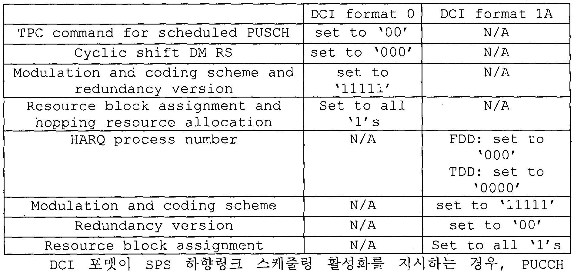
그리고, DCI 포떳에 사용되는 각 필드가 아래 표 4 및 표 5에 따라 셋팅되면 확인이 완료된다. 이러한 확인이 완료되면, 단말은 수신한 DCI 정보를 유효한 SPS 활성화 또는 비활성화 (또는 해제 )임을 인식한다. 반면, 확인이 완료되지 않으면, 단말은 수신한 DCI 포맷에 비매칭 ( non-matching ) CRC가 포함된 것으로 인식한다.
표 4는 SPS 활성화를 지시하는 PDCCH 확인을 위한 필드를 나타낸다.
【표 4】
DCI DCI format DCI format 2 /2A/2B format 0 1 / lA
TPC command for set to N/A N/A scheduled PUSCH " 00 '
Cyclic shi ft DM RS set to N/A N/A
Λ 000 '
Modulation and MSB is N/A N/A coding scheme and set to
redundancy vers ion Ό' HARQ process number N/A FDD: set to FDD: set to λ000' x000' TDD: set to λ0000' TDD: set to
¾0000'
Modulation and N/A MSB is set For the enabled coding scheme to 0' transport block:
MSB is set to λ0'
Redundancy version N/A set to λ00' For the enabled transport block: set to λ00' 표 5는 SPS 비활성화 (또는 해제)를 지시하는 PDCCH 확인을 위한 필드를 나타낸다.
【표 5】
Figure imgf000033_0001
필드를 위한 TPC 명령 값은 상위 계층에 의해 설정된 4개의 PUCCH 자원 값을 나타내는 인텍스로 사용될 수 있다.
PUCCH piggybacking
도 11은 본 발명이 적용될 수 있는 무선 통신 시스템에서 UL-SCH의 전송 채널 프로세싱의 일례를 나타낸다.
3GPP LTE 시스템 (=E-UTRA, Rel. 8)에서는 UL의 경우, 단말기의 파워앰프의 효율적인 활용을 위하여 , 파워 앰프의 성능에 영향을 미치는 PAPR (Peak-to-Average Power Ratio) 특성이나 CM (Cubic Metric) 특성이 좋은 single carrier 전송을 유지하도톡 되어 있다. 즉, 기존 LTE 시스템의 PUSCH 전송의 경우, 전송하고자 하는 데이터를 DFT-precoding을 통해 single carrier 특성을 유지하고, PUCCH 전송의 경우는 single carrier 특성을 가지고 있는 sequence에 정보를 실어 전송함으로써 single carrier 특성을 유지할 수 있다. 그러나 DFT-precoding을 한 데이터를 주파수축으로 비연속적으로 할당하거나 PUSCH와 PUCCH가 동시에 전송하게 되는 경우에는 이러한 single carrier 특성이 깨지게 된다. 따라서, 도 11과 같이 PUCCH 전송과 동일한 subframe에 PUSCH 전송이 있을 경우, s ingle carrier 특성을 유지하기 위해 PUCCH로 전송할 UCI ( uplink control informaticjn )정보를 PUSCH를 통해 데이터와 함께 전송 ( Piggyback )하도톡 되어 있다.
앞서 설명했듯이 기존의 LTE 단말은 PUCCH와 PUSCH가 동시에 전송될 수 없기 때문에 PUSCH71" 전송되는 subframe에서는 Uplink Control Information ( UCI ) ( CQI / PMI , HARQ-ACK, RI등)를 PUSCH 영역에 multiplexing하는 방법을사용한다.
일례로, PUSCH를 전송하도특 allocation 된 subframe에서 Channel Quality Indicator ( CQI ) and/or Precoding Matrix Indicator ( PMI )를 전송해야 할 경우 UL-SCH data와 CQI / PMI를 DFT一 spreading 이전에 multiplexing하여 control 정보와 data를 함께 전송할 수 있다. 이 경우 UL-SCH data는 CQI / PMI resource를 고려하여 rate-matching을 수행하게 된다. 또한 HARQ ACK, RI등의 control 정보는 UL-SCH data를 puncturing 하여 PUSCH 영역에 multiplexing되는 방식이 사용되고 있다.
도 12는 본 발명이 적용될 수 있는 무선 통신 시스템에서 전송 채널 ( transport channel )인 상향링크 공유채널의 신호 처리 과정의 일례를 나타낸다.
이하, 상향링크 공유채널 (이하, JL-SCH'라 한다. )의 신호 처리 과정은 하나 이상의 전송 채널 또는 제어정보 타입에 적용될 수 있다.
도 12를 참조하면, UL-SCH은 전송 시간 구간 ( TTI : transmission time interval )마다 한번씩 데이터를 전송 블톡 ( TB : Transport Block)의 형태로 부호화 유닛 ( conding unit )에 전달된다.
상위 계층으로부터 전달 받은 전송 블록의 비트 "0, , "2,^,"녜- 1에 CRC 패리티 비트 (parity bit) ), , , 3,…, -l를 부착한다 (Si20) . 이때, A는 전송 붙록의 크기이며 , L은 패리티 비트의 개수다. CRC가 부착된 입력 비트는 ^,^,^, ,…,^니과 같다. 이때, B는 CRC를 포함한 전송 블록의 비트 수를 나타낸다.
bQ,bx,b2,b^,...,bB_x 는 TB 크기에 따라 여러 개의 코드 블록 (CB: Code block)으로 분할 (segmentation)되고, 분할된 여러 개의 CB들에 CRC가 부착된다 (S121) . 코드 블톡 분할 및 CRC 부착 후 비트는 crQ,cr ,cr2,cri,...,cr{Kr_x) 과 같다. 여기서 r은 코드 블톡의 번호 (r=0, ,c_
1)이고, _ 은 코드 블톡 r에 따른 비트 수이다. 또한, C는 코드 블록의 총 개수를 나타낸다.
이어 , 채널 부호화 (channel coding)가 수행된다 (S122) . 채널 부호화
d(» d ) dd ) d(>) 、
후의 출력 비트는 O '" ' 2 ' 3'ᅳ'" ^—0과 같다. 이때, 丄는 부호화된 스트림 인텍스이며, 0, 1 또는 2 값을 가질 수 있다. 은 코드 블톡 r을 위한 i번째 부호화된 스트림의 비트 수를 나타낸다. r은 코드 블록 번호 (r=0,...,C-l)이고, C는 코드 블톡의 총 개수를 나타낸다. 각 코드 블록은 각각 터보 코딩에 의하여 부호화될 수 있다.
이어, 레이트 매칭 (Rate Matching)이 수행된다 (S123) . 레이트 매칭을 거친 이후의 비트는 ^。^ ^^^^,…, 과 같다. 이때, r은 코드 블록의 번호이고 (r=0,...,C-l) , C는 코드 블톡의 총 개수를 나타낸다. ¾은 r번째 코드 블록의 레이트 매칭된 비트의 개수를 나타낸다.
이어 , 다시 코드 블록들 간의 결합 (concatenation)이 수행된다 (S124) . 코드 블록의 결합이 수행된 후의 비트는 /ο'/ι'Λ'Λ' '/σ—ι과 같다. 이때, G는 전송을 위한 부호화된 비트의 총 개수를 나타내며, 제어정보가 UL-SCH 전송과 다중화될 때 , 제어정보 전송을 위해 사용되는 비트 수는 포함되지 않는다.
한편 , PUSCH에서 제어정보가 전송될 때 , 제어정보인 CQI/PMI, RI , ACK/NACK은 각각 독립적으로 채널 부호화가 수행된다 (S126, S127, S128) . 각 제어정보의 전송을 위해 각각 서로 다른 부호화된 심볼들이 할당되기 때문에 각각의 제어정보는 서로 다른 코딩 레이트 (coding rate)를 가진다.
TDD (Time Division Duplex)어서 ACK/NACK 피드백 ( feedback) 모드는 Ao^ 계층 설정에 의해 ACK/NACK 번들링 (bundling) 및 ACK/NACK 다중화 (multiplexing) 두 가지 모드가 지원된다. ACK/NACK 번들링을 위해 ACK/NACK 정보 비트는 1비트 또는 2비트로 구성되고, ACK/NACK 다중화를 위해 ACK/NACK 정보 비트는 1비트에서 4비트사이로 구성된다 .
S134 단계에서 코드 블록 간 결합 단계 이후에, UL-SCH 데이터의 부호화된 비트 /θ'/ΐ,Λ'Λ,-,/σ-Ι 와 CQI/PMI의 부호화된 비트 q0,<h,(h,h,---,qNL.QCQ1 -、 의 다증화가 수행된다 (S125) . 데이터와 CQI/PMI의 다증화된 결과는 '^^2, 3" /'_1 과 같다. 이때, ' ( = 0,.-,H'-l )는 ( , O길이를 가지는 컬럼 (column) 백터를 나타낸다. ^G + ^ ^ce/)이고, H^H/(N£' J이다. ^ 은 UL-SCH 전송 블톡이 매핑된 레이어의 개수를 나타내고, H는 전송 블톡이 매핑된 NL 개 전송 레이어에 UL-SCH 데이터와 CQI/PMI 정보를 위해 할당된 부호화된 총 비트의 개수를 나타낸다.
이어, 다중화된 데이터와 CQI/PMI, 별도로 채널 부호화된 RI, ACK/NACK은 채널 인터리빙되어 출력 신호가 생성된다 (S129) .
MIMO (Mul ti - Input Mult i -Output)
MIMO 기술은 지금까지 일반적으로 한 개의 송신안테나와 한 개의 수신안테나를 사용했던 것에서 탈피하여, 다증 송신 (Tx) 안테나와 다중 수신 (Rx) 안테나를 사용한다. 다시 말해서, MIMO 기술은 무선 통신 시스템의 송신단 또는 수신단에서 다중 입출력 안테나를 사용하여 용량 증대 또는 성능 개성을 꾀하기 위한 기술이다. 이하에서는 'ΜΙΜΟ'를 、다중 입출력 안테나 '라 칭하기로 한다.
더 구체작으로, 다중 입출력 안테나 기술은 하나의 완전한 메시지 (total message)를 수신하기 위하여 한 개의 안테나 경로에 의존하지 않으며 , 여러 개의 안테나를 통해 수신한 복수의 데이터 조각을 수집하여 완전한 데이터를 완성시킨다. 결과적으로, 다중 입출력 안테나 기술은 특정 시스템 범위 내에서 데이터 전송율을 증가시킬 수 있으며, 또한 특정 데이터 전송율을 통해 시스템 범위를 증가시킬 수 있다.
차세대 이동통신은 기존 이동통신에 비해 훨씬 높은 데이터 전송률을 요구하므로 효율적인 다중 입출력 안테나 기술이 반드시 필요할 것으로 예상된다. 이와 같은 상황에서 MIMO 통신 기술은 이동통신 단말과 증계기 둥에 폭넓게 사용할 수 있는 차세대 이동통신 기술이며, 데이터 통신 확대 등으로 인해 한계 상황에 따라 다른 이동통신의 전송량 한계를 극복할 수 있는 기술로서 관심을 모으고 있다.
한편, 현재 연구되고 있는 다양한 전송효율 향상 기술 중 다중 입출력 안테나 (MIMO) 기술은 추가적인 주파수 할당이나 전력증가 없이도 통신 용량 및 송수신 성능을 획기적으로 향상시킬 수 있는 방법으로서 현재 가장 큰 주목을 받고 있다.
도 13은 일반적인 다중 입출력 안테나 (MIMO ) 통신 시스템의 구성도이다. 도 13을 참조하면, 송신 안테나의 수를 Ντ개로, 수신 안테나의 수를 NR개로 동시에 늘리게 되면, 송신기나 수신기에서만 다수의 안테나를 사용하게 되는 경우와 달리 안테나 수에 비례하여 이론적인 채널 전송 용량이 증가하므로, 전송 레이트 ( trans fer rate )를 향상시키고, 주파수 효율을 획기적으로 향상시킬 수 있다. 이 경우, 채널 전송 용량의 증가에 따른 전송 레이트는 하나의 안테나를 이용하는 경우의 최대 전송 레이트 ( R0 )에 다음과 같은 레이트 증가율 ( Ri )이 곱해진 만큼으로 이론적으로 증가할 수 있다.
【수학식 1】
Figure imgf000037_0001
즉, 예를 들어, 4개의 송신 안테나와 4개의 수신 안테나를 이용하는 MIMO 통신 시스템에서는 단일 안테나 시스템에 비해 이론상 4배의 전송 레이트를 획득할 수 있다.
이와 같은 다중 입출력 안테나의 기술은 다양한 채널 경로를 통과한 심볼들을 이용하여 전송 신뢰도를 높이는 공간 다이버시티 ( spatial diversity) 방식과, 다수의 송신 안테나를 이용하여 다수의 데이터 심볼을 동시에 송신하여 전송률을 향상시키는 공간 멀티플렉싱 ( spatial multiplexing ) 방식으로 나눌 수 있다. 또한 이러한 두 가지 방식을 적절히 결합하여 각각의 장점올 적절히 얻고자 하는 방식에 대한 연구도 최근 많이 연구되고 있는 분야이다.
각각의 방식에 대해 좀더 구체적으로 살펴보면 다음과 같다.
첫째로, 공간 다이버시티 방식의 경우에는 시공간 블록 부호 계열과, 다이버시티 이득과 부호화 이득을 동시에 이용하는 시공간 트텔리스 (Tre lis ) 부호 계열 방식이 있다. 일반적으로 비트 오류율 개선 성능과 부호 생성 자유도는 트텔리스 부호 방식이 우수하지만, 연산 복잡도는 시공간 블록 부호가 간단하다 . 이와 같은 공간 다이버서티 이득은 송신 안테나 수 ( NT )와 수신 안테나 수 (^½)의 곱 (NT X NR)에 해당되는 양을 얻을 수 있다.
둘째로, 공간 멀티풀렉싱 기법은 각 송신 안테나에서 서로 다른 데이터 열을 송신하는 방법인데, 이때 수신기에서는 송신기로부터 동시에 전송된 데이터 사이에 상호 간섭이 발생하게 된다. 수신기에서는 이 간섭을 적절한 신호처리 기법을 이용하여 제거한 후 수신한다. 여기에 사용되는 잡음 제거 방식은 MLD (maximum likelihood detection ) 수신기 , ZF ( zero- forcing ) 수신기 MMSE (minimum mean square error ) 수신 기, D-BLAST ( Diagonal-Bell Laboratories Layered Space-Time ) , V- BLAST (Vertical-Bel l Laboratories Layered Space-Time ) 등이 있으며 특히 송신단에서 채널 정보를 알 수 있는 경우에는 SVD ( singular value decomposition ) 방식 등을 사용할 수 있다.
셋째로, 공간 다이버시티와 공간 멀티플렉싱의 결합된 기법을 들 수 있다. 공간 다이버시티 이득만을 얻을 경우 다이버시티 차수의 증가에 따른 성능개선 이득이 점차 포화되며, 공간 멀티플렉싱 이득만을 취하면 무선 채널에서 전송 신뢰도가 떨어진다. 이를 해결하면서' 두 가지 이득을 모두 얻는 방식들이 연구되어 왔으며, 이 증 시공간 블톡 부호 ( Double-STTD) , 시공간 BICM ( STBICM) 등의 방식이 있다.
상술한 바와 같은 다중 입출력 안테나 시스템에 있어서의 통신 방법을 보다 구체적인 방법으로 설명하기 위해 이를 수학적으로 모델링하는 경우 다음과 같이 나타낼 수 있다.
먼저, 도 13에 도시된 바와 같이 Ντ개의 송신 안테나와 NR개의 수신 안테나가존재하는 것을 가정한다 .
먼저, 송신 신호에 대해 살펴보면, 이와 같이 Ντ개의 송신 안테나가 있는 경우 최대 전송 가능한 정보는 Ντ개 이므로, 이를 다음과 같은 백터로 나타낼 수 있다.
【수학식 2】
S Sj , 52 , · · · , SN S S '·.
2 한편, 각각의 전송 정보 Sl, s2, sNT에 있어 전송 전력을 달리 할 수 있으며, 이때 각각의 전송 전력을 Ρι, Ρ2, . . . , ΡΝΤ라 하면, 전송 전력이 조정된 전송 정보는 다음과 같은 백터로 나타낼 수 있다.
【수학식 3]
s = [ί, , 52 , · · · , sNj
Figure imgf000039_0001
, P2s2 ,···, PNJ,SNT 또한, S를 전송 전력의 대각 행렬 P로 다음과 같이 나타낼 수 있다.
【수학식 4】
0
S = Ps
0 P, 한편, 전송 전력이 조정된 정보 백터 s는 그 후 가중치 행렬 W가 곱해져 실제 전송되는 NT개의 전송 신호 Xl, x2f ..., 1를 구성한다. 여기서, 가중치 행렬은 전송 채널 상황 등에 따라 전송 정보를 각 안테나에 적절히 분배해 주는 역할을 수행한다. 이와 같은 전송 신호 Xl, X2, xNT를 백터
X를 이용하여 다음과 같이 나타낼 수 있다 .
【수학식 5】
Figure imgf000039_0002
7서, Wij는 i번째 ᄋ _테나와 나타내며, W는 이를 행렬로 나타낸 것이다. 이와 같은 행렬 W를 가중치 행렬 ( Weight Matrix ) 또는 프리코딩 행렬 ( Precoding Matrix )라 부른다. 한편 , 상술한 바와 같은 전송 신호 ( X )는 공간 다이버시티를 사용하는 경우와공간 멀티플랙싱을사용하는 경우로 나누어 생각해 볼 수 있다.
공간 멀티플랙싱을 사용하는 경우는 서로 다른 신호를 다증화하여 보내게 되므로, 정보 백터 s의 원소들이 모두 다른 값을 가지게 되는 반면, 공간 다이버시티를 사용하게 되면 같은 신호를 여러 채널 경로를 통하여 보내게 되므로 정보 백터 s의 원소들이 모두 같은 값을 갖게 된다.
물론, 공간 멀티플랙싱과 공간 다이버시티를 혼합하는 방법도 고려 가능하다. 즉, 예를 들어 3 개의 송신 안테나를 통하여 같은 신호를 공간 다이버시티를 이용하여 전송하고, 나머지는 각각 다른 신호를 공간 멀티플택싱하여 보내는 경우도 고려할 수 있다.
다음으로, 수신신호는 NR개의 수신 안테나가 있는 경우, 각 안테나의 수신신호 yi , y2 , yNR을 백터 y로 다음과 같이 나타내기로 한다.
Figure imgf000040_0001
한편, 다중 입출력 안테나 통신 시스템에 있어서의 채널을 모델링하는 경우, 각각의 채널은 송수신 안테나 인덱스에 따라 구분할 수 있으며, 송신 안테나 j로부터 수신 안테나 i를 거치는 채널을 로 표시하기로 한다. 여기서, hij의 인텍스의 순서가 수신 안테나 인텍스가 먼저, 송신안테나의 인텍스가 나중임에 유의한다.
이러한 채널은 여러 개를 한데 묶어서 백터 및 행렬 형태로도 표시 가능하다. 백터 표시의 예를 들어 설명하면 다음과 같다.
도 14는 다수의 송신 안테나에서 하나의 수신 안테나로의 채널을 나타낸 도이다.
도 14에 도시된 바와 같이 총 Ντ개의 송신 안테나로부터 수신안테나 i로 도착하는 채널은 다음과 같이 표현 가능하다.
【수학식 7】 또한, 상기 수학식 7과 같은 행렬 표현을 통해 Ντ개의 송신 안테나로부터 NR개의 수신 안테나를 거치는 채널을 모두 나타내는 경우 다음과 같이 나타낼 수 있다.
【수학식 8】
Figure imgf000041_0001
한편, 실제 채널은 위와 같은 채널 행렬 H를 거친 후에 백색 잡음 (AWGN: Additive White Gaussian Noise)가 더해지게 되므로, NR개의 수신 안테나 각각에 더해지는 백색 잡음 ηι, n2, nNR을 백터로 표현하면 다음과 같다.
【수학식 9】
Figure imgf000041_0002
상술한 바와 같은 전송 신호, 수신 신호, 채널, 및 백색 잡음의 모델링을 통해 다중 입출력 안테나 통신 시스템에서의 각각은 다음과 같은 관계를 통해 나타낼 수 있다.
【수학식 10]
= Hx + n
Figure imgf000041_0003
한편, 채널의 상태를 나타내는 채널 행렬 H의 행과 열의 수는 송수신 안테나 수에 의해서 결정된다. 채널 행렬 H는 앞서 살펴본 바와 같이 행의 수는 수신 안테나의 수 1½과 같아지고, 열의 수는 송신 안테나의 수 ¾와 같아 지게 된다. 즉, 채널 행렬 H는 NRXNR 행렬이 된다.
일반적으로, 행렬의 탱크 (rank)는 서로 독립인 (independent) 행 또는 열의 개수 중에서 최소 개수로 정의된다. 따라서, 행렬의 탱크는 행 또는 열의 개수 ^다 클 수 없게 된다. 수식적으로 예를 들면, 채널 행렬 H의 탱크 (rank (H) )는 다음과 같이 제한된다.
【수학식 11]
rank (H)< min (NT, NR )
또한, 행렬을 고유치 분해 (Eigen value decomposition)를 하였을 때, 랭크는 고유치 (eigen value)들 중에서 0이 아닌 고유치들의 개수로 정의할 수 있다. 비슷한 방법으로, 랭크를 SVD (singular value decomposition) 했을 때 0이 아닌 특이값 (singular value)들의 개수로 정의할 수 있다. 따라서, 채널 행렬에서 탱크의 물리적인 의미는 주어진 채널에서 서로 다른 정보를 보낼 수 있는 최대 수라고 할 수 있다.
본 명세서에 있어, MIMO 전송에 대한 '탱크 (Rank) '는 특정 시점 및 특정 주파수 자원에서 독립적으로 신호를 전송할 수 있는 경로의 수를 나타내며, '레이어 (layer)의 개수'는 각 경로를 통해 전송되는 신호 스트림의 개수를 나타낸다. 일반적으로 송신단은 신호 전송에 이용되는 랭크 수에 대웅하는 개수의 레이어를 전송하기 때문에 특별한 언급이 없는 한 탱크는 레이어 개수와 동일한 의미를 가진다. 참조신호 (RS: Reference Signal)
무선 통신 시스템에서 데이터는 무선 채널을 통해 전송되기 때문에, 신호는 전송 중에 왜곡될 수 있다. 수신단에서 왜곡된 신호를 정확하게 수신하기 위하여, 수신된 신호의 왜곡은 채널 정보를 이용하여 보정되어야 한다. 채널 정보를 검출하기 위하여 송신측과 수신측 모두 알고 있는 신호 전송 방법과 신호가 채널을 통해 전송될 때 왜곡된 정도를 이용하여 채널 정보를 검출하는 방법을 주로 이용한다. 상술한신호를 파일럿 신호 또는 참조 신호 (RS)라고 한다.
다중 입출력 안테나를 이용하여 데이터를 송수신할 때, 신호를 정확하게 수신하기 위하여 송신 안테나와 수신 안테나 간의 채널 상태가 검출되어야 한다. 따라서 각송신 안테나는 개별적인 참조 신호를 가져야 한다.
하향 참조 신호는 하나의 샐 내 모든 단말이 공유하는 공통 참조 신호 (CRS: common RS)와 특정 단말만을 위한 전용 참조 신호 (DRS: dedicated RS)가 있다. 이와 같은 참조 신호들을 이용하여 복조 (demodulation)와 채널 측정 (channel measurement) 위한 정보를 제공할 수 있다.
수신 측 (즉, 단말)은 CRS로부터 채널 상태를 측정하고, CQI (Channel Quality Indicator) , ΡΜΙ (Precoding Matrix Index) 및 /또는 RI (Rank Indicator)와 같은 채널 품질과 관련된 지시자를 송신 측 (즉, 기지국)으로 피드백한다. CRS는 셀 특정 기준신호 (cell-specific RS)라고도 한다. 반면, 채널 상태 정보 (CSI: Channel State Information)의 피드백과 관련된 참조 신호를 CSI-RS라고 정의할 수 있다.
DRS는 PDSCH 상의 데이터 복조가 필요한 경우 자원 요소들을 통해 전송될 수 있다. 단말은 상위 계층을 통하여 DRS의 존재 여부를 수신할 수 있으며, 상웅하는 PDSCH가 매핑되었을 때만 유효하다. DRS를 단말 특정 참조 신호 (UE- specific RS) 또는 복조 참조 신호 (DMRS: Demodulation RS)라고 할 수 있다.
도 15는 본 발명이 적용될 수 있는 무선 통신 시스템에서 하향링크 자원 블록 쌍에 매핑된 참조 신호 패턴을 예시한다.
도 15를 참조하면, 참조 신호가 매핑되는 단위로 하향링크 자원 불록 쌍은 시간 영역에서 하나의 서브 프레임 X 주파수 영역에서 12개의 부 반송파로 나타낼 수 있다. 즉, 시간 축 (X축) 상에서 하나의 자원 블록 쌍은 일반 순환 전치 (normal CP: normal Cyclic Prefix) 인 경우 14개의 OFDM 심볼의 길이를 가지고 (도 15의 (a)의 경우) , 확장 순환 전치 (extended CP: extended Cyclic Prefix)인 경우 12개의 OFDM 심볼의 길이를 가진다 (도 15의 (b)의 경우) . 자원 블록 격자에서 '2' 및 '3'으로 기재된 자원 요소들 (REs)은 각각 안테나 포트 인텍스 '0', '1', '2' 및 '3'의 CRS의 위치를 의미하며 , 'D'로 기재된 자원 요소들은 DRS와위치를 의미한다. 이하 CRS에 대하여 좀 더 상세하게 기술하면, CRS는 물리적 안테나의 채널을 추정하기 위해 사용되고, 셀 내에 위치한 모든 단말에 공통적으로 수신될 수 있는 참조 신호로써 전체 주파수 대역에 분포된다. 또한, CRS는 채널 품질 정보 (CSI) 및 데이터 복조를 위해 이용될 수 있다.
CRS는 전송 측 (기지국)에서의 안테나 배열에 따라 다양한 포맷으로 정의된다 . 3GPP LTE 시스템 (예를 들어 , 릴리즈 -8)에서는 다양한 안테나 배열을 지원하고, 하향링크 신호 송신 측은 3개의 단일의 송신 안테나, 2개의 송신 안테나 및 4개의 송신 안테나와 같이 3 종류의 안테나 배열을 가진다. 기지국이 단일의 송신 안테나를 사용하는 경우, 단일 안테나 포트를 위한 참조 신호가 배열된다. 기지국이 2개의 송신 안테나를 사용하는 경우, 2개의 송신 안테나 포트를 위한 참조 신호는 시분할 다증화 (TDM: Time Division Multiplexing) 및 /또는 주파수 분할 다증화 (FDM Frequency Division Multiplexing) 방식을 이용하여 배열된다. 즉, 2개의 안테나 포트를 위한 참조 신호는 각각이 구별되기 위해 서로 다른 시간 자원 및 /또는 서로 다른 주파수 자원이 할당된다.
게다가, 기지국이 4개의 송신 안테나를 사용하는 경우, 4개의 송신 안테나 포트를 위한 참조 신호는 TDM 및 /또는 FDM 방식을 이용하여 배열된다. 하향링크 신호의 수신 측 (단말)에 의하여 측정된 채널 정보는 단일의 송신 안테나 전송, 송신 다이버시티, 폐쇄 루프 공간 다중화 (closed-loop spatial multiplexing) , 개방 루프 공간 다중화 (open— ljop spatial multiplexing) 또는 다증 入 1"용자一다중 입출력 안테나 (Multi-User MIM0)와 같은 전송 방식을 이용하여 전송된 데이터를 복조하기 위하여 사용될 수 있다. 다증 입출력 안테나가 지원되는 경우 참조 신호가 특정의 안테나 포트로부터 전송될 때, 상기 참조 신호는 참조 신호의 패턴에 따라 특정된 자원 요소들의 위치에 전송되며, 다른 안테나 포트를 위해 특정된 자원 요소들의 위치에 전송되지 않는다. 즉, 서로 다른 안테나사이의 참조 신호는 서로 겹치지 않는다.
자원 블록에 CRS를 맵핑하는 규칙은 다음과 같이 정의된다.
【수학식 12】
k = 6m + (v + vshift )mod6
,_ ί ,¾-3 if e{0,l}
Figure imgf000044_0001
Figure imgf000045_0001
vshift = ' mod6
수학식 12에서, k 및 1 은 각각 부반송파 인텍스 및 심볼 인텍스를 나타내고, p 는 안테나 포트를 나타낸다 . 은 하나의 하향링크 슬롯에서의
OFDM 심볼의 수를 나타내고, 은 하향링크에 할당된 무선 자원의 수를 나타낸다. ns 는 슬롯 인텍스를 나타내고, D 은 셀 I D를 나타낸다. mod 는 모들로 (modulo ) 연산을 나타낸다. 참조 신호의 위치는 주파수 영역에서 vshift 값에 따라 달라진다. Vsh'ft 는 샐 I D에 종속되므로, 참조 신호의 위치는 셀에 따라 다양한주파수 편이 ( frequency shift ) 값을 가진다.
보다 구체적으로, CRS를 통해 채널 추정 성능을 향상시키기 위해 CRS의 위치는 셀에 따라 주파수 영역에서 편이될 수 있다. 예를 들어 , 참조 신호가 3개의 부 반송파의 간격으로 위치하는 경우, 하나의 셀에서의 참조 신호들은 3k 번째 부반송파에 할당되고, 다른 샐에서의 참조 신호는 3 k+l 번째 부반송파에 할당된다. 하나의 안테나 포트의 관점에서 참조 신호들은 주파수 영역에서 6개의 자원 요소 간격으로 배열되고, 또 다른 안테나 포트에 할당된 참조 신호와는 3개의 자원 요소 간격으로 분리된다 .
시간 영역에서 참조 신호는 각 슬롯의 심볼 인덱스 0 에서부터 시작하여 동일 간격 ( constant interval )으로 배열된다. 시간 간격은 순환 전치 길이에 따라 다르게 정의된다. 일반 순환 전치의 경우 참조 신호는 슬롯의 심볼 인텍스 0 과 4에 위치하고, 확장 순환 전치의 경우 참조 신호는 슬롯의 심볼 인덱스 0 과 3에 위치한다. 2개의 안테나 포트 중 최대값을 가지는 안테나 포트를 위한 참조 신호는 하나의 OFDM 심볼 내에 정의된다 . 따라서 , 4개의 송신 안테나 전송의 경우, 참조 신호 안테나 포트 0 과 1을 위한 참조 신호는 슬롯의 심볼 인텍스 0 과 4 (확장 순환 전치의 경우 심볼 인덱스 ◦ 과 3 )에 위치하고, 안테나 포트 2 와 3을 위한 참조 신호는 슬롯의 심볼 인텍스 1에 위치한다. 안테나 포트 2 와 3을 위한 참조 신호의 주파수 영역에서의 위치는 2번째 슬롯에서 서로 맞바꿔진다 .
이하 DRS에 대하여 좀 더 상세하게 기술하면 , DRS는 데이터를 복조하기 위하여 사용된다. 다중 입출력 안쩨나 전송에서 특정의 단말을 위해 사용되는 선행 부호화 ( preceding ) 가중치는 단말이 참조 신호를 수신하였을 때 각 송신 안테나에서 전송된 전송 채널과 결합되어 상웅하는 채널올 추정하기 위하여 변경 없이 사용된다.
3GPP LTE 시스템 (예를 들어 , 릴리즈 -8 )은 최대로 4개의 전송 안테나를 지원하고, 탱크 1 빔포밍 ( beamforming )을 위한 DRS가 정의된다. 탱크 1 범포밍을 위한 DRS는 또한 안테나 포트 인덱스 5 를 위한 참조 신호를 나타낸다. 자원 블록에 DRS를 맵핑하는 규칙은 다음과 같이 정의된다. 수학식 13은 일반 순환 전치인 경우를 나타내고, 수학식 14는 확장 순환 전치인 경우를 나타낸다.
【수학식 13 ]
A: = (A:') mod N^ + Ns -"PRB
Figure imgf000046_0001
3 /' = 0
6 = 1
2 /' = 2
' = 3
Figure imgf000046_0002
= C mod 3
【수학식 14 ]
Figure imgf000047_0001
= A mod 3
상기 수학식 12내지 수학식 14에서, k 및 p는 각각 부반송파 인텍스 및 안테나 포트를 나타낸다. ^RB , ns , 는 각각 하향링크에 할당된 RB의 수, 슬롯 인덱스의 수, 샐 ID의 수를 나타낸다. RS의 위치는 주파수 도메인 관점에서 vshift값에 따라 달라진다.
수학식 13 및 14에서, k 및 1 은 각각 부반송파 인텍스 및 심볼 인덱스를 나타내고, p 는 안테나 포트를 나타낸다. 은 주파수 영역에서 자원 블톡 크기를 나타내고, 부반송파의 수로써 표현된다. "PRB 은 물리 자원 블록의 수를
ArPDSCH
나타낸다. B 은 PDSCH 전송을 위한 자원 블록의 주파수 대역을 나타낸다. ns 는 슬롯 인텍스를 나타내고, 는 셀 I D를 나타낸다. mod 는 모들로 (modulo ) 연산을 나타낸다. 참조 신호의 위치는 주파수 영역에서 Vshift 값에 따라 달라진다. ^^는 셀 ID에 종속되므로, 참조 신호의 위치는 셀에 따라 다양한 주파수 편이 ( frequency shift ) 값을 가진다. 사운딩 참조신호 ( SRS : Sounding Reference Signal )
SRS는 주로 상향링크의 주파수-선택적 스케줄링을 수행하기 위하여 채널 품질 측정에 사용되며, 상향링크 데이터 및 /또는 제어 정보의 전송과 관련되지 않는다. 그러나, 이에 한정되지 않으며 SRS는 전력 제어의 향상 또는 최근에 스케줄되어 있지 않은 단말들의 다양한 스타트-업 ( start-up ) 기능을 지원하기 위한 다양한 다른 목적들을 위해 사용될 수 있다. 스타트-업 기능의 일례로, 초기의 변조 및 부호화 방식 (MCS : Modulation and Coding Scheme ) , 데이터 전송을 위한 초기의 전력 제어, 타이밍 전진 (timing advance) 및 주파수 반-선택적 (semi— selective) 스케줄링이 포함될 수 있다. 이때, 주파수 반-선택적 스케줄링은 서브 프레임의 처음의 슬롯에 선택적으로 주파수 자원을 할당하고, 두번째 슬롯에서는 다른 주파수로 의사 랜덤 (pseudo- randomly)하게 도약하여 주파수 자원을 할당하는 스케줄링을 말한다.
또한, SRS는 상향링크와 하향링크 간에 무선 채널이 상호적 (reciprocal)인 가정하에 하향링크 채널 품질을 측정하기 위하여 사용될 수 있다. 이러한 가정은 상향링크와 하향링크가 동일한 주파수 스펙트럼을 공유하고, 시간 영역에서는 분리된 시분할 듀플레스 (TDD: Time Division Duplex) 시스템에서 특히 유효하다
셀 내에서 어떠한 단말에 의하여 전송되는 SRS의 서브 프레임들은 샐 -특정 방송 신호에 의하여 나타낼 수 있다. 4비트 셀 -특정
' srsSubf rameConf iguration ' 파라미터는 SRS가 각 무선 프레임을 통해 전송될 수 있는 15가지의 가능한 서브 프레임의 배열을 나타낸다. 이러한 배열들에 의하여 , 운용 시나리오 (deployment scenario)에 따라 SRS 오버헤드 (overhead)의 조정에 대한유동성을 제공하게 된다.
이 중 16번째 배열은 셀 내에서 완전하게 SRS의 스위치를 오프하며, 이는 주로 고속 단말들을 서빙하는 서빙 셀에 적합하다.
도 16은 본 발명이 적용될 수 있는 무선 통신 시스템에서 사운딩 참조 신호 심블을 포함한 상향링크 서브 프레임을 예시한다 .
도 16을 참조하면, SRS는 배열된 서브 프레임 상에서 항상 마지막 SC- FDMA 심볼을 통해 전송된다. 따라서, SRS와 DMRS는 다른 SC-FDMA 심볼에 위치하게 된다 .
PUSCH 데이터 전송은 SRS 전송을 위한 특정의 SC-FDMA 심볼에서는 허용되지 않으며, 결과적으로 사운딩 (sounding) 오버헤드가 가장 높은 경우 즉 모든 서브 프레임에 SRS 심블이 포함되는 경우라도 사운딩 오버헤드는 약 7 를 초과하지 않는다.
각 SRS 심볼은 주어진 시간 단위와 주파수 대역에 관한 기본 시퀀스 (랜덤 시뭔스 또는 Zadoff-Ch(ZC)에 기초한 시뭔스 세트)에 의하여 생성되고, 동일 셀 내의 모든 단말들은 동일한 기본 시퀀스를 사용한다. 이때, 동일한 주파수 대역과 동일한 시간에서 동일 셀 내의 복수의 단말로부터의 SRS 전송은 기본 시뭔스의 서로 다른 순환 이동 (cyclic shift)에 의해 직교 (orthogonal)되어 서로 구별된다.
각각의 셀 마다 서로 다른 기본 시퀀스가 할당되는 것에 의하여 서로 다른 셀로부터의 SRS 시퀀스가 구별될 수 있으나, 서로 다른 기본 시퀀스 간에 직교성은 보장되지 않는다,
COMP (Coordinated Multi-Point Transmission and Reception)
LTE-advanced의 요구에 발맞춰, 시스템의 성능 향상을 위하여 CoMP 전송이 제안되었다. CoMP는 co-MIMO, collaborative MIMO, network MIMO 등으로도 불린다. CoMP는 셀 경계에 위치한 단말의 성능을 향상시키고, 평균 셀 (색터 )의 효율 (throughput)을 향상시킬 것으로 예상된다.
일반적으로, 셀 간 간섭 (Inter-Cell Interference)은 주파수 재사용 지수가 1 인 다중-셀 환경에서 셀 경계에 위치한 단말의 성능 및 평균 샐 (섹터 ) 효율을 떨어뜨린다. 셀 간 간섭을 완화시키기 위해, 간섭 제한적인 (interference-limited) 환경에서 셀 경계에 위치한 단말이 적정한 성능 효율을 가지도록 LTE 시스템에서는 부분 주파수 재사용 (FFR: Fractional Frequency Reuse)과 같은 단순한 수동적인 방법이 적용되었다. 그러나, 각 셀 당 주파수 자원의 사용을 감소시키는 대신, 단말이 수신해야 하는 신호 (desired signal)로써 샐 간 간섭을 재 사용하거나 샐 간 간섭을 완화시키는 방법이 보다 이익이 된다. 상술한 목적을 달성하기 위하여 CoMP 전송 방식이 적용될 수 있다. '
하향링크에 적용될 수 있는 CoMP 식은 JP( Joint Processing) HJ"식과 CS/CB (Coordinated Scheduling/Beamforming) 방식으로 분류할 수 있다.
JP 방식에서 , 데이터는 CoMP 단위의 각 포인트 (기지국)에서 사용될 수 있다 . CoMP 단위는 CoMP 방식에서 이용되는 기지국들의 집합을 의미한다 . JP 방식은 다시 연합 전송 (joint transmission) 방식과 동적 셀 선택 (dynamic cell selection) 방식으로 분류할 수 있다.
연합 전송 방식은 CoMP 단위에서 전체 또는 일부분인 복수의 포인트로부터 PDSCH를 통해 신호가 동시에 전송되는 방식을 의미한다. 즉, 단일의 단말에 전송되는 데이터는 복수의 전송 포인트로부터 동시에 전송될 수 있다. 이와 같은 연합 전송 방식을 통해 가간섭적 ( coherently) 내지 비간섭적 ( non- coherently)이든 무관하게 단말에 전송되는 신호의 품질올 높일 수 있으며 , 또 다른 단말과의 간섭을 적극적으로 제거할수 있다.
동적 샐 선택 방식은 coMP 단위에서 단일의 포인트로부터 PDSCH를 통해 신호가 전송되는 방식을 의미한다. 즉, 특정 시간에 단일의 단말에 전송되는 데이터는 단일의 포인트로부터 전송되고, CoMP 단위 내 다른 포인트에서는 상기 단말로 데이터를 전송하지 않는다. 단말로 데이터를 전송하는 포인트는 동 으로 선택될 수 있다.
CS /CB 방식에 따르면, CoMP 단위는 단일의 단말로의 데이터 전송을 위하여 협력하여 빔포밍을 수행하게 된다. 즉, 서빙 셀에서만 단말로 데이터를 전송하지만, 사용자 스케줄링 /범포밍은 CoMP 단위 내의 복수의 셀 간의 협력을 통해 결정될 수 있다.
상향링크의 경우, CoMP 수신은 지리적으로 분리된 복수의 포인트 간의 협력에 의하여 전송된 신호를 수신하는 것을 의미한다. 상향링크에 적용될 수 있는 CoMP 방식은 JR ( Joint Reception ) 방식과 CS /CB ( Coordinated Scheduling/Beamforming ) 방식으로 분류할 수 있다.
JR 방식은 CoMP 단위에서 전체 또는 일부분인 복수의 포인트가 PDSCH를 통해 전송된 신호를 수신하는 방식을 의미한다. CS/CB 방식은 단일의 포인트에서만 PDSCH를 통해 전송된 신호를 수신하게 되나, 사용자 스케줄링 /범포밍은 CoMP 단위 내의 복수의 셀 간의 협력을 통해 결정될 수 있다. 릴레이 노드 (R ; Relay Node)
릴레이 노드는 기지국과 단말 간의 송수신되는 데이터를 두 개의 다른 링크 (백홀 링크 및 액세스 링크)를 통해 전달한다. 기지국은 도너 ( donor ) 샐을 포함할 수 있다. 릴레이 노드는 도너 샐올 통해 무선으로 무선 액세스 네트워크에 연결된다.
한편, 릴레이 노드의 대역 (또는 스펙트럼) 사용과 관련하여, 백홀 링크가 액세스 링크와 동일한 주파수 대역에서 동작하는 경우를 '인 -밴드 ( in- band) '라고 하고, 백홀 링크와 액세스 링크가상이한 주파수 대역에서 동작하는 경우를 '아웃 -밴드 ( out-band) '라고 한다. 인 -밴드 및 아웃 -밴드 경우 모두 기존의 LTE 시스템 (예를 들어 , 릴리즈 -8 )에 따라 동작하는 단말 (이하, 레거시 ( legacy) 단말이라 한다. )이 도너 샐에 접속할수 있어야 한다.
단말에서 릴레이 노드를 인식하는지 여부에 따라 릴레이 노드는 트랜스패런트 ( transparent ) 릴레이 노드 또는 넌-트랜스패런트 ( non- transparent ) 릴레이 노드로 분류될 수 있다. 트랜스패런트는 단말이 릴레이 노드를 통하여 네트워크와 통신하는지 여부를 인지하지 못하는 경우를 의미하고, 년-트랜스패런트는 단말이 릴레이 노드를 통하여 네트워크와 통신하는지 여부를 인지하는 경우를 의미한다.
릴레이 노드의 제어와 관련하여, 도너 셀의 일부로 구성되는 릴레이 노드 또는 스스로 셀을 제어하는 릴레이 노드로 구분될 수 있다.
도너 셀의 일부로 구성되는 릴레이 노드는 릴레이 노드 식별자 ( relay ID)를 가질 수는 있지만,' 릴레이 노드 자신의 셀 식별자 ( cell identity )를 가지지 않는다.
도너 샐이 속하는 기지국에 의하여 RRM (Radio Resource Management )의 적어도 일부가 제어되면, RRM의 나머지 부분들이 릴레이 노드에 위치하더라도 도너 셀의 일부로서 구성되는 릴레이 노드라 한다. 바람직하게, 이러한 릴레이 노드는 레거시 단말을 지원할 수 있다. 예를 들어, 스마트 리피터 ( Smart repeaters ) , 디코드 -앤-포워드 릴레이 노드 (decode- and-forward relays ) , L2 (제 2계층) 릴레이 노드들의 다양한 종류들 및 타입 -2 릴레이 노드가 이러한 릴레이 노드에 해당한다.
스스로 셀을 제어하는 릴레이 노드의 경우에 릴레이 노드는 하나 또는 복수 개의 샐들을 제어하고, 릴레이 노드에 의해 제어되는 셀들 각각에 고유의 물리계층 셀 식별자가 제공된다. 또한, 릴레이 노드에 의해 제어되는 샐들 각각은 동일한 RRM 메커니즘을 이용할 수 있다. 단말 관점에서는 릴레이 노드에 의하여 제어되는 셀에 액세스하는 것과 일반 기지국에 의해 제어되는 샐에 액세스하는 것에 차이점이 없다. 이러한 릴레이 노드에 의해 제어되는 셀은 레거시 단말을 지원할 수 있다. 예를 들어, 셀프-백홀링 ( Self-backhauling ) 릴레이 노드, L3 (제 3계층) 릴레이 노드, 타입 -1 릴레이 노드 및 타입 -la 릴레이 노드가 이러한 릴레이 노드에 해당한다. 타입 - 1 릴레이 노드는 인 -밴드 릴레이 노드로서 복수개의 셀들을 제어하고 이들 복수개의 셀들의 각각은 단말 입장에서 도너 셀과 구별되는 별개의 셀로 보인다. 또한, 복수개의 샐들은 각자의 물리 샐 I D (이는 LTE 릴리즈 -8에서 정의됨 )를 가지고, 릴레이 노드는 자신의 동기화 채널, 참조신호 등을 전송할 수 있다. 단일-셀 동작의 경우에, 단말은 릴레이 노드로부터 직접 스케줄링 정보 및 HARQ 피드백을 수신하고 릴레이 노드로 자신의 제어 채널 (스케줄링 요청 ( SR ) , CQI , ACK/NACK 등)을 전송할 수 있다. 또한, 레거시 단말 ( LTE 릴리즈 -8 시스템에 따라 동작하는 단말)들에게 타입 - 1 릴레이 노드는 레거시 기지국 ( LTE 릴리즈 - 8 시스템에 따라 동작하는 기지국)으로 보인다. 즉, 역방향 호환성 (backward compatibi l ity )을 7진다. 한편, LTE-A 시스템에 따라 동작하는 단말들에게는, 타입 - 1 릴레이 노드는 레거시 기지국과 다른 기지국으로 보여, 성능 향상을 제공할수 있다.
타입 - la 릴레이 노드는 아웃-밴드로 동작하는 것 외에 전술한 타입 - 1 릴레이 노드와 동일한 특징들을 가진다. 타입 - la 릴레이 노드의 동작은 L1 (제 1계층) 동작에 대한 영향이 최소화 또는 없도록 구성될 수 있다.
타입— 2 릴레이 노드는 인 -밴드 릴레이 노드로서, 별도의 물리 셀 I D를 가지지 않으며, 이에 따라 새로운 셀을 형성하지 않는다. 타입— 2 릴레이 노드는 레거시 단말에 대해 트랜스패런트하고, 레거시 단말은 타입 -2 릴레이 노드의 존재를 인지하지 못한다. 타입 -2 릴레이 노드는 PDSCH를 전송할 수 있지만, 적어도 CRS 및 PDCCH는 전송하지 않는다.
한편 , 릴레이 노드가 인-밴드로 동작하도록 하기 위하여 , 시간-주파수 공간에서의 일부 자원이 백홀 링크를 위해 예비되어야 하고 이 자원은 액세스 링크를 위해서 사용되지 않도록 설정할 수 있다. 이를 자원 분할 ( resource partitioning )이라 한다.
릴레이 노드에서의 자원 분할에 있어서의 일반적인 원리는 다음과 같이 설명할 수 있다. 백홀 하향링크 및 액세스 하향링크가 하나의 반송파 주파수 상에서 시간분할다증화 ( TDM) 방식으로 다중화될 수 있다 (즉, 특정 시간에서 백홀 하향링크 또는 액세스 하향링크 중 하나만이 활성화된다) . 유사하게, 백홀 상향링크 및 액세스. 상향링크는 하나의 반송파 주파수 상에서 TDM 방식으로 다중화될 수 있다 (즉, 특정 시간에서 백홀 상향링크 또는 액세스 상향링크 중 하나만이 활성화된다) .
FDD 에서의 백홀 링크 다중화는, 백홀 하향링크 전송은 하향링크 주파수 대역에서 수행되고, 백홀 상향링크 전송은 상향링크 주파수 대역에서 수행될 수 있다. TDD 에서의 백홀 링크 다중화는, 백홀 하향링크 전송은 기지국과 릴레이 노드의 하향링크 서브프레임에서 수행되고, 백홀 상향링크 전송은 기지국과 릴레이 노드의 상향링크 서브프레임에서 수행될 수 있다.
인 -밴드 릴레이 노드의 경우에, 예를 들어, 동일한 주파수 대역에서 기지국으로부터의 백홀 하향링크 수신과 단말로의 액세스 하향링크 전송이 동시에 이루어지면, 릴레이 노드의 송신단으로부터 전송되는 신호에 의하여 릴레이 노드의 수신단에서 신호 간섭이 발생할 수 있다. 즉, 릴레이 노드의 RF 전단 ( front-end )에서 신호 간섭 또는 RF 재밍 ( j amming )이 발생할 수 있다. 유사하게, 동일한 주파수 대역에서 기지국으로의 백홀 상향링크 전송과 단말로부터의 액세스 상향링크 수신이 동시에 이루어지는 경우도 신호 간섭이 발생할 수 있다.
따라서, 릴레이 노드에서 동일한 주파수 대역에서의 동시에 신호를 송수신하기 위해서 , 수신 신호와 송신 신호간에 층분한 분리 (예를 들어 , 송신 안테나와 수신 안테나를 지상 /지하에 설치하는 것과 같이 지리적으로 충분히 이격시켜 설치함)가 제공되지 않으면 구현하기 어렵다.
이와 같은 신호 간섭의 문제를 해결하는 한 가지 방안은, 릴레이 노드가 도너 셀로부터 신호를 수신하는 동안에 단말로 신호를 전송하지 않도록 동작하게 하는 것이다. 즉, 릴레이 노드로부터 단말로의 전송에 갭 ( gap )을 생성하고, 이 갭 동안에는 단말 (레거시 단말 포함)이 릴레이 노드로부터의 어떠한 전송도 기대하지 않도록 설정할 수 있다. 이러한 갭은 MBSFN (Multicast Broadcast Single Frequency Network) 서브프레임을 구성함으로써 설정할 수 있다. 도 17은 본 발명이 적용될 수 있는 무선 통신 시스템에서 릴레이 노드 자원 분할을 예시한다 .
도 17에서, 첫번째 서브프레임은 일반 서브프레임으로서 릴레이 노드로부터 단말로 하향링크 (즉, 액세스 하향링크) 제어신호 및 데이터가 전송되고, 두번째 서브프레임은 MBSFN 서브프레임으로서 하향링크 서브프레임의 제어 영역에서는 릴레이 노드로부터 단말로 제어 신호가 전송되지만 하향링크 서브프레임의 나머지 영역에서는 릴레이 노드로부터 단말로 아무런 전송이 수행되지 않는다. 여기서, 레거시 단말의 경우에는 모든 하향링크 서브프레임에서 PDCCH의 전송을 기대하게 되므로 (다시 말하자면, 릴레이 노드는 자신의 영역 내의 레거시 단말들이 매 서브프레임에서 PDCCH를 수신하여 측정 기능을 수행하도톡 지원할 필요가 있으므로) , 레거시 단말의 올바른 동작을 위해서는 모든 하향링크 서브프레임에서 PDCCH를 전송할 필요가 있다. 따라서, 기지국으로부터 릴레이 노드로의 하향링크 (즉, 백홀 하향링크) 전송을 위해 설정된 서브프레임 (두번째 서브프레임 )상에서도, 서브프레임의 처음 N ( N=l , 2 또는 3 ) 개의 OFDM 심볼구간에서 릴레이 노드는 백홀 하향링크를 수신하는 것이 아니라 액세스 하향링크 전송을 해야 할 필요가 있다. 이에 대하여, 두번째 서브프레임의 제어 영역에서 PDCCH가 릴레이 노드로부터 단말로 전송되므로 릴레이 노드에서 서빙하는 레거시 단말에 대한 역방향 호환성이 제공될 수 있다. 제 2 서브프레임의 나머지 영역에서는 릴레이 노드로부터 단말로 아무런 전송이 수행되지 않는 동안에 릴레이 노드는 기지국으로부터의 전송을 수신할 수 있다. 따라서, 이러한 자원 분할 방식을 통해서, 인 -밴드 릴레이 노드에서 액세스 하향링크 전송과 백홀 하향링크 수신이 동시에 수행되지 않도특 할 수 있다.
MBSFN 서브프레임을 이용하는 두번째 서브프레임에 대하여 구체적으로 설명한다. 두번째 서브프레임의 제어 영역은 릴레이 노드 비 -청취 ( non- hearing ) 구간이라고 할 수 있다. 릴레이 노드 비 -청취 구간은 릴레이 노드가 백홀 하향링크 신호를 수신하지 않고 액세스 하향링크 신호를 전송하는 구간을 의미한다. 이 구간은 전술한 바와 같이 1 , 2 또는 3 OFDM 길이로 설정될 수 있다. 릴레이 노드 비 -청취 구간에서 릴레이 노드는 단말로의 액세스 하향링크 전송을 수행하고 나머지 영역에서는 기지국으로부터 백홀 하향링크를 수신할 수 있다. 이 때, 릴레이 노드는 동일한 주파수 대역에서 동시에 송수신을 수행할 수 없으므로, 릴레이 노드가 송신 모드에서 수신 모드로 전환하는 데에 사간이 소요된다. 따라서, 백홀 하향링크 수신 영역의 처음 일부 구간에서 릴레이 노드가송신 /수신 모드 스위칭을 하도톡 가드 시간 ( GT : guard time )이 설정될 필요가 있다. 유사하게 릴레이 노드가 기지국으로부터의 백홀 하향링크를 수신하고 단말로의 액세스 하향링크를 전송하도록 동작하는 경우에도, 릴레이 노드의 수신 /송신 모드 스위칭올 위한 가드 시간이 설정될 수 있다. 이러한 가드 시간의 길이는 시간 영역의 값으로 주어질 수 있고, 예를 들어, k (k>l) 개의 시간 샘풀 (Ts: time sample) 값으로 주어질 수 있고, 또는 하나 이상의 OFDM 심볼 길이로 설정될 수도 있다. 또는, 릴레이 노드 백홀 하향링크 서브프레임이 연속으로 설정되어 있는 경우에 또는 소정의 서브프레임 타이밍 정렬 (timing alignment) 관계에 따라 서브프레임의 마지막 부분의 가드시간은 정의되거나 설정되지 않을 수 있다. 이러한 가드 시간은 역방향 호환성을 유지하기 위하여, 백홀 하향링크 서브프레임 전송을 위해 설정되어 있는 주파수 영역에서만 정의될 수 있다 (액세스 하향링크 구간에서 가드 시간이 설정되는 경우에는 레거시 단말을 지원할 수 없다) . 가드 시간을 제외한 백홀 하향링크 수신 구간에서 릴레이 노드는 기지국으로부터 PDCCH 및 PDSCH를 수신할 수 있다. 이를 릴레이 노드 전용 물리 채널이라는 의미에서 R-PDCCH (Relay一 PDCCH) 및 R-PDSCH (Relay-PDSCH)로 표현할 수도 있다. 채널상태정보 (CSI: Channel State Information) 피드백
MIMO 방식은 개 -루프 (open-loop) 방식과 폐 -루프 (closed-loop) 방식으로 구분될 수 있다. 개 -루프 MIMO 방식은 MIMO 수신단으로부터의 채널상태정보의 피드백이 없이 송신단에서 MIMO 전송을 수행하는 것을 의미한다. 폐 -루프 MIMO 방식은 MIMO 수신단으로부터의 채널상태정보를 피드백 받아 송신단에서 MIMO 전송을 수행하는 것을 의미한다 . 폐 -루프 MIMO 방식에서는 MIMO 송신 안테나의 다중화 이득 (multiplexing gain)을 얻기 위해서 송신단과 수신단의 각각이 채널 상태정보를 바탕으로 빔포밍을 수행할 수 있다. 수신단 (예를 들어 /단말)이 채 ¾상태정보를 피드백할 수 있도록 송신단 (예를 들어 , 기지국)은 수신단 (예를 들어 , 단말)에게 상향링크 제어 채널 또는 상향링크 공유 채널을 할당할 수 있다.
피드백되는 채널상태정보 (CSI)는 탱크 지시자 (RI) , 프리코딩 행렬 인텍스 (PMI) 및 채널품질지시자 (CQI)를 포함할수 있다.
RI는 채널 탱크에 대한 정보이다. 채널의 탱크는 동일한 시간-주파수 자원을 통해서 서로 다른 정보를 보낼 수 있는 레이어 (또는 스트림 )의 최대 개수를 의미한다. 랭크 값은 채널의 장기간 (long term) 페이딩에 의해서 주로 결정되므로, PMI 및 CQI 에 비하여 일반적으로 더 긴 주기에 따라 (즉, 덜 빈번하게) 피드백될 수 있다.
PMI는 송신단으로부터의 전송에 이용되는 프리코딩 행렬에 대한 정보이며, 채널의 공간 특성을 반영하는 값이다. 프리코딩이란 전송 레이어를 송신 안테나에 매핑시키는 것을 의미하며, 프리코딩 행렬에 의해 레이어-안테나 매핑 관계가 결정될 수 있다. PMI 는 신호 대 잡음 및 간섭비 (SINR: Signal-to- Interf erence plus Noise Ratio) 등의 죽정값 (metric)을 기준으로 단말이 선호하는 (preferred) 기지국의 프리코딩 행렬 인덱스에 해당한다. 프리코딩 정보의 피드백 오버헤드를 줄이기 위해서, 송신단과 수신단이 여러 가지 프리코딩 행렬을 포함하는 코드북을 미리 공유하고 있고, 해당 코드북에서 특정 프리코딩 행렬을 지시하는 인텍스만을 피드백하는 방식이 사용될 수 있다.
CQI는 채널 품질 또는 채널 세기를 나타내는 정보이다. CQI는 미리 결정된 MCS 조합으로서 표현될 수 있다. 즉, 피드백되는 CQI 인텍스는 해당하는 변조기법 (modulation scheme) 및 코드 레이트 (code rate)를 나타낸다. 일반적으로, CQI 는 기지국이 PMI 를 이용하여 공간 채널을 구성하는 경우에 얻을 수 있는 수신 SINR을 반영하는 값이 된다.
확장된 안테나 구성을 지원하는 시스템 (예를 들어, LTE-A 시스템)에서는 다중사용자 -MIMO (MU-MIMO) 방식을 이용하여 추가적인 다중사용자 다이버시티를 획득하는 것을 고려하고 있다. MU-MIMO 방식에서는 안테나 영역 (domain)에서 다중화되는 단말들 간의 간섭 채널이 존재하므로, 다중사용자 증 하나의 단말이 피드백하는 채널 상태정보를 기지국에서 이용하여 하향링크 전송을 수행하는 경우에 다른 단말에 대해서 간섭이 발생하지 않도록 하는 것이 필요하다. 따라서, MU-MIMO 동작이 을바르게 수행되기 위해서는 단일사용자 -MIMO (SU-MIMO) 방식에 비하여 보다 높은 정확도의 채널상태정보가 피드백되어야 한다.
이와 같이 보다 정확한 채널상태정보를 측정 및 보고할 수 있도록, 기존의 RI, PMI 및 CQI 로 구성되는 CSI 를 개선한 새로운 CSI 피드백 방안이 적용될 수 있다. 예를 들어, 수신단이 피드백하는 프리코딩 정보가 2 개의 PMI 의 조합에 의해서 지시될 수 있다. 2 개의 PMI 증 하나 (제 1 PMI)는, 장기간 및 /또는 광대역 (long term and/or wideband)의 속성을' 가지고, W1으로 지칭될 수 있다. 2 개의 PMI 중 다른 하나 (제 2 PMI)는, 단기간 및 /또는 서브대역 ( short term and/ or subband )의 속성을 가지고, W2으로 지칭될 수 있다. W1 및 W2의 조합 (또는 함수)에 의해서 최종적인 PMI가 결정될 수 있다. 예를 들어, 최종 PMI 를 W 라 하면, W=W1 *W2 또는 W=W2 *W1 과 같이 정의될 수 있다.
여기서, W1 은 채널의 주파수 및 /또는 시간상 평균적인 특성을 반영한다. 다시 말하자면, W1 은 시간 상에서 장기간 ( long term) 채널의 특성을 반영하거나, 주파수 상에서 광대역 (wideband) 채널의 특성을 반영하거나, 또는 시간상에서 장기간인 동시에 주파수 상에서 광대역 채널의 특성을 반영하는 채널 상태 정보로서 정의될 수 있다 . W1 의 이러한 특성을 간략하게 표현하기 위해서, W1 를 장기간-광대역 속성의 채널 상태 정보 (또는, 장기간-광대역 PMI )라고 한다.
한편, W2 는 W1 에 비하여 상대적으로 순간적인 ( instantaneous ) 채널 특성을 반영한다. 다시 말하자면, W2 는 시간 상에서 단기간 ( short term) 채널의 특성을 반영하거나, 주파수 상에서 서브대역 ( subband ) 채널의 특성을 반영하거나, 또는 시간상에서 단기간인 동시에 주파수 상에서 서브대역 채널의 특성을 반영하는 채널 상태 정보로서 정의될 수 있다. W2 의 이러한 특성올 간략하게 표현하기 위해서 , W2 를 단기간-서브대역 속성의 채널 상태 정보 (또는, 단기간-서브대역 PMI )라고 한다 .
채널 상태를 나타내는 2 개의 서로 다른 속성의 정보 (예를 들어 , W1 및 W2 )로부터 하나의 최종 프리코딩 행렬 (W)을 결정할 수 있도록 하기 위해서 , 각각의 속성의 채널 정보를 나타내는 프리코딩 행렬들로 구성되는 별도의 코드북 (즉, W1에 대한 계 1 코드북 및 W2 에 대한 제 2 코드북)을 구성할 필요가 있다. 이와 같이 구성되는 코드북의 형태를 계층적 코드북 ( hierarchical codebook )이라 할 수 있다. 또한, 계층적 코드북을 이용하여 최종 사용될 코드북을 결정하는 것을, 계층적 코드북 변환 ( hierarchical codebook transformation )이라 할 수 있다.
이러한 코드북을 이용하는 경우에 단일 코드북을 이용하는 경우에 비하여 높은 정확도의 채널 피드백이 가능해진다. 이와 같이 높은 정확도의 채널 피드백을 이용하여 단일-셀 MU— MIMO 및 /또는 다중—셀 협력 통신 둥을 지원할 수도 있다. Enhanced PMI for MU-MIMO또는 CoMP
LTE-A와 같은 차세대 통신표준에서 높은 전송률을 달성하기 위해 MU-MIMO 및 COMP 등의 송신 기법이 제안되었다. 이러한 향상된 송신 기법을 구현하기 위해서 UE는 보다 복잡하고 다양한 CSI 를 기지국으로 피드백 해야 할 필요가 있다.
일 예로, MU-MIMO에서는 UE-A 가 PMI를 선택할 때, 자신의 최적 PMI (desired PMI )뿐만이 아니라 자신과 함께 스케줄링 받을 UE의 PMI (이하 BCPMI (best companion PMI ) 지칭한다. )도 함께 올리는 CSI 피드백 방식이 고려되고 있다.
즉, precoding matrix codebook내에서 co-scheduled UE가 precoder로 사용했을 때 UE-A에게 간섭을 덜 주는 BCPMI를 계산하여 추가적으로 기지국에게 피드백 한다.
기지국은 이 정보를 이용하여, UE-A와 BCPM ( BCPM (best companion precoding matrix ): BCPMI에 해당하는 precoding matrix ) precodin을 선호하는 또 다른 UE를 MU-MIMO 스케줄 한다.
BCPMI 피드백 방식은 피드백 payload의 유무에 따라 크게 explicit 피드백과 implicit 피드백 두 가지로 분류된다.
첫 번째로 피드백 payload가 있는 explicit 피드백 방식이 있다.
Explicit 피드백 방식은 UE-A가 precoding matrix codebook내 에서 BCPMI를 결정한 뒤, control channel을 통해 기지국으로 피드백 한다. 한가지 방식으로 UE-A는 추정 S INR이 최대가 되게 하는 간섭신호 precoding matrix를 codebook내에서 선택하고 이를 BCPMI 값으로 피드백 한다.
Explicit 피드백의 장점은 간섭 제거에 보다 효과적인 BCPMI를 선택하여 보낼 수 있다. UE는 codebook내의 모든 codeword에 대해 하나씩 간섭 beam으로 가정하고 SINR둥의 metric을 비교하여 간섭 제거에 가장 효과적인 값을 BCPMI로 결정하기 때문이다. 하지만 codebook si ze가 커질수록 BCPMI의 candidate이 늘어나기 때문에 더 큰 피드백 payload si ze가 필요하다.
두 번째로 피드백 payload가 없는 implicit 피드백 방식이 있다. Implicit 피드백 방식은 UE-A가 codebook 내에서 간섭을 적게 받는 codeword를 search하여 BCPM工로 선택하는 것이 아니라, des ired PMI가 결정되면 그에 상응하는 BCPMI가 static하게 결정하는 방식이다. 이때 BCPM는 결정된 desired PMI에 orthogonal한 vector들로 구성되는 것이 바람직할 수 있다.
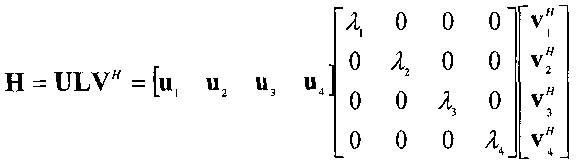
왜냐하면 desired PM는 수신 SINR을 최대화 하기 위해서 채널 H의 채널 gain을 최대화 할 수 있는 방향으로 설정되었기 때문에 간섭신호는 이 PM의 방향을 회피하여 선택하는 것이 간섭 완화에 효과적이기 때문이다. 채널 H를 singular value decomposition ( SVD )을 통해 복수개의 independent channel로 분석해 보면 이러한 BCPMI 결정 방식은 더욱 정당화된다. 4x4 채널 H는 아래 수학식 15와 같이 SVD를 통해 분해할수 있다.
15]
Figure imgf000059_0001
수학식 15에서 U'V는 unitary 행렬이며, L , VI λ는 각각 채널 Η의 4x1 left singular vector, 4x1 right singular vector, s ingular value를 나타내며, λ' > ' 로 내림차순으로 정렬되어 있다. 송신 단에서 beamf orming matrix v≤f 수신 단에서 beamforming matrix U"를 용할 경우 이론적으로 얻을 수 있는 모든 채널 gain을 손실 없이 얻을 수 있다.
Rank 1인 경우는 송신 beamforming vector Vi과 수신 beamforming vector ul을 사용하는 것이 채널 gain I시 2을 얻어 SNR 관점에서 최적의 성능을 얻을 수 있다. 예를 들어 UE-A는 rank 1인 경우 ^과 가장 유사한 PM를 선택하는 것이 유리하다. 이상적으로 desired PM가 ^과 완전히 일치하는 경우 수신 beam올 Ul으로 설정하고 간섭 신호의 송신 beam은 PM에 orthohonal한 방향으로 설정하여 desired 신호에 손실 없이 간섭 신호를 완벽히 제거할 수 있다. 현실적으로 양자화 오류로 인해 desired PM가 ^과 약간의 차이가 있는 경우, PM에 orthogonal한 방향으로 설정된 간섭 신호의 송신 beam은 7丄에 orthogonal한 beam과 더 이상 동일하지 않기 때문에 desired 신호에 손실 없이 간섭 신호를 완벽히 제거 할 수 없지만, 양자화 오차가 작은 경우 간섭 신호 제어에 도움을 줄 수 있다.
Implicit 피드백의 일 예로 LTE codebook올 人 ]·용하는 경우 BCPMI는 PMI에 대해 orthogonal한 vector ind.ex로 static하게 결정될 수 있다. 송신 안테나가 4개 이고 PMI를 피드백 한 UE의 수신 rank를 1로 가정하였고 desired PMI에 대해 orthogonal한 3개의 vector는 3개의 BCPM工로 표현된다.
예를 들어 PMI = 3인 경우, BCPMI=0 , 1 , 2로 결정된다. PMI와 BCPMI는 codebcxik내에 있는 4x1 vector codeword의 인텍스를 나타낸다. 기지국은 상기 BCPMI set ( BCPMI=0 , 1 , 2 )을 간섭 제거에 유효한 precoding index로 간주하여 일부 또는 전부를 co-schedule UE의 precoder로 사용한다.
Implicit PMI의 장점은 desired PMI와 BCPMI set이 1 : 1로 mapping되어 있으므로 추가적인 피드백 overhead가 없다는 것이다. 하지만 desired PM ( PM : PMI에 해당하는 precoding matrix ) 양자화 오차로 인해 그에 종속된 BCPM 역시 최적의 간섭제거 beam 방향과 오차가 있을 수 있다. 양자화 오차가 없다면 3개의 BCPM는 모두 간섭을 완벽히 제거하는 간섭 beam ( ideal 간섭 beam)올 나타내지만, 오차가 있을 경우 각 BCPM는 ideal 간섭 beam과 차이가 발생한다.
또한, 각 BCPM 가 갖는 ideal 간섭 beam과의 차이는 평균적으로 같지만, 특정 순간에는 다를 수 있다. 예를 들어 desired PMI=3일 경우 BCPMI 0 , 1 , 2의 순서로 간섭 신호 제거에 효과적일 수 있으며, BCPMI 0 , 1 , 2의 상대적인 오차를 모르는 기지국은 ideal 간섭 beam과 오차가 가장 큰 BCPMI 2를 간섭 신호의 beam으로 정하여 co-scheduled UE간 강한 간섭이 존재하는 상태로 통신 할 가능성이 있다.
D2D (Device - to-Device) 통신 일반
Device-to-Device ( D2D) 통신 기술이란 기지국과 같은 인프라를 거치지 않고 지리적으로 근접한 단말들이 직접적으로 통신하는 방식을 말한다. D2D 통신 기술은 이미 상용화가 이루어진 와이파이 다이렉트 (Wi-Fi Direct ) , 블루투스 (Bluetooth)와 같이 주로 비면허 주파수 대역을 사용하는 기술이 개발되었다. 하지만 샐를러 시스템의 주파수 이용 효율을 향상시키기 위한 목적으로 면허 주파수 대역을 활용한 D2D 통신 기술 개발과 표준화가 진행 중에 있다.
일반적으로 D2D 통신은 사물과 사물 간의 통신이나 사물 지능 통신을 지칭하는 용어로 제한적으로 사용되기도 하지만, 본 발명에서의 D2D 통신은 통신 기능이 장착된 단순한 장치는 물론, 스마트폰이나 개인용 컴퓨터와 같이 통신 기능을 갖춘 다양한 형태의 장치 간의 통신을 모두 포함할 수 있다.
도 18은 본 발명이 적용될 수 있는 무선 통신 시스템에서 D2D 통신을 개념적으로 설명하기 위한 도면이다.
도 18의 (a)는 기존의 기지국 증심의 통신 방식을 나타내는 것으로, 단말 KUE 1)은 상향링크 상에서 기지국으로 데이터를 전송할 수 있고, 기지국은 하향링크 상에서 단말 2(UE 2)로 데이터를 전송할 수 있다. 이러한 통신 방식은 기지국을 통한 간접 통신 방식이라고 할 수 있다 . 간접 통신 방식에서는 기존의 무선 통신 시스템에서 정의된 링크인 Un 링크 (기지국들 간의 링크 또는 기지국과 증계기 간의 링크로서, 백홀 링크라고 칭할 수 있음) 및 /또는 Uu 링크 (기지국과 단말 간의 링크 또는 중계기와 단말 간의 링크로서 , 액세스 링크라고 칭할 수 있음)가 관련될 수 있다.
도 18의 (b)는 D2D 통신의 일례로서 단말 대 단말 (UE-to-UE) 통신 방식을 나타내는 것으로, 단말 간의 데이터 교환이 기지국을 거치지 않고 수행될 수 있다. 이러한 통신 방식은 장치 간의 직접 통신 방식이라고 할 수 있다. D2D 직접 통신 방식은 기존의 기지국을 통한 간접 통신 방식에 비하여 지연 (latency)이 줄어들고, 보다 적은 무선 자원을 사용하는 등의 장점을 가진다.
도 19는 본 명세서에서 제안하는 방법이 적용될 수 있는 D2D 통신의 다양한 시나리오들의 일례를 나타낸다.
D2D 통신의 시나리오는 단말 1과 단말 2가 셀 커버리지 내 (in- coverage)/셀 커버리지 out— of—coverage)에 위치하는지에 따라 크게 (1) Out-of -Cover age Network, (2) Partial -Coverage Network 및 (3) In— Coverage Network으로 나 수 있다. In-Coverage Network의 경우, 기지국의 커버리지에 해당하는 샐 (Cell)의 개수에 따라 In-Coverage-Single-Cell 및 In— Coverage一 Multi-Cell로 나 수 있다.
도 19의 (a)는 D2D 통신의 Out-of-Coverage Network 시나리오의 일 예를 나타낸다.
Out-of-Coverage Network 시나리오는 기지국의 제어 없이 D2D 단말들 간 D2D 통신을 수행하는 것을 말한다.
도 19의 (a)에서 , 단말 1과 단말 2만 존재하며 , 단말 1과 단말 2는 직접 통신을 하는 것을 볼 수 있다.
도 19의 (b)는 D2D 통신의 Partial-Coverage Network 시나리오의 일 예를 나타낸다.
Partial-Coverage Network 시나리오는 네트워크 커버리지 내에 위치하는 D2D 단말과 네트워크 커버리지 밖에 위치하는 D2D 단말 간에 D2D 통신을 수행하는 것을 말한다.
도 19의 (b)에서, 네트워크 커버리지 내 위치하는 단말 1과 네트워크 커버리지 밖에 위치하는 단말 2가통신하는 것을 블 수 있다.
도 19의 (c)는 In-Coverage-Single-Cell 시나리오의 일 예를, 도 19의 (d)는 In-Coverage-Multi-Cell 시나리오의 일 예를 나타낸다.
In-Coverage Network 시나리오는 D2D 단말들이 네트워크 커버리지 내에서 기지국의 제어를 통해 D2D통신을 수행하는 것을 말한다.
도 19의 (c)에서 , 단말 1과 단말 2는 동일한 네트워크 커버리지 (또는 셀) 내에 위치하며 , 기지국의 제어 하에 D2D 통신을 수행한다 .
도 19의 (d)에서, 단말 1과 단말 2는 네트워크 커버리지 내에 위치하기는 하나, 서로 다른 네트워크 커버리지 내에 위치한다. 그리고, 단말 1과 단말 2는 각 네트워크 커버리지를 관리하는 기지국의 제어 하에 D2D통신을 수행한다. 이하, D2D 통신에 관하여 보다상세히 살펴본다 . -
D2D 통신은 도 19에 도시된 시나리오에서 동작할 수 있으나, 일반적으로 네트워크 커버리지 내 (in-coverage)와 네트워크 커버리지 밖 (out-of- coverage)에서 동작할 수 있다. D2D 통신 (단말들 간 직접 통신 )을 위해 이용되는 링크를 D2D 링크 (D2D link) , 다이렉트 링크 (directlink) 또는 사이드 링크 (sidelink) 등으로 지칭할 수 있으나, 이하 설명의 편의를 위해 사이드 링크로 통칭하여 설명한다.
사이드 링크 전송은 FDD의 경우 상향링크 스펙트럼에서 동작하고, TDD의 경우 상향링크 (혹은 하향링크) 서브프레임에서 동작할 수 있다. 사이드 링크 전송과 상향링크 전송의 다중화를 위하여 TDM(Time Division Multiplexing) °1 이용될 수 있다.
사이드 링크 전송과 상향링크 전송은 동시에 일어나지 않는다. 상향링크 전송을 위해 사용되는 상향링크 서브프레임 또는 UpPTS와 부분적으로 혹은 전체적으로 겹쳐지는 사이드 링크 서브프레임에서는 사이드 링크 전송이 일어나지 않는다. 또한, 사이드 링크의 전송 및 수신 또한 동시에 일어나지 않는다.
사이드 링크 전송에 이용되는 물리 자원의 구조는 상향링크 물리 자원의 구조가 동일하게 이용될 수 있다. 다만, 사이드 링크 서브프레임의 마지막 심블은 보호 구간 (guard period)으로 구성되어 사이드 링크 전송에 이용되지 않는다.
사이드 링크 서브프레임은 확장 순환 전치 (extended CP) 또는 일반 순환 전치 (normal CP)에 의해 구성될 수 있다.
D2D 통신은 크게 디스커버리 (discovery) , 직접 통신 (direct communication) , 동기화 (SynchronizatiOTi)로 구분될 수 있다.
1) 디스커버리 (discovery)
D2D 디스커버리는 네트워크 커버리지 내에서 적용될 수 있다. (Inter- cell, Intra-cell 포함) . 인터 셀 ( inter-cell ) 디스커버리에서 동기화된 (synchronous) 또는 동기화되지 않은 (asynchronous) 샐 배치 모두 고려될 수 있다. D2D 디스커버리는 근접 영역 내의 단말에게 광고, 쿠폰 발행, 친구 찾기 등의 다양한 상용 목적으로 활용될 수 있다.
단말 1이 디스커버리 메시지 전송의 역할 (roie)을 가지는 경우, 단말 1은 디스커버리 메시지를 전송하고, 단말 2는 디스커버리 메시지를 수신한다. 단말
1과 단말 2의 전송 및 수신 역할은 바뀔 수 있다. 단말 1으로부터의 전송은 단말 2와 같은 하나 이상의 단말 (들)에 의해 수신될 수 있다.
디스커버리 메시지는 단일의 MAC PDU를 포함할 수 있으며, 여기서 단일의 MAC PDU는 단말 ID 및 application ID를 포함할수 있다.
디스커버리 메시지를 전송하는 채널로 물리 사이드 링크 디스커버리 채널 (PSDCH:. Physical Sidelink discovery Channel)이 정의될 수 있다. PSDCH 채널의 구조는 PUSCH 구조를 재이용할수 있다.
D2D 디스커버리를 위한 자원 할당 방법은 두 가지의 타입 (Type 1, Type 2)이 이용될 수 있다.
타입 1의 경우, 기지국은 단말 특정하지 않은 (non-UE specific) 방식으로 디스커버리 메시지 전송을 위한자원을 할당할 수 있다.
구체적으로, 특정 주기 (이하, 、디스커버리 주기' ) 내에서 복수의 서브프레임 세트 및 복수의 자원 블록 세트로 구성된 디스커버리 전송 및 수신을 위한 무선 자원 풀 (pool)이 할당되고, 디스커버리 전송 단말은 이 무선 자원 풀 (pool) 내에서 특정 자원을 임의로 선택한 다음 디스커버리 메시지를 전송한다.
이러한 주기적인 디스커버리 자원 풀 (pool)은 반정적 (semi-static)인 방식으로 디스커버리 신호 전송을 위해 할당될 수 있다. 디스커버리 전송을 위한 디스커버리 자원 풀 (pool)의 설정 정보는 디스커버리 주기 , 디스커버리 주기 내 디스커버리 신호의 전송을 위해 사용할 수 있는 서브프레임 세트 및 자원 블톡 세트 정보 둥을 포함한다 . 이러한, 디스커버리 자원 풀의 설정 정보는 상위 계층 시그널링에 의해 단말에 전송될 수 있다. In— coverage 단말의 경우, 디스커버리 전송을 위한 디스커버리 자원 풀 (pool)은 기지국에 의해 설정되고, RRC 시그널링 (예를 들어 , SIB (System Information Block) )을 이용하여 단말에게 알려줄 수 이다.
하나의 디스커버리 주기 내에 디스커버리를 위해 할당된 디스커버리 자원 풀 (pool)은 동일한 크기를 가지는 시간-주파수 자원 블록으로 TDM 및 /또는 FDM으로 다중화될 수 있으며, 이러한 동일한 크기를 가지는 시간-주파수 자원 블록을 、디스커버리 자원 (discovery resource) '으로 지칭할 수 있다. 디스커버리 자원은 하나의 서브프레임 단위로 구분될 수 있으며, 각 서브프레임에서 슬롯 당 두 개의 물리 자원 블록 (PRB)을 포함할 수 있다.하나의 디스커버리 자원은 하나의 단말에 의해 디스커버리 MAC PDU의 전송을 위해 사용될 수 있다. 또한, 단말은 하나의 전송 블톡 (transport block)의 전송을 위해 디스커버리 주기 내에서 디스커버리 신호를 반복적으로 전송할 수 있다. 하나의 단말에 의해 전송되는 MAC PDU의 전송은 디스커버리 주기 내 (즉, 무선 자원 풀 (pool) )에서 연속적으로 (contiguous) 혹은 비연속적 (noncontiguous )으로 반복 (예를 들어 , 4회 반복)될 수 있다. 하나의 전송 블록을 위한 디스커버리 신호의 전송 횟수는 상위 계층 시그널링에 의해 단말에 전송될 수 있다.
단말은 MAC PDU의 반복되는 전송을 위해 사용될 수 있는 디스커버리 자원 세트 (discovery resource set)에서 첫 번째 디스커버리 자원을 임의로 선택하고, 그 이외의 디스커버리 자원은 첫 번째 디스커버리 자원과 관련하여 결정될 수 있다. 예를 들어, 일정 패턴이 미리 설정되고, 단말이 첫 번째로 선택한 디스커버리 자원의 위치에 따라 그 다음의 디스커버리 자원이 미리 설정된 패턴에 따라 결정될 수 있다. 또한, 단말이 MAC PDU의 반복되는 전송을 위해 사용될 수 있는 디스커버리 자원 세트 내에서 각각의 디스커버리 자원을 임의로 선택할 수도 있다.
타입 2는 디스커버리 메시지 전송을 위한 자원이 단말 특정 (UE specific)하게 할당된다. 타입 2는 다시 타입 2A (Type-2A) , 타입 2B(Type- 2B)로 세분화된다. 타입 2A는 기지국이 디스커버리 주기 내에서 단말이 디스커버리 메시지의 전송 시점 (instance)마다 자원을 할당하는 방식이고, 타입 2B는 반정적인 (semi-persistent) 방식으로 자원을 할당하는 방식이다. 타입 2B의 경우, RRC_CONNECTED 단말은 RRC 시그널링을 통해 기지국에 D2D 디스커버리 메시지의 전송을 위한 자원의 할당을 요청한다 . 그리고, 기지국은 RRC 시그널링을 통해 자원을 할당할 수 있다. 단말은 RRC— IDLE 상태로 천이할 때 또는 기지국이 RRC 시그널링을 통해 자원 할당을 철희 (withdraw)할 때, 단말은 가장 최근에 할당된 전송 자원을 해제한다. 이와 같이 타입 2B의 경우, RRC 시그널링에 의해 무선 자원이 할당되고, PDCCH에 의해 할당된 무선 자원의 활성 (activation) /비활성 (deactivation)이 결정될 수 있다.
디스커버리 메시지 수신을 위한 무선 자원 풀 (pool)은 기지국에 의해 설정되고, RRC 시그널링 (예를 들어, SIB(System Information Block) )을 이용하여 단말에게 알려줄 수 있다 .
디스커버리 메시지 수신 단말은 디스커버리 메시지 수신을 위하여 상술한 타입 1 및 타입 2의 디스커버리 자원 풀 (pool) 모두 모니터링한다.
2) 직접 통신 (direct communication)
D2D 직접 통신의 적용 영역은 네트워크 커버리지 안깎 (in-coverage, out-of-coverage)은 물론 네트워크 커버리지 경계 영역 (edge-of- coverage)도 포함한다. D2D 직접 통신은 PS (Public Safety) 등의 목적으로 이용될 수 있다.
단말 1이 직접 통신 데이터 전송의 역할을 가지는 경우, 단말 1은 직접 통신 데이터를 전송하고, 단말 2는 직접 통신 데이터를 수신한다. 단말 1과 단말 2의 전송 및 수신 역할은 바¾ 수 있다. 단말 1으로부터의 직접 통신 전송은 단말 2와 같은 하나 이상의 단말 (들)에 의해 수신될 수 있다.
D2D 디스커버리와 D2D 통신은 서로 연계되지 않고 독립적으로 정의될 수 있다. 즉, 그룹캐스트 (groupcast) 및 브로드캐스트 (broadcast) 직접 통신에서는 D2D 디스커버리가 요구되지 않는다. 이와 같이, D2D 디스커버리와 D2D 직접 통신이 독립적으로 정의되는 경우, 단말들은 인접하는 단말을 인지할 필요가 없다. 다시 말해, 그룹캐스트 및 브로드캐스트 직접 통신의 경우, 그룹 내 모든 수신 단말이 서로 근접할 것을 요구하지 않는다.
D2D 직접 통신 데이터를 전송하는 채널로 물리 사이드 링크 공유 채1 i (PSSCH: Physical Sidelink Shared Channel)이 정의될 수 있다. 또한, D2D 직접 통신을 위한 제어 정보 (예를 들어 , 직접 통신 데이터 전송을 위한 스케줄링 승인 (SA: scheduling assignment) , 전송 형식 등)를 전송하는 채널로 물리 사이드 링크 제어 채널 (PSCCH: Physical Sidelink Control Channel) °} 정의될 수 있다. PSSCH 및 PSCCH는 PUSCH 구조를 재이용할 수 있다.
D2D 직접 통신을 위한 자원 할당 방법은 두 가지의 모드 (mode 1, mode 2)가 이용될 수 있다.
모드 1은 기지국이 단말에게 D2D 직접 통신을 위한 데이터 또는 제어 정보를 전송하기 위하여 사용하는 자원을 스케줄링 하는 방식을 말한다. in- coverage에서는 모드 1이 적용된다. 기지국은 D2D 직접 통신에 필요한 자원 풀 (pool)을 설정한다. 여기서 , D2D 통신에 필요한 자원 풀 (pool)은 제어 정보 풀과 D2D 데이터 풀로 구분될 수 있다. 기지국이 PDCCH 또는 ePDCCH를 이용하여 송신 D2D 단말에게 설정된 풀 내에서 제어 정보 및 D2D 데이터 전송 자원을 스케줄링하면 송신 D2D 단말은 할당된 자원을 이용하여 제어 정보 및 D2D 데이터를 전송한다.
전송 단말은 기지국에 전송 자원을 요청하고, 기지국은 제어 정보와 D2D 직접 통신 데이터의 전송을 위한 자원을 스케줄링한다. 즉, 모드 1의 경우, 전송 단말은 D2D 직접 통신을 수행하기 위하여 RRC_CONNECTED 상태에 있어야 한다ᅳ 전송 단말은 스케줄링 요청을 기지국에 전송하고, 이어 기지국이 전송 단말에 의해 요청되는 자원의 양을 결정할 수 있도록 BSR(Buffer Status Report) 절차가 진행된다.
수신 단말들은 제어 정보 풀을 모니터링하고, 자신과 관련된 제어 정보를 디코딩하면 해당 제어 정보와 관련된 D2D 데이터 전송을 선택적으로 디코당할 수 있다. 수신 단말은 제어 정보 디코딩 결과에 따라 D2D 데이터 풀을 디코딩하지 않을 수도 있다.
모드 2는 단말이 D2D 직접 통신을 위한 데이터 또는 제어 정보를 전송하기 위하여 자원 풀 (pool)에서 특정 자원을 임의로 선택하는 방식을 말한다. o it- of-coverage 및 /또는 edge—of-coverage에서 모드 2가 적용된다.
모드 2에서 제어 정보 전송훌 위한자원 풀 (pool) 및 /또는 D2D 직접 통신 데이터 전송을 자원 풀 (pool)은 미리 설정 (pre-configured)되거나 반정적으로 (semi-statically) 설정될 수 있다. 단말은 설정된 자원 풀 (시간 및 주파수)를 제공 받고, 자원 풀에서 D2D 통신 전송을 위한 자원을 선택한다. 즉, 단말은 제어 정보를 전송하기 위하여 제어 정보 자원 풀에서 제어 정보 전송을 위한 자원을 선택할 수 있다. 또한, 단말은 D2D 직접 통신 데이터 전송을 위해 데이터 자원 풀에서 자원을 선택할 수 있다.
D2D 브로드캐스트 통신에서, 제어 정보는 브로드캐스팅 단말에 의해 전송된다. 제어 정보는 D2D 직접 통신 데이터를 운반하는 물리 채널 (즉, PSSCH)과 관련하껴 데이터 수신을 위한 자원의 위치를 명시적으로 (explicit) 및 /또는 묵시적으로 (implicit) 지시한다.
3) 동기화 ( synchronization) D2D 동기 신호 (D2DSS: D2D Synchronization Signal/sequence)는 단말이 시간-주파수 동기를 획득하기 위하여 이용될 수 있다. 특히, 네트워크 커버리지 밖의 경우 기지국의 제어가 불가능하므로 단말 간 동기 확립을 위한 새로운 신호 및 절차가 정의될 수 있다. D2D 동기 신호는 사이드 링크 동기 신호 (Sidelink Synchronization signal)로 지칭할 수 있다.
D2D 동기 신호를 주기적으로 전송하는 단말을 D2D 동기 소스 (D2D Synchronization Source) 또는 사이드 링크 동기 소스 (Sidelink Synchronization Source) 등으로 지칭할 수 있다. D2D 동기 소스가 기지국인 경우, 전송되는 D2D 동기 신호의 구조는 PSS/SSS와 동일할 수 있다. D2D 동기 소스가 기지국이 아닌 경우 (예를 들어 , 단말 또는 GNSS (Global Navigation Satellite System) 등) 전송되는 D2D 동기 신호의 구조는 새롭게 정의될 수 있다.
D2D 동기 신호는 40ms 보다 작지 않은 주기를 가지고 주기적으로 전송된다 . 단말 별로 다중의 물리 계충 D2D 동기 식별자 (physical-layer D2D synchronization identity)를 가질 수 있다. 물리 계층 D2D 동기 식별자는 물리 계층 사이드 링크 동기 식별자 (physical-layer sidelink synchronization identity) 또는 간단하게 D2D 동기 식별자로 지칭될 수도 있다.
D2D 동기 신호는 D2D 프라이머리 동기 신호 (primary synchronization signal/sequence)와 D2D 세컨더리 동기 신호 (secondary synchronization signal/sequence)를 포함한다. 이를 각각 프라이머리 사이드 링크 동기 신호 (primary sidelink synchronization signal ) 및 세¾더리 λ}°1― 링크 동기 신호 (secondary sidelink synchronization signal)로 지칭할 수 있다.
D2D 동기 신호를 전송하기 전에, 먼저 단말은 D2D 동기 소스를 탐색할 수 있다. 그리고, D2D 동기 소스가 탐색되면, 단말은 탐색된 D2D 동기 소스로부터 수신된 D2D 동기 신호를 통해 시간-주파수 동기를 획득할 수 있다. 그리고, 해당 단말은 D2D 동기 신호를 전송할수 있다.
또한, 동기화 함께 단말 간 통신에 샤용되는 필수 정보를 전달하는 목적의 채널이 필요할 수 있으며, 이러한 목적의 채널이 정의될 수 있다. 이러한 채널을 물리 D2D 동기 채널 (PD2DSCH: Physical D2D Synchronization Channel) 또는 물리 사이드 링크 방송 채널 (PSBCH: Physical Sidelink Broadcast Channel)로 지칭할 수 있다.
이하에서는 명료성을 위해 D2D 통신에 있어서 2개의 장치들 간의 직접 통신을 예로 들어 설명하지만, 본 발명의 범위가 이에 제한되는 것은 아니고, 2 이상의 복수의 장치들 간의 D2D 통신에 대해서도 본 발명에서 설명하는 동일한 원리가 적용될 수 있다. 간섭 측정 기반 D2D자원 할당방법
셀를러 시스템에서 근접한 거리의 단말들이 D2D 통신을 하면 기지국의 부하를 분산 시킬 수 있으며, 상대적으로 단거리를 전송함으로써 단말의 전력 소모를 줄일 수 있고, 전송 지연 (Latency) 또한 줄일 수 있는 장점이 있다. 전체 시스템 관점에서는 기존의 샐를러 단말과 D2D 단말이 동일한 주파수를 공유하여 공간적으로 주파수를 재사용함으로써 주파수 이용 효율을 향상시키는 효과가 있다. 뿐만 아니라 단말 간 릴레이에 활용할 수 있고, 모바일 사용자의 위치를 중심으로 인접한 거리에 있는 상점 및 물건의 정보를 수집하거나 실내에서의 정밀한 측위, 인접한 거리의 사람들 간의 그룹 통신, 네트워크 게임, 위치기반광고 등과 같이 신규 근접성 기반서비스를 창출하는 효과가 기대된다. 셀롤러 기반 D2D 통신이 비면허 주파수 대역에서의 D2D 통신과 차별화되는 부분은 기지국이 자원할당올 포함한 D2D통신 제어에 관여할 수 있다는 점이다. 셀를러 기반 D2D 통신은 아래 도 20와 같이 기지국의 개입 정도에 따라 세 가지 형태로 분류할 수 있다.
도 20은 셀롤러 네트워크에서의 D2D 통신의 자원 할당 방식을 예시하는 도면이다.
도 20 (a)는 기지국의 전혀 개입하지 않는 분산형 (Distributed) D2D 방식을 예시하고, 도 20(b)는 제어 신호는 기지국을 통해 전달하고 데이터 신호만 직접 전달하는 중앙 집중형 (Centralized) D2D 방식 , 도 20(c)는 일부 제어 신호는 기지국을 통해 전달하고 일부는 직접 전달하는 혼합형 (Hybrid) D2D로 분류할수 있다.
분산형 D2D 방식의 경우, D2D 단말이 주변 간섭을 인지하여 스스로 자원을 할당하는 방식으로 기지국이 받는 부하는 없지만 샐를러 사용자의 자원할당이 동적으로 변하기 때문에 D2D 단말이 이를 제어하는데 어려움이 있다. 중앙 집증형 방식은 기지국이 링크들의 채널정보 또는 거리정보를 수집하여 이를 토대로 D2 D 자원을 할당하는 방식으로 성능은 우수하나 신호 처리의 부하가 크고 재난 상황과 같이 기지국이 제 기능을 하지 못하는 상황에서는 적용하기 어려운 단점이 있다.
따라서 , 이하 본 발명에서는 중앙 집중형과 분산형 D2 D의 단점을 보안할 수 있는 흔합형 D2 D 통신 기술을 기반으로 하는 셀를러 상향링크에서 간섭인지 기반 D2D 통신 기술을 제안한다.
본 발명에서는 D2 D 단말이 샐를러 자원을 공유하기 위하여 셀를러 단말로부터 받는 간섭의 크기를 측정함으로써, 최적의 통신 성능을 얻을 수 있는 자원을 결정하는 방법을 제안한다.
이와 같은, 셀를러 단말로부터 받는 간섭을 측정하기 위한 간섭 인지 기술 중 스펙트럼 센싱 ( Spectrum Sensing)은 인지 무선 ( Cognitive Radio ) 시스템에서 부사용자 (예를 들어 , D2D 단말)가 주사용자 (예를 들어 , 셀를러 단말)의 스펙트럼 사용 여부를 판단하기 위한 기술로 에너지 검출, 신호 특성 검출 등이 대표적인 방법이다.
도 21은 본 발명의 일 실시예에 따른 D2D 단말로부터 셀를러 단말의 거리에 따른 간섭의 크기를 예시하는 도면이다.
도 21을 참조하면, D2D 신호 (예를 들어 , D2D 디스커버리 메시지 /신호 또는 D2D 직접 통신을 위한 제어 정보 또는 데이터 )를 수신하는 D2D 단말 (이하, ' D2D Rx 단말' )은 샐를러 단말이 상향링크 전송을 위해 사용하는 자원의 간섭의 크기를 측정한다. 도 21에서 D2D Rx 단말로 향하는 화살표는 D2 D Rx 단말에 발생되는 간섭을 나타내고, 화살표의 두께는 D2D Rx 단말이 받는 간섭의 크기를 나타낸다.
셀를러 단말들이 동일한 송신 전력을 사용하고, 거리에 따른 경로손실 (path los s )만 고려하는 경우 D2 D 수신단에서 가장 멀리 떨어진 셀를러 단말에 할당된 자원 (즉, 자원 블록 ( RB ) )에서 가장 적은 간섭이 측정될 것이다. 즉, 도 21에서 최상단에 위치하는 단말에 할당된 자원에서 가장 적은 간섭이 측정될 것이다. 물론 실제 환경에서는 셀를러 단말마다송신 전력이 다르고 새도우 (Shadow) 효과 및 페이딩 (Fading)의 영향으로 최적의 RB에 해당되는 셀를러 단말이 단순히 가장 가까운 샐를러 단말이 아닐 수도 있다. 하지만 채널 상황이 변하지 않는다면 간섭 인지 과정에서 간섭이 가장 적다고 판단된 자원을 공유하는 것이 가장 바람직하다.
본 발명에서는 샐를러 단말에 대한 자원 할당은 스케줄링 주기 (예를 들어, 서브프레임 )로 변하기 때문에 D2D 단말이 간섭이 가장 적은 자원을 탐색하는 과정에서 찾은 자원이 무의미해지는 문제점이 발생할 수 있다. 즉, D2D Rx 단말이 간섭이 가장 적은 자원을 탐색하는 시간과 실제 D2D 신호 (예를 들어 , D2D 디스커버리 메시지 /신호 또는 D2D 직접 통신을 위한 제어 정보 또는 데이터 )를 전송하는 D2D 단말 (이하, 'D2D Tx 단말')이 할당된 자원을 사용하는 시간과의 갭 (gap)이 존재하므로, 동일한 자원이 서로 다른 셀를러 단말에게 할당될 수 있기 때문이다.
또한, 셀를러 단말이 기지국으로부터 상향링크 자원을 할당 받는 시점과 셀를러 단말이 상향링크를 전송하는 시점과도 갭 (gap)이 존재하므로, D2D 단말이 간섭이 가장 적은 자원을 탐색하는 과정에서 찾은 자원이 무의미해질 수도 있다.
이하, 기지국에 의한 단말의 상향링크 자원 할당 (UL grant)와 단말의 상향링크 데이터 (PUSCH) 전송 타이밍 관계를 살펴본다.
도 22는 본 발명이 적용될 수 있는 FDD 기반 무선 통신 시스템에서 상향링크 자원 할당 (UL grant)과 상향링크 데이터 전송 (PUSCH) 간의 전송 시점을 예시한 도면이다.
도 22를 참조하면 , 단말이 기지국으로부터 상향링크 자원 할당 (UL grant) (즉, DCI 포맷 0/4를 가지는 PDCCH/EPDCCH) 및 /또는 PHICH를 하향링크 캐리어의 n번째 서브프레임에서 수신하였을 경우, 단말은 상향링크 캐리어의 n+4번째 서브프레임에서 PUSCH를 전송한다.
반면, TDD 무선 프레임 구조에서는 하향링크 /상향링크 서브프레임 구성이 상향링크-하향링크 구성 (configuration) (표 1 참조) 별로 다르기 때문에 PUSCH 및 PHICH 전송 시간은 상향링크-하향링크 구성에 따라 다르게 설정되며 , PUSCH 및 PHICH의 전송시간은 서브프레임의 인덱스 (또는 숫자)에 따라 서로 다르게 구성될 수 있다.
LTE /LTE-A 시스템에서, PUSCH와 이에 선행하는 PDCCH ( UL grant 포함하는) , 그리고 PUSCH에 대응되는 하향링크 HARQ ACK/NACK이 전송되는 PHICH의 상 /하향링크 타이밍 관계는 미리 정해져 있다.
표 6은 상향링크-하향링크 구성 별로 PDCCH와 이에 대응되는 PUSCH의 전송 타이밍을 나타내는 표이다.
【표 6】
Figure imgf000072_0001
표 6을 참조하면, 상향링크―하향링크 구성 1 내지 6의 경우, 단말이 기지국으로부터 UL grant (즉, DCI 포맷 0 / 4를 가지는 PDCCH/EPDCCH ) 및 /또는 PHICH를 n번째 하향링크 서브프레임에서 수신하였을 경우, 단말은 PDCCH/E PDCCH 및 /또는 PHICH가 전송된 하향링크 서브프레임 인텍스에 대응되는 n+k번째 상향링크 서브프레임에서 PUSCH를 전송한다. 이때, k값은 표 6과 같다.
이러한 문제점을 해결하기 위해 본 발명에서는 기지국에 도움을 받아 D2 D 단말의 최적 자원 (즉, 간섭이 가장 적은 자원)올 탐색한 시간과 동일한 시간에서 해당 자원을 할당 받은 셀를러 단말을 기준으로 동기화된 스케줄링을 통하여 D2 D 및 샐를러 자원 할당을 수행한다.
이하, 본 명세서에서 '자원 '은 디스커버리 메시지 /신호 전송을 위한 자원 (즉, PSDCH 자원) 또는 D2 D 직접 통신을 위한 데이터 또는 제어 정보를 전송하기 위한 자원 (즉, PSSCH 자원 )을 의미한다 . 즉, 디스커버리 메시지 /전송의 경우 타입 2를 가정하여 설명하고, D2 D 직접 통신의 경우 모드 1을 가정하여 설명한다. 따라서, 이하 디스커버리 메시지 /신호 및 D2 D 직접 통신을 위한 데이터 /제어 정보를 ' D2 D신호'로 통칭하여 설명한다. 또한, 이하 본 명세서에서 '자원 '은 단말에게 특정된 자원을 의미할 수도 있으나, 해당 단말이 사용 가능한 자원 후보의 집합 즉, 자원 풀 ( resource pool )로 해석될 수도 있다.
다만, 설명의 편의를 위해 D2D 단말 및 샐를러 단밀:에 하나의 스케즐링 시간 단위 (즉, 스케줄링 주기 )에서는 하나의 자원 블록 ( RB)이 할당된다고 가정하여 설명한다 . 다만, 본 발명이 이에 한정되는 것은 아니며 하나의 시간 단위에서 복수의 자원 블톡이 할당될 수 있음은 물론이다.
한편 , D2D 수신 단말 ( D2D Rx 단말)에서 셀를러 단말이 사용하는 자원에서 간섭을 측정하는 시간 (즉, 자원 탐색에 소요되는 시간)과 D2D Rx 단말이 측정된 결과를 기지국에 보고하는데 걸리는 피드백 지연은 기본적으로 셀를러 단말의 CQI ( Channel Quality Indicator ) 측정 및 피드백 지연과 동일하다고 가정할 수 있다.
따라서 , CQI 수준의 정확도를 갖는 간섭 측정이 가능하며 피드백 지연에 의한 채널 변화는 미약하다고 할 수 있다. 3GPP LTE/LTE-A 규격에 따르면, CQI 피드백 지연은 4개의 서브프레임 구간, 즉 4ms이다. 이는 단말이 l OOkm/hr의 속도로 이동하는 경우 약 11cm의 거리를 움직이는 시간으로 피드백 지연에 따른 채널 변화는 미미할 것으로 예상된다.
도 23은 본 발명의 일 실시예에 따른 D2D 통신을 위한 자원 할당 방법을 예시하는 도면이다.
도 23을 참조하면, D2 D 수신 단말 ( D2D Rx 단말)은 간섭 인지 기술을 이용하여 주변 단말로부터 셀를러 자원의 간섭의 크기를 측정하여 D2 D 링크와 공유하기에 가장 적합한 샐를러 자원을 결정한다 ( S2301 ) .
D2D Rx 단말 측면에서 D2D 신호를 수신할 때 샐롤러 단말의 상향링크 전송이 간섭으로 수신될 수 있다. 이에 따라, D2D Rx 단말은 셀롤러 단말의 상향링크 자원에서 SNR ( Signal-to-Noise Ratio 또는 SINR ( Signal-to- Interference plus Noise Ratio ) 등을 측정하고, D2D Rx 단말은 측정된 간섭을 기반으로 샐를러 상향링크 자원을 선택한다. 즉, 간섭이 가장 적은 셀를러 상향링크 자원을 선택한다.
D2D Rx 단말은 S2301 단계에서 간섭 인지 기술로부터 결정된 공유 자원 정보와자원 탐색 시간을 기지국에 보고한다 ( S2302 ) . D2D Rx 단말은 간섭이 미리 설정된 임계치 이하로 판단되는 하나 이상의 공유 후보 자원 정보와 자원 탐색 시간을 기지국에 전송할 수도 있다. 이처럼, 하나 이상의 공유 후보 자원 정보를 전송하는 경우, D2D Rx 단말은 각 공유 후보 자원 별로 측정된 간섭 정보를 기지국에 함께 전송할수도 있다.
여기서, 자원 정보는 해당 자원을 특정하기 위한 RB 인텍스로 표시될 수 있으며 , 자원 탐색 시간은 무선 프레임 인덱스 및 /또는 서브프레임 인텍스로 표시될 수 있다.
기지국은 D2D Rx 단말이 자원 탐색올 수행한 시점 (즉, 보고 받은 자원 탐색 시간)에서 동일한 자원 (즉, 보고 받은 공유 자원)이 스케줄링된 셀를러 단말과 D2D 단말의 스케줄링을 동기화한다 ( S2303 ) .
먼저 , 기지국은 D2D Rx 단말로부터 수신한 자원 탐색 시간에서 D2D Rx 단말로부터 수신한 공유 자원이 할당된 샐를러 단말을 확인한다. 이 확인 과정을 위해 기지국은 셀를러 단말에 대한 이전 (서브)프레임의 상향링크 스케줄링 정보를 필요로 하므로 스케줄링 정보를 일정 시간 (예를 들어 , 미리 정해진 시간) 동안 버퍼에 저장해야 한다. 상술한 바와 같이, FDD 시스템의 경우 서브프레임 n에서 상향링크 자원이 할당되면, n+4에서 셀를러 단말이 상향링크 데이터를 전송한다. 또한, TDD 시스템의 경우 샐를러 단말이 상향링크 자원이 할당된 시점으로부터 미리 정해진 시점에 셀를러 단말이 상향링크 데이터를 전송한다 (표 6 참조 ) .
또한, 이와 함께 D2 D 수신 단말 ( D2 D Rx 단말)에서 샐를러 단말이 사용하는 자원에서 간섭을 측정하는 시간 (즉, 자원 탐색에 소요되는 시간)과 D2D Rx 단말이 측정된 결과를 기지국에 보고하는데 걸리는 피드백 지연이 발생된다.
따라서, 예를 들어, 간섭 측정 결과 피드백 지연 시간 + 상향링크 데이터 전송 시점 지연 시간을 합한 시간 동안 기지국은 셀를러 단말의 스케줄링 정보를 저장할수 있다.
그리고, 기지국은 D2 D 단말 ( D2 D x 단말 및 /또는 D2 D Rx 단말)과 해당 셀롤러 단말의 자원 스케줄링을 동기화하여 D2D 단말과 샐를러 단말에 자원을 할당한다. _
여기서 , 동기화는 공유 자원 ( shared resource )을 사용하는 단말들을 페어링 (paring)해서 같은 자원에 지속적으로 스케줄링 ( scheduling)한다는 의미를 포함한다.
기지국은 D2D 단말과 셀를러 단말을 페어링 (pairing)하여 자원 할당 (scheduling)을 수행한다. 페어링은 하나 이상의 D2D 단말과 하나 이상의 셀를러 단말이 자원 할당 측면에서 부분 혹은 전체 자원 공유 방식으로 진행될 수 있다.
기지국은 동기화된 스케줄링 정보를 D2D Tx 단말 및 /또는 D2D Rx 단말에 전송한다 (S2304) .
여기서 , 기지국은 유니캐스트 (unicast) 방식으로 D2D Tx 단말 및 /또는 D2D Rx 단말에 스케줄링 정보를 전송할 수도 있다. 또한, 기지국은 스케줄링 정보를 브로드캐스팅할 수도 있다.
기지국은 셀를러 단말에게 할당되는 자원을 동일하게 D2D x 단말 및 /또는 D2D Rx 단말에 할당하고, 할당된 자원 정보를 샐를러 단말과 D2D 단말 (즉, D2D Tx 단말 및 /또는 D2D Rx 단말)에게 전송할 수 있다. 이 경우, 스케줄링 정보는 자원 할당 정보를 의미할 수 있다.
반면, 기지국은 셀를러 단말과 D2D 단말 (즉, D2D Tx 단말 및 /또는 D2D Rx 단말) 간의 페어링 정보를 셀를러 단말과 D2D 단말 (즉, D2D Tx 단말 및 /또는 D2D Rx 단말)에게 전송할 수 있다. 이 경우, 스케줄링 정보는 페어링 정보를 의미할수 있다.
예를 들어 , 기지국은 셀를러 단말의 식별자 (예를 들어 , C-RNTI 등)와 D2D 단말과의 식별자에 대한 페어링 정보를 브로드캐스팅한다. D2D 단말은 기지국으로부터 전송되는 PDCCH를 모니터링하고, 자신과 페어링된 셀를러 단말의 식별자를 기반으로 해당 샐를러 단말의 하향링크 제어 정보 (DCI)를 확인함으로써, 해당 셀를러 단말에게 할당된 상향링크 자원을 D2D 신호 전송을 위한자원으로사용할 수 있다.
이와 같이, D2D 단말은 자원 탐색 과정에서 간섭이 가장 적은 최적의 샐를러 단말과 동일한 자원을 지속적으로 공유하는 것아 가능하다.
도 24는 본 발명의 일 실시예에 따른 D2D 통신을 위한 자원 할당 방법 및 D2D 신호 전송 방법을 예시하는 도면이다.
도 24를 참조하면, 먼저 D2D 통신을 하고자 하는 D2D Rx는 간섭 인지를 통해 주변 단말로부터 간섭이 적은 자원 탐색올 수행함으로써, 최적의 공유 자원을 판별한다 ( S2401 ) .
앞서 설명한 바와 같이, D2D Rx 단말은 셀를러 단말의 셀를러 단말의 상향링크 자원에서 SNR ( Signal-to-Noise Ratio 또는 SINR ( Signal-to- Interference plus Noise Ratio ) 등을 측정하고, D2D Rx 단말은 측정된 간섭을 기반으로 셀를러 상향링크 자원을 선택한다. 즉, 간섭이 가장 적은 셀를러 상향링크 자원을 선택한다.
D2D Rx 단말은 결정된 공유 자원 정보와 자원 탐색 시간을 기지국에 보고한다 ( S2402 ) .
D2D Rx 단말은 간섭이 미리 설정된 임계치 이하로 판단되는 하나 이상의 공유 후보 자원 정보와 자원 탐색 시간을 기지국에 전송할 수도 있다. 이처럼, 하나 이상의 공유 후보 자원 정보를 전송하는 경우, D2D Rx 단말은 각 공유 후보 자원 별로 측정된 간섭 정보를 기지국에 함께 전송할 수도 있다.
기지국은 D2D Rx 단말이 자원 탐색을 수행한 시점 (즉, 보고 받은 자원 탐색 시간)에서 동일한 자원 (즉, 보고 받은 공유 자원)이 스케줄링된 셀를러 단말과 D2D 단말의 스케줄링을 동기화한다 ( S2403 ) .
먼저, 기지국은 D2 D Rx 단말로부터 수신한 자원 탐색 시간에서 D2 D Rx 단말로부터 수신한 공유 자원이 할당된 셀를러 단말을 확인한다. 상술한 바와 같이 , 이 확인 과정을 위해 기지국은 셀를러 단말에 대한 이전 (서브)프레임의 스케줄링 정보를 일정 시간 동안 버퍼에 저장해야 한다. 예를 들어, 기지국은 간섭 측정 결과 피드백 지연 시간 + 상향링크 데이터 전송 시점 지연 시간을 합한 시간동안 셀를러 단말의 스케줄링 정보를 저장할 수 있다.
그리고, 기지국은 D2D 단말 ( D2D Tx 단말 및 /또는 D2 D Rx 단말)과 해당 샐를러 단말의 자원 스케줄링을 동기화하여 D2 D 단말과 샐를러 단말에 자원을 할당한다.
기지국은 동기화된 스케줄링 정보를 셀를러 단말에 전송하면서 이와 동시에 D2D Tx 단말 및 /또는 D2D Rx 단말에 전송한다 ( S2404 ) .
여기서 , 기지국은 유니캐스트 (unicast ) 방식으로 D2 D Tx 단말 및 /또는 D2D Rx 단말에 스케줄링 정보를 전송할 수도 있다. 또한, 기지국은 스케줄링 정보를 브로드캐스팅할 수도 있다. 상술한 바와 같이 , 기지국은 샐를러 단말에게 할당되는 자원 정보 또는 셀롤러 단말과의 페어링 정보를 스케줄링 정보로써 D2D 단말 (즉, D2D Tx 단말 및 /또는 D2D Rx 단말)에게 전송할수 있다.
D2D TX 단말은 기지국으로부터 수신한 스케줄링 정보에 따라 셀를러 단말과 공유 자원에서 D2D 신호를 D2D Rx 단말에게 전송한다 (S2405) .
D2D Rx 단말은 D2D Tx 단말로부터 전송되는 D2D 신호의 디코딩에 성공하면 D2D Tx 단말에게 ACK (Acknowledge) 신호를 전송하나 (S2406) , D2D Tx 단말로부터 전송되는 D2D 신호의 디코딩에 실패하면 D2D Tx 단말에게 NACK ( Non-Acknowledge ) 신호를 전송한다 (S2407) .
D2D Tx 단말은 D2D Rx 단말로부터 NACK 신호를 수신하면, D2D 신호를 재전송한다 (S2408) .
다만, D2D 통신을 하는 증에 NACK이 지속적으로 발생하면 단말의 이동 등으로 간섭 상황이 바뀌었을 가능성이 크므로 D2D Rx 단말은 간섭 인지를 통해 자원 재탐색을 수행함으로써 , 최적의 공유 자원을 판별한다 (S2410) . 그리고, 결정된 공유 자원 정보와 자원 탐색 시간을 기지국에 재전송함으로써 (S2411) , 위와 동일한 방법으로 기지국으로부터 자원을 할당 받을 수 있다.
또한, 위와 달리 NACK의 발생 여부와 관계없이 D2D Rx 단말은 주기적으로 자원 재탐색을 수행하여 D2D 단말이 최적의 샐를러 단말과 자원을 공유할 수도 있다.
이하, D2D 단말의 자원 할당 방법에 대하여 보다구체적으로 살펴본다. 도 25는 본 발명의 일 실시예에 따른 D2D 통신을 위한 자원 할당 방법을 예시하는 도면이다.
도 25에서는 D2D 단말과 샐를러 단말의 동적 동기화 스케줄링에 대한 예시는 나타낸다.
도 25 (a)는 D2D Rx 단말이 간섭 인지를 통해 최적의 자원을 탐색한 결과를 예시하고, 도 25 (b)는 기지국이 셀를러 단말의 상향링크 스케줄링 결과를 예시하며 , 도 25 (c)는 기지국이 D2D 단말의 스케줄링 결과를 예시한다. 도 25 (a) 내지 도 25 (c)에서 Tl, T2, ... 는 기지국의 상향링크 자원 할당 스케줄링 주기의 시간 단위를 의미하고, 스케줄링 주기와 앞서 설명한간섭 측정 결과에 대한 피드백 지연 시간은 동일하다고 가정한다 . 즉, D2D Rx 단말은 Tl 시간에 간섭 인지를 기반으로 가장 간섭이 적은 최적의 자원을 결정하면, T2 시간에 기지국에 최적 자원에 대한 정보를 보고한다.
또한, 설명의 편의를 위해 상향링크 자원 할당 시점과 상향링크 데이터 전송 시점 간의 지연 시간은 ' 0 '라고 가정한다.
도 25를 참조하면, T1 시간에 D2D Rx 단말은 상향링크 자원 (즉, UL RB 1 내지 UL RB 7〉에서 간섭 인지를 통한 최적의 자원 탐색을 하여 간섭 량이 가장 적은 UL RB 6을 선택한다.
그리고, T2 시간에 D2 D Rx 단말은 UL RB 6에 대한 정보 및 T1 시간 정보를 기지국에 보고한다.
기지국은 수신한 UL RB 6에 대한 정보를 확인한 후, 이전 T1 시간의 스케줄링 정보를 확인하여 UL RB 6이 스케줄링되었던 샐를러 단말이 UE 6임을 확인한다.
T3 시간에 기지국은 셀롤러 단말들에 대한 스케줄링에서 UE 6에게 할당되는 UL RB 7을 D2 D 단말에 동시에 할당한다. 이와 마찬가지로, 이후부터 기지국은 매 스케줄링 주기마다 UE 6에게 할당되는 UL RB를 D2D 단말에 동시에 할당한다.
D2D 단말 ( D2 D x 단말 및 D2D Rx 단말)은 T4 시간에 기지국으로부터 스케줄링 정보를 확인하여 UE 6가 사용하는 UL RB 7를 사용하여 통신한다. 이후부터 D2D 단말 ( D2D Tx 단말 및 D2D Rx 단말)은 매 스케줄링 주기마다 기지국으로부터의 스케줄링 정보를 확인하여 UE 6가 사용하는 UL RB와 동일한 UL RB 7를 사용하여 통신한다.
한편, D2D 통신을 하는 중에 NACK이 지속적으로 발생하면 단말의 이동 등으로 간섭 상황이 바뀌었을 가능성이 크므로 D2D Rx 단말은 간섭 인지를 통해 자원 재탐색을 수행한다.
도 25에서는 T 6 시간 및 T7 시간에서 모두 NACK이 발생된 경우를 예시한다 .
D2D Rx 단말은 T8 시간에 상향링크 자원 (즉, UL RB 1 내지 UL RB 7 )에서 간섭 인지를 통한 최적의 자원 탐색을 하여 간섭 량이 가장 적은 UL RB 3을 선택한다.
그리고, T9 시간에 D2D Rx 단말은 UL RB 3에 대한 정보 및 T8 시간 정보를 기지국에 보고한다 .
기지국은 수신한 UL RB 3에 대한 정보를 확인한 후, 이전 T8 시간의 스케줄링 정보를 확인하여 UL RB 3이 스케줄링되었던 셀를러 단말이 UE 1임을 확인한다.
T10 시간에 기지국은 셀를러 단말들에 대한 스케줄링에서 UE 1에게 할당되는 UL RB 1을 D2D 단말에 동시에 할당한다. 이후, 이와 마찬가지로, 기지국은 매 스케줄링 주기마다 UE 1에게 할당되는 UL RB를 D2D 단말에 동시에 할당한다.
D2D 단말 (D2D x 단말 및 D2D Rx 단말)은 T10 시간부터 기지국으로부터의 매 스케줄링 정보를 확인하여 UE 1이 사용하는 UL RB를 사용하여 통신한다.
이와 같이, 동적 동기화 스케줄링 방식은 셀를러 단말의 스케줄링 정보를 중심으로 D2D 단말의 스케줄링을 맞추는 방식이다.
셀를러 단말의 스케줄링 정보는 동적으로 변하기 때문에 이에 따라 D2D 단말의 스케줄링을 반화시켜야 하며 D2D 단말은 자원 할당 정보를 셀를러 단말과 마찬가지로 매 스케줄링 주기마다 확인해야 한다.
도 26은 본 발명의 일 실시예에 따른 D2D 통신을 위한 자원 할당 방법을 예시하는 도면이다.
도 26에서는 D2D 단말과 셀를러 단말의 정적 동기화 스케줄링에 대한 예시는 나타낸다.
도 26 (a)는 D2D Rx 단말이 간섭 인지를 통해 최적의 자원을 탐색한 결과를 예시하고, 도 26(b)는 기지국이 셀를러 단말의 상향링크 스케줄링 결과를 예시하며 , 도 26(c)는 기지국이 D2D 단말의 스케줄링 결과를 예시한다. 도 26(a) 내지 도 26(c)에서 Tl, T2, ... 는 기지국의 상향링크 자원 할당 스케줄링 주기의 시간 단위를 의미하고, 스케줄링 주기와 앞서 설명한 간섭 측정 결과에 대한 피드백 지연 시간은 동일하다고 가정한다. 즉, D2D Rx 단말은 T1 시간에 간섭 인지를 기반으로 가장 간섭이 적은 최적의 자원을 결정하면, T2 시간에 기지국에 최적 자원에 대한 정보를 보고한다.
또한, 설명의 편의를 위해 상향링크 자원 할당 시점과 상향링크 데이터 전송 시점 간의 지연 시간은 '0'라고 가정한다. 도 26을 참조하면, T1 시간에 D2 D Rx 단말은 상향링크 자원 (즉, UL RB 1 내지 UL RB 7 )에서 간섭 인지를 통한 최적의 자원 탐색을 하여 간섭 량이 가장 적은 UL RB 6을 선택한다 .
그리고, T2 시간에 D2D Rx 단말은 UL RB 6에 대한 정보 및 T1 시간 정보를 기지국에 보고한다.
기지국은 수신한 UL RB 6에 대한 정보를 확인한 후, 이전 T1 시간의 스케줄링 정보를 확인하여 UL RB 6이 스케줄링되었던 샐롤러 단말이 UE 6임을 확인한다.
T3 시간에 기지국은 셀를러 단말들에 대한 스케줄링에서 UE 6에게 할당되는 UL RB 7을 D2D 단말에 동시에 할당한다.
이후부터, 기지국은 UE 6에 대한 스케줄링 정보를 UL RB 7에 고정함으로써, D2D의 자원 스케줄링이 이와 동일하게 UL RB 7에 고정되도록 한다. 즉, D2 D Rx 단말이 간섭 인지를 통해 최적의 공유 자원을 기지국에 보고한 후, D2 D Tx 단말 및 /또는 D2 D Rx 단말은 최초로 할당된 상향링크 자원을 계속하여 할당 받는다.
다만, 이 경우에도 D2D 통신을 하는 중에 NACK이 지속적으로 발생하면 단말의 이동 등으로 간섭 상황이 바뀌었을 가능성이 크므로 D2 D Rx 단말은 간섭 인지를 통해 자원 재탐색을 수행한다. 결국, 간섭 인지를 통해 자원 재탐색을 수행하기 전까지는 동일한상향링크 자원을 할당 받는다.
도 26에서는 T6 시간 및 T7 시간에서 모두 NACK이 발생된 경우를 예시한다 .
D2D Rx 단말은 T8 시간에 상향링크 자원 (즉, UL RB 1 내지 UL RB 7 )에서 간섭 인지를 통한 최적의 자원 탐색을 하여 간섭 량이 가장 적은 UL RB 1을 선택한다.
그리고, T9 시간에 D2D Rx 단말은 UL RB 3에 대한 정보 및 T8 시간 정보를 기지국에 보고한다.
기지국은 수신한 UL RB 3에 대한 정보를 확인한 후, 이전 T8 시간의 스케줄링 정보를 확인하여 UL RB 3이 스케줄링되었던 셀를러 단말이 UE 1임을 확인한다.
T10 시간에 기지국은 샐를러 단말들에 대한 스케줄링에서 UE 1에게 할당되는 UL RB 1을 D2D 단말에 동시에 할당한다.
이후부터, 기지국은 UE 1에 대한 스케줄링 정보를 UL RB 1에 고정함으로써, D2D의 자원 스케줄링이 이와 동일하게 UL RB 1에 고정되도록 한다. 즉, D2D Rx 단말이 간섭 인지를 통해 최적의 공유 자원을 기지국에 보고한 후, D2D Tx 단말 및 /또는 D2D Rx 단말은 최초로 할당된 상향링크 자원을 계속하여 할당 받는다.
이와 같이, 정적 동기화 스케줄링은 D2D 단말의 자원 탐색 정보를 중심으로 셀롤러 단말의 스케줄링 정보를 고정시키는 방식이다. 셀를러 단말의 스케줄링 고정으로 인하여 샐를러 성능이 하향될 수 있지만 D2D 단말은 첫 자원할당 후 자원 재탐색 전까지 추가적인 스케줄링 정보를 확인하지 않아도 되어 부하가줄어드는 장점이 있다.
본 발명에서 제안하는 D2D 신호 전송을 위한 자원 할당 기법에 따른 D2D 성능 및 셀를러 시스템의 성능올 모의 실험을 통해 검증하였다.
LTE-Advanced 시스템에서 D2D 기술의 성능 평가를 위해 다음과 같이 여섯 가지의 레이아웃 옵션 (Layout Option)이 정의되어 있다.
1) 옵션 1: '도심 매크로 (500m ISD (Inter-Site Distance) ) + 셀 당 1 RRH (Remote Radio Head) I 실내 핫존 (Hotzone)
2) 옵션 2: 도심 매크로 (500m ISD) + 셀 당 1 듀얼 스트라이프 (Dual stripe)
3) 옵션 3: 도심 매크로 (500m ISD) (모든 UE 실외)
4) 옵션 4: 도심 매크로 (500m ISD) + 3 RRH / 셀 당 실내 핫존
5) 옵션 5: 도심 매크로 (1732m ISD)
6) 옵션 6: 도심 매크로 (100m ISD)
표 7은 모의 실험 파라미터를 나타낸다.
【표 7】
파라미터 값
전체 UE의 수 100
셀를러 UE(CUE)의 수 전체 UE의 2/3 또는 1/3
D2D UE의 수 전체 UE의 1/3 또는 2/3
RB의 수 100
CUE의 SNR목표치 20dB 매크로 셀 반경 167m (500m ISD)
소형 셀 반경 40m
D2D 최대 통신 거리 40m
옵션 1, 2, 3, 4, 6의 경우는 3GPP 케이스 1에 정의된 파라미터를 사용하고, 옵션 5의 경우는 3GPP 케이스 3 파라미터를사용한다.
제안하는 자원 할당 기법의 성능평가를 위해 옵션 1과 옵션 3을 고려하였다. 옵션 1 환경에서는 전체 단말 중 2/3는 소형 셀 내에, 나머지 1/3은 소형 셀 밖의 매크로 샐 내에 균일하게 배치하였다. 옵션 3 환경에서는 매크로 셀 내에 모든 사용자들을 균일하게 배치하였다. 모든 통신링크 (샐를러-기지국, 셀를러- RRH, D2D TX-D2D Rx) 및 간섭링크 (CUE-D2D Rx, D2D Tx一기지국, D2D Tx-RRH, D2D Tx-이외 D2D Rx)에는 거리에 따른 경로손실과 서로 독립적인 레일리 (Rayleigh) 페이딩을 적용하였다. 경로손실 지수 (Exponent)는 공통적으로 3.5로 설정하였다.
표 7은 모의실험에 적용한 주요 파라미터 값을 정리한 것이다. 셀 안의 전체 UE 수는 100으로 설정하였고, 셀를러 UE(CUE: Cellular User Equipment)의 수가 D2D UE보다 많은 경우 (CUE가 2/3, D2D사용자가 1/3)와 CUE의 수가 D2D UE보다 적은 경우 (CUE가 1/3, D2D UE가 2/3)로 나누어서 성능을 비교하였다. CUE의 숫자와 RB의 수는 일치시켜 CUE마다 하나의 RB가 할당된다고 가정하였고, CUE의 송신전력 결정을 위한 목표 SNR 값은 편의상 20dB로 고정하였다. 매크로 샐 반경은 500m ISD (Inter-Sector Distance)의 한 섹터에 해당되는 167m로 설정하였다.
도 27은 본 발명의 일 실시예에 따른 D2D 통신을 위한 자원 할당 방법의 모의 실험 결과를 예시한다 .
도 27에서는 옵션 1의 경우 CUE의 위치에 따른 D2D 링크의 상대적 SINR 값을 나타낸 것이다.
도 27 (a)는 D2D UE가 소형 샐로부터 먼 위치에 있는 경우로서 소형 셀 내에 있는 CUE와 매크로 샐 부근의 CUE의 자원을 공유 할 때 가장 높은 SINR을 나타낸다. 이는 CUE의 전력제어 때문에 eNB와 가까운 CUE는 먼 곳에 위치한 CUE보다 낮은 전력으로 송신하고, 또한 소형 샐의 CUE는 매크로 셀 CUE 보다 낮은 전력을사용하여 D2D UE가 받은 간섭이 상대적으로 약하기 때문이다. 도 27 (b)는 D2D UE가 eNB와 소형 셀의 중간 지점에 위치하는 경우이다. 이때는 eNB와 RRH 부근의 CUE의 자원을 공유할 때 가장 높은 SINR을 얻을 수 있게 된다.
도 27 (c)는 D2D UE가 소형 셀 내에 위치하는 경우이다. 소형 셀 CUE의 자원은 높은 간섭을 받게 되어 사용하기 어렵다. 따라서 소형 셀에 위치한 D2D UE는 eNB에 가까운 CUE의 자원을 공유할 때 간섭이 최소화 된다.
도 27 (d)는 옵션 3 환경에서의 CUE의 위치에 따른 D2D UE의 상대적 SINR 값을 나타낸 것이다. 옵션 3 환경에서는 매크로 셀 내에 모든 UE들이 균일하게 분포하고 있어 도 27 (b)의 경우와 마찬가지로 eNB와 가까운 CUE의 자원을 공유할수록 높은 SINR을 얻을 수 있게 된다.
도 28은 본 발명의 일 실시예에 따른 D2D 통신을 위한 자원 할당 방법의 모의 실험 결과를 예시한다 .
도 28에서는 D2D UE의 위치에 따른 CUE의 상대적인 SINR을 나타낸 것이다. 그림에서 알 수 있듯이 CUE가 받는 간섭을 줄이기 위해서는 D2D UE가 eNB 및 RRH와 일정 거리 이상 떨어져 있거나 D2D UE의 전송 전력을 줄여야 하는 문제가 있다. 이 문제를 해결하기 위한 방법으로 매크로 셀의 D2D UE는 소형 셀의 CUE의 자원을 공유하고, 소형 셀의 D2D UE은 매크로 셀의 CUE의 자원을 공유할 수 있다.
도 29는 본 발명의 일 실시예에 따른 D2D 통신을 위한 자원 할당 방법의 모의 실험 결과를 예시한다 .
도 29 (a)는 CUE이 D2D UE보다 많은 경우 옵션 1 환경에서 제안하는 자원 할당 기법을 적용한 경우와 분산형 D2D 자원할당의 경우 D2D UE의 성능, CUE의 성능 및 전체 셀의 수율 (Throughput) 성능올 비교하였다. 분산형 D2D 자원 할당은 eNB의 개입 없이 D2D UE 자체적으로 자원할당을 하는 경우로서 CUE의 자원 정보가 스케줄링 주기로 변하기 때문에 간섭을 인지하는 것이 무의미하다. 결과적으로 D2D UE이 임의로 CUE 자원을 선택하여 사용하는 것으로 볼 수 있어서 임의 페어링 (Random Pairing)으로 지칭한다. 제안하는 자원할당 기법을 적용하여 샐를러 시스템에서 D2D 통신을 지원하면 Random Pairing의 경우보다 상당한 D2D 성능 이득 이득을 얻을 수 있으며 셀를러 시스템의 성능 손실 또한 적음을 확인할 수 있다. 결과적으로 제안한 기법의 전체 셀 Throughput 이득은 Random Pairing 보다 훨씬 크다는 점을 확인할 수 있다.
도 29(b)는. CUE가 D2D UE보다 많은 경우 옵션 3 환경에서의 성능 비교를 나타낸 것이다. 소형 셀이 존재 하지 않는 경우 D2D UE는 CUE로부터 더 큰 간섭을 받게 된다. 이러한 환경에서 제안한 기법과 Random Pairing의 성능은 극명한 차이를 보이게 된다. Random Pairing은 D2D의 성능 이득이 적고 CUE의 성능 손실로 인하여 전체 셀의 성능 향상을 기대할 수 없다. 하지만 제안한 기법을 적용하는 경우 D2D 성능은 Random Pairing에 비해 훨씬 큰 이득을 얻을 수 있으며 전체 샐의 성능 향상 폭 또한 매우 큼을 확인 할 수 있다. 도 29(c)와 도 29(d)는 옵션 1 환경과 옵션 환경에서 CUE보다 D2D UE 수가 더 많은 경우로 D2D UE가 선택할 수 있는 자원이 도 29(a) 및 도 29(b) 보다 상대적으로 적기 때문에 하나의 CUE 자원을 다수의 D2D UE가 경우가 많이 발생한다 . 따라서 D2D UE로부터 CUE가 받는 간섭이 크기 때문에 CUE의 성능 감소 폭이 매우 크게 나타나는 것을 확인할 수 있다. 앞선 도 29(a) 및 도 29(b)의 결과와 마찬가지로 제안한 기법을 적용하면 Random Pairing 보다 D2D 및 전체 셀 성능에서 큰 이득을 얻을 수 있음을 확인할 수 있다.
제안 방법은 분산형 D2D에서와 증앙 집중형 D2D에서 나타나는 문제점을 해결하기 위하여 기지국과 D2D간의 협력을 통한 간섭 인지 기반 흔합형 D2D 통신 기술이다. D2D 단말이 간섭 인지 기술을 이용하여 스스로 자원탐색을 하여 중앙 집중형 D2D보다 기지국의 부하를 줄일 수 있고, 분산형 D2D에서 셀를러 스케줄링의 동적 변화로 인한 문제점올 기지국의 보조를 받아 샐를러 단말과 D2D 단말간의 동기화 스케줄링을 통하여 해결하였다. 따라서 본 발명을 통하여 원활한 D2D 통신이 이루어 질 수 있다. 본 발명이 적용될 수 있는 장치 일반
도 30은 본 발명의 일 실시예에 따른 무선 통신 장치의 블록 구성도를 예시한다 .
도 30을 참조하면, 무선 통신 시스템은 기지국 (eNB) (3010)과 기지국 (3010) 영역 내에 위치한 다수의 단말 (UE) (3020)을 포함한다.
기지국 (3010)은 프로세서 (processor, 3011) , 메모리 (memory, 3012) 및 RF부 (radio frequency unit, 3013)을 포함한다. 프로세서 (3011)는 앞서 도 1 내지 도 29에서 제안된 기능, 과정 및 /또는 방법을 구현한다. 무선 인터페이스 프로토콜의 계층들은 프로세서 (3011)에 의해 구현될 수 있다. 메모리 (3012)는 프로세서 (3011)와 연결되어 , 프로세서 (3011)를 구동하기 위한 다양한 정보를 저장한다. RF부 (3013)는 프로세서 (3011)와 연결되어 , 무선 신호를 송신 및 /또는 수신한다.
단말 (3020)은 프로세서 (3021) , 메모리 (3022) 및 RF부 (3023)을 포함한다. 프로세서 (3021)는 앞서 도 1 내지ᅳ 도 29에서 제안된 기능, 과정 및 /또는 방법을 구현한다. 무선 인터페이스 프로토콜의 계층들은 프로세서 (3021)에 의해 구현될 수 있다. 메모리 (3022)는 프로세서 (3021)와 연결되어, 프로세서 (3021)를 구동하기 위한 다양한 정보를 저장한다. RF부 (3023)는 프로세서 (3021)와 연결되어 , 무선 신호를 송신 및 /또는 수신한다.
메모리 (3012, 3022)는 프로세서 (3011, 3021) 내부 또는 외부에 있을 수 있고, 잘 알려진 다양한 수단으로 프로세서 (3011, 3021)와 연결될 수 있다. 또한, 기지국 (3010) 및 /또는 단말 (3020)은 한 개의 안테나 (single antenna)
4 테1 (multiple antenna) # ¾ ^ ¾ ·
이상에서 설명된 실시예들은 본 발명의 구성요소들과 특징들이 소정 형태로 결합된 것들이다. 각 구성요소 또는 특징은 별도의 명시적 언급이 없는 한 선택적인 것으로 고려되어야 한다. 각 구성요소 또는 특징은 다른 구성요소나 특징과 결합되지 않은 형태로 실시될 수 있다. 또한, 일부 구성요소들 및 /또는 특징들을 결합하여 본 발명의 실시예를 구성하는 것도 가능하다. 본 발명의 실시예들에서 설명되는 동작들의 순서는 변경될 수 있다. 어느 실시예의 일부 구성이나 특징은 다른 실시예에 포함될 수 있고, 또는 다른 실시예의 대응하는 구성 또는 특징과 교체될 수 있다. 특허청구범위에서 명시적인 인용 관계가 있지 않은 청구항들을 결합하여 실시예를 구성하거나 출원 후의 보정에 의해 새로운 청구항으로 포함시킬 수 있음은 자명하다.
본 발명에 따른 실시예는 다양한 수단, 예를 들어, 하드웨어, 펌웨어 (firmware) , 소프트웨어 또는 그것들의 결합 등에 의해 구현될 수 있다. 하드웨어에 의한 구현의 경우, 본 발명의 일 실시예는 하나 또는 그 이상의 ASICs ( application specific integrated circuits ) , DSPs ( digital signal processors ) , DSPDs ( digital signal processing devices ) , PLDs (programmable logic devices ) , FPGAs ( f ield programmable gate arrays ) , 프로세서, 콘트를러, 마이크로 콘트롤러, 마이크로 프로세서 둥에 의해 구현될 수 있다.
펌웨어나 소프트웨어에 의한 구현의 경우, 본 발명의 일 실시예는 이상에서 설명된 기능 또는 동작들을 수행하는 모들, 절차, 함수 둥의 형태로 구현될 수 있다. 소프트웨어 코드는 메모리에 저장되어 프로세서에 의해 구동될 수 있다. 상기 메모리는 상기 프로세서 내부 또는 외부에 위치하여 , 이미 공지된 다양한 수단에 의해 상기 프로세서와 데이터를 주고 받을 수 있다.
본 발명은 본 발명의 필수적 특징을 벗어나지 않는 범위에서 다른 특정한 형태로 구체화될 수 있음은 당업자에게 자명하다. 따라서, 상술한 상세한 설명은 모든 면에서 제한적으로 해석되어서는 아니 되고 예시적인 것으로 고려되어야 한다. 본 발명의 범위는 첨부된 청구항의 합리적 해석에 의해 결정되어야 하고, 본 발명의 등가적 범위 내에서의 모든 변경은 본 발명의 범위에 포함된다.
【산업상 이용가능성】
본 발명의 무선 통신 시스템에서 D2D 통신에서의 자원 할당 방안은 3GPP LTE/LTE-A 시스템에 적용되는 예를 중심으로 설명하였으나, 3GPP LTE/LTE-A 시스템 이외에도 다양한 무선 통신 시스템에 적용하는 것이 가능하다.

Claims

【청구의 범위】
【청구항 1]
D2D ( Device— to-Device) 통신을 지원하는 무선 통신 시스템에서 D2D 통신을 위한 자원을 할당하는 방법에 있어서,
기지국이 D2D 수신 단말에 의해 탐색된 주변 단말로부터의 간섭이 가장 적은 공유 자원 및 자원 탐색 시간 정보를 상기 D2D 수신 단말로부터 수신하는 단계; 및
상기 기지국이 상기 자원 탐색 시간에서 상기 공유 자원이 스케줄링된 샐를러 단말과 상기 D2D 수신 단말 간 전체 혹은 일부 동일한 자원을 할당하기 위하여 스케줄링을 동기화하는 단계를 포함하는 자원 할당 방법 .
【청구항 2】
제 1항에 있어서,
상기 스케줄링을 동기화하는 단계는 매 스케줄링 주기 마다 상기 셀를러 단말에 할당되는 자원의 전체 혹은 일부 동일한 자원을 상기 D2D 수신 단말에 할당하는 자원 할당 방법ᅳ
【청구항 3】
제 1항에 있어서,
상기 스케줄링을 동기화하는 단계는 상기 셀를러 단말에 할당되는 자원을 고정하고, 상기 고정된 자원의 전체 혹은 일부 동일한 자원을 상기 D2D 수신 단말에 할당하는 자원 할당 방법 .
【청구항 4]
저 U항에 있어서,
상기 D2D 수신 단말이 D2D 전송 단말로부터 D2D 신호를 미리 정해진 횟수 이상 수신에 실패한 경우, 상기 기지국이 상기 D2D 수신 단말에 의해 재탐색된 간섭이 가장 적은 공유 자원 및 자원 재탐색 시간 정보를 상기 D2D 수신 단말로부터 수신하는 단계를 더 포함하는 자원 할당 방법 .
【청구항 5】
제 1항에 있어서,
상기 기지국이 상기 동기화된 스케줄링 정보를 상기 셀롤러 단말 및 상기 D2D 단말로 전송하는 단계를 더 포함하는 자원 할당 방법 . 【청구항 6]
제 5항에 있어서,
상기 동기화된 스케줄링 정보는 상기 전체 혹은 일부 동일한 자원 할당 정보, 또는 상기 D2 D 단말과 상기 셀를러 단말 간의 단말 식별자 페어링 정보를 포함하는 자원 할당 방법 .
【청구항 7】
제 1항에 있어서,
상기 기지국이 미리 정해진 시간 동안 셀를러 단말에 상향링크 스케줄링 정보를 버퍼링하는 단계를 더 자원 할당 방법.
【청구항 8】
D2 D ( Devi ce-to-Device ) 통신을 지원하는 무선 통신 시스템에서 D2 D 통신을 위한자원을 할당하는 방법에 있어서,
D2 D 수신 단말이 주변 단말로부터 간섭이 가장 적은 공유 자원을 탐색하는 단계;
상기 D2 D 수신 단말이 상기 공유 자원 정보 및 자원 탐색 시간 정보를 기지국에 전송하는 단계 ; 및
상기 D2 D 수신 단말이 상기 기지국으로부터 스케줄링 정보를 수신하는 단계를 포함하고,
상기 자원 탐색 시간에서 상기 공유 자원이 스케줄링된 셀를러 단말과 상기 D2 D 수신 단말 간 전체 흑은 일부 동일한 자원을 할당하기 위하여 스케줄링이 동기화되는 자원 할당 방법 .
【청구항 9]
제 8항에 있어서,
매 스케줄링 주기 마다 상기 셀를러 단말에 할당되는 자원의 전체 혹은 일부 동일한 자원이 상기 D2 D 수신 단말에 할당되는 자원 할당 방법 .
【청구항 10】
저) 8항에 있어서,
상기 셀를러 단말에 할당되는 자원을 고정하고, 상기 고정된 자원의 전체 혹은 일부 동일한자원이 상기 D2D수신 단말에 할당되는 자원 할당 방법 .
【청구항 11】 제 8항에 있어서,
상기 D2D 수신 단말이 D2D 전송 단말로부터 D2D 신호를 미리 정해진 횟수 이상 수신에 실패한 경우, 상기 D2D 수신 단말이 주변 단말로부터 간섭이 가장 적은 공유 자원을 재탐색하는 단계를 더 포함하는 자원 할당 방법 .
【청구항 12]
제 11항에 있어서,
상기 D2D 수신 단말이 상기 재탐색한 공유 자원 정보 및 자원 재탐색 시간 정보를 상기 기지국에 전송하는 단계를 더 포함하는 자원 할당 방법.
【청구항 13】
D2D (Device-to-Device) 통신을 지원하는 무선 통신 시스템에서 D2D 통신을 위한 자원을 할당하는 기지국에 있어서,
무선 신호를 송수신하기 위한 RF (Radio Frequency) 유닛 ; 및
프로세서를 포함하고,
상기 프로세서는 D2D 수신 단말에 의해 탐색된 주변 단말로부터의 간섭이 가장 적은 공유 자원 및 자원 탐색 시간 정보를 상기 D2D 수신 단말로부터 수신하고,
상기 자원 탐색 시간에서 상기 공유 자원이 스케줄링된 샐를러 단말과 상기 D2D 수신 단말 간 전체 혹은 일부 동일한 자원을 할당하기 위하여 스케줄링을 동기화하도록 구성되는 기지국 .
【청구항 14]
D2D (Device-to-Device) 통신을 지원하는 무선 통신 시스템에서 D2D 통신을 위한 자원을 할당받는 D2D수신 단말에 있어서,
무선 신호를 송수신하기 위한 RF (Radio Frequency) 유닛 ; 및
프로세서를 포함하고,
상기 프로세서는 주변 단말로부터 간섭이 가장 적은 공유 자원을 탐색하고, 상기 공유 자원 정보 및 자원 탐색 시간 정보를 기지국에 전송하고, 상기 기지국으로부터 스케줄링 정보를 수신하도록 구성되고,
상기 자원 탐색 시간에서 상기 공유 자원이 스케줄링된 셀를러 단말과 상기
D2D 수신 단말 간 전체 흑은 일부 동일한 자원을 할당하기 위하여 스케줄링이 동기화되는 단말.
PCT/KR2015/002279 2014-03-10 2015-03-10 단말 간 통신을 지원하는 무선 통신 시스템에서 자원 할당 방법 및 이를 위한 장치 WO2015137687A1 (ko)

Priority Applications (2)

Application Number Priority Date Filing Date Title
KR1020167021217A KR20160110959A (ko) 2014-03-10 2015-03-10 단말 간 통신을 지원하는 무선 통신 시스템에서 자원 할당 방법 및 이를 위한 장치
US15/125,127 US20160381690A1 (en) 2014-03-10 2015-03-10 Method for allocating resources in wireless communication system supporting device-to-device communication, and apparatus therefor

Applications Claiming Priority (2)

Application Number Priority Date Filing Date Title
US201461950795P 2014-03-10 2014-03-10
US61/950,795 2014-03-10

Publications (1)

Publication Number Publication Date
WO2015137687A1 true WO2015137687A1 (ko) 2015-09-17

Family

ID=54072060

Family Applications (1)

Application Number Title Priority Date Filing Date
PCT/KR2015/002279 WO2015137687A1 (ko) 2014-03-10 2015-03-10 단말 간 통신을 지원하는 무선 통신 시스템에서 자원 할당 방법 및 이를 위한 장치

Country Status (3)

Country Link
US (1) US20160381690A1 (ko)
KR (1) KR20160110959A (ko)
WO (1) WO2015137687A1 (ko)

Cited By (4)

* Cited by examiner, † Cited by third party
Publication number Priority date Publication date Assignee Title
WO2017057987A1 (ko) * 2015-10-01 2017-04-06 엘지전자 주식회사 D2d 통신에서의 참조신호 송신 방법 및 단말
WO2018030854A1 (ko) * 2016-08-11 2018-02-15 엘지전자 주식회사 무선 통신 시스템에서 단말이 다른 단말에게 데이터를 전송하는 방법
CN108123903A (zh) * 2016-11-29 2018-06-05 上海诺基亚贝尔股份有限公司 通信系统中的信号处理方法和设备
CN115276768A (zh) * 2022-07-22 2022-11-01 南京邮电大学 融合干扰缓解与资源分配的无人机时延最小化方法

Families Citing this family (15)

* Cited by examiner, † Cited by third party
Publication number Priority date Publication date Assignee Title
US9756646B2 (en) * 2014-04-18 2017-09-05 Soongsil University Research Consortium Techno- Park D2D communications system and allocation method of resources and power using the same
US11197317B2 (en) * 2014-12-23 2021-12-07 Qualcomm Incorporated Techniques for determining a symbol period for a starting symbol of a transmission in a shared radio frequency spectrum
CN106161291B (zh) * 2015-04-07 2019-09-17 电信科学技术研究院 一种数据的发送方法、接收方法及装置
US10531504B2 (en) * 2015-06-02 2020-01-07 Nec Corporation Base station and scheduling method
RU2713851C1 (ru) * 2015-08-05 2020-02-07 АйПиКОМ ГМБХ УНД КО. КГ Способ передачи сообщений между узлами одночастотной сети связи
WO2017026975A1 (en) * 2015-08-12 2017-02-16 Intel Corporation Demodulation in wireless communications
WO2017195653A1 (ja) * 2016-05-10 2017-11-16 株式会社Nttドコモ 無線通信装置及び無線通信方法
CN107371233B (zh) * 2016-05-12 2020-10-09 财团法人工业技术研究院 同步信号收发方法及无线通信装置
WO2018170669A1 (en) * 2017-03-20 2018-09-27 Nokia Technologies Oy Preamble design for grant free transmission and reception
EP3605896B1 (en) * 2017-04-19 2022-06-01 LG Electronics Inc. Method and device for transmitting feedback information in wireless communication system
CN108964852B (zh) * 2017-05-18 2020-08-07 华为技术有限公司 频域资源的处理方法、装置及系统
US10574422B2 (en) * 2017-06-30 2020-02-25 Qualcomm Incorporated Rate control adaptation
CN112713973B (zh) * 2019-10-24 2022-11-01 上海朗帛通信技术有限公司 一种被用于无线通信的节点中的方法和装置
US11758465B2 (en) * 2019-12-17 2023-09-12 Qualcomm Incorporated Repeater beacon signal for enabling inter-cell interference coordination
CN111328052B (zh) * 2020-03-07 2022-06-24 重庆邮电大学 一种高密度无线网络中信道资源分配方法

Citations (4)

* Cited by examiner, † Cited by third party
Publication number Priority date Publication date Assignee Title
WO2013025057A2 (ko) * 2011-08-16 2013-02-21 엘지전자 주식회사 무선 접속 시스템에서 단말 간 통신 수행 방법 및 이를 위한 장치
WO2013028044A2 (ko) * 2011-08-25 2013-02-28 엘지전자 주식회사 단말 간 직접 통신을 수행하는 방법과 이를 지원하는 방법 및 이를 위한 장치
WO2013154546A1 (en) * 2012-04-11 2013-10-17 Intel Corporation Operator-assisted device-to-device (d2d) discovery
WO2014007446A1 (ko) * 2012-07-02 2014-01-09 엘지전자 주식회사 셀룰러 통신과 d2d 통신 간의 간섭을 제어하는 방법 및 장치

Family Cites Families (3)

* Cited by examiner, † Cited by third party
Publication number Priority date Publication date Assignee Title
US8554200B2 (en) * 2008-09-12 2013-10-08 Nokia Corporation Method and apparatus for providing interference measurements for device to-device communication
GB2498575A (en) * 2012-01-20 2013-07-24 Renesas Mobile Corp Device-to-device discovery resource allocation for multiple cells in a device-to-device discovery area
KR102013437B1 (ko) * 2012-12-06 2019-08-22 한국전자통신연구원 셀룰러 기반 단말간 직접통신의 스케쥴링을 위한 방법 및 장치

Patent Citations (4)

* Cited by examiner, † Cited by third party
Publication number Priority date Publication date Assignee Title
WO2013025057A2 (ko) * 2011-08-16 2013-02-21 엘지전자 주식회사 무선 접속 시스템에서 단말 간 통신 수행 방법 및 이를 위한 장치
WO2013028044A2 (ko) * 2011-08-25 2013-02-28 엘지전자 주식회사 단말 간 직접 통신을 수행하는 방법과 이를 지원하는 방법 및 이를 위한 장치
WO2013154546A1 (en) * 2012-04-11 2013-10-17 Intel Corporation Operator-assisted device-to-device (d2d) discovery
WO2014007446A1 (ko) * 2012-07-02 2014-01-09 엘지전자 주식회사 셀룰러 통신과 d2d 통신 간의 간섭을 제어하는 방법 및 장치

Non-Patent Citations (1)

* Cited by examiner, † Cited by third party
Title
LG ELECTRONICS: "Resource Allocation and Interference Coordination in D2D Communications", RL-134412, 3GPP TSG RAN WG1 MEETING #74BIS, 28 September 2013 (2013-09-28), Guangzhou, China, XP050717537, Retrieved from the Internet <URL:http://www.3gpp.org/ftp/tsg_ran/WG1_RL1/TSGR1_74b/Docs> *

Cited By (16)

* Cited by examiner, † Cited by third party
Publication number Priority date Publication date Assignee Title
US10511422B2 (en) 2015-10-01 2019-12-17 Lg Electronics Inc. Method and terminal for transmitting reference signal in D2D communication
WO2017057987A1 (ko) * 2015-10-01 2017-04-06 엘지전자 주식회사 D2d 통신에서의 참조신호 송신 방법 및 단말
KR102284372B1 (ko) * 2016-08-11 2021-08-02 엘지전자 주식회사 무선 통신 시스템에서 단말이 다른 단말에게 데이터를 전송하는 방법
JP7285887B2 (ja) 2016-08-11 2023-06-02 エルジー エレクトロニクス インコーポレイティド 無線通信システムにおいて端末が他の端末にデータを伝送する方法
KR20190034668A (ko) * 2016-08-11 2019-04-02 엘지전자 주식회사 무선 통신 시스템에서 단말이 다른 단말에게 데이터를 전송하는 방법
JP2019525655A (ja) * 2016-08-11 2019-09-05 エルジー エレクトロニクス インコーポレイティド 無線通信システムにおいて端末が他の端末にデータを伝送する方法
US11889476B2 (en) 2016-08-11 2024-01-30 Lg Electronics Inc. Method whereby terminal transmits data to another terminal in wireless communication system
KR20210095239A (ko) * 2016-08-11 2021-07-30 엘지전자 주식회사 무선 통신을 위한 신호 송수신 방법 및 이를 위한 장치
WO2018030854A1 (ko) * 2016-08-11 2018-02-15 엘지전자 주식회사 무선 통신 시스템에서 단말이 다른 단말에게 데이터를 전송하는 방법
JP2021170832A (ja) * 2016-08-11 2021-10-28 エルジー エレクトロニクス インコーポレイティドLg Electronics Inc. 無線通信システムにおいて端末が他の端末にデータを伝送する方法
US11330560B2 (en) 2016-08-11 2022-05-10 Lg Electronics Inc. Method whereby terminal transmits data to another terminal in wireless communication system
KR102426409B1 (ko) * 2016-08-11 2022-07-28 엘지전자 주식회사 무선 통신을 위한 신호 송수신 방법 및 이를 위한 장치
CN108123903A (zh) * 2016-11-29 2018-06-05 上海诺基亚贝尔股份有限公司 通信系统中的信号处理方法和设备
WO2018100428A1 (en) * 2016-11-29 2018-06-07 Alcatel Lucent Method and device for signal processing in communication system
CN115276768A (zh) * 2022-07-22 2022-11-01 南京邮电大学 融合干扰缓解与资源分配的无人机时延最小化方法
CN115276768B (zh) * 2022-07-22 2023-07-28 南京邮电大学 融合干扰缓解与资源分配的无人机时延最小化方法

Also Published As

Publication number Publication date
KR20160110959A (ko) 2016-09-23
US20160381690A1 (en) 2016-12-29

Similar Documents

Publication Publication Date Title
US11133906B2 (en) Method for transmitting synchronization signal and synchronization channel in wireless communication system supporting device-to-device communication and apparatus for the same
KR101905878B1 (ko) 단말간 직접 통신을 지원하는 무선 통신 시스템에서 자원을 할당하기 위한 방법 및 이를 위한 장치
KR101794055B1 (ko) 단말 간 통신을 지원하는 무선 통신 시스템에서 스케줄링 승인 송수신 방법 및 이를 위한 장치
KR101910663B1 (ko) 단말 간 통신을 지원하는 무선 통신 시스템에서 간섭 완화 방법 및 이를 위한 장치
EP3306849B1 (en) Method and apparatus for transmitting and receiving data in wireless communication system
KR101790194B1 (ko) 단말 간 통신을 지원하는 무선 통신 시스템에서 단말 탐색 방법 및 이를 위한 장치
JP6463775B2 (ja) 無線通信システムにおける信号を送受信するための方法及びその装置
KR101793118B1 (ko) 무선 통신 시스템에서 신호를 송수신하기 위한 방법 및 이를 위한 장치
KR101833988B1 (ko) 단말 간 통신을 지원하는 무선 통신 시스템에서 단말 식별자를 결정하기 위한 방법 및 이를 위한 장치
US10356593B2 (en) Method and apparatus for performing device to device communication in wireless communication system
US9854424B2 (en) Method and apparatus for device-to-device communication in wireless communication system
WO2015137687A1 (ko) 단말 간 통신을 지원하는 무선 통신 시스템에서 자원 할당 방법 및 이를 위한 장치
JP2018164315A (ja) 無線通信システムにおける信号を送受信するための方法及びこのための装置
US10149138B2 (en) Method for transmitting discovery message in wireless communication system and apparatus for same
US9930711B2 (en) Method for transmitting discovery message in wireless communication system and method for same
US20180146491A1 (en) Method and device for transmitting/receiving data in wireless communication system that supports device-to-device communication
US20160278003A1 (en) Method for transmitting discovery message in wireless communication system and apparatus for same
US10305650B2 (en) Method for transmitting discovery message in wireless communication system and device therefor

Legal Events

Date Code Title Description
121 Ep: the epo has been informed by wipo that ep was designated in this application

Ref document number: 15762110

Country of ref document: EP

Kind code of ref document: A1

ENP Entry into the national phase

Ref document number: 20167021217

Country of ref document: KR

Kind code of ref document: A

WWE Wipo information: entry into national phase

Ref document number: 15125127

Country of ref document: US

NENP Non-entry into the national phase

Ref country code: DE

122 Ep: pct application non-entry in european phase

Ref document number: 15762110

Country of ref document: EP

Kind code of ref document: A1