WO2015137473A1 - 射撃システム、銃、及びデータ処理装置 - Google Patents
射撃システム、銃、及びデータ処理装置 Download PDFInfo
- Publication number
- WO2015137473A1 WO2015137473A1 PCT/JP2015/057393 JP2015057393W WO2015137473A1 WO 2015137473 A1 WO2015137473 A1 WO 2015137473A1 JP 2015057393 W JP2015057393 W JP 2015057393W WO 2015137473 A1 WO2015137473 A1 WO 2015137473A1
- Authority
- WO
- WIPO (PCT)
- Prior art keywords
- target
- gun
- distance
- light emitting
- infrared light
- Prior art date
- Legal status (The legal status is an assumption and is not a legal conclusion. Google has not performed a legal analysis and makes no representation as to the accuracy of the status listed.)
- Ceased
Links
Images


Classifications
-
- A—HUMAN NECESSITIES
- A63—SPORTS; GAMES; AMUSEMENTS
- A63F—CARD, BOARD, OR ROULETTE GAMES; INDOOR GAMES USING SMALL MOVING PLAYING BODIES; VIDEO GAMES; GAMES NOT OTHERWISE PROVIDED FOR
- A63F9/00—Games not otherwise provided for
- A63F9/02—Shooting or hurling games
- A63F9/0291—Shooting or hurling games with a simulated projectile, e.g. an image on a screen
-
- F—MECHANICAL ENGINEERING; LIGHTING; HEATING; WEAPONS; BLASTING
- F41—WEAPONS
- F41J—TARGETS; TARGET RANGES; BULLET CATCHERS
- F41J2/00—Reflecting targets, e.g. radar-reflector targets; Active targets transmitting electromagnetic or acoustic waves
- F41J2/02—Active targets transmitting infrared radiation
-
- A—HUMAN NECESSITIES
- A63—SPORTS; GAMES; AMUSEMENTS
- A63F—CARD, BOARD, OR ROULETTE GAMES; INDOOR GAMES USING SMALL MOVING PLAYING BODIES; VIDEO GAMES; GAMES NOT OTHERWISE PROVIDED FOR
- A63F9/00—Games not otherwise provided for
- A63F9/02—Shooting or hurling games
- A63F9/0204—Targets therefor
-
- F—MECHANICAL ENGINEERING; LIGHTING; HEATING; WEAPONS; BLASTING
- F41—WEAPONS
- F41G—WEAPON SIGHTS; AIMING
- F41G3/00—Aiming or laying means
- F41G3/26—Teaching or practice apparatus for gun-aiming or gun-laying
- F41G3/2605—Teaching or practice apparatus for gun-aiming or gun-laying using a view recording device cosighted with the gun
-
- F—MECHANICAL ENGINEERING; LIGHTING; HEATING; WEAPONS; BLASTING
- F41—WEAPONS
- F41G—WEAPON SIGHTS; AIMING
- F41G3/00—Aiming or laying means
- F41G3/26—Teaching or practice apparatus for gun-aiming or gun-laying
- F41G3/2616—Teaching or practice apparatus for gun-aiming or gun-laying using a light emitting device
- F41G3/2622—Teaching or practice apparatus for gun-aiming or gun-laying using a light emitting device for simulating the firing of a gun or the trajectory of a projectile
- F41G3/2661—Teaching or practice apparatus for gun-aiming or gun-laying using a light emitting device for simulating the firing of a gun or the trajectory of a projectile in which the light beam is sent from the target to the weapon
-
- F—MECHANICAL ENGINEERING; LIGHTING; HEATING; WEAPONS; BLASTING
- F41—WEAPONS
- F41J—TARGETS; TARGET RANGES; BULLET CATCHERS
- F41J5/00—Target indicating systems; Target-hit or score detecting systems
- F41J5/08—Infrared hit-indicating systems
-
- G—PHYSICS
- G09—EDUCATION; CRYPTOGRAPHY; DISPLAY; ADVERTISING; SEALS
- G09B—EDUCATIONAL OR DEMONSTRATION APPLIANCES; APPLIANCES FOR TEACHING, OR COMMUNICATING WITH, THE BLIND, DEAF OR MUTE; MODELS; PLANETARIA; GLOBES; MAPS; DIAGRAMS
- G09B5/00—Electrically-operated educational appliances
-
- G—PHYSICS
- G09—EDUCATION; CRYPTOGRAPHY; DISPLAY; ADVERTISING; SEALS
- G09B—EDUCATIONAL OR DEMONSTRATION APPLIANCES; APPLIANCES FOR TEACHING, OR COMMUNICATING WITH, THE BLIND, DEAF OR MUTE; MODELS; PLANETARIA; GLOBES; MAPS; DIAGRAMS
- G09B9/00—Simulators for teaching or training purposes
-
- A—HUMAN NECESSITIES
- A63—SPORTS; GAMES; AMUSEMENTS
- A63F—CARD, BOARD, OR ROULETTE GAMES; INDOOR GAMES USING SMALL MOVING PLAYING BODIES; VIDEO GAMES; GAMES NOT OTHERWISE PROVIDED FOR
- A63F2250/00—Miscellaneous game characteristics
- A63F2250/10—Miscellaneous game characteristics with measuring devices
- A63F2250/1036—Miscellaneous game characteristics with measuring devices for distances
Definitions
- the present invention relates to a shooting system that uses a target equipped with an LED (light emitting element) and a gun equipped with a camera, and can be used as a shooting training and a shooting game in addition to shooting competitions that do not use actual bullets.
- the present invention relates to a shooting system, a gun, and a data processing device.
- a target that displays an image (characteristic image) with a characteristic shape, etc. is prepared, photographed by a camera equipped with a gun, and a feature image is photographed by pattern matching with a template image stored in advance.
- a method for calculating a landing position by detecting a position in an image For example, see Patent Documents 4 and 5
- Patent Documents 4 and 5 are based on the premise that a characteristic image is used to obtain the center position of a captured image. Cannot be used. Also, when used outdoors, it is not practical because the recognition rate of feature images is significantly reduced because it is affected by ambient light. Further, in this method, the distance from the gun (ie, camera) to the target changes depending on the standing position of the athlete, the length of the arm, the movement of the gun, and the like. There is a problem that the calculation accuracy of the landing position is lowered due to the variation in the distance.
- the present invention has been made in view of the above-described problems, and does not require display of a feature image on a laser or target that requires attention, and can accurately detect the center of the target by eliminating the influence of ambient light.
- An object of the present invention is to realize a shooting system, a gun, and a data processing device that can accurately calculate the landing position even if the distance between the gun and the target fluctuates.
- a target (2) comprising two or more infrared light emitting means (3);
- the barrel (11) includes an imaging means (24) for imaging the target through a visible light cut filter (23) which is a means for suppressing transmission of all or part of the visible light wavelength region, and further includes a trigger (14).
- a gun comprising a switch (25) that operates in conjunction with the movement of the camera, and a transmission control means (26) that transmits image data acquired by the imaging means when the switch operates, Receiving means (53) for receiving image data sent from the transmission control means, and detecting the light spot position of each of the infrared light emitting means from the image data, and from the gun based on the light spot position
- a data processing device comprising: a calculation means (51) for calculating a distance to the target and a landing position on the target; and a display means (52) for displaying a result of the calculation; It is characterized by comprising.
- the target is provided with infrared light emitting means, and the influence of ambient light is eliminated by imaging the light of the infrared light emitting means through a visible light cut filter.
- a visible light cut filter may be attached to the front stage (muzzle side) of the visible light cut filter in the barrel.
- an infrared light emitting means is arranged at the center of the target (usually the area having the highest score), and further, a central infrared light emitting means is placed on a virtual straight line passing through the center of the target.
- Infrared light emitting means are disposed on both sides of the light source, and the computing means determines the light spot position of the central infrared light emitting means among the detected light spot positions of the respective infrared light emitting means as the center of the target, It is preferable that the distance from the gun to the target is calculated based on the light spot interval of any two infrared light emitting means, and the landing position is calculated based on the distance and the determination result.
- the center of the target can be detected with high accuracy, and the processing load on the calculation means can be suppressed, and the distance to the target and the landing position can be quickly obtained.
- the calculation means of the shooting system according to the present invention is characterized in that the height of the landing position is corrected based on the calculation result of the distance from the gun to the target.
- the present invention for example, due to the difference in distance during shooting training, it is not necessary to readjust the rear site of the gun, and the convenience for the user is improved.
- the switch of the gun performs competition or training with a feeling close to that of a real shot, if a bullet, a firing pin, or a striker that moves by pulling a trigger is operated by pressing the switch. Can do.
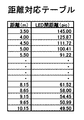
- the calculation means When photographing a target optically enlarged by a telephoto lens, the calculation means is provided with a distance correspondence table that shows the correspondence between the distance from the gun to the target and the light spot interval of two different infrared light emitting means in advance.
- the calculation means can calculate the distance from the gun to the target with reference to the distance table with high accuracy and speed. In particular, when the distance between the gun and the target is 10 m or less, it is preferable to calculate using a distance correspondence table.
- the calculation means is described as being provided in a data processing device different from the gun.
- the calculation means may be configured by a microcomputer and incorporated in the gun. In this case, since only the calculation results such as the distance from the gun to the target and the landing position need be sent from the gun to the display means, the transmission load can be reduced.
- the gun (10) includes an imaging means (24) in the barrel (11) for imaging a target equipped with an infrared light emitting means (3) through a visible light cut filter (23), and further triggers.
- the switch (25) that operates in conjunction with the movement of (14), and the landing position on the target based on the light spot position of the infrared light emitting means in the image data acquired by the imaging means when the switch operates.
- the gun includes a memory for storing a threshold value for binarizing the image acquired by the imaging unit, and the unit for generating transmission data outputs the image binarized based on the threshold value. It is good to generate as transmission data.
- the data processing device (50) is a target image data including two or more infrared light emitting means (3), and is obtained from the image data acquired by the imaging means (24) in the gun (10).
- the light spot position of each of the infrared light emitting means is detected, and the distance from the gun to the target and the landing position on the target are calculated based on the light spot position.
- a shooting competition and training can be performed safely and inexpensively. It can also be used as a shooting toy or shooting game.
- infrared light emitting means for the target and shooting through a visible light cut filter that transmits only infrared light on the gun side it becomes possible to correctly detect the position of the infrared light emitting means by eliminating the influence of ambient light,
- the landing position can be calculated with high accuracy.
- FIG. 1 is an overall configuration diagram of a shooting system 1 according to an embodiment of the present invention. It is explanatory drawing of LED arrangement
- FIG. 4 is a detailed functional block diagram of the imaging unit and transmission control unit of FIG. 3. It is explanatory drawing of the image data processed by the calculating means 51 of FIG. It is explanatory drawing of the search range in image data. It is explanatory drawing of the distance corresponding
- FIG.11 (a) is the state image
- FIG.11 (b) is explanatory drawing showing the state image
- Fig.13 (a) represents the state image
- FIG.13 (b) represented the state image
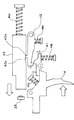
- FIG. 4 is an explanatory diagram of a configuration example of the launching mechanism of FIG. FIG.
- FIG. 5 is an explanatory diagram of another configuration example of the launching mechanism of FIG. It is explanatory drawing of the calculation process of the height correction of the calculating means. It is a whole block diagram of the shooting system 1 by another Example. It is a functional block diagram of the gun by other examples.
- the shooting system 1 schematically includes a target 2 equipped with a plurality of infrared LEDs (infrared light emitting means) 3, a gun 10 (see FIG. 3) equipped with an imaging means (camera) 24, and an imaging means 24.
- the data processing device 50 is configured to acquire an image taken in step (a) and calculate a landing position.
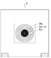
- FIG. 1 An example of the arrangement of the infrared LED 3 mounted on the target 2 on the target is shown in FIG.
- the infrared LED 3a is attached to the center of the target having a concentric score area, and two infrared LEDs 3b and 3c are attached on a straight line passing through the center of the target.
- the infrared LEDs 3b and 3c are preferably arranged at equal distances on a straight line across the target infrared LED 3a.
- the light emitting portion of each infrared LED is exposed from the hole provided at the position of the target infrared LED 3 (3a to 3c), and can be imaged from the imaging means 24 of the gun 10.
- the infrared LEDs 3 (3a to 3c) on the target are positioned on the vertical / horizontal lines so that it can be confirmed that the image is not an inverted image when the target image is viewed on the data processing device. Rather, it is better to place it diagonally.
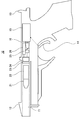
- the gun 10 has an imaging means 24 mounted in the barrel 11 of the gun body, a visible light cut filter 23 is attached to the front side (muzzle side), and a telephoto lens 21 is provided via a lens tube 22. Yes.
- These means 21 to 24 are preferably aligned with the barrel cavity and its central axis.
- the specification of the visible light cut filter 23 can be determined by the specification of the infrared LED 3 on the target 2 side. For example, when an LED having a peak wavelength of 940 nm is employed as the infrared LED on the target side, it is preferable to use a visible light cut filter corresponding to this that cuts a wavelength below 920 nm, IR92.
- the attachment position can be changed variously as necessary.
- the visible light cut filter may be provided in the forefront, or the lens tube may be omitted.
- the gun 10 further includes a transmission control unit 26 that detects the operation of the switch 25 and transmits the image data acquired by the imaging unit 24.
- the imaging unit 24 includes an imaging element 24a and an image processing unit 24b that converts the captured image into image data of a predetermined format.
- the transmission control unit 26 includes a transmission processing unit that periodically acquires image data from the imaging unit 24 and stores the image data in a memory, and a transmission unit that transmits the image data in the memory included in the transmission processing unit to the data processing device 50. Yes.
- a CCD element or a CMOS element can be used as the imaging element 24a, and a captured image having a predetermined size such as a VGA size (640 ⁇ 480 pixels) is transferred to the image processing unit 24b.
- the image processing unit 24 b generates compressed data from the captured image, for example, in the format of motion JPEG, and inputs this to the transmission control means 26.
- the transmission processing unit 32 of the transmission control unit 26 sequentially writes the image data from the image processing unit 24 b into the memory 33. This memory may be overwritten sequentially when a certain amount of data is written using, for example, a circular memory.
- the transmission processing unit 32 receives an operation signal of the switch 25, detects that the switch 25 is turned on, and is stored in the memory by wireless communication such as Wi-Fi (registered trademark, the same applies hereinafter) via the transmission unit 34.
- Wi-Fi registered trademark, the same applies hereinafter
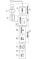
- the data processing device 50 includes a receiving unit 53 that receives image data transmitted from the transmission control unit 26 of the gun 10, and a distance from the gun to the target and landing on the target using the received image data.
- a calculation means 51 for calculating the position and the like and a display means 52 for displaying the calculation result are provided.
- Each means 51 to 53 is connected via a communication means such as a LAN or USB.
- the data processing device 50 can be realized using a general personal computer equipped with a wireless communication function such as Wi-Fi.
- a shooter who is a user of the system 1 aims at the target 2 with the gun 10.
- the transmission control means 26 mounted on the gun 10 always fetches target image data from the imaging means 24 periodically and writes it in the memory 33.
- the trigger (trigger) 14 of the gun 10 in this state, the bullet (bullet) 16 fired by the firing mechanism 15 presses the switch 25 to turn it on.
- the transmission processing unit 32 of the transmission control unit 26 transmits the latest image data stored in the memory 33 via the transmission unit 34.
- the firing mechanism 15 is based on the prior art, and for example, there is one that fires the bullet 16 by the force of air (air), but other methods can also be used.
- each means 41 to 47 constitutes a conventional firing mechanism 15.
- the other ends of the springs 44a to 44d are fixed to the gun body.
- the method of pushing the switch 25 using the conventional launch mechanism 15 is not limited to that shown in FIG. 14.
- the button of the switch 25 may be pushed directly by the striker 43.
- the calculation means 51 detects the position of the infrared LED on the target from the image data, and sets the interval between the infrared LEDs. Based on the distance from the gun to the target and the landing position on the target, the calculation result is output to the display means 52.
- a channel may be assigned to each gun 10, and the calculation means 51 may perform processing in units of groups (channel groups) to which the same channel is assigned, or may perform processing independently for each gun.
- LED light spot search method In the gun 10, the target is magnified and photographed by the telephoto lens 21, and the calculation means 51 of the data processing device 50 limits the search range of the LED light spot in the captured image to a predetermined range and determines the LED. Perform detection processing. As a result, it is possible to detect the LED light spot with high accuracy by eliminating the influence of ambient light. What is important at this time is that the plurality of LEDs on the target to be subjected to the detection processing are imaged at the same exposure timing, that is, at the same exposure timing. This is because the LED on the target is slightly shifted in position in the image for each exposure process due to the influence of ambient light (for example, flickering of illumination or natural light). By detecting the position of each LED using images captured at the same exposure timing, it is possible to detect the position with high accuracy by eliminating the influence of ambient light.
- the image in FIG. 5 is an image taken through a telephoto lens, but there is no recognition point other than the original LED on the target surface.
- the light spot of the LED is determined when the vertical / horizontal difference of the light spot is within a certain value (for example, 16 pixels).
- a condition that the light spot radius is an LED light spot may be used. This makes it possible to accurately detect the LED from the captured image that has been binarized in particular.
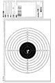
- the outermost frame G of the target concentric circle (usually a place where the score is 0 point, see FIG. 6) is at the center of the screen, three LED light spots for distance measurement are set. Make sure it is just within the range. For the entire circumference of the circular target, the size of the mount of the target 2 is determined in advance by defining the range in this way.
- FIG. 6 is an example of image data processed by the computing means 51.
- the frame F corresponds to the search range in the mount 2a of the target 2.
- the frame F is within the range of the target mount.
- the distance correspondence table shown in FIG. 7 showing the correspondence between the gun-target distance (m) and the number of pixels between the light spots of the two-end LEDs 3b and 3c (inter-LED distance (pic)).
- the distance between the guns and the target is determined by referring to this distance correspondence table from the distance between the light spots of the two-end LEDs extracted from the image data in advance in the calculation means 51.
- a calculation example is shown below.
- the distance to the target among the three LED light spots, the outer two are the LED light spots for distance calculation and the central one LED light spot is the center of the target image. Number). Thereafter, the distance (d) is calculated from the distance correspondence table.
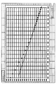
- the accuracy becomes worse if the distance (number of pixels) between the LED light points is simply multiplied by a coefficient. This is because, as shown in FIG. 8, the relationship between the distance between the LED light spots and the distance from the gun (imaging means) to the target is not linear. However, according to the method described above, the distance from the gun to the target can be accurately calculated regardless of the distance.
- the distance between the light spots of the infrared LEDs 3b and 3c at both ends the distance between the light spots of the center infrared LED 3a and the infrared LED (3b or 3c) at one end may be used. good.
- the computing means 51 first calculates the distance between two outer LEDs at a standard distance (for example, 10 m) from the distance relationship table, and calculates the size per pixel.
- the landing point on the target image calculates the X and Y coordinates, and a symbol (for example, ⁇ ) indicating the landing position is displayed on the coordinates. Then, the length of the hypotenuse is obtained from the X and Y dimensions using a trigonometric function, and the score is determined.
- FIG. 9 shows an example of a result display screen output to the display unit 52. In this figure, the landing position is displayed as a symbol on the target displayed graphically on the display screen, and the latest landing display is displayed by color. Infrared LED is not displayed.
- the current information field displays the distance from the gun to the target in real time.
- the history column displays the score history and the total score, and the history column information is cleared by selecting the history deletion button in the bottom column.
- the trajectory varies depending on the distance from the gun 10 to the target 2. For this reason, it is preferable to calculate the landing position in consideration of the amount of bullet fall. Furthermore, according to the present embodiment, the positions of the sighting devices (front site 12 and rear site 13 shown in FIGS. 3 and 16) and the imaging means 24 are shifted in the height direction. For this reason, it is necessary to readjust the sighting device when the distance is different.
- the height direction is corrected according to the distance. This correction method will be described below.
- the correction value H in the case of using the aim matched at the position P for shooting at the position Q is obtained by the following equation.
- H (ML) ⁇ S / M
- M is the distance from the gun (imaging means) to the position P
- L is the distance from the gun (imaging means) to the position Q
- S is the captured image (line connecting the front site and the rear site) ( This is the distance to the center of the image sensor.
- the distance M can be set by the user in the calculation means 51 of the data processing apparatus 50, and the distance L between the gun and the target calculated by the calculation means 51 can be used as the distance L.
- the length S may be set by the user according to the type of gun used, or may be registered in the data processing apparatus in advance.
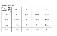
- correction value H can be obtained by using the correction table illustrated in FIG. 10 instead of the above calculation.
- This height correction table is registered in advance in the calculation means 51, the rows of the correction table are set distance values registered in the calculation means 51 by the user, and the columns are calculated by the calculation means 51 after the user's shooting. The calculated distance between the gun and the target is shown.
- the user uses a gun with a sighting target at a distance of 10 m at a distance of another distance (for example, 5 m)
- the user sets 10 m in the calculation means 51.
- the calculation means 51 determines that the distance between the gun and the target is 5 m from the LED light spot interval of the image data sent after the user's shooting, the calculation means 51 accesses the height correction table and The intersection value (5 mm) of 10 m and column 5 m is extracted, and the extracted value is added as a correction value to the Y coordinate Y (YLED) in the captured image of the center LED, and the subsequent processing is executed.
- This correction process improves the user's convenience because it is not necessary for the user to readjust the sighting device every time in games or training in environments with different distances.
- one infrared LED is provided at the center of the target, and further, two LEDs are arranged on both sides of the center LED on a straight line passing through the center, and the telephoto lens provided in the barrel.
- the target is magnified and imaged by a visible light cut filter and an imaging means.
- the LED light spot is detected by narrowing the search range, so that it is possible to detect the light spot with high accuracy by eliminating the influence of ambient light, and the landing position can be calculated with high accuracy.
- this invention is not limited to said embodiment, It can implement in various deformation
- modified examples will be described.
- Target variation In the present embodiment, three infrared LEDs are provided on the target. However, where the influence of ambient light is relatively small, it is possible to realize it with at least two infrared LEDs. In this case, for example, the infrared LED at the center of the target is removed, and only the infrared LEDs on both sides provided at the same distance from the center are used. And what is necessary is just to make the middle point of both LED light spots the center of a target.
- the infrared LEDs 3b and 3c at both ends can be made inconspicuous by placing them in a black circle, but if this is difficult due to conditions such as the resolution of the captured image, it will be on the circumference of one of the concentric circles. It is preferable to arrange.
- the firing mechanism 15 moves the bullet (bullet) 16 and pushes the switch 25, or the striker 43 of the firing mechanism 15 pushes the switch 25 directly.
- the switch 25 is operated using the conventional launch mechanism 15 and is not limited to the above-described embodiment.
- the striker 43 shown in FIG. When the trigger 14 is pulled, the switch 25 may be pushed by a firing pin that moves away from the shear (reverse hook) and moves forward with a spring.
- the captured image is always stored in the memory 33 on the gun 10 side, and the latest image stored in the memory 33 is transmitted when the switch 25 is operated.
- power may be supplied to the imaging unit 24, and a captured image may be acquired by operating a shutter of the imaging unit 24, and the captured image may be transmitted.
- the captured image is converted into motion JPEG and transmitted, but only the brightness value (Y value) of the captured image may be transmitted instead of motion JPEG.
- the threshold value for black and white determination may be stored in the memory of the gun 10 and a black and white binarized image may be compressed and transmitted. Thereby, the amount of data transmission can be reduced and the response time can be further improved.
- wireless communication by Wi-Fi is used between the gun 10 and the data processing device 50, but other communication means such as Bluetooth (registered trademark) may be used.
- FIG. 1 (Modification of system configuration)
- image data sent from a plurality of guns 10 is received by a receiving unit 53, and data processing is performed by one or more calculation units 51 in accordance with the calculation load.
- a data processing device 50 having a receiving unit 53, a calculating unit 51, and a display unit 52 may be assigned to each target / gun pair.
- each calculation means 51 is connected by a LAN 55 so that a competition result can be seen on a personal computer (PC) 55 for the athlete.
- PC personal computer
- the operation of the switch is detected to detect the light spot position of each infrared LED from the image data acquired by the imaging means 24, and from the gun to the target based on the light spot position.
- the calculation means 51 for calculating the distance and the landing position on the target may be provided on the gun 10 side, and the calculation result may be sent to the display means 52 by wire or wirelessly and displayed.
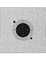
- Example 11A is an image taken outdoors. It can be seen that the three light spots of the LED are correctly detected. The background of the target is reflected by the light with a wavelength of 920 nm or more contained in sunlight. In order to cut this background, it is effective to limit the LED light spot search range to the target score frame.
- the image in FIG. 11B is an image taken by bringing the same prototype environment as in FIG. Since indoors (indoors) are less affected by light rays of 920 nm or more due to sunlight, the images are darker than in FIG. Further, it was found that the light spot appears larger than the outdoors (FIG. 11A) by the brightness adjustment function of the image pickup means 24. However, if the process of determining the center of each light spot of the three LED groups is performed, there is no problem even if the light spot becomes larger as long as the light spot does not stick.
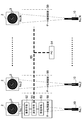
- FIG. 12 shows a target for a rifle using a chip type LED having a peak wavelength of 950 nm as an infrared LED. Since the target is small, the LEDs at both ends are arranged outside the concentric circles.
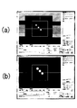
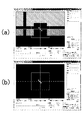
- FIG. 13 is an image of a target imaged by a rifle using an IR92 visible light cut filter.
- FIG. 13A shows an image taken outdoors
- FIG. 13B shows an image taken indoors.
- the entire screen becomes bright due to the near infrared rays contained in the sun rays, and the light spot of the LED becomes smaller than that of the indoor due to the brightness adjustment function of the imaging means.
- the present invention is not limited to the above-described embodiment, and can be implemented with various modifications without departing from the scope of the invention.
- the gun 10 and the data processing device 50 each have a calculation function
- the functions can be appropriately divided.
- the gun 10 and the data processing device 50 are connected by wireless communication, the above arithmetic processing may be divided into functions from the viewpoint of reducing transmission load and optimizing response performance.
- the present invention can be used for a practical shooting system. Since the landing position can be determined with extremely high accuracy, a shooting competition can be performed without using an actual bullet. Also, the same level of training is possible as shooting using live ammunition.
- the present invention can be used for shooting games. Since an infrared LED is used in place of the laser, and the landing position can be determined with high accuracy with a resolution comparable to that of a commercially available camera, it can be provided as an inexpensive and safe shooting game.
Landscapes
- Engineering & Computer Science (AREA)
- General Engineering & Computer Science (AREA)
- Radar, Positioning & Navigation (AREA)
- Physics & Mathematics (AREA)
- Theoretical Computer Science (AREA)
- Business, Economics & Management (AREA)
- Multimedia (AREA)
- Educational Administration (AREA)
- Educational Technology (AREA)
- General Physics & Mathematics (AREA)
- Electromagnetism (AREA)
- Remote Sensing (AREA)
- Aiming, Guidance, Guns With A Light Source, Armor, Camouflage, And Targets (AREA)
Priority Applications (2)
| Application Number | Priority Date | Filing Date | Title |
|---|---|---|---|
| DE112015001226.5T DE112015001226T5 (de) | 2014-03-13 | 2015-03-13 | Schießsystem, Schusswaffe und Datenverarbeitungsvorrichtung |
| US15/125,722 US20170001101A1 (en) | 2014-03-13 | 2015-03-13 | Shooting system, gun, and data processing device |
Applications Claiming Priority (2)
| Application Number | Priority Date | Filing Date | Title |
|---|---|---|---|
| JP2014050644 | 2014-03-13 | ||
| JP2014-050644 | 2014-03-13 |
Publications (1)
| Publication Number | Publication Date |
|---|---|
| WO2015137473A1 true WO2015137473A1 (ja) | 2015-09-17 |
Family
ID=54071910
Family Applications (1)
| Application Number | Title | Priority Date | Filing Date |
|---|---|---|---|
| PCT/JP2015/057393 Ceased WO2015137473A1 (ja) | 2014-03-13 | 2015-03-13 | 射撃システム、銃、及びデータ処理装置 |
Country Status (5)
| Country | Link |
|---|---|
| US (1) | US20170001101A1 (enExample) |
| JP (2) | JP6019283B2 (enExample) |
| DE (1) | DE112015001226T5 (enExample) |
| TW (1) | TW201600826A (enExample) |
| WO (1) | WO2015137473A1 (enExample) |
Cited By (2)
| Publication number | Priority date | Publication date | Assignee | Title |
|---|---|---|---|---|
| CN105371709A (zh) * | 2015-12-11 | 2016-03-02 | 王光树 | 一种红外弹 |
| CN105371712A (zh) * | 2015-12-11 | 2016-03-02 | 王光树 | 一种弹药的触发装置 |
Families Citing this family (4)
| Publication number | Priority date | Publication date | Assignee | Title |
|---|---|---|---|---|
| CN108211335B (zh) * | 2018-01-19 | 2023-12-05 | 南京先进激光技术研究院 | 一种激光模拟对战系统及击中判断方法 |
| CN111150994B (zh) * | 2018-11-07 | 2024-10-25 | 千寻位置网络有限公司 | 仿真武器装备的射击评估方法及装置、服务终端、存储器 |
| CN112870664B (zh) * | 2021-01-07 | 2022-03-25 | 深圳清华大学研究院 | 可见光弹射击打靶装置 |
| CN116625256A (zh) * | 2022-09-26 | 2023-08-22 | 汉王科技股份有限公司 | 打靶设备的校准方法、装置,以及打靶设备 |
Citations (4)
| Publication number | Priority date | Publication date | Assignee | Title |
|---|---|---|---|---|
| JP2004286399A (ja) * | 2003-03-25 | 2004-10-14 | Japan Radio Co Ltd | 照準位置検出システム |
| JP3868633B2 (ja) * | 1998-08-24 | 2007-01-17 | Smk株式会社 | 光位置検出方式 |
| US20090081619A1 (en) * | 2006-03-15 | 2009-03-26 | Israel Aircraft Industries Ltd. | Combat training system and method |
| US20130130205A1 (en) * | 2011-11-18 | 2013-05-23 | Surefire, Llc | Dynamic targeting and training system |
Family Cites Families (15)
| Publication number | Priority date | Publication date | Assignee | Title |
|---|---|---|---|---|
| JP3422383B2 (ja) * | 1994-09-05 | 2003-06-30 | 株式会社タイトー | 射撃ゲーム装置におけるビデオ画面とガンの相対位置を検出する方法及び装置 |
| US5929444A (en) * | 1995-01-31 | 1999-07-27 | Hewlett-Packard Company | Aiming device using radiated energy |
| JP2681454B2 (ja) * | 1995-02-21 | 1997-11-26 | コナミ株式会社 | 射的ゲーム装置 |
| JPH11305935A (ja) * | 1998-04-24 | 1999-11-05 | Image Tec Kk | 位置検出システム |
| JP2002318096A (ja) * | 2001-04-18 | 2002-10-31 | Koto Denshi Kk | 国際射撃競技用高性能光線銃の電子標的システム |
| JP2004333122A (ja) * | 2002-03-05 | 2004-11-25 | Nec Personal Products Co Ltd | 標的装置 |
| JP4557734B2 (ja) * | 2005-01-31 | 2010-10-06 | 株式会社野村総合研究所 | 射撃訓練システム |
| JP3975215B2 (ja) * | 2005-01-31 | 2007-09-12 | 株式会社野村総合研究所 | 射撃訓練システム |
| JP5506129B2 (ja) * | 2006-05-08 | 2014-05-28 | 任天堂株式会社 | ゲームプログラム、ゲーム装置、ゲームシステムおよびゲーム処理方法 |
| JP4861855B2 (ja) * | 2007-02-15 | 2012-01-25 | 株式会社バンダイナムコゲームス | 指示位置演算システム、指示体及びゲームシステム |
| US20100178967A1 (en) * | 2009-01-10 | 2010-07-15 | Chiu-Hao Cheng | Shooting game processing method |
| JP5554010B2 (ja) * | 2009-05-01 | 2014-07-23 | 株式会社タイトー | 射撃ゲーム装置 |
| JP5588742B2 (ja) * | 2010-05-25 | 2014-09-10 | 株式会社タイトー | 位置指示装置 |
| JP5637589B2 (ja) * | 2010-06-30 | 2014-12-10 | 株式会社日立国際電気 | 射撃訓練装置 |
| JP2012113494A (ja) * | 2010-11-24 | 2012-06-14 | Sas Kk | 指示位置検出装置および指示位置検出方法 |
-
2015
- 2015-03-13 WO PCT/JP2015/057393 patent/WO2015137473A1/ja not_active Ceased
- 2015-03-13 TW TW104108109A patent/TW201600826A/zh unknown
- 2015-03-13 DE DE112015001226.5T patent/DE112015001226T5/de not_active Withdrawn
- 2015-03-13 US US15/125,722 patent/US20170001101A1/en not_active Abandoned
- 2015-03-13 JP JP2015050317A patent/JP6019283B2/ja active Active
-
2016
- 2016-04-18 JP JP2016083250A patent/JP2016166731A/ja active Pending
Patent Citations (4)
| Publication number | Priority date | Publication date | Assignee | Title |
|---|---|---|---|---|
| JP3868633B2 (ja) * | 1998-08-24 | 2007-01-17 | Smk株式会社 | 光位置検出方式 |
| JP2004286399A (ja) * | 2003-03-25 | 2004-10-14 | Japan Radio Co Ltd | 照準位置検出システム |
| US20090081619A1 (en) * | 2006-03-15 | 2009-03-26 | Israel Aircraft Industries Ltd. | Combat training system and method |
| US20130130205A1 (en) * | 2011-11-18 | 2013-05-23 | Surefire, Llc | Dynamic targeting and training system |
Cited By (2)
| Publication number | Priority date | Publication date | Assignee | Title |
|---|---|---|---|---|
| CN105371709A (zh) * | 2015-12-11 | 2016-03-02 | 王光树 | 一种红外弹 |
| CN105371712A (zh) * | 2015-12-11 | 2016-03-02 | 王光树 | 一种弹药的触发装置 |
Also Published As
| Publication number | Publication date |
|---|---|
| US20170001101A1 (en) | 2017-01-05 |
| TW201600826A (zh) | 2016-01-01 |
| DE112015001226T5 (de) | 2016-12-15 |
| JP2016166731A (ja) | 2016-09-15 |
| JP6019283B2 (ja) | 2016-11-02 |
| JP2015187537A (ja) | 2015-10-29 |
Similar Documents
| Publication | Publication Date | Title |
|---|---|---|
| JP6019283B2 (ja) | 射撃システム及びデータ処理装置 | |
| US10274287B2 (en) | System and method for marksmanship training | |
| US10234240B2 (en) | System and method for marksmanship training | |
| US8851994B2 (en) | Game device, game control method, and game control program adapted to control game by using position and posture of input device | |
| US20160180532A1 (en) | System for identifying a position of impact of a weapon shot on a target | |
| JP6534779B2 (ja) | レーザー光射撃システム | |
| EA031066B1 (ru) | Система прицеливания огнестрельного оружия (варианты) и способ управления работой огнестрельного оружия | |
| CN109341427A (zh) | 一种激光枪靶系统 | |
| US20170321987A1 (en) | Simulated firearm with target accuracy detection, and related methods and systems | |
| US20210372738A1 (en) | Device and method for shot analysis | |
| CN113008076A (zh) | 影像枪、影像打靶系统、影像打靶方法及存储介质 | |
| JP2015187537A5 (enExample) | ||
| SE0402472L (sv) | Anordning för automatisk inställning av optiskt sikte för skjutvapen | |
| US12305961B2 (en) | Device and method for shot analysis | |
| KR101912754B1 (ko) | 사격용 표적 표시 시스템 | |
| JP2021032425A (ja) | 射撃訓練システム | |
| KR102151340B1 (ko) | 비비탄용 사격 시스템의 탄착점 검출 방법 | |
| KR20140112117A (ko) | 무선 실내 사격 시뮬레이션 시스템 | |
| JP4614783B2 (ja) | 射撃訓練システム | |
| KR102011765B1 (ko) | 목표물의 조준 방법 및 장치 | |
| KR101332741B1 (ko) | 아케이드 건 인터렉션 시스템 | |
| CN114405007A (zh) | 模拟射击模型建立方法、模拟射击方法、装置及存储介质 | |
| KR20090107463A (ko) | 실 방향 동적 사격 훈련 시스템 | |
| KR20210155931A (ko) | 이동 목표물 조준 방법 및 조준 장치 | |
| KR102548388B1 (ko) | 레이저 사격 시스템 |
Legal Events
| Date | Code | Title | Description |
|---|---|---|---|
| 121 | Ep: the epo has been informed by wipo that ep was designated in this application |
Ref document number: 15762294 Country of ref document: EP Kind code of ref document: A1 |
|
| WWE | Wipo information: entry into national phase |
Ref document number: 15125722 Country of ref document: US Ref document number: 112015001226 Country of ref document: DE |
|
| 122 | Ep: pct application non-entry in european phase |
Ref document number: 15762294 Country of ref document: EP Kind code of ref document: A1 |