WO2015137456A1 - 内燃機関 - Google Patents
内燃機関 Download PDFInfo
- Publication number
- WO2015137456A1 WO2015137456A1 PCT/JP2015/057330 JP2015057330W WO2015137456A1 WO 2015137456 A1 WO2015137456 A1 WO 2015137456A1 JP 2015057330 W JP2015057330 W JP 2015057330W WO 2015137456 A1 WO2015137456 A1 WO 2015137456A1
- Authority
- WO
- WIPO (PCT)
- Prior art keywords
- clutch
- compression ratio
- torque
- output shaft
- reverse input
- Prior art date
- Legal status (The legal status is an assumption and is not a legal conclusion. Google has not performed a legal analysis and makes no representation as to the accuracy of the status listed.)
- Ceased
Links
Images












Classifications
-
- F—MECHANICAL ENGINEERING; LIGHTING; HEATING; WEAPONS; BLASTING
- F02—COMBUSTION ENGINES; HOT-GAS OR COMBUSTION-PRODUCT ENGINE PLANTS
- F02D—CONTROLLING COMBUSTION ENGINES
- F02D15/00—Varying compression ratio
- F02D15/04—Varying compression ratio by alteration of volume of compression space without changing piston stroke
-
- F—MECHANICAL ENGINEERING; LIGHTING; HEATING; WEAPONS; BLASTING
- F02—COMBUSTION ENGINES; HOT-GAS OR COMBUSTION-PRODUCT ENGINE PLANTS
- F02B—INTERNAL-COMBUSTION PISTON ENGINES; COMBUSTION ENGINES IN GENERAL
- F02B75/00—Other engines
- F02B75/04—Engines with variable distances between pistons at top dead-centre positions and cylinder heads
- F02B75/041—Engines with variable distances between pistons at top dead-centre positions and cylinder heads by means of cylinder or cylinderhead positioning
-
- F—MECHANICAL ENGINEERING; LIGHTING; HEATING; WEAPONS; BLASTING
- F16—ENGINEERING ELEMENTS AND UNITS; GENERAL MEASURES FOR PRODUCING AND MAINTAINING EFFECTIVE FUNCTIONING OF MACHINES OR INSTALLATIONS; THERMAL INSULATION IN GENERAL
- F16D—COUPLINGS FOR TRANSMITTING ROTATION; CLUTCHES; BRAKES
- F16D41/00—Freewheels or freewheel clutches
- F16D41/06—Freewheels or freewheel clutches with intermediate wedging coupling members between an inner and an outer surface
- F16D41/064—Freewheels or freewheel clutches with intermediate wedging coupling members between an inner and an outer surface the intermediate members wedging by rolling and having a circular cross-section, e.g. balls
- F16D41/066—Freewheels or freewheel clutches with intermediate wedging coupling members between an inner and an outer surface the intermediate members wedging by rolling and having a circular cross-section, e.g. balls all members having the same size and only one of the two surfaces being cylindrical
-
- F—MECHANICAL ENGINEERING; LIGHTING; HEATING; WEAPONS; BLASTING
- F16—ENGINEERING ELEMENTS AND UNITS; GENERAL MEASURES FOR PRODUCING AND MAINTAINING EFFECTIVE FUNCTIONING OF MACHINES OR INSTALLATIONS; THERMAL INSULATION IN GENERAL
- F16D—COUPLINGS FOR TRANSMITTING ROTATION; CLUTCHES; BRAKES
- F16D41/00—Freewheels or freewheel clutches
- F16D41/06—Freewheels or freewheel clutches with intermediate wedging coupling members between an inner and an outer surface
- F16D41/08—Freewheels or freewheel clutches with intermediate wedging coupling members between an inner and an outer surface with provision for altering the freewheeling action
- F16D41/086—Freewheels or freewheel clutches with intermediate wedging coupling members between an inner and an outer surface with provision for altering the freewheeling action the intermediate members being of circular cross-section and wedging by rolling
- F16D41/088—Freewheels or freewheel clutches with intermediate wedging coupling members between an inner and an outer surface with provision for altering the freewheeling action the intermediate members being of circular cross-section and wedging by rolling the intermediate members being of only one size and wedging by a movement not having an axial component, between inner and outer races, one of which is cylindrical
-
- F—MECHANICAL ENGINEERING; LIGHTING; HEATING; WEAPONS; BLASTING
- F16—ENGINEERING ELEMENTS AND UNITS; GENERAL MEASURES FOR PRODUCING AND MAINTAINING EFFECTIVE FUNCTIONING OF MACHINES OR INSTALLATIONS; THERMAL INSULATION IN GENERAL
- F16D—COUPLINGS FOR TRANSMITTING ROTATION; CLUTCHES; BRAKES
- F16D41/00—Freewheels or freewheel clutches
- F16D41/06—Freewheels or freewheel clutches with intermediate wedging coupling members between an inner and an outer surface
- F16D41/08—Freewheels or freewheel clutches with intermediate wedging coupling members between an inner and an outer surface with provision for altering the freewheeling action
- F16D41/10—Freewheels or freewheel clutches with intermediate wedging coupling members between an inner and an outer surface with provision for altering the freewheeling action with self-actuated reversing
- F16D41/105—Freewheels or freewheel clutches with intermediate wedging coupling members between an inner and an outer surface with provision for altering the freewheeling action with self-actuated reversing the intermediate members being of circular cross-section, of only one size and wedging by rolling movement not having an axial component between inner and outer races, one of which is cylindrical
-
- F—MECHANICAL ENGINEERING; LIGHTING; HEATING; WEAPONS; BLASTING
- F16—ENGINEERING ELEMENTS AND UNITS; GENERAL MEASURES FOR PRODUCING AND MAINTAINING EFFECTIVE FUNCTIONING OF MACHINES OR INSTALLATIONS; THERMAL INSULATION IN GENERAL
- F16D—COUPLINGS FOR TRANSMITTING ROTATION; CLUTCHES; BRAKES
- F16D48/00—External control of clutches
- F16D48/06—Control by electric or electronic means, e.g. of fluid pressure
-
- F—MECHANICAL ENGINEERING; LIGHTING; HEATING; WEAPONS; BLASTING
- F16—ENGINEERING ELEMENTS AND UNITS; GENERAL MEASURES FOR PRODUCING AND MAINTAINING EFFECTIVE FUNCTIONING OF MACHINES OR INSTALLATIONS; THERMAL INSULATION IN GENERAL
- F16D—COUPLINGS FOR TRANSMITTING ROTATION; CLUTCHES; BRAKES
- F16D2500/00—External control of clutches by electric or electronic means
- F16D2500/30—Signal inputs
- F16D2500/308—Signal inputs from the transmission
- F16D2500/3082—Signal inputs from the transmission from the output shaft
- F16D2500/30822—Torque of the output shaft
-
- F—MECHANICAL ENGINEERING; LIGHTING; HEATING; WEAPONS; BLASTING
- F16—ENGINEERING ELEMENTS AND UNITS; GENERAL MEASURES FOR PRODUCING AND MAINTAINING EFFECTIVE FUNCTIONING OF MACHINES OR INSTALLATIONS; THERMAL INSULATION IN GENERAL
- F16D—COUPLINGS FOR TRANSMITTING ROTATION; CLUTCHES; BRAKES
- F16D2500/00—External control of clutches by electric or electronic means
- F16D2500/50—Problem to be solved by the control system
- F16D2500/502—Relating the clutch
- F16D2500/50227—Control of clutch to control engine
-
- F—MECHANICAL ENGINEERING; LIGHTING; HEATING; WEAPONS; BLASTING
- F16—ENGINEERING ELEMENTS AND UNITS; GENERAL MEASURES FOR PRODUCING AND MAINTAINING EFFECTIVE FUNCTIONING OF MACHINES OR INSTALLATIONS; THERMAL INSULATION IN GENERAL
- F16D—COUPLINGS FOR TRANSMITTING ROTATION; CLUTCHES; BRAKES
- F16D2500/00—External control of clutches by electric or electronic means
- F16D2500/70—Details about the implementation of the control system
- F16D2500/704—Output parameters from the control unit; Target parameters to be controlled
- F16D2500/70452—Engine parameters
-
- F—MECHANICAL ENGINEERING; LIGHTING; HEATING; WEAPONS; BLASTING
- F16—ENGINEERING ELEMENTS AND UNITS; GENERAL MEASURES FOR PRODUCING AND MAINTAINING EFFECTIVE FUNCTIONING OF MACHINES OR INSTALLATIONS; THERMAL INSULATION IN GENERAL
- F16D—COUPLINGS FOR TRANSMITTING ROTATION; CLUTCHES; BRAKES
- F16D2500/00—External control of clutches by electric or electronic means
- F16D2500/70—Details about the implementation of the control system
- F16D2500/704—Output parameters from the control unit; Target parameters to be controlled
- F16D2500/70452—Engine parameters
- F16D2500/70458—Engine torque
-
- F—MECHANICAL ENGINEERING; LIGHTING; HEATING; WEAPONS; BLASTING
- F16—ENGINEERING ELEMENTS AND UNITS; GENERAL MEASURES FOR PRODUCING AND MAINTAINING EFFECTIVE FUNCTIONING OF MACHINES OR INSTALLATIONS; THERMAL INSULATION IN GENERAL
- F16D—COUPLINGS FOR TRANSMITTING ROTATION; CLUTCHES; BRAKES
- F16D2500/00—External control of clutches by electric or electronic means
- F16D2500/70—Details about the implementation of the control system
- F16D2500/704—Output parameters from the control unit; Target parameters to be controlled
- F16D2500/70452—Engine parameters
- F16D2500/70458—Engine torque
- F16D2500/7046—Engine torque change rate
Definitions
- the present invention relates to an internal combustion engine.
- the air / fuel mixture is ignited in a compressed state.
- the compression ratio when the air-fuel mixture is compressed affects the output and fuel consumption of the internal combustion engine.
- the output torque can be increased and the thermal efficiency can be improved.
- abnormal combustion such as knocking occurs when the compression ratio is too high.
- an internal combustion engine having a variable compression ratio mechanism that changes a compression ratio during an operation period is known.
- the variable compression ratio mechanism can change the compression ratio by changing the volume of the combustion chamber when the piston reaches top dead center.
- the in-cylinder pressure increases.
- a force acts on the members constituting the combustion chamber in a direction in which the volume of the combustion chamber increases, and this force also acts on the variable compression ratio mechanism.
- this force may be transmitted to a rotating machine such as a motor that drives a mechanism that changes the volume of the combustion chamber.
- variable compression ratio mechanism is provided with a reverse input blocking clutch that blocks the rotational force due to the in-cylinder pressure so that the rotational force due to the in-cylinder pressure is not transmitted to the output shaft of the rotating machine.
- the reverse input cut-off clutch has a lock function that cuts off the rotational force applied to the output shaft of the rotating machine.
- Japanese Patent Application Laid-Open No. 2005-214088 discloses a variable compression ratio engine that can change the position when the piston reaches top dead center by moving the reciprocating element forward and backward.
- the compression ratio is changed by an actuator mechanism.
- the actuator mechanism includes a ball screw, a rotation transmission system that transmits the rotation of the motor to a nut of the ball screw, and a clutch interposed in the rotation transmission system.
- This publication discloses the use of a reverse input limiting clutch that transmits rotation from an input member to which a motor drive is input to the nut, but blocks transmission of rotation from the nut to the input member. Yes.
- Japanese Patent Application Laid-Open No. 2012-229964 includes a torque diode that prevents the load torque of the output shaft from being transmitted to the input shaft when torque is not transmitted from the input shaft to the output shaft, and releases the locked state of the torque diode.
- An unlocking device is disclosed. In this unlock control device, it is disclosed that the unlock torque is gradually increased when the locked state is not released even if the set unlock torque is continuously applied for a predetermined time.
- the change in the mechanical compression ratio is not limited to the period during which the engine body is being driven, but may be performed while the engine body is stopped.
- the mechanical compression ratio may be changed immediately before starting the engine body in order to detect an abnormality in the variable compression ratio mechanism.
- the mechanical compression ratio may be changed in order to prevent the bearing from sticking by forming an oil film on the surface of the eccentric shaft.
- the rotating machine that drives the input shaft of the reverse input cut-off clutch in order to release the locked state of the reverse input cut-off clutch in all states that occur during both the operation and the stop period of the engine body. It is conceivable to select a rotating machine with a large output torque. However, when the capacity of the rotating machine is increased, there is a problem that power consumption increases and fuel consumption of the internal combustion engine increases. Moreover, there exists a problem that a rotary machine becomes large sized and the place which arrange
- An object of the present invention is to provide an internal combustion engine that includes a variable compression ratio mechanism including a reverse input cutoff clutch and that can reduce the size of a rotating machine that drives the variable compression ratio mechanism.
- the internal combustion engine of the present invention includes a variable compression ratio mechanism that can change the mechanical compression ratio.
- the variable compression ratio mechanism includes a drive device for changing the volume of the combustion chamber when the piston reaches top dead center, and a control device that controls the drive device.
- the drive device includes a rotating machine and a clutch disposed in a driving force transmission path that transmits the rotational force of the rotating machine.
- the clutch is formed so as to cut off the reverse input torque applied to the output shaft in the rotational direction that lowers the mechanical compression ratio.
- the control device estimates the reverse input torque applied to the output shaft of the clutch, sets a torque gradient output from the rotating machine and a duration for continuing the torque increase based on the reverse input torque, and sets the torque gradient and the duration. Based on this, the clutch is unlocked.
- the clutch includes an input shaft to which the rotational force of the rotating machine is input, an output shaft to which the rotational force is transmitted from the input shaft, and an outer ring that does not move while the clutch is being driven. Between the outer ring and the outer ring, the output shaft and the outer ring form a locking portion for locking the roller, and the clutch has a reverse rotational torque acting on the output shaft that reduces the mechanical compression ratio.
- the controller is configured to block the reverse input torque by locking the roller to the locking portion and locking the output shaft with respect to the outer ring, and the control device controls the input shaft based on the torque gradient and the duration. By rotating the roller, the roller can be separated from the engaging portion and the output shaft can be unlocked.
- the rotating machine includes the electric motor, and the control device controls the torque gradient by changing the duty ratio of the current supplied to the electric motor, and changes the duration of supplying the electric power to the electric motor by continuing the duration. Can be controlled.
- variable compression ratio mechanism includes a lubricating oil supply device that supplies lubricating oil to the clutch, and a temperature detector that detects the temperature of the lubricating oil, and the control device detects the temperature of the lubricating oil, The torque gradient and duration can be controlled based on the temperature of the lubricating oil.
- a storage battery that supplies electric power to the electric motor and a voltage detector that detects an output voltage of the storage battery, the control device detects the output voltage of the storage battery, and the output voltage is determined in advance. If not, the torque gradient and duration can be set based on the voltage drop allowed to release the lock.
- a support structure including a crankcase and a cylinder block supported by the support structure
- the variable compression ratio mechanism is interposed between the support structure and the cylinder block, and has an eccentric shaft.
- the drive device can change the size of the combustion chamber by rotating the shaft to change the relative position of the cylinder block with respect to the support structure.
- the controller includes an urging member that urges the cylinder block in a direction away from the support structure, and the control device reduces the mechanical compression ratio during a period in which the combustion of fuel in the combustion chamber is stopped.
- the torque gradient and duration can be set based on the biasing force of the biasing member.
- the in-cylinder pressure detector for detecting the in-cylinder pressure and the rotational force estimation device for estimating the reverse input torque applied to the output shaft of the clutch are provided, and the control device performs mechanical compression during the operation period of the internal combustion engine.
- the control device performs mechanical compression during the operation period of the internal combustion engine.
- the in-cylinder pressure is detected, and the rotary machine is controlled to start driving the clutch input shaft during the period in which the in-cylinder pressure changes from the maximum point to the minimum point.
- the amplitude of the vibration of the applied reverse input torque is less than a predetermined determination value, the reverse input torque can be estimated and the torque gradient and duration can be set based on the reverse input torque.
- an internal combustion engine that includes a variable compression ratio mechanism including a reverse input cutoff clutch and that can reduce the size of a rotating machine that drives the variable compression ratio mechanism.
- 1 is a schematic overall view of an internal combustion engine in an embodiment. It is a general
- the internal combustion engine according to the embodiment will be described with reference to FIGS.
- a spark ignition type internal combustion engine attached to a vehicle will be described as an example.
- the internal combustion engine in the present embodiment includes a variable compression ratio mechanism that can change the mechanical compression ratio.
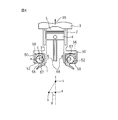
- FIG. 1 is a schematic diagram of an internal combustion engine according to an embodiment.
- the internal combustion engine includes an engine body 90.
- the engine body 90 includes a support structure including the crankcase 1.
- the support structure is formed to support the crankshaft.
- the engine body 90 includes the cylinder block 2 and the cylinder head 3.
- a piston 4 is disposed in a hole formed in the cylinder block 2.
- a spark plug 6 is disposed at the center of the top surface of the combustion chamber 5.
- the space surrounded by the crown surface of the piston 4, the hole of the cylinder block 2, and the cylinder head 3 at the position of the arbitrary piston 4 is referred to as a combustion chamber.
- an in-cylinder pressure sensor 23 is disposed as an in-cylinder pressure detector that detects the pressure in the combustion chamber 5, that is, the in-cylinder pressure.
- the cylinder head 3 is formed with an intake port 8 and an exhaust port 10.
- An intake valve 7 is disposed at the end of the intake port 8.
- the intake valve 7 opens and closes as the intake cam 49 rotates.
- An exhaust valve 9 is disposed at the end of the exhaust port 10.
- the intake port 8 is connected to a surge tank 12 via an intake branch pipe 11.
- a fuel injection valve 13 for injecting fuel into the corresponding intake port 8 is arranged in each intake branch pipe 11.
- the fuel injection valve 13 may be arranged so as to inject fuel directly into each combustion chamber 5 instead of being attached to the intake branch pipe 11.
- the surge tank 12 is connected to an air cleaner 15 via an intake duct 14.
- a throttle valve 17 driven by an actuator 16 is disposed inside the intake duct 14.
- an intake air amount detector 18 using, for example, heat rays is disposed inside the intake duct 14.
- the exhaust port 10 is connected through an exhaust manifold 19 to a catalyst device 20 containing, for example, a three-way catalyst.
- An air-fuel ratio sensor 21 is disposed in the exhaust manifold 19.
- the internal combustion engine in the present embodiment includes a variable compression ratio mechanism A that can change the volume of the combustion chamber 5 when the piston 4 is located at the compression top dead center.
- the variable compression ratio mechanism A is formed so as to change the relative position of the cylinder block 2 with respect to the crankcase 1 in the cylinder axial direction.
- a lift spring 65 as an urging member is disposed between the crankcase 1 and the cylinder block 2.
- the lift spring 65 is formed to urge the cylinder block 2 in a direction away from the crankcase 1.
- the urging member is not limited to this form, and any member that urges the cylinder block in a direction away from the crankcase can be employed.
- a relative position sensor 22 for detecting the relative position of the cylinder block 2 with respect to the crankcase 1 is attached to the crankcase 1 and the cylinder block 2.
- the relative position sensor 22 outputs an output signal indicating a change in the interval between the crankcase 1 and the cylinder block 2.
- a throttle opening sensor 24 for generating an output signal indicating the throttle valve opening is attached to the actuator 16 for driving the throttle valve.
- the control device for the internal combustion engine in the present embodiment includes an electronic control unit 30.
- Electronic control unit 30 in the present embodiment includes a digital computer.
- the digital computer includes a ROM (Read Only Memory) 32, a RAM (Random Access Memory) 33, a CPU (Microprocessor) 34, an input port 35 and an output port 36 connected to each other by a bidirectional bus 31.
- the output signals of the intake air amount detector 18, the air-fuel ratio sensor 21, the relative position sensor 22, the in-cylinder pressure sensor 23, and the throttle opening sensor 24 are input to the input port 35 via corresponding AD converters 37.
- a load sensor 41 that generates an output voltage proportional to the amount of depression of the accelerator pedal 40 is connected to the accelerator pedal 40.
- the output voltage of the load sensor 41 is input to the input port 35 via the corresponding AD converter 37.
- the required load can be detected from the output of the load sensor 41.
- the input port 35 is connected to a crank angle sensor 42 that generates an output pulse every time the crankshaft rotates, for example, 30 °. From the output of the crank angle sensor 42, the crank angle and the engine speed can be detected.
- the output port 36 is connected to the ignition plug 6, the fuel injection valve 13, the actuator 16 for driving the throttle valve, and the variable compression ratio mechanism A through a corresponding drive circuit 38. These devices are controlled by the electronic control unit 30.
- FIG. 2 is an exploded perspective view of the variable compression ratio mechanism in the present embodiment.
- FIG. 3 shows a first schematic cross-sectional view of the variable compression ratio mechanism in the present embodiment.
- a plurality of protrusions 50 spaced from each other are formed below both side walls of cylinder block 2.
- Each protrusion 50 is formed with a cam insertion hole 51 having a circular cross section.
- the upper wall of the crankcase 1 is formed with a plurality of protrusions 52 that are fitted between the protrusions 50 at intervals.
- These protrusions 52 are also formed with cam insertion holes 53 having a circular cross section.
- the variable compression ratio mechanism in the present embodiment includes camshafts 54 and 55 as shafts including an eccentric shaft.
- the camshafts 54 and 55 are interposed between the crankcase 1 and the cylinder block 2.
- circular cams 58 that are rotatably inserted into the respective cam insertion holes 53 are arranged. These circular cams 58 are coaxial with the rotational axes of the camshafts 54 and 55.
- eccentric shafts 57 arranged eccentrically with respect to the rotational axes of the respective cam shafts 54, 55 extend as shown in FIG.
- Another circular cam 56 is eccentrically attached to the eccentric shaft 57 so as to be rotatable. As shown in FIG.
- the circular cams 56 are disposed on both sides of each circular cam 58. These circular cams 56 are rotatably inserted into the corresponding cam insertion holes 51.
- the cylinder block 2 is supported by the crankcase 1 via camshafts 54 and 55 including an eccentric shaft 57.
- FIG. 4 shows a second schematic cross-sectional view of the variable compression ratio mechanism in the present embodiment.
- FIG. 5 shows a third schematic cross-sectional view of the variable compression ratio mechanism in the present embodiment.
- 3 to 5 are cross-sectional views illustrating the function of the variable compression ratio mechanism when changing the mechanical compression ratio in normal operation.
- the circular cam 56 rotates in the cam insertion hole 51, and the position of the eccentric shaft 57 changes from a low position to an intermediate height position as shown in FIG.
- the circular cam 58 is further rotated in the direction indicated by the arrow 68, the cylinder block 2 further moves away from the crankcase 1 as indicated by the arrow 99.
- the eccentric shaft 57 is at the highest position as shown in FIG.
- FIGS. 3 to 5 show the positional relationship between the center a of the circular cam 58, the center b of the eccentric shaft 57, and the center c of the circular cam 56 in each state.
- the relative positions of the crankcase 1 and the cylinder block 2 are determined by the distance between the center a of the circular cam 58 and the center c of the circular cam 56.
- the cylinder block 2 moves away from the crankcase 1. That is, in the variable compression ratio mechanism A, the relative position between the crankcase 1 and the cylinder block 2 is changed by a link mechanism using a rotating cam.
- the volume of the combustion chamber 5 when the piston 4 is located at the compression top dead center increases.
- the volume of the combustion chamber 5 when the piston 4 is located at the compression top dead center is reduced. Therefore, the volume of the combustion chamber 5 when the piston 4 is positioned at the compression top dead center can be changed by rotating the camshafts 54 and 55.
- the variable compression ratio mechanism of the present embodiment includes a drive device that rotates cam shafts 54 and 55 for changing the volume of combustion chamber 5.
- the drive device includes a motor 59 as a rotating machine. Further, the drive device includes a clutch 70, worms 61 and 62, worm wheels 63 and 64, and the like.
- the rotary shaft 66 is connected to the output shaft of the motor 59 and the input shaft of the clutch 70.
- the rotating shaft 60 is connected to the output shaft of the clutch 70.
- a pair of worms 61 and 62 whose spiral directions are opposite to each other are attached to the rotary shaft 60 so that the camshafts 54 and 55 are rotated in opposite directions.
- Worm wheels 63 and 64 that mesh with the worms 61 and 62 are fixed to the ends of the camshafts 54 and 55.
- the rotating machine of the driving device is not limited to an electric motor such as a motor, and any apparatus capable of rotating the input shaft of the clutch 70 can be employed.
- variable compression ratio mechanism is controlled by the electronic control unit 30, and the motor 59 that rotates the camshafts 54 and 55 is connected to the output port 36 via the corresponding drive circuit 38.
- variable compression ratio mechanism has a variable volume of the combustion chamber 5 when the piston reaches the top dead center by moving the cylinder block 2 relative to the crankcase 1. Is formed.
- the compression ratio determined only from the stroke volume of the piston from the bottom dead center to the top dead center and the volume of the combustion chamber when the piston reaches the top dead center is referred to as a mechanical compression ratio.
- the internal combustion engine in the present embodiment can change the actual compression ratio by changing the mechanical compression ratio during the operation period.
- the mechanical compression ratio can be changed by a variable compression ratio mechanism according to the operating state of the internal combustion engine.
- the eccentric shaft 57 rotates around the rotation shafts of the cam shafts 54 and 55, that is, the rotation shaft of the circular cam 58. In order to reduce the mechanical compression ratio, the eccentric shaft 57 is rotated in the direction indicated by the arrow 68. In order to increase the mechanical compression ratio, the eccentric shaft 57 is rotated in the direction indicated by the arrow 69.
- variable compression ratio mechanism in the present embodiment includes a clutch 70 arranged in a driving force transmission path that transmits a rotational force (output torque) output from motor 59 to camshafts 54 and 55. Including.
- the clutch 70 in the present embodiment is a so-called reverse input cutoff clutch.
- the reverse input cutoff clutch in the present embodiment is configured to transmit the rotational force from the input shaft to the output shaft and to block the rotational force from the output shaft. That is, the clutch 70 transmits the rotational force of the rotary shaft 66 transmitted from the motor 59 to the worms 61 and 62, and interrupts the rotational force of the rotary shaft 60 transmitted from the worms 61 and 62 and transmits it to the motor 59. It has a structure that does not.
- the torque applied to the input shaft of the clutch 70 by the torque output from the motor 59 is referred to as the input torque of the clutch 70.
- torque applied to the output shaft of the clutch 70 via the eccentric shaft 57 by the force acting on the cylinder block 2 is referred to as reverse input torque of the clutch 70.
- the clutch 70 is disposed between the motor 59 and the worm 62.
- the clutch 70 is not limited to this form, and any driving force transmission path for transmitting the rotational force of the motor 59 to the camshafts 54 and 55 is possible. It can be arranged at the position.
- the clutch 70 may be disposed between the worm wheels 63 and 64 and the cam shafts 54 and 55. In this case, a clutch can be arranged for each of the camshafts 54 and 55.
- FIG. 6 shows a first schematic cross-sectional view of the clutch in the present embodiment.
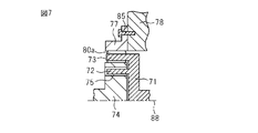
- FIG. 7 shows a second schematic cross-sectional view of the clutch in the present embodiment.
- FIG. 7 is a schematic cross-sectional view taken along line X in FIG.
- clutch 70 of the present embodiment includes an outer ring 77.
- the outer ring 77 is fixed to the housing 78 by screws 85.
- the outer ring 77 is fixed without moving during the period in which the clutch 70 is driven.
- the clutch 70 has an output shaft 74.
- the output shaft 74 rotates about the rotation center shaft 88 as a rotation center.
- a hole 75 is formed in the output shaft 74.
- a plurality of holes 75 are formed along the circumferential direction in which the output shaft 74 rotates.
- the output shaft 74 in the present embodiment has a polygonal cross section.
- the clutch 70 includes an input shaft 71.
- the input shaft 71 rotates about the rotation center shaft 88 as a rotation center.
- the input shaft 71 has an insertion part 72 and a holding part 73.
- the insertion part 72 and the holding part 73 rotate integrally.
- the plurality of insertion portions 72 are inserted into the hole portions 75 of the output shaft 74.
- the inner diameter of the hole portion 75 is formed to be larger than the outer diameter of the insertion portion 72.
- a gap is formed between the insertion portion 72 and the hole portion 75.
- the plurality of holding portions 73 are disposed between the outer ring 77 and the output shaft 74. The holding portion 73 faces the rollers 80a and 80b.
- Rollers 80a and 80b are disposed in the space between the output shaft 74 and the outer ring 77.
- the rollers 80a and 80b in the present embodiment are formed in a cylindrical shape.
- a spring 81 is disposed between the rollers 80a and 80b. The spring 81 urges the rollers 80a and 80b in a direction away from each other.
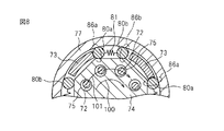
- the output shaft 74 and the outer ring 77 form locking portions 86a and 86b for locking the rollers 80a and 80b.
- the engaging portions 86a and 86b are portions where the distance between the outer surface of the output shaft 74 and the inner surface of the outer ring 77 is gradually reduced along the direction in which the rollers 80a and 80b are urged.
- the locking portions 86a and 86b are formed narrow so that the rollers 80a and 80b do not pass through.
- Clutch 70 in the present embodiment transmits this rotational force to output shaft 74 when the rotational force of motor 59 is input to input shaft 71.
- the clutch 70 is locked and interrupts the rotational force.
- the clutch 70 blocks the rotational force.
- the cylinder block 2 is urged away from the crankcase 1 by the lift spring 65.
- a force acts in a direction in which the cylinder block 2 approaches the crankcase 1 due to the influence of gravity or the negative pressure of the combustion chamber 5 in the intake stroke of the combustion cycle.
- the lift spring 65 by arranging the lift spring 65, the cylinder block 2 is always urged in the direction away from the crankcase 1, and the occurrence of vibration or the like in the cylinder block 2 can be suppressed.
- a force acts in a direction in which the cylinder block 2 is separated from the crankcase 1 due to the in-cylinder pressure.
- an arrow 100 is a direction corresponding to a direction in which the cylinder block 2 moves up with respect to the crankcase 1. That is, the rotation direction in which the combustion chamber 5 becomes large when the mechanical compression ratio becomes small and the piston 4 reaches top dead center is shown.
- a force is always applied to the cylinder block 2 in a direction away from the crankcase 1, and a force is applied to the output shaft 74 in the direction indicated by the arrow 100. That is, reverse input torque is acting in the direction indicated by arrow 100.
- the roller 80a is pressed by the spring 81 and is in contact with the locking portion 86a. For this reason, a wedge effect is generated in the roller 80a, the rotation of the output shaft 74 with respect to the outer ring 77 is prevented, and the output shaft 74 is locked. In this manner, the clutch 70 can block the rotational force from the output side corresponding to the direction in which the cylinder block 2 is separated from the crankcase 1. Similarly, when a rotational force in the direction opposite to the arrow 100 is applied to the output shaft 74, the roller 80b comes into contact with the locking portion 86b and the output shaft 74 is locked. In the clutch 70, when the motor 59 is not driven, the rollers 80 a and 80 b are locked to the locking portions 86 a and 86 b to lock the output shaft 74.
- FIG. 8 is a first schematic cross-sectional view of the clutch 70 for explaining the operation when the mechanical compression ratio is lowered.
- the cylinder block 2 is moved away from the crankcase 1.
- the insertion portion 72 of the input shaft 71 rotates in the direction indicated by the arrow 101.
- the holding part 73 contacts the roller 80a.
- FIG. 9 is a second schematic cross-sectional view of the clutch 70 for explaining the operation when the mechanical compression ratio is lowered.
- the holding portion 73 presses the roller 80a.
- the roller 80a is separated from the locking portion 86a.
- the output shaft 74 is unlocked, and can rotate in the direction indicated by the arrow 101 with respect to the outer ring 77.
- the insertion portion 72 of the input shaft 71 rotates in the direction indicated by the arrow 101
- the insertion portion 72 can press the hole 75 of the output shaft 74 and rotate the output shaft 74.
- the locked state by the roller 80b is also released.
- FIG. 10 is a schematic sectional view of the clutch 70 for explaining the operation when the mechanical compression ratio is increased.
- the cylinder block 2 is moved in a direction closer to the crankcase 1.
- the motor 59 By driving the motor 59, the insertion portion 72 and the holding portion 73 of the input shaft 71 are rotated in the direction indicated by the arrow 102.
- Rotating the insertion portion 72 and the holding portion 73 of the input shaft 71 in the direction indicated by the arrow 102 causes the holding portion 73 to press the roller 80b.
- the roller 80b is detached from the locking portion 86b, and the wedge effect of the roller 80b disappears.
- the rotational force of the input shaft 71 can be transmitted to the output shaft 74.
- the output shaft 74 rotates in the direction indicated by the arrow 102.
- the locked state by the roller 80a is also released.
- the rotational force of the input shaft 71 can be transmitted to the output shaft 74.
- the internal combustion engine of the present embodiment performs control for driving the variable compression ratio mechanism while the engine main body 90 is stopped.
- the stop of the engine main body 90 indicates not only that the combustion of fuel in the combustion chamber 5 is stopped, but also a state in which the torque output from the engine main body 90 is zero. That is, the engine speed is zero. Even in a state where the engine main body 90 is stopped, for example, the mechanical compression ratio may be changed in order to check whether there is an abnormality in the variable compression ratio mechanism.
- the force acting on cylinder block 2 is input to output shaft 74 of clutch 70 via camshafts 54 and 55, worm wheels 63 and 64, worms 61 and 62, and rotating shaft 60. .
- the direction of the reverse input torque input to the output shaft 74 at this time is a direction in which the cylinder block 2 is separated from the crankcase 1.
- the reverse input torque indicated by the arrow 100 is applied to the output shaft 74 in the clutch 70 even during the stop period of the engine main body 90.
- the roller 80a is in a state where it is locked to the locking portion 86a and the transmission of the reverse input torque to the input shaft 71 is blocked. That is, the clutch 70 is in a locked state.
- the locked state can be released by the same control as during the operation period of the engine body 90. Further, the locked state of the clutch 70 can be released with a relatively small input torque. That is, as shown in FIG. 10, by rotating the input shaft 71 in the direction shown by the arrow 102 by the motor 59, the locked state by the roller 80b can be released and the mechanical compression ratio can be increased. The output torque of the motor 59 at this time can be controlled to a predetermined set value.
- the inventors when releasing the lock state of the clutch 70, the inventors do not depend on the magnitude of the final input torque input to the input shaft 71, but whether the release is possible or not. It was found that the rate of increase of the input torque, that is, the torque gradient is related. Furthermore, the inventors have found that it is necessary to continue increasing the input torque at a predetermined time in order to release the locked state.
- the time during which the input torque of the clutch 70 continues to increase is referred to as the duration, and the time during which the input torque is applied to the clutch 70 is referred to as the application time.
- the grant time is longer than the duration.
- FIG. 11 is a graph for explaining the unlocking state with respect to the applied time and the input torque of the clutch 70 when the mechanical compression ratio is lowered.
- a constant reverse input torque is applied to the output shaft 74 of the clutch 70.
- An embodiment in which the clutch 70 is successfully released from the locked state is indicated by a solid line.
- release of a locked state is shown with the dashed-dotted line
- the comparative example 2 is shown with the dashed-two dotted line.
- the gradient of the input torque is large, and the locked state is released at the application time t id .
- the input torque T id is obtained.
- the gradient of the input torque T i is set small. In this case, although the input torque gradually increases, the locked state of the clutch 70 is maintained without being released.
- Comparative Example 2 is a state larger inclined in the input torque, short duration are continuing to increase in torque, increase in the input torque in the input torque T in is stopped. As a result, the locked state is maintained without being released.
- the inventors have found that in order to release the locked state of the clutch 70, the gradient of the input torque and the duration of continuing the increase of the input torque are important factors.
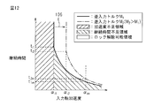
- FIG. 12 is a graph illustrating an area in which the clutch lock state can be released with respect to the acceleration and duration of the clutch input shaft.
- the horizontal axis is the acceleration of the input shaft 71 and corresponds to the gradient of the input torque.
- the vertical axis represents the duration for which the torque increase is continued.
- a solid line shows a graph in which the reverse input torque M 1 is applied to the output shaft 74.
- the duration time t i required for releasing the locked state becomes shorter as the acceleration ⁇ i of the input shaft increases.
- the input shaft acceleration ⁇ im is the maximum input shaft acceleration that the motor 59 can output.
- the duration t i1m or longer is the time required for unlocking.
- the motor of the present embodiment releases the locked state by continuing to increase the torque gradient for a predetermined time in a state that is greater than the input shaft acceleration ⁇ i1 and less than or equal to the input shaft acceleration ⁇ im .
- FIG. 12 shows a graph when the reverse input torque changes.
- the reverse input torque M 2 is larger than the reverse input torque M 1 .
- an area where the clutch 70 can be released is shifted as indicated by an arrow 105.
- an acceleration equal to or higher than the acceleration ⁇ i2 of the input shaft is required to release the clutch 70 from the locked state.
- a time longer than the duration t i2 is required.
- a time longer than the duration t i2m is necessary for releasing the locked state.
- the roller 80a bites into the engaging portion 86a composed of the output shaft 74 and the outer ring 77.
- the clutch torque is released by setting the gradient of the input torque of the clutch 70 and the duration for which the input torque continues to increase.
- a torque gradient and duration time corresponding to reverse input torque M can be selected to release clutch 70 from the locked state.
- the acceleration ⁇ i of the input shaft an arbitrary value capable of releasing the locked state can be selected. In the present embodiment, a region where the gradient of the input torque is large is selected. The maximum input shaft acceleration ⁇ im is selected from the region where the clutch 70 can be unlocked.
- FIG. 13 shows a flowchart of the first operation control for changing the mechanical compression ratio in the present embodiment.
- the operation control shown in FIG. 13 can be repeatedly performed by the electronic control unit 30 at predetermined time intervals, for example.
- step 120 it is determined whether or not the engine body 90 is stopped. For example, it is determined whether or not the engine speed is zero. In step 120, when the engine main body 90 is operating, this control is terminated. In step 120, when the engine main body 90 is in the stop period, the routine proceeds to step 121.
- step 121 it is determined whether or not a mechanical compression ratio change request has been detected. If the mechanical compression ratio change request is not detected, this control is terminated. If a request for changing the mechanical compression ratio is detected, the routine proceeds to step 122.
- step 122 it is determined whether or not the mechanical compression ratio is to be lowered. If it is determined in step 122 that the mechanical compression ratio is to be increased, the process proceeds to step 124. In step 124, the mechanical compression ratio is increased to the target mechanical compression ratio. In this case, the locked state can be released by supplying current to the motor 59 so as to have a predetermined torque gradient and duration. After releasing the locked state, the mechanical compression ratio can be increased to the target compression ratio. In step 122, when the mechanical compression ratio is decreased, the process proceeds to step 123.
- step 123 the eccentric shaft angle ⁇ in the current mechanical compression ratio state is calculated.
- the angle formed by the line connecting the center a of the circular cam 58 and the center b of the eccentric shaft 57 and the moving direction of the cylinder block 2 is the eccentric shaft angle.
- Called ⁇ Referring to FIG. 3, in the present embodiment, eccentric shaft angle ⁇ is 0 ° in the state where the mechanical compression ratio is the highest. As the mechanical compression ratio decreases, the eccentric shaft angle ⁇ increases. As shown in FIG. 5, when the mechanical compression ratio is at a minimum, the eccentric shaft angle ⁇ is approximately 180 °.
- the eccentric shaft angle ⁇ can be calculated based on the current mechanical compression ratio.
- the eccentric shaft angle ⁇ can be calculated based on the relative position detected by the relative position sensor 22 (see FIG. 1), for example.
- step 125 the reverse input torque applied to the output shaft 74 of the clutch 70 is calculated.
- a method of calculating the reverse input torque applied to the output shaft 74 of the clutch 70 during the stop period of the engine body 90 will be described.
- FIG. 14 is a graph of the load applied to the cylinder block 2 with respect to the eccentric shaft angle in the link mechanism of the variable compression ratio mechanism.
- the vertical axis represents the load applied to the cylinder block 2 by the lift spring 65 (see FIG. 1).
- the lift spring 65 As the mechanical compression ratio becomes lower, the cylinder block 2 moves away from the crankcase 1, so that the amount of contraction of the lift spring 65 decreases. For this reason, the load applied to the cylinder block 2 decreases as the eccentric shaft angle ⁇ increases. Even when the eccentric shaft angle becomes 180 °, the lift spring 65 is in a contracted state, and a minimum load is applied to the cylinder block 2.
- the load applied from the lift spring 65 to the cylinder block 2 is determined based on the eccentric shaft angle.
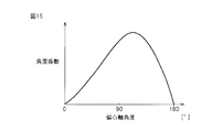
- FIG. 15 shows a graph of the angle coefficient with respect to the eccentric shaft angle.
- the angle coefficient of the vertical axis corresponds to the force transmission rate when the load applied to the cylinder block 2 by the link mechanism is transmitted to the worm wheels 63 and 64.
- the rotational force transmitted to the worm wheels 63 and 64 changes depending on the state of the link mechanism, that is, the eccentric shaft angle ⁇ . As the angle coefficient increases, the torque transmitted to the worm wheels 63 and 64 increases.
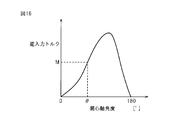
- FIG. 16 is a graph showing the reverse input torque with respect to the eccentric shaft angle.
- the torque applied to the worm wheels 63 and 64 can be calculated by multiplying the load applied to the cylinder block 2 shown in FIG. 14 by the angle coefficient shown in FIG. Then, the reverse input torque applied to the output shaft 74 of the clutch 70 can be calculated based on the gear ratio between the worm wheels 63 and 64 and the worms 61 and 62. It can be seen that the reverse input torque is a function of the eccentric shaft angle. Thus, the reverse input torque can be calculated based on the relative position of the cylinder block 2 with respect to the crankcase 1.
- a torque gradient input to the input shaft 71 of the clutch 70 is set.
- a duration for increasing the torque with the set torque gradient is set.
- set values using reverse input torque as a function are determined in advance. Referring to FIG. 12, for example, in the case of reverse input torque M 1 , a torque gradient corresponding to the acceleration ⁇ im of the input shaft is set, and an application time is selected by adding a margin to duration t i1m. ing.
- step 1208 the locked state is released.
- the control device supplies electric power to the motor 59 so as to achieve the set torque gradient and application time.
- FIG. 17 shows a graph for explaining the relationship between the current supplied to the motor and the input torque of the clutch.
- the input torque of the clutch 70 corresponds to the output torque of the motor 59.
- the motor 59 is controlled by duty ratio control. That is, the torque gradient of the output of the motor 59 can be adjusted by changing the ratio between the time during which the current is supplied to the motor 59 and the time during which the current supply is stopped.
- the graph with a duty ratio of 100% is indicated by a solid line, and the graph with a duty ratio of 50% is indicated by a one-dot chain line.
- the motor 59 is started at time t1.
- the input torque of the clutch 70 reaches a predetermined value and thereafter becomes constant.
- the increase rate of the output torque of the motor that is, the torque gradient applied to the input shaft 71 of the clutch 70 becomes larger than the control with the duty ratio of 50%.
- the torque gradient is changed by changing the duty ratio of the current supplied to the motor.
- step 1208 the locked state can be released.
- the control device supplies current to the motor 59 at the set application time and duty ratio.
- the locked state of the clutch 70 is released.
- step 129 the mechanical compression ratio is lowered to the target mechanical compression ratio.
- the mechanical compression ratio can be lowered even if the input torque of the clutch 70 is reduced.
- the control device can reduce the mechanical compression ratio to the target mechanical compression ratio at a predetermined low current value. This control is terminated when the mechanical compression ratio reaches the target mechanical compression ratio.
- the control device for an internal combustion engine in the present embodiment estimates the reverse input torque applied to the output shaft of the clutch. Based on the reverse input torque, a torque gradient output from the motor and a duration for continuing the torque increase are set. Set grant time based on duration. Then, the torque is increased based on the set torque gradient and the applied time, and the clutch is unlocked.
- the torque output from the motor and the electric power supplied to the motor can be optimized. For this reason, it can avoid that the capacity
- an electric motor is adopted as the rotating machine, and the control device controls the torque gradient by changing the supply pattern of electric power to the electric motor. Further, the duration is controlled by changing the time for supplying electric power to the electric motor. By performing this control, the torque gradient and duration applied to the input shaft of the clutch can be easily controlled.
- the rotating machine of the variable compression ratio mechanism is not limited to the electric motor, and any rotating machine capable of rotating the clutch input shaft can be employed.
- the rotating machine may be formed so as to rotate the input shaft of the clutch by a hydraulic actuator.
- the variable compression ratio mechanism in the present embodiment includes a lubricating oil supply device that supplies lubricating oil to the inside of the clutch 70.
- the state of the lubricating oil is taken into account when the mechanical compression ratio is lowered.
- the clutch 70 is disposed in an atmosphere of lubricating oil vapor.
- the engine body 90 is sealed with a boot seal so that the oil vapor stored in the oil pan does not leak to the outside.
- the clutch 70 is disposed inside the sealed space of the engine body 90.
- the oil pan and the sealing member function as a lubricating oil supply device.
- the lubricating oil supply device is not limited to this form, and may be formed so as to supply the lubricating oil directly into the clutch 70, for example.
- the friction coefficient at the sliding portion inside the clutch 70 is estimated, and the torque gradient and duration required for releasing the locked state of the clutch 70 are set based on the friction coefficient. To do. By reducing the friction coefficient, the torque gradient necessary for releasing the locked state can be reduced, and the duration time can also be shortened.
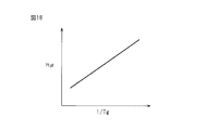
- FIG. 18 is a graph showing the relationship between the temperature of the lubricating oil and the friction coefficient.
- the friction coefficient ⁇ indicates a static friction coefficient on the contact surfaces of the rollers 80a and 80b.
- the rollers 80a and 80b and the outer ring 77 are in direct contact.
- An oil film is formed by a chemical reaction in the region between the rollers 80a and 80b and the outer ring 77.
- the friction coefficient ⁇ decreases as the temperature Tg of the lubricating oil increases. Based on the relationship shown in FIG. 18, the friction coefficient ⁇ can be calculated from the temperature Tg of the lubricating oil.
- the variable compression ratio mechanism of the present embodiment includes a temperature detector that detects the temperature of the lubricating oil.
- the temperature detector according to the present embodiment detects the temperature of the lubricating oil stored in the oil pan.
- the friction coefficient can be calculated based on the temperature of the lubricating oil.
- the torque gradient and the duration are controlled based on the temperature of the lubricating oil.
- a torque gradient can be set based on the coefficient of friction.
- the duration can be set based on the coefficient of friction. For example, a map in which reverse input torque and lubricating oil temperature are functions can be stored in advance in the control device. Alternatively, the set torque gradient and duration may be multiplied by a correction coefficient based on the friction coefficient.
- the torque gradient and duration required for releasing the locked state of the clutch 70 can be accurately set in order to consider the friction coefficient in the sliding portion inside the clutch 70. For this reason, it can be avoided that the capacity of the rotating machine becomes excessive. In addition, power consumption when releasing the locked state of the clutch 70 can be reduced.
- the third operation control of the present embodiment will be described.
- the state of the storage battery 92 when the clutch 70 is unlocked is detected. Then, based on the state of the storage battery 92, a supply pattern of power supplied to the motor 59 is set.
- FIG. 19 shows a schematic diagram of a power supply device that supplies power to the motor of the variable compression ratio mechanism.
- the internal combustion engine includes a storage battery 92 for supplying power to the motor 59, a power supply unit 94, and a voltage detector 93 that detects the output voltage of the storage battery 92.
- the output of the voltage detector 93 is input to the electronic control unit 30.
- the power supply unit 94 supplies power from the storage battery 92 to the motor 59 based on a command from the electronic control unit 30.
- the torque gradient and the duration are set so that the torque gradient of input shaft 71 of clutch 70 is increased.
- power consumption can be reduced, but the load on the storage battery 92 increases.
- the voltage drop of the storage battery 92 when the clutch 70 is unlocked becomes large. If the voltage drop of the storage battery 92 becomes large, there is a possibility that a malfunction may occur in the control of the mechanical compression ratio after the lock state is released. Alternatively, there is a possibility that a malfunction may occur in the control of other devices connected to the storage battery 92.
- the output voltage of the storage battery 92 is detected, and a voltage drop allowed when the mechanical compression ratio is reduced is calculated.
- the allowable voltage drop is equal to or greater than a predetermined determination value, the same control as the first operation control is performed.
- the torque gradient and the duration are set based on the allowable voltage drop.
- the torque gradient is set lower than the maximum torque gradient that the motor 59 can output.
- the duration is set longer than the minimum duration corresponding to the maximum torque gradient.
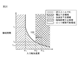
- FIG. 20 is a graph showing an area in which the clutch lock state can be released with respect to the input shaft acceleration and the duration time.
- FIG. 20 is a graph when the reverse input torque M 1 is used.
- the acceleration ⁇ i of the input shaft is set to the acceleration ⁇ im of the maximum input shaft of the motor 59, the voltage drop increases and the storage battery 92 becomes less than a predetermined voltage determination value.
- an allowable voltage drop is calculated based on the detected voltage of the storage battery 92.
- the acceleration ⁇ i3 of the input shaft is calculated based on the allowable voltage drop.
- the acceleration ⁇ i3 of the input shaft is set lower than the acceleration ⁇ im of the maximum input shaft.
- the duration t i3 is set based on the acceleration ⁇ i3 of the input shaft.
- the mechanical compression ratio is changed based on the set input shaft acceleration ⁇ i3 and duration t i3 .
- the output voltage of the storage battery becomes less than a predetermined voltage, and there is a problem in the control of the mechanical compression ratio after the locked state is released. It can be avoided. Moreover, it can suppress that a malfunction arises in control of another apparatus.
- FIG. 21 shows a flowchart of the third operation control in the present embodiment.
- This operation control can be repeatedly performed, for example, at predetermined time intervals.
- Steps 120 to 125 are the same as the first operation control shown in FIG.
- step 125 the reverse input torque is calculated based on the eccentric shaft angle.
- step 131 the voltage of the storage battery 92 is detected by the voltage detector 93. Then, based on the voltage of the storage battery 92, a voltage drop allowed by the control for reducing the mechanical compression ratio, that is, a voltage drop allowable value is set.
- step 132 it is determined whether or not the allowable voltage drop is greater than or equal to a predetermined determination value.
- a predetermined determination value for example, a voltage drop when the maximum torque gradient is selected can be set in advance. If the allowable voltage drop is equal to or greater than the determination value, it can be determined that the voltage output from the storage battery 92 is sufficiently high. In this case, the process proceeds to step 136.
- step 136 the maximum torque gradient that the motor 59 can output is set.
- step 137 a duration corresponding to the set torque gradient is set.
- step 138 the locked state is released based on the set torque gradient and duration.
- step 139 the mechanical compression ratio is lowered.
- step 132 if the voltage drop allowable value is less than the predetermined determination value, the process proceeds to step 133. In this case, if the mechanical compression ratio is reduced at the maximum torque gradient, it can be determined that the voltage of the storage battery 92 is insufficient.
- a torque gradient is set based on the allowable voltage drop.
- the value of the torque gradient having the voltage drop allowable value as a function can be determined in advance and stored in the electronic control unit 30.
- the torque gradient can be set based on the current output voltage of the storage battery 92.
- the duty ratio of the power supplied to the motor 59 can be set.
- step 134 the duration is set based on the set torque gradient.
- step 135 the locked state is released based on the set torque gradient and duration.
- step 139 the mechanical compression ratio is lowered.
- the third operation control it is possible to detect that the output voltage of the storage battery 92 has decreased and to control the output voltage of the storage battery 92 not to become too low after the mechanical compression ratio has decreased.
- the above-described operation control exemplifies control for changing the mechanical compression ratio during the stop period of the engine main body 90, but the operation control of the present invention can also be applied during the operation period of the engine main body 90.
- the fourth operation control for changing the mechanical compression ratio during the operation period of the engine body 90 will be described.
- FIG. 22 shows a graph for explaining the relationship between the crank angle and the in-cylinder pressure in the internal combustion engine of the present embodiment.
- the internal combustion engine in the present embodiment has a plurality of cylinders. In the present embodiment, four cylinders are formed. Each cylinder is supplied with a mixture of fuel and air, and when ignited, the fuel burns and the in-cylinder pressure rises.
- the in-cylinder pressure can be detected by an in-cylinder pressure sensor 23 (see FIG. 1).
- FIG. 22 shows the in-cylinder pressures of the first cylinder, the third cylinder, the fourth cylinder, and the second cylinder in the order of ignition.
- the crank angle on the horizontal axis corresponds to time.
- the in-cylinder pressure on the vertical axis corresponds to the force acting on the cylinder block 2 via the cylinder head 3.
- a maximum point 191 at which the maximum is reached by the combustion of fuel and a minimum point 192 at which the in-cylinder pressure is minimized are expressed.
- reverse input torque in the direction indicated by arrow 100 is applied to output shaft 74 by the in-cylinder pressure and the urging force of lift spring 65 during the operation period.
- the roller 80b can be easily detached from the locking portion 86b in order to press the roller 80b of the locking portion 86b on the side where the reverse input torque is not blocked. That is, the locked state can be easily released.
- the input shaft 71 rotates in the direction indicated by the arrow 101.
- the rotational direction of the input shaft 71 is the same as the rotational direction of the rotational force applied to the output shaft 74 indicated by the arrow 100.
- the reverse input torque applied to the output shaft 74 depends on the in-cylinder pressure. As the in-cylinder pressure increases, the reverse input torque applied to the output shaft 74 also increases. For this reason, the reverse input torque repeatedly increases and decreases.
- the period of vibration of the reverse input torque applied to the output shaft 74 is the same as the period of vibration of the in-cylinder pressure.
- the in-cylinder pressure increases from the crank angle CAa toward the crank angle CAb.
- the reverse input torque applied to the output shaft 74 also increases.
- the in-cylinder pressure increases, the amount that the roller 80a bites into the engaging portion 86a increases.
- a large force is required.
- the cylinder pressure decreases.
- the roller 80a can be unlocked with a small force by starting the pressing of the roller 80a.
- the operation of the motor 59 of the driving device is started at the maximum point 191 of the in-cylinder pressure.
- the control device of the present embodiment controls the motor 59 so that the roller 80a is separated from the locking portion 86a before the period S in which the in-cylinder pressure maximum point 191 shifts to the minimum point 192 ends.
- the locked state of the clutch 70 can be released with a small driving force.
- the locked state of the clutch 70 can be released without performing the above-described operation control for setting the torque gradient and the duration time.
- the fluctuation of the in-cylinder pressure is not sufficiently transmitted to the output shaft 74 of the clutch 70 due to the abnormality of the variable compression ratio mechanism or the aging of the parts constituting the eccentric shaft.
- the fluctuation of the rotational force due to the in-cylinder pressure may not be sufficiently transmitted to the output shaft 74 of the clutch 70 due to wear of the bearing of the eccentric shaft, reduction in power transmission efficiency of the worm gear due to the key, or the like.
- the variation in the in-cylinder pressure may not be sufficiently transmitted to the output shaft 74 due to deterioration of the lubricating oil that lubricates the eccentric shaft mechanism.
- the amplitude of the vibration of the reverse input torque applied to the output shaft 74 of the clutch 70 may be reduced.
- FIG. 23 is a graph showing the relationship between the crank angle and the reverse input torque applied to the output shaft of the clutch.
- FIG. 23 shows a graph at the start of use of the variable compression ratio mechanism and a graph at the time of deterioration over time.
- the start of use of the variable compression ratio mechanism for example, when it is new, there is no deterioration over time, so the amplitude of the reverse input torque increases.
- the amplitude of the reverse input torque decreases and becomes smaller when aging deteriorates or when the variable compression ratio mechanism is abnormal.
- the first operation control of the present embodiment when the amplitude of the vibration of the reverse input torque applied to the output shaft 74 becomes smaller than a predetermined determination value, the first operation control of the present embodiment is started.
- the same control as the third operation control is performed. That is, when lowering the mechanical compression ratio, the motor 59 is controlled by setting the torque gradient and duration.
- the first operation control is performed.
- FIG. 24 shows a flowchart of the fourth operation control in the present embodiment. This operation control can be repeatedly performed, for example, at predetermined time intervals.
- step 150 it is determined whether or not the engine body 90 is operating. For example, it is determined whether or not the engine speed is greater than zero. When the engine main body 90 is stopped, this control is terminated. When the engine body 90 is in the operation period, the routine proceeds to step 121.
- Step 121, step 122, and step 124 are the same as the first operation control (see FIG. 13).
- step 122 when the mechanical compression ratio is decreased, the process proceeds to step 151.
- step 151 the amplitude of the reverse input torque vibration is estimated.
- the internal combustion engine of the present embodiment includes a rotational force estimation device that estimates reverse input torque applied to the output shaft 74 of the clutch 70 during the operation period.
- the rotational force estimation device of the present embodiment includes a torque detector 89 that detects a reverse input torque of output shaft 74 of clutch 70.
- the torque detector 89 of the present embodiment is a strain gauge type.
- the torque detector 89 can detect the twist of the output shaft 74 and can detect the reverse input torque applied to the output shaft 74 based on the detected twist.
- the torque estimation device is not limited to this form, and any device that measures the reverse input torque applied to the output shaft 74 can be employed.
- a magnetostrictive torque sensor may be employed as the rotational force estimation device.
- the internal combustion engine of the present embodiment detects the amount of twist of output shaft 74 detected by the rotational force estimation device, and based on the detected amount of twist, the reverse input torque and minimum value of maximum point 193 are detected.
- the reverse input torque at point 194 is estimated.
- the amplitude ATrg of the vibration of the reverse input torque is calculated.
- one amplitude ATrg can be calculated based on one maximum point 193 and one minimum point 194.
- an average value of a plurality of amplitudes or the like may be employed.
- step 152 it is determined whether or not the amplitude ATrg of the vibration of the reverse input torque is equal to or larger than a predetermined amplitude determination value.
- a predetermined amplitude determination value it can be determined that the vibration amplitude of the reverse input torque for reducing the mechanical compression ratio is sufficiently large. In this case, the process proceeds to step 153.
- the lock state can be released by the lock release control during the normal operation described above.
- the locked state is released during period S.
- the mechanical compression ratio can be reduced to the target mechanical compression ratio.
- step 152 when the amplitude ATrg of the reverse input torque is less than a predetermined amplitude determination value, it is determined that the amplitude of the vibration of the reverse input torque is insufficient to reduce the mechanical compression ratio. it can. In this case, the process proceeds to step 125.
- Steps 125 to 128 are the same as the first operation control in the present embodiment. That is, the torque gradient and the duration for which the torque continues to be increased are calculated, and the clutch is unlocked based on the calculated torque gradient and the duration.
- the reverse input torque due to the in-cylinder pressure is taken into consideration.
- the twist amount of the output shaft 74 detected by the torque detector 89 is detected, and the reverse input torque at the maximum point 193 and the reverse input torque at the minimum point 194 are estimated based on the detected twist amount.
- the average value of the reverse input torque at the maximum point 193 and the reverse input torque at the minimum point 194 can be set as the reverse input torque applied to the output shaft.
- the reverse input torque may be estimated based on the output value of the in-cylinder pressure sensor and the eccentric shaft angle.
- step 129 the mechanical compression ratio can be lowered to the target mechanical compression ratio.
- the maximum value and the minimum value of the reverse input torque are estimated and the vibration amplitude of the reverse input torque is calculated.
- the present invention is not limited to this form, and the reverse input torque is calculated.
- Arbitrary control capable of determining whether or not the amplitude of vibration is less than the determination value can be performed. For example, when a maximum value (maximum value) of reverse input torque is detected in a predetermined internal combustion engine operating state, and the detected maximum value of reverse input torque is smaller than a predetermined maximum determination value, reverse input is performed. It can be determined that the amplitude of the vibration of the torque is less than a predetermined amplitude determination value.
- the third operation control can be incorporated in the fourth operation control. That is, when it is determined that the voltage of the storage battery is less than the allowable value when the locked state is released with the maximum torque gradient during the operation period, the power pattern supplied to the rotating machine based on the allowable voltage drop value of the storage battery Can be set.
- the clutch in the present embodiment transmits the rotational force from the input shaft in both the rotational direction in which the mechanical compression ratio increases and the rotational direction in which the mechanical compression ratio decreases to the output shaft, and the rotational force in both directions from the output shaft is transmitted. It is formed to block.
- the clutch is not limited to this configuration, and is configured to transmit the rotational force in both directions from the input shaft to the output side and to block the rotational force from the output shaft in the rotational direction in which the mechanical compression ratio decreases. I do not care.
- variable compression ratio mechanism of the present embodiment is interposed between the support structure and the cylinder block, includes a shaft including an eccentric shaft, and changes the relative position of the cylinder block with respect to the support structure.
- the present invention is not limited to this form, and the present invention is applied to a variable compression ratio mechanism including an eccentric shaft for changing the volume of the combustion chamber when the piston reaches top dead center and a drive device for rotating the eccentric shaft. can do.
- the internal combustion engine attached to the vehicle has been described as an example.
- the present invention is not limited to this embodiment, and the present invention is applied to an internal combustion engine disposed in an arbitrary device or facility. be able to.
Landscapes
- Engineering & Computer Science (AREA)
- General Engineering & Computer Science (AREA)
- Mechanical Engineering (AREA)
- Chemical & Material Sciences (AREA)
- Combustion & Propulsion (AREA)
- Physics & Mathematics (AREA)
- Fluid Mechanics (AREA)
- Output Control And Ontrol Of Special Type Engine (AREA)
- Braking Arrangements (AREA)
Abstract
内燃機関は、機械圧縮比を変更可能な可変圧縮比機構(A)を備え、可変圧縮比機構(A)は、ピストンが上死点に到達したときの燃焼室(5)の容積を変更するための駆動装置(59)を含む。駆動装置(59)は、回転機の回転力を伝達する駆動力伝達経路に配置されている逆入力遮断クラッチ(70)を含む。制御装置(30)は、逆入力遮断クラッチ(70)の出力軸に加わる逆入力トルクを推定し、逆入力トルクに基づいて、回転機が出力するトルク勾配およびトルクの増大を継続する継続時間を設定する。
Description
本発明は、内燃機関に関する。
内燃機関の燃焼室では、空気および燃料の混合気が圧縮された状態で点火される。混合気を圧縮するときの圧縮比は、内燃機関の出力および燃料消費量に影響を与えることが知られている。圧縮比を高くすることにより出力されるトルクを大きくすることができて、熱効率の向上を図ることができる。ところが、圧縮比を高くしすぎると、ノッキング等の異常燃焼が生じることが知られている。従来の技術においては、運転期間中に圧縮比を変更する可変圧縮比機構を備える内燃機関が知られている。
可変圧縮比機構は、ピストンが上死点に到達したときの燃焼室の容積を変更することにより圧縮比を変更することができる。燃焼室にて燃料が燃焼すると筒内圧が上昇する。そして、燃焼室を構成する部材に対して燃焼室の容積が大きくなる方向に力が作用し、この力は可変圧縮比機構にも作用する。特に、この力が燃焼室の容積を変更する機構を駆動するモータ等の回転機に伝達される虞がある。
このために、可変圧縮比機構には、筒内圧による回転力が回転機の出力軸に伝達されないように、筒内圧による回転力を遮断する逆入力遮断クラッチを配置することが知られている。逆入力遮断クラッチは、回転機の出力軸に加わる回転力を遮断するロック機能を有する。機械圧縮比を変更する場合には、逆入力遮断クラッチのロック状態を解除した上で燃焼室の容積を変更する。
特開2005-214088号公報には、往復操作子を進退動作させることによりピストンが上死点に到達したときの位置を変更することができる可変圧縮比エンジンが開示されている。この可変圧縮比エンジンは、アクチュエータ機構により圧縮比が変更される。アクチュエータ機構は、ボールねじと、モータの回転をボールねじのナットに伝達する回転伝達系と、回転伝達系に介在させたクラッチとを備える。この公報には、モータの駆動が入力される入力部材からナットへの回転を伝達するが、ナットから入力部材への回転の伝達を遮断する逆入力制限型のクラッチを採用することが開示されている。
特開2012-229764号公報においては、入力軸から出力軸へトルクが伝達されない時には出力軸の負荷トルクが入力軸へ伝達されるのを阻止するトルクダイオードを具え、トルクダイオードのロック状態を解除するロック解除装置が開示されている。このロック解除制御装置では、設定したロック解除トルクを所定時間加え続けてもロック状態が解除されない場合に、ロック解除トルクを徐々に増大させることが開示されている。
機械圧縮比を変更する場合には、逆入力遮断クラッチのロック状態を解除する必要がある。機関本体の運転中には、逆入力遮断クラッチの出力軸に筒内圧による回転力が加わる。筒内圧は時間とともに変化し、逆入力遮断クラッチのロック状態を解除するために必要なトルクは時間と共に変化する。
機械圧縮比の変更は、機関本体を駆動している期間中に限られず、機関本体を停止している期間中に実施する場合がある。たとえば、機関本体を始動する直前に、可変圧縮比機構の異常を検出するために機械圧縮比を変更する場合がある。または、内燃機関に加えて電動機を動力源とするハイブリッド駆動装置においては、機関本体を一時的に停止する期間がある。この期間中に偏心軸の表面等に油膜を形成して軸受の固着を回避するために、機械圧縮比を変更する場合がある。
このように、機関本体の運転中および停止期間中の両方の期間中に生じる全ての状態において、逆入力遮断クラッチのロック状態を解除するために、逆入力遮断クラッチの入力軸を駆動する回転機は出力トルクが大きな回転機を選定することが考えられる。ところが、回転機の容量を大きくすると、消費電力が大きくなったり、内燃機関の燃料の消費量が多くなったりするという問題がある。また、回転機が大型になり、回転機を配置する場所が制限されるという問題がある。
本発明は、逆入力遮断クラッチを含む可変圧縮比機構を備え、可変圧縮比機構を駆動する回転機を小型にできる内燃機関を提供することを目的とする。
本発明の内燃機関は、機械圧縮比を変更可能な可変圧縮比機構を備える。可変圧縮比機構は、ピストンが上死点に到達したときの燃焼室の容積を変更するための駆動装置と、駆動装置を制御する制御装置とを含む。駆動装置は、回転機と、回転機の回転力を伝達する駆動力伝達経路に配置されているクラッチとを含む。クラッチは、機械圧縮比を低下させる回転方向の出力軸に加わる逆入力トルクを遮断するように形成されている。制御装置は、クラッチの出力軸に加わる逆入力トルクを推定し、逆入力トルクに基づいて、回転機が出力するトルク勾配およびトルクの増大を継続する継続時間を設定し、トルク勾配および継続時間に基づいてクラッチのロック状態を解除する。
上記発明においては、クラッチは、回転機の回転力が入力される入力軸と、入力軸から回転力が伝達される出力軸と、クラッチの駆動中に移動しない外輪とを含み、ローラが出力軸と外輪との間に配置され、出力軸と外輪とはローラを係止させるための係止部を形成し、クラッチは、機械圧縮比を低下させる回転方向の逆入力トルクが出力軸に作用すると、ローラを係止部に係止させて出力軸を外輪に対してロックさせることで逆入力トルクを遮断するように形成されており、制御装置は、トルク勾配および継続時間に基づいて入力軸を回転させることにより、ローラを係止部から離して出力軸のロックを解除することができる。
上記発明においては、回転機は、電動機を含み、制御装置は、電動機に供給する電流のデューティ比を変更することによりトルク勾配を制御し、電動機に電力を供給する時間を変更することにより継続時間を制御することができる。
上記発明においては、可変圧縮比機構は、クラッチに潤滑油を供給する潤滑油供給装置と、潤滑油の温度を検出する温度検出器とを含み、制御装置は、潤滑油の温度を検出し、潤滑油の温度に基づいてトルク勾配および継続時間を制御することができる。
上記発明においては、電動機に電力を供給する蓄電池と、蓄電池の出力電圧を検出する電圧検出器とを備え、制御装置は、蓄電池の出力電圧を検出し、出力電圧が予め定められた電圧判定値よりも低い場合に、ロック状態を解除するために許容される電圧降下に基づいて、トルク勾配および継続時間を設定することができる。
上記発明においては、クランクケースを含む支持構造物と、支持構造物に支持されているシリンダブロックとを備え、可変圧縮比機構は、支持構造物とシリンダブロックとの間に介在し、偏心軸を含むシャフトを含み、駆動装置は、シャフトを回転させて支持構造物に対するシリンダブロックの相対位置を変更することにより燃焼室の大きさを変更することができる。
上記発明においては、支持構造物から離れる向きにシリンダブロックを付勢する付勢部材を備え、制御装置は、燃焼室における燃料の燃焼が停止している期間中に機械圧縮比を低下する場合に、付勢部材の付勢力に基づいてトルク勾配および継続時間を設定することができる。
上記発明においては、筒内圧を検出する筒内圧力検出器と、クラッチの出力軸に加わる逆入力トルクを推定する回転力推定装置とを備え、制御装置は、内燃機関の運転期間中に機械圧縮比を低下させる場合に、筒内圧を検出し、筒内圧が極大点から極小点まで移行する期間中に、クラッチの入力軸の駆動を開始するように回転機を制御し、クラッチの出力軸に加わる逆入力トルクの振動の振幅が予め定められた判定値未満の場合に、逆入力トルクを推定し、逆入力トルクに基づいてトルク勾配および継続時間を設定することができる。
本発明によれば、逆入力遮断クラッチを含む可変圧縮比機構を備え、可変圧縮比機構を駆動する回転機を小型にできる内燃機関を提供することができる。
図1から図24を参照して、実施の形態における内燃機関について説明する。本実施の形態においては、車両に取り付けられている火花点火式の内燃機関を例示して説明する。本実施の形態における内燃機関は、機械圧縮比を変更可能な可変圧縮比機構を備える。
図1は、実施の形態における内燃機関の概略図である。内燃機関は、機関本体90を備える。機関本体90は、機関本体90は、クランクケース1を含む支持構造物を備える。支持構造物は、クランクシャフトを支持するように形成されている。機関本体90は、シリンダブロック2、およびシリンダヘッド3を備える。シリンダブロック2の内部に形成された穴部には、ピストン4が配置されている。燃焼室5の頂面の中央部には、点火栓6が配置されている。本発明においては、任意のピストン4の位置において、ピストン4の冠面、シリンダブロック2の穴部、およびシリンダヘッド3に囲まれる空間を燃焼室と称する。また、燃焼室5の圧力、すなわち筒内圧を検出する筒内圧力検出器としての筒内圧センサ23が配置されている。
シリンダヘッド3には、吸気ポート8および排気ポート10が形成されている。吸気ポート8の端部には吸気弁7が配置されている。吸気弁7は、吸気カム49が回転することにより開閉する。排気ポート10の端部には、排気弁9が配置されている。吸気ポート8は、吸気枝管11を介してサージタンク12に連結されている。吸気枝管11には夫々対応する吸気ポート8内に向けて燃料を噴射するための燃料噴射弁13が配置されている。なお、燃料噴射弁13は吸気枝管11に取付ける代りに、各燃焼室5に直接的に燃料を噴射するように配置されていても構わない。
サージタンク12は、吸気ダクト14を介してエアクリーナ15に連結されている。吸気ダクト14の内部にはアクチュエータ16によって駆動されるスロットル弁17が配置されている。また、吸気ダクト14の内部には、例えば熱線を用いた吸入空気量検出器18が配置される。一方、排気ポート10は、排気マニホールド19を介して例えば三元触媒を内蔵した触媒装置20に連結されている。排気マニホールド19には空燃比センサ21が配置されている。
本実施の形態における内燃機関は、ピストン4が圧縮上死点に位置するときの燃焼室5の容積を変更可能な可変圧縮比機構Aを備える。可変圧縮比機構Aは、クランクケース1に対するシリンダブロック2のシリンダ軸線方向における相対位置を変化させるように形成されている。クランクケース1とシリンダブロック2との間には、付勢部材としてのリフトスプリング65が配置されている。リフトスプリング65は、クランクケース1から離れる向きにシリンダブロック2を付勢するように形成されている。なお、付勢部材としては、この形態に限られず、クランクケースから離れる向きにシリンダブロックを付勢する任意の部材を採用することができる。
クランクケース1およびシリンダブロック2には、クランクケース1に対するシリンダブロック2の相対位置を検出するための相対位置センサ22が取付けられている。相対位置センサ22からはクランクケース1とシリンダブロック2との間隔の変化を示す出力信号が出力される。スロットル弁駆動用のアクチュエータ16にはスロットル弁開度を示す出力信号を発生するスロットル開度センサ24が取付けられている。
本実施の形態における内燃機関の制御装置は、電子制御ユニット30を含む。本実施の形態における電子制御ユニット30は、デジタルコンピュータを含む。デジタルコンピュータは、双方向性バス31によって互いに接続されたROM(リードオンリメモリ)32、RAM(ランダムアクセスメモリ)33、CPU(マイクロプロセッサ)34、入力ポート35および出力ポート36を含む。
吸入空気量検出器18、空燃比センサ21、相対位置センサ22、筒内圧センサ23、およびスロットル開度センサ24の出力信号は夫々対応するAD変換器37を介して入力ポート35に入力される。また、アクセルペダル40にはアクセルペダル40の踏込み量に比例した出力電圧を発生する負荷センサ41が接続されている。負荷センサ41の出力電圧は対応するAD変換器37を介して入力ポート35に入力される。負荷センサ41の出力により要求負荷を検出することができる。更に、入力ポート35にはクランクシャフトが例えば30°回転する毎に出力パルスを発生するクランク角センサ42が接続されている。クランク角センサ42の出力により、クランク角度および機関回転数を検出することができる。
一方、出力ポート36は、対応する駆動回路38を介して点火栓6、燃料噴射弁13、スロットル弁駆動用のアクチュエータ16、および可変圧縮比機構Aに接続される。これらの装置は、電子制御ユニット30により制御されている。
図2に、本実施の形態における可変圧縮比機構の分解斜視図を示す。図3に本実施の形態における可変圧縮比機構の第1の概略断面図を示す。図2および図3を参照して、シリンダブロック2の両側壁の下方には互いに間隔を隔てた複数個の突出部50が形成されている。各突出部50には断面形状が円形のカム挿入孔51が形成されている。一方、クランクケース1の上壁には互いに間隔を隔てて、突出部50同士の間に嵌合される複数個の突出部52が形成されている。これらの突出部52にも断面形状が円形のカム挿入孔53が形成されている。
本実施の形態における可変圧縮比機構は、偏心軸を含むシャフトとしてのカムシャフト54,55を含む。カムシャフト54,55は、クランクケース1とシリンダブロック2との間に介在する。各カムシャフト54,55上には、一つおきに各カム挿入孔53内に回転可能に挿入される円形カム58が配置されている。これらの円形カム58は各カムシャフト54,55の回転軸線と共軸をなす。一方、各円形カム58の両側には、図3に示すように各カムシャフト54,55の回転軸線に対して偏心して配置された偏心軸57が延びている。この偏心軸57には、別の円形カム56が偏心して回転可能に取付けられている。図2に示されるように、円形カム56は、各円形カム58の両側に配置されている。これらの円形カム56は対応する各カム挿入孔51に回転可能に挿入されている。シリンダブロック2は、偏心軸57を含むカムシャフト54,55を介して、クランクケース1に支持されている。
図4に、本実施の形態における可変圧縮比機構の第2の概略断面図を示す。図5に、本実施の形態における可変圧縮比機構の第3の概略断面図を示す。図3から図5は、通常運転において機械圧縮比を変更するときの可変圧縮比機構の機能を説明する断面図である。図3に示す状態から各カムシャフト54,55上に配置された円形カム58を矢印68に示すように、互いに反対方向に回転させると偏心軸57が互いに近づく方向に移動する。偏心軸57は、それぞれのカムシャフト54,55の回転軸線の周りに回転する。シリンダブロック2は、矢印99に示すようにクランクケース1から離れる向きに移動する。このときに円形カム56は、カム挿入孔51内において回転し、図4に示されるように偏心軸57の位置が低い位置から中間高さ位置となる。次いで更に円形カム58を矢印68で示される方向に回転させると、シリンダブロック2は、矢印99に示すように更にクランクケース1から離れる向きに移動する。この結果、図5に示されるように偏心軸57は最も高い位置となる。
図3から図5には、それぞれの状態における円形カム58の中心aと偏心軸57の中心bと円形カム56の中心cとの位置関係が示されている。図3から図5を比較するとわかるように、クランクケース1とシリンダブロック2の相対位置は円形カム58の中心aと円形カム56の中心cとの距離によって定まる。円形カム58の中心aと円形カム56の中心cとの距離が大きくなるほど、シリンダブロック2はクランクケース1から離れる。即ち、可変圧縮比機構Aは回転するカムを用いたリンク機構によりクランクケース1とシリンダブロック2との間の相対位置が変化する。
シリンダブロック2がクランクケース1から離れると、ピストン4が圧縮上死点に位置するときの燃焼室5の容積は増大する。シリンダブロック2がクランクケース1に近づくと、ピストン4が圧縮上死点に位置するときの燃焼室5の容積は減少する。従って各カムシャフト54,55を回転させることによってピストン4が圧縮上死点に位置するときの燃焼室5の容積を変更することができる。
図2を参照して、本実施の形態の可変圧縮比機構は、燃焼室5の容積を変化させるためのカムシャフト54,55を回転させる駆動装置を含む。駆動装置は、回転機としてのモータ59を含む。更に、駆動装置は、クラッチ70、ウォーム61,62およびウォームホイール63,64等を含む。回転軸66は、モータ59の出力軸およびクラッチ70の入力軸に接続されている。回転軸60は、クラッチ70の出力軸に接続されている。回転軸60には、カムシャフト54,55を互いに反対方向に回転させるように、螺旋方向が逆向きの一対のウォーム61,62が取付けられている。ウォーム61,62と噛合するウォームホイール63,64がカムシャフト54,55の端部に固定されている。なお、駆動装置の回転機としては、モータ等の電動機に限られず、クラッチ70の入力軸を回転させることができる任意の装置を採用することができる。
この実施例では、モータ59を駆動することによってピストン4が圧縮上死点に位置するときの燃焼室5の容積を広い範囲に亘って変更することができる。可変圧縮比機構は、電子制御ユニット30に制御されており、カムシャフト54,55を回転させるモータ59は、対応する駆動回路38を介して出力ポート36に接続されている。
このように、本実施の形態における可変圧縮比機構は、クランクケース1に対してシリンダブロック2が相対的に移動することにより、ピストンが上死点に到達したときの燃焼室5の容積が可変に形成されている。本実施の形態においては、下死点から上死点までのピストンの行程容積とピストンが上死点に到達したときの燃焼室の容積のみから定まる圧縮比を機械圧縮比と称する。機械圧縮比は、吸気弁の閉弁時期等に依存せずに、(機械圧縮比)=(ピストンが上死点に到達したときの燃焼室の容積+ピストンの行程容積)/(ピストンが上死点に到達したときの燃焼室の容積)にて示すことができる。
図3に示す状態では、燃焼室5の容積が小さくなっており、機械圧縮比が高い状態である。吸入空気量が常時一定の場合には実際の圧縮比が高くなる。これに対して、図5に示す状態では、燃焼室5の容積が大きくなっており、機械圧縮比が低い状態である。吸入空気量が常時一定の場合には実際の圧縮比が低くなる。
本実施の形態における内燃機関は、運転期間中に機械圧縮比を変更することにより、実際の圧縮比を変更することができる。たとえば、内燃機関の運転状態に応じて、可変圧縮比機構により機械圧縮比を変更することができる。
図3から図5を参照して、偏心軸57は、カムシャフト54,55の回転軸、すなわち円形カム58の回転軸を中心に回転する。機械圧縮比を低下させる場合には、偏心軸57を矢印68に示す向きに回転させる。機械圧縮比を上昇させる場合には、偏心軸57を矢印69に示す向きに回転させる。
図2を参照して、本実施の形態における可変圧縮比機構は、モータ59が出力する回転力(出力トルク)をカムシャフト54,55に伝達する駆動力伝達経路に配置されているクラッチ70を含む。
本実施の形態におけるクラッチ70は、いわゆる逆入力遮断クラッチである。本実施の形態における逆入力遮断クラッチは、入力軸からの回転力を出力軸に伝達し、出力軸からの回転力を遮断するように形成されている。すなわち、クラッチ70は、モータ59から伝達される回転軸66の回転力はウォーム61,62に伝達し、ウォーム61,62から伝達される回転軸60の回転力は遮断して、モータ59に伝達しない構造を有する。本実施の形態においては、モータ59が出力するトルクによりクラッチ70の入力軸に加わるトルクをクラッチ70の入力トルクと称する。また、シリンダブロック2に作用する力により偏心軸57を介してクラッチ70の出力軸に加わるトルクをクラッチ70の逆入力トルクと称する。
本実施の形態のクラッチ70は、モータ59とウォーム62との間に配置されているが、この形態に限られず、モータ59の回転力をカムシャフト54,55に伝達する駆動力伝達経路の任意の位置に配置することができる。例えば、クラッチ70は、ウォームホイール63,64と、カムシャフト54,55との間に配置されていても構わない。この場合には、それぞれのカムシャフト54,55に対してクラッチを配置することができる。
図6に、本実施の形態におけるクラッチの第1の概略断面図を示す。図7に、本実施の形態におけるクラッチの第2の概略断面図を示す。図7は、図6におけるX線に沿って切断したときの概略断面図である。
図6および図7を参照して、本実施の形態のクラッチ70は、外輪77を含む。外輪77は、ねじ85によりハウジング78に固定されている。外輪77は、クラッチ70が駆動している期間中にも移動せずに固定されている。クラッチ70は、出力軸74を有する。出力軸74は、回転中心軸88を回転中心にして回転する。出力軸74には、穴部75が形成されている。穴部75は、出力軸74が回転する周方向に沿って複数個が形成されている。本実施の形態における出力軸74は、断面形状が多角形に形成されている。
クラッチ70は、入力軸71を含む。入力軸71は、回転中心軸88を回転中心にして回転する。入力軸71は、挿入部72と保持部73とを有する。挿入部72および保持部73は、一体的に回転する。
複数の挿入部72は、出力軸74の穴部75に挿入されている。穴部75の内径は挿入部72の外径よりも大きくなるように形成されている。挿入部72と穴部75との間には隙間が形成される。複数の保持部73は、外輪77と出力軸74との間に配置されている。また、保持部73はローラ80a,80bに対向している。
出力軸74と外輪77との間の空間には、ローラ80a,80bが配置されている。本実施の形態におけるローラ80a,80bは円柱状に形成されている。ローラ80aとローラ80bとの間には、スプリング81が配置されている。スプリング81は、ローラ80a,80bを互いに離す向きに付勢する。
出力軸74と外輪77とにより、ローラ80a,80bを係止させるための係止部86a,86bが形成される。係止部86a,86bは、ローラ80a,80bが付勢されている向きに沿って、出力軸74の外面と外輪77の内面との間隔が徐々に狭くなっている部分である。また、係止部86a,86bは、ローラ80a,80bが通過しないように狭く形成されている。
次に、本実施の形態おけるクラッチ70の動作について説明する。本実施の形態におけるクラッチ70は、モータ59の回転力が入力軸71に入力されると、この回転力を出力軸74に伝達する。一方で、クラッチ70は、カムシャフト54,55の側からの回転力が出力軸74に伝達されると、ロックされてこの回転力を遮断する。特に、クラッチ70は、機械圧縮比の低下する回転方向に回転する回転力がウォーム61,62から伝達されると、この回転力を遮断する。
図1を参照して、本実施の形態においては、リフトスプリング65によって、シリンダブロック2がクランクケース1から離れる向きに付勢されている。内燃機関の運転期間中には、重力の影響や燃焼サイクルの吸気行程において燃焼室5が負圧になる影響により、クランクケース1に対してシリンダブロック2が近づく向きに力が作用する。しかしながら、リフトスプリング65が配置されることにより、クランクケース1に対してシリンダブロック2が離れる向きに常に付勢され、シリンダブロック2に振動等が生じることを抑制できる。更に、燃焼室5において燃料の燃焼が行なわれごとに、筒内圧によりクランクケース1に対してシリンダブロック2が離れる方向に力が作用する。
シリンダブロック2がクランクケース1から離れる向きの付勢力はカムシャフト54,55に伝達されて回転力に変換される。カムシャフト54,55に生じる回転力は、ウォームホイール63,64およびウォーム61,62を介してクラッチ70の出力軸74に伝達される。図6を参照して、矢印100は、クランクケース1に対してシリンダブロック2が上昇する方向に対応する方向である。すなわち、機械圧縮比が小さくなり、ピストン4が上死点に到達したときの燃焼室5が大きくなる回転方向を示している。シリンダブロック2にはクランクケース1に対して離れる方向に常に力が加わり、出力軸74には矢印100に示す向きに力が加わっている。すなわち、矢印100に示す方向に逆入力トルクが作用している。
ローラ80aは、スプリング81に押圧されて係止部86aに接触している。このために、ローラ80aに楔の効果が生じて、外輪77に対する出力軸74の回転が阻止され、出力軸74がロックされる。このように、クラッチ70は、クランクケース1に対してシリンダブロック2が離れる方向に対応する出力側からの回転力を遮断することができる。また、同様に、矢印100と反対向きの回転力が出力軸74に加わった場合には、ローラ80bが係止部86bに接触して出力軸74がロックされる。クラッチ70は、モータ59を駆動しない場合に、ローラ80a,80bが係止部86a,86bに係止して出力軸74をロックする。
図8は、機械圧縮比を低下させるときの動作を説明するクラッチ70の第1の概略断面図である。機械圧縮比を低下させる場合には、クランクケース1に対してシリンダブロック2を離す向きに移動させる。モータ59を駆動することにより、入力軸71の挿入部72は、矢印101に示す向きに回転する。挿入部72が穴部75の内面に接触する前に、保持部73がローラ80aに接触する。
図9は、機械圧縮比を低下させるときの動作を説明するクラッチ70の第2の概略断面図である。入力軸71を更に回転させることにより、保持部73がローラ80aを押圧する。ローラ80aは、係止部86aから離れる。出力軸74は、ロック状態が解除され、外輪77に対して矢印101に示す方向に回転可能になる。入力軸71の挿入部72が、矢印101に示す向きに回転することにより、挿入部72が出力軸74の穴部75を押圧し、出力軸74を回転させることができる。このときに、出力軸74は、ローラ80bが係止部86bから離れる向きに回転するためにローラ80bによるロック状態も解除される。
図10は、機械圧縮比を上昇させるときの動作を説明するクラッチ70の概略断面図である。機械圧縮比を上昇させる場合には、クランクケース1に対してシリンダブロック2を近づける向きに移動させる。モータ59を駆動することにより、入力軸71の挿入部72および保持部73を、矢印102に示す向きに回転させる。
入力軸71の挿入部72および保持部73を矢印102に示す向きに回転させることにより、保持部73がローラ80bを押圧する。ローラ80bが係止部86bから脱離してローラ80bのくさび効果が消失する。次に、入力軸71の挿入部72が出力軸74の穴部75を押圧することにより、入力軸71の回転力を出力軸74に伝達することができる。出力軸74は、矢印102に示す向きに回転する。このときに、出力軸74は、ローラ80aが係止部86aから離脱する向きに回転するために、ローラ80aによるロック状態も解除される。このように、入力軸71の回転力を出力軸74に伝達することができる。
ところで、本実施の形態の内燃機関は、機関本体90を停止している期間中に可変圧縮比機構を駆動する制御を実施する。ここで、機関本体90の停止とは、燃焼室5における燃料の燃焼が停止しているのみではなく、機関本体90から出力されるトルクが零の状態を示す。すなわち、機関回転数が零である状態を示している。このような機関本体90が停止している状態においても、例えば、可変圧縮比機構の異常の有無を確認するために機械圧縮比を変更する場合がある。
図1を参照して、機関本体90を停止している期間中では、燃焼室5における燃料の燃焼が停止している。このため、筒内圧によりシリンダブロック2に加わる力は零である。ところが、クランクケース1とシリンダブロック2との間に配置されているリフトスプリング65により、シリンダブロック2はクランクケース1から離れる向きに付勢されている。
図2を参照して、シリンダブロック2に作用する力は、カムシャフト54,55、ウォームホイール63,64、ウォーム61,62および回転軸60を介して、クラッチ70の出力軸74に入力される。このときの出力軸74に入力される逆入力トルクの方向は、クランクケース1に対してシリンダブロック2が離れる方向である。
図6を参照して、機関本体90の停止期間中においても、クラッチ70には、出力軸74に対して矢印100に示す逆入力トルクが加えられている。ローラ80aは、係止部86aに係止して、入力軸71への逆入力トルクの伝達が遮断されている状態である。すなわち、クラッチ70は、ロック状態である。
機関本体90の停止期間中に、機械圧縮比を上昇させる場合には、機関本体90の運転期間中と同様の制御によりロック状態を解除することができる。また、比較的に小さな入力トルクにてクラッチ70のロック状態を解除することができる。すなわち、図10に示すように、モータ59により入力軸71を矢印102に示す向きに回転させることにより、ローラ80bによるロック状態を解除して、機械圧縮比を上昇させることができる。このときのモータ59の出力トルクは、予め定められた設定値に制御することができる。
一方で、機関本体90の停止期間中に機械圧縮比を低下させる場合には、図8および図9に示すように、モータ59により入力軸71を矢印101に示す向きに回転させることにより、ローラ80aを係止部86aから離脱させる。機関本体90の停止期間中には、出力軸74に加わる逆入力トルクは、ほぼ一定の状態になる。また、シリンダブロック2はクランクケース1から離れる向きに付勢されている。このために、機械圧縮比を低下させる場合にクラッチ70のロック状態を解除することができれば、小さなトルクにて容易に機械圧縮比を低下させることができる。
ここで、発明者らは、クラッチ70のロック状態を解除する場合に、解除の可否は入力軸71に入力される最終的な入力トルクの大きさのみに依存するのではなく、入力軸71の入力トルクの上昇速度、すなわちトルク勾配が関連することを見出した。更に、発明者らは、ロック状態を解除するためには、入力トルクの上昇を所定の時間にて継続する必要があることを見出した。本実施の形態では、クラッチ70の入力トルクの増大を継続している時間を継続時間と称し、クラッチ70に入力トルクを加えている時間を付与時間と称する。付与時間は、継続時間以上になる。
図11は、機械圧縮比を低下させる場合に、付与時間およびクラッチ70の入力トルクに対するロック解除の状態を説明するグラフである。クラッチ70の出力軸74には、一定の逆入力トルクが印加されている。クラッチ70のロック状態の解除に成功した実施例が実線にて示されている。また、ロック状態の解除に失敗した比較例1が一点鎖線にて、比較例2が二点鎖線にて示されている。
実施例の制御では、入力トルクの勾配が大きく、付与時間tidにてロック状態が解除されている。付与時間tidでは入力トルクTidになっている。これに対して、比較例1の制御では、入力トルクTiの勾配が小さく設定されている。この場合には、除々に入力トルクが増大するものの、クラッチ70のロック状態は解除されずに維持されている。また、比較例2では、入力トルクの勾配が大きい状態であるが、トルクの増大を継続している継続時間が短く、入力トルクTinで入力トルクの上昇が停止している。この結果、ロック状態は解除されずに維持されている。このように、発明者らは、クラッチ70のロック状態を解除するためには、入力トルクの勾配および入力トルクの上昇を継続する継続時間が重要な要因であることを見出した。
図12に、クラッチの入力軸の加速度および継続時間に対するクラッチのロック状態の解除が可能な領域を説明するグラフを示す。横軸は、入力軸71の加速度であり、入力トルクの勾配に相当する。縦軸は、トルク上昇を継続する継続時間である。
実線は、逆入力トルクM1を出力軸74に加えたグラフを示している。入力軸の加速度αi1未満の場合には、継続時間を長くしてもクラッチ70のロック状態を解除することができない。この領域は、トルク勾配が不足している領域である。そして、入力軸の加速度αi1以上であり、継続時間を長くするとロック状態を解除することができる。入力軸の加速度αi1にてロック状態を解除するためには、継続時間ti1以上の時間が必要になる。一方で、継続時間が所定の時間よりも短ければ、ロック状態を解除することができない。この領域は、継続時間が不足する領域になる。ロック状態を解除するために必要な継続時間tiは、入力軸の加速度αiが大きくなるほど短くなる。入力軸加速度αimは、モータ59が出力可能な最大の入力軸の加速度である。入力軸加速度αimでは、継続時間ti1m以上がロック解除に必要な時間である。このように、本実施の形態のモータは、入力軸の加速度αi1より大きく入力軸加速度αim以下の状態にて、所定の時間のトルク勾配の上昇を継続することによりロック状態を解除する。
図12には、逆入力トルクが変化した場合のグラフが示されている。逆入力トルクM2は、逆入力トルクM1よりも大きい。逆入力トルクM1から逆入力トルクM2に変化した場合には、矢印105に示すように、クラッチ70のロック状態を解除できる領域が移行する。逆入力トルクM2の場合には、クラッチ70のロック状態を解除するために入力軸の加速度αi2以上の加速度が必要である。入力軸の加速度αi2の時には継続時間ti2以上の時間が必要である。また、モータ59の最大の入力軸の加速度αimの場合には、継続時間ti2m以上の時間がロック状態の解除に必要になる。
図8に示すように、クラッチ70のロック状態を解除する前には、ローラ80aは、出力軸74および外輪77から構成される係止部86aに食い込んでいる。ローラ80aの係止部86aからの離脱を開始するためには、所定の大きさ以上のトルク勾配にて入力軸71を回転させる必要があると考えられる。また、ローラ80aの離脱が開始した後に、ローラ80aを係止部86aから離してロック状態を完全に解除するためには、ローラ80aの押圧を所定の継続時間の間、継続する必要があると考えられる。本実施の形態では、クラッチ70の入力トルクの勾配および入力トルクの増大を継続する継続時間を設定してクラッチのロック状態を解除する。
図12を参照して、クラッチ70の逆入力トルクMが定まれば、逆入力トルクMに応じたトルク勾配および継続時間を選定して、クラッチ70のロック状態を解除することができる。入力軸の加速度αiは、ロック状態の解除が可能な任意の値を選択することができる。本実施の形態では、入力トルクの勾配が大きくなる領域を選択している。クラッチ70のロック状態の解除が可能な領域のうち、最大の入力軸加速度αimを選択する。入力軸の加速度αiを大きくし、継続時間tiを短くすることにより、ロック状態を解除するために必要な電力量を小さくすることができる。すなわち、クラッチ70のロック状態を解除するための消費電力を抑制することができる。また、ロック状態の解除の応答性を向上させることができる。
図13に、本実施の形態における機械圧縮比を変更する第1の運転制御のフローチャートを示す。図13に示す運転制御は、電子制御ユニット30により、たとえば所定の時間間隔ごとに繰り返して行うことができる。
ステップ120においては、機関本体90が停止している状態か否かを判別する。例えば、機関回転数が零であるか否かを判別する。ステップ120において、機関本体90が運転期間中である場合には、この制御を終了する。ステップ120において、機関本体90が停止期間中である場合にはステップ121に移行する。
ステップ121においては、機械圧縮比の変更要求を検出したか否かを判別する。機械圧縮比の変更要求を検出していない場合には、この制御を終了する。機械圧縮比の変更要求を検出した場合には、ステップ122に移行する。
次に、ステップ122においては、機械圧縮比を低下させるか否かを判別する。ステップ122において、機械圧縮比を上昇させると判別した場合には、ステップ124に移行する。ステップ124においては、機械圧縮比を目標の機械圧縮比まで上昇する。この場合には、予め定められたトルク勾配および継続時間になるようにモータ59に電流を供給して、ロック状態を解除することができる。ロック状態を解除した後に機械圧縮比を目標圧縮比まで上昇させることができる。ステップ122において、機械圧縮比を低下させる場合には、ステップ123に移行する。
ステップ123においては、現在の機械圧縮比の状態における偏心軸角度θを算出する。図3から図5を参照して、本実施の形態においては、円形カム58の中心aと偏心軸57の中心bとを結ぶ線と、シリンダブロック2の移動方向とのなす角度を偏心軸角度θと称する。図3を参照して、本実施の形態では、機械圧縮比が最も高い状態では偏心軸角度θが0°である。機械圧縮比が低下するほど、偏心軸角度θが増大する。そして、図5に示すように、機械圧縮比が最小の状態では、偏心軸角度θがほぼ180°である。
偏心軸角度θは、現在の機械圧縮比に基づいて算出することができる。偏心軸角度θは、たとえば相対位置センサ22(図1参照)により検出される相対位置に基づいて算出することができる。
図13を参照して、ステップ125においては、クラッチ70の出力軸74に加わる逆入力トルクを算出する。ここで、機関本体90の停止期間中にクラッチ70の出力軸74に加わる逆入力トルクの算出方法について説明する。
図14は、可変圧縮比機構のリンク機構における偏心軸角度に対するシリンダブロック2に加わる荷重のグラフである。縦軸は、リフトスプリング65(図1参照)によりシリンダブロック2に印加される荷重を示している。機械圧縮比が低くなるほど、クランクケース1に対してシリンダブロック2が遠ざかるために、リフトスプリング65の縮み量は減少する。このために、偏心軸角度θが大きくなるほど、シリンダブロック2に加えられる荷重は小さくなる。偏心軸角度が180°になった場合においてもリフトスプリング65は縮んでいる状態であり、最小荷重がシリンダブロック2に加わっている。このように、偏心軸角度に基づいてリフトスプリング65からシリンダブロック2に印加される荷重が定まる。
図15に、偏心軸角度に対する角度係数のグラフを示す。縦軸の角度係数は、リンク機構によりシリンダブロック2に加わる荷重がウォームホイール63,64に伝達されるときの力の伝達率に対応する。リンク機構の状態、すなわち、偏心軸角度θに依存して、ウォームホイール63,64に伝達される回転力が変化する。角度係数が大きくなるほどウォームホイール63,64に伝達されるトルクは大きくなる。
図16は、偏心軸角度に対する逆入力トルクを示すグラフである。図14に示すシリンダブロック2に加わる荷重に対して図15に示す角度係数を乗じることにより、ウォームホイール63,64に加えられるトルクを算出することができる。そして、ウォームホイール63,64とウォーム61,62とのギヤ比に基づいて、クラッチ70の出力軸74に加わる逆入力トルクを算出することができる。逆入力トルクは、偏心軸角度の関数になっていることが分かる。このように、クランクケース1に対するシリンダブロック2の相対位置に基づいて、逆入力トルクを算出することができる。
図13を参照して、次に、出力軸74に加わる逆入力トルクに基づいて、クラッチ70のロック状態を解除するために必要なトルク勾配と入力トルクを増大する継続時間を設定する。
ステップ126においては、クラッチ70の入力軸71に入力されるトルク勾配を設定する。ステップ127においては、設定されたトルク勾配にてトルクを上昇させる継続時間を設定する。トルク勾配および継続時間は、例えば、逆入力トルクを関数にした設定値が予め定められている。図12を参照して、たとえば、逆入力トルクM1の場合には、入力軸の加速度αimに対応するトルク勾配に設定され、更に継続時間ti1mに余裕分を加算した付与時間が選定されている。
次に、ステップ128においてはロック状態を解除する。制御装置は、設定されたトルク勾配および付与時間になるように、モータ59に電力を供給する。
図17に、モータに供給する電流とクラッチの入力トルクとの関係を説明するグラフを示す。クラッチ70の入力トルクは、モータ59の出力トルクに対応する。本実施の形態では、デューティ比制御にてモータ59を制御している。すなわち、モータ59に、電流を供給している時間と電流の供給を停止する時間との比率を変更することにより、モータ59の出力のトルク勾配を調整することができる。
デューティ比が100%のグラフが実線で、デューティ比が50%のグラフが1点鎖線にて示されている。時刻t1においてモータ59を始動している。そして、時刻t2においてクラッチ70の入力トルクが所定の値まで到達して、その後に一定になっている。デューティ比が100%の制御では、デューティ比が50%の制御よりもモータの出力トルクの上昇速度、すなわちクラッチ70の入力軸71に加わるトルク勾配は大きくなる。デューティ比を増大することにより、入力軸71に入力するトルク勾配を増大することができる。本実施の形態においては、モータに供給する電流のデューティ比を変化させることにより、トルク勾配を変化させている。
図13を参照して、ステップ128において、ロック状態を解除することができる。制御装置は、設定された付与時間およびデューティ比にてモータ59に電流を供給する。クラッチ70のロック状態が解除される。
次に、ステップ129において、機械圧縮比を目標の機械圧縮比まで低下する。クラッチ70のロック状態を解除した後には、クラッチ70の入力トルクを小さくしても機械圧縮比を低下させることができる。制御装置は、予め定められた低い電流値にて機械圧縮比を目標機械圧縮比まで低下させることができる。機械圧縮比が目標機械圧縮比に到達した時に、この制御を終了する。
このように、本実施の形態における内燃機関の制御装置は、クラッチの出力軸に加わる逆入力トルクを推定する。逆入力トルクに基づいてモータが出力するトルク勾配およびトルクの増大を継続する継続時間を設定する。継続時間に基づいて付与時間を設定する。そして、設定されたトルク勾配と付与時間に基づいてトルクを増大して、クラッチのロック状態を解除する。この制御を採用することにより、モータが出力するトルクおよびモータ供給する電力を最適化することができる。このため、モータの容量が過大になることを回避することができて、モータの小型化を図ることができる。また、モータに供給する電力を低減することができる。
本実施の形態においては、回転機として電動機が採用され、制御装置は、電動機への電力の供給パターンを変更してトルク勾配を制御している。また、電動機に電力を供給する時間を変更して継続時間を制御している。この制御を実施することにより、クラッチの入力軸に加えるトルク勾配および継続時間を容易に制御することができる。
なお、可変圧縮比機構の回転機としては、電動機に限られず、クラッチの入力軸を回転可能な任意の回転機を採用することができる。たとえば、回転機は、油圧によるアクチュエータによりクラッチの入力軸を回転するように形成されていても構わない。
次に、本実施の形態の第2の運転制御について説明する。クラッチ70の内部では摺動する部分があるために、クラッチ70の内部には潤滑油が供給される。クラッチ70のロック状態を解除する場合には、ローラ80a,80bに対して、外輪77および出力軸74が摺動する。本実施の形態における可変圧縮比機構は、クラッチ70の内部に潤滑油を供給する潤滑油供給装置を備える。第2の運転制御では、機械圧縮比を低下させるときに潤滑油の状態を考慮する。
本実施の形態では、クラッチ70が潤滑油の蒸気の雰囲気中に配置されている。機関本体90は、オイルパンに貯留するオイルの蒸気が外部に漏れないようにブーツシールにより密閉されている。クラッチ70は、機関本体90の密閉空間の内部に配置されている。オイルパンおよび密閉部材が潤滑油供給装置として機能する。なお、潤滑油供給装置としては、この形態に限られず、たとえば、クラッチ70の内部に直接的に潤滑油を供給するように形成されていても構わない。
本実施の形態の第2の運転制御においては、クラッチ70の内部の摺動部分における摩擦係数を推定し、摩擦係数に基づいてクラッチ70のロック状態の解除に必要なトルク勾配および継続時間を設定する。摩擦係数が小さくなることにより、ロック状態を解除するために必要なトルク勾配を小さくすることができて、さらに、継続時間も短くすることができる。
図18は、潤滑油の温度と摩擦係数との関係を示すグラフである。クラッチ70のロック状態を解除する時には、動摩擦係数よりも静止摩擦係数が支配的になる。ここでの摩擦係数μは、ローラ80a,80bの接触面における静止摩擦係数を示している。たとえば、クラッチ70がロック状態であるときには、ローラ80a,80bと外輪77とが直接的に接触している。そして、ローラ80a,80bとの外輪77との間の領域における化学反応により油膜が形成される。潤滑油の温度Tgが高くなるほど摩擦係数μは低下する。図18に示す関係に基づいて、潤滑油の温度Tgにより摩擦係数μを算出することができる。
本実施の形態の可変圧縮比機構は、潤滑油の温度を検出する温度検出器を含む。本実施の形態の温度検出器は、オイルパンに貯留する潤滑油の温度を検出する。そして、潤滑油の温度に基づいて摩擦係数を算出することができる。
図13を参照して、第2の運転制御においては、潤滑油の温度に基づいてトルク勾配および継続時間を制御する。ステップ126において、摩擦係数に基づいてトルク勾配を設定することができる。ステップ127において、摩擦係数に基づいて継続時間を設定することができる。たとえば、逆入力トルクと潤滑油の温度とを関数にしたマップを予め制御装置に記憶させておくことができる。または、設定したトルク勾配および継続時間に対して摩擦係数に基づく補正係数を乗算しても構わない。
第2の運転制御においては、クラッチ70の内部の摺動部分における摩擦係数を考慮するために、クラッチ70のロック状態の解除に必要なトルク勾配および継続時間を正確に設定することができる。このために、回転機の容量が過大になることを回避することができる。また、クラッチ70のロック状態を解除するときの消費電力を低減することができる。
次に、本実施の形態の第3の運転制御について説明する。第3の運転制御においては、クラッチ70のロック状態を解除するときの蓄電池92の状態を検出する。そして、蓄電池92の状態に基づいて、モータ59に供給する電力の供給パターンを設定する。
図19に、可変圧縮比機構のモータに電力を供給する電力供給装置の概略図を示す。内燃機関は、モータ59に電力を供給するための蓄電池92と、電力供給ユニット94と、蓄電池92の出力電圧を検出する電圧検出器93とを備える。電圧検出器93の出力は、電子制御ユニット30に入力される。電力供給ユニット94は、電子制御ユニット30の指令に基づいて、蓄電池92からモータ59に電力を供給する。
図12を参照して、前述の運転制御ではクラッチ70の入力軸71のトルク勾配が大きくなるように、トルク勾配および継続時間を設定する。この制御では、消費電力を低減することができるが、蓄電池92の負荷が大きくなる。そして、クラッチ70のロック状態を解除したときの蓄電池92の電圧降下が大きくなる。蓄電池92の電圧降下が大きくなると、ロック状態を解除した後の機械圧縮比の制御に不具合が生じる虞がある。または、蓄電池92に接続されている他の装置の制御に不具合が生じる虞がある。
第3の運転制御では、クラッチ70のロック状態を解除する前に、蓄電池92の出力電圧を検出し、機械圧縮比の低下の際に許容される電圧降下を算出する。許容される電圧降下が予め定められた判定値以上の場合には、第1の運転制御と同様の制御を実施する。一方で、許容される電圧降下が予め定められた判定値未満の場合には、許容される電圧降下に基づいてトルク勾配および継続時間を設定する。トルク勾配は、モータ59が出力可能な最大のトルク勾配よりも低く設定される。また、継続時間は最大のトルク勾配に対応する最小の継続時間よりも長く設定される。
図20は、入力軸加速度および継続時間に対してクラッチのロック状態の解除が可能な領域を示すグラフである。図20は、逆入力トルクM1のときのグラフである。この実施例では、入力軸の加速度αiをモータ59の最大の入力軸の加速度αimに設定すると、電圧降下が大きくなり、蓄電池92は所定の電圧判定値未満になってしまう。このために、検出した蓄電池92の電圧に基づいて、許容される電圧降下を算出する。そして、許容される電圧降下に基づいて入力軸の加速度αi3を算出する。矢印103に示す様に、入力軸の加速度αi3は、最大の入力軸の加速度αimよりも低く設定される。そして、入力軸の加速度αi3に基づいて継続時間ti3が設定される。設定された入力軸の加速度αi3および継続時間ti3に基づいて、機械圧縮比が変更される。
第3の運転制御を実施することにより、クラッチ70のロック状態を解除した場合に、蓄電池の出力電圧が所定の電圧未満になって、ロック状態を解除した後の機械圧縮比の制御に不具合が生じることを回避できる。また、他の装置の制御に不具合が生じることを抑制することができる。
図21に、本実施の形態における第3の運転制御のフローチャートを示す。この運転制御は、たとえば、予め定められた時間間隔ごとに繰り返して実施することができる。ステップ120からステップ125までは、図13に示す第1の運転制御と同様である。ステップ125においては、偏心軸角度に基づいて逆入力トルクを算出する。
次に、ステップ131において、電圧検出器93により蓄電池92の電圧を検出する。そして、蓄電池92の電圧に基づいて機械圧縮比を低下させる制御で許容される電圧降下、すなわち電圧降下許容値を設定する。
次に、ステップ132においては、電圧降下許容値が予め定められた判定値以上か否かが判別される。ここでの判定値は、たとえば、最大のトルク勾配を選択した場合の電圧降下を予め設定することができる。電圧降下許容値が判定値以上であれば、蓄電池92が出力する電圧は十分に高いと判別することができる。この場合には、ステップ136に移行する。
ステップ136においては、モータ59が出力可能な最大のトルク勾配を設定する。ステップ137においては、設定されたトルク勾配に対応する継続時間を設定する。ステップ138においては、設定されたトルク勾配と継続時間に基づいてロック状態を解除する。次に、ステップ139において機械圧縮比を低下させる。
ステップ132において、電圧降下許容値が予め定められた判定値未満である場合には、ステップ133に移行する。この場合には、最大のトルク勾配にて機械圧縮比を低下すると蓄電池92の電圧が不足すると判別することができる。
ステップ133においては、電圧降下許容値に基づいてトルク勾配を設定する。電圧降下許容値を関数にするトルク勾配の値は、予め定めておいて電子制御ユニット30に記憶させておくことができる。このように、現在の蓄電池92の出力電圧に基づいて、トルク勾配を設定することができる。本実施の形態では、モータ59に供給する電力のデューテイ比を設定することができる。
次に、ステップ134においては、設定されたトルク勾配に基づいて継続時間を設定する。ステップ135においては、設定されたトルク勾配および継続時間によりロック状態を解除する。次に、ステップ139において機械圧縮比を低下させる。
このように、第3の運転制御においては、蓄電池92の出力電圧が低下したことを検出し、機械圧縮比が低下した後に蓄電池92の出力電圧が低くなりすぎないように制御することができる。
前述の運転制御では機関本体90の停止期間中に機械圧縮比を変更する制御を例示しているが、本発明の運転制御は、機関本体90の運転期間中にも適用することができる。次に、機関本体90の運転期間中に機械圧縮比を変更する第4の運転制御について説明する。
図22に、本実施の形態の内燃機関におけるクランク角度と、筒内圧との関係を説明するグラフを示す。本実施の形態における内燃機関は、複数の気筒を有する。本実施の形態においては、4個の気筒が形成されている。それぞれの気筒には燃料と空気の混合気が供給されて、点火することにより燃料が燃焼し、筒内圧が上昇する。筒内圧は、筒内圧センサ23(図1参照)により検出することができる。図22には、点火の順序に従って、第1気筒、第3気筒、第4気筒および第2気筒の筒内圧が記載されている。横軸のクランク角度は、時間に対応する。縦軸の筒内圧は、シリンダヘッド3を介してシリンダブロック2に作用する力に対応する。筒内圧には、燃料が燃焼することにより極大になる極大点191と、筒内圧が極小になる極小点192とが発現している。
図10を参照して、運転期間中には筒内圧およびリフトスプリング65の付勢力により、出力軸74には、矢印100に示す向きの逆入力トルクが加わっている。機械圧縮比を上昇させる場合には、逆入力トルクを遮断していない側の係止部86bのローラ80bを押圧するために、容易にローラ80bを係止部86bから離脱させることができる。すなわち、容易にロック状態を解除することができる。
図8および図9を参照して、機械圧縮比を低下させる場合には、入力軸71が矢印101に示す向きに回転する。入力軸71の回転方向は、矢印100に示す出力軸74に加わる回転力の回転方向と同じになる。出力軸74に加わる逆入力トルクは筒内圧に依存する。筒内圧が大きくなると、出力軸74に加わる逆入力トルクも大きくなる。このために、逆入力トルクも増大と減少とを繰り返す。出力軸74に加わる逆入力トルクの振動の周期は、筒内圧の振動の周期と同様になる。
図22を参照して、例えば、クランク角度CAaからクランク角度CAbに向かうにつれて、筒内圧が上昇する。出力軸74に加わる逆入力トルクも増大する。筒内圧が上昇するときには、ローラ80aが係止部86aに食い込む量が増大する。この時に、機械圧縮比を低下させるために、保持部73にてローラ80aを押圧してローラ80aのロック状態を解除しようとしても、大きな力が必要になる。
一方で、筒内圧が低下している場合には、出力軸74に加わる逆入力トルクが減少する。ローラ80aが係止部86aに食い込む量が小さくなる。ローラ80aは、係止部86aから離脱する向きに相対移動している。この時に、保持部73によりローラ80aを押圧すると、係止部86aからのローラ80aの離脱を促進し、小さな力にてローラ80aの係止を解除することができる。
例えばクランク角度CA1(筒内圧の極大点191)からクランク角度CA2(筒内圧の極小点192)までの期間Sにおいては、筒内圧が減少している。期間Sにおいて、機械圧縮比を低下させるために、ローラ80aの押圧を開始することにより、小さな力にてローラ80aの係止を解除することができる。本実施の形態においては、筒内圧の極大点191において、駆動装置のモータ59の作動を開始している。
ここで、期間Sを経過すると筒内圧が再び上昇する。このために、ローラ80aの係止部86aからの離脱は、期間S内に終了することが好ましい。すなわち、期間Sの期間内に係止部86aからローラ80aが離れることが好ましい。本実施の形態の制御装置は、筒内圧の極大点191から極小点192に移行する期間Sが終了するまでに、係止部86aからローラ80aが離れるようにモータ59を制御している。
このように、筒内圧の極大点191から極小点192に移行する期間中にクラッチ70のロック状態を解除することにより、小さな駆動力にてクラッチ70のロック状態を解除することができる。機械圧縮比を低下する場合に、トルク勾配と継続時間を設定する前述の運転制御を実施しなくてもクラッチ70のロック状態を解除することができる。
ところが、内燃機関の使用を継続すると、可変圧縮比機構の異常や偏心軸を構成する部品の経年劣化等により、筒内圧の変動が十分にクラッチ70の出力軸74に伝達されない場合が生じ得る。たとえば、偏心軸の軸受けの摩耗や、かたぎによるウォームギヤの動力伝達効率の低下等により、筒内圧による回転力の変動がクラッチ70の出力軸74に十分に伝達されない場合がある。または、偏心軸の機構を潤滑する潤滑油の劣化により筒内圧の変動が出力軸74に十分に伝達されない場合がある。この結果、クラッチ70の出力軸74に加わる逆入力トルクの振動の振幅が小さくなる場合がある。
図23は、クランク角度とクラッチの出力軸に加わる逆入力トルクとの関係を示すグラフである。図23には、可変圧縮比機構の使用開始時のグラフと経年劣化時のグラフとが示されている。可変圧縮比機構の使用開始時、たとえば新品の時には経年劣化がないために、逆入力トルクの振幅が大きくなる。これに対して、経年劣化時や可変圧縮比機構の異常時には、逆入力トルクの振幅が減少して小さくなる。
筒内圧の極大点193から極小点194に移行する期間中にクラッチ70のロック状態を解除する制御を実施している場合に、逆入力トルクの振動の振幅が小さくなると、クラッチ70のロック状態を解除することが困難になる場合がある。特に、機械圧縮比を低下する場合に、クラッチ70のロック状態を解除することが困難になる場合がある。
そこで、本実施の形態の内燃機関は、出力軸74に加わる逆入力トルクの振動の振幅が予め定められた判定値よりも小さくなった場合には、本実施の形態の第1の運転制御から第3の運転制御と同様の制御を実施する。すなわち、機械圧縮比を低下させる場合に、トルク勾配と継続時間を設定してモータ59を制御する。ここでは、第1の運転制御を実施する例を取り上げて説明する。
図24に、本実施の形態における第4の運転制御のフローチャートを示す。この運転制御は、たとえば、予め定められた時間間隔ごとに繰り返して実施することができる。
ステップ150においては、機関本体90が運転期間中であるか否かを判別する。たとえば、機関回転数が零よりも大きいか否かを判別する。機関本体90が停止している場合には、この制御を終了する。機関本体90が運転期間中の場合には、ステップ121に移行する。
ステップ121、ステップ122およびステップ124は、第1の運転制御と同様である(図13参照)。ステップ122において、機械圧縮比を低下させる場合には、ステップ151に移行する。
ステップ151においては、逆入力トルクの振動の振幅を推定する。ここで、逆入力トルクの振動の振幅の推定制御について説明する。本実施の形態の内燃機関は、運転期間中にクラッチ70の出力軸74に加わる逆入力トルクを推定する回転力推定装置を含む。図2を参照して、本実施の形態の回転力推定装置は、クラッチ70の出力軸74の逆入力トルクを検出するトルク検出器89を含む。
本実施の形態のトルク検出器89は、歪みゲージ式である。トルク検出器89は、出力軸74のねじれを検出し、検出したねじれに基づいて出力軸74に加わる逆入力トルクを検出することができる。回転力推定装置としては、この形態に限られず、出力軸74に加わる逆入力トルクを測定する任意の装置を採用することができる。たとえば、回転力推定装置としては、磁歪式のトルクセンサを採用しても構わない。
図23を参照して、本実施の形態の内燃機関は、回転力推定装置にて検出した出力軸74のねじれ量を検出し、検出したねじれ量に基づいて極大点193の逆入力トルクおよび極小点194の逆入力トルクを推定する。そして、逆入力トルクの極大値および極小値に基づいて、逆入力トルクの振動の振幅ATrgを算出する。振幅ATrgの算出においては、1つの極大点193と1つの極小点194とに基づいて1つの振幅ATrgを算出することができる。または、複数個の極大点193および複数の極小点194に基づいて、複数の振幅の平均値等を採用しても構わない。
図24を参照して、次に、ステップ152においては、逆入力トルクの振動の振幅ATrgが予め定められた振幅の判定値以上か否かを判別する。逆入力トルクの振幅ATrgが予め定められた振幅の判定値以上の場合には、機械圧縮比を低下させるための逆入力トルクの振動の振幅が十分に大きいと判別することができる。この場合には、ステップ153に移行する。
ステップ153においては、前述の通常運転の期間中のロック解除制御によりロック状態を解除することができる。たとえば、図22を参照して、期間Sの期間中にロック状態を解除する。そして、ステップ129において、目標機械圧縮比まで機械圧縮比を低下させることができる。
ステップ152において、逆入力トルクの振幅ATrgが予め定められた振幅の判定値未満の場合には、機械圧縮比を低下させるために逆入力トルクの振動の振幅が不十分であると判別することができる。この場合には、ステップ125に移行する。
ステップ125からステップ128は、本実施の形態における第1の運転制御と同様である。すなわち、トルク勾配とトルクの増大を継続する継続時間とを算出して、算出したトルク勾配および継続時間に基づいてクラッチのロック状態を解除する。
ここで、ステップ125の逆入力トルクの算出においては、筒内圧による逆入力トルクを考慮する。たとえば、トルク検出器89にて検出した出力軸74のねじれ量を検出し、検出したねじれ量に基づいて極大点193の逆入力トルクおよび極小点194の逆入力トルクを推定する。そして、極大点193の逆入力トルクおよび極小点194の逆入力トルクの平均値を、出力軸に加わる逆入力トルクとすることができる。または、筒内圧センサの出力値と偏心軸角度とに基づいて逆入力トルクを推定しても構わない。
そして、ステップ128においてロック状態を解除した後に、ステップ129において、目標機械圧縮比まで機械圧縮比を低下させることができる。
本実施の形態の第4の運転制御においては、逆入力トルクの極大値と極小値とを推定して逆入力トルクの振動の振幅を算出しているが、この形態に限られず、逆入力トルクの振動の振幅が判定値未満であるか否かを判別可能な任意の制御を実施することができる。たとえば、所定の内燃機関の運転状態において逆入力トルクの最大値(極大値)を検出し、検出した逆入力トルクの最大値が予め定められた最大値の判定値よりも小さい場合に、逆入力トルクの振動の振幅が予め定められた振幅の判定値未満であると判別することができる。
第4の運転制御についても第3の運転制御を組み込むことができる。すなわち、運転期間中に最大のトルク勾配にてロック状態を解除すると、蓄電池の電圧が許容値未満になると判別される場合には、蓄電池の電圧降下許容値に基づいて回転機に供給する電力パターンを設定することができる。
本実施の形態におけるクラッチは、機械圧縮比が上昇する回転方向および機械圧縮比が低下する回転方向の両方向の入力軸からの回転力を出力軸に伝達し、出力軸からの両方向の回転力を遮断するように形成されている。クラッチとしては、この形態に限られず、入力軸からの両方向の回転力を出力側に伝達し、機械圧縮比が低下する回転方向の出力軸からの回転力を遮断するように形成されていれば構わない。
更に、本実施の形態の可変圧縮比機構は、支持構造物とシリンダブロックとの間に介在し、偏心軸を含むシャフトを含み、支持構造物に対するシリンダブロックの相対位置を変更しているが、この形態に限られず、ピストンが上死点に到達したときの燃焼室の容積を変更するための偏心軸と、偏心軸を回転させるための駆動装置とを含む可変圧縮比機構に本発明を適用することができる。
本実施の形態においては、車両に取り付けられている内燃機関を例示して説明を行なったが、この形態に限られず、任意の装置や設備等に配置されている内燃機関に本発明を適用することができる。
上記の実施の形態は、組み合わせることができる。上述のそれぞれの図において、同一または相等する部分には同一の符号を付している。また、上述のそれぞれの制御においては、機能および作用が変更されない範囲において適宜ステップの順序を変更することができる。なお、上記の実施の形態は例示であり発明を限定するものではない。また、実施の形態においては、特許請求の範囲に示される形態の変更が含まれている。
1 クランクケース
2 シリンダブロック
5 燃焼室
22 相対位置センサ
23 筒内圧センサ
30 電子制御ユニット
54,55 カムシャフト
56,58 円形カム
57 偏心軸
59 モータ
65 リフトスプリング
70 クラッチ
71 入力軸
74 出力軸
77 外輪
80a,80b ローラ
89 トルク検出器
90 機関本体
92 蓄電池
93 電圧検出器
A 可変圧縮比機構
2 シリンダブロック
5 燃焼室
22 相対位置センサ
23 筒内圧センサ
30 電子制御ユニット
54,55 カムシャフト
56,58 円形カム
57 偏心軸
59 モータ
65 リフトスプリング
70 クラッチ
71 入力軸
74 出力軸
77 外輪
80a,80b ローラ
89 トルク検出器
90 機関本体
92 蓄電池
93 電圧検出器
A 可変圧縮比機構
Claims (8)
- 機械圧縮比を変更可能な可変圧縮比機構を備え、
可変圧縮比機構は、ピストンが上死点に到達したときの燃焼室の容積を変更するための駆動装置と、駆動装置を制御する制御装置とを含み、
駆動装置は、回転機と、回転機の回転力を伝達する駆動力伝達経路に配置されているクラッチとを含み、
クラッチは、機械圧縮比を低下させる回転方向の出力軸に加わる逆入力トルクを遮断するように形成されており、
制御装置は、クラッチの出力軸に加わる逆入力トルクを推定し、逆入力トルクに基づいて、回転機が出力するトルク勾配およびトルクの増大を継続する継続時間を設定し、前記トルク勾配および前記継続時間に基づいてクラッチのロック状態を解除することを特徴とする、内燃機関。 - クラッチは、回転機の回転力が入力される入力軸と、入力軸から回転力が伝達される出力軸と、クラッチの駆動中に移動しない外輪とを含み、ローラが出力軸と外輪との間に配置され、出力軸と外輪とはローラを係止させるための係止部を形成し、クラッチは、機械圧縮比を低下させる回転方向の逆入力トルクが出力軸に作用すると、ローラを係止部に係止させて出力軸を外輪に対してロックさせることで前記逆入力トルクを遮断するように形成されており、
制御装置は、前記トルク勾配および前記継続時間に基づいて入力軸を回転させることにより、ローラを係止部から離して出力軸のロックを解除する、請求項1に記載の内燃機関。 - 回転機は、電動機を含み、
制御装置は、電動機に供給する電流のデューティ比を変更することによりトルク勾配を制御し、電動機に電力を供給する時間を変更することにより継続時間を制御する、請求項1に記載の内燃機関。 - 可変圧縮比機構は、クラッチに潤滑油を供給する潤滑油供給装置と、潤滑油の温度を検出する温度検出器とを含み、
制御装置は、潤滑油の温度を検出し、潤滑油の温度に基づいて前記トルク勾配および前記継続時間を制御する、請求項1に記載の内燃機関。 - 電動機に電力を供給する蓄電池と、
蓄電池の出力電圧を検出する電圧検出器とを備え、
制御装置は、蓄電池の出力電圧を検出し、出力電圧が予め定められた電圧判定値よりも低い場合に、ロック状態を解除するために許容される電圧降下に基づいて、前記トルク勾配および前記継続時間を設定する、請求項3に記載の内燃機関。 - クランクケースを含む支持構造物と、
支持構造物に支持されているシリンダブロックとを備え、
可変圧縮比機構は、支持構造物とシリンダブロックとの間に介在し、偏心軸を含むシャフトを含み、
駆動装置は、シャフトを回転させて支持構造物に対するシリンダブロックの相対位置を変更することにより燃焼室の大きさを変更する、請求項1に記載の内燃機関。 - 支持構造物から離れる向きにシリンダブロックを付勢する付勢部材を備え、
制御装置は、燃焼室における燃料の燃焼が停止している期間中に機械圧縮比を低下する場合に、付勢部材の付勢力に基づいて前記トルク勾配および前記継続時間を設定する、請求項6に記載の内燃機関。 - 筒内圧を検出する筒内圧力検出器と、
クラッチの出力軸に加わる逆入力トルクを推定する回転力推定装置とを備え、
制御装置は、内燃機関の運転期間中に機械圧縮比を低下させる場合に、筒内圧を検出し、筒内圧が極大点から極小点まで移行する期間中に、クラッチの入力軸の駆動を開始するように回転機を制御し、クラッチの出力軸に加わる逆入力トルクの振動の振幅が予め定められた判定値未満の場合に、逆入力トルクを推定し、逆入力トルクに基づいて前記トルク勾配および前記継続時間を設定する、請求項6に記載の内燃機関。
Priority Applications (3)
| Application Number | Priority Date | Filing Date | Title |
|---|---|---|---|
| DE112015001220.6T DE112015001220B4 (de) | 2014-03-13 | 2015-03-12 | Verbrennungskraftmaschine |
| US15/124,793 US9976495B2 (en) | 2014-03-13 | 2015-03-12 | Internal combustion engine |
| CN201580013352.3A CN106103946B (zh) | 2014-03-13 | 2015-03-12 | 内燃机 |
Applications Claiming Priority (2)
| Application Number | Priority Date | Filing Date | Title |
|---|---|---|---|
| JP2014050389A JP5776809B1 (ja) | 2014-03-13 | 2014-03-13 | 内燃機関 |
| JP2014-050389 | 2014-03-13 |
Publications (1)
| Publication Number | Publication Date |
|---|---|
| WO2015137456A1 true WO2015137456A1 (ja) | 2015-09-17 |
Family
ID=54071893
Family Applications (1)
| Application Number | Title | Priority Date | Filing Date |
|---|---|---|---|
| PCT/JP2015/057330 Ceased WO2015137456A1 (ja) | 2014-03-13 | 2015-03-12 | 内燃機関 |
Country Status (5)
| Country | Link |
|---|---|
| US (1) | US9976495B2 (ja) |
| JP (1) | JP5776809B1 (ja) |
| CN (1) | CN106103946B (ja) |
| DE (1) | DE112015001220B4 (ja) |
| WO (1) | WO2015137456A1 (ja) |
Families Citing this family (2)
| Publication number | Priority date | Publication date | Assignee | Title |
|---|---|---|---|---|
| CN110067647A (zh) * | 2019-05-31 | 2019-07-30 | 吉林大学 | 一种具有驱动机构的可变压缩比活塞 |
| CN113551930B (zh) * | 2021-09-03 | 2022-08-02 | 贵州黔新哲米科技有限公司 | 一种机电设备故障检测仪 |
Citations (4)
| Publication number | Priority date | Publication date | Assignee | Title |
|---|---|---|---|---|
| JP2004183594A (ja) * | 2002-12-05 | 2004-07-02 | Toyota Motor Corp | エンジンの圧縮比変更方法と可変圧縮比エンジン |
| JP2007239520A (ja) * | 2006-03-07 | 2007-09-20 | Nissan Motor Co Ltd | 内燃機関の可変圧縮比装置 |
| JP2009241741A (ja) * | 2008-03-31 | 2009-10-22 | Honda Motor Co Ltd | 操舵装置 |
| JP2013083314A (ja) * | 2011-10-11 | 2013-05-09 | Denso Corp | 駆動装置 |
Family Cites Families (14)
| Publication number | Priority date | Publication date | Assignee | Title |
|---|---|---|---|---|
| US5329893A (en) * | 1990-12-03 | 1994-07-19 | Saab Automobile Aktiebolag | Combustion engine with variable compression ratio |
| US6260532B1 (en) * | 1998-09-28 | 2001-07-17 | Edward Charles Mendler | Rigid crankshaft cradle and actuator |
| JP4057976B2 (ja) * | 2003-08-05 | 2008-03-05 | 本田技研工業株式会社 | 圧縮比可変エンジン |
| JP4309778B2 (ja) | 2004-01-30 | 2009-08-05 | Ntn株式会社 | 可変圧縮比エンジン用ボールねじアクチュエータ機構 |
| JP4229867B2 (ja) * | 2004-03-31 | 2009-02-25 | 本田技研工業株式会社 | 圧縮比可変機構を備える内燃機関を備える動力装置 |
| JP4497018B2 (ja) * | 2005-04-14 | 2010-07-07 | トヨタ自動車株式会社 | 可変圧縮比内燃機関 |
| DE102005020270A1 (de) * | 2005-04-30 | 2006-11-09 | Daimlerchrysler Ag | Brennkraftmaschine mit variablem Verdichtungsverhältnis |
| EP2016265B1 (en) * | 2006-05-01 | 2012-08-08 | Toyota Jidosha Kabushiki Kaisha | Variable compression ratio internal combustion engine |
| JP4450024B2 (ja) * | 2007-07-12 | 2010-04-14 | トヨタ自動車株式会社 | 火花点火式内燃機関 |
| US7661396B2 (en) * | 2007-12-08 | 2010-02-16 | Masami Sakita | Actuation subsystem of variable compression ratio control system for internal combustion engine |
| WO2011092868A1 (ja) * | 2010-01-28 | 2011-08-04 | トヨタ自動車株式会社 | 火花点火式内燃機関 |
| JP5516487B2 (ja) * | 2011-04-14 | 2014-06-11 | 株式会社デンソー | 可変圧縮比エンジン |
| JP2012225165A (ja) * | 2011-04-15 | 2012-11-15 | Nissan Motor Co Ltd | 可変圧縮比エンジンの制御装置 |
| JP5776309B2 (ja) * | 2011-04-27 | 2015-09-09 | 日産自動車株式会社 | 不可逆回転伝動系のロック解除制御装置 |
-
2014
- 2014-03-13 JP JP2014050389A patent/JP5776809B1/ja not_active Expired - Fee Related
-
2015
- 2015-03-12 US US15/124,793 patent/US9976495B2/en active Active
- 2015-03-12 DE DE112015001220.6T patent/DE112015001220B4/de not_active Expired - Fee Related
- 2015-03-12 WO PCT/JP2015/057330 patent/WO2015137456A1/ja not_active Ceased
- 2015-03-12 CN CN201580013352.3A patent/CN106103946B/zh not_active Expired - Fee Related
Patent Citations (4)
| Publication number | Priority date | Publication date | Assignee | Title |
|---|---|---|---|---|
| JP2004183594A (ja) * | 2002-12-05 | 2004-07-02 | Toyota Motor Corp | エンジンの圧縮比変更方法と可変圧縮比エンジン |
| JP2007239520A (ja) * | 2006-03-07 | 2007-09-20 | Nissan Motor Co Ltd | 内燃機関の可変圧縮比装置 |
| JP2009241741A (ja) * | 2008-03-31 | 2009-10-22 | Honda Motor Co Ltd | 操舵装置 |
| JP2013083314A (ja) * | 2011-10-11 | 2013-05-09 | Denso Corp | 駆動装置 |
Also Published As
| Publication number | Publication date |
|---|---|
| US9976495B2 (en) | 2018-05-22 |
| DE112015001220B4 (de) | 2020-02-06 |
| CN106103946B (zh) | 2019-02-01 |
| JP5776809B1 (ja) | 2015-09-09 |
| CN106103946A (zh) | 2016-11-09 |
| JP2015175243A (ja) | 2015-10-05 |
| US20170211488A1 (en) | 2017-07-27 |
| DE112015001220T5 (de) | 2017-01-12 |
Similar Documents
| Publication | Publication Date | Title |
|---|---|---|
| CN104684778B (zh) | 车辆用驱动装置的控制装置 | |
| KR101419168B1 (ko) | 엔진 시동 장치 및 엔진 시동 방법 | |
| JP5776809B1 (ja) | 内燃機関 | |
| CN105745421B (zh) | 内燃机 | |
| CN104044590A (zh) | 用于改善发动机起动的方法和系统 | |
| JP5704106B2 (ja) | 内燃機関の潤滑装置 | |
| JP4382604B2 (ja) | エンジンのトルク算出方法および算出装置 | |
| JP2015098857A (ja) | 内燃機関 | |
| JP5960628B2 (ja) | 内燃機関 | |
| JP6024582B2 (ja) | 内燃機関 | |
| JP2018119533A (ja) | 車両の制御装置 | |
| JP2014125958A (ja) | 内燃機関 | |
| JP6020330B2 (ja) | 内燃機関 | |
| JP2014227936A (ja) | 内燃機関 | |
| JP7687226B2 (ja) | 内燃機関の制御装置 | |
| JP6024580B2 (ja) | 駆動装置 | |
| JP2022151272A (ja) | スタータの異常検知装置 | |
| US20140251273A1 (en) | Oil pump control systems and methods for noise minimization | |
| JP6036676B2 (ja) | 可変圧縮比内燃機関 | |
| JP2010190146A (ja) | ディーゼルエンジンの始動制御装置 | |
| JP2014114781A (ja) | 内燃機関 | |
| JP5044590B2 (ja) | エンジンのトルク算出方法および算出装置 | |
| JP4864998B2 (ja) | エンジンのトルク算出方法および算出装置 | |
| JP2009121487A (ja) | エンジンのトルク算出方法および算出装置 | |
| JP2016044797A (ja) | 逆入力遮断クラッチ |
Legal Events
| Date | Code | Title | Description |
|---|---|---|---|
| 121 | Ep: the epo has been informed by wipo that ep was designated in this application |
Ref document number: 15762000 Country of ref document: EP Kind code of ref document: A1 |
|
| WWE | Wipo information: entry into national phase |
Ref document number: 15124793 Country of ref document: US |
|
| WWE | Wipo information: entry into national phase |
Ref document number: 112015001220 Country of ref document: DE |
|
| 122 | Ep: pct application non-entry in european phase |
Ref document number: 15762000 Country of ref document: EP Kind code of ref document: A1 |