WO2015137014A1 - 情報入出力装置及び情報入出力方法 - Google Patents
情報入出力装置及び情報入出力方法 Download PDFInfo
- Publication number
- WO2015137014A1 WO2015137014A1 PCT/JP2015/053073 JP2015053073W WO2015137014A1 WO 2015137014 A1 WO2015137014 A1 WO 2015137014A1 JP 2015053073 W JP2015053073 W JP 2015053073W WO 2015137014 A1 WO2015137014 A1 WO 2015137014A1
- Authority
- WO
- WIPO (PCT)
- Prior art keywords
- information
- sensor
- input
- output
- dimensional space
- Prior art date
Links
Images


Classifications
-
- G—PHYSICS
- G06—COMPUTING; CALCULATING OR COUNTING
- G06F—ELECTRIC DIGITAL DATA PROCESSING
- G06F3/00—Input arrangements for transferring data to be processed into a form capable of being handled by the computer; Output arrangements for transferring data from processing unit to output unit, e.g. interface arrangements
- G06F3/01—Input arrangements or combined input and output arrangements for interaction between user and computer
- G06F3/03—Arrangements for converting the position or the displacement of a member into a coded form
- G06F3/033—Pointing devices displaced or positioned by the user, e.g. mice, trackballs, pens or joysticks; Accessories therefor
- G06F3/0346—Pointing devices displaced or positioned by the user, e.g. mice, trackballs, pens or joysticks; Accessories therefor with detection of the device orientation or free movement in a 3D space, e.g. 3D mice, 6-DOF [six degrees of freedom] pointers using gyroscopes, accelerometers or tilt-sensors
-
- G—PHYSICS
- G06—COMPUTING; CALCULATING OR COUNTING
- G06F—ELECTRIC DIGITAL DATA PROCESSING
- G06F3/00—Input arrangements for transferring data to be processed into a form capable of being handled by the computer; Output arrangements for transferring data from processing unit to output unit, e.g. interface arrangements
- G06F3/01—Input arrangements or combined input and output arrangements for interaction between user and computer
- G06F3/011—Arrangements for interaction with the human body, e.g. for user immersion in virtual reality
-
- G—PHYSICS
- G06—COMPUTING; CALCULATING OR COUNTING
- G06F—ELECTRIC DIGITAL DATA PROCESSING
- G06F3/00—Input arrangements for transferring data to be processed into a form capable of being handled by the computer; Output arrangements for transferring data from processing unit to output unit, e.g. interface arrangements
- G06F3/01—Input arrangements or combined input and output arrangements for interaction between user and computer
- G06F3/016—Input arrangements with force or tactile feedback as computer generated output to the user
-
- G—PHYSICS
- G06—COMPUTING; CALCULATING OR COUNTING
- G06F—ELECTRIC DIGITAL DATA PROCESSING
- G06F3/00—Input arrangements for transferring data to be processed into a form capable of being handled by the computer; Output arrangements for transferring data from processing unit to output unit, e.g. interface arrangements
- G06F3/01—Input arrangements or combined input and output arrangements for interaction between user and computer
- G06F3/017—Gesture based interaction, e.g. based on a set of recognized hand gestures
-
- G—PHYSICS
- G06—COMPUTING; CALCULATING OR COUNTING
- G06F—ELECTRIC DIGITAL DATA PROCESSING
- G06F3/00—Input arrangements for transferring data to be processed into a form capable of being handled by the computer; Output arrangements for transferring data from processing unit to output unit, e.g. interface arrangements
- G06F3/01—Input arrangements or combined input and output arrangements for interaction between user and computer
- G06F3/03—Arrangements for converting the position or the displacement of a member into a coded form
- G06F3/0304—Detection arrangements using opto-electronic means
-
- G—PHYSICS
- G06—COMPUTING; CALCULATING OR COUNTING
- G06F—ELECTRIC DIGITAL DATA PROCESSING
- G06F3/00—Input arrangements for transferring data to be processed into a form capable of being handled by the computer; Output arrangements for transferring data from processing unit to output unit, e.g. interface arrangements
- G06F3/01—Input arrangements or combined input and output arrangements for interaction between user and computer
- G06F3/03—Arrangements for converting the position or the displacement of a member into a coded form
- G06F3/033—Pointing devices displaced or positioned by the user, e.g. mice, trackballs, pens or joysticks; Accessories therefor
- G06F3/038—Control and interface arrangements therefor, e.g. drivers or device-embedded control circuitry
- G06F3/0383—Signal control means within the pointing device
-
- G—PHYSICS
- G06—COMPUTING; CALCULATING OR COUNTING
- G06F—ELECTRIC DIGITAL DATA PROCESSING
- G06F2203/00—Indexing scheme relating to G06F3/00 - G06F3/048
- G06F2203/033—Indexing scheme relating to G06F3/033
- G06F2203/0331—Finger worn pointing device
-
- G—PHYSICS
- G06—COMPUTING; CALCULATING OR COUNTING
- G06F—ELECTRIC DIGITAL DATA PROCESSING
- G06F2203/00—Indexing scheme relating to G06F3/00 - G06F3/048
- G06F2203/038—Indexing scheme relating to G06F3/038
- G06F2203/0381—Multimodal input, i.e. interface arrangements enabling the user to issue commands by simultaneous use of input devices of different nature, e.g. voice plus gesture on digitizer
Definitions
- the present invention relates to an information input / output device and an information input / output method for inputting / outputting information in space in a wearable or mobile computer environment.
- an information input device in a portable personal computer is equivalent to a mouse by touching a display supported by the other hand with a finger of one hand or a pen held in one hand, such as a pen input to a small LCD or a touch panel. I was making an input.
- these contact-type information input devices have a problem of lack of convenience because they require an input environment such that both hands are closed for input and the user needs to put in and out the bag for input.
- Patent Document 2 a virtual keyboard technology (see, for example, Patent Document 2) that allows a user to input information by attaching a data glove to the user's hand and sensing the movement of a finger without requiring an actual keyboard
- Patent Document 3 a technique for recognizing input information by recognizing an image of the movement of a finger of the palm of the hand and the movement of the other hand pointing to the palm of the hand
- JP 2001-56743 A Japanese Patent No. 25000283 Japanese Patent Laid-Open No. 2001-31356
- the portable information input / output device is mounted at various locations on the user's body, depending on the mounting position, it may be difficult to see even if a display device is added. appear.
- a voice output device can be added to the portable information input / output device instead of the display device.
- the portable information input / output device is mounted at various locations on the user's body. In such a situation, it becomes difficult to easily hear the voice output of the voice output device.
- conventional portable information input / output devices can be used in combination with virtual reality systems, but even if a display device or audio output device is added, the size, unevenness, and rigidity of virtual objects can be wirelessly added. There is a problem that it is not possible to present a sense of touch.
- an object of the present invention is to provide an information input / output device and an information input / output device that can easily and reliably input and output information in a space in a wearable or mobile computer environment in view of the problems of the conventional techniques as described above. To provide an output method.
- the present invention it is determined whether or not to enter an information input state based on whether or not the detection output of the first environmental change in the three-dimensional space exceeds the threshold, and the detection output of the first environmental change exceeds the threshold.
- the second environmental change in the three-dimensional space is detected as input information, and vibration information corresponding to the second environmental change in the three-dimensional space is output.
- the present invention is a portable information input / output device having a portable housing, the first sensor for detecting a first environmental change in the three-dimensional space, and the second sensor in the three-dimensional space.
- a second sensor for detecting an environmental change; an information output means comprising at least one vibration device; and determining whether or not a detection output acquired by the first sensor exceeds a threshold, and the first sensor
- the detection output acquired by the above exceeds a threshold value
- Control means for generating an output signal corresponding to the second environmental change and controlling the generated output signal as vibration information from the information output means is provided in the casing.
- the first sensor is an optical sensor that detects a first environmental change in the three-dimensional space as a change in received light amount
- the control means is the optical sensor. Based on the first environmental change detected as a change in the amount of received light in the three-dimensional space, it is determined whether to enter an information input state, and the second sensor detected by the second sensor. Environmental changes can be acquired as input information.
- the first sensor is a pressure sensor that detects a first environmental change in the three-dimensional space as a change in atmospheric pressure
- the control means includes the pressure sensor. Based on the first environmental change detected by the sensor as a change in atmospheric pressure in the three-dimensional space, it is determined whether to enter an information input state, and the second sensor detected by the second sensor. Environmental changes can be acquired as input information.
- control means converts the absolute value data acquired as the detection output by the first sensor into a relative amount and determines whether or not a threshold value is exceeded. Can be.
- the second sensor detects one or more changes in position, orientation, and orientation in the three-dimensional space as a second environmental change in the three-dimensional space.
- the control means is one of position, orientation, and orientation in the three-dimensional space by the second sensor when the detection output acquired by the first sensor exceeds a threshold value.
- the second environmental change detected as the above change is acquired as input information, and an output signal corresponding to one or more changes in position, orientation, and orientation in the three-dimensional space is received as vibration information from the information output means. It is possible to perform control to output.
- the information output means includes a plurality of vibration devices arranged three-dimensionally, and the control means outputs a detection output acquired by the first sensor.
- An output signal corresponding to one or more changes in position, orientation, and orientation in the three-dimensional space based on input information on the second environmental change detected by the second sensor when a threshold value is exceeded To be output as three-dimensional vibration information from the information output means.
- the three-dimensional sensor may include any one or a plurality of types of sensors among an acceleration sensor, an angular velocity sensor, and an orientation sensor.
- the casing may be detachably mounted on a mounting portion of a ring type holder, and may be mounted on a finger via the ring type holder.
- the present invention is also an information input / output method by a portable information input / output device having a portable housing, wherein a detection output by a first sensor for detecting a first environmental change in a three-dimensional space is a threshold value.
- a detection output by a first sensor for detecting a first environmental change in a three-dimensional space is a threshold value.
- the second environmental change in the three-dimensional space detected by the second sensor is used as input information.
- an output signal corresponding to the second environmental change in the three-dimensional space is generated, and the generated output signal is generated as vibration information from an information output unit including at least one vibration device. It is characterized by outputting.
- the present invention it is determined whether or not to enter an information input state based on whether or not the detection output of the first environmental change in the three-dimensional space exceeds the threshold, and the detection output of the first environmental change exceeds the threshold.
- the second environmental change in the three-dimensional space is detected as input information, and vibration information corresponding to the second environmental change in the three-dimensional space is output, so that the wearable or mobile computer environment Information can be input and output easily and reliably.
- FIG. 1 is a block diagram showing a configuration of an information input / output device to which the present invention is applied.
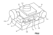
- FIG. 2 is an external perspective view showing the internal structure of the information input / output device.
- FIG. 3 is an external perspective view of the information input / output device with the upper half of the casing removed.
- 4A and 4B are diagrams showing a ring-type holder to which the casing of the information input / output device is mounted, FIG. 4A shows a state in which the ring-type holder and the casing are separated, and FIG. 4B shows a ring-type holder. Shows a state in which a housing is mounted.
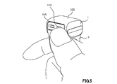
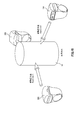
- FIG. 5 is an external perspective view showing a usage state of the information input / output device.
- FIG. 5 is an external perspective view showing a usage state of the information input / output device.
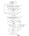
- FIG. 6 is a flowchart showing a procedure of information input / output control in the first input operation mode by the control unit in the information input / output device.
- FIG. 7 is a diagram illustrating an example of detection output signals of the sensors used for information input / output control in the first input operation mode.
- FIG. 8 is a diagram showing another example of the detection output signal of each sensor used for information input / output control in the first input operation mode.
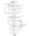
- FIG. 9 is a flowchart showing a procedure of information input / output control in the second input operation mode by the control unit in the information input / output device.
- FIG. 10 is a diagram illustrating an example of detection output signals of the sensors used for information input / output control in the second input operation mode.
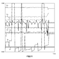
- FIG. 11 is a diagram showing another example of detection output signals of the sensors used for information input / output control in the second input operation mode.
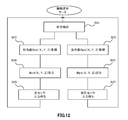
- FIG. 12 is a flowchart showing a procedure of information input / output control in the information presentation mode by the control unit in the information input / output device.
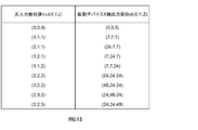
- FIG. 13 is a diagram illustrating an example of the contents of a correspondence table between a three-dimensional space value by an optical sensor input and an output value of a vibration device used in information input / output control in the information presentation mode.
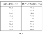
- FIG. 14 is a diagram illustrating an example of the contents of a correspondence table between a three-dimensional space value by an atmospheric pressure sensor input and an output value of a vibration device used in information input / output control in the information presentation mode.
- FIG. 15 is a diagram schematically illustrating an example of information input / output in a three-dimensional space in cooperation with the virtual reality system.
- the present invention is applied to, for example, an information input / output device 100 configured as shown in the block diagram of FIG.
- the information input / output device 100 is a device for inputting / outputting information in space in a wearable or mobile computer environment, and includes a portable housing 1, and includes a control unit 10 including a CPU, An optical sensor 11, an acceleration sensor 12, an angular velocity sensor 13, an orientation sensor 14, an atmospheric pressure sensor 15, a temperature sensor 16, a vibration device 17, a communication interface 18, a battery unit 19 that supplies power to the optical sensor 11, an acceleration sensor 12, an angular velocity sensor 13, an orientation sensor 14. Provided in the housing 1.
- the optical sensor 11 is an environment sensor that detects an environmental change in a three-dimensional space in which information is input / output by the information input / output device 100 as a change in received light amount in the usage state of the information input / output device 100.
- a detection output signal indicating the amount of received light in the space is supplied to the control unit 10.
- the acceleration sensor 12 is an environment sensor that detects an environmental change in the three-dimensional space as a change in acceleration in the usage state of the information input / output device 100, and detects and outputs a signal level corresponding to the acceleration in the three-dimensional space. A signal is supplied to the control unit 10.
- the angular velocity sensor 13 is an environment sensor that detects an environmental change in the three-dimensional space as a change in angular velocity in the usage state of the information input / output device 100, and controls the detection output signal indicating the angular velocity in the three-dimensional space. Supplied to the unit 10.
- the orientation sensor 14 is an environment sensor that detects an environmental change in the three-dimensional space as a change in orientation in the usage state of the information input / output device 100, and controls the detection output signal indicating the orientation in the three-dimensional space. Supplied to the unit 10. As this direction sensor 14, a geomagnetic sensor is used.
- the atmospheric pressure sensor 15 is an environmental sensor that detects an environmental change in the three-dimensional space as a change in atmospheric pressure in the usage state of the information input / output device 100, and controls the detection output signal indicating the atmospheric pressure in the three-dimensional space. Supplied to the unit 10.
- the temperature sensor 16 is an environment sensor that detects an environmental change in the three-dimensional space as a temperature change in the usage state of the information input / output device 100, and controls the detection output signal indicating the temperature in the three-dimensional space. Supplied to the unit 10.
- the vibration device 17 is controlled by the control unit 10 and generates an output signal generated based on input information acquired based on an environmental change in a three-dimensional space where information is input / output by the information input / output device 100. Output as vibration information.
- the communication interface 18 is provided for the control unit 10 to exchange information with an external electronic device.
- the communication method is not particularly limited.
- a wireless communication standard such as Bluetooth (registered trademark), Wi-Fi (registered trademark), ZigBee (registered trademark), or the like can be used.
- the information input / output device 100 is operated by the power supplied from the battery unit 19, and the information by the optical sensor 11, acceleration sensor 12, angular velocity sensor 13, azimuth sensor 14, atmospheric pressure sensor 15, and temperature sensor 16. Based on input information acquired as a detection output corresponding to an environmental change in a three-dimensional space where information is input / output by the input / output device 100, the control unit 10 outputs an output signal corresponding to the environmental change in the three-dimensional space. And the generated output signal is output from the vibration device 17 as vibration information.
- the power supply from the battery unit 19 can be turned on and off by operating the switch 19A.
- the control unit 10 the optical sensor 11, the acceleration sensor 12, the angular velocity sensor 13, the direction sensor 14, the atmospheric pressure sensor 15, the temperature sensor 16, the vibration device 17, the communication interface 18, and the like are as follows.
- the external perspective view of FIG. 2 the external perspective view of the information input / output device 100 in a state of being stacked on the battery unit 19 and having the upper half of the housing 1 removed is shown in FIG. Built in the housing 1.
- FIG. 4A and FIG. 4B are diagrams showing a ring type holder to which the casing of the information input / output device is mounted, FIG. 4A shows a state where the ring type holder and the casing are separated, and FIG. The state which mounted
- the information input / output device 100 is used by being attached to, for example, an index finger of a user via the ring type holder 2.
- control part 10 in this information input / output device 100 performs the information input / output control of the first input operation mode according to the procedure shown in the flowchart of FIG.
- control unit 10 performs non-contact information output control by the optical sensor 11.
- step S ⁇ b> 1 the control unit 10 detects the information input / output device 100 detected by the optical sensor 11 as first environment change information in a three-dimensional space in which information is input / output by the information input / output device 100.
- the detection output signal indicating the amount of received light in the three-dimensional space, that is, the light input absolute value (Vcd) data is acquired.
- the control unit 10 converts the first environment change information, that is, the light input absolute value (Vcd) data acquired in the process of step S1, into the light input relative value by the following conversion formula (formula 1).
- a process of converting into a quantity ( ⁇ Vcd) is performed.
- t is a unit time
- n is a measured natural number of the optical input absolute value
- control unit 10 determines whether or not the light input relative amount ( ⁇ Vcd) obtained in the process of step S2 has exceeded a threshold value Tcd for determining whether or not to enter the information input state. Processing to determine is performed.
- step S4 the control unit 10 determines that the determination result in step S3 is “YES”, that is, if the light input relative amount ( ⁇ Vcd) exceeds the threshold value Tcd, the second environment in the three-dimensional space.
- change information acceleration information indicated by a detection output signal from the acceleration sensor 12, angular velocity information indicated by a detection output signal from the angular velocity sensor 13, orientation information indicated by a detection output signal from the orientation sensor 14, and detection output signal from the pressure sensor 15.
- the pressure information indicated by, and the temperature information indicated by the detection output signal from the temperature sensor 16 are simultaneously acquired.
- step S3 If the determination result in step S3 is “NO”, that is, if the light input relative amount ( ⁇ Vcd) does not exceed the threshold value Tcd, the process returns to step S1, and the detection output signal from the optical sensor 11 is used. The process of obtaining the indicated optical input absolute value (Vcd) data is repeated.
- control unit 10 uses the information input / output device from a part or all of the second environment change information, that is, acceleration information, angular velocity information, azimuth information, atmospheric pressure information, and temperature information in the process of step S4. It is determined what state 100 is in the three-dimensional space.
- step S5 the control unit 10 indicates that the light input relative amount ( ⁇ Vcd) obtained in the process of step S2 is the threshold value as shown in FIG. If the information input / output device 100 does not move in the three-dimensional space exceeding Tcd, in the next step S6, the three-dimensional space value Vcd (0, 0, 0) is calculated from the acceleration information, angular velocity information, and azimuth information. ) And the input information is [Input 1].
- S AX is an X axis acceleration detection signal
- S AY is a Y axis acceleration detection signal
- S AZ is a Z axis acceleration detection signal
- S BX is an X axis angular velocity detection signal
- S BY is the angular velocity detection signal of the Z-axis
- S C is the light quantity detection signal
- S D is pressure detection signal
- S E is a temperature detection signal. Since the acceleration detection signals S AX , S AY , and S AZ are hardly changed, the information input / output device 100 has hardly moved in the three-dimensional space, but the light amount detection signal S Since C varies as shown in FIG. 7, it is determined that there is an input instruction, and the three-dimensional space value Vcd (X, Y, Z) by the optical sensor 11 is set to Vcd (0, 0, 0). The information is [Input 1].
- step S5 the control unit 10 indicates that the light input relative amount ( ⁇ Vcd) obtained in the process of step S2 is the threshold value as shown in FIG.
- the three-dimensional space value Vcd (X, Y, Z) is calculated from the acceleration information, angular velocity information, and direction information. )
- input information is [input 2].
- S AX is an X axis acceleration detection signal
- S AY is a Y axis acceleration detection signal
- S AZ is a Z axis acceleration detection signal
- S BX is an X axis angular velocity detection signal
- S BY is the angular velocity detection signal of the Y-axis
- S BZ is the angular velocity detection signal of the Z-axis
- S C is the light quantity detection signal
- S D is pressure detection signal
- S E is a temperature detection signal.
- the information input / output device 100 is moved in the three-dimensional space.
- the shows, the light quantity detection signal S C is, since the variation as shown in FIG. 8, it is determined that there is an input instruction, the three-dimensional space value by the optical sensor 11 Vcd (X, Y, Z ) and Vcd ( X1, Y1, Z1), and the input information is [input 2].
- the control unit 10 executes the command using the input information [input 1] as a stationary state command and the input information [input 2] as an operation state command. That is, the input information [input 1] is determined to be an optical sensor input instruction when there is no three-dimensional space movement of the information input / output device 100, and an optical sensor input corresponding process when there is no three-dimensional space movement is performed. On the other hand, the input information [input 2] is determined to be an optical sensor input instruction when there is a three-dimensional space movement of the information input / output device 100, and an optical sensor input corresponding process when there is a three-dimensional space movement is performed.
- the information input / output device 100 indicates the first environment change information for determining whether or not to input / output information by the detection output signal from the optical sensor 11.
- the control unit 10 uses the optical input absolute value (Vcd) data to perform input / output depending on whether the optical input relative value ( ⁇ Vcd) obtained by converting the optical input absolute value (Vcd) exceeds the threshold value Tcd. It is determined whether or not.
- the light input relative amount ( ⁇ Vcd) does not exceed the threshold value Tcd
- there is an input / output instruction when the light input relative amount ( ⁇ Vcd) exceeds the threshold value Tcd without entering the information input state.
- the second environmental change information that is, the acceleration information indicated by the detection output signal from the acceleration sensor 12, the angular velocity information indicated by the detection output signal from the angular velocity sensor 13, and the detection output signal from the direction sensor 14 are indicated.
- the information input / output device 100 when the user uses it by attaching it to, for example, the index finger of the user via the ring type holder 2, the light input absolute value is obtained by covering the light receiving unit 11A of the optical sensor 11 with a thumb, for example.
- An input / output instruction can be issued by changing the value (Vcd).
- the control unit 10 in the information input / output device 100 performs information input / output control in the second input operation mode, for example, according to the procedure shown in the flowchart of FIG.
- control unit 10 performs non-contact information output control by the atmospheric pressure sensor 15.
- step S ⁇ b> 11 the control unit 10 detects the information input / output device 100 detected by the atmospheric pressure sensor 15 as first environment change information in a three-dimensional space in which information is input / output by the information input / output device 100.
- the detection output signal indicating the atmospheric pressure in the three-dimensional space, that is, the atmospheric pressure absolute value (Vps) data is acquired.
- the control unit 10 converts the first environment change information, that is, the absolute pressure value (Vps) data acquired in the process of the above step S11, into the atmospheric pressure relative amount (equation 2) by the following conversion equation (equation 2). (Vps) is converted.
- t is a unit time
- m is a measured natural number of the atmospheric pressure input absolute value.
- control unit 10 determines whether or not the atmospheric pressure relative amount ( ⁇ Vps) obtained in the process of step S12 has exceeded a threshold value Tps for determining whether or not to enter the information input state. Perform the process.
- step S14 the control unit 10 determines that the determination result in step S13 is "YES", that is, if the atmospheric pressure relative amount ( ⁇ Vps) exceeds the threshold value Tps, the second environmental change in the three-dimensional space.
- acceleration information indicated by a detection output signal from the acceleration sensor 12 angular velocity information indicated by a detection output signal from the angular velocity sensor 13, orientation information indicated by a detection output signal from the orientation sensor 14, and detection output signal from the atmospheric pressure sensor 15.
- a process of simultaneously obtaining the atmospheric pressure information indicated and the temperature information indicated by the detection output signal from the temperature sensor 16 is performed.
- step S13 If the determination result in step S13 is “NO”, that is, if the light input relative amount ( ⁇ Vps) does not exceed the threshold value Tps, the process returns to step S11 and the detection output signal from the atmospheric pressure sensor 15 is used. Repeats the process of obtaining the indicated absolute pressure (Vcd) data
- control unit 10 uses the information input / output device from a part or all of the second environment change information, that is, acceleration information, angular velocity information, azimuth information, atmospheric pressure information, and temperature information in the process of step S14. It is determined what state 100 is in the three-dimensional space.
- step S15 for example, as shown in FIG. 10, the control unit 10 indicates that the relative pressure ( ⁇ Vps) obtained in the process of step S12 is the threshold value Tps. If the information input / output device 100 has not moved greatly in the three-dimensional space, the three-dimensional space value Vps (0, 0, 0) is calculated from the acceleration information, angular velocity information, and direction information in the next step S16. ) And the input information is [Input 3].
- S AX is an X axis acceleration detection signal
- S AY is a Y axis acceleration detection signal
- S AZ is a Z axis acceleration detection signal
- S BX is an X axis angular velocity detection signal
- S BY is the angular velocity detection signal of the Z-axis
- S C is the light quantity detection signal
- S D is pressure detection signal
- S E is a temperature detection signal. Since the acceleration detection signals S AX , S AY , and S AZ hardly change, it indicates that the information input / output device 100 has hardly moved in the three-dimensional space, but the atmospheric pressure detection signal S Since D varies as shown in FIG. 10, it is determined that there is an input instruction, and the three-dimensional space value Vps (X, Y, Z) by the atmospheric pressure sensor 15 is set to Vps (0, 0, 0). The information is [Input 3].
- step S15 for example, as shown in FIG. 11, the detection output signal of each sensor, the control unit 10 determines that the atmospheric pressure relative amount ( ⁇ Vps) obtained in the process of step S12 is the threshold value Tps. If the information input / output device 100 is moved greatly in the three-dimensional space, in the next step S17, the three-dimensional space value Vps (X, Y, Z) is calculated from the acceleration information, angular velocity information, and azimuth information. ) As an operator, and input information is [input 4].
- S AX is an X axis acceleration detection signal
- S AY is a Y axis acceleration detection signal
- S AZ is a Z axis acceleration detection signal
- S BX is an X axis angular velocity detection signal
- S BY is the angular velocity detection signal of the Y-axis
- S BZ is the angular velocity detection signal of the Z-axis
- S C is the light quantity detection signal
- S D is pressure detection signal
- S E is a temperature detection signal.
- the information input / output device 100 is moved in the three-dimensional space. Since the atmospheric pressure detection signal SD fluctuates as shown in FIG. 11, it is determined that there is an input instruction, and the three-dimensional space value Vps (X, Y, Z) by the atmospheric pressure sensor 15 is expressed as Vps ( X2, Y2, Z2), and the input information is [input 4].
- the control unit 10 executes the command using the input information [input 3] as a stationary state command and the input information [input 4] as an operation state command. That is, the input information [input 3] is determined to be a pressure sensor input instruction when there is no three-dimensional space movement of the information input / output device 100, and pressure sensor input corresponding processing when there is no three-dimensional space movement is performed. On the other hand, the input information [input 4] is determined to be an atmospheric pressure sensor input instruction when there is a three-dimensional space movement of the information input / output device 100, and an atmospheric pressure sensor input corresponding process when there is a three-dimensional space movement is performed.
- the information input / output device 100 indicates the first environment change information for determining whether or not to input / output information by the detection output signal from the atmospheric pressure sensor 15. Whether or not to perform input / output force based on whether or not the relative atmospheric pressure ( ⁇ Vps) obtained by converting the absolute atmospheric pressure (Vps) exceeds the threshold Tps using the absolute atmospheric pressure (Vps) data. Is judged. If the atmospheric pressure relative amount ( ⁇ Vps) does not exceed the threshold value Tps, even if the information input / output device 100 is largely moved in the three-dimensional space, it is not regarded as an input / output instruction, and the light input relative amount.
- the absolute pressure value (Vcd) varies depending on the height position of the information input / output device 100. Therefore, it is possible to give input / output instructions in cooperation with an operation such as raising a raised hand or moving from the first floor to the second floor.
- the control unit 10 acquires the posture information in the use state of the information input / output device 100 from the detection output signal indicating the angular velocity in the three-dimensional space obtained by the angular velocity sensor 13. That is, the angular velocity sensor 13 functions as a posture sensor for acquiring posture information in the usage state of the information input / output device 100.
- the control unit 10 acquires position information in the use state of the information input / output device 100 from the detection output signal indicating the acceleration speed in the three-dimensional space obtained by the acceleration sensor 12. That is, the acceleration sensor 12 functions as a position sensor for acquiring position information in the usage state of the information input / output device 100.
- control unit 10 performs information input / output control in the information presentation mode, for example, according to the procedure shown in the flowchart of FIG.
- step S21 the control unit 10 performs input information [input 1], [input 2], and the second input operation based on the detection of the optical sensor 11 executed in the first input operation mode.
- a process of detecting a command based on input information [input 3] and [input 4] based on detection of the atmospheric pressure sensor 15 executed in the mode is performed.
- the control unit 10 determines the three-dimensional space value Vcd (X, Y, Z) and the output value Bcd (X, Y, Z) of the vibration device 17 as shown in FIG. Referring to the correspondence table, the process of acquiring the output value Bcd (X, Y, Z) of the vibration device 17 is performed.
- the control unit 10 determines, for example, the three-dimensional space value Vps (X, Y, Z) and the output value Bps (X, Y, Z) of the vibration device 17 by the atmospheric pressure sensor input as shown in FIG. Referring to the correspondence table, a process for obtaining the output value Bps (X, Y, Z) of the vibrating device 17 is performed.
- control unit 10 gives the output value Bcd (X, Y, Z) corresponding to the acquired three-dimensional space value Vcd (X, Y, Z) to the vibrating device 17 to vibrate.
- the control unit 10 gives the output value Bps (X, Y, Z) corresponding to the acquired three-dimensional space value Vps (X, Y, Z) to the vibration device 17 to vibrate.
- the control unit 10 waits for an input from the next optical sensor 11 in the next step S26, and the first input described above.
- the process returns to the step S21 and the vibration is performed according to the correspondence table shown in FIG. The output process for vibrating the device 17 is repeatedly controlled.
- the control unit 10 waits for an input from the next atmospheric pressure sensor 15 in the next step S27, and the second input described above.
- the process returns to the step S21 and the vibration is performed according to the correspondence table shown in FIG. The output process for vibrating the device 17 is repeatedly controlled.
- the first sensor that detects the first environmental change in the three-dimensional space, that is, the optical sensor 11 or the atmospheric pressure sensor.
- a second detection unit for detecting a second environmental change in the three-dimensional space when the detection output obtained by the first sensor exceeds the threshold value. Acceleration information indicated by the detection output signal from the acceleration sensor 12, angular velocity information indicated by the detection output signal from the angular velocity sensor 13, azimuth information indicated by the detection output signal from the azimuth sensor 14, and detection by the atmospheric pressure sensor 15.
- the command is executed with all the input information [input 1], [input 2], [input 3], and [input 4], and the second environment change in the three-dimensional space is performed based on the input information.
- the control unit 10 performs control to generate an output signal and output the generated output signal as vibration information from an information output unit including at least one vibration device 17.
- the information input / output device 100 it is determined whether or not to enter the information input state based on whether or not the detection output of the first environment change in the three-dimensional space exceeds the threshold, and the first environment
- the change detection output exceeds a threshold
- the second environment change in the three-dimensional space is detected as input information, and the vibration information corresponding to the second environment change in the three-dimensional space is output, so that the wearable Alternatively, information can be input and output easily and reliably in space in a mobile computer environment.
- the information input / output device 100 includes three pieces of the vibration device 17 that are three-dimensionally arranged so that the three axes (X axis, Y axis, Z axis) direction of the three-dimensional space and the vibration plane are orthogonal to each other.
- the control unit 10 determines whether or not to enter the information input state based on whether or not the detection output of the first environmental change in the three-dimensional space exceeds a threshold value. When the detection output of the first environmental change exceeds a threshold, the second environmental change in the three-dimensional space is detected as input information, and the three-dimensional according to the second environmental change in the three-dimensional space
- the vibration information is output from the three vibration devices 17X, 17Y, and 17Z arranged three-dimensionally.
- control unit 10 is executed in the input information [input 1], [input 2], and the second input operation mode based on the detection output of the optical sensor 11 executed in the first input operation mode.
- three-dimensional vibration information is obtained from the three vibration devices 17X, 17Y, and 17Z arranged in three dimensions. Output.
- the control unit 10 in the portable information input / output device 100 has a function of exchanging information with a portable terminal or the like via the communication interface 18, and the three-dimensional space value Vcd (X, Y, Z) and the output value Bcd (X, Y, Z) of the vibration device 17, and the three-dimensional space value Vps (X, Y, Z) and the output value of the vibration device 17 by the pressure sensor input.
- a correspondence table with Bps (X, Y, Z) is acquired and stored in a memory, or input information [input 1], [input 2], [input 3], and [input 4] are transmitted to a portable terminal or the like.
- the portable information input / output device 100 is attached to the user's finger via the ring-type holder 2, but via small-sized holders such as a bracelet type, a stick type, and a pencil type.
- the outer shape of the housing 1 may be various small and portable shapes such as a ring type, a bracelet type, a stick type, and a pencil type.
Landscapes
- Engineering & Computer Science (AREA)
- General Engineering & Computer Science (AREA)
- Theoretical Computer Science (AREA)
- Human Computer Interaction (AREA)
- Physics & Mathematics (AREA)
- General Physics & Mathematics (AREA)
- User Interface Of Digital Computer (AREA)
- Position Input By Displaying (AREA)
Abstract
Description
場合に、三次元空間における第2の環境変化を入力情報として検出し、上記三次元空間における第2の環境変化に応じた振動情報を出力させる。
ただし、tは単位時間、nは光入力絶対値の測定自然数である。
ただし、tは単位時間、mは気圧入力絶対値の測定自然数である。
Claims (9)
- 携帯可能な筐体を具備する携帯型情報入出力装置であって、
三次元空間における第1の環境変化を検出する第1のセンサと、
上記三次元空間における第2の環境変化を検出する第2のセンサと、
少なくとも1つの振動デバイスからなる情報出力手段と、
上記第1のセンサにより取得される検出出力が閾値を超えたか否かを判定し、上記第1のセンサにより取得される検出出力が閾値を超えた場合に、上記第2のセンサにより検出される上記第2の環境変化を入力情報として取得し、取得した上記入力情報に基づいて、上記三次元空間における第2の環境変化に応じた出力信号を生成し、生成した出力信号を情報出力手段から振動情報として出力させる制御を行う制御手段とを上記筐体内に備える携帯型情報入出力装置。 - 上記第1のセンサは、上記三次元空間における第1の環境変化を受光量の変化として検出する光センサであり、
上記制御手段は、上記光センサにより上記三次元空間における受光量の変化として検出される上記第1の環境変化に基づいて、情報入力状態とするか否かを判断して、上記第2のセンサにより検出される上記第2の環境変化を入力情報として取得することを特徴とする請求項1記載の携帯型情報入出力装置。 - 上記第1のセンサは、上記三次元空間における第1の環境変化を気圧の変化として検出する圧力センサであり、
上記制御手段は、上記圧力センサにより上記三次元空間における気圧の変化として検出される上記第1の環境変化に基づいて、情報入力状態とするか否かを判断して、上記第2のセンサにより検出される上記第2の環境変化を入力情報として取得することを特徴とする請求項1記載の携帯型情報入出力装置。 - 上記制御手段は、上記第1のセンサによる検出出力として取得される絶対数値データ又は絶対値データを相対量に変換して閾値を超えたか否かを判定することを特徴とする請求項2又は3の何れか1項記載の携帯型情報入出力装置。
- 上記第2のセンサは、上記三次元空間における第2の環境変化として上記三次元空間における位置、姿勢、方位の1つ以上の変化を検出する三次元センサであり、
上記制御手段は、上記第1のセンサにより取得される検出出力が閾値を超えた場合に、上記第2のセンサにより上記三次元空間における位置、姿勢、方位の1つ以上の変化として検出される上記第2の環境変化を入力情報として取得し、上記三次元空間における位置、姿勢、方位の1つ以上の変化に応じた出力信号を上記情報出力手段から振動情報として出力させる制御を行うことを特徴とする請求項1乃至3の何れか1項記載の携帯型情報入出力装置。 - 上記情報出力手段は、三次元配置された複数個の振動デバイスからなり、
上記制御手段は、上記第1のセンサにより取得される検出出力が閾値を超えた場合に、上記第2のセンサにより検出される上記第2の環境変化を入力情報に基づいて、上記三次元空間における位置、姿勢、方位の1つ以上の変化に応じた出力信号を上記情報出力手段から三次元の振動情報として出力させる制御を行うことを特徴とする請求項5記載の携帯型情報入出力装置。 - 上記三次元センサは、加速度センサ、角速度センサ、方位センサの内の何れか1種類又は複数種類のセンサを備えることを特徴とする請求項6記載の携帯型情報入出力装置。
- 上記筐体は指輪型ホルダの装着部に着脱自在に装着され、上記指輪型ホルダを介して指に装着されることを特徴とする請求項1記載の情報入出力装置。
- 携帯可能な筐体を具備する携帯型情報入出力装置による情報入出力方法であって、
三次元空間における第1の環境変化を検出する第1のセンサによる検出出力が閾値を超えたか否かを判定し、
上記第1のセンサにより取得される検出出力が閾値を超えた場合に、第2のセンサにより検出される上記三次元空間における第2の環境変化を入力情報として取得し、
取得した上記入力情報に基づいて、上記三次元空間における第2の環境変化に応じた出力信号を生成し、
生成した出力信号を少なくとも1つの振動デバイスからなる情報出力手段から振動情報として出力させることを特徴とする情報入出力方法。
Priority Applications (1)
| Application Number | Priority Date | Filing Date | Title |
|---|---|---|---|
| US15/120,042 US10082885B2 (en) | 2014-03-13 | 2015-02-04 | Information input and output apparatus and information input and output method |
Applications Claiming Priority (2)
| Application Number | Priority Date | Filing Date | Title |
|---|---|---|---|
| JP2014049701A JP6270557B2 (ja) | 2014-03-13 | 2014-03-13 | 情報入出力装置及び情報入出力方法 |
| JP2014-049701 | 2014-03-13 |
Publications (1)
| Publication Number | Publication Date |
|---|---|
| WO2015137014A1 true WO2015137014A1 (ja) | 2015-09-17 |
Family
ID=54071466
Family Applications (1)
| Application Number | Title | Priority Date | Filing Date |
|---|---|---|---|
| PCT/JP2015/053073 WO2015137014A1 (ja) | 2014-03-13 | 2015-02-04 | 情報入出力装置及び情報入出力方法 |
Country Status (3)
| Country | Link |
|---|---|
| US (1) | US10082885B2 (ja) |
| JP (1) | JP6270557B2 (ja) |
| WO (1) | WO2015137014A1 (ja) |
Families Citing this family (4)
| Publication number | Priority date | Publication date | Assignee | Title |
|---|---|---|---|---|
| JP6881159B2 (ja) * | 2016-12-28 | 2021-06-02 | 花王株式会社 | 感触評価装置 |
| JP6958119B2 (ja) * | 2017-08-29 | 2021-11-02 | 花王株式会社 | 感触評価装置 |
| CN110278230A (zh) * | 2018-03-16 | 2019-09-24 | 阿里巴巴集团控股有限公司 | 数据处理方法、客户端、服务器及存储介质 |
| JP7530338B2 (ja) | 2021-07-08 | 2024-08-07 | マクセル株式会社 | 指の動きを検出するセンサ、センサ装着体およびセンサアセンブリ |
Citations (4)
| Publication number | Priority date | Publication date | Assignee | Title |
|---|---|---|---|---|
| JPH11508382A (ja) * | 1995-04-26 | 1999-07-21 | インターバル リサーチ コーポレイション | 状況を感知する汎用インタフェース装置 |
| JP2010134955A (ja) * | 1995-11-30 | 2010-06-17 | Immersion Corp | 触覚感覚を与えるための装置、システム、及び方法 |
| JP2013025664A (ja) * | 2011-07-25 | 2013-02-04 | Sony Corp | 入力装置、入力方法及び制御システム |
| WO2013022712A2 (en) * | 2011-08-05 | 2013-02-14 | Qualcomm Incorporated | Gesture detection using proximity or light sensors |
Family Cites Families (10)
| Publication number | Priority date | Publication date | Assignee | Title |
|---|---|---|---|---|
| JP2500283B2 (ja) | 1992-04-13 | 1996-05-29 | 株式会社高度映像技術研究所 | 仮想空間キ―ボ―ド装置 |
| JP3857504B2 (ja) | 1993-05-21 | 2006-12-13 | ソニー株式会社 | 入力装置、制御システム |
| JPH0712194A (ja) * | 1993-06-21 | 1995-01-17 | Mazda Motor Corp | トロイダル型無段変速機 |
| JP2001312356A (ja) | 2000-04-28 | 2001-11-09 | Tomohiro Kuroda | 身体を利用する画像入力インタフェースを備えた一体型装着型計算機 |
| US7020508B2 (en) * | 2002-08-22 | 2006-03-28 | Bodymedia, Inc. | Apparatus for detecting human physiological and contextual information |
| JP4930160B2 (ja) * | 2007-04-04 | 2012-05-16 | セイコーエプソン株式会社 | 水泳距離計測装置 |
| CA2699844A1 (en) * | 2007-08-19 | 2009-02-26 | Ringbow Ltd. | Finger-worn devices and related methods of use |
| JP2010204724A (ja) * | 2009-02-27 | 2010-09-16 | Denso Corp | 入力システム及び電気機器 |
| JP5755549B2 (ja) * | 2011-10-26 | 2015-07-29 | パイオニア株式会社 | ソース機器およびこれを備えた再生システム |
| JP5613314B1 (ja) * | 2013-11-14 | 2014-10-22 | Jfeシステムズ株式会社 | ジェスチャー検出装置、ジェスチャー検出プログラム、ジェスチャー認識装置およびジェスチャー認識プログラム |
-
2014
- 2014-03-13 JP JP2014049701A patent/JP6270557B2/ja not_active Expired - Fee Related
-
2015
- 2015-02-04 WO PCT/JP2015/053073 patent/WO2015137014A1/ja active Application Filing
- 2015-02-04 US US15/120,042 patent/US10082885B2/en not_active Expired - Fee Related
Patent Citations (4)
| Publication number | Priority date | Publication date | Assignee | Title |
|---|---|---|---|---|
| JPH11508382A (ja) * | 1995-04-26 | 1999-07-21 | インターバル リサーチ コーポレイション | 状況を感知する汎用インタフェース装置 |
| JP2010134955A (ja) * | 1995-11-30 | 2010-06-17 | Immersion Corp | 触覚感覚を与えるための装置、システム、及び方法 |
| JP2013025664A (ja) * | 2011-07-25 | 2013-02-04 | Sony Corp | 入力装置、入力方法及び制御システム |
| WO2013022712A2 (en) * | 2011-08-05 | 2013-02-14 | Qualcomm Incorporated | Gesture detection using proximity or light sensors |
Also Published As
| Publication number | Publication date |
|---|---|
| JP6270557B2 (ja) | 2018-01-31 |
| US10082885B2 (en) | 2018-09-25 |
| JP2015176176A (ja) | 2015-10-05 |
| US20170068333A1 (en) | 2017-03-09 |
Similar Documents
| Publication | Publication Date | Title |
|---|---|---|
| KR101666096B1 (ko) | 강화된 제스처 기반 상호작용 시스템 및 방법 | |
| EP2975497B1 (en) | Terminal device, terminal device control method, and program | |
| KR100744902B1 (ko) | 휴대 무선 조작기 | |
| JP5392093B2 (ja) | 入力装置、制御装置、制御システム、制御方法及びハンドヘルド装置 | |
| JP2012508408A (ja) | 空中での指の動きを通じて制御されるマウス | |
| US20120235906A1 (en) | Apparatus and method for inputting information based on events | |
| JPWO2009072475A1 (ja) | 入力装置、制御装置、制御システム、ハンドヘルド装置及び制御方法 | |
| JP2006511862A (ja) | 非接触型入力装置 | |
| WO2015137014A1 (ja) | 情報入出力装置及び情報入出力方法 | |
| US20110310013A1 (en) | Interface apparatus and method for contact-free space input/output | |
| TWM518361U (zh) | 指戴式輸入裝置 | |
| KR20160143428A (ko) | 펜 단말기 및 그 제어방법 | |
| US20170199586A1 (en) | Gesture control method for interacting with a mobile or wearable device utilizing novel approach to formatting and interpreting orientation data | |
| US8779904B2 (en) | Multimode remote controller comprising an accelerometer, a gyroscope, a capacitive pressure transducer, and a touch pad | |
| KR101211808B1 (ko) | 동작인식장치 및 동작인식방법 | |
| US20150002486A1 (en) | Multifunctional pencil input peripheral computer controller | |
| JP2011065512A (ja) | 情報処理システム、情報処理プログラム、操作認識システム、および操作認識プログラム、 | |
| KR20150093270A (ko) | 모션 인터페이스 디바이스 | |
| JP2009187353A (ja) | 入力装置 | |
| KR101473469B1 (ko) | 리모콘 장치 및 전자 기기의 동작 제어 방법 | |
| KR20010110615A (ko) | 피부의 움직임을 감지하여 작동되는 정보입력장치와 이를이용한 이동정보처리장치와 컴퓨터와 이동통신기기 | |
| WO2013032410A1 (en) | Multifunctional pencil input peripheral computer controller | |
| Sekar et al. | Wearable Virtual Keyboard for Visually Impaired Person | |
| US20230116966A1 (en) | A dual peripheral device | |
| Singh et al. | Glove Mouse: A Gesture Controlled Wireless Computer Mouse |
Legal Events
| Date | Code | Title | Description |
|---|---|---|---|
| 121 | Ep: the epo has been informed by wipo that ep was designated in this application |
Ref document number: 15761271 Country of ref document: EP Kind code of ref document: A1 |
|
| DPE1 | Request for preliminary examination filed after expiration of 19th month from priority date (pct application filed from 20040101) | ||
| WWE | Wipo information: entry into national phase |
Ref document number: 15120042 Country of ref document: US |
|
| NENP | Non-entry into the national phase |
Ref country code: DE |
|
| 32PN | Ep: public notification in the ep bulletin as address of the adressee cannot be established |
Free format text: NOTING OF LOSS OF RIGHTS PURSUANT TO RULE 112(1) EPC , EPO FORM 1205A DATED 13-12-16 |
|
| 122 | Ep: pct application non-entry in european phase |
Ref document number: 15761271 Country of ref document: EP Kind code of ref document: A1 |