WO2015136883A1 - 液体噴射装置および手術機器 - Google Patents
液体噴射装置および手術機器 Download PDFInfo
- Publication number
- WO2015136883A1 WO2015136883A1 PCT/JP2015/001084 JP2015001084W WO2015136883A1 WO 2015136883 A1 WO2015136883 A1 WO 2015136883A1 JP 2015001084 W JP2015001084 W JP 2015001084W WO 2015136883 A1 WO2015136883 A1 WO 2015136883A1
- Authority
- WO
- WIPO (PCT)
- Prior art keywords
- liquid
- ejecting apparatus
- supply
- suction
- nozzle
- Prior art date
Links
Images


Classifications
-
- A—HUMAN NECESSITIES
- A61—MEDICAL OR VETERINARY SCIENCE; HYGIENE
- A61B—DIAGNOSIS; SURGERY; IDENTIFICATION
- A61B17/00—Surgical instruments, devices or methods, e.g. tourniquets
- A61B17/32—Surgical cutting instruments
- A61B17/3203—Fluid jet cutting instruments
-
- F—MECHANICAL ENGINEERING; LIGHTING; HEATING; WEAPONS; BLASTING
- F04—POSITIVE - DISPLACEMENT MACHINES FOR LIQUIDS; PUMPS FOR LIQUIDS OR ELASTIC FLUIDS
- F04B—POSITIVE-DISPLACEMENT MACHINES FOR LIQUIDS; PUMPS
- F04B43/00—Machines, pumps, or pumping installations having flexible working members
- F04B43/02—Machines, pumps, or pumping installations having flexible working members having plate-like flexible members, e.g. diaphragms
- F04B43/04—Pumps having electric drive
- F04B43/043—Micropumps
-
- A—HUMAN NECESSITIES
- A61—MEDICAL OR VETERINARY SCIENCE; HYGIENE
- A61B—DIAGNOSIS; SURGERY; IDENTIFICATION
- A61B17/00—Surgical instruments, devices or methods, e.g. tourniquets
- A61B2017/00017—Electrical control of surgical instruments
- A61B2017/00137—Details of operation mode
- A61B2017/00154—Details of operation mode pulsed
-
- A—HUMAN NECESSITIES
- A61—MEDICAL OR VETERINARY SCIENCE; HYGIENE
- A61B—DIAGNOSIS; SURGERY; IDENTIFICATION
- A61B2217/00—General characteristics of surgical instruments
- A61B2217/002—Auxiliary appliance
- A61B2217/005—Auxiliary appliance with suction drainage system
Definitions
- the present invention relates to a liquid ejecting apparatus and a surgical instrument.
- Patent Document 1 describes a liquid ejecting apparatus.
- the liquid ejecting apparatus increases or decreases the volume of the fluid chamber to which a liquid such as physiological saline is supplied by driving the piezoelectric element.
- a pulse flow pulse flow
- the liquid ejecting apparatus ejects a pulse flow such as physiological saline from the ejection tube.
- the liquid ejecting apparatus is used as, for example, a medical scalpel, and can eject or pulverize a living body by ejecting a pulse flow such as physiological saline toward the living body.
- the kinetic energy of the pulse flow is added to the part of the living body hit by the pulse flow. Then, the droplets including living tissue such as excised or crushed cells move vigorously. As a result, living tissue such as cells that have been excised or crushed, and the injected pulse flow scatter and contaminate the surgical field. Therefore, there has been a demand for a liquid ejecting apparatus that suppresses scattering of living tissue such as cells excised or crushed by the ejected pulse flow.
- the present invention has been made to solve the above-described problems, and can be realized as the following forms or application examples.
- the liquid ejecting apparatus is a liquid ejecting apparatus that ejects the first liquid in a pulse form from the liquid ejecting opening of the ejecting pipe, and the second liquid is supplied from the supply pipe to the vicinity of the liquid ejecting opening.
- a second liquid supply means for supplying is provided.
- the first liquid is ejected in a pulse form from the liquid ejection opening of the ejection tube.
- the pulse shape means a fluid flow (pulsation) in which the fluid flowing direction is constant and the flow rate or flow velocity of the fluid is periodically or irregularly changed.
- the pulse flow includes an intermittent flow in which the flow and stop of the fluid are repeated.
- the pulse flow is not necessarily an intermittent flow. That is, ejecting the first liquid in a pulsed manner or ejecting a pulse flow of the first liquid means ejecting the first liquid with periodic or irregular fluctuations in flow rate or flow velocity. .
- a living tissue such as a cell is excised or crushed at a place where the pulse flow is applied.
- the liquid ejection opening nozzle
- the liquid ejection opening nozzle tip
- the second liquid water column
- the liquid by the second liquid A wall water wall
- the droplets containing the living tissue such as the excised or crushed cells are decelerated by the second liquid.
- the second liquid can be supplied uniformly from around the liquid injection opening.
- the liquid ejecting apparatus easily forms a liquid wall (water wall) of the second liquid around the liquid ejecting opening. Accordingly, it is possible to prevent the living tissue cut or crushed by the ejected first liquid or the liquid containing the ejected first liquid from scattering beyond the second liquid around the liquid ejection opening. Can do.
- the direction in which the supply pipe supplies the second liquid can be made to follow the direction in which the liquid ejection opening ejects the first liquid.
- the ejection pipe since the ejection pipe is inserted into the suction pipe, the liquid accumulated in the liquid ejection opening can be evenly sucked.
- the liquid ejection opening (nozzle tip) is immersed in the second liquid relatively evenly (water column), or a liquid wall (water wall) by the second liquid is formed around the liquid ejection opening.
- the suction pipe sucks the excessive second liquid located around the liquid ejection opening relatively evenly. Therefore, since the second liquid is arranged evenly around the liquid ejection opening, it is possible to suppress scattering of the ejected liquid.
- a liquid chamber that generates a pulse flow in the first liquid by changing a volume
- a volume changing unit that changes a change amount of the volume of the liquid chamber
- the liquid chamber Control means for controlling the supply amount of the second liquid supplied from the second liquid supply means on the basis of the volume change amount of the second liquid supply means.
- the flow rate of the pulse flow is high and the amount of the first liquid to be ejected increases, so that the splatter also increases.
- the second liquid supplied from the second liquid supply means is increased. Accordingly, it is possible to prevent the living tissue cut or crushed by the ejected first liquid or the liquid containing the ejected first liquid from being scattered beyond the second liquid around the liquid ejection opening. be able to.
- the change amount of the volume of the liquid chamber is small, the flow rate of the pulse flow is slow and the amount of the first liquid to be ejected is reduced, so that the splatter is also reduced. For this reason, even if it reduces the 2nd liquid supplied from a 2nd liquid supply means, scattering can be suppressed. As a result, the consumption amount of the second liquid can be reduced.
- the liquid ejecting apparatus includes a control unit that controls the supply amount of the second liquid.
- the control means increases the supply amount of the second liquid supplied from the second liquid supply means, it is possible to suppress the scattering of the first liquid.
- the liquid ejecting apparatus includes a control unit that controls the supply amount of the second liquid.
- the control means suppresses scattering by reducing the supply amount of the second liquid supplied from the second liquid supply means. Therefore, the consumption amount of the second liquid can be reduced.
- the liquid ejecting apparatus includes a switch for switching between ejection and non-ejection of the first liquid, and when the first liquid is ejected, the second liquid supply unit includes the switch When the second liquid is supplied and the ejection of the first liquid is stopped, the second liquid supply means includes a control means for performing control so as not to supply the second liquid. To do.
- the second liquid when the ejection of the first liquid is stopped, the second liquid is not supplied from the second liquid supply means. Therefore, the second liquid is not wastefully supplied when the first liquid is not ejected. Therefore, the consumption amount of the second liquid can be reduced.
- the liquid ejecting apparatus includes a distance detecting unit that detects a distance from the liquid ejecting opening to an object in a direction in which the first liquid is ejected, and the control unit includes the distance detecting unit.
- the distance detected from the second liquid is shorter than a predetermined distance, control is performed so that the second liquid is supplied from the second liquid supply means.
- the distance detection unit detects the distance between the liquid ejection opening and the object.
- the control means supplies the second liquid from the second liquid supply means when the distance detected from the distance detection means is shorter than the predetermined distance.
- the liquid ejection opening is close to the object, the liquid ejection opening (nozzle tip) is immersed in the second liquid (water column), or the liquid wall (water wall) of the second liquid ejects the liquid. It is easy to form around the opening (nozzle tip).
- the second liquid supplied from the second liquid supply means suppresses the scattering of the living tissue excised or crushed by the ejected first liquid and the liquid containing the ejected first liquid. it can. Since the control means supplies the second liquid when there is an effect of the second liquid, the consumption amount of the second liquid can be reduced.
- the liquid ejecting apparatus includes distance detecting means for detecting a distance from the liquid ejecting opening to an object in a direction in which the first liquid is ejected, and the control means includes the distance Control is performed to stop the supply of the second liquid from the second liquid supply means when the distance detected from the detection means is longer than a predetermined distance.
- the liquid ejection opening when the liquid ejection opening is far from the object, the liquid ejection opening (nozzle tip) is immersed in the second liquid (water column), or the liquid by the second liquid It is difficult for a wall (water wall) to be formed around the liquid ejection opening. Since the supply of the liquid is stopped according to the distance, the second liquid is not wasted. Since the control means supplies the second liquid when there is an effect of the second liquid, the consumption amount of the second liquid can be reduced. In addition, when the liquid ejection opening is far from the object, in addition to stopping the supply of the second liquid, a voice or the like is sent to the user of the liquid ejection device that the supply of the second liquid is stopped.
- the ejection of the first liquid may be stopped. Furthermore, when the supply of the first liquid is stopped, the user of the liquid ejecting apparatus may be notified by voice or the like that the supply of the first liquid has been stopped.
- the second liquid has a surface tension larger than that of the first liquid.
- the second liquid has a larger surface tension than the first liquid. For this reason, the cohesion force of the second liquid is improved at the liquid ejection opening, and the liquid ejection opening is immersed in the second liquid (water column) or the liquid wall (water wall) by the second liquid. Is easily formed around the liquid ejection opening. As a result, it is possible to easily suppress scattering of the ejected first liquid.
- the second liquid supply unit supplies the first liquid to the vicinity of the liquid ejecting opening.
- the first liquid is ejected from the liquid ejection opening, and the first liquid is supplied from the supply pipe. Therefore, it is not necessary to prepare the first liquid and the second liquid separately. As a result, since the container for the second liquid is not necessary, the liquid ejecting apparatus can be made small.
- a sum of a flow rate of the first liquid ejected from the liquid ejecting opening and a flow rate of the second liquid supplied from the second liquid supply unit is the liquid.
- An adjustment means is provided for adjusting a flow rate of at least one of the second liquid and the sucked liquid so as to be larger than a flow rate of the liquid sucked from the suction opening.
- the adjusting means adjusts the flow rates of the first liquid, the second liquid, and the sucked liquid. If the sum of the flow rate of the first liquid ejected from the liquid ejection opening and the flow rate of the second liquid supplied from the second liquid supply means is larger than the flow rate of the liquid sucked from the liquid suction opening, the liquid A state where the ejection opening (nozzle tip) is immersed in the second liquid (water column) or a liquid wall (water wall) due to the second liquid is easily formed around the liquid ejection opening. As a result, since the suction amount and the supply amount of the second liquid are adjusted, a water column or a water wall can be easily formed.
- the supply flow rate of the second liquid supplied from the second liquid supply unit is 5 ml / min or more.
- the supply flow rate of the second liquid supplied from the second liquid supply means is 5 ml / min or more.
- the liquid ejection opening (nozzle tip) is immersed in the second liquid (Water column) or a liquid wall (water wall) of the second liquid can be easily formed around the liquid ejection opening (nozzle tip). Therefore, scattering of the first liquid to be ejected and living cells can be suppressed.
- a surgical instrument according to this application example comprising the liquid ejecting apparatus according to any one of the above, wherein the first liquid is ejected to perform a surgical treatment on a living tissue.
- the liquid ejecting apparatus is used for the surgical instrument. Therefore, it is possible to suppress scattering of a living tissue that has been excised or crushed by the ejected first liquid or a liquid that includes the ejected first liquid. As a result, it is possible to perform surgical procedures (incision, excision, crushing, etc.) while preventing living tissue that has been excised or crushed, and liquids containing the ejected first liquid from splashing and contaminating the surgical field. it can.
- FIG. 4A is a block diagram illustrating a configuration of a liquid ejecting apparatus according to the first embodiment
- FIG. 5B is a partial schematic side view illustrating a structure of a nozzle of the liquid ejecting apparatus.
- (A) And (b) is a schematic diagram for demonstrating the behavior of the liquid in a nozzle.
- (A) is a schematic cross-sectional view showing the internal configuration of the pulsation imparting section
- (b) is a graph showing the transition of the volume of the liquid chamber
- (c) is the relationship between the second liquid supply amount and the volume change amount of the liquid chamber.
- Graph showing The electric control block diagram of a liquid ejecting apparatus.
- FIG. 4A is a block diagram illustrating a configuration of a liquid ejecting apparatus according to a third embodiment
- FIG. 5B is a partial schematic side view illustrating a structure of a nozzle of the liquid ejecting apparatus.
- FIG. 4A is a block diagram illustrating a configuration of a liquid ejecting apparatus according to a third embodiment
- FIG. 5B is a partial schematic side view illustrating a structure of a nozzle of the liquid ejecting apparatus.
- FIG. 4A is a block diagram illustrating a configuration of a liquid ejecting apparatus according to a third embodiment
- FIG. 5B is a partial schematic side view illustrating a structure of a nozzle of the liquid ejecting apparatus.
- FIG. 4A is a block diagram illustrating
- FIG. 10 is a block diagram illustrating a configuration of a liquid ejecting apparatus according to a fourth embodiment.
- FIG. 10 is a block diagram illustrating a configuration of a liquid ejecting apparatus according to a fifth embodiment.
- FIG. 7A is a block diagram illustrating a configuration of a liquid ejecting apparatus according to a sixth embodiment, and
- FIG. 7B is a partial schematic side view illustrating a structure of a nozzle of the liquid ejecting apparatus. The schematic diagram for demonstrating the behavior of the liquid in a nozzle.
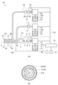
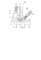
- FIG. 1A is a block diagram illustrating a configuration of the liquid ejecting apparatus.
- FIG. 1B is a partial schematic side view showing the structure of the nozzle of the liquid ejecting apparatus.
- the liquid ejecting apparatus 1 according to this embodiment is a medical device used in a medical institution, and has a function as a scalpel that performs incision or excision of an affected part by ejecting a fluid to the affected part.
- the liquid ejecting apparatus 1 includes a handpiece 2.
- the handpiece 2 is an instrument that is operated by a surgeon in his / her hand when performing an operation.
- the handpiece 2 is provided with an ejection pipe 3 that is a fluid flow path.
- a nozzle 4 is installed at one end of the ejection pipe 3 as a liquid ejection opening for ejecting fluid.
- a pulsation imparting portion 5 is installed at the other end of the ejection pipe 3.
- a first filter 7, a first flow meter 8, a first electromagnetic valve 9, and a first pump 10 are connected to the pulsation imparting unit 5 through a first tube 6 in this order.
- the pulsation imparting unit 5 is a part that makes the fluid passing through it a pulse flow.
- the first filter 7 has a function of removing foreign matters, bacteria, bubbles and the like in the fluid.
- the first flow meter 8 measures the flow rate of the fluid flowing through the first tube 6.
- the first flow meter 8 can be a hot wire flow meter, an impeller flow meter, or the like.
- the first electromagnetic valve 9 is a valve whose opening and closing is controlled by an electric signal.
- the first electromagnetic valve 9 may be a valve that opens and closes with a motor or an electromagnet.
- the first pump 10 can be a syringe pump or a tube pump. In the case of a syringe type, it is preferable to install a device for supplying fluid into the syringe. Thereby, the liquid ejecting apparatus 1 can be continuously driven.
- the first pump 10 is provided with a water inlet pipe 10 a, and one end of the water inlet pipe 10 a is connected to the first water tank 11.
- the first water tank 11 contains a first liquid 12 as a first liquid.
- physiological saline is used for the first liquid 12. Since physiological saline is not harmful to the living body, it can be used for surgery.
- the liquid ejecting apparatus 1 includes a control device 13 as control means, and the control device 13 controls the operation of the liquid ejecting apparatus 1.
- the pulsation imparting unit 5, the first flow meter 8, the first electromagnetic valve 9, and the first pump 10 are connected to the control device 13 by a cable 13a.
- a suction pipe 14 is installed in parallel with the injection pipe 3. At the tip of the suction tube 14, a liquid suction opening and a suction port 15 as a suction means are installed. A suction tube 14 is opened at the suction port 15. The nozzle 4 and the suction port 15 are located on substantially the same surface, and the suction port 15 is disposed in the vicinity of the nozzle 4. A suction tube 16 is connected to the suction tube 14. A suction flow meter 17 and a suction pump 18 are connected to the suction pipe 14 via a suction tube 16 in this order.
- a flow meter similar to the first flow meter 8 can be used.
- the suction pump 18 is not specifically limited, For example, a tube pump can be used.
- the suction pump 18 is provided with a drain pipe 18 a, and the drain pipe 18 a is connected to the drain tank 21.
- the drainage tank 21 stores the drained liquid 22 discharged from the drain pipe 18a.
- the suction flow meter 17 and the suction pump 18 are connected to the control device 13 by a cable 13a.
- a suction means is constituted by the suction port 15, the suction pipe 14, the suction pump 18, and the like.
- a supply pipe 23 is installed in parallel with the injection pipe 3 and the suction pipe 14.
- a supply port 24 is provided on the side facing the nozzle 4, and the supply pipe 23 is open at the supply port 24.
- the supply port 24 is disposed in the vicinity of the nozzle 4.
- a second tube 25 is installed on the supply pipe 23 on the side facing the pulsation imparting unit 5.
- a second filter 26, a second flow meter 27, a second electromagnetic valve 28, and a second pump 29 are connected to the supply pipe 23 through a second tube 25 in this order.
- the second filter 26 has the same function as the first filter 7 and can use the same thing.
- the second flow meter 27 has the same function as the first flow meter 8 and can use the same thing.
- the second electromagnetic valve 28 has the same function as the first electromagnetic valve 9 and can use the same thing.
- the second pump 29 is not particularly limited, and for example, a tube pump can be used.
- a water inlet pipe 29 a is installed in the second pump 29, and one end of the water inlet pipe 29 a is connected to the second water storage tank 30.
- the second water tank 30 contains a second liquid 31 as a second liquid.
- pure water is used for the second liquid 31. Since pure water is not harmful to the living body, it can be used for surgery.
- the second flow meter 27, the second electromagnetic valve 28, and the second pump 29 are connected to the control device 13 by a cable 13a.
- the supply port 24, the supply pipe 23, the second pump 29, etc. constitute a second liquid supply means.
- a proximity sensor 32 as a distance detecting means is installed on the side surface of the suction tube 14, and the proximity sensor 32 is connected to the control device 13 by a cable 13a.
- the handpiece 2 is used by bringing the nozzle 4 close to a living body.
- the proximity sensor 32 measures a distance from a living body located near the nozzle 4. Thereby, the proximity sensor 32 detects the distance between the living body and the nozzle 4 in the direction in which the first liquid 12 is ejected from the nozzle 4.
- various types of sensors such as a capacitance type, an optical type, and an ultrasonic type can be used.
- the control device 13 is provided with a main switch 33 and an injection switch 34 as a switch.
- the main switch 33 is a switch that activates the liquid ejecting apparatus 1.
- the ejection switch 34 is a switch for switching between ejection and non-ejection of fluid from the nozzle 4.
- the injection switch 34 is a switch that is operated by the operator by stepping on the foot.
- the control device 13 When the operator turns on the main switch 33, the control device 13 is initialized. Then, the surgeon turns on the injection switch 34. The first pump 10 is activated, and the first pump 10 causes the first liquid 12 to flow through the first electromagnetic valve 9. And when the control apparatus 13 opens the 1st solenoid valve 9, the 1st liquid 12 with a high pressure turns into a fluid, and advances the 1st tube 6. FIG. Then, the first flow meter 8 detects the flow rate of the fluid traveling through the first tube 6 and outputs it to the control device 13.
- the fluid traveling through the first tube 6 passes through the first filter 7.
- dust, bubbles, salt crystals, and the like are removed from the first liquid 12.
- the first liquid 12 that has reached the pulsation imparting unit 5 is pulsated by the pulsation imparting unit 5.
- the first liquid 12 that has passed through the pulsation imparting unit 5 passes through the ejection pipe 3 and is ejected from the nozzle 4. Since the pulsation is applied to the first liquid 12 that has passed through the nozzle 4, a pulse-like jet is formed.
- the suction pump 18 When the surgeon turns on the injection switch 34, the suction pump 18 is activated in parallel with the activation of the first pump 10.
- the suction pump 18 sucks the liquid located at the suction port 15.
- the sucked liquid enters the suction tube 14 from the suction port 15 and reaches the suction pump 18 through the suction tube 16. Then, the sucked liquid is discharged as drainage 22 into the drainage tank 21.
- the suction flow meter 17 detects the flow rate of the fluid traveling through the suction tube 16 and outputs it to the control device 13.
- the second pump 29 When the surgeon turns on the injection switch 34, the second pump 29 is activated in parallel with the activation of the first pump 10. When the second pump 29 is activated, the second pump 29 causes the second liquid 31 to flow to the second electromagnetic valve 28. And when the control apparatus 13 opens the 2nd solenoid valve 28, the 2nd liquid 31 becomes a fluid and advances the 2nd tube 25. FIG. Then, the second flow meter 27 detects the flow rate of the fluid traveling through the second tube 25 and outputs it to the control device 13.
- the fluid traveling through the second tube 25 passes through the second filter 26.
- the second filter 26 removes dust and the like from the second liquid 31.
- the second liquid 31 that has reached the supply port 24 from the second filter 26 through the second tube 25 and the supply tube 23 is supplied to the vicinity of the nozzle 4.
- the suction ports 15 are arranged concentrically around the nozzle 4.
- the injection tube 3 is inserted in the suction tube 14. Thereby, the liquid accumulated in the nozzle 4 can be sucked evenly. Therefore, since the second liquid 31 is evenly arranged around the nozzle 4, scattering of the ejected first liquid 12 can be suppressed.
- a cylindrical supply pipe 23 is disposed on the outer periphery of the suction pipe 14.
- a proximity sensor 32 is disposed on the outer periphery of the suction pipe 14 on the opposite side of the supply port 24 with the nozzle 4 as the center. Since the proximity sensor 32 is away from the supply port 24, the influence of the second liquid 31 supplied from the supply port 24 can be reduced.
- FIG. 2A and 2 (b) are schematic diagrams for explaining the behavior of the liquid in the nozzle.
- the operator operates the handpiece 2 to bring the nozzle 4 close to the living body 35 as an object.
- the second liquid 31 is supplied from the supply port 24.
- the second liquid 31 proceeds between the nozzle 4 and the living body 35. Since the surface tension acts on the second liquid 31, the second liquid 31 stays between the nozzle 4 and the living body 35 and forms a liquid pool 36.
- the second liquid 31 is pure water, and the first liquid 12 is physiological saline. Accordingly, the second liquid 31 has a surface tension greater than that of the first liquid 12. For this reason, the cohesive force of the second liquid 31 is improved in the nozzle 4, and the nozzle 4 is immersed in the second liquid 31 (water column), or the liquid wall (water wall) of the second liquid 31 is the nozzle 4. It becomes easy to do around.
- the figure shows the water column. When a cavity is formed in the liquid pool 36 at a location facing the ejection pipe 3, the liquid pool 36 becomes cylindrical. This state is called a water wall.
- the control device 13 controls the flow rate of the liquid sucked from the suction port 15 to be smaller than the flow rate of the second liquid 31 supplied from the supply port 24. As a result, a liquid pool 36 is stably formed between the nozzle 4 and the living body 35.
- the first liquid 12 ejected from the nozzle 4 collides with the collision point 35a of the living body 35. Then, some cell groups 37 of the living body 35 are separated from the living body 35. The first liquid 12 and the cell group 37 that have collided with the living body 35 are decelerated when moving in the liquid pool 36. For this reason, the 1st liquid 12 and the cell group 37 which collided with the biological body 35 remain in the liquid pool 36, and are prevented from scattering far from the collision point 35a.
- the supply flow rate of the second liquid 31 supplied from the supply port 24 is 5 ml / min or more.
- the supply flow rate of the second liquid 31 is 5 ml / min or more with the suction amount for sucking the excised or crushed cell group 37 secured, the tip of the nozzle 4 is immersed in the second liquid 31 (water column) Or a liquid wall (water wall) by the second liquid 31 can be easily formed around the nozzle 4. Therefore, scattering of the ejected first liquid 12 and the cell group 37 can be suppressed.
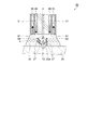
- FIG. 3A is a schematic cross-sectional view showing the internal configuration of the pulsation imparting section.
- the pulsation imparting unit 5 is provided with an inlet channel 38, a liquid chamber 41, and an outlet channel 42 through which the first liquid 12 supplied from the first tube 6 passes.
- the inlet channel 38 and the outlet channel 42 are formed in the first case 43.
- the diaphragm 44 is installed so that the liquid chamber 41 is sandwiched between the first case 43 and the diaphragm 44.
- the first tube 6 is connected to the inlet flow path 38, and the injection pipe 3 is connected to the outlet flow path 42.
- a cylindrical second case 45 is installed on the right side of the first case 43 in the drawing in contact with the first case 43.
- the diaphragm 44 is a disk-shaped metal thin plate, and the outer peripheral portion of the diaphragm 44 is sandwiched and fixed between the first case 43 and the second case 45.
- a third case 46 is installed on the right side of the second case 45 in the drawing in contact with the second case 45.
- a piezoelectric element 47 is disposed as a volume changing means, which is a laminated piezoelectric element. One end of the piezoelectric element 47 is fixed to the diaphragm 44, and the other end is fixed to the third case 46.
- the piezoelectric element 47 is connected to the control device 13 by a cable 13a.
- the piezoelectric element 47 changes the volume of the liquid chamber 41 formed between the diaphragm 44 and the first case 43.
- the drive voltage applied to the piezoelectric element 47 increases, the piezoelectric element 47 expands and the diaphragm 44 is pushed by the piezoelectric element 47 and bends toward the liquid chamber 41 in the first direction 48 in the drawing.
- the diaphragm 44 bends in the first direction 48, the volume of the liquid chamber 41 decreases. Then, the fluid in the liquid chamber 41 is pushed out of the liquid chamber 41.
- the inner diameter of the outlet channel 42 is larger than the inner diameter of the inlet channel 38.
- the fluid resistance of the outlet channel 42 is smaller than the fluid resistance of the inlet channel 38. Since the inlet channel 38 is closer to the first pump 10 than the outlet channel 42, the water pressure in the inlet channel 38 is higher than the water pressure in the outlet channel 42. Therefore, most of the fluid in the liquid chamber 41 is pushed out of the liquid chamber 41 through the outlet channel 42.
- the piezoelectric element 47 contracts, and the diaphragm 44 is pulled by the piezoelectric element 47 and bends toward the third case 46 in the second direction 49 in the drawing.
- the piezoelectric element 47 is contracted to increase the volume of the liquid chamber 41, and fluid is supplied from the inlet channel 38 into the liquid chamber 41.
- the drive voltage applied to the piezoelectric element 47 is repeatedly turned on (maximum voltage) and turned off (0 V) at a high frequency (for example, 300 Hz), the volume of the liquid chamber 41 is repeatedly expanded and reduced, and the fluid pulsates. Given. The fluid pushed out from the liquid chamber 41 is ejected from the nozzle 4 at the tip of the ejection tube 3.
- FIG. 3B is a graph showing the transition of the volume of the liquid chamber.
- the vertical axis indicates the volume of the liquid chamber 41, and the upper side in the figure is smaller than the lower side.
- the horizontal axis shows the transition of time, and the time transitions from the left side to the right side in the figure.
- the first transition line 50 shows the transition of the volume when the volume of the liquid chamber 41 is greatly changed.
- the second transition line 51 shows the transition of the volume when the volume of the liquid chamber 41 is changed small.
- the first transition line 50 and the second transition line 51 are repeated with the same period 52.
- the first transition line 50 and the second transition line 51 have similar shapes, and the transition of the volume change will be described using the first transition line 50.
- One cycle 52 is divided into a rising section 53, a falling section 54, and a rest section 55.
- the first transition line 50 has a shape similar to a sine waveform.
- a voltage is applied to the piezoelectric element 47 and the piezoelectric element 47 expands. Thereby, the diaphragm 44 moves in the first direction 48 and the volume of the liquid chamber 41 decreases. Then, the first liquid 12 in the liquid chamber 41 moves to the outlet channel 42.
- the first transition line 50 has a shape similar to a sine waveform.
- the voltage applied to the piezoelectric element 47 decreases and the piezoelectric element 47 contracts.
- the diaphragm 44 moves in the second direction 49 and the volume of the liquid chamber 41 increases.
- the first liquid 12 flows into the liquid chamber 41 from the inlet channel 38.
- the falling section 54 is longer than the rising section 53.
- the first liquid 12 vigorously flows into the outlet channel 42 and flows in from the inlet channel 38 at a low speed.
- the rest section 55 is a section in which the piezoelectric element 47 maintains a contracted state.
- the period 52 can be adjusted by changing the length of the pause section 55.
- the amount of change in volume on the first transition line 50 is the first amount of change 50a
- the amount of change in volume on the second transition line 51 is the second amount of change 51a.
- the change amount such as the first change amount 50 a and the second change amount 51 a can be adjusted by the control device 13 controlling the piezoelectric element 47.
- FIG. 3C is a graph showing the relationship between the second liquid supply amount and the volume change amount of the liquid chamber.
- the vertical axis indicates the supply amount of the second liquid 31 supplied from the supply port 24.
- the upper side in the figure is larger than the lower side.
- the horizontal axis indicates the amount of change in the volume of the liquid chamber 41, and the amount of change on the right side in the figure is greater than that on the left side.
- the volume supply amount correlation line 56 shows the relationship between the volume change amount of the liquid chamber 41 and the supply amount of the second liquid 31. Although the volume supply amount correlation line 56 in the figure is a straight line, it may be a curved line or a broken line.
- the supply amount of the second liquid 31 when the change amount of the volume of the liquid chamber 41 is the first change amount 50 a is a first supply amount 57.
- the supply amount of the second liquid 31 when the change amount of the volume of the liquid chamber 41 is the second change amount 51 a is set as a second supply amount 58.
- the first change amount 50a is larger than the second change amount 51a, the volume fluctuation of the pulse flow in the first liquid 12 discharged from the nozzle 4 becomes large. And the energy of the 1st liquid 12 which moves after colliding with the biological body 35 becomes so large that the fluctuation
- the first supply amount 57 corresponding to the first change amount 50a is larger than the second supply amount 58 corresponding to the second change amount 51a. Therefore, even if the energy applied to the pulse flow of the first liquid 12 is large, the amount of the second liquid 31 becomes large, so that the volume of the liquid pool 36 becomes large. Therefore, the first liquid 12 can be prevented from scattering from the liquid pool 36.
- the control device 13 when the control device 13 reduces the change amount of the volume of the liquid chamber 41 from the first change amount 50a to the second change amount 51a, the second liquid 31 supplied from the supply port 24 by the control device 13 is supplied to the first supply amount.
- the amount 57 is reduced to the second supply amount 58.
- the control device 13 suppresses scattering by reducing the supply amount of the second liquid 31 supplied from the supply port 24. Therefore, the consumption of the second liquid 31 can be reduced.
- FIG. 4 is an electric control block diagram of the liquid ejecting apparatus 1.
- the liquid ejecting apparatus 1 includes a control device 13 that controls the operation of the liquid ejecting apparatus 1. And the control apparatus 13 is provided with CPU61 (central processing unit) which performs various arithmetic processes as a processor, and the memory 62 which memorize
- the pump driving device 63, the first flow meter 8, the second flow meter 27, the suction flow meter 17, the pulsation imparting unit 5, and the proximity sensor 32 are connected to the CPU 61 via the input / output interface 64 and the data bus 65.
- main switch 33 the injection switch 34, the pulsation amount input device 66, the suction setting input device 67, the output device 68 and the input device 69 are also connected to the CPU 61 via the input / output interface 64 and the data bus 65.
- the pump drive device 63 is a device that drives the first pump 10, the second pump 29, the suction pump 18, the first electromagnetic valve 9, and the second electromagnetic valve 28.
- the pump driving device 63 receives an instruction signal from the CPU 61. Then, the pump driving device 63 drives the first pump 10, the second pump 29, and the suction pump 18 with the pressure or flow rate indicated in the instruction signal. Further, the pump driving device 63 drives the first electromagnetic valve 9 and the second electromagnetic valve 28 to open and close the valves.
- the pulsation amount input device 66 is a device by which an operator inputs the fluctuation amount of the pulsation of the first liquid 12.
- the pulsation amount input device 66 is, for example, a device for setting the volume change amount of the liquid chamber 41 to, for example, the first change amount 50a or the second change amount 51a.
- the pulsation amount input device 66 can be configured by, for example, a variable resistor, a circuit that converts the resistance value of the variable resistor into a voltage, a plurality of switches, and the like.
- the suction setting input device 67 is a device for setting the suction amount of the liquid sucked from the suction port 15 by the operator.
- the output device 68 includes a light and speaker for notifying abnormality, a device for performing wired and wireless communication with an external computer, and the like. Thereby, the control device 13 can output the state of the liquid ejecting apparatus 1 and the setting state set by the operator.
- the input device 69 includes a keyboard, a mouse-type input device, a pen-type input device, and a device that performs wired and wireless communication with an external computer. Various data are input to the memory 62 by these input devices 69.
- the memory 62 is a concept including a semiconductor memory such as a RAM and a ROM, and an external storage device such as a hard disk and a DVD-ROM. Functionally, a storage area for storing program software 70 in which a control procedure of the operation of the liquid ejecting apparatus 1 is described, and supply amount calculation data 71 that is data used when calculating the supply amount of the second liquid 31 are stored. A storage area for storing is set. In addition, a storage area for storing determination value data 72, which is data used for determination when performing various controls, is set. In addition, a work area for the CPU 61, a storage area that functions as a temporary file, and other various storage areas are set.
- the CPU 61 performs control to eject the first liquid 12 from the nozzle 4 of the handpiece 2 in accordance with the program software 70 stored in the memory 62.
- a pump control unit 73 is provided as a specific function realization unit.
- the pump control unit 73 outputs an instruction signal to the pump driving device 63 to drive the first pump 10, the second pump 29, and the suction pump 18 to cause the first liquid 12 and the second liquid 31 to flow and be sucked. Do. Further, the pump control unit 73 controls the flow and stop of the flow of the first liquid 12 and the second liquid 31 by opening and closing the first electromagnetic valve 9 and the second electromagnetic valve 28.
- the CPU 61 has a pulsation control unit 74.
- the pulsation control unit 74 inputs the pulsation amount set by the pulsation amount input device 66.
- the pulsation control unit 74 controls the amount of fluctuation of the liquid chamber 41 by controlling the piezoelectric element 47 of the pulsation imparting unit 5.
- the CPU 61 has a suction amount calculation unit 75 as an adjusting means.
- the suction amount calculation unit 75 calculates an appropriate suction amount according to the supply amount of the second liquid 31.
- the suction amount calculation unit 75 calculates a total liquid flow rate that is the sum of the flow rate of the first liquid 12 ejected from the nozzle 4 and the flow rate of the second liquid 31 supplied from the supply port 24. Then, the suction amount calculation unit 75 calculates a suction amount that is a flow rate of the sucked liquid so that the flow rate of the liquid sucked from the suction port 15 becomes smaller than the total liquid flow rate. Then, the calculated suction amount is output to the pump control unit 73.
- the tip of the nozzle 4 is the second liquid.
- a state of being immersed in 31 (water column) or a liquid wall (water wall) by the second liquid 31 is easily formed around the nozzle 4. Since the suction amount is adjusted, scattering of the first liquid 12 to be ejected can be reduced.
- the CPU 61 has a supply amount calculation unit 76 as an adjusting means.
- the supply amount calculation unit 76 calculates the supply amount of the second liquid 31 supplied from the supply port 24 using the volume supply amount correlation line 56 based on the change amount of the volume of the liquid chamber 41. Then, the supply amount is output to the pump control unit 73. The supply amount is controlled by the supply amount calculation unit 76 and the pump control unit 73.
- the speed of the pulse flow of the first liquid 12 is fast and the amount of the first liquid 12 to be ejected increases, so that the splatter also increases.
- the second liquid 31 supplied from the supply port 24 is increased. Therefore, it is possible to suppress the cell group 37 excised or crushed by the ejected first liquid 12 and the liquid containing the ejected first liquid 12 from being scattered.
- the speed of the pulse flow of the first liquid 12 is slow, and the amount of the first liquid 12 to be ejected is also reduced, so that scattering is also reduced. For this reason, even if the amount of the second liquid 31 supplied from the supply port 24 is reduced, scattering can be suppressed. As a result, the consumption of the second liquid 31 can be reduced.
- the CPU 61 has a liquid supply determination unit 77.
- the liquid supply determination unit 77 drives the proximity sensor 32 to detect a nozzle inter-vivo distance that is a distance between the nozzle 4 and the living body 35. Then, the liquid supply determination unit 77 compares the nozzle living body distance with the determination value.
- the liquid supply determination unit 77 controls to supply the second liquid 31 from the supply port 24 when the nozzle inter-vivo distance is shorter than the determination value.
- the liquid supply determination unit 77 controls to stop supplying the second liquid 31 from the supply port 24 when the nozzle inter-vivo distance is longer than the determination value.
- the tip of the nozzle 4 When the nozzle 4 is close to the living body 35, the tip of the nozzle 4 is likely to be immersed in the second liquid 31 (water column) or a state where the wall of the second liquid 31 is formed (water wall).
- the second liquid 31 supplied from the supply port 24 can suppress the cell group 37 excised or crushed by the ejected first liquid 12 and the scattering of the liquid containing the ejected first liquid 12. Since the liquid supply determination unit 77 supplies the second liquid 31 only when the second liquid 31 has an effect, the consumption of the second liquid 31 can be reduced.
- each function described above is realized by program software using the CPU 61.
- each function described above can be realized by a single electronic circuit (hardware) that does not use the CPU 61, It is also possible to use such an electronic circuit.
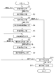
- FIG. 5 is a flowchart of a cutting method for cutting the surface of a living body
- FIG. 6 is a flowchart of a supply amount adjusting process.
- step S1 corresponds to a start determination step.
- This step is a step for determining whether the surgeon has turned on the main switch 33. The operation waits until the surgeon turns on the main switch 33. When the surgeon turns on the main switch 33, the process proceeds to step S2.
- Step S2 corresponds to a suction start process.
- the pump control unit 73 causes the pump driving device 63 to drive the suction pump 18. At this time, since the second liquid 31 is not supplied, the suction pump 18 sucks air. Next, the process proceeds to step S3.
- Step S3 corresponds to an injection determination process.
- the CPU 61 detects whether the injection switch 34 is ON or OFF. Then, when the ejection switch 34 is ON, the CPU 61 determines to eject the first liquid 12, and then proceeds to step S4. When the ejection switch 34 is OFF, the CPU 61 determines that the first liquid 12 is not ejected, and then proceeds to step S10.
- Step S4 corresponds to a first liquid supply start process.
- the pump control unit 73 causes the pump driving device 63 to drive the first pump 10.
- the first pump 10 causes the first liquid 12 to flow toward the pulsation imparting unit 5.
- the process proceeds to step S5.
- Step S5 corresponds to a pulsation start process.
- the pulsation control unit 74 inputs the pulsation set amount set in the pulsation amount input device 66.
- the surgeon sets the pulsation amount in advance.
- the surgeon can also change the amount of pulsation during the work.
- the pulsation control unit 74 drives the pulsation imparting unit 5 so that the first liquid 12 is ejected with the set pulsation amount.
- step S6 proceeds to step S6.
- Step S6 corresponds to a supply amount adjustment process.
- the supply amount calculation unit 76 calculates the supply amount of the second liquid 31 supplied from the supply port 24.
- the pump control unit 73 causes the pump driving device 63 to drive the second pump 29.
- the pump control unit 73 supplies the calculated supply amount of the second liquid 31 from the supply port 24.
- Steps S4 to S6 are performed substantially simultaneously. Accordingly, when the first liquid 12 is ejected, the second pump 29 supplies the second liquid 31 from the supply port 24.
- the surgeon brings the nozzle 4 close to the living body 35. Thereby, the first liquid 12 is jetted onto the living body 35 and the cell group 37 of the living body 35 is partially removed from the living body 35.
- the living body 35 is cut when the operator removes the cell group 37 at a predetermined location from the living body 35.
- the process proceeds to step S7.
- Step S7 corresponds to an injection stop determination step.
- the CPU 61 detects whether the injection switch 34 is ON or OFF. When the ejection switch 34 is ON, the CPU 61 determines to continue the ejection of the first liquid 12, and then proceeds to step S6. When the ejection switch 34 is OFF, the CPU 61 determines to stop the ejection of the first liquid 12, and then proceeds to step S8.
- Step S8 corresponds to a pulsation stop process.
- the pulsation control unit 74 stops driving the pulsation imparting unit 5.
- the process proceeds to step S9.
- Step S9 corresponds to a liquid supply stop process.
- the pump control unit 73 causes the pump driving device 63 to stop driving the first pump 10 and the second pump 29. Thereby, the ejection of the first liquid 12 from the nozzle 4 is stopped, and the supply of the second liquid 31 from the supply port 24 is also stopped.
- the process proceeds to step S3.
- Steps S7 to S9 are performed substantially simultaneously.
- the pump control unit 73 controls the first pump 10 and the second pump 29 so that the second liquid 31 is not supplied from the supply port 24. Therefore, the second liquid 31 is not wasted when the first liquid 12 is not ejected. Therefore, the consumption of the second liquid 31 can be reduced.
- Step S10 corresponds to an end determination step.
- This step is a step of determining whether the surgeon has turned off the main switch 33. When the surgeon keeps the main switch 33 turned on, it is determined that the operation is continued and not finished. Next, the process proceeds to step S3. When the surgeon turns off the main switch 33, it is determined that the work is finished. Next, the process proceeds to step S11.
- Step S11 corresponds to a suction end process.
- This step is a step in which the pump control unit 73 causes the pump driving device 63 to stop driving the suction pump 18. With the above process, the process of cutting the surface of the living body is completed.
- step S12 corresponds to a distance measuring step.
- the liquid supply determination unit 77 drives the proximity sensor 32. Then, the liquid supply determination unit 77 detects the inter-nozzle living body distance that is the distance between the nozzle 4 and the living body 35. Next, the process proceeds to step S13.
- Step S13 corresponds to a second liquid determination step.
- the liquid supply determination unit 77 compares the nozzle living body distance with the determination value. When the nozzle living body distance is shorter than the determination value, the liquid supply determination unit 77 determines to supply the second liquid 31 from the supply port 24.
- the process proceeds to step S14. When the nozzle inter-vivo distance is longer than the determination value, it is determined that the second liquid 31 is not supplied from the supply port 24. Then, the control device 13 may drive the output device 68 to alert the operator to bring the nozzle 4 closer to the living body 35. For example, a warning sound may be emitted from a speaker, or a character or figure indicating a warning may be displayed.
- the process proceeds to step S15.
- Step S14 corresponds to a second liquid supply start process.
- the pump control unit 73 causes the pump driving device 63 to drive the second pump 29.
- the second pump 29 causes the second liquid 31 to flow toward the supply port 24.
- the process proceeds to step S15.
- Step S15 corresponds to a supply amount measurement process.
- the suction amount calculation unit 75 drives the first flow meter 8 and the second flow meter 27.
- the first flow meter 8 detects the flow rate of the first liquid 12 and outputs it to the suction amount calculation unit 75.
- the second flow meter 27 detects the flow rate of the second liquid 31 and outputs it to the suction amount calculation unit 75.
- the process proceeds to step S16.
- Step S16 corresponds to a suction amount adjustment process.
- the suction amount calculation unit 75 calculates the total liquid flow rate. Then, the suction amount calculation unit 75 calculates a suction amount instruction value that is a flow rate of the sucked liquid so that the flow rate of the liquid sucked from the suction port 15 becomes smaller than the total liquid flow rate. Then, the calculated suction amount instruction value is output to the pump control unit 73. The suction pump 18 adjusts the suction amount so that the suction amount from the suction port 15 becomes the suction amount instruction value.
- step S12 the operator cuts the living body 35. Accordingly, the surgeon ejects the first liquid 12 from the handpiece 2 and performs a surgical treatment on the living body 35.
- description of the supply amount adjustment process of step S6 is complete
- the second liquid 31 is supplied from the supply port 24 to the nozzle 4 so that the tip of the nozzle 4 is immersed in the second liquid 31 (water column) or the second liquid.
- a liquid wall (water wall) 31 is formed around the nozzle 4.
- excess second liquid 31 can be sucked by the suction port 15 disposed in the vicinity of the nozzle 4. Therefore, it is possible to prevent the surgical field from being flooded.
- the liquid accumulated in the nozzle 4 can be sucked evenly.
- a state in which the tip of the nozzle 4 is immersed in the second liquid 31 without any bias (water column) or a state in which a liquid wall is formed by the second liquid 31 (water wall) is formed around the nozzle 4. Since the suction pipe 14 sucks the excessive second liquid 31 positioned around the nozzle 4 relatively evenly, it is possible to suppress scattering of the ejected first liquid 12.
- the flow rate of the pulse flow of the first liquid 12 is high, and the scattering of the first liquid 12 is also large.
- the second liquid 31 supplied from the supply port 24 is increased. Therefore, it is possible to suppress the cell group 37 excised or crushed by the ejected first liquid 12 and the liquid containing the ejected first liquid 12 from being scattered.
- the change amount of the volume of the liquid chamber 41 is small, the speed of the pulse flow of the first liquid 12 is slow and the amount of the first liquid 12 to be ejected is also reduced, so that the splatter is also reduced. For this reason, even if the amount of the second liquid 31 supplied from the supply port 24 is reduced, scattering can be suppressed. As a result, the consumption of the second liquid 31 can be reduced.
- the liquid ejecting apparatus 1 includes the supply amount calculation unit 76 and the pump control unit 73 that control the supply amount of the second liquid 31.
- the supply amount calculation unit 76 increases the supply amount of the second liquid 31 supplied from the supply port 24, the scattering of the first liquid 12 can be suppressed.
- the supply amount calculation unit 76 reduces the supply amount of the second liquid 31 supplied from the supply port 24 and suppresses scattering. Therefore, the consumption of the second liquid 31 can be reduced.
- the second liquid 31 when the injection of the first liquid 12 is stopped, the second liquid 31 is not supplied from the supply port 24. Therefore, the second liquid 31 is not wasted when the first liquid 12 is not ejected. Therefore, the consumption of the second liquid 31 can be reduced.
- the proximity sensor 32 detects the distance between the nozzle 4 and the living body 35.
- the liquid supply determination unit 77 supplies the second liquid 31 from the supply port 24.
- the nozzle 4 is close to the living body 35, the tip of the nozzle 4 is easily immersed in the first liquid 12, or the wall of the first liquid 12 is easily formed around the nozzle 4. It is possible to suppress scattering of a liquid including the cell group 37 excised or crushed by the first liquid 12 ejected by the second liquid 31 supplied from the supply port 24 and the ejected first liquid 12. Since the liquid supply determining unit 77 supplies the second liquid 31 when there is an effect of supplying the second liquid 31, the consumption of the second liquid 31 can be reduced.
- the tip of the nozzle 4 is immersed in the second liquid 31 (water column) or the liquid wall (water) by the second liquid 31. Wall) is difficult to form around the nozzle 4.
- the second liquid 31 supplied from the supply port 24 is wasted. Since the supply of the second liquid 31 is stopped when the nozzle 4 is far from the living body 35, the second liquid 31 is not wasted. Therefore, since the liquid supply determination unit 77 supplies the second liquid 31 when the second liquid 31 is effective, the consumption of the second liquid 31 can be reduced.
- the second liquid 31 is pure water and the first liquid 12 is physiological saline.
- the second liquid 31 has a surface tension greater than that of the first liquid 12. For this reason, the cohesive force of the second liquid 31 is improved in the nozzle 4, and the nozzle 4 is immersed in the second liquid 31 (water column), or the liquid wall (water wall) of the second liquid 31 is the nozzle 4. It becomes easy to do around. As a result, scattering of the ejected first liquid 12 can be easily suppressed.
- the suction amount calculation unit 75 adjusts the flow rate of the liquid to be sucked. If the sum of the flow rate of the first liquid 12 ejected from the nozzle 4 and the flow rate of the second liquid 31 supplied from the supply port 24 is larger than the flow rate of the liquid sucked from the suction port 15, the tip of the nozzle 4 is the second liquid. A state of being immersed in 31 (water column) or a liquid wall (water wall) by the second liquid 31 is easily formed around the nozzle 4. Since the suction amount is adjusted by the suction amount calculation unit 75, a water column or a water wall can be easily formed. As a result, scattering of the ejected first liquid 12 can be reduced.
- the supply flow rate of the second liquid 31 supplied from the supply port 24 is 5 ml / min or more.
- the supply flow rate of the second liquid 31 is 5 ml / min or more with the suction amount for sucking the excised or crushed cell group 37 secured, the tip of the nozzle 4 is immersed in the second liquid 31 (water column) Or a liquid wall (water wall) by the second liquid 31 can be easily formed around the nozzle 4. Therefore, scattering of the ejected first liquid 12 and the cell group 37 can be suppressed.
- the liquid ejecting apparatus 1 is used for the surgical instrument. Therefore, it is possible to prevent the cell group 37 excised or crushed by the ejected first liquid 12 and the liquid containing the ejected first liquid 12 from being scattered. As a result, a surgical procedure (incision, excision, crushing, etc.) is performed while preventing the surgical field from being contaminated by the scattering of the cell group 37 that has been excised or crushed or the liquid containing the ejected first liquid 12. Can do.
- FIG. 7A is a block diagram illustrating a configuration of the liquid ejecting apparatus.
- FIG. 7B is a partial schematic side view illustrating the structure of the nozzle of the liquid ejecting apparatus.
- FIG. 8 is a schematic diagram for explaining the behavior of the liquid in the nozzle.
- This embodiment is different from the first embodiment in that the arrangement of the suction tube 14 and the supply tube 23 shown in FIG. 1 is different. Note that description of the same points as in the first embodiment is omitted.
- the liquid ejecting apparatus 80 includes a hand piece 81 as shown in FIG.
- a suction pipe 14 is installed around the injection pipe 3, and a supply pipe 82 is installed around the suction pipe 14.
- a supply port 83 is provided at the tip of the supply pipe 82.
- the nozzle 4, the suction port 15, and the supply port 83 are arranged on the same surface.
- the suction pipe 14 and the supply pipe 82 are arranged concentrically around the injection pipe 3. That is, the injection pipe 3 is inserted into the supply pipe 82.
- the second liquid 31 supplied from the supply port 83 is sucked into the suction tube 14 from the suction port 15.
- a liquid pool 36 is formed between the nozzle 4, the suction port 15, the supply port 83 and the living body 35. Then, the first liquid 12 is ejected from the nozzle 4 toward the collision point 35 a in the liquid pool 36.
- this embodiment has the following effects.
- (1) since the supply pipe 82 is inserted in the injection pipe 3, the liquid can be supplied uniformly from around the nozzle 4. For this reason, the liquid ejecting apparatus 80 easily forms a liquid wall (water wall) by the second liquid 31 around the nozzle 4. Therefore, the cell group 37 excised or crushed by the ejected first liquid 12 and the liquid containing the ejected first liquid 12 are prevented from scattering beyond the second liquid around the tip of the nozzle 4. be able to. Further, the direction in which the supply pipe 82 supplies the second liquid 31 can be made to follow the direction in which the nozzle 4 ejects the first liquid 12.
- FIG. 9A is a block diagram illustrating a configuration of the liquid ejecting apparatus.
- FIG. 9B is a partial schematic side view illustrating the structure of the nozzle of the liquid ejecting apparatus.
- FIG. 10 is a schematic diagram for explaining the behavior of the liquid in the nozzle.
- This embodiment is different from the first embodiment in that the arrangement of the suction tube 14 and the supply tube 23 shown in FIG. 1 is different. Note that description of the same points as in the first embodiment is omitted.
- the liquid ejecting apparatus 86 includes a handpiece 87 as shown in FIG.
- a supply pipe 88 is installed around the injection pipe 3, and a supply port 89 is installed at the tip of the supply pipe 88.
- a suction tube 90 is installed around the supply tube 88, and a suction port 91 is installed at the tip of the suction tube 90.
- the nozzle 4, the supply port 89, and the suction port 91 are disposed on the same surface.
- the supply pipe 88 and the suction pipe 90 are arranged concentrically around the injection pipe 3. That is, the injection pipe 3 is inserted into the supply pipe 88.
- the second liquid 31 supplied from the supply port 89 is sucked into the suction tube 90 from the suction port 91.
- a liquid pool 36 is formed between the nozzle 4, the supply port 89 and the suction port 91 and the living body 35. Then, the first liquid 12 is ejected from the nozzle 4 toward the collision point 35 a in the liquid pool 36.
- this embodiment has the following effects.
- (1) since the supply pipe 88 is inserted in the injection pipe 3, the liquid can be supplied uniformly from around the nozzle 4. For this reason, the liquid ejecting apparatus 86 easily forms a liquid wall (water wall) by the second liquid 31 around the nozzle 4. Therefore, it is possible to suppress the cell group 37 excised or crushed by the ejected first liquid 12 and the liquid containing the ejected first liquid 12 from being scattered beyond the second liquid around the nozzle 4. . Further, the direction in which the supply pipe 88 supplies the second liquid 31 can be made to follow the direction in which the nozzle 4 ejects the first liquid 12.
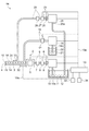
- FIG. 11 is a block diagram illustrating a configuration of the liquid ejecting apparatus. This embodiment is different from the first embodiment in that the first pump 10 and the second pump 29 shown in FIG. 1 cause the same liquid to flow. Note that description of the same points as in the first embodiment is omitted.
- the liquid ejecting apparatus 94 stores the first liquid 12 in the first water tank 11.
- the water inlet pipe 10 a of the first pump 10 and the water inlet pipe 29 a of the second pump 29 are connected to the first water storage tank 11. Accordingly, the first pump 10 and the second pump 29 flow the first liquid 12. Then, the first liquid 12 is ejected from the nozzle 4, and the first liquid 12 is also supplied from the supply port 24.
- this embodiment has the following effects. (1) According to this embodiment, it is not necessary to prepare the first liquid 12 and the second liquid 31 separately. Accordingly, since a container for the second liquid 31 is not necessary, the liquid ejecting device 94 can be made a small device.
- FIG. 12 is a block diagram illustrating a configuration of the liquid ejecting apparatus. This embodiment is different from the first embodiment in that the first pump 10 shown in FIG. 1 causes the same liquid to flow through the ejection pipe 3 and the supply pipe 23. Note that description of the same points as in the first embodiment is omitted.
- the third tube 98 is connected to the first tube 6 that connects the first filter 7 and the pulsation imparting unit 5.
- the third tube 98 connects the first tube 6 and the supply pipe 23.
- the first liquid 12 that is flowed by the first pump 10 is supplied to the pulsation imparting unit 5 and the supply pipe 23.
- the first pump 10 flows the first liquid 12. Then, the first liquid 12 is ejected from the nozzle 4, and the first liquid 12 is also supplied from the supply port 24.
- this embodiment has the following effects. (1) According to this embodiment, it is not necessary to prepare the first liquid 12 and the second liquid 31 separately. Accordingly, since a container for the second liquid 31 is not necessary, the liquid ejecting apparatus 97 can be made a small apparatus.
- the first pump 10 causes the first liquid 12 to flow through the pulsation imparting unit 5 and the supply pipe 23. Therefore, the number of pumps can be reduced as compared with the case where the supply pipe 23 includes a pump for flowing the first liquid 12 in addition to the first pump 10 for flowing the first liquid 12 in the pulsation imparting unit 5. Therefore, the liquid ejecting apparatus 97 can be made a small apparatus.
- FIG. 13A is a block diagram illustrating a configuration of the liquid ejecting apparatus.
- FIG. 13B is a partial schematic side view illustrating the structure of the nozzle of the liquid ejecting apparatus.
- FIG. 14 is a schematic diagram for explaining the behavior of the liquid in the nozzle.
- This embodiment differs from the first embodiment in that the suction tube 14 shown in FIG. 1 is separate from the handpiece 2. Note that description of the same points as in the first embodiment is omitted.
- the liquid ejecting apparatus 101 includes a first handpiece 102 and a second handpiece 103.
- a pulsation imparting unit 5 is installed on the first handpiece 102, and an ejection pipe 3 is installed in connection with the pulsation imparting unit 5.
- a supply pipe 23 and a proximity sensor 32 are installed in parallel with the injection pipe 3.
- the first liquid 12 that is flowed by the first pump 10 is supplied to the injection pipe 3. Then, a pulse flow of the first liquid 12 is ejected from the nozzle 4.
- the supply pipe 23 is supplied with the second liquid 31 that is flowed by the second pump 29. Then, the second liquid 31 is supplied from the supply port 24.
- the second handpiece 103 includes a suction tube 104, and a suction port 105 is provided at the tip of the suction tube 104.
- a suction tube 104 is opened at the suction port 105.
- a suction tube 16 is connected to the suction tube 104.
- a suction flow meter 17 and a suction pump 18 are connected to the suction pipe 104 via a suction tube 16.
- the first handpiece 102 is provided with the nozzle 4 and the supply port 24, and the second handpiece 103 is provided with the suction port 105. Therefore, the operator can operate the nozzle 4 and the suction port 105 separately.
- the surgeon operates the first handpiece 102 to bring the nozzle 4 closer to the living body 35.
- the second liquid 31 is supplied from the supply port 24.
- the second liquid 31 is supplied between the nozzle 4 and the living body 35. Since the surface tension acts on the second liquid 31, the second liquid 31 stays between the nozzle 4 and the living body 35 and forms a liquid pool 36.
- the surgeon or assistant operates the second handpiece 103 to insert the suction port 105 into the liquid pool 36.
- the liquid and the cell group 37 located in the liquid pool 36 are sucked from the suction port 105.
- the control device 13 controls the flow rate of the liquid sucked from the suction port 105 to be smaller than the flow rate of the second liquid 31 supplied from the supply port 24. As a result, a liquid pool 36 is stably formed between the nozzle 4 and the living body 35.
- this embodiment has the following effects.
- the 1st handpiece 102 in which the nozzle 4 was installed, and the 2nd handpiece 103 in which the suction port 105 was installed become a different body.
- the operator operates the first handpiece 102 to adjust the position of the nozzle 4.
- an assistant can operate the second handpiece 103 provided with the suction port 105. Therefore, the surgeon can concentrate on the position adjustment of the nozzle 4 and the assistant can concentrate on the position adjustment of the suction port 105.
- the surface of the living body 35 has irregularities, the second liquid 31 may flow into the dent of the living body 35. Also at this time, the assistant can easily suck the excess second liquid 31 by operating the second handpiece 103.
- the suction amount calculation unit 75 calculates and adjusts the suction amount from the injection amount of the first liquid 12 and the supply amount of the second liquid 31. Not limited to this, the suction amount sucked from the suction port 15 may be fixed. Then, the supply amount calculation unit 76 may calculate the supply amount of the second liquid 31 so that the total liquid flow rate of the injection amount of the first liquid 12 and the supply amount of the second liquid 31 is larger than the suction amount. The supply amount calculation unit 76 may adjust the flow rate of the first liquid 12 and the flow rate of the second liquid 31. Since the suction amount is constant, the suction amount can be easily controlled.
- the supply amount calculation unit 76 calculates the supply amount of the second liquid 31 using the volume supply amount correlation line 56.
- the supply amount calculation unit 76 may calculate the supply amount of the second liquid 31 using a determination value for determining the volume change amount of the liquid chamber 41. That is, the supply amount calculation unit 76 increases the supply amount of the second liquid 31 when the volume change amount of the liquid chamber 41 increases beyond the determination value. Further, when the volume change amount of the liquid chamber 41 decreases beyond the determination value, the supply amount calculation unit 76 may decrease the supply amount of the second liquid 31. Since the control is performed stepwise rather than continuously, the control can be facilitated. At this time, one or more determination values may be provided.
- the piezoelectric element 47 is expanded and contracted to pulsate the first liquid 12.
- the first liquid 12 may be pulsated using a driving force such as an electromagnet or an electrostatic force.
- bubbles may be generated in the first liquid supplied into the fluid chamber having a predetermined volume to pulsate the first liquid 12. A structure with good productivity may be used.
- the liquid ejecting apparatus 1 is used as a medical device that cuts the living body 35.
- the liquid ejecting apparatus 1 may be used for other purposes.
- the liquid ejecting apparatus 1 may be used when processing various structures such as wood and concrete in addition to food materials such as meat, vegetables, and tofu. Also at this time, it is possible to prevent the workpiece from scattering.
Landscapes
- Health & Medical Sciences (AREA)
- Engineering & Computer Science (AREA)
- Surgery (AREA)
- Life Sciences & Earth Sciences (AREA)
- Molecular Biology (AREA)
- Public Health (AREA)
- Heart & Thoracic Surgery (AREA)
- Medical Informatics (AREA)
- Nuclear Medicine, Radiotherapy & Molecular Imaging (AREA)
- Animal Behavior & Ethology (AREA)
- General Health & Medical Sciences (AREA)
- Biomedical Technology (AREA)
- Veterinary Medicine (AREA)
- Mechanical Engineering (AREA)
- General Engineering & Computer Science (AREA)
- Surgical Instruments (AREA)
- Nozzles (AREA)
- Reciprocating Pumps (AREA)
Abstract
噴射されたパルス流によって切除または破砕等された細胞等の生体組織が飛び散ることを抑制する液体噴射装置を提供する。 噴射管3から供給されるパルス状の第1液体12をノズル4から噴射し、供給管23からノズル4近傍に第2液体31を供給する供給管23を備える。さらに、ノズル4の近傍に配置された吸引口15と、吸引口15に吸引管14を介して接続し第1液体12及び第2液体31を吸引する吸引ポンプ18と、を備える。
Description
本発明は、液体噴射装置および手術機器に関するものである。
噴射した流体を患部に当てて治療する医療機器が活用されている。例えば、特許文献1に液体噴射装置が記載されている。それによると液体噴射装置は圧電素子を駆動させることによって生理食塩水等の液体が供給された流体室の容積を増減させる。これにより流体室ではパルス流(脈流)が形成され、液体噴射装置は噴射管から生理食塩水等のパルス流を噴射させる。
液体噴射装置は例えば医療用のメスとして用いられ、生体に向けて生理食塩水等のパルス流を噴射して生体を切除または破砕等することができる。
パルス流が当たった生体の部位にパルス流の運動エネルギーが加わる。そして、切除または破砕された細胞等の生体組織を含む飛沫が勢いよく移動する。その結果、切除または破砕等された細胞等の生体組織や、噴射されたパルス流が飛び散って術野を汚す。そこで、噴射されたパルス流によって切除または破砕等された細胞等の生体組織が飛び散ることを抑制する液体噴射装置が望まれていた。
本発明は、上述の課題を解決するためになされたものであり、以下の形態または適用例として実現することが可能である。
[適用例1]
本適用例にかかる液体噴射装置は、噴射管の液体噴射開口部から第一の液体をパルス状に噴射する液体噴射装置であって、供給管から前記液体噴射開口部近傍に第二の液体を供給する第二の液体供給手段を備えたことを特徴とする。
本適用例にかかる液体噴射装置は、噴射管の液体噴射開口部から第一の液体をパルス状に噴射する液体噴射装置であって、供給管から前記液体噴射開口部近傍に第二の液体を供給する第二の液体供給手段を備えたことを特徴とする。
本適用例によれば、噴射管の液体噴射開口部から第一の液体がパルス状に噴射される。なお、ここでパルス状とは、流体の流れる方向が一定で、流体の流量または流速が周期的または不定期な変動を伴った流体の流動(脈動)を意味する。パルス流には、流体の流動と停止とを繰り返す間欠流も含むが、流体の流量または流速が周期的または不定期な変動をしていればよいため、必ずしも間欠流である必要はない。
すなわち、第一の液体をパルス状に噴射する、または第一の液体のパルス流を噴射するとは、流量または流速が周期的または不定期な変動を伴って第一の液体を噴射すること意味する。パルス流が当たる場所では細胞等の生体組織が切除または破砕される。液体噴射開口部(ノズル部)に第二の液体を供給することにより、液体噴射開口部(ノズル先端)が第二の液体に浸漬された状態(水柱)、または、第二の液体による液体の壁(水壁)が液体噴射開口部の周囲に形成される。
すなわち、第一の液体をパルス状に噴射する、または第一の液体のパルス流を噴射するとは、流量または流速が周期的または不定期な変動を伴って第一の液体を噴射すること意味する。パルス流が当たる場所では細胞等の生体組織が切除または破砕される。液体噴射開口部(ノズル部)に第二の液体を供給することにより、液体噴射開口部(ノズル先端)が第二の液体に浸漬された状態(水柱)、または、第二の液体による液体の壁(水壁)が液体噴射開口部の周囲に形成される。
そして、第二の液体と液体噴射開口部との位置関係により、切除または破砕された細胞等の生体組織を含む飛沫が第二の液体によって減速する。その結果、噴射された第一の液体によって切除または破砕等された細胞等の生体組織が飛び散ることを抑制させることができる。
[適用例2]
上記適用例にかかる液体噴射装置において、前記液体噴射開口部の近傍に配置された液体吸引開口部と、前記液体吸引開口部に吸引管を介して接続し前記第一の液体及び前記第二の液体を吸引する吸引手段と、を含むことを特徴とする。
上記適用例にかかる液体噴射装置において、前記液体噴射開口部の近傍に配置された液体吸引開口部と、前記液体吸引開口部に吸引管を介して接続し前記第一の液体及び前記第二の液体を吸引する吸引手段と、を含むことを特徴とする。
本適用例によれば、液体噴射開口部の近傍に配置された液体吸引開口部から余分な第二の液体が吸引される。従って、術野を水浸しにしないようにすることができる。
[適用例3]
上記適用例にかかる液体噴射装置において、前記噴射管が前記供給管に内挿されたことを特徴とする。
上記適用例にかかる液体噴射装置において、前記噴射管が前記供給管に内挿されたことを特徴とする。
本適用例によれば、噴射管を供給管が内挿しているため、液体噴射開口部の周りから第二の液体を均等に供給することができる。このため、液体噴射装置は液体噴射開口部の周囲に第二の液体による液体の壁(水壁)を形成しやすい。従って、噴射された第一の液体によって切除または破砕等された生体組織や噴射された第一の液体を含む液体が液体噴射開口部の周囲の第二の液体を超えて飛び散ることを抑制させることができる。また、供給管が第二の液体を供給する方向を液体噴射開口部が第一の液体を噴射する方向に追従させることができる。
[適用例4]
上記適用例にかかる液体噴射装置において、前記噴射管が前記吸引管に内挿されたことを特徴とする。
上記適用例にかかる液体噴射装置において、前記噴射管が前記吸引管に内挿されたことを特徴とする。
本適用例によれば、噴射管が吸引管に内挿されている為、液体噴射開口部に溜まる液体を均等に吸引することができる。液体噴射開口部(ノズル先端)が第二の液体に比較的偏りなく浸漬された状態(水柱)、または、第二の液体による液体の壁(水壁)が液体噴射開口部の周囲に形成される。吸引管は液体噴射開口部の周囲に位置する余分な第二の液体を比較的に均等に吸引する。従って、液体噴射開口部の周囲に均等に第二の液体を配置させる為、噴射する液体の飛び散りを抑制することができる。
[適用例5]
上記適用例にかかる液体噴射装置において、容積を変化させることによって前記第一の液体にパルス流を発生させる液体室と、前記液体室の容積の変化量を変化させる容積変更手段と、前記液体室の容積の変化量に基づき、前記第二の液体供給手段から供給する第前記二の液体の供給量を制御する制御手段と、を含むことを特徴とする。
上記適用例にかかる液体噴射装置において、容積を変化させることによって前記第一の液体にパルス流を発生させる液体室と、前記液体室の容積の変化量を変化させる容積変更手段と、前記液体室の容積の変化量に基づき、前記第二の液体供給手段から供給する第前記二の液体の供給量を制御する制御手段と、を含むことを特徴とする。
本適用例によれば、液体室の容積の変化量が大きいときは、パルス流の流速が早く、且つ噴射される第一の液体の量も増加するため、飛び散りも増加する。このとき、第二の液体供給手段から供給される第二の液体が増加される。従って、噴射された第一の液体によって切除または破砕等された生体組織や、噴射された第一の液体を含む液体が液体噴射開口部の周囲の第二の液体を超えて飛び散ることを抑制することができる。また、液体室の容積の変化量が小さいときは、パルス流の流速が遅く、且つ噴射される第一の液体の量も減少するため、飛び散りも小さくなる。このため、第二の液体供給手段から供給する第二の液体を少なくしても飛び散りを抑制することができる。その結果、第二の液体の消費量を少なくすることができる。
[適用例6]
上記適用例にかかる液体噴射装置において、前記容積変更手段が前記液体室の容積の変化量を大きくするときは、前記制御手段が前記第二の液体供給手段から供給する前記第二の液体を多くすることを特徴とする。
上記適用例にかかる液体噴射装置において、前記容積変更手段が前記液体室の容積の変化量を大きくするときは、前記制御手段が前記第二の液体供給手段から供給する前記第二の液体を多くすることを特徴とする。
本適用例によれば、液体噴射装置は第二の液体の供給量を制御する制御手段を備えている。液体室の容積の変化量を所定の変化量よりも大きくしたときは、パルス流の流速が早く、且つ噴射される第一の液体の量も増加するため、飛び散りも増加する。制御手段は第二の液体供給手段から供給する第二の液体の供給量を多くする為、第一の液体の飛び散りを抑制することができる。
[適用例7]
上記適用例にかかる液体噴射装置において、前記容積変更手段が前記液体室の容積の変化量を小さくするときは、前記制御手段が前記第二の液体供給手段から供給する前記第二の液体を少なくすることを特徴とする。
上記適用例にかかる液体噴射装置において、前記容積変更手段が前記液体室の容積の変化量を小さくするときは、前記制御手段が前記第二の液体供給手段から供給する前記第二の液体を少なくすることを特徴とする。
本適用例によれば、液体噴射装置は第二の液体の供給量を制御する制御手段を備えている。液体室の容積の変化量を小さくしたときは、パルス流の流速が遅く、且つ噴射される第一の液体の量も減少するため、飛び散りも小さくなる。制御手段は第二の液体供給手段から供給する第二の液体の供給量を少なくして飛び散りを抑制する。従って、第二の液体の消費量を少なくすることができる。
[適用例8]
上記適用例にかかる液体噴射装置において、前記第一の液体の噴射と非噴射とを切り換えるためのスイッチを備え、前記第一の液体を噴射させる場合には、前記第二の液体供給手段が前記第二の液体を供給し、前記第一の液体の噴射を停止させる場合には、前記第二の液体供給手段が前記第二の液体を供給しない制御を行う制御手段を備えたことを特徴とする。
上記適用例にかかる液体噴射装置において、前記第一の液体の噴射と非噴射とを切り換えるためのスイッチを備え、前記第一の液体を噴射させる場合には、前記第二の液体供給手段が前記第二の液体を供給し、前記第一の液体の噴射を停止させる場合には、前記第二の液体供給手段が前記第二の液体を供給しない制御を行う制御手段を備えたことを特徴とする。
本適用例によれば、第一の液体の噴射を停止させる場合には、第二の液体供給手段から第二の液体を供給しない。従って、第一の液体の非噴射時に無駄に第二の液体を供給しない。従って、第二の液体の消費量を少なくすることができる。
[適用例9]
上記適用例にかかる液体噴射装置において、前記液体噴射開口部から前記第一の液体の噴射される方向にある物体への距離を検出する距離検出手段を備え、前記制御手段は、前記距離検出手段から検出された距離が所定の距離より短い場合に、前記第二の液体供給手段から前記第二の液体を供給するように制御することを特徴とする。
上記適用例にかかる液体噴射装置において、前記液体噴射開口部から前記第一の液体の噴射される方向にある物体への距離を検出する距離検出手段を備え、前記制御手段は、前記距離検出手段から検出された距離が所定の距離より短い場合に、前記第二の液体供給手段から前記第二の液体を供給するように制御することを特徴とする。
本適用例によれば、距離検出手段が液体噴射開口部と物体との距離を検出する。そして、制御手段は、距離検出手段から検出された距離が所定の距離より短い場合に、第二の液体供給手段から第二の液体を供給させる。液体噴射開口部が物体に近い場合には、液体噴射開口部(ノズル先端)は第二の液体に浸かった状態(水柱)、もしくは、第二の液体による液体の壁(水壁)が液体噴射開口部(ノズル先端)の周囲に形成されやすい。第二の液体供給手段から供給した第二の液体により、噴射された第一の液体によって切除または破砕等された生体組織や、噴射された第一の液体を含む液体の飛び散りを抑制することができる。制御手段は第二の液体の効果があるときに第二の液体を供給するので第二の液体の消費量を少なくすることができる。
[適用例10]
上記適用例にかかる液体噴射装置において、前記液体噴射開口部から前記第一の液体の噴射される方向にある物体への距離を検出するための距離検出手段を備え、前記制御手段は、前記距離検出手段から検出された距離が所定の距離より長い場合に、前記第二の液体供給手段から前記第二の液体の供給を停止するように制御することを特徴とする。
上記適用例にかかる液体噴射装置において、前記液体噴射開口部から前記第一の液体の噴射される方向にある物体への距離を検出するための距離検出手段を備え、前記制御手段は、前記距離検出手段から検出された距離が所定の距離より長い場合に、前記第二の液体供給手段から前記第二の液体の供給を停止するように制御することを特徴とする。
本適用例によれば、液体噴射開口部が物体から遠い場合には、液体噴射開口部(ノズル先端)が第二の液体に浸漬された状態(水柱)、もしくは、第二の液体による液体の壁(水壁)が液体噴射開口部の周囲に形成され難い。距離に応じて液体の供給を止めるため第二の液体が無駄にならない。制御手段は第二の液体の効果があるときに第二の液体を供給するので第二の液体の消費量を少なくすることができる。
なお、液体噴射開口部が物体から遠い場合には、第二の液体の供給を停止することに加えて、第二の液体の供給を停止したことを液体噴射装置の使用者に対して音声等により報知することも有効である。さらに、第二の液体の供給を停止することに加えて、第一の液体の噴射を停止してもよい。さらに、第一の液体の供給を停止するときは、液体噴射装置の使用者に対して、第一の液体の供給を停止したことを音声等により報知してもよい。
なお、液体噴射開口部が物体から遠い場合には、第二の液体の供給を停止することに加えて、第二の液体の供給を停止したことを液体噴射装置の使用者に対して音声等により報知することも有効である。さらに、第二の液体の供給を停止することに加えて、第一の液体の噴射を停止してもよい。さらに、第一の液体の供給を停止するときは、液体噴射装置の使用者に対して、第一の液体の供給を停止したことを音声等により報知してもよい。
[適用例11]
上記適用例にかかる液体噴射装置において、前記第二の液体は前記第一の液体より表面張力が大きいことを特徴とする。
上記適用例にかかる液体噴射装置において、前記第二の液体は前記第一の液体より表面張力が大きいことを特徴とする。
本適用例によれば、第二の液体が第一の液体より表面張力が大きい。このため、液体噴射開口部では第二の液体の凝集力が向上し液体噴射開口部は第二の液体に浸漬された状態(水柱)、もしくは、第二の液体による液体の壁(水壁)が液体噴射開口部の周囲に形成されやすくなる。その結果、噴射する第一の液体の飛び散りを抑制し易くすることができる。
[適用例12]
上記適用例にかかる液体噴射装置において、前記第二の液体供給手段が、前記第一の液体を前記液体噴射開口部近傍に供給することを特徴とする。
上記適用例にかかる液体噴射装置において、前記第二の液体供給手段が、前記第一の液体を前記液体噴射開口部近傍に供給することを特徴とする。
本適用例によれば、液体噴射開口部から第一の液体が噴射され、供給管から第一の液体が供給される。従って、第一の液体と第二の液体を別々に用意しなくてもよい。その結果、第二の液体のための容器が不要となるので、液体噴射装置を小型な装置にすることができる。
[適用例13]
上記適用例にかかる液体噴射装置において、前記液体噴射開口部から噴射される前記第一の液体の流量と前記第二の液体供給手段から供給する前記第二の液体の流量の和が、前記液体吸引開口部から吸引される液体の流量より大きくなるように、前記第二の液体及び前記吸引される液体のうち少なくとも一方の流量を調整する調整手段を含むことを特徴とする。
上記適用例にかかる液体噴射装置において、前記液体噴射開口部から噴射される前記第一の液体の流量と前記第二の液体供給手段から供給する前記第二の液体の流量の和が、前記液体吸引開口部から吸引される液体の流量より大きくなるように、前記第二の液体及び前記吸引される液体のうち少なくとも一方の流量を調整する調整手段を含むことを特徴とする。
本適用例によれば、調整手段が第一の液体、第二の液体及び吸引される液体の流量を調整する。液体噴射開口部から噴射される第一の液体の流量と第二の液体供給手段から供給する第二の液体の流量の和が、液体吸引開口部から吸引される液体の流量より大きければ、液体噴射開口部(ノズル先端)は第二の液体に浸漬された状態(水柱)、もしくは、第二の液体による液体の壁(水壁)が液体噴射開口部の周囲に形成されやすい。その結果、吸引量及び第二の液体の供給量が調整される為、水柱または水壁ができ易くすることができる。
[適用例14]
上記適用例にかかる液体噴射装置において、前記第二の液体供給手段から供給する前記第二の液体の供給流量が5ml/分以上であることを特徴とする。
上記適用例にかかる液体噴射装置において、前記第二の液体供給手段から供給する前記第二の液体の供給流量が5ml/分以上であることを特徴とする。
本適用例によれば、第二の液体供給手段から供給する第二の液体の供給流量が5ml/min以上である。切除または破砕したものを吸引するための吸引量を確保した状態で、第二の液体の供給流量が5ml/min以上のときには液体噴射開口部(ノズル先端)は第二の液体に浸漬された状態(水柱)、もしくは、第二の液体による液体の壁(水壁)が液体噴射開口部(ノズル先端)の周囲に形成されやすくすることができる。従って、噴射する第一の液体や生体細胞の飛び散りを抑制させることができる。
[適用例15]
本適用例にかかる手術機器であって、上記のいずれか一項に記載された液体噴射装置を備え、前記第一の液体を噴射し生体組織に外科的処置が行われることを特徴とする。
本適用例にかかる手術機器であって、上記のいずれか一項に記載された液体噴射装置を備え、前記第一の液体を噴射し生体組織に外科的処置が行われることを特徴とする。
本適用例によれば、手術機器には前記液体噴射装置が用いられている。従って、噴射された第一の液体によって切除または破砕等された生体組織や、噴射された第一の液体を含む液体が、飛び散ることを抑制可能である。その結果、切除または破砕等された生体組織や、噴射された第一の液体を含む液体が飛び散って術野を汚すことを防ぎながら、外科的処置(切開、切除、破砕等)を行うことができる。
本実施形態では、特徴的な液体噴射装置と、この液体噴射装置を用いて生体を切断する方法の特徴的な例について、図に従って説明する。以下、実施形態について図面に従って説明する。尚、各図面における各部材は、各図面上で認識可能な程度の大きさとするため、各部材毎に縮尺を異ならせて図示している。
(第1の実施形態)
本実施形態では手術機器である液体噴射装置について図1~図6に従って説明する。図1(a)は、液体噴射装置の構成を示すブロック図である。図1(b)は、液体噴射装置のノズルの構造を示す部分模式側面図である。本実施形態の液体噴射装置1は、医療機関において利用される医療機器であり、患部に対して流体を噴射することによって患部の切開または切除を行なうメスとしての機能を有している。
本実施形態では手術機器である液体噴射装置について図1~図6に従って説明する。図1(a)は、液体噴射装置の構成を示すブロック図である。図1(b)は、液体噴射装置のノズルの構造を示す部分模式側面図である。本実施形態の液体噴射装置1は、医療機関において利用される医療機器であり、患部に対して流体を噴射することによって患部の切開または切除を行なうメスとしての機能を有している。
図1(a)に示すように、液体噴射装置1はハンドピース2を備えている。ハンドピース2は手術をするときに術者が手に持って操作する器具である。ハンドピース2には流体の流路である噴射管3が設置されている。噴射管3の一端には流体を噴射させる液体噴射開口部としてのノズル4が設置されている。噴射管3の他端には脈動付与部5が設置されている。脈動付与部5には第1チューブ6を介して第1フィルター7、第1流量計8、第1電磁弁9、第1ポンプ10がこの順に接続されている。脈動付与部5は通過する流体をパルス流にする部位である。
第1フィルター7は流体内の異物、細菌、気泡等を除去する機能を有している。第1流量計8は第1チューブ6を流動する流体の流量を測定する。第1流量計8には熱線式流量計や羽根車式流量計等を用いることができる。第1電磁弁9は電気信号で開閉を制御される弁である。第1電磁弁9にはモーターや電磁石で弁を開閉する方式の弁を用いることができる。
第1ポンプ10にはシリンジ式のポンプやチューブポンプを用いることができる。シリンジ式の場合にはシリンジ内に流体を供給する装置を設置するのが好ましい。これにより、連続して液体噴射装置1を駆動することができる。
第1ポンプ10には入水管10aが設置され、入水管10aの一端は第1貯水槽11に接続されている。第1貯水槽11には第一の液体としての第1液体12が入っている。第1液体12には例えば生理食塩水が用いられる。生理食塩水は生体に対して害が無いので、外科手術に用いることができる。
液体噴射装置1は制御手段としての制御装置13を備え、制御装置13は液体噴射装置1の動作を制御する。脈動付与部5、第1流量計8、第1電磁弁9及び第1ポンプ10はケーブル13aにより制御装置13と接続されている。
噴射管3と平行に吸引管14が設置されている。吸引管14の先端には液体吸引開口部及び吸引手段としての吸引口15が設置されている。吸引口15では吸引管14が開口している。ノズル4と吸引口15とは略同じ面上に位置し吸引口15はノズル4の近傍に配置されている。吸引管14には吸引用チューブ16が接続されている。そして、吸引管14には吸引用チューブ16を介して、吸引流量計17、吸引ポンプ18がこの順に接続されている。
吸引流量計17には第1流量計8と同様の流量計を用いることができる。吸引ポンプ18は特に限定されないが、例えば、チューブポンプを用いることができる。吸引ポンプ18には排水管18aが設置され、排水管18aは排水槽21に接続されている。排水槽21には排水管18aから排出された排液22が貯水されている。吸引流量計17及び吸引ポンプ18はケーブル13aにより制御装置13と接続されている。吸引口15、吸引管14、吸引ポンプ18等により吸引手段が構成されている。
噴射管3及び吸引管14と平行に供給管23が設置されている。供給管23においてノズル4を向く側には供給口24が設置され、供給口24では供給管23が開口している。供給口24はノズル4の近傍に配置されている。供給管23において脈動付与部5を向く側には第2チューブ25が設置されている。供給管23には第2チューブ25を介して第2フィルター26、第2流量計27、第2電磁弁28、第2ポンプ29がこの順に接続されている。
第2フィルター26は第1フィルター7と同様の機能を有し同様の物を用いることができる。第2流量計27は第1流量計8と同様の機能を有し同様の物を用いることができる。第2電磁弁28は第1電磁弁9と同様の機能を有し同様の物を用いることができる。
第2ポンプ29は特に限定されないが例えばチューブポンプを用いることができる。第2ポンプ29には入水管29aが設置され、入水管29aの一端は第2貯水槽30に接続されている。第2貯水槽30には第二の液体としての第2液体31が入っている。第2液体31には例えば純水が用いられる。純水は生体に対して害が無いので、外科手術に用いることができる。第2流量計27、第2電磁弁28及び第2ポンプ29はケーブル13aにより制御装置13と接続されている。供給口24、供給管23、第2ポンプ29等により第二の液体供給手段が構成されている。
吸引管14の側面には距離検出手段としての近接センサー32が設置され、近接センサー32はケーブル13aにより制御装置13と接続されている。ハンドピース2はノズル4を生体に近づけて使用される。近接センサー32はノズル4の近くに位置する生体との距離を計測する。これにより、近接センサー32は、ノズル4から第1液体12の噴射される方向にある生体とノズル4との距離を検出する。近接センサー32は静電容量式、光学式、超音波式等の各種の方式のセンサーを用いることができる。
制御装置13にはメインスイッチ33やスイッチとしての噴射スイッチ34等が設置されている。メインスイッチ33は液体噴射装置1を起動させるスイッチである。メインスイッチ33をONにすると制御装置13に電力が供給される。噴射スイッチ34はノズル4から流体の噴射と非噴射とを切り換えるスイッチである。噴射スイッチ34は術者が足で踏んで操作するスイッチになっている。
術者がメインスイッチ33を入れると制御装置13は初期設定される。そして、術者が噴射スイッチ34をONにする。第1ポンプ10が起動し、第1ポンプ10は第1液体12を第1電磁弁9に流動させる。そして、制御装置13が第1電磁弁9を開くとき圧力の高い第1液体12が流体となって第1チューブ6を進行する。そして、第1流量計8が第1チューブ6を進行する流体の流量を検出して制御装置13に出力する。
第1チューブ6を進行する流体は第1フィルター7を通過する。第1フィルター7では第1液体12から塵、気泡、塩分の結晶等が除去される。脈動付与部5に到達した第1液体12は脈動付与部5により脈動が加えられる。脈動付与部5を通過した第1液体12は噴射管3を通過しノズル4から噴射される。ノズル4を通過した第1液体12には脈動が加えられているのでパルス状の噴射となっている。
術者が噴射スイッチ34をONにするとき、第1ポンプ10の起動と並行して吸引ポンプ18が起動される。吸引ポンプ18は吸引口15に位置する液体を吸引する。吸引された液体は吸引口15から吸引管14に入り吸引用チューブ16を通って吸引ポンプ18に到達する。そして、吸引された液体は排液22として排水槽21に排出される。吸引流量計17は吸引用チューブ16を進行する流体の流量を検出して制御装置13に出力する。
術者が噴射スイッチ34をONにするとき、第1ポンプ10の起動と並行して第2ポンプ29が起動される。第2ポンプ29が起動されると第2ポンプ29は第2液体31を第2電磁弁28に流動させる。そして、制御装置13が第2電磁弁28を開くとき第2液体31が流体となって第2チューブ25を進行する。そして、第2流量計27が第2チューブ25を進行する流体の流量を検出して制御装置13に出力する。
第2チューブ25を進行する流体は第2フィルター26を通過する。第2フィルター26では第2液体31から塵等が除去される。第2フィルター26から第2チューブ25及び供給管23を通って供給口24に到達した第2液体31はノズル4の近傍に供給される。
ノズル4から噴射された第1液体12と供給口24から供給された第2液体31の一部は吸引口15から吸引される。
図1(b)に示すように、ノズル4を中心として吸引口15が同心円上に配置されえている。そして、噴射管3が吸引管14に内挿された構造となっている。これにより、ノズル4に溜まる液体を均等に吸引することができる。従って、ノズル4の周囲に均等に第2液体31を配置させる為、噴射する第1液体12の飛び散りを抑制することができる。
吸引管14の外周には円筒状の供給管23が配置されている。そして、ノズル4を中心として供給口24の反対側の吸引管14の外周には近接センサー32が配置されている。近接センサー32は供給口24から離れているので、供給口24から供給される第2液体31の影響を少なくすることができる。
図2(a)及び図2(b)はノズルにおける液体の挙動を説明するための模式図である。図2(a)に示すように、術者はハンドピース2を操作してノズル4を物体としての生体35に接近させる。術者が噴射スイッチ34をONにするとき供給口24から第2液体31が供給される。そして、第2液体31はノズル4と生体35との間に進行する。第2液体31には表面張力が作用するので、第2液体31はノズル4と生体35との間で滞留し液だまり36を形成する。
第2液体31は純水であり、第1液体12は生理食塩水である。従って、第2液体31は第1液体12より表面張力が大きい。このため、ノズル4では第2液体31の凝集力が向上しノズル4は第2液体31に浸漬された状態(水柱)、もしくは、第2液体31による液体の壁(水壁)がノズル4の周囲にできやすくなる。図は水柱を示している。噴射管3と対向する場所の液だまり36に空洞ができるときには液だまり36が円筒状になる。この状態を水壁と称す。
液だまり36では供給口24から供給される第2液体31の流量より吸引口15から吸引される液体の流量が少なくなるように制御装置13が制御する。これにより、ノズル4と生体35との間には液だまり36が安定して形成されるようになっている。
ノズル4から噴出される第1液体12は生体35の衝突点35aに衝突する。そして、生体35の一部の細胞群37が生体35から分離する。生体35に衝突した第1液体12や細胞群37は液だまり36を移動するときに減速する。このため、生体35に衝突した第1液体12や細胞群37は液だまり36内に留まり、衝突点35aから遠く飛び散ることが抑制される。
供給口24から供給する第2液体31の供給流量は5ml/分以上となっている。切除または破砕した細胞群37を吸引するための吸引量を確保した状態で、第2液体31の供給流量が5ml/min以上のときにはノズル4の先端は第2液体31に浸漬された状態(水柱)、もしくは、第2液体31による液体の壁(水壁)がノズル4の周囲にできやすくすることができる。従って、噴射する第1液体12や細胞群37の飛び散りを抑制させることができる。
図2(b)に示すように、ノズル4が生体35から所定の間隔以上に離れるとき、第2液体31に作用する表面張力より重力の影響が大きくなり水柱や水壁が形成されない。このとき、生体35に衝突した第1液体12や細胞群37は衝突点35aから遠く飛び散ることになる。
図3(a)は、脈動付与部の内部構成を示す模式断面図である。脈動付与部5には、第1チューブ6から供給された第1液体12が通過する入口流路38、液体室41、出口流路42が設置されている。入口流路38及び出口流路42は第1ケース43に形成されている。液体室41を第1ケース43とダイアフラム44で挟むようにダイアフラム44が設置されている。入口流路38には、第1チューブ6が接続されており、出口流路42には、噴射管3が接続されている。
第1ケース43の図中右側には第1ケース43と接して筒状の第2ケース45が設置されている。ダイアフラム44は円盤状の金属薄板であり、ダイアフラム44の外周部分が第1ケース43と第2ケース45との間に挟まれて固定されている。第2ケース45の図中右側には第2ケース45と接して第3ケース46が設置されている。ダイアフラム44と第3ケース46との間には積層型圧電素子である容積変更手段としての圧電素子47が配置されている。圧電素子47の一端はダイアフラム44に固定され、他端は第3ケース46に固定されている。圧電素子47はケーブル13aにより制御装置13に接続されている。
制御装置13から駆動電圧が印加されると、ダイアフラム44と第1ケース43との間に形成された液体室41の容積を圧電素子47が変化させる。圧電素子47に印加される駆動電圧が大きくなると圧電素子47が伸長し、ダイアフラム44が圧電素子47に押されて図中第1方向48である液体室41側に撓む。ダイアフラム44が第1方向48に撓むと、液体室41の容積が小さくなる。そして、液体室41内の流体は液体室41から押し出される。出口流路42の内径は、入口流路38の内径よりも大きい。すなわち、出口流路42の流体抵抗は、入口流路38の流体抵抗よりも小さい。そして、入口流路38は出口流路42より第1ポンプ10に近いので入口流路38における水圧は出口流路42における水圧より高い水圧になっている。従って、液体室41内の流体の大部分は、出口流路42を通って液体室41から押し出される。
一方、圧電素子47に印加される駆動電圧が小さくなると、圧電素子47が収縮し、ダイアフラム44が圧電素子47に引かれて図中第2方向49である第3ケース46側に撓む。圧電素子47が縮小して液体室41の容積が大きくなり、入口流路38から液体室41内に流体が供給される。
圧電素子47に印加される駆動電圧は、高い周波数(例えば300Hz)でオン(最大電圧)とオフ(0V)とを繰り返すので、液体室41の容積の拡大と縮小が繰り返され、流体に脈動が与えられる。液体室41から押し出された流体は、噴射管3の先端のノズル4から噴射される。
図3(b)は、液体室の容積の推移を示すグラフである。図3(b)において縦軸は液体室41の容積を示し図中上側が下側より小さな容積となっている。横軸は時間の推移を示し時間は図中左側から右側へ推移する。第1推移線50は液体室41の容積を大きく変化させるときの容積の推移を示す。第2推移線51は液体室41の容積を小さく変化させるときの容積の推移を示す。
第1推移線50及び第2推移線51は同じ周期52で繰り返される。第1推移線50と第2推移線51とは類似した形状であり、第1推移線50にて容積変化の推移を説明する。1つの周期52は立上り区間53、立下り区間54、休止区間55に区分される。立上り区間53では第1推移線50はサイン波形に類似した形状となっている。このとき、圧電素子47に電圧が印加されて圧電素子47が伸長する。これにより、ダイアフラム44が第1方向48に移動して液体室41の容積が減少する。そして、液体室41の第1液体12が出口流路42に移動する。
立下り区間54では第1推移線50はサイン波形に類似した形状となっている。このとき、圧電素子47に印加された電圧が減少して圧電素子47が収縮する。これにより、ダイアフラム44が第2方向49に移動して液体室41の容積が増加する。そして、第1液体12が入口流路38から液体室41に流入する。立下り区間54は立上り区間53より長い時間となっている。これにより、第1液体12は勢いよく出口流路42に流出し、低速で入口流路38から流入する。休止区間55は圧電素子47が収縮した状態を維持する区間である。休止区間55の長さを変更することにより周期52を調整することができる。
第1推移線50における容積の変化量を第1変化量50aとし、第2推移線51における容積の変化量を第2変化量51aとする。第1変化量50aや第2変化量51a等の変化量は制御装置13が圧電素子47を制御することにより調整することが可能になっている。
図3(c)は液体室の容積変化量に対する第2液体供給量の関係を示すグラフである。図3(c)において、縦軸は供給口24から供給される第2液体31の供給量を示している。図中上側が下側より多量になっている。横軸は液体室41の容積の変化量を示し、図中右側が左側より変化量が大きくなっている。
容積供給量相関線56は液体室41の容積の変化量と第2液体31の供給量との関係を示している。図中容積供給量相関線56は直線となっているが曲線や折れ線でも良い。液体室41の容積の変化量が第1変化量50aのときの第2液体31の供給量を第1供給量57とする。そして、液体室41の容積の変化量が第2変化量51aのときの第2液体31の供給量を第2供給量58とする。
第1変化量50aは第2変化量51aより大きいので、ノズル4から吐出される第1液体12におけるパルス流の体積の変動が大きくなる。そして、パルス流の体積の変動が大きい程生体35に衝突した後で移動する第1液体12のエネルギーが大きくなる。従って、第1液体12は衝突点35aから遠くに飛びやすくなる。
一方、第2変化量51aに対応する第2供給量58より第1変化量50aに対応する第1供給量57の方が多量になっている。従って、第1液体12のパルス流に加えられるエネルギーが大きくても第2液体31が多量になるので液だまり36の体積が大きくなる。従って、第1液体12が液だまり36から飛び散ることを抑制することができる。
一方、第1変化量50aから第2変化量51aへ制御装置13が液体室41の容積の変化量を小さくするときは、制御装置13が供給口24から供給する第2液体31を第1供給量57から第2供給量58へ少なくする。液体室41の容積の変化量を小さくしたときは、噴射される第1液体12のパルス流の流速が遅くなり、且つ噴射される第1液体12の量も減少するため、飛び散りも小さくなる。制御装置13は供給口24から供給する第2液体31の供給量を少なくして飛び散りを抑制する。従って、第2液体31の消費量を少なくすることができる。
図4は液体噴射装置1の電気制御ブロック図である。図4において、液体噴射装置1は液体噴射装置1の動作を制御する制御装置13を備えている。そして、制御装置13はプロセッサーとして各種の演算処理を行うCPU61(中央演算処理装置)と、各種情報を記憶するメモリー62とを備えている。ポンプ駆動装置63、第1流量計8、第2流量計27、吸引流量計17、脈動付与部5及び近接センサー32は入出力インターフェイス64及びデータバス65を介してCPU61に接続されている。さらに、メインスイッチ33、噴射スイッチ34、脈動量入力装置66、吸引設定入力装置67、出力装置68及び入力装置69も入出力インターフェイス64及びデータバス65を介してCPU61に接続されている。
ポンプ駆動装置63は第1ポンプ10、第2ポンプ29、吸引ポンプ18、第1電磁弁9及び第2電磁弁28を駆動する装置である。ポンプ駆動装置63はCPU61の指示信号を入力する。そして、指示信号に示す圧力または流量でポンプ駆動装置63は第1ポンプ10、第2ポンプ29、吸引ポンプ18を駆動する。さらに、ポンプ駆動装置63は第1電磁弁9及び第2電磁弁28を駆動して弁を開閉する。
脈動量入力装置66は術者が第1液体12の脈動の変動量を入力する装置である。脈動量入力装置66は、例えば、液体室41の容積変化量を例えば第1変化量50aや第2変化量51aに設定するための装置である。脈動量入力装置66は例えば、可変抵抗器と可変抵抗器の抵抗値を電圧に変換する回路等や複数のスイッチ等により構成することができる。
吸引設定入力装置67は術者が吸引口15から吸引される液体の吸引量を設定する装置である。出力装置68は液晶式の表示装置の他、異常を知らせるライトやスピーカー、外部コンピューターと有線及び無線の通信を行う装置等が含まれる。これにより、制御装置13は液体噴射装置1の状態や術者が設定した設定状態を出力可能になっている。
入力装置69にはキーボードやマウス型入力装置、ペン型入力装置の他、外部コンピューターと有線及び無線の通信を行う装置が含まれる。これらの入力装置69によりメモリー62には各種のデータが入力される。
メモリー62は、RAM、ROM等といった半導体メモリーや、ハードディスク、DVD-ROMといった外部記憶装置を含む概念である。機能的には、液体噴射装置1の動作の制御手順が記述されたプログラムソフト70を記憶する記憶領域や、第2液体31の供給量を演算するときに用いるデータである供給量演算データ71を記憶するための記憶領域が設定される。他にも、各種の制御を行うときの判定に用いるデータである判定値データ72を記憶するための記憶領域が設定される。他にも、CPU61のためのワークエリアやテンポラリーファイル等として機能する記憶領域やその他各種の記憶領域が設定される。
CPU61は、メモリー62内に記憶されたプログラムソフト70に従って、ハンドピース2のノズル4から第1液体12を噴射する制御を行うものである。具体的な機能実現部としてポンプ制御部73を有する。ポンプ制御部73はポンプ駆動装置63に指示信号を出力し、第1ポンプ10、第2ポンプ29及び吸引ポンプ18を駆動させて第1液体12及び第2液体31を流動させて吸引させる制御を行う。さらに、ポンプ制御部73は第1電磁弁9及び第2電磁弁28を開閉させて第1液体12及び第2液体31の流動と流動停止とを制御する。
他にも、CPU61は脈動制御部74を有する。脈動制御部74は脈動量入力装置66により設定された脈動量を入力する。そして、脈動制御部74は脈動付与部5の圧電素子47を制御することにより、液体室41の変動量を制御する。
他にも、CPU61は調整手段としての吸引量演算部75を有する。吸引量演算部75は第2液体31の供給量に応じて適切な吸引量を演算する。吸引量演算部75はノズル4から噴射される第1液体12の流量と供給口24から供給される第2液体31の流量の和である液体総流量を演算する。そして、吸引口15から吸引される液体の流量が液体総流量より少なくなるように吸引量演算部75は吸引される液体の流量である吸引量を演算する。そして、演算した吸引量をポンプ制御部73に出力する。
ノズル4から噴射される第一の液体の流量と供給口24から供給する第2液体31の流量の和が、吸引口15から吸引される吸引量より大きければ、ノズル4の先端は第2液体31に浸漬された状態(水柱)、もしくは、第2液体31による液体の壁(水壁)がノズル4の周囲にできやすい。吸引量が調整される為、噴射する第1液体12の飛び散りを軽減させることができる。
他にも、CPU61は調整手段としての供給量演算部76を有する。供給量演算部76は液体室41の容積の変化量に基づき容積供給量相関線56を用いて供給口24から供給する第2液体31の供給量を演算する。そして、供給量をポンプ制御部73に出力する。供給量演算部76及びポンプ制御部73により供給量が制御される。
液体室41の容積の変化量が大きいときは、第1液体12のパルス流の速度が早く、且つ噴射される第1液体12の量も増加するため、飛び散りも大きくなる。このとき、供給口24から供給される第2液体31が増加される。従って、噴射された第1液体12によって切除または破砕等された細胞群37や、噴射された第1液体12を含む液体が飛び散ることを抑制することができる。また、液体室41の容積の変化量が小さいときは、第1液体12のパルス流の速度が遅く、且つ噴射される第1液体12の量も減少するため、飛び散りも小さくなる。このため、供給口24から供給する第2液体31を少なくしても飛び散りを抑制することができる。その結果、第2液体31の消費量を少なくすることができる。
他にも、CPU61は液供給判定部77を有する。液供給判定部77は近接センサー32を駆動させてノズル4と生体35との距離であるノズル生体間距離を検出させる。そして、液供給判定部77はノズル生体間距離と判定値とを比較する。液供給判定部77はノズル生体間距離が判定値より短い場合に、供給口24から第2液体31を供給するように制御する。液供給判定部77はノズル生体間距離が判定値より長い場合に、供給口24から第2液体31を供給することを停止するように制御する。
ノズル4が生体35に近い場合には、ノズル4の先端は第2液体31中に浸かった状態(水柱)、もしくは、第2液体31の壁ができた状態(水壁)になりやすい。供給口24から供給した第2液体31により、噴射された第1液体12によって切除または破砕等された細胞群37や、噴射された第1液体12を含む液体の飛び散りを抑制することができる。液供給判定部77は第2液体31の効果があるときに限って第2液体31を供給するので第2液体31の消費量を少なくすることができる。
尚、本実施形態では、上記の各機能がCPU61を用いてプログラムソフトで実現することとしたが、上記の各機能がCPU61を用いない単独の電子回路(ハードウェア)によって実現できる場合には、そのような電子回路を用いることも可能である。
次に上述した液体噴射装置1を用いて生体35の表面を切断する切断方法について図5及び図6にて説明する。図5は、生体の表面を切断する切断方法のフローチャートであり、図6は供給量調整工程のフローチャートである。図5のフローチャートにおいて、ステップS1は開始判定工程に相当する。この工程では術者がメインスイッチ33をONにしたかを判定する工程である。術者がメインスイッチ33をONにするまで待機し、術者がメインスイッチ33をONにしたとき次にステップS2に移行する。
ステップS2は吸引開始工程に相当する。この工程ではポンプ制御部73がポンプ駆動装置63に吸引ポンプ18を駆動させる工程である。この時点では第2液体31を供給していないので吸引ポンプ18は空気を吸い込む。次にステップS3に移行する。
ステップS3は噴射判定工程に相当する。この工程では噴射スイッチ34がONであるかOFFであるかをCPU61が検出する。そして、噴射スイッチ34がONのときCPU61は第1液体12を噴射する判断をして、次にステップS4に移行する。噴射スイッチ34がOFFのときCPU61は第1液体12を噴射しない判断をして、次にステップS10に移行する。
ステップS4は第1液体供給開始工程に相当する。この工程ではポンプ制御部73がポンプ駆動装置63に第1ポンプ10を駆動させる工程である。そして、第1ポンプ10は第1液体12を脈動付与部5に向けて流動させる。次にステップS5に移行する。
ステップS5は脈動開始工程に相当する。この工程では脈動制御部74が脈動量入力装置66に設定された脈動設定量を入力する。脈動量は予め術者が設定しておく。術者は作業の途中で脈動量を変更することもできる。脈動制御部74は設定された脈動量で第1液体12が噴射されるように脈動付与部5を駆動する。次にステップS6に移行する。
ステップS6は供給量調整工程に相当する。この工程では供給量演算部76が供給口24から供給する第2液体31の供給量を演算する。そして、ポンプ制御部73がポンプ駆動装置63に第2ポンプ29を駆動させる。そして、ポンプ制御部73は演算した供給量の第2液体31を供給口24から供給させる。ステップS4~ステップS6は略同時に行われる。従って、第1液体12を噴射させる場合には、第2ポンプ29が第2液体31を供給口24から供給する。
術者はノズル4を生体35に接近させる。これにより、生体35に第1液体12が噴射され生体35の細胞群37が部分的に生体35から除去される。そして、術者が所定の場所の細胞群37を生体35から除去することにより生体35が切断される。次にステップS7に移行する。
ステップS7は噴射停止判定工程に相当する。この工程では噴射スイッチ34がONであるかOFFであるかをCPU61が検出する。そして、噴射スイッチ34がONのときCPU61は第1液体12の噴射を継続する判断をして、次にステップS6に移行する。噴射スイッチ34がOFFのときCPU61は第1液体12の噴射を停止する判断をして、次にステップS8に移行する。
ステップS8は脈動停止工程に相当する。この工程では脈動制御部74が脈動付与部5の駆動を停止させる。次にステップS9に移行する。
ステップS9は液体供給停止工程に相当する。この工程ではポンプ制御部73がポンプ駆動装置63に第1ポンプ10及び第2ポンプ29の駆動を停止させる工程である。これにより、ノズル4からの第1液体12の噴射は停止され、供給口24からの第2液体31の供給も停止される。次にステップS3に移行する。
ステップS7~ステップS9は略同時に行われる。第1液体12の噴射を停止させる場合には、供給口24から第2液体31を供給しないようにポンプ制御部73が第1ポンプ10及び第2ポンプ29を制御する。従って、第1液体12の非噴射時に無駄に第2液体31を供給しない。従って、第2液体31の消費量を少なくすることができる。
ステップS10は終了判定工程に相当する。この工程では術者がメインスイッチ33をOFFにしたかを判定する工程である。術者がメインスイッチ33をONにしたままのとき、作業を継続し終了しないと判断する。次にステップS3に移行する。術者がメインスイッチ33をOFFにしたとき作業を終了すると判断する。次にステップS11に移行する。
ステップS11は吸引終了工程に相当する。この工程はポンプ制御部73がポンプ駆動装置63に吸引ポンプ18の駆動を停止させる工程である。以上の工程で、生体の表面を切断する工程を終了する。
次に、図6を用いてステップS6の供給量調整工程を詳しく説明する。図6において、ステップS12は距離計測工程に相当する。この工程では液供給判定部77が近接センサー32を駆動させる。そして、液供給判定部77はノズル4と生体35との距離であるノズル生体間距離を検出させる。次にステップS13に移行する。
ステップS13は第2液判定工程に相当する。この工程では液供給判定部77がノズル生体間距離と判定値とを比較する。ノズル生体間距離が判定値より短い場合には、液供給判定部77は供給口24から第2液体31を供給する判断をする。次にステップS14に移行する。ノズル生体間距離が判定値より長い場合に、供給口24から第2液体31を供給しない判断をする。そして、制御装置13は出力装置68を駆動して、術者にノズル4を生体35に接近させるように注意を促しても良い。例えば、スピーカーから警告音を発しても良く、警告を示す文字または図を表示しても良い。次にステップS15に移行する。
ステップS14は第2液供給開始工程に相当する。この工程ではポンプ制御部73がポンプ駆動装置63に第2ポンプ29を駆動させる工程である。そして、第2ポンプ29は第2液体31を供給口24に向けて流動させる。次にステップS15に移行する。
ステップS15は供給量測定工程に相当する。この工程では吸引量演算部75が第1流量計8及び第2流量計27を駆動する。第1流量計8は第1液体12の流量を検出して吸引量演算部75に出力する。第2流量計27は第2液体31の流量を検出して吸引量演算部75に出力する。次にステップS16に移行する。
ステップS16は吸引量調整工程に相当する。この工程では吸引量演算部75が液体総流量を演算する。そして、吸引口15から吸引される液体の流量が液体総流量より少なくなるように吸引量演算部75は吸引される液体の流量である吸引量指示値を演算する。そして、演算した吸引量指示値をポンプ制御部73に出力する。吸引ポンプ18は吸引口15からの吸引量が吸引量指示値になるように吸引量を調整する。
ステップS12~ステップS16と並行して術者が生体35を切断する作業が行われる。従って、術者はハンドピース2から第1液体12を噴射し生体35に外科的処置を行う。以上でステップS6の供給量調整工程の説明を終了する。
上述したように、本実施形態によれば、以下の効果を有する。
(1)本実施形態によれば、供給口24からノズル4に第2液体31を供給することにより、ノズル4の先端が第2液体31に浸漬された状態(水柱)、または、第2液体31による液体の壁(水壁)がノズル4の周囲に形成される。その結果、噴射された第1液体12によって切除または破砕等された細胞群37や噴射された第1液体12を含む液体がノズル4の先端の周囲の第2液体を超えて飛び散ることを抑制させることができる。
(1)本実施形態によれば、供給口24からノズル4に第2液体31を供給することにより、ノズル4の先端が第2液体31に浸漬された状態(水柱)、または、第2液体31による液体の壁(水壁)がノズル4の周囲に形成される。その結果、噴射された第1液体12によって切除または破砕等された細胞群37や噴射された第1液体12を含む液体がノズル4の先端の周囲の第2液体を超えて飛び散ることを抑制させることができる。
(2)本実施形態によれば、ノズル4の先端に第2液体31を供給することにより、ノズル4が第2液体31に浸漬され、ノズル4の振動による騒音を第2液体31に吸収させて低減させることができる。
(3)本実施形態によれば、ノズル4の近傍に配置された吸引口15により、余分な第2液体31を吸引できる。従って、術野を水浸しにしないようにすることができる。
(4)本実施形態によれば、噴射管3が吸引管14に内挿されている為、ノズル4に溜まる液体を均等に吸引することができる。ノズル4の先端が第2液体31に比較的偏りなく浸漬された状態(水柱)、または、第2液体31による液体の壁ができた状態(水壁)がノズル4の周囲に形成される。吸引管14はノズル4の周囲に位置する余分な第2液体31を比較的に均等に吸引する為、噴射する第1液体12の飛び散りを抑制することができる。
(5)本実施形態によれば、液体室41の容積の変化量が大きいときは、第1液体12のパルス流の流速が早く、且つ第1液体12の飛び散りも大きくなる。このとき、供給口24から供給される第2液体31が増加される。従って、噴射された第1液体12によって切除または破砕等された細胞群37や、噴射された第1液体12を含む液体が飛び散ることを抑制することができる。また、液体室41の容積の変化量が小さいときは、第1液体12のパルス流の速度が遅く且つ噴射される第1液体12の量も減少するため、飛び散りも小さくなる。このため、供給口24から供給する第2液体31を少なくしても飛び散りを抑制することができる。その結果、第2液体31の消費量を少なくすることができる。
(6)本実施形態によれば、液体噴射装置1は第2液体31の供給量を制御する供給量演算部76及びポンプ制御部73を備えている。液体室41の容積の変化量を大きくしたときは、第1液体12のパルス流の速度が早く且つ噴射される第1液体12の量も増加するため、飛び散りも大きくなる。供給量演算部76は供給口24から供給する第2液体31の供給量を多くする為、第1液体12の飛び散りを抑制することができる。
(7)本実施形態によれば、液体室41の容積の変化量を小さくしたときは、第1液体12のパルス流の流速が遅く且つ噴射される第1液体12の量も減少するため、飛び散りも小さくなる。供給量演算部76は供給口24から供給する第2液体31の供給量を少なくして飛び散りを抑制する。従って、第2液体31の消費量を少なくすることができる。
(8)本実施形態によれば、第1液体12の噴射を停止させる場合には、供給口24から第2液体31を供給しない。従って、第1液体12の非噴射時に無駄に第2液体31を供給しない。従って、第2液体31の消費量を少なくすることができる。
(9)本実施形態によれば、近接センサー32がノズル4と生体35との距離を検出する。そして、近接センサー32から検出された距離が判定値より短い場合に、液供給判定部77は供給口24から第2液体31を供給させる。ノズル4が生体35に近い場合にはノズル4の先端は第1液体12に浸かった状態、もしくは、第1液体12の壁がノズル4の周囲にできやすい。供給口24から供給した第2液体31により噴射された第1液体12によって切除または破砕等された細胞群37や噴射された第1液体12を含む液体の飛び散りを抑制することができる。液供給判定部77は第2液体31を供給する効果があるときに第2液体31を供給するので第2液体31の消費量を少なくすることができる。
(10)本実施形態によれば、ノズル4が生体35から遠い場合にはノズル4の先端は第2液体31に浸漬された状態(水柱)、もしくは、第2液体31による液体の壁(水壁)がノズル4の周囲にでき難い。このときには供給口24から供給した第2液体31が無駄になる。ノズル4が生体35から遠い場合には第2液体31の供給を止めるため、第2液体31が無駄にならない。従って、液供給判定部77は第2液体31の効果があるときに第2液体31を供給するので第2液体31の消費量を少なくすることができる。
(11)本実施形態によれば、第2液体31は純水であり第1液体12は生理食塩水である。第2液体31は第1液体12より表面張力が大きい。このため、ノズル4では第2液体31の凝集力が向上しノズル4は第2液体31に浸漬された状態(水柱)、もしくは、第2液体31による液体の壁(水壁)がノズル4の周囲にできやすくなる。その結果、噴射する第1液体12の飛び散りを抑制し易くすることができる。
(12)本実施形態によれば、吸引量演算部75が吸引される液体の流量を調整する。ノズル4から噴射される第1液体12の流量と供給口24から供給する第2液体31の流量の和が吸引口15から吸引される液体の流量より大きければ、ノズル4の先端は第2液体31に浸漬された状態(水柱)、もしくは、第2液体31による液体の壁(水壁)がノズル4の周囲にできやすい。吸引量演算部75により吸引量が調整される為、水柱もしくは水壁ができ易くすることができる。その結果、噴射する第1液体12の飛び散りを軽減させることができる。
(13)本実施形態によれば、供給口24から供給する第2液体31の供給流量が5ml/min以上である。切除または破砕した細胞群37を吸引するための吸引量を確保した状態で、第2液体31の供給流量が5ml/min以上のときにはノズル4の先端は第2液体31に浸漬された状態(水柱)、もしくは、第2液体31による液体の壁(水壁)がノズル4の周囲にできやすくすることができる。従って、噴射する第1液体12や細胞群37の飛び散りを抑制させることができる。
(14)本実施形態によれば、手術機器には液体噴射装置1が用いられている。従って、噴射された第1液体12によって切除または破砕等された細胞群37や、噴射された第1液体12を含む液体が、飛び散ることを抑制可能である。その結果、切除または破砕等された細胞群37や、噴射された第1液体12を含む液体が飛び散って術野を汚すことを防ぎながら、外科的処置(切開、切除、破砕等)を行うことができる。
(第2の実施形態)
次に、液体噴射装置の一実施形態について図7及び図8を用いて説明する。図7(a)は、液体噴射装置の構成を示すブロック図である。図7(b)は、液体噴射装置のノズルの構造を示す部分模式側面図である。図8はノズルにおける液体の挙動を説明するための模式図である。本実施形態が第1の実施形態と異なるところは、図1に示した吸引管14と供給管23との配置が異なる点にある。尚、第1の実施形態と同じ点については説明を省略する。
次に、液体噴射装置の一実施形態について図7及び図8を用いて説明する。図7(a)は、液体噴射装置の構成を示すブロック図である。図7(b)は、液体噴射装置のノズルの構造を示す部分模式側面図である。図8はノズルにおける液体の挙動を説明するための模式図である。本実施形態が第1の実施形態と異なるところは、図1に示した吸引管14と供給管23との配置が異なる点にある。尚、第1の実施形態と同じ点については説明を省略する。
すなわち、本実施形態では、図7(a)に示すように、液体噴射装置80はハンドピース81を備えている。噴射管3を囲んで吸引管14が設置され、吸引管14を囲んで供給管82が設置されている。供給管82の先端には供給口83が設置されている。ノズル4、吸引口15及び供給口83は同一面に配置されている。図7(b)に示すように、吸引管14及び供給管82は噴射管3を中心として同心円状に配置されている。つまり、噴射管3は供給管82に内挿されている。
図8に示すように、供給口83から供給された第2液体31は吸引口15から吸引管14に吸引される。そして、ノズル4、吸引口15及び供給口83と生体35との間には液だまり36が形成される。そして、液だまり36の中でノズル4から衝突点35aに向けて第1液体12が噴射される。
上述したように、本実施形態によれば、以下の効果を有する。
(1)本実施形態によれば、噴射管3を供給管82が内挿しているためノズル4の周りから液体を均等に供給することができる。このため、液体噴射装置80はノズル4の周囲に第2液体31による液体の壁(水壁)を形成しやすい。従って、噴射された第1液体12によって切除または破砕等された細胞群37や噴射された第1液体12を含む液体がノズル4の先端の周囲の第二の液体を超えて飛び散ることを抑制させることができる。また、供給管82が第2液体31を供給する方向をノズル4が第1液体12を噴射する方向に追従させることができる。
(1)本実施形態によれば、噴射管3を供給管82が内挿しているためノズル4の周りから液体を均等に供給することができる。このため、液体噴射装置80はノズル4の周囲に第2液体31による液体の壁(水壁)を形成しやすい。従って、噴射された第1液体12によって切除または破砕等された細胞群37や噴射された第1液体12を含む液体がノズル4の先端の周囲の第二の液体を超えて飛び散ることを抑制させることができる。また、供給管82が第2液体31を供給する方向をノズル4が第1液体12を噴射する方向に追従させることができる。
(第3の実施形態)
次に、液体噴射装置の一実施形態について図9及び図10を用いて説明する。図9(a)は、液体噴射装置の構成を示すブロック図である。図9(b)は、液体噴射装置のノズルの構造を示す部分模式側面図である。図10はノズルにおける液体の挙動を説明するための模式図である。本実施形態が第1の実施形態と異なるところは、図1に示した吸引管14と供給管23との配置が異なる点にある。尚、第1の実施形態と同じ点については説明を省略する。
次に、液体噴射装置の一実施形態について図9及び図10を用いて説明する。図9(a)は、液体噴射装置の構成を示すブロック図である。図9(b)は、液体噴射装置のノズルの構造を示す部分模式側面図である。図10はノズルにおける液体の挙動を説明するための模式図である。本実施形態が第1の実施形態と異なるところは、図1に示した吸引管14と供給管23との配置が異なる点にある。尚、第1の実施形態と同じ点については説明を省略する。
すなわち、本実施形態では、図9(a)に示すように、液体噴射装置86はハンドピース87を備えている。噴射管3を囲んで供給管88が設置され、供給管88の先端には供給口89が設置されている。供給管88を囲んで吸引管90が設置され、吸引管90の先端には吸引口91が設置されている。ノズル4、供給口89及び吸引口91は同一面に配置されている。図9(b)に示すように、供給管88及び吸引管90は噴射管3を中心として同心円状に配置されている。つまり、噴射管3は供給管88に内挿されている。
図10に示すように、供給口89から供給された第2液体31は吸引口91から吸引管90に吸引される。そして、ノズル4、供給口89及び吸引口91と生体35との間には液だまり36が形成される。そして、液だまり36の中でノズル4から衝突点35aに向けて第1液体12が噴射される。
上述したように、本実施形態によれば、以下の効果を有する。
(1)本実施形態によれば、噴射管3を供給管88が内挿しているため、ノズル4の周りから液体を均等に供給することができる。このため、液体噴射装置86はノズル4の周囲に第2液体31による液体の壁(水壁)を形成しやすい。従って、噴射された第1液体12によって切除または破砕等された細胞群37や噴射された第1液体12を含む液体がノズル4の周囲の第2液体を超えて飛び散ることを抑制させることができる。また、供給管88が第2液体31を供給する方向をノズル4が第1液体12を噴射する方向に追従させることができる。
(1)本実施形態によれば、噴射管3を供給管88が内挿しているため、ノズル4の周りから液体を均等に供給することができる。このため、液体噴射装置86はノズル4の周囲に第2液体31による液体の壁(水壁)を形成しやすい。従って、噴射された第1液体12によって切除または破砕等された細胞群37や噴射された第1液体12を含む液体がノズル4の周囲の第2液体を超えて飛び散ることを抑制させることができる。また、供給管88が第2液体31を供給する方向をノズル4が第1液体12を噴射する方向に追従させることができる。
(第4の実施形態)
次に、液体噴射装置の一実施形態について図11を用いて説明する。図11は、液体噴射装置の構成を示すブロック図である。本実施形態が第1の実施形態と異なるところは、図1に示した第1ポンプ10及び第2ポンプ29が同じ液体を流動させる点にある。尚、第1の実施形態と同じ点については説明を省略する。
次に、液体噴射装置の一実施形態について図11を用いて説明する。図11は、液体噴射装置の構成を示すブロック図である。本実施形態が第1の実施形態と異なるところは、図1に示した第1ポンプ10及び第2ポンプ29が同じ液体を流動させる点にある。尚、第1の実施形態と同じ点については説明を省略する。
すなわち、本実施形態では、図11に示すように、液体噴射装置94は第1貯水槽11に第1液体12が溜められている。そして、第1ポンプ10の入水管10a及び第2ポンプ29の入水管29aが第1貯水槽11に接続されている。従って、第1ポンプ10及び第2ポンプ29は第1液体12を流動する。そして、ノズル4からは第1液体12が噴出され、供給口24からも第1液体12が供給される。
上述したように、本実施形態によれば、以下の効果を有する。
(1)本実施形態によれば、第1液体12と第2液体31を別々に用意しなくてもよい。従って、第2液体31のための容器が不要となるので、液体噴射装置94を小型な装置にすることができる。
(1)本実施形態によれば、第1液体12と第2液体31を別々に用意しなくてもよい。従って、第2液体31のための容器が不要となるので、液体噴射装置94を小型な装置にすることができる。
(第5の実施形態)
次に、液体噴射装置の一実施形態について図12を用いて説明する。図12は、液体噴射装置の構成を示すブロック図である。本実施形態が第1の実施形態と異なるところは、図1に示した第1ポンプ10が同じ液体を噴射管3及び供給管23に流動させる点にある。尚、第1の実施形態と同じ点については説明を省略する。
次に、液体噴射装置の一実施形態について図12を用いて説明する。図12は、液体噴射装置の構成を示すブロック図である。本実施形態が第1の実施形態と異なるところは、図1に示した第1ポンプ10が同じ液体を噴射管3及び供給管23に流動させる点にある。尚、第1の実施形態と同じ点については説明を省略する。
すなわち、本実施形態では、図12に示すように、液体噴射装置97では第1フィルター7と脈動付与部5とを接続する第1チューブ6に第3チューブ98が接続されている。そして、第3チューブ98は第1チューブ6と供給管23とを接続している。
第1ポンプ10が流動させる第1液体12は脈動付与部5及び供給管23に供給される。第1ポンプ10は第1液体12を流動する。そして、ノズル4からは第1液体12が噴出され、供給口24からも第1液体12が供給される。
上述したように、本実施形態によれば、以下の効果を有する。
(1)本実施形態によれば、第1液体12と第2液体31を別々に用意しなくてもよい。従って、第2液体31のための容器が不要となるので、液体噴射装置97を小型な装置にすることができる。
(1)本実施形態によれば、第1液体12と第2液体31を別々に用意しなくてもよい。従って、第2液体31のための容器が不要となるので、液体噴射装置97を小型な装置にすることができる。
(2)本実施形態によれば、液体噴射装置97は第1ポンプ10が第1液体12を脈動付与部5及び供給管23に流動させる。従って、脈動付与部5に第1液体12を流動させる第1ポンプ10の他に供給管23に第1液体12を流動させるポンプを備えるときに比べてポンプの個数を減らすことができる。従って、液体噴射装置97を小型な装置にすることができる。
(第6の実施形態)
次に、液体噴射装置の一実施形態について図13及び図14を用いて説明する。図13(a)は、液体噴射装置の構成を示すブロック図である。図13(b)は、液体噴射装置のノズルの構造を示す部分模式側面図である。図14はノズルにおける液体の挙動を説明するための模式図である。本実施形態が第1の実施形態と異なるところは、図1に示した吸引管14がハンドピース2とは別体となっている点にある。尚、第1の実施形態と同じ点については説明を省略する。
次に、液体噴射装置の一実施形態について図13及び図14を用いて説明する。図13(a)は、液体噴射装置の構成を示すブロック図である。図13(b)は、液体噴射装置のノズルの構造を示す部分模式側面図である。図14はノズルにおける液体の挙動を説明するための模式図である。本実施形態が第1の実施形態と異なるところは、図1に示した吸引管14がハンドピース2とは別体となっている点にある。尚、第1の実施形態と同じ点については説明を省略する。
すなわち、本実施形態では、図13(a)に示すように、液体噴射装置101は第1ハンドピース102及び第2ハンドピース103を備えている。第1ハンドピース102には脈動付与部5が設置され、脈動付与部5と接続して噴射管3が設置されている。そして、噴射管3と平行に供給管23及び近接センサー32が設置されている。
噴射管3には第1ポンプ10が流動させた第1液体12が供給される。そして、ノズル4から第1液体12のパルス流が噴射される。供給管23には第2ポンプ29が流動させた第2液体31が供給される。そして、供給口24から第2液体31が供給される。
第2ハンドピース103は吸引管104を備えており、吸引管104の先端には吸引口105が設置されている。吸引口105では吸引管104が開口している。吸引管104には吸引用チューブ16が接続されている。そして、吸引管104には吸引用チューブ16を介して吸引流量計17、吸引ポンプ18が接続されている。
図13(b)に示すように、第1ハンドピース102にはノズル4、供給口24が設置され、第2ハンドピース103には吸引口105が設置されている。従って、術者はノズル4と吸引口105とを別々に操作することができる。
図14に示すように、術者は第1ハンドピース102を操作してノズル4を生体35に接近させる。術者が噴射スイッチ34をONにするとき供給口24から第2液体31が供給される。そして、第2液体31はノズル4と生体35との間に供給される。第2液体31には表面張力が作用するので、第2液体31はノズル4と生体35との間で滞留し液だまり36を形成する。
術者または補助者は第2ハンドピース103を操作して吸引口105を液だまり36に挿入する。吸引口105から液だまり36に位置する液体や細胞群37が吸引される。液だまり36では供給口24から供給される第2液体31の流量より吸引口105から吸引される液体の流量が少なくなるように制御装置13が制御する。これにより、ノズル4と生体35との間には液だまり36が安定して形成されるようになっている。
上述したように、本実施形態によれば、以下の効果を有する。
(1)本実施形態によれば、ノズル4が設置された第1ハンドピース102と吸引口105が設置された第2ハンドピース103とが別体となっている。そして、術者が第1ハンドピース102を操作してノズル4の位置を調整する。このとき、吸引口105が設置された第2ハンドピース103を補助者が操作することができる。従って、術者はノズル4の位置調整に専念し、補助者は吸引口105の位置調整に専念することができる。生体35の表面には凹凸があるので第2液体31が生体35の凹みに流れることがある。このときにも補助者が第2ハンドピース103を操作して余分な第2液体31を容易に吸引することができる。
(1)本実施形態によれば、ノズル4が設置された第1ハンドピース102と吸引口105が設置された第2ハンドピース103とが別体となっている。そして、術者が第1ハンドピース102を操作してノズル4の位置を調整する。このとき、吸引口105が設置された第2ハンドピース103を補助者が操作することができる。従って、術者はノズル4の位置調整に専念し、補助者は吸引口105の位置調整に専念することができる。生体35の表面には凹凸があるので第2液体31が生体35の凹みに流れることがある。このときにも補助者が第2ハンドピース103を操作して余分な第2液体31を容易に吸引することができる。
尚、本実施形態は上述した実施形態に限定されるものではなく、本発明の技術的思想内で当分野において通常の知識を有する者により種々の変更や改良を加えることも可能である。変形例を以下に述べる。
(変形例1)
前記第1の実施形態では、吸引量演算部75が第1液体12の噴射量と第2液体31の供給量とから吸引量を演算して調整した。これに限らず、吸引口15から吸引される吸引量を一定に固定しても良い。そして、第1液体12の噴射量と第2液体31の供給量との液体総流量が吸引量より多くなるように供給量演算部76が第2液体31の供給量を演算しても良い。そして、供給量演算部76が第1液体12の流量と第2液体31の流量とを調整しても良い。吸引量を一定にするので吸引量の制御を容易にすることができる。
(変形例1)
前記第1の実施形態では、吸引量演算部75が第1液体12の噴射量と第2液体31の供給量とから吸引量を演算して調整した。これに限らず、吸引口15から吸引される吸引量を一定に固定しても良い。そして、第1液体12の噴射量と第2液体31の供給量との液体総流量が吸引量より多くなるように供給量演算部76が第2液体31の供給量を演算しても良い。そして、供給量演算部76が第1液体12の流量と第2液体31の流量とを調整しても良い。吸引量を一定にするので吸引量の制御を容易にすることができる。
(変形例2)
前記第1の実施形態では、図3(c)に示すように供給量演算部76は容積供給量相関線56を用いて第2液体31の供給量を演算した。供給量演算部76は液体室41の容積変化量を判定する判定値を用いて第2液体31の供給量を演算しても良い。つまり、液体室41の容積変化量が判定値を越えて増加したときに供給量演算部76は第2液体31の供給量を増加させる。また、液体室41の容積変化量が判定値を越えて減少したときに供給量演算部76は第2液体31の供給量を減少させてもよい。制御を連続的でなく段階的に行うので制御を容易にすることができる。このときの判定値は1つでも良く、複数設けても良い。
前記第1の実施形態では、図3(c)に示すように供給量演算部76は容積供給量相関線56を用いて第2液体31の供給量を演算した。供給量演算部76は液体室41の容積変化量を判定する判定値を用いて第2液体31の供給量を演算しても良い。つまり、液体室41の容積変化量が判定値を越えて増加したときに供給量演算部76は第2液体31の供給量を増加させる。また、液体室41の容積変化量が判定値を越えて減少したときに供給量演算部76は第2液体31の供給量を減少させてもよい。制御を連続的でなく段階的に行うので制御を容易にすることができる。このときの判定値は1つでも良く、複数設けても良い。
(変形例3)
前記第1の実施形態では、圧電素子47を伸縮させて第1液体12を脈動させた。他にも電磁石、静電気力等の駆動力を用いて第1液体12を脈動させても良い。または、圧電素子に代えて、所定の容積を有する流体室内に供給された第1液体に対して気泡を発生させて第1液体12を脈動させるものであってもよい。生産性の良い構造にしても良い。
前記第1の実施形態では、圧電素子47を伸縮させて第1液体12を脈動させた。他にも電磁石、静電気力等の駆動力を用いて第1液体12を脈動させても良い。または、圧電素子に代えて、所定の容積を有する流体室内に供給された第1液体に対して気泡を発生させて第1液体12を脈動させるものであってもよい。生産性の良い構造にしても良い。
(変形例4)
前記第1の実施形態では、液体噴射装置1は生体35を切断する医療機器として用いられた。液体噴射装置1は他の用途に用いても良い。例えば、肉、野菜、豆腐等の食材の他、木材やコンクリート等の各種構造物を加工するときに液体噴射装置1を用いても良い。このときにも被加工物が飛び散るのを防止することができる。
前記第1の実施形態では、液体噴射装置1は生体35を切断する医療機器として用いられた。液体噴射装置1は他の用途に用いても良い。例えば、肉、野菜、豆腐等の食材の他、木材やコンクリート等の各種構造物を加工するときに液体噴射装置1を用いても良い。このときにも被加工物が飛び散るのを防止することができる。
1…手術機器としての液体噴射装置、3…噴射管、4…液体噴射開口部としてのノズル、12…第一の液体としての第1液体、13…制御手段としての制御装置、14…吸引手段としての吸引管、15…液体吸引開口部及び吸引手段としての吸引口、18…吸引手段としての吸引ポンプ、23…第二の液体供給手段としての供給管、24…第二の液体供給手段としての供給口、29…第二の液体供給手段としての第2ポンプ、31…第二の液体としての第2液体、32…距離検出手段としての近接センサー、34…スイッチとしての噴射スイッチ、35…物体としての生体、41…液体室、47…容積変更手段としての圧電素子、75…調整手段としての吸引量演算部、76…調整手段としての供給量演算部。
Claims (15)
- 噴射管の液体噴射開口部から第一の液体をパルス状に噴射する液体噴射装置であって、
供給管から前記液体噴射開口部近傍に第二の液体を供給する第二の液体供給手段を備えたことを特徴とする液体噴射装置。 - 請求項1に記載の液体噴射装置であって、
前記液体噴射開口部の近傍に配置された液体吸引開口部と、
前記液体吸引開口部に吸引管を介して接続し前記第一の液体及び前記第二の液体を吸引する吸引手段と、を含むことを特徴とする液体噴射装置。 - 請求項2に記載の液体噴射装置であって、
前記噴射管が前記供給管に内挿されたことを特徴とする液体噴射装置。 - 請求項1~3のいずれか一項に記載の液体噴射装置であって、
前記噴射管が前記吸引管に内挿されたことを特徴とする液体噴射装置。 - 請求項1~4のいずれか一項に記載の液体噴射装置であって、
容積を変化させることによって前記第一の液体にパルス流を発生させる液体室と、
前記液体室の容積の変化量を変化させる容積変更手段と、
前記液体室の容積の変化量に基づき、前記第二の液体供給手段から供給する前記第二の液体の供給量を制御する制御手段と、を含むことを特徴とする液体噴射装置。 - 請求項5に記載の液体噴射装置であって、
前記容積変更手段が前記液体室の容積の変化量を大きくするときは、
前記制御手段が前記第二の液体供給手段から供給する前記第二の液体を多くすることを特徴とする液体噴射装置。 - 請求項5または6に記載の液体噴射装置であって、
前記容積変更手段が前記液体室の容積の変化量を小さくするときは、
前記制御手段が前記第二の液体供給手段から供給する前記第二の液体を少なくすることを特徴とする液体噴射装置。 - 請求項1~7のいずれか一項に記載の液体噴射装置であって、
前記第一の液体の噴射と非噴射とを切り換えるためのスイッチを備え、
前記第一の液体を噴射させる場合には、前記第二の液体供給手段が前記第二の液体を供給し、
前記第一の液体の噴射を停止させる場合には、前記第二の液体供給手段が前記第二の液体を供給しない制御を行う制御手段を備えたことを特徴とする液体噴射装置。 - 請求項1~7のいずれか一項に記載の液体噴射装置であって、
前記液体噴射開口部から前記第一の液体の噴射される方向にある物体への距離を検出する距離検出手段を備え、
前記制御手段は、前記距離検出手段から検出された距離が所定の距離より短い場合に、前記第二の液体供給手段から前記第二の液体を供給するように制御することを特徴とする液体噴射装置。 - 請求項1~7のいずれか一項に記載の液体噴射装置であって、
前記液体噴射開口部から前記第一の液体の噴射される方向にある物体への距離を検出するための距離検出手段を備え、
前記制御手段は、前記距離検出手段から検出された距離が所定の距離より長い場合に、前記第二の液体供給手段から前記第二の液体の供給を停止するように制御することを特徴とする液体噴射装置。 - 請求項1~10のいずれか一項に記載の液体噴射装置であって、
前記第二の液体は前記第一の液体より表面張力が大きいことを特徴とする液体噴射装置。 - 請求項1~10のいずれか一項に記載の液体噴射装置であって、
前記第二の液体供給手段が、前記第二の液体に代えて前記第一の液体を前記液体噴射開口部近傍に供給することを特徴とする液体噴射装置。 - 請求項2に記載の液体噴射装置であって、
前記液体噴射開口部から噴射される前記第一の液体の流量と前記第二の液体供給手段から供給する前記第二の液体の流量の和が、前記液体吸引開口部から吸引される液体の流量より大きくなるように、前記第二の液体及び前記吸引される液体のうち少なくとも一方の流量を調整する調整手段を含むことを特徴とする液体噴射装置。 - 請求項1~13のいずれか一項に記載の液体噴射装置であって、
前記第二の液体供給手段から供給する前記第二の液体の供給流量が5ml/分以上であることを特徴とする液体噴射装置。 - 請求項1~14のいずれか一項に記載された液体噴射装置を備え、
前記第一の液体を噴射し生体組織に外科的処置が行われることを特徴とする手術機器。
Priority Applications (3)
| Application Number | Priority Date | Filing Date | Title |
|---|---|---|---|
| EP15761904.0A EP3117785A4 (en) | 2014-03-12 | 2015-03-02 | Liquid spray device and surgical device |
| US15/124,824 US20170014149A1 (en) | 2014-03-12 | 2015-03-02 | Liquid Ejection Device and Surgical Apparatus |
| CN201580012843.6A CN106102607A (zh) | 2014-03-12 | 2015-03-02 | 液体喷射装置以及手术器械 |
Applications Claiming Priority (2)
| Application Number | Priority Date | Filing Date | Title |
|---|---|---|---|
| JP2014048519A JP2015171467A (ja) | 2014-03-12 | 2014-03-12 | 液体噴射装置および手術機器 |
| JP2014-048519 | 2014-03-12 |
Publications (1)
| Publication Number | Publication Date |
|---|---|
| WO2015136883A1 true WO2015136883A1 (ja) | 2015-09-17 |
Family
ID=54071342
Family Applications (1)
| Application Number | Title | Priority Date | Filing Date |
|---|---|---|---|
| PCT/JP2015/001084 WO2015136883A1 (ja) | 2014-03-12 | 2015-03-02 | 液体噴射装置および手術機器 |
Country Status (5)
| Country | Link |
|---|---|
| US (1) | US20170014149A1 (ja) |
| EP (1) | EP3117785A4 (ja) |
| JP (1) | JP2015171467A (ja) |
| CN (1) | CN106102607A (ja) |
| WO (1) | WO2015136883A1 (ja) |
Families Citing this family (5)
| Publication number | Priority date | Publication date | Assignee | Title |
|---|---|---|---|---|
| CN106063718B (zh) * | 2016-07-19 | 2018-01-19 | 屈小丰 | 一种水刀清创设备及其制作方法 |
| EP4357784A2 (en) | 2016-09-02 | 2024-04-24 | Board of Regents, The University of Texas System | Collection probe and methods for the use thereof |
| WO2019104328A1 (en) | 2017-11-27 | 2019-05-31 | Board Of Regents, The University Of Texas System | Minimally invasive collection probe and methods for the use thereof |
| JP7367370B2 (ja) * | 2019-07-31 | 2023-10-24 | セイコーエプソン株式会社 | 液体噴射装置および液体噴射装置の制御方法 |
| JP7272161B2 (ja) * | 2019-07-31 | 2023-05-12 | セイコーエプソン株式会社 | 液体噴射装置 |
Citations (6)
| Publication number | Priority date | Publication date | Assignee | Title |
|---|---|---|---|---|
| JPH05337125A (ja) * | 1992-01-16 | 1993-12-21 | Dornier Medizintechnik Gmbh | 液体ビーム式切断方法および装置 |
| JPH11253451A (ja) * | 1997-11-25 | 1999-09-21 | Eclipse Surgical Technol Inc | 心内膜と心筋層との間の境界部の選択的治療装置及び方法 |
| JP2003000713A (ja) * | 2001-06-21 | 2003-01-07 | Nippon Clean Engine Lab Co Ltd | 液体噴射手術方法とその装置 |
| JP2011017313A (ja) * | 2009-07-10 | 2011-01-27 | Seiko Epson Corp | 脈流発生装置および医療機器、脈流発生装置の制御方法 |
| JP2012210354A (ja) * | 2011-03-31 | 2012-11-01 | Seiko Epson Corp | 液体噴射装置 |
| JP2013085596A (ja) * | 2011-10-14 | 2013-05-13 | Seiko Epson Corp | 流体噴射装置 |
Family Cites Families (3)
| Publication number | Priority date | Publication date | Assignee | Title |
|---|---|---|---|---|
| JP5320906B2 (ja) * | 2008-08-28 | 2013-10-23 | セイコーエプソン株式会社 | 流体噴射手術器具および流体噴射方法 |
| JP5585369B2 (ja) * | 2010-10-12 | 2014-09-10 | セイコーエプソン株式会社 | 流体噴射装置、および医療機器 |
| JP5862020B2 (ja) * | 2011-02-28 | 2016-02-16 | セイコーエプソン株式会社 | 流体噴射装置 |
-
2014
- 2014-03-12 JP JP2014048519A patent/JP2015171467A/ja not_active Withdrawn
-
2015
- 2015-03-02 CN CN201580012843.6A patent/CN106102607A/zh active Pending
- 2015-03-02 WO PCT/JP2015/001084 patent/WO2015136883A1/ja active Application Filing
- 2015-03-02 US US15/124,824 patent/US20170014149A1/en not_active Abandoned
- 2015-03-02 EP EP15761904.0A patent/EP3117785A4/en not_active Withdrawn
Patent Citations (6)
| Publication number | Priority date | Publication date | Assignee | Title |
|---|---|---|---|---|
| JPH05337125A (ja) * | 1992-01-16 | 1993-12-21 | Dornier Medizintechnik Gmbh | 液体ビーム式切断方法および装置 |
| JPH11253451A (ja) * | 1997-11-25 | 1999-09-21 | Eclipse Surgical Technol Inc | 心内膜と心筋層との間の境界部の選択的治療装置及び方法 |
| JP2003000713A (ja) * | 2001-06-21 | 2003-01-07 | Nippon Clean Engine Lab Co Ltd | 液体噴射手術方法とその装置 |
| JP2011017313A (ja) * | 2009-07-10 | 2011-01-27 | Seiko Epson Corp | 脈流発生装置および医療機器、脈流発生装置の制御方法 |
| JP2012210354A (ja) * | 2011-03-31 | 2012-11-01 | Seiko Epson Corp | 液体噴射装置 |
| JP2013085596A (ja) * | 2011-10-14 | 2013-05-13 | Seiko Epson Corp | 流体噴射装置 |
Non-Patent Citations (1)
| Title |
|---|
| See also references of EP3117785A4 * |
Also Published As
| Publication number | Publication date |
|---|---|
| EP3117785A1 (en) | 2017-01-18 |
| US20170014149A1 (en) | 2017-01-19 |
| CN106102607A (zh) | 2016-11-09 |
| EP3117785A4 (en) | 2018-01-24 |
| JP2015171467A (ja) | 2015-10-01 |
Similar Documents
| Publication | Publication Date | Title |
|---|---|---|
| WO2015136883A1 (ja) | 液体噴射装置および手術機器 | |
| JP5696484B2 (ja) | 流体噴射装置、医療機器 | |
| JP2011069351A (ja) | 流体噴射装置、流体噴射装置の制御方法 | |
| JP5862020B2 (ja) | 流体噴射装置 | |
| JP5655316B2 (ja) | 流体噴射装置及び手術機器 | |
| EP2783644A1 (en) | Fluid ejection device and medical apparatus | |
| JP2010077948A (ja) | 流体噴射装置、及び流体噴射装置の制御方法 | |
| JP2015200287A (ja) | 流体噴射装置 | |
| JP2015198861A (ja) | 流体噴射装置、および、流体噴射方法 | |
| JP2015198859A (ja) | 流体噴射装置 | |
| JP2015198762A (ja) | 流体噴射装置 | |
| JP2010051896A (ja) | 流体噴射装置、流体噴射手術器具及び流体噴射方法 | |
| JP2010059939A (ja) | 流体噴射装置、流体噴射装置の制御方法および手術装置 | |
| JP2015198763A (ja) | 流体噴射装置 | |
| JP2015198865A (ja) | 流体噴射装置 | |
| US20140316452A1 (en) | Liquid ejection device and medical apparatus | |
| JP5782763B2 (ja) | 流体噴射装置 | |
| CN104414708A (zh) | 液体喷射装置及医疗设备 | |
| JP2016030119A (ja) | 血腫除去方法 | |
| JP2016000067A (ja) | 細胞組織離断方法および液体噴射装置 | |
| JP2015054029A (ja) | 液体噴射装置、医療機器 | |
| US20150366575A1 (en) | Liquid ejection device | |
| JP5750890B2 (ja) | 流体噴射装置及び医療機器 | |
| JP5585713B2 (ja) | 流体噴射装置 | |
| JP2018033664A (ja) | 液体噴射装置および液体噴射方法 |
Legal Events
| Date | Code | Title | Description |
|---|---|---|---|
| 121 | Ep: the epo has been informed by wipo that ep was designated in this application |
Ref document number: 15761904 Country of ref document: EP Kind code of ref document: A1 |
|
| WWE | Wipo information: entry into national phase |
Ref document number: 15124824 Country of ref document: US |
|
| NENP | Non-entry into the national phase |
Ref country code: DE |
|
| REEP | Request for entry into the european phase |
Ref document number: 2015761904 Country of ref document: EP |
|
| WWE | Wipo information: entry into national phase |
Ref document number: 2015761904 Country of ref document: EP |