WO2015136752A1 - 現金処理装置 - Google Patents
現金処理装置 Download PDFInfo
- Publication number
- WO2015136752A1 WO2015136752A1 PCT/JP2014/076398 JP2014076398W WO2015136752A1 WO 2015136752 A1 WO2015136752 A1 WO 2015136752A1 JP 2014076398 W JP2014076398 W JP 2014076398W WO 2015136752 A1 WO2015136752 A1 WO 2015136752A1
- Authority
- WO
- WIPO (PCT)
- Prior art keywords
- banknote
- banknotes
- withdrawal port
- processing apparatus
- cash processing
- Prior art date
- Legal status (The legal status is an assumption and is not a legal conclusion. Google has not performed a legal analysis and makes no representation as to the accuracy of the status listed.)
- Ceased
Links
Images









Classifications
-
- G—PHYSICS
- G07—CHECKING-DEVICES
- G07D—HANDLING OF COINS OR VALUABLE PAPERS, e.g. TESTING, SORTING BY DENOMINATIONS, COUNTING, DISPENSING, CHANGING OR DEPOSITING
- G07D11/00—Devices accepting coins; Devices accepting, dispensing, sorting or counting valuable papers
- G07D11/20—Controlling or monitoring the operation of devices; Data handling
Definitions
- the present invention relates to a cash processing apparatus.
- a cash processing apparatus represented by a cash machine for a counter installed at a counter of a financial institution is used for depositing and dispensing transactions of banknotes and coins, withdrawal transactions, and counting.
- An operator can perform transactions such as deposit and withdrawal by performing various operations from the operation unit of the cash processing apparatus or a reception terminal connected to the cash processing apparatus.
- Various techniques relating to such a cash processing apparatus are disclosed.
- Patent Document 1 proposes a banknote processing apparatus capable of ensuring a reject route that does not overlap with a path for transporting banknotes from a banknote storage unit to a banknote recognition unit.
- Patent Document 2 proposes a banknote depositing / withdrawing machine that can verify a transaction even when a trouble such as an amount mismatch occurs in a deposit / withdrawal transaction at a bank window. .
- an abnormal banknote when generated at the time of storing or withdrawing a banknote, the abnormal banknote is generally conveyed to the deposit box. Also, when banknotes are stored, when banknotes that cannot be recycled are transported, or when the number of banknotes already stored in the recycling cassette at the transport destination has reached the upper limit, it is set as a safe. In general, banknotes are conveyed to a banknote cassette.
- the bank In a country where a company other than the bank holds the key for the safe door, the bank must pay the request fee to the other company in order to obtain the key for opening the safe door. It may not be possible. In such a case, there is a possibility that an operator handling the cash processing apparatus may be forced to perform complicated procedures. In such a case, a bank handling the cash processing apparatus is charged with a request fee for obtaining a key.
- An object of the present invention is to provide a technique capable of eliminating the need to open a safe door for collecting banknotes.
- a dispensing port from which banknotes are discharged, a recognition unit that recognizes banknotes, a transport unit that transports banknotes, and a banknote that is being transported are recognized.
- a control unit that controls the transport unit so that the banknote is transported to the withdrawal port when the unit recognizes that the banknote is abnormal.
- the control unit may cause the plurality of banknotes remaining in the transport unit to be transported to the withdrawal port when the banknote being transported is recognized as abnormal by the recognition unit.
- the withdrawal port is composed of a first withdrawal port and a second withdrawal port, and when the banknote being conveyed is recognized as abnormal by the recognition unit, the control unit When the plurality of remaining banknotes are conveyed to the first withdrawal port and the number of banknotes conveyed to the first withdrawal port reaches the upper limit value, the remaining banknotes are transferred to the second withdrawal port. May be conveyed.
- the withdrawal port is composed of a first withdrawal port and a second withdrawal port, and when the banknote being conveyed is recognized as abnormal by the recognition unit, the control unit Among the plurality of remaining banknotes, the banknote recognized as normal by the recognition unit is transported to the first withdrawal port, and the banknote recognized as abnormal by the recognition unit is output as the second banknote. It may be transported to the mouth.
- the cash processing apparatus includes a temporary storage unit that temporarily stores banknotes, and the control unit receives the banknote when the banknote separated from the temporary storage unit is recognized as abnormal by the recognition unit. You may make it convey to the said withdrawal port.
- the control unit may stop the separation of the banknote from the temporary storage unit when the recognition unit recognizes that the banknote separated from the temporary storage unit is abnormal.
- the cash processing apparatus includes a banknote cassette capable of storing banknotes, and when the control unit recognizes that the banknote separated from the temporary storage unit is normal by the recognition unit, the banknote is transferred to the banknote cassette. May be conveyed.
- the said cash processing apparatus is provided with the banknote cassette which accommodates a banknote, and when the said control part is recognized that the banknote isolate
- the control unit may stop the separation of the banknote from the banknote cassette when the banknote separated from the banknote cassette is recognized as abnormal by the recognition unit.
- control section may transport the banknote to the withdrawal port.
- the cash processing apparatus includes a temporary storage unit that temporarily stores banknotes, and the control unit is separated from the temporary storage unit and the banknote transport destination recognized by the recognition unit is not a recycling cassette.
- the banknote may be conveyed to the withdrawal port.
- the cash processing apparatus further includes a banknote storage capable of storing and paying out banknotes, and the control unit stops the banknote transport operation when a reject banknote is generated during the banknote transport, causing a failure. After performing the notification, the banknote remaining in the transport unit may be controlled to be transported to the withdrawal port by a reset process.
- control part conveys all the banknotes which remain
- the said control part detects the accumulation
- the conveyance control of the banknote remaining in the conveyance unit to the withdrawal port may be performed.
- the said withdrawal port consists of the 1st withdrawal port and the 2nd withdrawal port, and the said control part did not detect the accumulation
- the banknotes remaining in the transport unit may be controlled to be transported to the first withdrawal port.
- the said withdrawal opening consists of a 1st withdrawal opening and a 2nd withdrawal opening
- the said control part does not detect an accumulation
- the banknotes remaining in the transport unit may be controlled to be transported to a withdrawal port in which no stacked banknotes have been detected.
- the generation of the reject banknote may be based on a recognition result by the banknote recognition unit.
- the cash processing apparatus further includes a plurality of dispensing ports from which banknotes are discharged and a banknote storage capable of feeding out banknotes, and the control unit removes the banknotes fed out from the banknote storage.
- the reject banknote When a reject banknote is generated while being transported to the mouth, the reject banknote may be transported to one withdrawal port, and the shortage banknote may be transported to the other withdrawal port to continue the withdrawal transaction.
- control unit may notify the occurrence of a failure after the conveyance of the insufficient banknote is completed.
- control unit stops the banknote transport operation, and the stacked banknotes from the other withdrawal port are withdrawn.
- the conveyance operation may be resumed and the conveyance of the insufficient banknote may be continued.
- a plurality of constituent elements having substantially the same functional configuration may be distinguished by adding different alphabets or numbers after the same reference numeral. However, when it is not necessary to particularly distinguish each of a plurality of constituent elements having substantially the same functional configuration, only the same reference numerals are given.
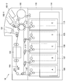
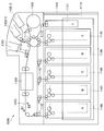
- FIG. 1 is a configuration diagram of a main part of a general cash processing apparatus 90.
- the cash processing apparatus 90 may be an operation-type terminal that executes a money transaction based on an operation by an operator such as a reception counter member of a financial institution.
- the cash processing apparatus 90 is installed in a sales office of a financial institution or the like.
- the cash processing apparatus 90 is a cash dispenser (TCR: Teller Cash Recycler) for a window is mainly assumed.
- the cash processing apparatus 90 includes a deposit port 101, a withdrawal port 102 (first withdrawal port 102-1, second withdrawal port 102-2), a conveyance path 103, and a recognition unit 104. , Temporary storage unit 105, bill cassettes 106 to 110, safe (reject box) 111, and blades 112 and 113.
- the banknote cassettes 106 to 110 mounted in the slots A to E are referred to as banknote cassettes A to E
- the safe 111 mounted in the slot F is referred to as a safe F. It may be described.
- the deposit port 101 is a slot into which bills are inserted by an operator.
- the deposit port 101 may be provided with a shutter (not shown) that opens and closes the opening. Further, the deposit port 101 may have a separation function of separating banknotes inserted in a bundle one by one and feeding them to the transport path 103.
- the deposit port 101 may be movable so that it can tilt toward the transport path 103 or tilt toward the take-out port by the operator.
- the withdrawal port 102 is a discharge port through which banknotes received by the operator are discharged.
- the withdrawal port 102 may be provided with a shutter (not shown) that opens and closes the opening.
- the withdrawal port 102 may have a stacking function for stacking the banknotes to be discharged.
- the dispensing port 102 may be movable so as to be inclined toward the conveyance path 103 or inclined toward the take-out port by the operator.
- the positions of the first withdrawal port 102-1 and the second withdrawal port 102-2 in the cash processing apparatus 90 are not particularly limited.
- the conveyance path 103 has a function of conveying banknotes.
- a mechanism may be used in which banknotes are sandwiched and sent between a plurality of rollers that face and abut against each other.
- the conveyance path 103 can be driven by a drive motor (not shown).
- the drive motor (not shown) is configured by, for example, a DC servo motor or a pulse motor, and drives the conveyance path 103 by rotating the motor.
- a drive motor drives the conveyance path 103 so that the conveyance path 103 conveys a banknote to the target conveyance destination according to control of the control part (not shown) which controls the operation
- the conveyance path 103 may be divided into a plurality of conveyance sections, and the plurality of conveyance sections may be driven by respective drive motors.
- the blades 112 and 113 are disposed at a branch portion of the transport path 103 and control the transport direction of the banknotes according to the control of a control unit (not shown). For example, the blades 112 and 113 may control the banknote transport direction using a method in which a rotary solenoid is directly connected and rotated.
- the recognition unit 104 recognizes bills conveyed one by one.
- the recognition part 104 can recognize the banknote conveyed in both directions (direction D1 and direction D2). Specifically, the recognition unit 104 discriminates the denomination, authenticity, correctness, running state, and the like of the banknotes conveyed by the conveyance path 103, and performs normality determination or abnormality determination on the conveyed banknotes. .
- the abnormality determination is performed based on factors such as authenticity, correctness (stained, damaged, external shape abnormality, etc.), running abnormality (skew bill, heavy running, etc.).
- abnormal banknotes hereinafter also referred to as “reject banknotes” may include two thousand yen bills and five thousand yen bills that cannot be handled as withdrawal banknotes, or may include foreign banknotes.
- the temporary storage unit 105 has both functions of separating and storing banknotes.
- the temporary storage unit 105 temporarily stores banknotes that are separated from the deposit port 101 at the time of depositing and recognized as normal by the recognition unit 104.
- the banknotes stored in the temporary holding unit 105 are paid out when a transaction is established (for example, when account recording of the deposited banknote is confirmed) and conveyed to the recognition unit 104.
- the paper is conveyed to the bill cassettes A to D through the recognition unit 104.
- the storage format of the temporary storage unit 105 may be an accumulation type in which banknotes are sequentially stacked and accumulated, or may be a drum type in which banknotes are sequentially wound and stored.
- the banknote cassettes A to D can store banknotes for each denomination and have both banknote storage and separation functions.
- the banknote cassettes A to D may include banknote cassettes that store banknotes of the same denomination.
- the banknote cassettes A and C may store 10,000 yen bills
- the banknote cassettes B and D may store thousand yen bills.
- the banknote cassettes A to D may be structured to be detachable from the cash processing apparatus 90.
- the banknote cassette E has a storing function for storing banknotes and a separating function for feeding one by one.
- the bill cassette E can store bills separated from the bill cassettes A to D at the time of collection.
- the banknote cassette E can feed banknotes stored at the time of replenishment and replenish banknotes A to D with banknotes.
- the banknote cassette E can be used for a plurality of applications.
- the banknote cassette E may be a structure which can be attached or detached with respect to the cash processing apparatus 90. FIG.
- the safe box F has a storage function for storing banknotes.
- the deposit box F has a function of storing banknotes (reject banknotes) recognized as abnormal by the recognition unit 104.
- the bank safe F is a multipurpose banknote cassette (bank safe) that can store banknotes that are variously distinguished from other banknotes such as normal banknotes, foreign banknotes, counterfeits, etc. in addition to reject banknotes. It may be.
- the safe box F may be structured to be detachable from the cash processing apparatus 90.
- Transactions can include depositing, storing, withdrawing, replenishing, collecting, and the like.
- banknotes inserted into the deposit port 101 by the operator are conveyed one by one along the direction D1 to the recognition unit 104 by the conveyance path 103.
- the banknote recognized by the recognition unit 104 as a reject banknote is conveyed to the withdrawal port 102 along the direction D1.
- the bills conveyed to the withdrawal port 102 can be recognized again by the recognition unit 104 by being inserted again into the deposit port 101.
- the banknote recognized as normal by the recognition unit 104 is transported to the temporary storage unit 105 along the direction D ⁇ b> 2 and temporarily stored by the temporary storage unit 105.
- the deposit amount is displayed by a host system (not shown) that controls the cash processing apparatus 90.
- the operation of the cash processing apparatus 90 is shifted from the deposit operation to the storing operation in accordance with the storing start instruction of the host system (not shown).
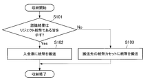
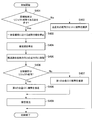
- FIG. 2 is a flowchart showing an example of the operation flow during the storing operation of a general cash processing apparatus 90.
- banknotes stored in the temporary storage unit 105 are conveyed to the recognition unit 104 by the conveyance path 103 along the direction D1 one by one.
- the recognition result by the recognition unit 104 indicates that the banknote is a reject banknote (“Yes” in step S101)
- the banknote is transported to the safe deposit box F along the direction D1 by the transport path 103 (step S102).
- step S101 when the recognition result by the recognition unit 104 indicates normal (“No” in step S101), the banknote is denominated in the banknote cassettes A to E by the transport path 103 along the direction D1. Are transferred to the bill cassette in which the denomination coincides with (step S103).
- the operation of the cash processing apparatus 90 may be shifted from the payment operation to the return operation in accordance with a return (cancellation) instruction of a host system (not shown).
- the banknotes stored in the temporary storage unit 105 are conveyed one by one along the direction D1 to the recognition unit 104 by the conveyance path 103, and the conveyance path 103 along the direction D1 regardless of the recognition result by the recognition unit 104. May be conveyed to the withdrawal port 102.
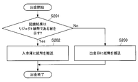
- FIG. 3 is a flowchart illustrating an example of an operation flow when the general cash processing apparatus 90 is withdrawn.
- a specified number of banknotes are separated one by one from a banknote cassette in which a specified denomination is set among banknote cassettes A to E, and are conveyed by a conveyance path 103 along a direction D2. It is conveyed to the recognition unit 104.
- the recognition result by the recognition unit 104 indicates that the banknote is a reject banknote (“Yes” in step S201)
- the banknote is transported to the safe deposit box F along the direction D2 by the transport path 103 (step S202).
- step S201 when the recognition result by the recognition unit 104 indicates normal ("No" in step S201), the banknote is conveyed to the withdrawal port 102 by the conveyance path 103 along the direction D2 (step S203). .
- the flow of banknotes when replenishing a general cash processing apparatus 90 will be described.
- the bill replenishment method include insertion port replenishment, cassette replacement replenishment, and cassette count replenishment.
- the charging port replenishment operation can be performed in the same manner as the depositing operation and the storing operation described above.
- exchange replenishment is a technique which sets the banknote cassette in which the banknote was accommodated beforehand to the cash processing apparatus 90, in this technique, since the recognition part 104 does not perform the counting process of a banknote, an operator is a banknote. It is necessary to manually register the denomination and number of sheets.
- the banknote recognized as normal is fed out from the temporary storage unit 105 and conveyed to the recognition unit 104 by the conveyance path 103 along the direction D1.
- the recognition result by the recognition part 104 shows that it is a reject banknote
- the said banknote is conveyed to the entrance safe F along the direction D1.
- the banknote recognized as normal by the recognition unit 104 is transported along the direction D1 to the banknote cassette in which the denomination matching the banknote denomination of the banknote is set by the transport path 103. Is done.
- the flow of banknotes when the general cash processing apparatus 90 is collected will be described.
- the bill collection method include withdrawal port collection, cassette exchange collection, and cassette count collection.
- the withdrawal port collection operation can be performed in the same manner as the above-described withdrawal operation.
- recovery is a method of removing a banknote cassette from the cash processing apparatus 90 and collect
- banknotes separated one by one from the banknote cassettes A to D are transported to the recognition unit 104 by the transport path 103 along the direction D2.
- the reject banknote recognized as abnormal by the recognition unit 104 is conveyed to the safe deposit box F along the direction D2.
- the banknote recognized as normal by the recognition part 104 is conveyed to the banknote cassette E along the direction D2.
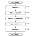
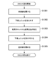
- FIG. 4 is a flowchart showing an example of an operator's work flow when a general cash processing apparatus 90 collects a cassette.
- the operator opens the safe door 115 using a key (step S301).
- the operator removes the lower unit 114 from the cash processing apparatus 90 (step S302), and removes the banknote cassette from the cash processing apparatus 90.
- the operator extracts the banknote from the removed banknote cassette (step S303), attaches the lower unit 114 to the cash processing apparatus 90 (step S304), and closes the safe door (step S305).
- banknote cassettes A to D can be recycling cassettes.
- the number of bills stored in the recycling cassette at the transport destination has reached the upper limit, it is common for the bills to be transported to the bill cassette set in the safe. is there.
- the bill cassette E can be a loading and collecting container.
- non-recyclable banknotes there may be banknotes (hereinafter referred to as “non-recyclable banknotes”) that are not targeted for withdrawal after being stored in the banknote cassette.
- banknotes of denominations that do not have banknote cassettes with matching denominations in the banknote cassettes A to E can be handled as non-recyclable banknotes. It is common for banknotes that are not recyclable to be transported to a banknote cassette that is set in the safe at the time of storage operation.
- the cash handling apparatus 90 is opened by opening the safe door 115 of the cash processing apparatus 90.
- the banknote cassette set in the bank safe F or the bank safe must be removed. Therefore, there is a possibility that the operator is forced to perform complicated work for collecting banknotes.
- the bank does not pay a request fee to another company in order to obtain a key for opening the safe door 115.
- the bank handling the cash processing apparatus 90 is charged a request fee for obtaining a key.
- the present specification mainly proposes a technique capable of reducing the possibility of forcing the operator to perform complicated work for collecting banknotes.
- the banknote cassettes A to E are arranged so as to be radially connected to the loop-shaped transport path 103, and the banknote cassettes A to E along the direction D2 that is the transport direction at the time of withdrawal.
- E, the recognition unit 104, and the safe deposit F are arranged in order.
- the banknotes separated from the banknote cassettes A to E and transported to the recognition unit 104 along the direction D2 are recognized as reject banknotes by the recognition unit 104, the banknotes are inserted into the safe box F.
- the advantage of being able to transport directly to the vehicle can be enjoyed.
- FIG. 5 is a main part configuration diagram of the cash processing apparatus 10 according to the embodiment of the present invention. The structure of the cash processing apparatus 10 which concerns on embodiment of this invention is demonstrated referring FIG.
- the bank safe F In the general cash processing apparatus 90, the bank safe F is used, but in the cash processing apparatus 10 according to the embodiment of the present invention, the bank safe F may not be used. Therefore, as shown in FIG. 5, the cash processing apparatus 10 according to the embodiment of the present invention does not have to include the deposit box F. However, since it is not necessary to use the safe deposit box F, it is needless to say that the cash processing apparatus 10 according to the embodiment of the present invention may include the safe deposit box F.
- FIG. 6 is a block diagram illustrating a functional configuration example of the cash processing apparatus 10 according to the embodiment of the present invention.
- the cash processing apparatus 10 includes a control unit 210, a detection unit 220, a storage unit 230, and a transport unit 240.
- the control unit 210 controls the overall operation of the cash processing apparatus 10. Specifically, the control unit 210 controls basic processes such as the deposit process, the withdrawal process, the replenishment process, and the collection process described above. For example, the control unit 210 controls the conveyance of banknotes by the conveyance unit 240 and the opening / closing operation of a shutter (not shown).
- the detection unit 220 includes, for example, an optical sensor and detects various states. For example, the detection unit 220 collects banknotes in the deposit port 101 and the withdrawal port 102 (the first withdrawal port 102-1 and the second withdrawal port 102-2) (the number of stacked sheets and the banknotes are extracted). Or not). Moreover, the detection part 220 can detect the conveyance state of a banknote. The result detected by the detection unit is output to the control unit 210.
- the storage unit 230 stores a program for operating the cash processing apparatus 10 and various data. In addition, the storage unit 230 can store the discrimination result of the recognition unit 104.
- the transport unit 240 is configured by the transport path 103 and has a function of transporting banknotes under the control of the control unit 210.
- the functions of the control unit 210 and the storage unit 230 may be realized by a hardware configuration including a CPU (Central Processing Unit), a ROM (Read Only Memory), a RAM (Random Access Memory), and the like.
- the CPU has a calculation function and a control function, and controls the overall operation of the cash processing apparatus 10 according to various programs.
- the ROM stores programs and calculation parameters used by the CPU.
- the RAM temporarily stores programs used in the execution of the CPU, parameters that change as appropriate during the execution, and the like.
- the control unit 210 controls the transport path 103 so that the banknote is transported to the withdrawal port 102.
- the banknote is not stored in the banknote cassette set in the deposit box F or the deposit box. Therefore, it is not necessary to open the safe door 115 of the cash processing apparatus 10 and pull out the lower unit 114 of the cash processing apparatus 10 and then remove the banknote cassette set in the safe deposit F or the safe deposit box. Therefore, the possibility of forcing the operator to perform complicated work for collecting banknotes is reduced.
- the first embodiment of the present invention relates to a bill storing operation after depositing is completed in the cash processing apparatus 10. Specifically, when the storing operation is started in the state where the deposit is completed and the banknotes are stored in the temporary storage unit 105, the banknotes are separated from the temporary storage unit 105 and fed out one by one. At this time, when the banknote separated from the temporary storage unit 105 is recognized as a reject banknote by the recognition unit 104, the control unit 210 causes the banknote to be conveyed to the withdrawal port 102.
- the control unit 210 may stop the separation of the banknote from the temporary storage unit 105. If it does so, it can prevent that a banknote is drawn
- FIG. Moreover, the conveyance direction of the conveyance path 103 is not specifically limited. For example, when the storage operation is started, the controller 210 may control the transport path 103 so that the transport direction is the direction D1. On the other hand, the control part 210 should just control the conveyance path 103 so that a conveyance direction may become the direction D2, when a reject banknote is recognized.
- the control unit 210 may convey the banknote to the banknote cassettes A to D.
- the control unit 210 uses a banknote cassette in which the same denomination as that of the banknote recognized by the recognition unit 104 among the banknote cassettes A to D is set as the transport destination of the normal banknote. Just decide.
- the withdrawal port 102 of the banknote transport destination is not particularly limited.
- the withdrawal port 102 of the banknote transport destination may be the first withdrawal port 102-1 or the second withdrawal port 102-2.
- the control unit 210 may cause the plurality of banknotes remaining in the conveyance path 103 to be conveyed to the withdrawal port 102.
- the control unit 210 selects a dispensing port 102 as a conveyance destination of a plurality of banknotes remaining in the conveyance path 103 according to the situation. May be.
- the control unit 210 is recognized as normal by the recognition unit 104 among the plurality of banknotes remaining in the conveyance path 103.
- the banknotes that have been recognized as reject banknotes by the recognition unit 104 may be transported to the second withdrawal port 102-2.
- FIG. 7 is a flowchart showing an example of an operation flow during the storing operation of the cash processing apparatus 10 according to the first embodiment of the present invention.
- the control unit 210 recognizes the banknote separated from the temporary storage unit 105 by the recognition unit 104 and indicates that the recognition result is a normal banknote (step S401). In "No"), the banknote is transported to the banknote cassette of the transport destination (step S402), and the storing operation is terminated. On the other hand, when the banknote separated from the temporary storage unit 105 is recognized by the recognition unit 104 and the recognition result indicates that the banknote is rejected (“Yes” in step S401), the control unit 210 temporarily stores the banknote 105. The separation of banknotes is stopped (step S403).
- control unit 210 stops the conveyance path 103 (step S404). Since separation of the banknote from the temporary storage unit 105 is stopped, it is possible to prevent the banknote from being broken by stopping the conveyance path 103. Note that the controller 210 may stop the entire transport path 103 or may stop a part of the transport path 103. For example, when the control unit 210 stops a part of the transport path 103, the control unit 210 may stop the transport path 103 between the temporary storage unit 105 and the blade 113 existing at the branching portion to the temporary storage unit 105. Good.
- control unit 210 moves the transport path 103 in a direction (direction D2) opposite to the storage direction (direction D1) (step S405). Subsequently, the control unit 210 sequentially determines whether or not the plurality of banknotes remaining in the transport path 103 are reject banknotes (step S406), and when the banknotes are normal banknotes ("No" in step S406). Then, the banknote is conveyed to the first withdrawal slot 102-1 (step S407), and when the banknote is a reject banknote (“Yes” in step S406), the banknote is transported to the second withdrawal slot 102-2. (Step S408).
- control unit 210 may place the cash processing apparatus 10 in a failure state (step S409) and end the storing operation.
- the failure state of the cash processing apparatus 10 is not particularly limited, the operation may be stopped until the operator performs a return operation on the cash processing apparatus 10.
- the selection method of the withdrawal port 102 of the conveyance destination of the some banknote remaining on the conveyance path 103 is not limited to this example.
- the control unit 210 causes the plurality of banknotes remaining in the conveyance path 103 to be conveyed to the first withdrawal port 102-1.
- the remaining banknotes may be conveyed to the second withdrawal port 102-2.
- Such an upper limit value is not particularly limited, and may be appropriately set according to the size of the first withdrawal port 102-1.
- the second embodiment of the present invention relates to a withdrawal operation in the cash processing apparatus 10. Specifically, when a dispensing operation is started in a state where a plurality of banknotes are stored in the banknote cassette A, the banknotes are separated from the banknote cassette A one by one and fed out.
- the bill cassette A will be described, but bill cassettes B to E may be used instead of the bill cassette A.
- the control unit 210 causes the banknote to be conveyed to the withdrawal port 102.
- the control unit 210 may stop the separation of the banknote from the temporary storage unit 105. If it does so, it can prevent that a banknote will be drawn
- FIG. Moreover, the conveyance direction of the conveyance path 103 is not specifically limited. For example, when the dispensing operation is started, the control unit 210 may control the conveyance path 103 so that the conveyance direction becomes the direction D2. On the other hand, when the reject banknote is recognized, the control unit 210 may control the transport path 103 so that the transport direction remains the direction D2.
- the control unit 210 may cause the banknote to be conveyed to the withdrawal port 102.
- the withdrawal port 102 of the banknote transport destination is not particularly limited.
- the withdrawal port 102 of the banknote transport destination may be the first withdrawal port 102-1 or the second withdrawal port 102-2.
- the control unit 210 selects a dispensing port 102 as a conveyance destination of a plurality of banknotes remaining in the conveyance path 103 according to the situation. May be.
- the control unit 210 is recognized as normal by the recognition unit 104 among the plurality of banknotes remaining in the conveyance path 103.
- the banknotes that have been recognized as reject banknotes by the recognition unit 104 may be transported to the second withdrawal port 102-2.
- FIG. 8 is a flowchart illustrating an example of an operation flow when the cash processing apparatus 10 according to the second embodiment of the present invention makes a withdrawal.
- the control unit 210 recognizes the banknote separated from the banknote cassette A by the recognition unit 104 and indicates that the recognition result is a normal banknote (in step S501). “No”), the banknote is conveyed to the withdrawal port 102 (step S502), and the storing operation is terminated.
- the control section 210 determines the banknote in the banknote cassette A. Is separated (step S503).
- control unit 210 stops the conveyance path 103 (step S504). Since the separation of the banknote from the banknote cassette A is stopped, the banknote can be prevented from being broken by stopping the conveyance path 103. Note that the controller 210 may stop the entire transport path 103 or may stop a part of the transport path 103. For example, when a part of the conveyance path 103 is stopped, the control unit 210 may stop the conveyance path 103 between the banknote cassette A and the blade 112 existing at a branching portion to the banknote cassette A.
- control unit 210 moves the transport path 103 in the withdrawal direction (direction D2) (step S505). Subsequently, the control unit 210 sequentially determines whether or not the plurality of banknotes remaining in the transport path 103 are reject banknotes (step S506), and when the banknote is a normal banknote ("No" in step S506). Then, the banknote is conveyed to the first withdrawal port 102-1 (step S507), and when the banknote is a reject bill (“Yes” in step S506), the banknote is transferred to the second withdrawal port 102-2. (Step S508).
- control unit 210 may place the cash processing apparatus 10 in a failure state (step S509) and end the withdrawal operation.
- the failure state of the cash processing apparatus 10 is not specifically limited.
- the selection method of the withdrawal port 102 of the conveyance destination of the some banknote remaining on the conveyance path 103 is not limited to this example.
- the control unit 210 causes the plurality of banknotes remaining in the conveyance path 103 to be conveyed to the first withdrawal port 102-1.
- the remaining banknotes may be conveyed to the second withdrawal port 102-2.
- Such an upper limit value is not particularly limited, and may be appropriately set according to the size of the first withdrawal port 102-1.
- the third embodiment of the present invention relates to a bill storing operation after depositing is completed in the cash processing apparatus 10. Specifically, when the storing operation is started in the state where the deposit is completed and the banknotes are stored in the temporary storage unit 105, the banknotes are separated from the temporary storage unit 105 and fed out one by one. At this time, when the transport destination of the banknote separated from the temporary storage section 105 and recognized by the recognition section 104 is other than the recycling cassette, the control section 210 transports the banknote to the withdrawal port 102.
- the bill types of banknote cassettes A to E are (in order of denomination 100 yuan, issuance 2005), (denomination 50 yuan, issuance 2005), (denomination 100 yuan, issuance 1999), (denomination 50 yuan, issuance 1999) and (denomination 20 yuan, issuance 2005).
- banknote cassettes A to E are ordered in order of (denomination 100 yuan), (denomination 50 yuan), (denomination 10,000 yen), (denomination 5,000 yen), and (gold Yen thousand yen).
- the control unit 210 causes the banknote 102 to be conveyed. More specifically, when the denomination of the banknote separated from the temporary storage unit 105 and recognized by the recognition unit 104 does not match the denomination set in the recycling cassette, the control unit 210 removes the banknote from the withdrawal port. 102 may be conveyed.
- the transport destination of the banknotes separated from the temporary storage unit 105 and recognized by the recognition unit 104 is the recycling cassette, but the number of banknotes stored in the recycling cassette reaches the upper limit value. If so, the banknote is conveyed to the withdrawal port 102. More specifically, when the denomination of the banknote separated from the temporary storage unit 105 and recognized by the recognition unit 104 matches the denomination set in the recycling cassette, and the number of banknotes stored in the recycling cassette May reach the upper limit, the banknote may be conveyed to the withdrawal port 102.
- the control unit 210 may stop the separation of the banknote from the temporary storage unit 105 when the transport destination of the banknote separated from the temporary storage unit 105 is not a recycling cassette. If it does so, it can prevent that a banknote is drawn
- FIG. Moreover, the conveyance direction of the conveyance path 103 is not specifically limited. For example, when the storage operation is started, the controller 210 may control the transport path 103 so that the transport direction is the direction D1. On the other hand, the control part 210 should just control the conveyance path 103 so that a conveyance direction may become the direction D2, when the conveyance destination of a banknote is not a recycle cassette.
- the control section 210 may transport the banknote to the recycling cassette.
- the control unit 210 determines, among the banknote cassettes A to D, a banknote cassette in which the same denomination as that of the banknote recognized by the recognition unit 104 is set as the transport destination of the banknote. Then, it may be determined whether or not the determined transport destination is a recycling cassette.
- the withdrawal port 102 of the banknote transport destination is not particularly limited.
- the withdrawal port 102 of the banknote transport destination may be the first withdrawal port 102-1 or the second withdrawal port 102-2.
- the control unit 210 may cause a plurality of banknotes remaining in the transport path 103 to be transported to the withdrawal port 102 when it is determined that the transport destination of the banknote being transported is a recycling cassette.
- the control unit 210 selects the plurality of banknote transport destinations 102 remaining in the transport path 103 according to the situation. Good. For example, when the control unit 210 determines that the transport destination of the banknote being transported is a recycling cassette, the banknote recognized as normal by the recognition unit 104 among the plurality of banknotes remaining in the transport path 103. May be conveyed to the first withdrawal port 102-1, and the banknote recognized by the recognition unit 104 as a rejected banknote may be conveyed to the second withdrawal port 102-2.
- FIG. 9 is a flowchart showing an example of an operation flow during the storing operation of the cash processing apparatus 10 according to the third embodiment of the present invention.
- step S601 the control unit 210 recognizes the banknote separated from the temporary storage unit 105 by the recognition unit 104 and indicates that the recognition result is a normal banknote (step S601). In step S611, the process proceeds to step S611. On the other hand, when the banknote separated from the temporary storage unit 105 is recognized by the recognition unit 104 and the recognition result indicates that the banknote is rejected (“Yes” in step S601), the control unit 210 proceeds to step S603. . Steps S603 to S608 shown in FIG. 9 can be executed in the same manner as steps S403 to S408 shown in FIG.
- control unit 210 determines whether the transport destination of the banknote being transported is a recycling cassette (step S611).
- the controller 210 transports the banknote to the recycle cassette (step S612) and ends the storing operation.
- the control unit 210 stops the separation of banknotes in the temporary storage unit 105 (step S613). Further, the controller 210 stops the conveyance path 103 (step S614). Since separation of the banknote from the temporary storage unit 105 is stopped, it is possible to prevent the banknote from being broken by stopping the conveyance path 103. Note that the controller 210 may stop the entire transport path 103 or may stop a part of the transport path 103. For example, when the control unit 210 stops a part of the transport path 103, the control unit 210 may stop the transport path 103 between the temporary storage unit 105 and the blade 113 existing at the branching portion to the temporary storage unit 105. Good.
- control unit 210 moves the transport path 103 in a direction (direction D2) opposite to the storage direction (direction D1) (step S615). Subsequently, the control unit 210 sequentially determines whether or not the plurality of banknotes remaining in the transport path 103 are reject banknotes (step S616), and when the banknote is a normal banknote ("No" in step S616). Then, the banknote is conveyed to the first withdrawal port 102-1 (step S617), and when the banknote is a reject bill (“Yes” in step S616), the banknote is transferred to the second withdrawal port 102-2. (Step S618).
- control unit 210 may place the cash processing apparatus 10 in a failure state (step S619) and end the storing operation.
- the failure state of the cash processing apparatus 10 is not specifically limited.
- the selection method of the withdrawal port 102 of the conveyance destination of the some banknote remaining on the conveyance path 103 is not limited to this example.
- the control unit 210 determines that the transport destination of the banknote being transported is a recycling cassette, the control unit 210 transports the plurality of banknotes remaining in the transport path 103 to the first withdrawal port 102-1, When the number of banknotes conveyed to one withdrawal port 102-1 reaches the upper limit value, the remaining banknotes may be conveyed to the second withdrawal port 102-2.
- Such an upper limit value is not particularly limited, and may be appropriately set according to the size of the first withdrawal port 102-1.
- control unit 210 for controlling the entire operation of the cash processing apparatus 10 may be configured by dedicated hardware, or the CPU built in the cash processing apparatus 10 stores the program stored in the ROM in the RAM. It may be realized by expanding and executing. In addition to providing such a program, a storage medium storing such a program may also be provided.
- the cash processing apparatus 10 by this embodiment is not limited to this.
- the present invention may be applied to a cash processing unit of an automatic transaction apparatus represented by an ATM of a customer operation type terminal that recycles (recycles) banknotes.
- Automatic transaction apparatuses are installed in various places such as banks, station premises, and convenience stores. The customer can perform transactions such as deposit, withdrawal and balance inquiry by performing various operations on the display screen displayed on the automatic transaction apparatus.
- Second invention The present invention can be implemented in various forms. Moreover, the cash processing apparatus (1010) by 2nd invention demonstrated below is A. Withdrawal port (1102) through which banknotes are discharged, A recognizing unit (1104) for recognizing whether the banknote is normal; B. A bill storage (1106 to 1110) capable of storing and dispensing bills; C. A transport unit (1103) for transporting banknotes; D. When rejected banknotes are generated during the conveyance of banknotes, the banknote conveyance operation is stopped and a failure occurrence is notified, and then the banknotes remaining in the conveyance path are transferred to the withdrawal port by reset processing. A control unit (CPU 1040) to control; Have
- FIG. 10 is a main part configuration diagram of a general cash processing apparatus 1090.
- the cash processing apparatus 1090 may be an operation-type terminal that executes a money transaction based on an operation by an operator such as a reception counter of a financial institution. Further, for example, the cash processing apparatus 1090 is installed at a financial institution or the like. Below, the case where the cash processing apparatus 1090 is a cash cash dispenser (TCR: Teller Cash Recycler) is mainly assumed.
- TCR Teller Cash Recycler
- the cash processing apparatus 1090 includes a deposit port 1101, a withdrawal port 1102 (first withdrawal port 1102-1, second withdrawal port 1102-2), a conveyance path 1103, a recognition unit 1104. , Temporary storage unit 1105, bill cassettes 1106 to 1110, safe (reject box) 1111, and blades 1112 and 1113.
- the banknote cassettes 1106 to 1110 installed in the slots A to E are referred to as banknote cassettes A to E
- the safe 1111 installed in the slot F is referred to as the safe safe F. It may be described.
- the deposit port 1101 is a slot into which bills are inserted by the operator.
- the deposit port 1101 may be provided with a shutter (not shown) that opens and closes the opening. Further, the deposit port 1101 may have a separation function of separating banknotes inserted in a bundle one by one and feeding them out to the transport path 1103.
- the deposit port 1101 may be movable so that it can be tilted toward the conveyance path 1103 or tilted toward the take-out port by the operator.
- the withdrawal port 1102 is a discharge port through which banknotes received by the operator are discharged.
- the withdrawal port 1102 may be provided with a shutter (not shown) that opens and closes the opening. Further, the withdrawal port 1102 may have a stacking function for stacking banknotes to be discharged. Note that the dispensing port 1102 may be movable so that it can be tilted toward the conveyance path 1103 or tilted toward the take-out port by the operator.
- the withdrawal port 1102 may include a first withdrawal port 1102-1 and a second withdrawal port 1102-2. The positions of the first withdrawal port 1102-1 and the second withdrawal port 1102-2 in the cash processing apparatus 1090 are not particularly limited.
- the conveyance path 1103 has a function of conveying banknotes.
- a mechanism may be used in which banknotes are sandwiched and sent between a plurality of rollers that face and abut against each other.
- the conveyance path 1103 can be driven by a drive motor (not shown).
- the drive motor (not shown) is constituted by, for example, a DC servo motor or a pulse motor, and drives the conveyance path 1103 by rotating the motor.
- a drive motor drives the conveyance path 1103 so that the conveyance path 1103 conveys banknotes to a target conveyance destination according to control of a control unit (not shown) that controls the overall operation of the cash processing apparatus 1090.
- the conveyance path 1103 may be divided into a plurality of conveyance sections, and the plurality of conveyance sections may be driven by respective drive motors.
- the blades 1112 and 1113 are arranged at a branch portion of the conveyance path 1103 and control the conveyance direction of the bills according to control of a control unit (not shown). For example, the blades 1112 and 1113 may control the banknote transport direction using a method in which a rotary solenoid is directly connected and rotated.
- the recognition unit 1104 recognizes bills conveyed one by one.
- the recognizing unit 1104 can recognize a banknote conveyed in both directions (direction D1 and direction D2). Specifically, the recognition unit 1104 discriminates the denomination, authenticity, correctness, running state, and the like of the banknote conveyed by the conveyance path 1103, and performs normality determination or abnormality determination on the conveyed banknote. .
- the abnormality determination is performed based on factors such as authenticity, correctness (stained, damaged, external shape abnormality, etc.), running abnormality (skew bill, heavy running, etc.).
- abnormal banknotes hereinafter also referred to as “reject banknotes” may include two thousand yen bills and five thousand yen bills that cannot be handled as withdrawal banknotes, or may include foreign banknotes.
- the temporary storage unit 1105 has both functions of separating and storing banknotes.
- the temporary storage unit 1105 temporarily stores bills that are separated from the deposit port 1101 at the time of depositing and recognized as normal by the recognition unit 1104.
- the banknotes stored in the temporary storage unit 1105 are fed out and transferred to the recognition unit 1104 when a transaction is established (for example, when the account of the deposited banknote is confirmed).
- the paper is conveyed to the bill cassettes A to D through the recognition unit 1104.
- the storage form of the temporary storage unit 1105 may be an accumulation type in which banknotes are sequentially stacked and accumulated, or may be a drum type in which banknotes are wound and stored in sequence.
- the banknote cassettes A to D can store banknotes for each denomination and have both banknote storage and separation functions.
- the banknote cassettes A to D may include banknote cassettes that store banknotes of the same denomination.
- the banknote cassettes A and C may store 10,000 yen bills
- the banknote cassettes B and D may store thousand yen bills.
- the banknote cassettes A to D may be configured to be detachable from the cash processing apparatus 1090.
- the banknote cassette E has a storing function for storing banknotes and a separating function for feeding one by one.
- the bill cassette E can store bills separated from the bill cassettes A to D at the time of collection.
- the banknote cassette E can feed banknotes stored at the time of replenishment and replenish banknotes A to D with banknotes.
- the banknote cassette E can be used for a plurality of applications.
- the banknote cassette E may be a structure which can be attached or detached with respect to the cash processing apparatus 1090. FIG.
- the safe box F has a storage function for storing banknotes.
- the deposit box F has a function of storing banknotes (reject banknotes) recognized as abnormal by the recognition unit 1104.
- the bank safe F is a multipurpose banknote cassette (bank safe) that can store banknotes that are variously distinguished from other banknotes such as normal banknotes, foreign banknotes, counterfeits, etc. in addition to reject banknotes. It may be.
- the safe box F may be structured to be detachable from the cash processing apparatus 1090.
- Transactions can include depositing, storing, withdrawing, replenishing, collecting, and the like.
- banknotes inserted into the deposit port 1101 by the operator are conveyed one by one along the direction D1 to the recognition unit 1104 along the conveyance path 1103.
- the banknote recognized as a reject banknote by the recognition unit 1104 is conveyed to the withdrawal port 1102 along the direction D1.
- the bills conveyed to the withdrawal port 1102 can be recognized again by the recognition unit 1104 by being inserted into the deposit port 1101 again.
- the banknote recognized as normal by the recognition unit 1104 is transported to the temporary storage unit 1105 along the direction D1, and is temporarily stored by the temporary storage unit 1105.
- the deposit amount is displayed by a host system (not shown) that controls the cash processing apparatus 1090.
- the operation of the cash processing apparatus 1090 is shifted from the deposit operation to the store operation in accordance with a store start instruction from the host system (not shown).
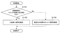
- FIG. 11 is a flowchart showing an example of a flow of operations during a storing operation of a general cash processing apparatus 1090.
- banknotes stored in the temporary storage unit 1105 are conveyed to the recognition unit 1104 by the conveyance path 1103 along the direction D1 one by one.
- the recognition result by the recognition unit 1104 indicates that the banknote is a reject banknote (“Yes” in step S11101)
- the banknote is transported to the safe deposit box F along the direction D1 by the transport path 1103 (step S11102).
- step S11101 if the recognition result by the recognition unit 1104 indicates normal (“No” in step S11101), the banknote is denominated in the banknote cassettes A to E by the transport path 1103 along the direction D1. Are transferred to the bill cassette in which the denomination coincides with (step S11103).
- the operation of the cash processing apparatus 1090 may be shifted from the deposit operation to the return operation in accordance with a return (cancel) instruction of a host system (not shown).
- a return (cancel) instruction of a host system not shown.
- banknotes stored in the temporary storage unit 1105 are conveyed one by one along the direction D1 by the conveyance path 1103 to the recognition unit 1104, and the conveyance path 1103 along the direction D1 regardless of the recognition result by the recognition unit 1104. May be conveyed to the withdrawal port 1102.
- FIG. 12 is a flowchart illustrating an example of an operation flow when the general cash processing apparatus 1090 is withdrawn.
- a designated number of banknotes are separated one by one from a banknote cassette in which a designated denomination is set among the banknote cassettes A to E, and are conveyed by a conveyance path 1103 along a direction D2. It is conveyed to the recognition unit 1104.
- the recognition result by the recognition unit 1104 indicates that the banknote is a reject banknote (“Yes” in step S1201)
- the banknote is transported to the safe deposit box F along the direction D2 by the transport path 1103 (step S1202).
- step S1201 when the recognition result by the recognition unit 1104 indicates normal (“No” in step S1201), the banknote is transported to the withdrawal port 1102 by the transport path 1103 along the direction D2 (step S1203). .
- the flow of banknotes when a general cash processing apparatus 1090 is replenished will be described.
- the bill replenishment method include insertion port replenishment, cassette replacement replenishment, and cassette count replenishment.
- the charging port replenishment operation can be performed in the same manner as the depositing operation and the storing operation described above.
- exchange replenishment is the method of setting the banknote cassette in which the banknote was accommodated beforehand to the cash processing apparatus 1090, in this technique, since the recognition part 1104 does not perform the counting process of a banknote, an operator It is necessary to manually register the denomination and number of sheets.
- the banknotes separated from the banknote cassette E one by one are transported to the recognition unit 1104 by the transport path 1103 along the direction D2.
- the recognition result by the recognition unit 1104 indicates that the banknote is a reject banknote
- the banknote is conveyed to the safe deposit box F along the direction D2.
- the recognition result by the recognition unit 1104 indicates that the recognition result is normal
- the banknote is conveyed to the temporary storage unit 1105 by the conveyance path 1103 along the direction D2.
- the banknote recognized as normal is fed out from the temporary storage unit 1105 and conveyed to the recognition unit 1104 by the conveyance path 1103 along the direction D1.
- the recognition result by the recognition unit 1104 indicates that the banknote is a reject banknote
- the banknote is conveyed to the safe deposit box F along the direction D1.
- the banknote recognized as normal by the recognition unit 1104 is transported along the direction D1 to the banknote cassette in which the denomination matching the banknote denomination of the banknote cassette A to E is set by the transport path 1103. Is done.
- the flow of banknotes when collecting a general cash processing apparatus 1090 will be described.
- Examples of the bill collection method include withdrawal port collection, cassette exchange collection, and cassette count collection.
- the withdrawal port collection operation can be performed in the same manner as the above-described withdrawal operation.
- the cassette exchange recovery is a technique for removing the banknote cassette from the cash processing apparatus 1090 and collecting the banknote.
- the counting unit of the banknote is not executed by the recognition unit 1104. It is a common operation to extract banknotes from a banknote cassette and manually count the denomination and number of banknotes.
- the banknotes separated one by one from the banknote cassettes A to D are transported to the recognition unit 1104 by the transport path 1103 along the direction D2.
- the reject banknote recognized as abnormal by the recognition unit 1104 is conveyed to the safe deposit box F along the direction D2.
- the banknote recognized as normal by the recognition unit 1104 is conveyed to the banknote cassette E along the direction D2.
- FIG. 13 is a flowchart showing an example of an operator's work flow when a general cash processing apparatus 1090 collects a cassette.
- the operator opens the safe door 1115 using a key (step S1301).
- the operator removes the lower unit 1114 from the cash processing apparatus 1090 (step S1302), and removes the banknote cassette from the cash processing apparatus 1090.
- the operator removes the banknote from the removed banknote cassette (step S1303), attaches the lower unit 1114 to the cash processing apparatus 1090 (step S1304), and closes the safe door (step S1305).
- banknote cassettes A to D can be recycling cassettes.
- the number of bills stored in the recycling cassette at the transport destination has reached the upper limit, it is common for the bills to be transported to the bill cassette set in the safe. is there.
- the bill cassette E can be a loading and collecting container.
- non-recyclable banknotes there may be banknotes (hereinafter referred to as “non-recyclable banknotes”) that are not targeted for withdrawal after being stored in the banknote cassette.
- banknotes of denominations that do not have banknote cassettes with matching denominations in the banknote cassettes A to E can be handled as non-recyclable banknotes. It is common for banknotes that are not recyclable to be transported to a banknote cassette that is set in the safe at the time of storage operation.
- the cash handling apparatus 1090 is opened by opening the safe door 1115 of the cash processing apparatus 1090.
- the lower unit 1114 is pulled out, it is necessary to remove the banknote cassette set in the deposit box F or the deposit box. Therefore, there is a possibility that the operator is forced to perform complicated work for collecting banknotes.
- the bank does not pay a request fee to another company to obtain a key for opening the safe door 1115.
- the bank does not pay a request fee to another company to obtain a key for opening the safe door 1115.
- an operator who handles the cash processing apparatus 1090 may be forced to perform complicated procedures.
- a bank handling the cash processing apparatus 1090 is charged a request fee for obtaining a key.
- the present specification mainly proposes a technique that can eliminate the need to open the safe door for collecting banknotes by discharging the remaining banknotes from the withdrawal port when rejected banknotes are generated. To do.
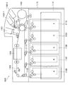
- FIG. 14 is a main part configuration diagram of the cash processing apparatus 1010 according to the embodiment of the present invention.
- the bank safe F is used, but in the cash processing apparatus 1010 according to the embodiment of the present invention, the bank safe F need not be used. Therefore, as shown in FIG. 14, the cash processing apparatus 1010 according to the embodiment of the present invention does not have to include the deposit box F. However, since it is not necessary to use the safe deposit box F, it is needless to say that the cash processing apparatus 1010 according to the embodiment of the present invention may include the safe deposit box F.
- FIG. 15 is a block diagram illustrating a functional configuration example of the cash processing apparatus 1010 according to the embodiment of the present invention.
- the cash processing apparatus 1010 according to the embodiment of the present invention includes a control unit 1210, a detection unit 1220, a storage unit 1230, and a transport unit 1240.
- Control unit 1210 controls the overall operation of cash processing apparatus 1010. Specifically, the control unit 1210 controls basic processes such as the above-described deposit process, withdrawal process, replenishment process, and collection process. For example, the control unit 1210 controls the conveyance of banknotes by the conveyance unit 1240 and the opening / closing operation of a shutter (not shown).
- the detection unit 1220 includes, for example, an optical sensor and detects various states. For example, the detection unit 1220 collects banknotes in the deposit port 1101 and the withdrawal port 1102 (the first withdrawal port 1102-1 and the second withdrawal port 1102-2) (the number of stacked sheets and the banknotes are extracted). Or not). Moreover, the detection part 1220 can detect the conveyance state of a banknote. The result detected by the detection unit is output to the control unit 1210.
- Storage unit 1230 stores a program for operating cash processing apparatus 1010, various data, and the like.
- the storage unit 1230 can store the discrimination result of the recognition unit 1104.
- the transport unit 1240 is configured by a transport path 1103 and has a function of transporting banknotes under the control of the control unit 1210.
- the functions of the control unit 1210 and the storage unit 1230 may be realized by a hardware configuration including a CPU (Central Processing Unit), a ROM (Read Only Memory), a RAM (Random Access Memory), and the like.
- the CPU has an arithmetic function and a control function, and controls the overall operation of the cash processing apparatus 1010 according to various programs.
- the ROM stores programs and calculation parameters used by the CPU.
- the RAM temporarily stores programs used in the execution of the CPU, parameters that change as appropriate during the execution, and the like.
- the control unit 1210 stops the operation of the transport path 1103 and notifies the occurrence of a failure
- the reset process is executed according to the instruction.
- the conveyance path 1103 is controlled so that the bills remaining on the conveyance path 1103 are conveyed to the withdrawal port 1102.
- the banknote is not stored in the banknote cassette set in the deposit box F or the deposit box.
- the first embodiment of the present invention relates to a bill storing operation after depositing is completed in the cash processing apparatus 1010. Specifically, when the storing operation is started in the state where the deposit is completed and the banknotes are stored in the temporary storage unit 1105, the banknotes are separated from the temporary storage unit 1105 and fed out one by one.
- the control unit 1210 stops the operation of the transport path 1103 and notifies the operator of the occurrence of the failure. Thereafter, in the reset process, the control unit 1210 controls the banknote to be conveyed to the withdrawal port 1102.
- the recognition unit 1104 recognizes that the banknote separated from the temporary storage unit 1105 is a rejected banknote
- the control unit 1210 stops the separation of the banknote from the temporary storage unit 1105. Thereby, it can prevent that a banknote is drawn out from the temporary storage part 1105 to the conveyance path 1103.
- the conveyance direction of the conveyance path 1103 is not specifically limited.
- the control unit 1210 controls the transport path 1103 so that the transport direction is the direction D1, and when the reject banknote is recognized, the transport direction is the direction D2.
- the conveyance path 1103 is controlled.
- the control unit 1210 conveys the banknote to the banknote cassettes A to D.
- the control unit 1210 uses a banknote cassette in which the same denomination as that of the banknote recognized by the recognition unit 1104 among the banknote cassettes A to D is set as the transport destination of the normal banknote. decide.
- the withdrawal port 1102 of the banknote transport destination is not particularly limited.
- the withdrawal port 1102 of the banknote transport destination may be the first withdrawal port 1102-1 or the second withdrawal port 1102-2.
- the control unit 1210 causes the plurality of banknotes remaining in the conveyance path 1103 to be conveyed to the withdrawal port 1102 in the reset process. This example will be specifically described with reference to FIGS.
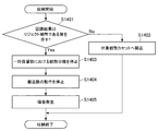
- FIG. 16 is a flowchart illustrating an example of an operation flow during the storing operation of the cash processing apparatus 1010 according to the first embodiment of the present invention.
- the control unit 1210 recognizes the banknote separated from the temporary storage unit 105 by the recognition unit 1104 and indicates that the recognition result is a normal banknote (step S1401). In “No”), the banknote is transported to the banknote cassette at the transport destination (step S1402).
- step S1403 if the banknote separated from the temporary storage unit 105 is recognized by the recognition unit 1104 and the recognition result indicates that the banknote is rejected (“Yes” in step S1401), the control unit 1210 temporarily stores the banknote 105. The separation of banknotes is stopped (step S1403).
- control unit 1210 stops the conveyance path 1103 (step S1404). Since the separation of the banknote from the temporary storage unit 1105 is stopped, the banknote can be prevented from being broken by stopping the conveyance path 1103. Note that the control unit 1210 may stop the entire transport path 1103 or may stop a part of the transport path 1103. For example, when the control unit 1210 stops a part of the transport path 1103, the control unit 1210 may stop the transport path 1103 between the temporary storage unit 1105 and the blade 1113 existing at the branching portion to the temporary storage unit 1105. Good.
- control part 1210 makes the cash processing apparatus 1010 into a failure state (step S1405), and complete
- the failure state of the cash processing apparatus 1010 is determined until the operator performs a return operation (specifically, a reset instruction) after notifying the operator (specifically, for example, a PC operated by the operator) of the failure. The operation is stopped.
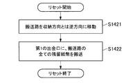
- FIG. 17 is a flowchart showing an example of an operation flow during the reset operation of the cash processing apparatus according to the first embodiment of the present invention.
- control unit 1210 When the control unit 1210 receives the reset instruction, the control unit 1210 moves the conveyance path 1103 in the direction (direction D2) opposite to the storage direction (direction D1) (step S1421).
- control unit 1210 transports all banknotes remaining on the transport path 1103 to the first withdrawal port 1102-1 (step S1422).
- the remaining banknotes are accumulated in the first withdrawal port 1102-1, and the operator can collect the remaining banknotes including the rejected banknotes from the withdrawal port 1102 without opening and closing the safe door.
- the transport destinations of the plurality of banknotes remaining in the transport path 1103 are not limited to the first withdrawal port 1102-1.
- the control unit 1210 causes a plurality of banknotes remaining in the transport path 1103 to be transported to the first withdrawal port 1102-1, and the upper limit is the number of banknotes transported to the first withdrawal port 1102-1. When the value is reached, the remaining banknotes may be conveyed to the second withdrawal port 1102-2.
- Such an upper limit is not particularly limited, and is appropriately set according to the size of the first withdrawal port 1102-1.
- the second embodiment of the present invention relates to a withdrawal operation of the cash processing apparatus 1010. Specifically, when a dispensing operation is started in a state where a plurality of banknotes are stored in the banknote cassette A, the banknotes are separated from the banknote cassette A one by one and fed out.
- the bill cassette A will be described, but bill cassettes B to E may be used instead of the bill cassette A.
- the control unit 1210 causes the banknote to be conveyed to the withdrawal port 1102.
- the control unit 1210 stops the separation of the banknote from the banknote cassette A and notifies the occurrence of the failure. . Thereby, it can prevent that a banknote is drawn
- the transport direction of the transport path 1103 is not particularly limited.
- the control unit 1210 controls the transport path 1103 so that the transport direction is the direction D2, and when the reject banknote is recognized, the transport direction remains in the direction D2.
- the conveyance path 1103 is controlled so that it becomes.
- the control unit 1210 conveys the banknote to the withdrawal port 1102.
- the dispensing port 1102 at which the banknote is transported may be the first withdrawal port 1102-1 or the second withdrawal port 1102-2.
- the control unit 1210 causes the plurality of banknotes remaining in the conveyance path 1103 to be conveyed to the withdrawal port 1102 in the reset process. This example will be described with reference to FIGS.
- FIG. 18 is a flowchart illustrating an example of an operation flow when the cash processing apparatus 1010 according to the second embodiment of the present invention makes a withdrawal.
- the control unit 1210 recognizes that the banknote separated from the banknote cassette A is recognized by the recognition unit 1104 and indicates that the recognition result is a normal banknote (in step S1501). “No”), the banknote is conveyed to the withdrawal port 1102 (step S1502).
- step S1501 when the banknote separated from the banknote cassette A is recognized by the recognition section 1104 and the recognition result indicates that the banknote is a reject banknote (“Yes” in step S1501), the control unit 1210 has the banknote in the banknote cassette A. Is stopped (step S1503).
- control unit 1210 stops the conveyance path 1103 (step S1504). Since the separation of the banknote from the banknote cassette A is stopped, the banknote can be prevented from being broken by stopping the conveyance path 1103. Note that the control unit 1210 may stop the entire transport path 1103 or may stop a part of the transport path 1103. For example, when stopping a part of the conveyance path 1103, the control unit 1210 may stop the conveyance path 1103 between the banknote cassette A and the blade 112 existing at a branching portion to the banknote cassette A.
- the control part 1210 makes the cash processing apparatus 1010 into a failure state (step S1505), and complete
- the failure state of the cash processing apparatus 1010 is determined until the operator performs a return operation (specifically, a reset instruction) after notifying the operator (specifically, for example, a PC operated by the operator) of the failure. The operation is stopped.
- FIG. 19 is a flowchart illustrating an example of an operation flow during the reset operation of the cash processing apparatus according to the second embodiment of the present invention.
- the control unit 1210 first determines whether or not there are stacked banknotes in the first withdrawal port 1102-1 or the second withdrawal port 1102-2 (step S1521). The presence or absence of the stacked banknotes at the withdrawal port 1102 is detected by the detection unit 220.
- step S1521 when there is an accumulated banknote in at least one of the first withdrawal port 1102-1 and the second withdrawal port 1102-2 ("Yes" in step S1521), the control unit 1210 It waits until the detection part 220 detects extraction of all the banknotes.
- control unit 1210 detects that all banknotes have been removed from the first withdrawal port 1102-1 and the second withdrawal port 1102-2, or the accumulated bills are placed in both the withdrawal ports 1102. If not ("No" in step S1521), the conveyance path 1103 is moved in the dispensing direction (direction D2) (step S1523).
- control unit 1210 transports all banknotes remaining on the transport path 1103 to the first withdrawal port 1102-1 (step S1524).
- the remaining banknotes are accumulated in the first withdrawal port 1102-1, and the operator can collect the remaining banknotes including the rejected banknotes from the withdrawal port 1102 without opening and closing the safe door.
- the transport destinations of the plurality of banknotes remaining in the transport path 1103 are not limited to the first withdrawal port 1102-1.
- the control unit 1210 causes a plurality of banknotes remaining in the transport path 1103 to be transported to the first withdrawal port 1102-1, and the upper limit is the number of banknotes transported to the first withdrawal port 1102-1. When the value is reached, the remaining banknotes may be conveyed to the second withdrawal port 1102-2.
- Such an upper limit is not particularly limited, and is appropriately set according to the size of the first withdrawal port 1102-1.
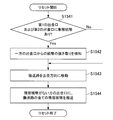
- FIG. 20 is a flowchart illustrating an example of the flow of another operation during the reset operation of the cash processing apparatus according to the second embodiment of the present invention.
- the control unit 1210 first determines whether or not there are stacked banknotes in the first withdrawal port 1102-1 and the second withdrawal port 1102-2 (step S1541). Presence / absence of stacked banknotes at the withdrawal port 1102 is detected by the detection unit 1220.
- step S1541 when there are stacked banknotes in both the first withdrawal port 1102-1 and the second withdrawal port 1102-2 (“Yes” in step S1541), the control unit 1210 removes from one withdrawal port 1102. It waits until the detection unit 1220 detects the withdrawal of the bill.
- control unit 1210 detects that all banknotes have been removed from the first withdrawal port 1102-1 or the second withdrawal port 1102-2, or if any one of the withdrawal ports 1102 If there is no stacked banknote (“No” in step S1541), the transport path 1103 is moved in the withdrawal direction (direction D2) (step S1543).
- control unit 1210 causes all banknotes remaining in the transport path 1103 to be transported to the withdrawal port 1102 on which the banknotes are not stacked (step S1544).
- the remaining banknotes are accumulated in the vacant withdrawal port 1102, and the operator can collect the remaining banknotes including the rejected banknotes from the withdrawal port 1102 without opening and closing the safe door.
- both the first withdrawal port 1102-1 and the second withdrawal port 1102-2 do not need to be emptied, so that the labor of the operator can be saved.
- the third embodiment of the present invention relates to a withdrawal operation of the cash processing apparatus 1010.
- the basic control of the dispensing operation is the same as in the second embodiment described above.
- the withdrawal transaction can be continued.
- the recognition unit 1104 recognizes that the banknote separated from the banknote cassette A is a reject banknote
- the control unit 1210 stops the separation of the banknote from the banknote cassette A and operates the transport path. After stopping, all banknotes remaining on the transport path 1103 are transported to the second withdrawal port 1102-2.
- the control unit 1210 resumes the separation of the banknote from the banknote cassette A, and transports the insufficient banknote in the withdrawal transaction to the first withdrawal port 1102-1. Then, the control unit 1210 notifies the occurrence of the failure after the conveyance of the insufficient banknotes and stops. Thereby, even when a reject banknote is generated, the withdrawal transaction can be continued.
- the shortage banknote is the amount obtained by subtracting the number of banknotes conveyed to the withdrawal port 1102-1 before the separation of the banknotes from the banknote cassette A is stopped from the designated number specified in the withdrawal transaction. The number of sheets.
- FIG. 21 and FIG. 22 are flowcharts showing an example of an operation flow when the cash processing apparatus 1010 according to the third embodiment of the present invention makes a withdrawal.
- the control unit 1210 determines whether or not the designated number has been separated (step S1601). If the designated number has been separated (“Yes” in step S1601), The gold movement ends.
- the control unit 1210 causes the withdrawal port 1102 to transport the banknote (Steps S1603 to S1605).
- the delivery port is not particularly limited. For example, when the first withdrawal port is not full (“No” in step S1603), the delivery port is transported to the first withdrawal port 1102-1 (step S1604). If the first withdrawal port is full (“Yes” in step S1603), the first withdrawal port is conveyed to the second withdrawal port 1102-2 (step S1605).
- step S1602 when the banknote separated from the banknote cassette A is recognized by the recognition section 1104 and the recognition result indicates that the banknote is a reject banknote (“Yes” in step S1602), the control unit 1210 has the banknote in the banknote cassette A. Is stopped (step S1606).
- control unit 1210 stops the conveyance path 1103 (step S1607).
- step S1608 when banknotes are accumulated in the second withdrawal port 1102-2 (“Yes” in step S1608), the control unit 1210 detects the withdrawal of the banknote from the second withdrawal port 1102-2. Wait until As shown in S1603 to S1605 above, when the first withdrawal port 1102-1 is Full, it is assumed that banknotes are withdrawn to the second withdrawal port 1102-2. By confirming that the withdrawal banknote has been extracted from the withdrawal opening 1102-2, the withdrawal banknote is prevented from being confused with the remaining banknote.
- step S1610 moves the transport path 1103 in the withdrawal direction (direction D2) (step S1610).
- control unit 1210 transports all banknotes remaining on the transport path 1103 to the second withdrawal port 1102-2 (step S1611).
- control unit 1210 determines whether or not the first withdrawal port 1102-1 is full (step S1612 shown in FIG. 22). As shown in S1603 to S1605 above, it is assumed that the withdrawal banknotes are normally accumulated in the first withdrawal port 1102-1.
- step S1612 If the first withdrawal port 1102-1 is full (“Yes” in step S1612), the control unit 1210 detects the withdrawal of the banknote from the first withdrawal port 1102-1 (S613), and then the banknote. Separation of banknotes from the cassette A is resumed, and the insufficient banknotes are conveyed to the first withdrawal port 1102-1 (step S1614). On the other hand, when the first withdrawal port 1102-1 is not full (“No” in step S1612), the control unit 1210 continues to convey the withdrawal banknote to the first withdrawal port 1102-1.
- the control unit 1210 places the cash processing apparatus 1010 in a failure state (step S1616) and ends the dispensing operation.
- the failure state of the cash processing apparatus 1010 is a state in which the operation is stopped until the operator performs a return operation (specifically, a reset instruction) after notifying the operator of the failure.
- the remaining banknote including the reject banknote is conveyed to the second withdrawal port 1102-2, and the insufficient banknote continues to the first withdrawal port 1102.
- the operator can continue the withdrawal transaction. Further, the reset operation can be performed after the withdrawal transaction is completed.
- FIG. 23 is a flowchart showing an example of an operation flow during a reset operation of the cash processing apparatus according to the third embodiment of the present invention.
- control unit 1210 determines whether or not there is a stacked banknote in the withdrawal port 1102 (step S1621).
- control unit 1210 ends the reset operation when detecting the withdrawal of all banknotes from all the withdrawal ports 1102 (step S1622). .
- control unit 1210 for controlling the entire operation of the cash processing apparatus 1010 may be configured by dedicated hardware, or the CPU built in the cash processing apparatus 1010 stores the program stored in the ROM in the RAM. It may be realized by expanding and executing. In addition to providing such a program, a storage medium storing such a program may also be provided.
- the cash processing apparatus 1010 by this embodiment is not limited to this.
- the present invention may be applied to a cash processing unit of an automatic transaction apparatus represented by an ATM of a customer operation type terminal that recycles (recycles) banknotes.
- Automatic transaction apparatuses are installed in various places such as banks, station premises, and convenience stores. The customer can perform transactions such as deposit, withdrawal and balance inquiry by performing various operations on the display screen displayed on the automatic transaction apparatus.
Landscapes
- Physics & Mathematics (AREA)
- General Physics & Mathematics (AREA)
- Financial Or Insurance-Related Operations Such As Payment And Settlement (AREA)
Abstract
【課題】異常な紙幣が発生した際、出金口から残留紙幣を排出することで、紙幣回収のために金庫扉を開ける作業を不要とすることが可能な技術を提供する。 【解決手段】紙幣が排出される出金口102と、紙幣を認識する認識部104と、紙幣を搬送する搬送路103と、搬送中の紙幣が認識部104によって異常であると認識された場合、当該紙幣が出金口102に搬送されるように搬送路103を制御する制御部210と、を備える、現金処理装置10が提供される。
Description
本発明は、現金処理装置に関するものである。
昨今、金融機関の営業店カウンタに設置される窓口用現金処理機に代表される現金処理装置は、紙幣や硬貨の入金取引、出金取引、整理計数などに利用される。オペレータは、この現金処理装置の操作部または現金処理装置に接続された受付端末から各種操作を行うことにより、入金、出金などの取引を行うことができる。かかる現金処理装置に関する技術としては様々な技術が開示されている。
例えば、下記特許文献1では、紙幣収納部から紙幣認識部に紙幣を搬送する経路と重複しないリジェクトルートを確保することが可能な紙幣処理装置が提案されている。また、下記特許文献2では、銀行窓口における入出金取引において、金額不一致等のトラブルが発生した場合であっても、その取引について検証を行うことができる窓口用紙幣入出金機が提案されている。
ここで、紙幣の収納動作時または出金時に異常紙幣が発生した場合には、その異常紙幣は入金庫に搬送されるのが一般的である。また、紙幣の収納動作時において、リサイクル不可紙幣を搬送する場合や、搬送先のリサイクルカセットに既に収納されている紙幣の枚数が上限値に達している場合などには、入金庫に設定された紙幣カセットに紙幣が搬送されるのが一般的である。
しかしながら、現金処理装置を扱うオペレータが、入金庫や入金庫に設定された紙幣カセットに収納された紙幣を回収するためには、現金処理装置の金庫扉を開けて現金処理装置の下部ユニットを引き出してから、入金庫や入金庫に設定された紙幣カセットを抜き取らなければならないのが一般的である。そのため、紙幣の回収のためにオペレータに煩雑な作業を強いる可能性がある。
また、例えば、金庫扉の鍵を銀行以外の会社が保持しているような国においては、銀行は、金庫扉を開けるための鍵を得るために、他の会社に依頼料を支払わなくてはならない場合もある。かかる場合には、現金処理装置を扱うオペレータに煩雑な手続きを強いる可能性がある。また、かかる場合には、現金処理装置を扱う銀行には、鍵を得るための依頼料が掛かってしまう。
そこで、本発明は、上記問題に鑑みてなされたものであり、本発明の目的とするところは、異常な紙幣(リジェクト紙幣)が発生した際、出金口から残留紙幣を排出することで、紙幣回収のために金庫扉を開ける作業を不要とすることが可能な技術を提供することにある。
上記問題を解決するために、本発明のある観点によれば、紙幣が排出される出金口と、紙幣を認識する認識部と、紙幣を搬送する搬送部と、搬送中の紙幣が前記認識部によって異常であると認識された場合、当該紙幣が前記出金口に搬送されるように前記搬送部を制御する制御部と、を備える、現金処理装置が提供される。
前記制御部は、前記搬送中の紙幣が前記認識部によって異常であると認識された場合、前記搬送部に残留している複数の紙幣を前記出金口に搬送させてよい。
前記出金口は、第1の出金口及び第2の出金口からなり、前記制御部は、前記搬送中の紙幣が前記認識部によって異常であると認識された場合、前記搬送部に残留している複数の紙幣を第1の出金口に搬送させ、前記第1の出金口に搬送された紙幣の枚数が上限値に達した場合、残りの紙幣を第2の出金口に搬送させてよい。
前記出金口は、第1の出金口及び第2の出金口からなり、前記制御部は、前記搬送中の紙幣が前記認識部によって異常であると認識された場合、前記搬送部に残留している複数の紙幣のうち、前記認識部によって正常であると認識された紙幣を第1の出金口に搬送させ、前記認識部によって異常であると認識された紙幣を第2の出金口に搬送させてよい。
前記現金処理装置は、紙幣を一時的に収納する一時保留部を備え、前記制御部は、前記一時保留部から分離された紙幣が前記認識部によって異常であると認識された場合、当該紙幣を前記出金口に搬送させてよい。
前記制御部は、前記一時保留部から分離された紙幣が前記認識部によって異常であると認識された場合、前記一時保留部からの紙幣の分離を停止させてよい。
前記現金処理装置は、紙幣を収納可能な紙幣カセットを備え、前記制御部は、前記一時保留部から分離された紙幣が前記認識部によって正常であると認識された場合、当該紙幣を前記紙幣カセットに搬送させてよい。
前記現金処理装置は、紙幣を収納する紙幣カセットを備え、前記制御部は、前記紙幣カセットから分離された紙幣が前記認識部によって異常であると認識された場合、当該紙幣を前記出金口に搬送させてよい。
前記制御部は、前記紙幣カセットから分離された紙幣が前記認識部によって異常であると認識された場合、前記紙幣カセットからの紙幣の分離を停止させてよい。
前記制御部は、前記紙幣カセットから分離された紙幣が前記認識部によって正常であると認識された場合、当該紙幣を前記出金口に搬送させてよい。
前記現金処理装置は、紙幣を一時的に収納する一時保留部を備え、前記制御部は、前記一時保留部から分離されて前記認識部によって認識された紙幣の搬送先がリサイクルカセットではない場合、当該紙幣を前記出金口に搬送させてよい。
また、前記現金処理装置は、紙幣の収納および繰り出しが可能な紙幣収納庫をさらに備え、前記制御部は、紙幣の搬送中にリジェクト紙幣が発生した際、紙幣の搬送動作を中止し、障害発生の通知を行った後、リセット処理により前記搬送部に残留している紙幣を前記出金口に搬送するよう制御してもよい。
また、前記制御部は、前記紙幣収納庫に紙幣を搬送する入金処理中に前記リジェクト紙幣が発生した際、前記リセット処理により前記搬送部に残留している全ての紙幣を前記出金口に搬送するよう制御してもよい。
また、前記制御部は、前記紙幣収納庫から紙幣を繰り出して前記出金口に搬送する出金処理中に前記リジェクト紙幣が発生した際、前記リセット処理により前記出金口の集積紙幣の検知結果に応じて、前記搬送部に残留している紙幣の前記出金口への搬送制御を行ってもよい。
また、前記出金口は、第1の出金口と第2の出金口からなり、前記制御部は、前記第1および第2のいずれの出金口にも集積紙幣が検知されなかった場合、前記第1の出金口に前記搬送部に残留している紙幣を搬送するよう制御してもよい。
また、前記出金口は、第1の出金口と第2の出金口からなり、前記制御部は、前記第1または第2のいずれか一方の出金口に集積紙幣が検知されなかった場合、集積紙幣が検知されなかった出金口に前記搬送部に残留している紙幣を搬送するよう制御してもよい。
また、前記リジェクト紙幣の発生は、前記紙幣認識部による認識結果に基づくものであってもよい。
また、前記現金処理装置は、紙幣が排出される複数の出金口と、紙幣の繰り出しが可能な紙幣収納庫をさらに備え、前記制御部は、前記紙幣収納庫から繰り出した紙幣を前記出金口に搬送中にリジェクト紙幣が発生した際、一方の出金口に前記リジェクト紙幣を搬送し、他方の出金口に不足紙幣を搬送して出金取引を継続するよう制御してもよい。
また、前記制御部は、不足紙幣の搬送が終了した後、障害発生の通知を行ってもよい。
また、前記制御部は、前記一方の出金口に前記リジェクト紙幣を搬送する際、前記一方の出金口に既に出金取引による紙幣が集積されている場合、前記一方の出金口の集積紙幣が抜き取られてから前記リジェクト紙幣の搬送を行ってもよい。
また、前記制御部は、前記他方の出金口に搬送された紙幣の枚数が上限値に達した場合、紙幣の搬送動作を中止し、前記他方の出金口の集積紙幣が抜き取られてから前記搬送動作を再開し、不足紙幣の搬送を継続してもよい。
以上説明したように本発明によれば、異常な紙幣(リジェクト紙幣)が発生した際、出金口から残留紙幣を排出することで、紙幣回収のために金庫扉を開ける作業を不要とすることが可能となる。
以下に添付図面を参照しながら、本発明の好適な実施の形態について詳細に説明する。なお、本明細書および図面において、実質的に同一の機能構成を有する構成要素については、同一の符号を付することにより重複説明を省略する。
また、本明細書および図面において、実質的に同一の機能構成を有する複数の構成要素を、同一の符号の後に異なるアルファベットまたは数字を付して区別する場合もある。ただし、実質的に同一の機能構成を有する複数の構成要素の各々を特に区別する必要がない場合、同一符号のみを付する。
<<1.第1の発明>>
<1-1.本発明の背景>
まず、一般的な現金処理装置90について説明する。図1は、一般的な現金処理装置90の要部構成図である。まず、図1を参照しながら、一般的な現金処理装置90の構成について説明する。例えば、現金処理装置90は、金融機関の受付窓口員などのオペレータによる操作に基づいて金銭の取引を実行する操作型端末であってよい。また、例えば、この現金処理装置90は、金融機関の営業店などに設置される。以下では、現金処理装置90が窓口用現金入出金機(TCR:Teller Cash Recycler)である場合を主に想定する。
<1-1.本発明の背景>
まず、一般的な現金処理装置90について説明する。図1は、一般的な現金処理装置90の要部構成図である。まず、図1を参照しながら、一般的な現金処理装置90の構成について説明する。例えば、現金処理装置90は、金融機関の受付窓口員などのオペレータによる操作に基づいて金銭の取引を実行する操作型端末であってよい。また、例えば、この現金処理装置90は、金融機関の営業店などに設置される。以下では、現金処理装置90が窓口用現金入出金機(TCR:Teller Cash Recycler)である場合を主に想定する。
図1に示すように、現金処理装置90は、入金口101、出金口102(第1の出金口102-1、第2の出金口102-2)、搬送路103、認識部104、一時保留部105、紙幣カセット106~110、入金庫(リジェクト庫)111およびブレード112、113を有する。なお、以下においては、説明の簡便さのため、スロットA~Eに装着される紙幣カセット106~110を紙幣カセットA~Eと記載し、スロットFに装着される入金庫111を入金庫Fと記載する場合もある。
入金口101は、オペレータによって紙幣が投入される投入口である。入金口101には、開口部を開閉するシャッタ(不図示)が設けられてよい。また、入金口101は、束で投入された紙幣を一枚ずつ分離して搬送路103に繰り出す分離機能を有していてよい。なお、入金口101は、搬送路103側に傾くことや、オペレータによる取り出し口側に傾くことが可能な可動式であってもよい。
出金口102は、オペレータが受け取る紙幣が排出される排出口である。出金口102には、開口部を開閉するシャッタ(不図示)が設けられてよい。また、出金口102は、排出する紙幣を集積する集積機能を有していてよい。なお、出金口102は、搬送路103側に傾くことや、オペレータによる取り出し口側に傾くことが可能な可動式であってもよい。図1に示すように、出金口102としては、第1の出金口102-1および第2の出金口102-2が存在してよい。現金処理装置90における第1の出金口102-1および第2の出金口102-2それぞれの位置は特に限定されない。
搬送路103は、紙幣を搬送する機能を有している。紙幣の搬送には、対向して当接する複数のローラの間に紙幣を挟んで送出する機構が用いられてよい。搬送路103は、駆動モータ(不図示)によって駆動され得る。駆動モータ(不図示)は、例えば、DCサーボモータまたはパルスモータによって構成されており、かかるモータが回転することにより搬送路103を駆動する。
駆動モータ(不図示)は、現金処理装置90の全体の動作を制御する制御部(不図示)の制御に従って、搬送路103が紙幣を目的の搬送先に搬送するように搬送路103を駆動する。搬送路103は、複数の搬送区間に分割され、複数の搬送区間がそれぞれの駆動モータによって駆動されてもよい。ブレード112、113は、搬送路103の分岐部分に配置されており、制御部(不図示)の制御に従って紙幣の搬送方向を制御する。例えば、ブレード112,113は、ロータリー式ソレノイドを直結させて回転する手法を用いて紙幣の搬送方向を制御してもよい。
認識部104は、1枚ずつ搬送される紙幣の認識を行う。認識部104は、双方向(方向D1および方向D2)に搬送される紙幣の認識を行うことができる。具体的には、認識部104は、搬送路103によって搬送された紙幣の金種、真偽、正損および走行状態などを鑑別し、搬送される紙幣に対して、正常判定または異常判定を行う。異常判定(リジェクト判定)は、真偽、正損(汚損、損壊、外形異常など)、走行異常(スキュー紙幣、重走など)といった要因に基づいて行われる。また、異常紙幣(以下、「リジェクト紙幣」とも言う。)は、出金紙幣として取り扱えない二千円札および五千円札を含んでもよいし、外国紙幣を含んでもよい。
一時保留部105は、紙幣の分離と収納の両方の機能を有する。例えば、一時保留部105は、入金時に入金口101から分離されて認識部104により正常と認識された紙幣を一時的に収納する。一時保留部105に収納された紙幣は、取引が成立した場合(例えば、入金した紙幣の口座計上が確定した場合)などに繰り出され、認識部104に搬送される。認識部104を経て紙幣カセットA~Dなどに搬送される。なお、一時保留部105の収納形式は、紙幣を順次重ねて集積する集積式であってもよいし、紙幣を順次巻いて収納するドラム式であってもよい。
紙幣カセットA~Dは、紙幣を金種毎に収納可能であり、紙幣の収納および分離の両方の機能を有する。紙幣カセットA~Dには、同一金種の紙幣を収納する紙幣カセットが存在してもよい。例えば、紙幣カセットA、Cが一万円札を収納可能であり、紙幣カセットB、Dが千円札を収納可能であってもよい。また、紙幣カセットA~Dは、現金処理装置90に対して着脱可能な構造になっていてよい。
紙幣カセットEは、紙幣を収納する収納機能および1枚ずつ繰り出す分離機能を有する。例えば、紙幣カセットEは、回収時に各紙幣カセットA~Dから分離された紙幣を収納することができる。また、紙幣カセットEは、補充時に収納している紙幣を繰り出し、紙幣カセットA~Dに紙幣を補充することができる。このように、紙幣カセットEは、複数の用途に利用され得る。また、紙幣カセットEは、現金処理装置90に対して着脱可能な構造になっていてよい。
入金庫Fは、紙幣を収納する収納機能を有する。例えば、入金庫Fは、認識部104によって異常であると認識された紙幣(リジェクト紙幣)を収納する機能を有している。また、入金庫Fは、リジェクト紙幣の他に、正常紙幣、外国紙幣、偽造券などといった、他の紙幣と様々な区別をされた紙幣を収納することが可能な多目的な紙幣カセット(入金庫)であってよい。また、入金庫Fは、現金処理装置90に対して着脱可能な構造になっていてよい。
以上、図1を参照しながら、一般的な現金処理装置90の基本的な機能について説明した。続いて、図2~図4を適宜参照しながら、一般的な現金処理装置90における取引ごとの紙幣の流れについて説明する。取引には、入金、収納、出金、補充、回収などが含まれ得る。
まず、一般的な現金処理装置90の入金時における紙幣の流れを説明する。入金時においては、オペレータによって入金口101に投入された紙幣が1枚ずつ方向D1に沿って搬送路103によって認識部104に搬送される。認識部104によってリジェクト紙幣であると認識された紙幣は、方向D1に沿って出金口102に搬送される。出金口102に搬送された紙幣は、入金口101に再度投入されることによって、認識部104によって再度認識され得る。
一方、認識部104によって正常であると認識された紙幣は、方向D2に沿って一時保留部105に搬送され、一時保留部105によって一時的に収納される。入金動作が終わると、現金処理装置90を制御する上位システム(不図示)によって入金金額が表示される。入金金額をオペレータが確認すると、上位システム(不図示)の収納開始指示に従って、現金処理装置90の動作が入金動作から収納動作に移行される。
図2は、一般的な現金処理装置90の収納動作時における動作の流れの例を示すフローチャートである。図2に示すように、収納動作時においては、一時保留部105に収納された紙幣が1枚ずつ方向D1に沿って搬送路103によって認識部104に搬送される。認識部104による認識結果がリジェクト紙幣である旨を示す場合は(ステップS101において「Yes」)、当該紙幣は方向D1に沿って搬送路103によって入金庫Fに搬送される(ステップS102)。
一方、認識部104による認識結果が正常である旨を示す場合は(ステップS101において「No」)、当該紙幣は方向D1に沿って搬送路103によって紙幣カセットA~Eのうち当該紙幣の金種と一致する金種が設定された紙幣カセットに搬送される(ステップS103)。
なお、入金完了後に、上位システム(不図示)の返却(キャンセル)指示に従って、現金処理装置90の動作が入金動作から返却動作に移行されてもよい。かかる場合、一時保留部105に収納された紙幣は、1枚ずつ方向D1に沿って搬送路103によって認識部104に搬送され、認識部104による認識結果に関わらず方向D1に沿って搬送路103によって出金口102に搬送されてよい。
続いて、一般的な現金処理装置90の出金時における紙幣の流れを説明する。図3は、一般的な現金処理装置90の出金時における動作の流れの例を示すフローチャートである。図3に示すように、出金時においては、紙幣カセットA~Eのうち指定金種が設定された紙幣カセットから指定枚数の紙幣が1枚ずつ分離されて方向D2に沿って搬送路103によって認識部104に搬送される。認識部104による認識結果がリジェクト紙幣である旨を示す場合は(ステップS201において「Yes」)、当該紙幣は方向D2に沿って搬送路103によって入金庫Fに搬送される(ステップS202)。
一方、認識部104による認識結果が正常である旨を示す場合は(ステップS201において「No」)、当該紙幣は方向D2に沿って搬送路103によって出金口102に搬送される(ステップS203)。
続いて、一般的な現金処理装置90の補充時における紙幣の流れを説明する。紙幣補充の手法としては、投入口補充、カセット交換補充およびカセット計数補充などが挙げられる。ここで、投入口補充の動作は、上記した入金動作および収納動作と同様になされ得る。また、カセット交換補充は、あらかじめ紙幣が収納された紙幣カセットを現金処理装置90にセットする手法であるが、かかる手法においては、認識部104により紙幣の計数処理が実行されないため、オペレータは、紙幣の金種および枚数をマニュアルで登録する必要がある。
カセット計数補充においては、紙幣カセットEから1枚ずつ分離された紙幣が方向D2に沿って搬送路103によって認識部104に搬送される。認識部104による認識結果がリジェクト紙幣である旨を示す場合は、当該紙幣は、方向D2に沿って入金庫Fに搬送される。一方、認識部104による認識結果が正常である旨を示す場合は、当該紙幣は、方向D2に沿って搬送路103によって一時保留部105に搬送される。
続いて、正常であると認識された紙幣は、一時保留部105から繰り出されて、方向D1に沿って搬送路103によって認識部104に搬送される。認識部104による認識結果がリジェクト紙幣である旨を示す場合は、当該紙幣は、方向D1に沿って入金庫Fに搬送される。一方、認識部104によって正常であると認識された紙幣は、方向D1に沿って搬送路103によって紙幣カセットA~Eのうち当該紙幣の金種と一致する金種が設定された紙幣カセットに搬送される。
続いて、一般的な現金処理装置90の回収時における紙幣の流れを説明する。紙幣回収の手法としては、出金口回収、カセット交換回収およびカセット計数回収などが挙げられる。ここで、出金口回収の動作は、上記した出金動作と同様になされ得る。また、カセット交換回収は、現金処理装置90から紙幣カセットを取り外して紙幣の回収を行う手法であるが、かかる手法においては、認識部104により紙幣の計数処理が実行されないため、オペレータは、取り外した紙幣カセットから紙幣を抜き取って紙幣の金種および枚数をマニュアルで数えるのが一般的な運用である。
カセット計数回収においては、紙幣カセットA~Dから1枚ずつ分離された紙幣が方向D2に沿って搬送路103によって認識部104に搬送される。認識部104によって異常であると認識されたリジェクト紙幣は、方向D2に沿って入金庫Fに搬送される。一方、認識部104によって正常であると認識された紙幣は、方向D2に沿って紙幣カセットEに搬送される。紙幣の計数が完了した後、オペレータは、紙幣カセットEを現金処理装置90から取り外して紙幣の回収を行うことができる。
図4は、一般的な現金処理装置90のカセット回収時におけるオペレータの作業の流れの例を示すフローチャートである。図4に示すように、紙幣カセットの回収がなされるに際しては、オペレータは、鍵を用いて金庫扉115を開ける(ステップS301)。続いて、オペレータは、現金処理装置90から下部ユニット114を取り外して(ステップS302)、現金処理装置90から紙幣カセットを取り外す。オペレータは、取り外した紙幣カセットから紙幣を抜き取り(ステップS303)、下部ユニット114を現金処理装置90に取り付け(ステップS304)、金庫扉を閉める(ステップS305)。
以上、図2~図4を適宜参照しながら、一般的な現金処理装置90における取引ごとの紙幣の流れについて説明した。ここで、上記したように、各取引時(例えば、収納動作時、出金時、補充時および回収時など)においては、紙幣の搬送中において認識部104によって異常であると認識されたリジェクト紙幣は、入金庫Fに搬送されてしまうのが一般的である。
また、紙幣の分離機能(紙幣を繰り出す機能)を有する出金庫、紙幣の集積する機能を有する出金庫の他に、紙幣の分離機能と紙幣の集積機能との双方を有する紙幣カセット(以下、「リサイクルカセット」とも言う。)が存在し得る。例えば、紙幣カセットA~Dがリサイクルカセットとなり得る。ここで、紙幣の収納動作時において、搬送先のリサイクルカセットに収納された紙幣の枚数が上限値に達している場合、入金庫に設定された紙幣カセットに紙幣が搬送されるのが一般的である。
なお、リサイクルカセットに対して補充する紙幣を繰り出し、リサイクルカセットから回収する紙幣を収納する紙幣カセット(装填回収庫)も存在し得る。例えば、紙幣カセットEが装填回収庫となり得る。
また、紙幣カセットに収納された後に出金対象とはされない紙幣(以下、「リサイクル不可紙幣」)が存在し得る。例えば、紙幣カセットA~Eの中に一致する金種が設定された紙幣カセットが存在しない金種の紙幣は、リサイクル不可紙幣として扱われ得る。リサイクル不可紙幣も、収納動作時において、入金庫に設定された紙幣カセットに紙幣が搬送されるのが一般的である。
しかし、現金処理装置90を扱うオペレータが、入金庫Fや入金庫に設定された紙幣カセットに収納された紙幣を回収するためには、現金処理装置90の金庫扉115を開けて現金処理装置90の下部ユニット114を引き出してから、入金庫Fや入金庫に設定された紙幣カセットを抜き取らなければならないのが一般的である。そのため、紙幣の回収のためにオペレータに煩雑な作業を強いる可能性がある。
また、例えば、金庫扉115の鍵を銀行以外の会社が保持しているような国においては、銀行は、金庫扉115を開けるための鍵を得るために、他の会社に依頼料を支払わなくてはならない場合もある。かかる場合には、現金処理装置90を扱うオペレータに煩雑な手続きを強いる可能性がある。また、かかる場合には、現金処理装置90を扱う銀行には、鍵を得るための依頼料が掛かってしまう。
そこで、本明細書においては、紙幣の回収のためにオペレータに煩雑な作業を強いる可能性を低減することが可能な技術を主に提案する。
なお、本明細書においては、紙幣カセットA~Eがループ状の搬送路103に対して放射状に接続されるように並べられ、出金時の搬送方向である方向D2に沿って紙幣カセットA~E、認識部104および入金庫Fが順に配置されている例を主に説明する。かかる例によれば、紙幣カセットA~Eから分離されて方向D2に沿って認識部104に搬送された紙幣が、認識部104によってリジェクト紙幣であると認識された場合、当該紙幣を入金庫Fに直接搬送することができるという利点が享受され得る。
<1-2.第1の発明の各実施形態>
続いて、本発明の実施形態に係る現金処理装置10について詳細に説明する。なお、本発明の実施形態に係る現金処理装置10の構成要素のうち、一般的な現金処理装置90と同様の構成要素については、同一の符号を付して説明は省略する。図5は、本発明の実施形態に係る現金処理装置10の要部構成図である。図5を参照しながら、本発明の実施形態に係る現金処理装置10の構成について説明する。
続いて、本発明の実施形態に係る現金処理装置10について詳細に説明する。なお、本発明の実施形態に係る現金処理装置10の構成要素のうち、一般的な現金処理装置90と同様の構成要素については、同一の符号を付して説明は省略する。図5は、本発明の実施形態に係る現金処理装置10の要部構成図である。図5を参照しながら、本発明の実施形態に係る現金処理装置10の構成について説明する。
一般的な現金処理装置90においては、入金庫Fが使用されるが、本発明の実施形態に係る現金処理装置10においては、入金庫Fは使用されなくてよい。したがって、図5に示すように、本発明の実施形態に係る現金処理装置10は、入金庫Fを有していなくてよい。ただし、入金庫Fが使用されなくてよいだけであるため、本発明の実施形態に係る現金処理装置10は、入金庫Fを備えてもよいことは言うまでもない。
図6は、本発明の実施形態に係る現金処理装置10の機能構成例を示すブロック図である。図6に示すように、本発明の実施形態に係る現金処理装置10は、制御部210と、検知部220と、記憶部230と、搬送部240とを備える。
制御部210は、現金処理装置10の動作全般を制御する。具体的には、制御部210は、上述した入金処理、出金処理、補充処理、回収処理などの基本処理を制御する。例えば、制御部210は、搬送部240による紙幣の搬送と、シャッタ(不図示)の開閉動作とを制御する。
検知部220は、例えば、光学センサなどを有し、様々な状態を検知する。例えば、検知部220は、入金口101や、出金口102(第1の出金口102-1、第2の出金口102-2)の紙幣の集積状態(集積枚数や、紙幣が抜き取られたか否か)を検知する。また、検知部220は、紙幣の搬送状態を検知し得る。検知部によって検知された結果は、制御部210に出力される。
記憶部230は、現金処理装置10が動作するためのプログラムや各種データなどを記憶する。また、記憶部230は、認識部104の鑑別結果を記憶し得る。搬送部240は、搬送路103によって構成され、制御部210の制御に従って紙幣を搬送する機能を有する。なお、制御部210および記憶部230の機能は、CPU(Central Processing Unit)、ROM(Read Only Memory)およびRAM(Random Access Memory)などから成るハードウェア構成により実現してもよい。
CPUは、演算機能および制御機能を有し、各種プログラムに従って現金処理装置10の動作全般を制御する。ROMは、CPUが使用するプログラムや演算パラメータなどを記憶する。RAMは、CPUの実行において使用するプログラムや、その実行において適宜変化するパラメータなどを一時記憶する。
本発明の実施形態において、制御部210は、搬送中の紙幣が認識部104によってリジェクト紙幣であると認識された場合、当該紙幣が出金口102に搬送されるように搬送路103を制御する。かかる構成によれば、搬送中の紙幣がリジェクト紙幣である場合には、当該紙幣が入金庫Fや入金庫に設定された紙幣カセットに収納されなくなる。したがって、現金処理装置10の金庫扉115を開けて現金処理装置10の下部ユニット114を引き出してから、入金庫Fや入金庫に設定された紙幣カセットを抜き取る作業が不要となる。そのため、紙幣の回収のためにオペレータに煩雑な作業を強いる可能性が低減される。
また、例えば、金庫扉の鍵を銀行以外の会社が保持しているような国においても、銀行は、金庫扉を開けるための鍵が不要となるため、他の会社に依頼料を支払わなくて済むようになる。したがって、現金処理装置10を扱うオペレータに煩雑な手続きを強いる可能性が低減される。以下、各実施形態において、現金処理装置10が有する機能のバリエーションを詳細に説明する。
(1-2-1.第1の実施形態)
まず、本発明の第1の実施形態を説明する。本発明の第1の実施形態は、現金処理装置10において入金が完了した後における紙幣の収納動作に関する。具体的には、入金が完了して紙幣が一時保留部105に収納されている状態において、収納動作が開始されると、一時保留部105から1枚ずつ紙幣が分離されて繰り出される。このとき、制御部210は、一時保留部105から分離された紙幣が認識部104によってリジェクト紙幣であると認識された場合、当該紙幣を出金口102に搬送させる。
まず、本発明の第1の実施形態を説明する。本発明の第1の実施形態は、現金処理装置10において入金が完了した後における紙幣の収納動作に関する。具体的には、入金が完了して紙幣が一時保留部105に収納されている状態において、収納動作が開始されると、一時保留部105から1枚ずつ紙幣が分離されて繰り出される。このとき、制御部210は、一時保留部105から分離された紙幣が認識部104によってリジェクト紙幣であると認識された場合、当該紙幣を出金口102に搬送させる。
ここで、制御部210は、一時保留部105から分離された紙幣が認識部104によってリジェクト紙幣であると認識された場合には、一時保留部105からの紙幣の分離を停止させるとよい。そうすれば、一時保留部105から搬送路103に紙幣が繰り出されてしまうのを防ぐことができる。また、搬送路103の搬送方向は特に限定されない。例えば、制御部210は、収納動作が開始されると、搬送方向が方向D1となるように搬送路103を制御してよい。一方、制御部210は、リジェクト紙幣が認識された場合には、搬送方向が方向D2となるように搬送路103を制御すればよい。
一方、制御部210は、一時保留部105から分離された紙幣が認識部104によって正常であると認識された場合、当該紙幣を紙幣カセットA~Dに搬送させてよい。このとき、例えば、制御部210は、紙幣カセットA~Dのうち、認識部104によって認識された紙幣の金種と同一の金種が設定されている紙幣カセットを、当該正常紙幣の搬送先として決定すればよい。
紙幣の搬送先の出金口102は特に限定されない。例えば、紙幣の搬送先の出金口102は、第1の出金口102-1であってもよいし、第2の出金口102-2であってもよい。また、認識部104によってリジェクト紙幣が認識された段階で搬送路103には、そのリジェクト紙幣を含んだ複数の紙幣が残留していることが想定される。したがって、制御部210は、搬送中の紙幣が認識部104によってリジェクト紙幣であると認識された場合、搬送路103に残留している複数の紙幣を出金口102に搬送させてよい。
制御部210は、搬送中の紙幣が認識部104によってリジェクト紙幣であると認識された場合、搬送路103に残留している複数の紙幣の搬送先の出金口102を状況に応じて選択してもよい。例えば、制御部210は、搬送中の紙幣が認識部104によってリジェクト紙幣であると認識された場合、搬送路103に残留している複数の紙幣のうち、認識部104によって正常であると認識された紙幣を第1の出金口102-1に搬送させ、認識部104によってリジェクト紙幣であると認識された紙幣を第2の出金口102-2に搬送させてよい。
かかる構成によれば、第1の出金口102-1には正常紙幣が集積され、第2の出金口102-2にはリジェクト紙幣が集積されるため、オペレータは、出金口102から抜き取った複数の紙幣を正常紙幣とリジェクト紙幣とに仕分ける作業を行わなくて済むようになる。この例について、図7を参照しながら説明する。図7は、本発明の第1の実施形態に係る現金処理装置10の収納動作時における動作の流れの例を示すフローチャートである。
図7に示すように、収納動作時において、制御部210は、一時保留部105から分離された紙幣が認識部104によって認識され、認識結果が正常紙幣である旨を示す場合には(ステップS401において「No」)、搬送先の紙幣カセットに当該紙幣を搬送させ(ステップS402)、収納動作を終了する。一方、制御部210は、一時保留部105から分離された紙幣が認識部104によって認識され、認識結果がリジェクト紙幣である旨を示す場合には(ステップS401において「Yes」)、一時保留部105における紙幣の分離を停止させる(ステップS403)。
また、制御部210は、搬送路103を停止させる(ステップS404)。一時保留部105からの紙幣の分離が停止されているため、搬送路103を停止させることによって紙幣の破れを防止することができる。なお、制御部210は、搬送路103の全体を停止させてもよいし、搬送路103の一部を停止させてもよい。例えば、制御部210は、搬送路103の一部を停止させる場合には、一時保留部105と一時保留部105への枝分かれ部分に存在するブレード113との間の搬送路103を停止させてもよい。
続いて、制御部210は、搬送路103を収納方向(方向D1)とは逆方向(方向D2)に移動させる(ステップS405)。続いて、制御部210は、搬送路103に残留している複数の紙幣がリジェクト紙幣か否かを順に判定し(ステップS406)、当該紙幣が正常紙幣である場合(ステップS406において「No」)、当該紙幣を第1の出金口102-1に搬送させ(ステップS407)、当該紙幣がリジェクト紙幣である場合(ステップS406において「Yes」)、当該紙幣を第2の出金口102-2に搬送させてよい(ステップS408)。
続いて、制御部210は、現金処理装置10を障害状態にし(ステップS409)、収納動作を終了してよい。現金処理装置10の障害状態は特に限定されないが、現金処理装置10に対してオペレータが復帰の操作を行うまで、動作が停止されている状態であってよい。
なお、搬送路103に残留している複数の紙幣の搬送先の出金口102の選択手法はかかる例に限定されない。例えば、制御部210は、搬送中の紙幣が認識部104によってリジェクト紙幣であると認識された場合、搬送路103に残留している複数の紙幣を第1の出金口102-1に搬送させ、第1の出金口102-1に搬送された紙幣の枚数が上限値に達した場合、残りの紙幣を第2の出金口102-2に搬送させてもよい。かかる上限値は特に限定されないため、第1の出金口102-1のサイズに応じて適宜に設定されてよい。
(1-2-2.第2の実施形態)
まず、本発明の第2の実施形態を説明する。本発明の第2の実施形態は、現金処理装置10において出金動作に関する。具体的には、複数の紙幣が紙幣カセットAに収納されている状態において、出金動作が開始されると、紙幣カセットAから1枚ずつ紙幣が分離されて繰り出される。ここでは、紙幣カセットAを用いて説明するが、紙幣カセットAの代わりに紙幣カセットB~Eが用いられてもよい。制御部210は、紙幣カセットAから分離された紙幣が認識部104によってリジェクト紙幣であると認識された場合、当該紙幣を出金口102に搬送させる。
まず、本発明の第2の実施形態を説明する。本発明の第2の実施形態は、現金処理装置10において出金動作に関する。具体的には、複数の紙幣が紙幣カセットAに収納されている状態において、出金動作が開始されると、紙幣カセットAから1枚ずつ紙幣が分離されて繰り出される。ここでは、紙幣カセットAを用いて説明するが、紙幣カセットAの代わりに紙幣カセットB~Eが用いられてもよい。制御部210は、紙幣カセットAから分離された紙幣が認識部104によってリジェクト紙幣であると認識された場合、当該紙幣を出金口102に搬送させる。
ここで、制御部210は、紙幣カセットAから分離された紙幣が認識部104によってリジェクト紙幣であると認識された場合には、一時保留部105からの紙幣の分離を停止させるとよい。そうすれば、紙幣カセットAから搬送路103に紙幣が繰り出されてしまうのを防ぐことができる。また、搬送路103の搬送方向は特に限定されない。例えば、制御部210は、出金動作が開始されると、搬送方向が方向D2となるように搬送路103を制御してよい。一方、制御部210は、リジェクト紙幣が認識された場合には、搬送方向が方向D2のままとなるように搬送路103を制御すればよい。
一方、制御部210は、紙幣カセットAから分離された紙幣が認識部104によって正常であると認識された場合、当該紙幣を出金口102に搬送させてよい。紙幣の搬送先の出金口102は特に限定されない。例えば、紙幣の搬送先の出金口102は、第1の出金口102-1であってもよいし、第2の出金口102-2であってもよい。また、認識部104によってリジェクト紙幣が認識された段階で搬送路103には、そのリジェクト紙幣を含んだ複数の紙幣が残留していることが想定される。したがって、制御部210は、搬送中の紙幣が認識部104によってリジェクト紙幣であると認識された場合、搬送路103に残留している複数の紙幣を出金口102に搬送させてよい。
制御部210は、搬送中の紙幣が認識部104によってリジェクト紙幣であると認識された場合、搬送路103に残留している複数の紙幣の搬送先の出金口102を状況に応じて選択してもよい。例えば、制御部210は、搬送中の紙幣が認識部104によってリジェクト紙幣であると認識された場合、搬送路103に残留している複数の紙幣のうち、認識部104によって正常であると認識された紙幣を第1の出金口102-1に搬送させ、認識部104によってリジェクト紙幣であると認識された紙幣を第2の出金口102-2に搬送させてよい。
かかる構成によれば、第1の出金口102-1には正常紙幣が集積され、第2の出金口102-2にはリジェクト紙幣が集積されるため、オペレータは、出金口102から抜き取った複数の紙幣を正常紙幣とリジェクト紙幣とに仕分ける作業を行わなくて済むようになる。この例について、図8を参照しながら説明する。図8は、本発明の第2の実施形態に係る現金処理装置10の出金時における動作の流れの例を示すフローチャートである。
図8に示すように、出金時において、制御部210は、紙幣カセットAから分離された紙幣が認識部104によって認識され、認識結果が正常紙幣である旨を示す場合には(ステップS501において「No」)、出金口102に当該紙幣を搬送させ(ステップS502)、収納動作を終了する。一方、制御部210は、紙幣カセットAから分離された紙幣が認識部104によって認識され、認識結果がリジェクト紙幣である旨を示す場合には(ステップS501において「Yes」)、紙幣カセットAにおける紙幣の分離を停止させる(ステップS503)。
また、制御部210は、搬送路103を停止させる(ステップS504)。紙幣カセットAからの紙幣の分離が停止されているため、搬送路103を停止させることによって紙幣の破れを防止することができる。なお、制御部210は、搬送路103の全体を停止させてもよいし、搬送路103の一部を停止させてもよい。例えば、制御部210は、搬送路103の一部を停止させる場合には、紙幣カセットAと紙幣カセットAへの枝分かれ部分に存在するブレード112との間の搬送路103を停止させてもよい。
続いて、制御部210は、搬送路103を出金方向(方向D2)に移動させる(ステップS505)。続いて、制御部210は、搬送路103に残留している複数の紙幣がリジェクト紙幣か否かを順に判定し(ステップS506)、当該紙幣が正常紙幣である場合(ステップS506において「No」)、当該紙幣を第1の出金口102-1に搬送させ(ステップS507)、当該紙幣がリジェクト紙幣である場合(ステップS506において「Yes」)、当該紙幣を第2の出金口102-2に搬送させてよい(ステップS508)。
続いて、制御部210は、現金処理装置10を障害状態にし(ステップS509)、出金動作を終了してよい。なお、上記したように、現金処理装置10の障害状態は特に限定されない。
なお、搬送路103に残留している複数の紙幣の搬送先の出金口102の選択手法はかかる例に限定されない。例えば、制御部210は、搬送中の紙幣が認識部104によってリジェクト紙幣であると認識された場合、搬送路103に残留している複数の紙幣を第1の出金口102-1に搬送させ、第1の出金口102-1に搬送された紙幣の枚数が上限値に達した場合、残りの紙幣を第2の出金口102-2に搬送させてもよい。かかる上限値は特に限定されないため、第1の出金口102-1のサイズに応じて適宜に設定されてよい。
(1-2-3.第3の実施形態)
まず、本発明の第3の実施形態を説明する。本発明の第3の実施形態は、現金処理装置10において入金が完了した後における紙幣の収納動作に関する。具体的には、入金が完了して紙幣が一時保留部105に収納されている状態において、収納動作が開始されると、一時保留部105から1枚ずつ紙幣が分離されて繰り出される。このとき、制御部210は、一時保留部105から分離されて認識部104によって認識された紙幣の搬送先がリサイクルカセット以外の場合、当該紙幣を出金口102に搬送させる。
まず、本発明の第3の実施形態を説明する。本発明の第3の実施形態は、現金処理装置10において入金が完了した後における紙幣の収納動作に関する。具体的には、入金が完了して紙幣が一時保留部105に収納されている状態において、収納動作が開始されると、一時保留部105から1枚ずつ紙幣が分離されて繰り出される。このとき、制御部210は、一時保留部105から分離されて認識部104によって認識された紙幣の搬送先がリサイクルカセット以外の場合、当該紙幣を出金口102に搬送させる。
かかる構成によれば、入金庫に設定された紙幣カセットに紙幣を搬送させなくて済むため、リサイクルカセットとして利用可能な紙幣カセットを増加させることが可能である。これによって、現金処理装置10において取り扱うことができる券種を増加させることが可能となる。
一例として、紙幣カセットA~Eの券種を順に、(金種100元、発行2005年)、(金種50元、発行2005年)、(金種100元、発行1999年)、(金種50元、発行1999年)および(金種20元、発行2005年)としてもよい。また、他の例として、紙幣カセットA~Eの券種を順に、(金種100元)、(金種50元)、(金種一万円)、(金種五千円)および(金種千円)としてもよい。
一例として、制御部210は、一時保留部105から分離されて認識部104によって認識された紙幣がリサイクル不可紙幣である場合、当該紙幣を出金口102に搬送させる。より具体的には、制御部210は、一時保留部105から分離されて認識部104によって認識された紙幣の金種がリサイクルカセットに設定された金種と一致しない場合、当該紙幣を出金口102に搬送させてよい。
他の一例として、制御部210は、一時保留部105から分離されて認識部104によって認識された紙幣の搬送先がリサイクルカセットであるが、リサイクルカセットに収納された紙幣の枚数が上限値に達している場合、当該紙幣を出金口102に搬送させる。より具体的には、一時保留部105から分離されて認識部104によって認識された紙幣の金種がリサイクルカセットに設定された金種と一致する場合、かつ、リサイクルカセットに収納された紙幣の枚数が上限値に達している場合、当該紙幣を出金口102に搬送させてよい。
ここで、制御部210は、一時保留部105から分離された紙幣の搬送先がリサイクルカセットではない場合には、一時保留部105からの紙幣の分離を停止させるとよい。そうすれば、一時保留部105から搬送路103に紙幣が繰り出されてしまうのを防ぐことができる。また、搬送路103の搬送方向は特に限定されない。例えば、制御部210は、収納動作が開始されると、搬送方向が方向D1となるように搬送路103を制御してよい。一方、制御部210は、紙幣の搬送先がリサイクルカセットではない場合には、搬送方向が方向D2となるように搬送路103を制御すればよい。
一方、制御部210は、一時保留部105から分離された紙幣の搬送先がリサイクルカセットであると判定した場合、当該紙幣をリサイクルカセットに搬送させてよい。このとき、例えば、制御部210は、紙幣カセットA~Dのうち、認識部104によって認識された紙幣の金種と同一の金種が設定されている紙幣カセットを、当該紙幣の搬送先として決定し、決定した搬送先がリサイクルカセットであるか否かを判定すればよい。
紙幣の搬送先の出金口102は特に限定されない。例えば、紙幣の搬送先の出金口102は、第1の出金口102-1であってもよいし、第2の出金口102-2であってもよい。また、一時保留部105から分離された紙幣の搬送先がリサイクルカセットであると判定された段階で搬送路103には、そのリジェクト紙幣を含んだ複数の紙幣が残留していることが想定される。したがって、制御部210は、搬送中の紙幣の搬送先がリサイクルカセットであると判定した場合、搬送路103に残留している複数の紙幣を出金口102に搬送させてよい。
制御部210は、搬送中の紙幣の搬送先がリサイクルカセットであると判定した場合、搬送路103に残留している複数の紙幣の搬送先の出金口102を状況に応じて選択してもよい。例えば、制御部210は、搬送中の紙幣の搬送先がリサイクルカセットであると判定した場合、搬送路103に残留している複数の紙幣のうち、認識部104によって正常であると認識された紙幣を第1の出金口102-1に搬送させ、認識部104によってリジェクト紙幣であると認識された紙幣を第2の出金口102-2に搬送させてよい。
かかる構成によれば、第1の出金口102-1には正常紙幣が集積され、第2の出金口102-2にはリジェクト紙幣が集積されるため、オペレータは、出金口102から抜き取った複数の紙幣を正常紙幣とリジェクト紙幣とに仕分ける作業を行わなくて済むようになる。この例について、図9を参照しながら説明する。図9は、本発明の第3の実施形態に係る現金処理装置10の収納動作時における動作の流れの例を示すフローチャートである。
図9に示すように、収納動作時において、制御部210は、一時保留部105から分離された紙幣が認識部104によって認識され、認識結果が正常紙幣である旨を示す場合には(ステップS601において「No」)、ステップS611に進む。一方、制御部210は、一時保留部105から分離された紙幣が認識部104によって認識され、認識結果がリジェクト紙幣である旨を示す場合には(ステップS601において「Yes」)、ステップS603に進む。図9に示したステップS603~S608は、図7に示したステップS403~ステップS408と同様に実行され得るため、説明を省略する。
続いて、制御部210は、搬送中の紙幣の搬送先がリサイクルカセットであるか否かを判定する(ステップS611)。制御部210は、搬送中の紙幣の搬送先がリサイクルカセットである場合には(ステップS611において「Yes」)、リサイクルカセットに紙幣を搬送させ(ステップS612)、収納動作を終了する。
一方、制御部210は、搬送中の紙幣の搬送先がリサイクルカセットではない場合には(ステップS611において「No」)、一時保留部105における紙幣の分離を停止させる(ステップS613)。また、制御部210は、搬送路103を停止させる(ステップS614)。一時保留部105からの紙幣の分離が停止されているため、搬送路103を停止させることによって紙幣の破れを防止することができる。なお、制御部210は、搬送路103の全体を停止させてもよいし、搬送路103の一部を停止させてもよい。例えば、制御部210は、搬送路103の一部を停止させる場合には、一時保留部105と一時保留部105への枝分かれ部分に存在するブレード113との間の搬送路103を停止させてもよい。
続いて、制御部210は、搬送路103を収納方向(方向D1)とは逆方向(方向D2)に移動させる(ステップS615)。続いて、制御部210は、搬送路103に残留している複数の紙幣がリジェクト紙幣か否かを順に判定し(ステップS616)、当該紙幣が正常紙幣である場合(ステップS616において「No」)、当該紙幣を第1の出金口102-1に搬送させ(ステップS617)、当該紙幣がリジェクト紙幣である場合(ステップS616において「Yes」)、当該紙幣を第2の出金口102-2に搬送させてよい(ステップS618)。
続いて、制御部210は、現金処理装置10を障害状態にし(ステップS619)、収納動作を終了してよい。なお、上記したように、現金処理装置10の障害状態は特に限定されない。
なお、搬送路103に残留している複数の紙幣の搬送先の出金口102の選択手法はかかる例に限定されない。例えば、制御部210は、搬送中の紙幣の搬送先がリサイクルカセットであると判定した場合、搬送路103に残留している複数の紙幣を第1の出金口102-1に搬送させ、第1の出金口102-1に搬送された紙幣の枚数が上限値に達した場合、残りの紙幣を第2の出金口102-2に搬送させてもよい。かかる上限値は特に限定されないため、第1の出金口102-1のサイズに応じて適宜に設定されてよい。
<1-3.第1の発明のまとめ>
以上、添付図面を参照しながら本発明の好適な実施形態について詳細に説明したが、本発明はかかる例に限定されない。本発明の属する技術の分野における通常の知識を有する者であれば、特許請求の範囲に記載された技術的思想の範疇内において、各種の変更例または修正例に想到し得ることは明らかであり、これらについても、当然に本発明の技術的範囲に属するものと了解される。
以上、添付図面を参照しながら本発明の好適な実施形態について詳細に説明したが、本発明はかかる例に限定されない。本発明の属する技術の分野における通常の知識を有する者であれば、特許請求の範囲に記載された技術的思想の範疇内において、各種の変更例または修正例に想到し得ることは明らかであり、これらについても、当然に本発明の技術的範囲に属するものと了解される。
例えば、現金処理装置10の動作全体を制御するための制御部210は、専用のハードウェアによって構成されてもよいし、現金処理装置10に内蔵されたCPUがROMに記憶されたプログラムをRAMに展開して実行することにより実現されてもよい。かかるプログラムが提供され得る他、かかるプログラムを記憶させた記憶媒体も提供され得る。
また、上述した実施形態は、本実施形態による現金処理装置10を、職員操作型端末に適用して説明したが、本実施形態による現金処理装置10は、これに限定されない。例えば、顧客操作型端末であって、紙幣を還流させる(リサイクルさせる)タイプのATMに代表される自動取引装置の現金処理部に適用してもよい。自動取引装置は、銀行、駅構内およびコンビニエンスストアなど、多様な場所に設置されている。顧客は、この自動取引装置に表示される表示画面において各種操作を行うことにより、入金、出金および残高照会などの取引を行うことができる。
<<2.第2の発明>>
本発明は、さらに多様な形態で実施され得る。また、以下に説明する第2の発明による現金処理装置(1010)は、
A.紙幣が排出される出金口(1102)と、
紙幣が正常であるか否かを認識する認識部(1104)と、
B.紙幣の収納および繰り出しが可能な紙幣収納庫(1106~1110)と、
C.紙幣を搬送する搬送部(1103)と、
D.紙幣の搬送中にリジェクト紙幣が発生した際、紙幣の搬送動作を中止し、障害発生の通知を行った後、リセット処理により前記搬送路に残留している紙幣を前記出金口に搬送するよう制御する制御部(CPU1040)と、
を有する。
本発明は、さらに多様な形態で実施され得る。また、以下に説明する第2の発明による現金処理装置(1010)は、
A.紙幣が排出される出金口(1102)と、
紙幣が正常であるか否かを認識する認識部(1104)と、
B.紙幣の収納および繰り出しが可能な紙幣収納庫(1106~1110)と、
C.紙幣を搬送する搬送部(1103)と、
D.紙幣の搬送中にリジェクト紙幣が発生した際、紙幣の搬送動作を中止し、障害発生の通知を行った後、リセット処理により前記搬送路に残留している紙幣を前記出金口に搬送するよう制御する制御部(CPU1040)と、
を有する。
<2-1.本発明の背景>
まず、一般的な現金処理装置1090の構成について図10を参照して説明する。図10は、一般的な現金処理装置1090の要部構成図である。例えば、現金処理装置1090は、金融機関の受付窓口員などのオペレータによる操作に基づいて金銭の取引を実行する操作型端末であってよい。また、例えば、この現金処理装置1090は、金融機関の営業店などに設置される。以下では、現金処理装置1090が窓口用現金入出金機(TCR:Teller Cash Recycler)である場合を主に想定する。
まず、一般的な現金処理装置1090の構成について図10を参照して説明する。図10は、一般的な現金処理装置1090の要部構成図である。例えば、現金処理装置1090は、金融機関の受付窓口員などのオペレータによる操作に基づいて金銭の取引を実行する操作型端末であってよい。また、例えば、この現金処理装置1090は、金融機関の営業店などに設置される。以下では、現金処理装置1090が窓口用現金入出金機(TCR:Teller Cash Recycler)である場合を主に想定する。
図10に示すように、現金処理装置1090は、入金口1101、出金口1102(第1の出金口1102-1、第2の出金口1102-2)、搬送路1103、認識部1104、一時保留部1105、紙幣カセット1106~1110、入金庫(リジェクト庫)1111およびブレード1112、1113を有する。なお、以下においては、説明の簡便さのため、スロットA~Eに装着される紙幣カセット1106~1110を紙幣カセットA~Eと記載し、スロットFに装着される入金庫1111を入金庫Fと記載する場合もある。
入金口1101は、オペレータによって紙幣が投入される投入口である。入金口1101には、開口部を開閉するシャッタ(不図示)が設けられてよい。また、入金口1101は、束で投入された紙幣を一枚ずつ分離して搬送路1103に繰り出す分離機能を有していてよい。なお、入金口1101は、搬送路1103側に傾くことや、オペレータによる取り出し口側に傾くことが可能な可動式であってもよい。
出金口1102は、オペレータが受け取る紙幣が排出される排出口である。出金口1102には、開口部を開閉するシャッタ(不図示)が設けられてよい。また、出金口1102は、排出する紙幣を集積する集積機能を有していてよい。なお、出金口1102は、搬送路1103側に傾くことや、オペレータによる取り出し口側に傾くことが可能な可動式であってもよい。図10に示すように、出金口1102としては、第1の出金口1102-1および第2の出金口1102-2が存在してよい。現金処理装置1090における第1の出金口1102-1および第2の出金口1102-2それぞれの位置は特に限定されない。
搬送路1103は、紙幣を搬送する機能を有している。紙幣の搬送には、対向して当接する複数のローラの間に紙幣を挟んで送出する機構が用いられてよい。搬送路1103は、駆動モータ(不図示)によって駆動され得る。駆動モータ(不図示)は、例えば、DCサーボモータまたはパルスモータによって構成されており、かかるモータが回転することにより搬送路1103を駆動する。
駆動モータ(不図示)は、現金処理装置1090の全体の動作を制御する制御部(不図示)の制御に従って、搬送路1103が紙幣を目的の搬送先に搬送するように搬送路1103を駆動する。搬送路1103は、複数の搬送区間に分割され、複数の搬送区間がそれぞれの駆動モータによって駆動されてもよい。ブレード1112、1113は、搬送路1103の分岐部分に配置されており、制御部(不図示)の制御に従って紙幣の搬送方向を制御する。例えば、ブレード1112、1113は、ロータリー式ソレノイドを直結させて回転する手法を用いて紙幣の搬送方向を制御してもよい。
認識部1104は、1枚ずつ搬送される紙幣の認識を行う。認識部1104は、双方向(方向D1および方向D2)に搬送される紙幣の認識を行うことができる。具体的には、認識部1104は、搬送路1103によって搬送された紙幣の金種、真偽、正損および走行状態などを鑑別し、搬送される紙幣に対して、正常判定または異常判定を行う。異常判定(リジェクト判定)は、真偽、正損(汚損、損壊、外形異常など)、走行異常(スキュー紙幣、重走など)といった要因に基づいて行われる。また、異常紙幣(以下、「リジェクト紙幣」とも言う。)は、出金紙幣として取り扱えない二千円札および五千円札を含んでもよいし、外国紙幣を含んでもよい。
一時保留部1105は、紙幣の分離と収納の両方の機能を有する。例えば、一時保留部1105は、入金時に入金口1101から分離されて認識部1104により正常と認識された紙幣を一時的に収納する。一時保留部1105に収納された紙幣は、取引が成立した場合(例えば、入金した紙幣の口座計上が確定した場合)などに繰り出され、認識部1104に搬送される。認識部1104を経て紙幣カセットA~Dなどに搬送される。なお、一時保留部1105の収納形式は、紙幣を順次重ねて集積する集積式であってもよいし、紙幣を順次巻いて収納するドラム式であってもよい。
紙幣カセットA~Dは、紙幣を金種毎に収納可能であり、紙幣の収納および分離の両方の機能を有する。紙幣カセットA~Dには、同一金種の紙幣を収納する紙幣カセットが存在してもよい。例えば、紙幣カセットA、Cが一万円札を収納可能であり、紙幣カセットB、Dが千円札を収納可能であってもよい。また、紙幣カセットA~Dは、現金処理装置1090に対して着脱可能な構造になっていてよい。
紙幣カセットEは、紙幣を収納する収納機能および1枚ずつ繰り出す分離機能を有する。例えば、紙幣カセットEは、回収時に各紙幣カセットA~Dから分離された紙幣を収納することができる。また、紙幣カセットEは、補充時に収納している紙幣を繰り出し、紙幣カセットA~Dに紙幣を補充することができる。このように、紙幣カセットEは、複数の用途に利用され得る。また、紙幣カセットEは、現金処理装置1090に対して着脱可能な構造になっていてよい。
入金庫Fは、紙幣を収納する収納機能を有する。例えば、入金庫Fは、認識部1104によって異常であると認識された紙幣(リジェクト紙幣)を収納する機能を有している。また、入金庫Fは、リジェクト紙幣の他に、正常紙幣、外国紙幣、偽造券などといった、他の紙幣と様々な区別をされた紙幣を収納することが可能な多目的な紙幣カセット(入金庫)であってよい。また、入金庫Fは、現金処理装置1090に対して着脱可能な構造になっていてよい。
以上、図10を参照しながら、一般的な現金処理装置1090の基本的な機能について説明した。続いて、図11~図13を適宜参照しながら、一般的な現金処理装置1090における取引ごとの紙幣の流れについて説明する。取引には、入金、収納、出金、補充、回収などが含まれ得る。
まず、一般的な現金処理装置1090の入金時における紙幣の流れを説明する。入金時においては、オペレータによって入金口1101に投入された紙幣が1枚ずつ方向D1に沿って搬送路1103によって認識部1104に搬送される。認識部1104によってリジェクト紙幣であると認識された紙幣は、方向D1に沿って出金口1102に搬送される。出金口1102に搬送された紙幣は、入金口1101に再度投入されることによって、認識部1104によって再度認識され得る。
一方、認識部1104によって正常であると認識された紙幣は、方向D1に沿って一時保留部1105に搬送され、一時保留部1105によって一時的に収納される。入金動作が終わると、現金処理装置1090を制御する上位システム(不図示)によって入金金額が表示される。入金金額をオペレータが確認すると、上位システム(不図示)の収納開始指示に従って、現金処理装置1090の動作が入金動作から収納動作に移行される。
図11は、一般的な現金処理装置1090の収納動作時における動作の流れの例を示すフローチャートである。図11に示すように、収納動作時においては、一時保留部1105に収納された紙幣が1枚ずつ方向D1に沿って搬送路1103によって認識部1104に搬送される。認識部1104による認識結果がリジェクト紙幣である旨を示す場合は(ステップS11101において「Yes」)、当該紙幣は方向D1に沿って搬送路1103によって入金庫Fに搬送される(ステップS11102)。
一方、認識部1104による認識結果が正常である旨を示す場合は(ステップS11101において「No」)、当該紙幣は方向D1に沿って搬送路1103によって紙幣カセットA~Eのうち当該紙幣の金種と一致する金種が設定された紙幣カセットに搬送される(ステップS11103)。
なお、入金完了後に、上位システム(不図示)の返却(キャンセル)指示に従って、現金処理装置1090の動作が入金動作から返却動作に移行されてもよい。かかる場合、一時保留部1105に収納された紙幣は、1枚ずつ方向D1に沿って搬送路1103によって認識部1104に搬送され、認識部1104による認識結果に関わらず方向D1に沿って搬送路1103によって出金口1102に搬送されてよい。
続いて、一般的な現金処理装置1090の出金時における紙幣の流れを説明する。図12は、一般的な現金処理装置1090の出金時における動作の流れの例を示すフローチャートである。図12に示すように、出金時においては、紙幣カセットA~Eのうち指定金種が設定された紙幣カセットから指定枚数の紙幣が1枚ずつ分離されて方向D2に沿って搬送路1103によって認識部1104に搬送される。認識部1104による認識結果がリジェクト紙幣である旨を示す場合は(ステップS1201において「Yes」)、当該紙幣は方向D2に沿って搬送路1103によって入金庫Fに搬送される(ステップS1202)。
一方、認識部1104による認識結果が正常である旨を示す場合は(ステップS1201において「No」)、当該紙幣は方向D2に沿って搬送路1103によって出金口1102に搬送される(ステップS1203)。
続いて、一般的な現金処理装置1090の補充時における紙幣の流れを説明する。紙幣補充の手法としては、投入口補充、カセット交換補充およびカセット計数補充などが挙げられる。ここで、投入口補充の動作は、上記した入金動作および収納動作と同様になされ得る。また、カセット交換補充は、あらかじめ紙幣が収納された紙幣カセットを現金処理装置1090にセットする手法であるが、かかる手法においては、認識部1104により紙幣の計数処理が実行されないため、オペレータは、紙幣の金種および枚数をマニュアルで登録する必要がある。
カセット計数補充においては、紙幣カセットEから1枚ずつ分離された紙幣が方向D2に沿って搬送路1103によって認識部1104に搬送される。認識部1104による認識結果がリジェクト紙幣である旨を示す場合は、当該紙幣は、方向D2に沿って入金庫Fに搬送される。一方、認識部1104による認識結果が正常である旨を示す場合は、当該紙幣は、方向D2に沿って搬送路1103によって一時保留部1105に搬送される。
続いて、正常であると認識された紙幣は、一時保留部1105から繰り出されて、方向D1に沿って搬送路1103によって認識部1104に搬送される。認識部1104による認識結果がリジェクト紙幣である旨を示す場合は、当該紙幣は、方向D1に沿って入金庫Fに搬送される。一方、認識部1104によって正常であると認識された紙幣は、方向D1に沿って搬送路1103によって紙幣カセットA~Eのうち当該紙幣の金種と一致する金種が設定された紙幣カセットに搬送される。
続いて、一般的な現金処理装置1090の回収時における紙幣の流れを説明する。紙幣回収の手法としては、出金口回収、カセット交換回収およびカセット計数回収などが挙げられる。ここで、出金口回収の動作は、上記した出金動作と同様になされ得る。また、カセット交換回収は、現金処理装置1090から紙幣カセットを取り外して紙幣の回収を行う手法であるが、かかる手法においては、認識部1104により紙幣の計数処理が実行されないため、オペレータは、取り外した紙幣カセットから紙幣を抜き取って紙幣の金種および枚数をマニュアルで数えるのが一般的な運用である。
カセット計数回収においては、紙幣カセットA~Dから1枚ずつ分離された紙幣が方向D2に沿って搬送路1103によって認識部1104に搬送される。認識部1104によって異常であると認識されたリジェクト紙幣は、方向D2に沿って入金庫Fに搬送される。一方、認識部1104によって正常であると認識された紙幣は、方向D2に沿って紙幣カセットEに搬送される。紙幣の計数が完了した後、オペレータは、紙幣カセットEを現金処理装置1090から取り外して紙幣の回収を行うことができる。
図13は、一般的な現金処理装置1090のカセット回収時におけるオペレータの作業の流れの例を示すフローチャートである。図13に示すように、紙幣カセットの回収がなされるに際しては、オペレータは、鍵を用いて金庫扉1115を開ける(ステップS1301)。続いて、オペレータは、現金処理装置1090から下部ユニット1114を取り外して(ステップS1302)、現金処理装置1090から紙幣カセットを取り外す。オペレータは、取り外した紙幣カセットから紙幣を抜き取り(ステップS1303)、下部ユニット1114を現金処理装置1090に取り付け(ステップS1304)、金庫扉を閉める(ステップS1305)。
以上、図11~図13を適宜参照しながら、一般的な現金処理装置1090における取引ごとの紙幣の流れについて説明した。ここで、上記したように、各取引時(例えば、収納動作時、出金時、補充時および回収時など)においては、紙幣の搬送中において認識部1104によって異常であると認識されたリジェクト紙幣は、入金庫Fに搬送されてしまうのが一般的である。
また、紙幣の分離機能(紙幣を繰り出す機能)を有する出金庫、紙幣の集積する機能を有する出金庫の他に、紙幣の分離機能と紙幣の集積機能との双方を有する紙幣カセット(以下、「リサイクルカセット」とも言う。)が存在し得る。例えば、紙幣カセットA~Dがリサイクルカセットとなり得る。ここで、紙幣の収納動作時において、搬送先のリサイクルカセットに収納された紙幣の枚数が上限値に達している場合、入金庫に設定された紙幣カセットに紙幣が搬送されるのが一般的である。
なお、リサイクルカセットに対して補充する紙幣を繰り出し、リサイクルカセットから回収する紙幣を収納する紙幣カセット(装填回収庫)も存在し得る。例えば、紙幣カセットEが装填回収庫となり得る。
また、紙幣カセットに収納された後に出金対象とはされない紙幣(以下、「リサイクル不可紙幣」)が存在し得る。例えば、紙幣カセットA~Eの中に一致する金種が設定された紙幣カセットが存在しない金種の紙幣は、リサイクル不可紙幣として扱われ得る。リサイクル不可紙幣も、収納動作時において、入金庫に設定された紙幣カセットに紙幣が搬送されるのが一般的である。
しかし、現金処理装置1090を扱うオペレータが、入金庫Fや入金庫に設定された紙幣カセットに収納された紙幣を回収するためには、現金処理装置1090の金庫扉1115を開けて現金処理装置1090の下部ユニット1114を引き出してから、入金庫Fや入金庫に設定された紙幣カセットを抜き取らなければならないのが一般的である。そのため、紙幣の回収のためにオペレータに煩雑な作業を強いる可能性がある。
また、例えば、金庫扉1115の鍵を銀行以外の会社が保持しているような国においては、銀行は、金庫扉1115を開けるための鍵を得るために、他の会社に依頼料を支払わなくてはならない場合もある。かかる場合には、現金処理装置1090を扱うオペレータに煩雑な手続きを強いる可能性がある。また、かかる場合には、現金処理装置1090を扱う銀行には、鍵を得るための依頼料が掛かってしまう。
そこで、本明細書においては、リジェクト紙幣が発生した際、出金口から残留紙幣を排出することで、紙幣回収のために金庫扉を開ける作業を不要とすることが可能な技術を主に提案する。
<2-2.第2の発明による現金処理装置の概要>
続いて、本発明の実施形態に係る現金処理装置1010について詳細に説明する。なお、本発明の実施形態に係る現金処理装置1010の構成要素のうち、一般的な現金処理装置1090と同様の構成要素については、同一の符号を付して説明は省略する。
続いて、本発明の実施形態に係る現金処理装置1010について詳細に説明する。なお、本発明の実施形態に係る現金処理装置1010の構成要素のうち、一般的な現金処理装置1090と同様の構成要素については、同一の符号を付して説明は省略する。
(2-2-1.現金処理装置の要部構成)
図14は、本発明の実施形態に係る現金処理装置1010の要部構成図である。上述した一般的な現金処理装置1090においては、入金庫Fが使用されるが、本発明の実施形態に係る現金処理装置1010においては、入金庫Fは使用されなくてよい。したがって、図14に示すように、本発明の実施形態に係る現金処理装置1010は、入金庫Fを有していなくてよい。ただし、入金庫Fが使用されなくてよいだけであるため、本発明の実施形態に係る現金処理装置1010は、入金庫Fを備えてもよいことは言うまでもない。
図14は、本発明の実施形態に係る現金処理装置1010の要部構成図である。上述した一般的な現金処理装置1090においては、入金庫Fが使用されるが、本発明の実施形態に係る現金処理装置1010においては、入金庫Fは使用されなくてよい。したがって、図14に示すように、本発明の実施形態に係る現金処理装置1010は、入金庫Fを有していなくてよい。ただし、入金庫Fが使用されなくてよいだけであるため、本発明の実施形態に係る現金処理装置1010は、入金庫Fを備えてもよいことは言うまでもない。
その他の構成については、図10を参照して説明した一般的な現金処理装置1090と同様である。
(2-2-2.現金処理装置の機能構成)
次に、本実施形態による現金処理装置1010の機能構成について図15を参照して説明する。図15は、本発明の実施形態に係る現金処理装置1010の機能構成例を示すブロック図である。図15に示すように、本発明の実施形態に係る現金処理装置1010は、制御部1210と、検知部1220と、記憶部1230と、搬送部1240とを備える。
次に、本実施形態による現金処理装置1010の機能構成について図15を参照して説明する。図15は、本発明の実施形態に係る現金処理装置1010の機能構成例を示すブロック図である。図15に示すように、本発明の実施形態に係る現金処理装置1010は、制御部1210と、検知部1220と、記憶部1230と、搬送部1240とを備える。
制御部1210は、現金処理装置1010の動作全般を制御する。具体的には、制御部1210は、上述した入金処理、出金処理、補充処理、回収処理などの基本処理を制御する。例えば、制御部1210は、搬送部1240による紙幣の搬送と、シャッタ(不図示)の開閉動作とを制御する。
検知部1220は、例えば、光学センサなどを有し、様々な状態を検知する。例えば、検知部1220は、入金口1101や、出金口1102(第1の出金口1102-1、第2の出金口1102-2)の紙幣の集積状態(集積枚数や、紙幣が抜き取られたか否か)を検知する。また、検知部1220は、紙幣の搬送状態を検知し得る。検知部によって検知された結果は、制御部1210に出力される。
記憶部1230は、現金処理装置1010が動作するためのプログラムや各種データなどを記憶する。また、記憶部1230は、認識部1104の鑑別結果を記憶し得る。搬送部1240は、搬送路1103によって構成され、制御部1210の制御に従って紙幣を搬送する機能を有する。なお、制御部1210および記憶部1230の機能は、CPU(Central Processing Unit)、ROM(Read Only Memory)およびRAM(Random Access Memory)などから成るハードウェア構成により実現してもよい。
CPUは、演算機能および制御機能を有し、各種プログラムに従って現金処理装置1010の動作全般を制御する。ROMは、CPUが使用するプログラムや演算パラメータなどを記憶する。RAMは、CPUの実行において使用するプログラムや、その実行において適宜変化するパラメータなどを一時記憶する。
本発明の実施形態において、制御部1210は、搬送中の紙幣が認識部1104によってリジェクト紙幣であると認識された場合、搬送路1103の動作を停止して障害発生を通知した後、オペレータからの指示に従ってリセット処理を実行する。リセット処理では、搬送路1103に残留する紙幣が出金口1102に搬送されるように搬送路1103を制御する。かかる構成によれば、搬送中の紙幣がリジェクト紙幣である場合には、当該紙幣が入金庫Fや入金庫に設定された紙幣カセットに収納されなくなる。したがって、現金処理装置1010の金庫扉1115を開けて現金処理装置1010の下部ユニット1114を引き出してから、入金庫Fや入金庫に設定された紙幣カセットを抜き取る作業が不要となる。そのため、紙幣の回収のためにオペレータに煩雑な作業を強いる可能性が低減される。
また、例えば、金庫扉の鍵を銀行以外の会社が保持しているような国においても、銀行は、金庫扉を開けるための鍵が不要となるため、他の会社に依頼料を支払わなくて済むようになる。したがって、紙幣回収のために金庫扉を開ける作業を不要とすることができる。
また、リジェクト紙幣が発生した際に、搬送路1103に残留する紙幣を出金口1102に搬送してから障害発生を通知すると、オペレータには現金処理装置1010が正常に動作していたにも関わらず障害が発生するといった不可解な状況に見受けられる。そこで本実施形態では、リジェクト紙幣が発生した時点で、まずは搬送路を停止し、障害発生を通知した後、オペレータによるリセット処理の指示を待ち、リセット処理において搬送路1103に残留する紙幣を出金口1102に搬送する。
以下、各実施形態において、現金処理装置1010が有する機能のバリエーションを詳細に説明する。
<2-3.第2の発明の各実施形態>
(2-3-1.第1の実施形態)
まず、本発明の第1の実施形態を説明する。本発明の第1の実施形態は、現金処理装置1010において入金が完了した後における紙幣の収納動作に関する。具体的には、入金が完了して紙幣が一時保留部1105に収納されている状態において、収納動作が開始されると、一時保留部1105から1枚ずつ紙幣が分離されて繰り出される。
(2-3-1.第1の実施形態)
まず、本発明の第1の実施形態を説明する。本発明の第1の実施形態は、現金処理装置1010において入金が完了した後における紙幣の収納動作に関する。具体的には、入金が完了して紙幣が一時保留部1105に収納されている状態において、収納動作が開始されると、一時保留部1105から1枚ずつ紙幣が分離されて繰り出される。
このとき、制御部1210は、一時保留部1105から分離された紙幣が認識部1104によってリジェクト紙幣であると認識された場合、搬送路1103の動作を停止し、障害発生をオペレータに通知する。その後、リセット処理において、制御部1210は、当該紙幣を出金口1102に搬送させるよう制御する。また、制御部1210は、一時保留部1105から分離された紙幣が認識部1104によってリジェクト紙幣であると認識された場合には、一時保留部1105からの紙幣の分離を停止させる。これにより、一時保留部1105から搬送路1103に紙幣が繰り出されてしまうのを防ぐことができる。
なお、搬送路1103の搬送方向は特に限定されない。例えば、制御部1210は、収納動作が開始された際は、搬送方向が方向D1となるように搬送路1103を制御し、リジェクト紙幣が認識された場合には、搬送方向が方向D2となるように搬送路1103を制御する。
一方、制御部1210は、一時保留部1105から分離された紙幣が認識部1104によって正常であると認識された場合、当該紙幣を紙幣カセットA~Dに搬送させる。このとき、例えば、制御部1210は、紙幣カセットA~Dのうち、認識部1104によって認識された紙幣の金種と同一の金種が設定されている紙幣カセットを、当該正常紙幣の搬送先として決定する。
紙幣の搬送先の出金口1102は特に限定されない。例えば、紙幣の搬送先の出金口1102は、第1の出金口1102-1であってもよいし、第2の出金口1102-2であってもよい。
また、認識部1104によってリジェクト紙幣が認識された段階で、搬送路1103には、そのリジェクト紙幣を含んだ複数の紙幣が残留していることが想定される。したがって、制御部1210は、搬送中の紙幣が認識部1104によってリジェクト紙幣であると認識された場合、リセット処理において、搬送路1103に残留している複数の紙幣を出金口1102に搬送させる。この例について、図16~図17を参照して具体的に説明する。
(収納動作)
図16は、本発明の第1の実施形態に係る現金処理装置1010の収納動作時における動作の流れの例を示すフローチャートである。図16に示すように、収納動作時において、制御部1210は、一時保留部105から分離された紙幣が認識部1104によって認識され、認識結果が正常紙幣である旨を示す場合には(ステップS1401において「No」)、搬送先の紙幣カセットに当該紙幣を搬送させる(ステップS1402)。
図16は、本発明の第1の実施形態に係る現金処理装置1010の収納動作時における動作の流れの例を示すフローチャートである。図16に示すように、収納動作時において、制御部1210は、一時保留部105から分離された紙幣が認識部1104によって認識され、認識結果が正常紙幣である旨を示す場合には(ステップS1401において「No」)、搬送先の紙幣カセットに当該紙幣を搬送させる(ステップS1402)。
一方、制御部1210は、一時保留部105から分離された紙幣が認識部1104によって認識され、認識結果がリジェクト紙幣である旨を示す場合には(ステップS1401において「Yes」)、一時保留部105における紙幣の分離を停止させる(ステップS1403)。
次いで、制御部1210は、搬送路1103を停止させる(ステップS1404)。一時保留部1105からの紙幣の分離が停止されているため、搬送路1103を停止させることによって紙幣の破れを防止することができる。なお、制御部1210は、搬送路1103の全体を停止させてもよいし、搬送路1103の一部を停止させてもよい。例えば、制御部1210は、搬送路1103の一部を停止させる場合には、一時保留部1105と一時保留部1105への枝分かれ部分に存在するブレード1113との間の搬送路1103を停止させてもよい。
そして、制御部1210は、現金処理装置1010を障害状態にし(ステップS1405)、収納動作を終了する。現金処理装置1010の障害状態は、オペレータ(具体的には例えばオペレータが操作するPC)に対して障害通知を行った上で、オペレータが復帰の操作(具体的には、リセット指示)を行うまで、動作が停止されている状態となる。
(リセット動作)
次に、現金処理装置1010が障害発生により動作を停止した状態において、オペレータによるリセット指示を受けた場合に実行するリセット動作について、図17を参照して説明する。図17は、本発明の第1の実施形態に係る現金処理装置のリセット動作時における動作の流れの例を示すフローチャートである。
次に、現金処理装置1010が障害発生により動作を停止した状態において、オペレータによるリセット指示を受けた場合に実行するリセット動作について、図17を参照して説明する。図17は、本発明の第1の実施形態に係る現金処理装置のリセット動作時における動作の流れの例を示すフローチャートである。
制御部1210は、リセット指示を受けると、搬送路1103を収納方向(方向D1)とは逆方向(方向D2)に移動させる(ステップS1421)。
そして、制御部1210は、搬送路1103に残留している全ての紙幣を第1の出金口1102-1に搬送させる(ステップS1422)。
これにより、第1の出金口1102-1に残留紙幣が集積され、オペレータは、金庫扉を開閉することなく出金口1102からリジェクト紙幣を含む残留紙幣を回収することができる。
なお、搬送路1103に残留している複数の紙幣の搬送先は、第1の出金口1102-1に限定されない。例えば、制御部1210は、搬送路1103に残留している複数の紙幣を第1の出金口1102-1に搬送させ、第1の出金口1102-1に搬送された紙幣の枚数が上限値に達した場合、残りの紙幣を第2の出金口1102-2に搬送させてもよい。かかる上限値は特に限定されないため、第1の出金口1102-1のサイズに応じて適宜に設定される。
(効果)
以上説明したように、第1の実施形態によれば、紙幣収納動作時にリジェクト紙幣が発生した場合に、障害発生を通知し、リセット処理により残留紙幣を出金口1102に排出することで、オペレータが金庫扉を開閉することなく運用を継続することが可能である。よって、金庫扉を開閉することで発生する依頼料が削減する。また、入金庫が不要な構成であるため、コストを削減することも可能である。
以上説明したように、第1の実施形態によれば、紙幣収納動作時にリジェクト紙幣が発生した場合に、障害発生を通知し、リセット処理により残留紙幣を出金口1102に排出することで、オペレータが金庫扉を開閉することなく運用を継続することが可能である。よって、金庫扉を開閉することで発生する依頼料が削減する。また、入金庫が不要な構成であるため、コストを削減することも可能である。
(2-3-2.第2の実施形態)
次に、本発明の第2の実施形態を説明する。本発明の第2の実施形態は、現金処理装置1010の出金動作に関する。具体的には、複数の紙幣が紙幣カセットAに収納されている状態において、出金動作が開始されると、紙幣カセットAから1枚ずつ紙幣が分離されて繰り出される。ここでは、紙幣カセットAを用いて説明するが、紙幣カセットAの代わりに紙幣カセットB~Eが用いられてもよい。制御部1210は、紙幣カセットAから分離された紙幣が認識部1104によってリジェクト紙幣であると認識された場合、当該紙幣を出金口1102に搬送させる。
次に、本発明の第2の実施形態を説明する。本発明の第2の実施形態は、現金処理装置1010の出金動作に関する。具体的には、複数の紙幣が紙幣カセットAに収納されている状態において、出金動作が開始されると、紙幣カセットAから1枚ずつ紙幣が分離されて繰り出される。ここでは、紙幣カセットAを用いて説明するが、紙幣カセットAの代わりに紙幣カセットB~Eが用いられてもよい。制御部1210は、紙幣カセットAから分離された紙幣が認識部1104によってリジェクト紙幣であると認識された場合、当該紙幣を出金口1102に搬送させる。
ここで、制御部1210は、紙幣カセットAから分離された紙幣が認識部1104によってリジェクト紙幣であると認識された場合には、紙幣カセットAからの紙幣の分離を停止させ、障害発生を通知する。これにより、紙幣カセットAから搬送路1103に紙幣が繰り出されてしまうのを防ぐことができる。
また、搬送路1103の搬送方向は特に限定されない。例えば、制御部1210は、出金動作が開始した際は、搬送方向が方向D2となるように搬送路1103を制御し、リジェクト紙幣が認識された場合には、搬送方向が方向D2のままとなるように搬送路1103を制御する。
一方、制御部1210は、紙幣カセットAから分離された紙幣が認識部1104によって正常であると認識された場合、当該紙幣を出金口1102に搬送させる。紙幣の搬送先の出金口1102は特に限定されない。例えば、紙幣の搬送先の出金口1102は、第1の出金口1102-1であってもよいし、第2の出金口1102-2であってもよい。
また、認識部1104によってリジェクト紙幣が認識された段階で、搬送路1103には、そのリジェクト紙幣を含んだ複数の紙幣が残留していることが想定される。したがって、制御部1210は、搬送中の紙幣が認識部1104によってリジェクト紙幣であると認識された場合、リセット処理において、搬送路1103に残留している複数の紙幣を出金口1102に搬送させる。この例について、図18~図20を参照しながら説明する。
(出金動作)
図18は、本発明の第2の実施形態に係る現金処理装置1010の出金時における動作の流れの例を示すフローチャートである。図18に示すように、出金時において、制御部1210は、紙幣カセットAから分離された紙幣が認識部1104によって認識され、認識結果が正常紙幣である旨を示す場合には(ステップS1501において「No」)、出金口1102に当該紙幣を搬送させる(ステップS1502)。
図18は、本発明の第2の実施形態に係る現金処理装置1010の出金時における動作の流れの例を示すフローチャートである。図18に示すように、出金時において、制御部1210は、紙幣カセットAから分離された紙幣が認識部1104によって認識され、認識結果が正常紙幣である旨を示す場合には(ステップS1501において「No」)、出金口1102に当該紙幣を搬送させる(ステップS1502)。
一方、制御部1210は、紙幣カセットAから分離された紙幣が認識部1104によって認識され、認識結果がリジェクト紙幣である旨を示す場合には(ステップS1501において「Yes」)、紙幣カセットAにおける紙幣の分離を停止させる(ステップS1503)。
次いで、制御部1210は、搬送路1103を停止させる(ステップS1504)。紙幣カセットAからの紙幣の分離が停止されているため、搬送路1103を停止させることによって紙幣の破れを防止することができる。なお、制御部1210は、搬送路1103の全体を停止させてもよいし、搬送路1103の一部を停止させてもよい。例えば、制御部1210は、搬送路1103の一部を停止させる場合には、紙幣カセットAと紙幣カセットAへの枝分かれ部分に存在するブレード112との間の搬送路1103を停止させてもよい。
そして、制御部1210は、現金処理装置1010を障害状態にし(ステップS1505)、出金動作を終了する。現金処理装置1010の障害状態は、オペレータ(具体的には例えばオペレータが操作するPC)に対して障害通知を行った上で、オペレータが復帰の操作(具体的には、リセット指示)を行うまで、動作が停止されている状態となる。
(リセット動作)
次に、現金処理装置1010が障害発生により動作を停止した状態において、オペレータによるリセット指示を受けた場合に実行するリセット動作について、図19を参照して説明する。図19は、本発明の第2の実施形態に係る現金処理装置のリセット動作時における動作の流れの例を示すフローチャートである。
次に、現金処理装置1010が障害発生により動作を停止した状態において、オペレータによるリセット指示を受けた場合に実行するリセット動作について、図19を参照して説明する。図19は、本発明の第2の実施形態に係る現金処理装置のリセット動作時における動作の流れの例を示すフローチャートである。
制御部1210は、まず、第1の出金口1102-1、または第2の出金口1102-2に集積紙幣があるか否かを判断する(ステップS1521)。出金口1102における集積紙幣の有無は、検知部220により検知される。
次いで、第1の出金口1102-1または第2の出金口1102-2の少なくともいずれかに集積紙幣がある場合(ステップS1521において「Yes」)、制御部1210は、出金口1102からの全ての紙幣の抜き取りを検知部220により検知するまで待機する。
次に、制御部1210は、第1の出金口1102-1および第2の出金口1102-2から全ての紙幣の抜き取りを検知した場合、若しくは、両方の出金口1102に集積紙幣がなかった場合(ステップS1521において「No」)、搬送路1103を出金方向(方向D2)に移動させる(ステップS1523)。
そして、制御部1210は、搬送路1103に残留している全ての紙幣を第1の出金口1102-1に搬送させる(ステップS1524)。
これにより、第1の出金口1102-1に残留紙幣が集積され、オペレータは、金庫扉を開閉することなく出金口1102からリジェクト紙幣を含む残留紙幣を回収することができる。
また、第1の出金口1102-1および第2の出金口1102-2に紙幣が集積されていないことを検知した上で、リセット動作により搬送路1103の残留紙幣を排出することにより、正常に出金された紙幣と異常排出した紙幣とが混同されることを防止することができる。
なお、搬送路1103に残留している複数の紙幣の搬送先は、第1の出金口1102-1に限定されない。例えば、制御部1210は、搬送路1103に残留している複数の紙幣を第1の出金口1102-1に搬送させ、第1の出金口1102-1に搬送された紙幣の枚数が上限値に達した場合、残りの紙幣を第2の出金口1102-2に搬送させてもよい。かかる上限値は特に限定されないため、第1の出金口1102-1のサイズに応じて適宜に設定される。
(他のリセット動作)
また、第2の実施形態によるリセット動作は図19に示す例に限定されない。以下、図20を参照して第2の実施形態による他のリセット動作について説明する。図20は、本発明の第2の実施形態に係る現金処理装置のリセット動作時における他の動作の流れの例を示すフローチャートである。
また、第2の実施形態によるリセット動作は図19に示す例に限定されない。以下、図20を参照して第2の実施形態による他のリセット動作について説明する。図20は、本発明の第2の実施形態に係る現金処理装置のリセット動作時における他の動作の流れの例を示すフローチャートである。
制御部1210は、まず、第1の出金口1102-1、および第2の出金口1102-2に集積紙幣があるか否かを判断する(ステップS1541)。出金口1102における集積紙幣の有無は、検知部1220により検知される。
次いで、第1の出金口1102-1および第2の出金口1102-2の両方に集積紙幣がある場合(ステップS1541において「Yes」)、制御部1210は、一方の出金口1102からの紙幣の抜き取りを検知部1220により検知するまで待機する。
次に、制御部1210は、第1の出金口1102-1または第2の出金口1102-2からの全ての紙幣の抜き取りを検知した場合、若しくは、いずれか一方の出金口1102に集積紙幣がなかった場合(ステップS1541において「No」)、搬送路1103を出金方向(方向D2)に移動させる(ステップS1543)。
そして、制御部1210は、搬送路1103に残留している全ての紙幣を、紙幣が集積されていない方の出金口1102に搬送させる(ステップS1544)。
これにより、空いている方の出金口1102に残留紙幣が集積され、オペレータは、金庫扉を開閉することなく出金口1102からリジェクト紙幣を含む残留紙幣を回収することができる。
また、上述したリセット動作の例と異なり、第1の出金口1102-1および第2の出金口1102-2の両方を空にする必要がないので、オペレータの手間が省ける。
(効果)
以上説明したように、第2の実施形態によれば、紙幣出金動作時にリジェクト紙幣が発生した場合に、障害発生を通知し、リセット処理により残留紙幣を出金口1102に排出することで、オペレータが金庫扉を開閉することなく運用を継続することが可能である。よって、金庫扉を開閉することで発生する依頼料が削減する。また、入金庫が不要な構成であるため、コストを削減することも可能である。
以上説明したように、第2の実施形態によれば、紙幣出金動作時にリジェクト紙幣が発生した場合に、障害発生を通知し、リセット処理により残留紙幣を出金口1102に排出することで、オペレータが金庫扉を開閉することなく運用を継続することが可能である。よって、金庫扉を開閉することで発生する依頼料が削減する。また、入金庫が不要な構成であるため、コストを削減することも可能である。
(2-3-3.第3の実施形態)
続いて、本発明の第3の実施形態を説明する。本発明の第3の実施形態は、現金処理装置1010の出金動作に関する。出金動作の基本的な制御は、上述した第2の実施形態と同様である。
続いて、本発明の第3の実施形態を説明する。本発明の第3の実施形態は、現金処理装置1010の出金動作に関する。出金動作の基本的な制御は、上述した第2の実施形態と同様である。
ここで、本実施形態では、認識部1104によってリジェクト紙幣であると認識された場合でも、出金取引を継続することを可能とする。具体的には、制御部1210は、紙幣カセットAから分離された紙幣が認識部1104によってリジェクト紙幣であると認識された場合、紙幣カセットAからの紙幣の分離を停止させ、搬送路の動作を停止した後、搬送路1103に残留する全ての紙幣を第2の出金口1102-2に搬送する。
次いで、制御部1210は、紙幣カセットAからの紙幣の分離を再開し、出金取引における不足紙幣を第1の出金口1102-1に搬送する。そして、制御部1210は、不足紙幣の搬送終了後、障害発生を通知して停止する。これにより、リジェクト紙幣が発生した場合でも出金取引を継続することができる。この例について、図21~図23を参照しながら説明する。ここで不足紙幣とは、出金取引で指定された指定枚数から、紙幣カセットAからの紙幣の分離が停止される前までに出金口1102-1に搬送された紙幣の枚数を引いた分の枚数をいう。つまり、例えば指定枚数が100枚で、紙幣カセットAからの紙幣の分離が停止される前までに出金口1102-1に搬送された紙幣の枚数が80枚の場合、不足紙幣は20枚となる。この不足紙幣20枚を出金口1102-1に搬送する。
(出金動作)
図21、図22は、本発明の第3の実施形態に係る現金処理装置1010の出金時における動作の流れの例を示すフローチャートである。図21に示すように、出金時において、制御部1210は、指定枚数を分離したか否かを判断し(ステップS1601)、指定枚数を分離した場合は(ステップS1601において「Yes」)、出金動作は終了する。
図21、図22は、本発明の第3の実施形態に係る現金処理装置1010の出金時における動作の流れの例を示すフローチャートである。図21に示すように、出金時において、制御部1210は、指定枚数を分離したか否かを判断し(ステップS1601)、指定枚数を分離した場合は(ステップS1601において「Yes」)、出金動作は終了する。
一方、指定枚数を分離していない時に(ステップS1601において「No」)、紙幣カセットAから分離された紙幣が認識部1104によって認識され、認識結果が正常紙幣である旨を示す場合には(ステップS1602において「No」)、制御部1210は、出金口1102に当該紙幣を搬送させる(ステップS1603~S1605)。搬送先の出金口は特に限定されないが、例えば第1の出金口がFullではない場合は(ステップS1603において「No」)、第1の出金口1102-1に搬送され(ステップS1604)、第1の出金口がFullの場合は(ステップS1603において「Yes」)、第2の出金口1102-2に搬送される(ステップS1605)。
一方、制御部1210は、紙幣カセットAから分離された紙幣が認識部1104によって認識され、認識結果がリジェクト紙幣である旨を示す場合には(ステップS1602において「Yes」)、紙幣カセットAにおける紙幣の分離を停止させる(ステップS1606)。
次いで、制御部1210は、搬送路1103を停止させる(ステップS1607)。
次に、制御部1210は、第2の出金口1102-2に紙幣が集積されている場合(ステップS1608において「Yes」)、第2の出金口1102-2からの紙幣の抜き取りを検知するまで待機する。上記S1603~S1605で示したように、第1の出金口1102-1がFullの場合は、第2の出金口1102-2に紙幣が出金されていることが想定されるので、第2の出金口1102-2から出金紙幣が抜き取られたことを確認することで、出金紙幣が残留紙幣と混同してしまうことを防止する。
続いて、第2の出金口1102-2からの紙幣の抜き取りを検知した場合、若しくは第2の出金口1102-2に紙幣が集積されていなかった場合(ステップS1608において「No」)、制御部1210は、搬送路1103を出金方向(方向D2)に移動させる(ステップS1610)。
そして、制御部1210は、搬送路1103に残留している全ての紙幣を第2の出金口1102-2に搬送させる(ステップS1611)。
次いで、制御部1210は、第1の出金口1102-1がFullか否かを判断する(図22に示すステップS1612)。上記S1603~S1605で示したように、第1の出金口1102-1には、出金紙幣が正常に集積されていることが想定される。
第1の出金口1102-1がFullの場合(ステップS1612において「Yes」)、制御部1210は、第1の出金口1102-1からの紙幣の抜き取りを検知した後(S613)、紙幣カセットAからの紙幣の分離を再開し、第1の出金口1102-1に不足紙幣を搬送する(ステップS1614)。一方、第1の出金口1102-1がFullではない場合(ステップS1612において「No」)、制御部1210は、第1の出金口1102-1への出金紙幣の搬送を継続する。
上記S1612~S1614は、指定枚数を分離するまで繰り返される(ステップS1615)。
そして、指定枚数の分離が終了すると(ステップS1615において「Yes」)、制御部1210は、現金処理装置1010を障害状態にし(ステップS1616)、出金動作を終了する。現金処理装置1010の障害状態は、オペレータに対して障害通知を行った上で、オペレータが復帰の操作(具体的には、リセット指示)を行うまで、動作が停止されている状態となる。
このように、第3の実施形態では、リジェクト紙幣が発生した際、リジェクト紙幣を含む残留紙幣が第2の出金口1102-2に搬送され、続けて不足紙幣が第1の出金口1102-1に集積されるので、オペレータは出金取引を継続することができる。また、リセット動作を出金取引が終了した後に行うことができる。
(リセット動作)
図23は、本発明の第3の実施形態に係る現金処理装置のリセット動作時における動作の流れの例を示すフローチャートである。
図23は、本発明の第3の実施形態に係る現金処理装置のリセット動作時における動作の流れの例を示すフローチャートである。
制御部1210は、リセット指示を受けると、出金口1102に集積紙幣があるか否かを判断する(ステップS1621)。
出金口1102に集積紙幣がある場合(ステップS1621において「Yes」)、制御部1210は、全ての出金口1102からの全ての紙幣の抜き取りを検知すると(ステップS1622)、リセット動作を終了させる。
(効果)
以上説明したように、第3の実施形態によれば、紙幣出金動作時にリジェクト紙幣が発生した場合でも、出金取引を継続することができる。また、残留紙幣と不足紙幣は、異なる出金口1102に搬送されるので、オペレータは、これらを混同せずに回収することができる。
以上説明したように、第3の実施形態によれば、紙幣出金動作時にリジェクト紙幣が発生した場合でも、出金取引を継続することができる。また、残留紙幣と不足紙幣は、異なる出金口1102に搬送されるので、オペレータは、これらを混同せずに回収することができる。
また、リジェクト紙幣発生時に、オペレータが金庫扉を開閉することなく運用を継続することが可能である。よって、金庫扉を開閉することで発生する依頼料が削減する。また、入金庫が不要な構成であるため、コストを削減することも可能である。
<2-4.第2の発明のまとめ>
以上、添付図面を参照しながら本発明の好適な実施形態について詳細に説明したが、本発明はかかる例に限定されない。本発明の属する技術の分野における通常の知識を有する者であれば、特許請求の範囲に記載された技術的思想の範疇内において、各種の変更例または修正例に想到し得ることは明らかであり、これらについても、当然に本発明の技術的範囲に属するものと了解される
以上、添付図面を参照しながら本発明の好適な実施形態について詳細に説明したが、本発明はかかる例に限定されない。本発明の属する技術の分野における通常の知識を有する者であれば、特許請求の範囲に記載された技術的思想の範疇内において、各種の変更例または修正例に想到し得ることは明らかであり、これらについても、当然に本発明の技術的範囲に属するものと了解される
例えば、現金処理装置1010の動作全体を制御するための制御部1210は、専用のハードウェアによって構成されてもよいし、現金処理装置1010に内蔵されたCPUがROMに記憶されたプログラムをRAMに展開して実行することにより実現されてもよい。かかるプログラムが提供され得る他、かかるプログラムを記憶させた記憶媒体も提供され得る。
また、上述した実施形態は、本実施形態による現金処理装置1010を、職員操作型端末に適用して説明したが、本実施形態による現金処理装置1010は、これに限定されない。例えば、顧客操作型端末であって、紙幣を還流させる(リサイクルさせる)タイプのATMに代表される自動取引装置の現金処理部に適用してもよい。自動取引装置は、銀行、駅構内およびコンビニエンスストアなど、多様な場所に設置されている。顧客は、この自動取引装置に表示される表示画面において各種操作を行うことにより、入金、出金および残高照会などの取引を行うことができる。
10 現金処理装置
101 入金口
102 出金口
102-1 第1の出金口
102-2 第2の出金口
103 搬送路
104 認識部
105 一時保留部
106 紙幣カセット
111 入金庫
112 ブレード
113 ブレード
114 下部ユニット
115 金庫扉
210 制御部
220 検知部
230 記憶部
240 搬送部
1010 現金処理装置
1101 入金口
1102 出金口
1102-1 第1の出金口
1102-2 第2の出金口
1103 搬送路
1104 認識部
1105 一時保留部
1106 紙幣カセット
1111 入金庫
1112 ブレード
1113 ブレード
1114 下部ユニット
1115 金庫扉
1210 制御部
1220 検知部
1230 記憶部
1240 搬送部
101 入金口
102 出金口
102-1 第1の出金口
102-2 第2の出金口
103 搬送路
104 認識部
105 一時保留部
106 紙幣カセット
111 入金庫
112 ブレード
113 ブレード
114 下部ユニット
115 金庫扉
210 制御部
220 検知部
230 記憶部
240 搬送部
1010 現金処理装置
1101 入金口
1102 出金口
1102-1 第1の出金口
1102-2 第2の出金口
1103 搬送路
1104 認識部
1105 一時保留部
1106 紙幣カセット
1111 入金庫
1112 ブレード
1113 ブレード
1114 下部ユニット
1115 金庫扉
1210 制御部
1220 検知部
1230 記憶部
1240 搬送部
Claims (21)
- 紙幣が排出される出金口と、
紙幣を認識する認識部と、
紙幣を搬送する搬送部と、
搬送中の紙幣が前記認識部によって異常であると認識された場合、当該紙幣が前記出金口に搬送されるように前記搬送部を制御する制御部と、
を備える、現金処理装置。 - 前記制御部は、前記搬送中の紙幣が前記認識部によって異常であると認識された場合、前記搬送部に残留している複数の紙幣を前記出金口に搬送させる、
請求項1に記載の現金処理装置。 - 前記出金口は、第1の出金口及び第2の出金口からなり、
前記制御部は、前記搬送中の紙幣が前記認識部によって異常であると認識された場合、前記搬送部に残留している複数の紙幣を第1の出金口に搬送させ、前記第1の出金口に搬送された紙幣の枚数が上限値に達した場合、残りの紙幣を第2の出金口に搬送させる、
請求項1に記載の現金処理装置。 - 前記出金口は、第1の出金口及び第2の出金口からなり、
前記制御部は、前記搬送中の紙幣が前記認識部によって異常であると認識された場合、前記搬送部に残留している複数の紙幣のうち、前記認識部によって正常であると認識された紙幣を第1の出金口に搬送させ、前記認識部によって異常であると認識された紙幣を第2の出金口に搬送させる、
請求項1に記載の現金処理装置。 - 前記現金処理装置は、
紙幣を一時的に収納する一時保留部を備え、
前記制御部は、前記一時保留部から分離された紙幣が前記認識部によって異常であると認識された場合、当該紙幣を前記出金口に搬送させる、
請求項1に記載の現金処理装置。 - 前記制御部は、前記一時保留部から分離された紙幣が前記認識部によって異常であると認識された場合、前記一時保留部からの紙幣の分離を停止させる、
請求項5に記載の現金処理装置。 - 前記現金処理装置は、
紙幣を収納可能な紙幣カセットを備え、
前記制御部は、前記一時保留部から分離された紙幣が前記認識部によって正常であると認識された場合、当該紙幣を前記紙幣カセットに搬送させる、
請求項5に記載の現金処理装置。 - 前記現金処理装置は、
紙幣を収納する紙幣カセットを備え、
前記制御部は、前記紙幣カセットから分離された紙幣が前記認識部によって異常であると認識された場合、当該紙幣を前記出金口に搬送させる、
請求項1に記載の現金処理装置。 - 前記制御部は、前記紙幣カセットから分離された紙幣が前記認識部によって異常であると認識された場合、前記紙幣カセットからの紙幣の分離を停止させる、
請求項8に記載の現金処理装置。 - 前記制御部は、前記紙幣カセットから分離された紙幣が前記認識部によって正常であると認識された場合、当該紙幣を前記出金口に搬送させる、
請求項8に記載の現金処理装置。 - 前記現金処理装置は、
紙幣を一時的に収納する一時保留部を備え、
前記制御部は、前記一時保留部から分離されて前記認識部によって認識された紙幣の搬送先がリサイクルカセットではない場合、当該紙幣を前記出金口に搬送させる、
請求項1に記載の現金処理装置。 - 前記現金処理装置は、
紙幣の収納および繰り出しが可能な紙幣収納庫をさらに備え、
前記制御部は、紙幣の搬送中にリジェクト紙幣が発生した際、紙幣の搬送動作を中止し、障害発生の通知を行った後、リセット処理により前記搬送部に残留している紙幣を前記出金口に搬送するよう制御する、請求項1に記載の現金処理装置。 - 前記制御部は、前記紙幣収納庫に紙幣を搬送する入金処理中に前記リジェクト紙幣が発生した際、前記リセット処理により前記搬送部に残留している全ての紙幣を前記出金口に搬送するよう制御する、請求項12に記載の現金処理装置。
- 前記制御部は、前記紙幣収納庫から紙幣を繰り出して前記出金口に搬送する出金処理中に前記リジェクト紙幣が発生した際、前記リセット処理により前記出金口の集積紙幣の検知結果に応じて、前記搬送部に残留している紙幣の前記出金口への搬送制御を行う、請求項12または13に記載の現金処理装置。
- 前記出金口は、第1の出金口と第2の出金口からなり、
前記制御部は、前記第1および第2のいずれの出金口にも集積紙幣が検知されなかった場合、前記第1の出金口に前記搬送部に残留している紙幣を搬送するよう制御する、請求項14に記載の現金処理装置。 - 前記出金口は、第1の出金口と第2の出金口からなり、
前記制御部は、前記第1または第2のいずれか一方の出金口に集積紙幣が検知されなかった場合、集積紙幣が検知されなかった出金口に前記搬送部に残留している紙幣を搬送するよう制御する、請求項14に記載の現金処理装置。 - 前記リジェクト紙幣の発生は、前記認識部による認識結果に基づくものである、請求項12~16のいずれか1項に記載の現金処理装置。
- 前記現金処理装置は、
紙幣が排出される複数の出金口と、
紙幣の繰り出しが可能な紙幣収納庫をさらに備え、
前記制御部は、前記紙幣収納庫から繰り出した紙幣を前記出金口に搬送中にリジェクト紙幣が発生した際、一方の出金口に前記リジェクト紙幣を搬送し、他方の出金口に不足紙幣を搬送して出金取引を継続するよう制御する、請求項1に記載の現金処理装置。 - 前記制御部は、不足紙幣の搬送が終了した後、障害発生の通知を行う、請求項18に記載の現金処理装置。
- 前記制御部は、前記一方の出金口に前記リジェクト紙幣を搬送する際、前記一方の出金口に既に出金取引による紙幣が集積されている場合、前記一方の出金口の集積紙幣が抜き取られてから前記リジェクト紙幣の搬送を行う、請求項18または19に記載の現金処理装置。
- 前記制御部は、前記他方の出金口に搬送された紙幣の枚数が上限値に達した場合、紙幣の搬送動作を中止し、前記他方の出金口の集積紙幣が抜き取られてから前記搬送動作を再開し、不足紙幣の搬送を継続する、請求項18~20のいずれか1項に記載の現金処理装置。
Applications Claiming Priority (4)
| Application Number | Priority Date | Filing Date | Title |
|---|---|---|---|
| JP2014049923A JP6695651B2 (ja) | 2014-03-13 | 2014-03-13 | 現金処理装置 |
| JP2014-049923 | 2014-03-13 | ||
| JP2014-127505 | 2014-06-20 | ||
| JP2014127505A JP6314685B2 (ja) | 2014-06-20 | 2014-06-20 | 現金処理装置 |
Publications (1)
| Publication Number | Publication Date |
|---|---|
| WO2015136752A1 true WO2015136752A1 (ja) | 2015-09-17 |
Family
ID=54071220
Family Applications (1)
| Application Number | Title | Priority Date | Filing Date |
|---|---|---|---|
| PCT/JP2014/076398 Ceased WO2015136752A1 (ja) | 2014-03-13 | 2014-10-02 | 現金処理装置 |
Country Status (1)
| Country | Link |
|---|---|
| WO (1) | WO2015136752A1 (ja) |
Cited By (1)
| Publication number | Priority date | Publication date | Assignee | Title |
|---|---|---|---|---|
| CN107610322A (zh) * | 2017-10-11 | 2018-01-19 | 深圳怡化电脑股份有限公司 | 纸币版本的识别方法、装置、电子设备以及存储介质 |
Citations (3)
| Publication number | Priority date | Publication date | Assignee | Title |
|---|---|---|---|---|
| JPH11203530A (ja) * | 1998-01-14 | 1999-07-30 | Hitachi Ltd | 現金自動取引装置 |
| JP2006309785A (ja) * | 2006-06-20 | 2006-11-09 | Hitachi Omron Terminal Solutions Corp | 紙幣取扱装置 |
| JP2011198145A (ja) * | 2010-03-19 | 2011-10-06 | Glory Ltd | 紙幣処理装置および紙幣処理方法 |
-
2014
- 2014-10-02 WO PCT/JP2014/076398 patent/WO2015136752A1/ja not_active Ceased
Patent Citations (3)
| Publication number | Priority date | Publication date | Assignee | Title |
|---|---|---|---|---|
| JPH11203530A (ja) * | 1998-01-14 | 1999-07-30 | Hitachi Ltd | 現金自動取引装置 |
| JP2006309785A (ja) * | 2006-06-20 | 2006-11-09 | Hitachi Omron Terminal Solutions Corp | 紙幣取扱装置 |
| JP2011198145A (ja) * | 2010-03-19 | 2011-10-06 | Glory Ltd | 紙幣処理装置および紙幣処理方法 |
Cited By (2)
| Publication number | Priority date | Publication date | Assignee | Title |
|---|---|---|---|---|
| CN107610322A (zh) * | 2017-10-11 | 2018-01-19 | 深圳怡化电脑股份有限公司 | 纸币版本的识别方法、装置、电子设备以及存储介质 |
| CN107610322B (zh) * | 2017-10-11 | 2020-02-07 | 深圳怡化电脑股份有限公司 | 纸币版本的识别方法、装置、电子设备以及存储介质 |
Similar Documents
| Publication | Publication Date | Title |
|---|---|---|
| CN103988236B (zh) | 纸币处理装置 | |
| CN100334601C (zh) | 纸币处理装置 | |
| JP5790450B2 (ja) | 紙幣処理装置 | |
| JP5760984B2 (ja) | 紙幣処理装置 | |
| US20150363991A1 (en) | Bill-Recycling ATM for Teller with Supplementary Collection Box and Banknote Transfer Method Applied Thereto | |
| CN104517349B (zh) | 纸币处理装置 | |
| JP5954037B2 (ja) | 紙幣処理装置、及び紙幣処理方法 | |
| JP2016146141A (ja) | 紙葉類処理機 | |
| JP2001101478A (ja) | 現金処理装置およびその入金処理方法 | |
| JP6695651B2 (ja) | 現金処理装置 | |
| JP2020035403A (ja) | 紙葉類取扱装置、現金自動取引装置、及び現金自動取引システム | |
| JP2020077335A (ja) | 現金管理装置および現金管理方法 | |
| JP6206108B2 (ja) | 紙幣処理装置 | |
| JP6314685B2 (ja) | 現金処理装置 | |
| JP2013109449A (ja) | 紙幣入出金装置および紙幣回収制御方法 | |
| JP6384158B2 (ja) | 現金処理装置 | |
| JP6580173B2 (ja) | 貨幣処理機および貨幣処理方法 | |
| KR101599617B1 (ko) | 금융기기 및 그의 제어방법 | |
| JP2535647B2 (ja) | 入出金機の初期補充制御処理装置 | |
| JP2669709B2 (ja) | 入出金機の途中収集制御処理装置 | |
| JPH11149582A (ja) | 自動取引装置 | |
| JP2022129741A (ja) | 媒体取扱装置 | |
| JP2007213279A (ja) | 紙幣処理装置 | |
| JP2001307175A (ja) | 紙幣自動入出金装置 | |
| WO2019225175A1 (ja) | 現金処理装置 |
Legal Events
| Date | Code | Title | Description |
|---|---|---|---|
| 121 | Ep: the epo has been informed by wipo that ep was designated in this application |
Ref document number: 14885291 Country of ref document: EP Kind code of ref document: A1 |
|
| NENP | Non-entry into the national phase |
Ref country code: DE |
|
| 122 | Ep: pct application non-entry in european phase |
Ref document number: 14885291 Country of ref document: EP Kind code of ref document: A1 |