WO2015133085A1 - 電磁クラッチ - Google Patents
電磁クラッチ Download PDFInfo
- Publication number
- WO2015133085A1 WO2015133085A1 PCT/JP2015/000862 JP2015000862W WO2015133085A1 WO 2015133085 A1 WO2015133085 A1 WO 2015133085A1 JP 2015000862 W JP2015000862 W JP 2015000862W WO 2015133085 A1 WO2015133085 A1 WO 2015133085A1
- Authority
- WO
- WIPO (PCT)
- Prior art keywords
- clutch plate
- coupling rubber
- clutch
- rotor
- protrusion
- Prior art date
- Legal status (The legal status is an assumption and is not a legal conclusion. Google has not performed a legal analysis and makes no representation as to the accuracy of the status listed.)
- Ceased
Links
Images








Classifications
-
- F—MECHANICAL ENGINEERING; LIGHTING; HEATING; WEAPONS; BLASTING
- F16—ENGINEERING ELEMENTS AND UNITS; GENERAL MEASURES FOR PRODUCING AND MAINTAINING EFFECTIVE FUNCTIONING OF MACHINES OR INSTALLATIONS; THERMAL INSULATION IN GENERAL
- F16D—COUPLINGS FOR TRANSMITTING ROTATION; CLUTCHES; BRAKES
- F16D27/00—Magnetically- or electrically- actuated clutches; Control or electric circuits therefor
- F16D27/02—Magnetically- or electrically- actuated clutches; Control or electric circuits therefor with electromagnets incorporated in the clutch, i.e. with collecting rings
- F16D27/04—Magnetically- or electrically- actuated clutches; Control or electric circuits therefor with electromagnets incorporated in the clutch, i.e. with collecting rings with axially-movable friction surfaces
- F16D27/06—Magnetically- or electrically- actuated clutches; Control or electric circuits therefor with electromagnets incorporated in the clutch, i.e. with collecting rings with axially-movable friction surfaces with friction surfaces arranged within the flux
Definitions
- the present disclosure relates to an electromagnetic clutch that transmits rotational power to a driven member. More particularly, the present invention relates to a silencing structure of an electromagnetic clutch that drives a compressor for a vehicle air conditioner.
- an electromagnetic clutch operated via a belt from an external power source such as an engine is known.
- a magnetic circuit is formed by energizing the electromagnetic coil 1 of the stator, and the clutch plate 5 of the armature is attracted to the rotor 4 by electromagnetic force to rotate the rotary shaft 6 of the compressor.
- the electromagnetic force disappears when the energization is cut off, and the clutch plate 5 is released from the rotor 4 by the restoring force of the coupling rubber 73 between the outer ring 72 and the inner hub 71, and the power is cut off.
- FIG. 10 illustrates a state in which the clutch plate 5 is released from the rotor 4 by the restoring force of the coupling rubber 73. At this time, the coupling rubber 73 and the clutch plate 5 are in contact with each other on the radially inner side 730 closer to the rotation shaft (6) than the center of the coupling rubber (73). A compressive force is acting on the contact portion.
- Patent Document 1 has the following configuration in order to effectively reduce the interference sound when the clutch plate 5 is attracted to the end face of the rotor 4.
- the electromagnetic clutch disclosed in Patent Document 1 attracts the clutch plate 5 to the end wall portion of the rotor 4 by energizing the electromagnetic coil 1, and transmits the rotational torque of the rotor 4 via the coupling rubber 73.
- a plurality of engaging claws 5 a protruding to the inner peripheral side are formed on the inner peripheral portion of the clutch plate 5.
- a tensile elastic body 77 is integrally formed on the inner peripheral portion of the coupling rubber 73 of the coupling 7, and engaging grooves 77a extending in the circumferential direction are engaged with the respective engaging claws 5a in the rotation axis direction.
- acceleration of the clutch plate 5 due to the magnetic force is suppressed by the shear spring force of the coupling rubber 73 and the tensile spring force of the tensile elastic body 77, and the end surface of the rotor 4 is moved. Interference noise when the clutch plate 5 is attracted is reduced.
- the present disclosure provides an electromagnetic clutch that can reduce the operating noise when the armature and the rotor come into contact with each other with the clutch turned on with an inexpensive and simple structure without deteriorating the operability of the clutch. Objective.
- the electromagnetic clutch is attracted to the rotor by an electromagnetic coil provided in the housing, a rotor rotatably supported by the housing, and a magnetic force when the electromagnetic coil is energized.
- a clutch plate an inner hub attached to a rotary shaft inserted through the inner periphery of the housing, an outer ring attached to the clutch plate, an inner peripheral surface of the outer ring, and an inner peripheral surface of the outer ring.
- a coupling rubber connecting the outer peripheral surface of the inner hub, and a protrusion protruding in the axial direction of the rotor from the coupling rubber or the clutch plate.
- the clutch plate and the coupling rubber are in contact between the center of the coupling rubber and the rotating shaft regardless of energization to the electromagnetic coil only through the tip of the protrusion, The contact area between the coupling rubber and the clutch plate is reduced.
- a part of the coupling rubber is in contact with the clutch plate regardless of the energization of the electromagnetic coil.
- production of the sound accompanying the collision with the rotor of a clutch board can be suppressed by the vibration-proof action of coupling rubber.
- the inventor has focused attention on the fact that this contact causes the deformation of the coupling rubber, and an internal stress accompanying the deformation is generated inside the coupling rubber.
- the silencing action is lost when the coupling rubber and the clutch plate are not in contact.
- the coupling rubber and the clutch plate are brought into contact with each other, a large force is required to suck the clutch plate by the internal stress and the adhesion force of the coupling rubber.
- the contact surface between the coupling rubber and the clutch plate is formed by a protrusion protruding in the axial direction from the coupling rubber or the clutch plate side. By this protrusion, the contact area and the internal stress of the coupling rubber are reduced.
- the clutch can be turned on with an inexpensive and simple structure without deteriorating the operability of the clutch.
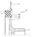
- FIG. 1 shows a first embodiment of the electromagnetic clutch of the present disclosure.
- 2 shows an inner hub 71, a coupling rubber 73, and an outer ring 72 of the electromagnetic clutch shown in FIG.
- FIG. 3 shows a side view in the direction of arrow III in FIG.
- the rotor 4 is fitted with a bearing 9 that is rotatably assembled.
- the rotor 4 is a component of the magnetic circuit, and a magnetic circuit is formed by energizing the electromagnetic coil 1 of the housing 2 serving as a stator.
- the clutch plate 5 serving as an armature is attracted to the end face of the rotor 4 by electromagnetic force. Power to the compressor. When the energization to the electromagnetic coil 1 is interrupted, the electromagnetic force disappears, and the clutch plate 5 is pulled away from the rotor 4 via the rivet 51 by the restoring force of the coupling rubber 73, and the clutch plate 5 is disengaged from the rotor 4. Blocked.
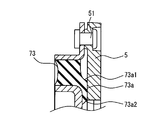
- the protrusion 73 a on the radially inner side of the coupling rubber 73 is in contact with the clutch plate 5.
- the protrusion 73a may protrude in the axial direction from the clutch plate side, it protrudes from the coupling rubber side in this embodiment.
- the coupling rubber 73 draws the clutch plate 5 toward the user through the rivet 51.
- the protrusion 73 a on the radially inner side of the rubber is in strong contact with the clutch plate 5.
- the protrusion 73a has a flat tip as shown in FIG. 2, but inclined surfaces 73a1 and 73a2 are provided on the radially inner side (rotary shaft side) and the outer side of the protrusion 73a, and protrude in the direction of the clutch plate 5. .
- the contact area between the projection 73a and the clutch plate 5 is reduced by the inclined surfaces 73a1 and 73a2.
- the protrusion 73a has a tapered shape having inclined surfaces (73a1, 73a2) on both radial sides of the protrusion.
- the electromagnetic coil 1 when the clutch is ON, the electromagnetic coil 1 is energized, the clutch plate 5 serving as an armature is attracted to the rotor 4 and comes into contact with the end surface of the rotor 4, and the clutch plate 5 and the rotor 4 are integrated to transmit power to the inner hub 71. This is transmitted to the rotating shaft 6.
- the coupling rubber 73 is deformed by pulling the clutch plate 5 toward the user through the rivet 51, and the radially inner side of the rubber is in strong contact with the clutch plate 5 as a reaction force.
- the coupling rubber 73 molded integrally with the inner hub 71 is in contact with the clutch plate 5 to suppress the resonance between the clutch plate 5 and the rotor 4 and reduce the operating noise.
- the electromagnetic clutch includes an electromagnetic coil 1 provided on the housing 2 side and a rotor 4 rotatably supported by the housing 2, and the electromagnetic clutch is energized by the electromagnetic coil 1.
- the clutch plate 5 is attracted to the rotor 4 by the magnetic force.
- the electromagnetic clutch has a cup provided with an inner hub 71 attached to the rotary shaft 6 inserted through the inner periphery of the housing 2 and a coupling rubber 73 for connecting the opposing peripheral surfaces of the outer ring 72 attached to the clutch plate 5.
- a ring 7 is provided.
- the electromagnetic clutch includes a protrusion 73 a interposed between the inner hub 71 and the clutch plate 5.
- the outer ring 72 is attached to the clutch plate 5 on the side opposite to the rotor 4, and has an opposing peripheral surface that faces the inner hub 71 in the radial direction of the rotating shaft 6.
- the coupling rubber 73 connects the inner hub 71 and the opposed peripheral surface of the outer ring 72.
- the protrusion 73a is always in contact with the clutch plate 5 regardless of whether the electromagnetic coil 1 is energized or not.
- the contact area between the coupling rubber 73 and the clutch plate 5 is reduced by a projection 73a formed on the coupling rubber 73 or the clutch plate 5 side.
- the protrusion 73a of the coupling rubber 73 is always in contact with the clutch plate 5 regardless of whether the electromagnetic coil 1 is energized or not. Thereby, generation
- the inventor has paid attention to the fact that this contact causes the deformation of the coupling rubber 73 and an internal stress is generated in the coupling rubber 73 due to the deformation. This stress acts in the direction in which the coupling rubber 73 is separated from the rotor 4. Since a part of the coupling rubber 73 is always in contact with the clutch plate 5 regardless of whether the electromagnetic coil 1 is energized or not, the coupling rubber 73 is deformed by a reaction force.
- the contact surface between the coupling rubber 73 and the clutch plate 5 is provided with a protrusion 73 a formed on the coupling rubber 73. As a result, both the adhesion and internal stress between the coupling rubber 73 and the clutch plate 5 are weakened.
- an electromagnetic clutch that does not require an increase in the attractive force of the electromagnetic coil 1 when the clutch plate 5 is attracted to the rotor 4 side while suppressing the vibration of the clutch plate 5 by the coupling rubber 73 and causing the noise to be silenced can be obtained.
- 12A to 14B are experimental evaluations of various structures.
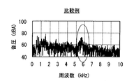
- 12A and 12B show a first comparative example of the present disclosure, in which the clutch plate 5 is separated from the coupling rubber 73 at both ON and OFF states, that is, regardless of energization / non-energization. In this case, a strong operating sound is generated in the vicinity of 6 kHz when ON.
- 13A and 13B show a second comparative example of the present disclosure, in which the radially outer side of the coupling rubber is coupled to the clutch plate both when it is ON and when it is OFF. In the configuration shown in FIG. 13A, as shown in FIG. 13B, the operating sound in the vicinity of 6 kHz is relieved when turned on, but the shape of the coupling rubber 73 is special, which causes an increase in cost.
- FIGS. 14A and 14B show an embodiment of the present disclosure in which the clutch plate 5 and the coupling rubber 73 are in contact with each other by a protruding portion 73a on the radially inner side both when turned on and when turned off. Therefore, in the embodiment of the present disclosure, only a part below the coupling rubber 73 is in contact with the clutch plate by the protrusion 73a. As for this, the operating sound is canceled in the vicinity of 6 kHz when ON. As can be seen from these evaluation results, the noise reduction effect due to vibration suppression is more effective when the coupling rubber 73 is applied to the clutch plate 5 at the radial inner side than at the radial outer side. In the embodiment of the present disclosure, as shown in FIG.
- the radially inner protrusion 73 a of the coupling rubber 73 is applied to the clutch plate 5 regardless of whether the electromagnetic coil 1 is electromagnetically or not electromagnetically.
- a protrusion 73a is formed on the radially inner side of the coupling rubber 73 to reduce the contact area with the clutch plate 5, and the protrusion 73a facilitates deformation of the coupling rubber and reduces internal stress. .
- the coupling rubber 73 and the clutch plate 5 are separated from each other when the clutch is ON, the coupling rubber 73 has a small effect of reducing the impact sound when the clutch is ON.
- the coupling rubber 73 and the clutch plate 5 are in contact with each other when the clutch is ON, there is a trade-off that the electromagnetic force of the electromagnetic coil 1 must be strengthened.
- the electromagnetic clutch includes the electromagnetic coil 1 provided in the housing 2 and the rotor 4 rotatably supported by the housing 2.
- the electromagnetic clutch includes a clutch plate 5 that is attracted to the rotor 4 by a magnetic force when the electromagnetic coil 1 is energized.
- an electromagnetic clutch connects the inner hub 71 attached to the rotary shaft 6 inserted through the inner periphery of the housing 2 and a coupling rubber 73 connecting the outer peripheral surface of the outer ring 72 attached to the clutch plate 5 with respect to the inner hub 71.
- the electromagnetic clutch is provided with a protrusion 73a protruding in the axial direction of the rotor 4 from the coupling rubber 73 side or the clutch plate 5 side.
- the coupling rubber 73 and the clutch plate 5 are in contact with each other between the center of the coupling rubber 73 and the rotary shaft 6 regardless of whether the electromagnetic coil 1 is energized or not only through the tip of the protrusion 73a.
- the contact area of the coupling rubber 73 with respect to the clutch plate 5 is reduced by the protrusion 73a.
- the clutch plate 5 and the coupling rubber 73 are projected on the rotating shaft 6 side from the intermediate position between the outer ring 72 and the inner hub 71 in the coupling rubber 73 regardless of whether the electromagnetic coil 1 is energized or not. You may contact via 73a.
- This stress acts in the direction in which the coupling rubber 73 is separated from the rotor 4.
- a part of the coupling rubber 73 is always in contact with the clutch plate 5 regardless of whether the electromagnetic coil 1 is energized or not, so that the coupling rubber 73 is deformed by a reaction force.
- the internal stress is large.
- the electromagnetic coil 1 needs a stronger attractive force, and the electromagnetic coil 1 needs to be enlarged. This is because if the amount of deformation is large, the internal stress and the close contact force between the coupling rubber 73 and the clutch plate 5 increase, and it is necessary to release the internal stress and close contact so that the clutch plate 5 is attracted to the rotor 4 side. It is.
- the contact of the coupling rubber 73 to the clutch plate 5 is eliminated, the essential silencing action is lost.
- a protrusion 73 a formed on the coupling rubber 73 or the clutch plate 5 side is provided on the contact surface between the coupling rubber 73 and the clutch plate 5.
- the contact area is reduced. That is, the adhesion and internal stress between the coupling rubber 73 and the clutch plate 5 are weakened.
- a complicated structure is not required. That is, the clutch can be turned on with an inexpensive and simple structure without deteriorating the operability of the clutch.
- FIG. 4 illustrates a second embodiment of the present disclosure.
- the protrusion 73a is formed between a plurality of grooves formed radially in the radial direction.
- the protrusion 73a is formed on the contact surface of the coupling rubber 73 to the clutch plate 5.
- the projection 73a is formed on the contact surface of the coupling rubber 73 to the clutch plate 5
- the elasticity of the coupling rubber 73 is weakened by the projection 73a.
- the adhesion force and internal stress between the coupling rubber 73 and the clutch plate 5 are weakened, and the size of the electromagnetic coil 1 can be suppressed while suppressing the vibration of the clutch plate 5 by the coupling rubber 73.
- the coupling rubber 73 is provided with a slit-like groove 73m in the radial direction so as not to impair the operability of the clutch, and the coupling rubber 73 has a protrusion 73a that is partially in contact with the coupling rubber 73.
- the structure provided may be sufficient.
- FIG. 5 is a modification of the second embodiment, and the shape of the protrusion is rectangular in cross section. The plurality of protrusions 73a are connected via a thin web portion 73w at the bottom of the groove 73m.
- the width of the groove 73m and the width of the protrusion 73a are made equal to form a rectangular protrusion 73a. That is, the protrusion 73a does not require the inclined surfaces 73a1 and 73a2 as shown in FIG.
- FIG. 6 is a third embodiment of the present disclosure.
- the protrusion 73 a is formed in a mountain shape on both sides with the circumferential groove 73 m as a valley.
- FIG. 7 shows a first modification of the third embodiment.
- the protrusion 73a has a triangular cross section and is formed in a streak shape on both sides of the circumferential groove 73m.
- the groove 73m is formed in a streak shape in the circumferential direction, and the protrusions 73a are connected to each other by a web portion 73w that forms the bottom of the groove 73m.
- FIG. 8 shows a second modification of the third embodiment.
- the protrusion 73a has a semicircular cross section and is formed in a streak shape on both sides of the circumferential groove 73m.
- the groove 73m is formed in a streak shape in the circumferential direction, and the protrusions 73a are connected to each other by a web portion 73w that forms the bottom of the groove 73m.
- the protrusion 73 a is formed adjacent to the groove 73 m extending in the circumferential direction of the rotor 4.
- the protrusion 73a can be easily formed by forming the groove 73m extending in the circumferential direction of the rotor 4.
- FIG. 9 is a fourth embodiment of the present disclosure.
- the protrusion 73a protrudes in the circumferential direction, and no groove is specifically formed.
- the protrusion 73a protrudes toward the clutch plate 5 in a streak-like and annular manner.
- the protrusion 73a is always in contact with the clutch plate.
- the contact area of the contact surface between the coupling rubber 73 and the clutch plate 5 is reduced by a protrusion 73a having inclined surfaces 73a1 and 73a2 formed on the coupling rubber 73.
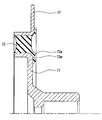
- the protrusion is formed on the coupling rubber side, but the iron protrusion 73a provided on the clutch plate 5 may contact the surface of the coupling rubber 73 as shown in FIG. That is, also in this case, the coupling rubber 73 and the clutch plate are interposed between the center of the coupling rubber 73 and the rotating shaft 6 only through the tip of the protrusion 73a regardless of whether the electromagnetic coil 1 is energized or not. 5 is in contact.
- the protrusion 73a is formed on the contact surface of the clutch plate 5 with the coupling rubber 73, the deformation of the coupling rubber 73 at the contact portion between the clutch plate 5 and the coupling rubber 73 is easy. The internal stress decreases. Accordingly, when the clutch plate 5 is attracted and moved by the rotor, a strong attractive force by the electromagnetic coil becomes unnecessary, and the enlargement of the electromagnetic coil 1 can be avoided.
- the protrusion may be formed by metal processing on the contact surface to the clutch plate 5, and the protrusion 73 a of the clutch plate 5 may be in contact with the flat surface of the coupling rubber 73.
- the protrusion 73a is formed on the contact surface to the clutch plate 5. Therefore, the deformation of the coupling rubber (73) at the contact portion between the clutch plate 5 and the coupling rubber (73) is facilitated. Accordingly, when the clutch plate 5 is attracted and moved by the rotor, a strong attractive force by the electromagnetic coil 1 is not required, and the size of the electromagnetic coil 1 can be suppressed.
Landscapes
- Engineering & Computer Science (AREA)
- General Engineering & Computer Science (AREA)
- Physics & Mathematics (AREA)
- Electromagnetism (AREA)
- Mechanical Engineering (AREA)
- Hydraulic Clutches, Magnetic Clutches, Fluid Clutches, And Fluid Joints (AREA)
- Connection Of Motors, Electrical Generators, Mechanical Devices, And The Like (AREA)
Abstract
電磁クラッチは、ハウジング(2)に設けられた電磁コイル(1)と、ハウジング(2)に回転自在に支持されたロータ(4)と、電磁コイル(1)が通電されたときの磁力によってロータ(4)に吸着されるクラッチ板(5)と、を備える。また電磁クラッチは、ハウジング(2)の内周に挿通された回転軸(6)に取り付けられるインナハブ(71)と、クラッチ板(5)に取り付けられるアウターリング(72)の対向周面間をカップリングゴム(73)で連結してなるカップリング(7)を備える。そしてカップリングゴム(73)の回転軸(6)側である径方向内側の一部は、電磁コイル(1)への通電非通電にかかわらず、常にクラッチ板(5)に接触している。クラッチの作動性を悪化させることなく、安価で簡素な構造でクラッチON時アーマチャとロータが当接する際の作動音を低減できる。
Description
本出願は、当該開示内容が参照によって本出願に組み込まれた、2014年3月5日に出願された日本特許出願2014-043139を基にしている。
本開示は、回転動力を被駆動部材に伝達する電磁クラッチに関する。特には車両用空調の圧縮機を駆動する電磁クラッチの消音構造に関するものである。
従来、電磁クラッチとして、エンジン等の外部動力源から、ベルトを介して運転される電磁クラッチが知られている。この電磁クラッチは、図10に示すように、ステータの電磁コイル1に通電されることで磁気回路が形成され、アーマチャのクラッチ板5が電磁力でロータ4に吸引されて圧縮機の回転軸6に動力を伝達する。また、通電を遮断することで電磁力は消滅し、アウターリング72とインナハブ71との間にあるカップリングゴム73の復帰力でクラッチ板5は、ロータ4から釈放され、動力が遮断される。
図10では、カップリングゴム73の復帰力で、クラッチ板5がロータ4から釈放された状態を図示している。このとき、カップリングゴム73とクラッチ板5とはカップリングゴム(73)の中心よりも回転軸(6)側の径方向内側730にて接触している。接触部には圧縮力が働いている。
このカップリングゴム73は、図10の状態つまりクラッチOFF時には、カップリングゴム73の径方向内側730がクラッチ板5に接触しているが、クラッチON時にはカップリングゴム73の径方向内側730とクラッチ板5とは基本的に離隔する。
特許文献1は、クラッチ板5がロータ4の端面に吸着される際の干渉音を、有効に低減すために次の構成を備える。
図11のように、この特許文献1の電磁クラッチは、電磁コイル1を通電することによりロータ4の端壁部にクラッチ板5を吸着して、ロータ4の回転トルクをカップリングゴム73を介して回転軸6へ与える。クラッチ板5の内周部に、内周側へ突出した複数の掛合爪5aが形成されている。
図11では、カップリングゴム73の下方の一部がクラッチ板に当接しているがクラッチ板に設けた溝の中にカップリングゴム73の一部を突出させ形状が複雑である。
カップリング7のカップリングゴム73の内周部に引張弾性体77が一体的に形成され、その円周方向に延びる掛合溝77aが各掛合爪5aと回転軸方向に掛合している。クラッチ板5がロータ4側へ移動する過程では、カップリングゴム73の剪断ばね力と、引張弾性体77の引張ばね力とによって、磁力によるクラッチ板5の加速が抑制され、ロータ4の端面にクラッチ板5が吸着される際の干渉音が低減される。
上記特許文献1の技術によると、引張弾性体77の形状が複雑であり、コストアップの要因になる。
本開示は、上記点に鑑み、クラッチの作動性を悪化させることなく、安価かつ簡素な構造でクラッチがONし、アーマチャとロータが当接する際の作動音を低減できる電磁クラッチを提供することを目的とする。
従来技術として列挙された特許文献の記載内容は、この明細書に記載された技術的要素の説明として、参照によって導入ないし援用することができる。
本開示の一態様によると、電磁クラッチは、ハウジングに設けられた電磁コイルと、前記ハウジングに回転自在に支持されたロータと、前記電磁コイルが通電されたときの磁力によって前記ロータに吸着されるクラッチ板と、前記ハウジングの内周に挿通された回転軸に取り付けられるインナハブと、前記クラッチ板に取り付けられるアウターリングと、前記アウターリングの内周面と前記アウターリングの前記内周面と対向する前記インナハブの外周面とを連結しているカップリングゴムと、前記カップリングゴム又は前記クラッチ板から前記ロータの軸方向に突出した突起部と、を備える。前記突起部の先端のみを介して、前記電磁コイルへの通電にかかわらず、前記カップリングゴムの中心と前記回転軸との間において、前記クラッチ板と前記カップリングゴムとは接触しており、前記カップリングゴムと前記クラッチ板との間の接触面積が軽減されている。
これによれば、カップリングゴムの一部は、電磁コイルへの通電にかかわらずクラッチ板に接触している。これにより、カップリングゴムの防振作用によりクラッチ板のロータへの衝突に伴う音の発生を抑制することができる。発明者は今回、この接触が、カップリングゴムの変形をもたらし、カップリングゴムの内部に変形に伴なった内部応力が生じていることに着目した。
この応力は、カップリングゴムをロータ側から離す方向に作用する。カップリングゴムの径方向内側が、電磁コイルへの通電非通電にかかわらずクラッチ板に当接していることにより、反力でカップリングゴムが変形する。
この変形量が多いと、上記内部応力が大きい。すると、クラッチ板がロータに吸着されて移動するときに、電磁コイルに、より強い吸引力が必要となり、電磁コイルの大型化が必要となることを見出した。これは変形量が多いと、カップリングゴム内の内部応力とクラッチ板に退位する密着力が増し、この内部応力と密着力とを解いて、クラッチ板がロータ側に吸引される必要があるからである。クラッチON時のカップリングゴムのクラッチ板への接触を無くすと、肝心の消音作用がなくなる。
要するに、カップリングゴムとクラッチ板とが接触しなくなると消音作用がなくなる。カップリングゴムとクラッチ板とを当接させるとカップリングゴムの内部応力と密着力でクラッチ板を吸引するのに大きな力が必要になる。この背反現象を解消するために、本開示においては、カップリングゴムとクラッチ板の接触面は、カップリングゴム又はクラッチ板側から軸方向に突出する突起部によって形成した。この突起部によって接触面積及びカップリングゴムの内部応力が軽減されている。
これにより、カップリングゴムとクラッチ板との密着力が弱くなる。また、カップリングゴムの内部応力が減少し、クラッチ板の振動を抑え、消音させながらクラッチ板が、ロータ側に吸引されるときの電磁コイルの吸引力の増大を要求しない電磁クラッチが得られる。さらに、クラッチの作動性を悪化させることなく、安価かつ簡素な構造でクラッチがONできる。
以下に、図面を参照しながら本開示を実施するための複数の形態を説明する。各形態において先行する形態で説明した事項に対応する部分には同一の参照符号を付して重複する説明を省略する場合がある。各形態において構成の一部を説明している場合は、構成の他の部分については先行して説明した他の形態を適用することができる。
各実施形態で具体的に組合せが可能であることを明示している部分同士の組合せばかりではなく、特に組合せに支障が生じなければ、明示していなくても実施形態同士を部分的に組合せることも可能である。
(第1実施形態)
以下、本開示の第1実施形態について図1ないし図3を用いて詳細に説明する。図1は、本開示の電磁クラッチの第1実施形態を示す。図2は図1の電磁クラッチのインナハブ71とカップリングゴム73とアウターリング72とを示す。図3は図2の矢印III方向に見た側面を示す。
以下、本開示の第1実施形態について図1ないし図3を用いて詳細に説明する。図1は、本開示の電磁クラッチの第1実施形態を示す。図2は図1の電磁クラッチのインナハブ71とカップリングゴム73とアウターリング72とを示す。図3は図2の矢印III方向に見た側面を示す。
図1~3に示すように、外部からの動力がVベルトによってロータ4に伝達される。ロータ4には回転自在に組みつけられたベアリング9がはめ込まれている。このロータ4は磁気回路の構成部品であり、ステータとなるハウジング2の電磁コイル1に通電されることで磁気回路が形成され、アーマチャとなるクラッチ板5が電磁力でロータ4の端面に吸引されて圧縮機に動力を伝達する。電磁コイル1への通電が遮断されると電磁力は消滅しカップリングゴム73の復帰力でリベット51を介してクラッチ板5を左方に引っ張り、クラッチ板5がロータ4から離脱し、動力が遮断される。この状態においても、図1に示すようにカップリングゴム73の径方向内側の突起部73aがクラッチ板5に接触している。突起部73aはクラッチ板側から軸方向に突出してもよいが、この実施形態ではカップリングゴム側から突出している。
カップリングゴム73はリベット51を介してクラッチ板5を自分のほうに引き寄せている。この反力としてゴムの径方向内側の突起部73aがクラッチ板5に強く接触している。突起部73aは、図2に示すように先端が平坦であるが、突起部73aの径方向内側(回転軸側)と外側とに傾斜面73a1、73a2が設けられクラッチ板5方向に突出している。傾斜面73a1、73a2によって突起部73aとクラッチ板5との接触面積が小さくなっている。言い換えれば、突起部73aは、該突起部の径方向両側に傾斜面(73a1、73a2)を持っている先細の形状を有している。
上記構造において、クラッチON時には電磁コイル1に通電され、アーマチャとなるクラッチ板5がロータ4に引き寄せられてロータ4の端面に当接し、クラッチ板5とロータ4とが一体となり動力をインナハブ71の回転軸6に伝達する。この際、カップリングゴム73は、リベット51を介してクラッチ板5を自分のほうに引き寄せて、反力としてゴムの径方向内側がクラッチ板5に強く接触して変形している。クラッチON時には上記変形状態から開放される必要がある。従って、反力としてカップリングゴム73の径方向内側がクラッチ板5に強く接触している変形状態が大きいほどクラッチ板5がロータ4側に引き寄せられてロータ4の端面に当接するに必要な電磁吸引力が大きくなる。
クラッチON時もインナハブ71と一体に成型されたカップリングゴム73は、クラッチ板5と接触しており、クラッチ板5とロータ4との共振を抑制するとともに、作動音が低減される。
この実施形態では、電磁クラッチが、ハウジング2側に設けられた電磁コイル1と、ハウジング2に回転自在に支持されたロータ4と、を備え、かつ電磁クラッチが、電磁コイル1が通電されたときの磁力によってロータ4に吸着されるクラッチ板5を有する。また電磁クラッチは、ハウジング2の内周に挿通された回転軸6に取り付けられるインナハブ71と、クラッチ板5に取り付けられるアウターリング72の対向周面間を連結するカップリングゴム73と、を備えるカップリング7を備える。更に電磁クラッチは、インナハブ71とクラッチ板5の間に介在された突起部73aを備える。すなわち、アウターリング72は、クラッチ板5におけるロータ4とは反対側に取り付けられ、回転軸6の径方向でインナハブ71に対向する対向周面を有する。カップリングゴム73は、インナハブ71、およびアウターリング72の対向周面との間を連結する。
そして突起部73aは、電磁コイル1への通電非通電にかかわらず常にクラッチ板5に接触している。かつカップリングゴム73とクラッチ板5との接触面はカップリングゴム73又はクラッチ板5側に形成された突起部73aによって接触面積が軽減されている。
これによれば、カップリングゴム73の突起部73aは、電磁コイル1への通電非通電にかかわらず常にクラッチ板5に接触している。これにより、クラッチ板5のロータ4への衝突に伴う音の発生を抑制することができる。発明者は今回、この接触がカップリングゴム73の変形をもたらし、カップリングゴム73の内部に変形に伴った内部応力が生じていることに着目した。この応力はカップリングゴム73をロータ4から離れさせる方向に作用する。カップリングゴム73の一部が、電磁コイル1への通電非通電にかかわらず常にクラッチ板5に当接していることにより、反力でカップリングゴム73が変形する。この変形量が多いと上記内部応力が大きい。すると、クラッチ板5がロータ4に吸着されて移動するときに電磁コイル1に、より強い吸引力が必要となり、電磁コイル1の大型化が必要となることを見出した。これは変形量が多いとカップリングゴム73とクラッチ板5との密着力及び内部応力が増しこの内部応力及び密着を解いて、クラッチ板5がロータ4側に吸引される必要があるからである。カップリングゴム73のクラッチ板5への接触を無くすと、肝心の消音作用がなくなる。
要するに、カップリングゴム73とクラッチ板5が接触しなくなると消音作用がなくなり、カップリングゴム73とクラッチ板5が強く接触するとカップリングゴム73の弾力でクラッチ板5を吸引するのに大きな力が必要に成る。この背反現象を解消するために本開示においては、カップリングゴム73とクラッチ板5との接触面はカップリングゴム73に形成された突起部73aを設けた。これにより、カップリングゴム73とクラッチ板5との密着力及び内部応力が共に弱くなる。かつ、カップリングゴム73によりクラッチ板5の振動を抑え消音させながらクラッチ板5がロータ4側に吸引されるときの電磁コイル1の吸引力の増大を要求しない電磁クラッチが得られる。
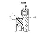
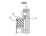
図12Aから図14Bは、各種構造の実験評価である。図12A、12Bは本開示の第1比較例を示し、クラッチ板5がカップリングゴム73とON時もOFF時も、つまり通電非通電にかかわらず離れている。これではON時に6khz付近に強い作動音が発生する。図13A、13Bは本開示の第2比較例を示し、クラッチ板にカップリングゴムの径方向外側がON時もOFF時も結合されている。この図13Aに示す構成では、図13Bに示すようにON時に6khz付近の作動音が緩和されているが、カップリングゴム73の形状が特殊でありコストアップの要因になる。
図14A、14Bはクラッチ板5とカップリングゴム73とがON時もOFF時も径方向内側の突起部73aで接触している本開示の実施形態である。したがって、本開示の実施形態では、カップリングゴム73の下方の一部だけが突起部73aによって、クラッチ板に当接している。これはON時に6khz付近に作動音が解消されている。これらの評価結果からもわかるように、制振による異音低減効果は径方向外側でカップリングゴム73をクラッチ板5に当てるよりも径方向内側にてクラッチ板5に当てたほうが効果が大きい。本開示の実施形態では、図14Aに示すように、カップリングゴム73の径方向内側の突起部73aをクラッチ板5に電磁コイル1の通電磁非通電磁にかかわらず当てている。効果を得るためにはクラッチON(電磁コイル通電磁時)にカップリングゴム73がクラッチ板5に当たっている必要がある。ON時に当たっていないと制振効果がえられない。
なお、カップリングゴム73の表面は粘着するのを防ぐために粘着防止塗料を塗布している。カップリングゴム73の径方向内側に突起部73aを形成してクラッチ板5との接触面積を減少させ、かつ、突起部73aによりカップリングゴムの変形を容易にし、内部応力を軽減することができる。
今回の実験で、図12A、12Bに示すように、クラッチON時にはカップリングゴム73とクラッチ板5とが離隔していると、カップリングゴム73のクラッチON時の衝撃音を緩和する作用が小さいことが判明した。また、電磁コイル1から見れば、クラッチ板5を吸引するときに、吸引前に存在するカップリングゴム73の内部応力に抗してカップリングゴム73を変形させなければならない。かつ、カップリングゴム73とクラッチ板5との接触状態を離間状態にしなければならない。これにより大きな駆動力が要求されることが判明した。よって、大きな駆動力を必要としないで、電磁クラッチがONする際に発生する作動音及び共振による異音を低減させることが好ましい。
換言すれば、クラッチON時にはカップリングゴム73とクラッチ板5とが離隔しているようにすると、カップリングゴム73にはクラッチON時の衝撃音を緩和する作用が小さい。一方、クラッチON時にカップリングゴム73とクラッチ板5とが接触しているようにすると、電磁コイル1の電磁力の強化をしなければならない二律背反がある。
第1実施形態の作用効果について以下説明する。上記第1実施形態においては、図1のように、電磁クラッチがハウジング2に設けられた電磁コイル1と、ハウジング2に回転自在に支持されたロータ4とを備えている。また、電磁クラッチは電磁コイル1が通電されたときの磁力によってロータ4に吸着されるクラッチ板5を備える。
また電磁クラッチが、ハウジング2の内周に挿通された回転軸6に取り付けられるインナハブ71と、クラッチ板5に取り付けられるアウターリング72のインナハブ71に対する対向周面間を連結しているカップリングゴム73とを備える。
更に電磁クラッチが、カップリングゴム73側又はクラッチ板5側からロータ4の軸方向に突出した突起部73aを備える。
そして突起部73aの先端のみを介して、電磁コイル1への通電非通電にかかわらず、カップリングゴム73の中心と回転軸6との間で、カップリングゴム73とクラッチ板5とが接触しており、突起部73aによってカップリングゴム73のクラッチ板5に対する接触面積が軽減されている。クラッチ板5およびカップリングゴム73は、電磁コイル1への通電非通電にかかわらず、カップリングゴム73におけるアウターリング72とインナハブ71との間の中間位置よりも回転軸6側にて、突起部73aを介して接触してもよい。
これにより、クラッチ板5のロータ4への衝突に伴う音の発生を抑制することができる。この接触がカップリングゴム73の変形をもたらし、カップリングゴム73の内部に、変形に伴う内部応力が生じている。
この応力は、カップリングゴム73をロータ4から離す方向に作用する。カップリングゴム73の一部は、電磁コイル1への通電非通電にかかわらず常にクラッチ板5に当接していることにより、反力でカップリングゴム73が変形する。この変形量が多いと、上記内部応力が大きい。すると、クラッチ板5がロータ4に吸着されて移動するときに、電磁コイル1に、より強い吸引力が必要となり、電磁コイル1の大型化が必要となる。これは変形量が多いと、内部応力及びカップリングゴム73とクラッチ板5との密着力が増し、この内部応力及び密着を解いて、クラッチ板5がロータ4側に吸引される必要があるからである。カップリングゴム73のクラッチ板5への接触を無くすと、肝心の消音作用がなくなる。
要するに、カップリングゴム73とクラッチ板5とが接触しなくなると消音作用がなくなり、カップリングゴム73とクラッチ板5と当接するとカップリングゴム73の弾力でクラッチ板5を吸引するのに大きな力が必要になる。この背反現象を解消するために、本開示においては、カップリングゴム73とクラッチ板5の接触面に、カップリングゴム73又はクラッチ板5側に形成された突起部73aを設けた。これによって、接触面積が軽減されている。つまり、カップリングゴム73とクラッチ板5との密着力及び内部応力が弱くなる。その結果、カップリングゴム73によりクラッチ板5の振動を抑え、消音させながらクラッチ板5が、ロータ4側に吸引されるときの電磁コイル1の吸引力の増大を要求しない電磁クラッチが得られる。また、複雑な構造を必要としない。すなわち、クラッチの作動性を悪化させることなく、安価かつ簡素な構造でクラッチがONできる。
(第2実施形態)
次に、本開示の第2実施形態について説明する。なお、以降の各実施形態においては、上記した第1実施形態と同一の構成要素には同一の符号を付して説明を省略し、異なる構成について説明する。なお、第2実施形態以下については、第1実施形態と同じ符号は、同一の構成を示すものであって、先行する説明が援用される。図4は、本開示の第2実施形態を示す。図4において、突起部73aは径方向に放射状に形成された複数の溝相互間に形成されている。
次に、本開示の第2実施形態について説明する。なお、以降の各実施形態においては、上記した第1実施形態と同一の構成要素には同一の符号を付して説明を省略し、異なる構成について説明する。なお、第2実施形態以下については、第1実施形態と同じ符号は、同一の構成を示すものであって、先行する説明が援用される。図4は、本開示の第2実施形態を示す。図4において、突起部73aは径方向に放射状に形成された複数の溝相互間に形成されている。
また突起部73aは、カップリングゴム73のクラッチ板5への接触面に形成されている。このように突起部73aはカップリングゴム73のクラッチ板5への接触面に形成されているから、突起部73aによってカップリングゴム73の弾力が弱められる。また、カップリングゴム73とクラッチ板5との密着力及び内部応力が弱くなり、カップリングゴム73によりクラッチ板5の振動を抑えながら、電磁コイル1の大型化を抑制できる。
また、図5に示すように、カップリングゴム73は、クラッチの作動性を損なわないように径方向にスリット状の溝73mを設けてカップリングゴム73が、部分的に接触する突起部73aを設ける構造でもよい。図5は、第2実施形態の変形例であり突起部の形状は、断面が長方形である。複数の突起部73aは、溝73mの底部の薄いウエブ部分73wを介してつながっている。図5は溝73mの幅と突起部73aの幅を等しくし矩形の突起部73aとしている。つまり、突起部73aは図2のように傾斜面73a1、73a2を必須としない。
(第3実施形態)
次に、本開示の第3実施形態について説明する。上記した実施形態と異なる部分を説明する。図6は、本開示の第3実施形態である。図6において、突起部73aは周方向の溝73mを谷として両側に山状に形成されている。
次に、本開示の第3実施形態について説明する。上記した実施形態と異なる部分を説明する。図6は、本開示の第3実施形態である。図6において、突起部73aは周方向の溝73mを谷として両側に山状に形成されている。
図7は第3実施形態の変形例1である。突起部73aは断面三角形であり、周方向の溝73mの両側に筋状に形成されている。溝73mは周方向に筋状に形成され、溝73mの底部を成すウエブ部分73wによって突起部73a相互間が連結されている。
図8は、第3実施形態の変形例2である。突起部73aは断面半円形であり、周方向の溝73mの両側に筋状に形成されている。溝73mは周方向に筋状に形成され、溝73mの底部を成すウエブ部分73wによって突起部73a相互間が連結されている。
第3実施形態の作用効果について以下説明する。上記実施形態においては、突起部73aは、ロータ4の周方向に延在する溝73mに隣接して形成されている。
これによれば、ロータ4の周方向に延在する溝73mを形成することにより、容易に突起部73aを形成できる。
(第4実施形態)
次に、本開示の第4実施形態について説明する。上記した実施形態と異なる部分を説明する。図9は、本開示の第4実施形態である。図9において、突起部73aは周方向に突出し、溝は特に形成されていない。
次に、本開示の第4実施形態について説明する。上記した実施形態と異なる部分を説明する。図9は、本開示の第4実施形態である。図9において、突起部73aは周方向に突出し、溝は特に形成されていない。
第4実施形態の作用効果について以下説明する。記第4実施形態においては突起部73aは、筋状かつ環状にクラッチ板5に向かって突出している。これにより突起部73aはクラッチ板に常に当接している。
この第4実施形態においては、カップリングゴム73とクラッチ板5との接触面はカップリングゴム73に形成された傾斜面73a1、73a2を持つ突起部73aによって接触面積が軽減されている。これにより、カップリングゴム73の内部応力及びカップリングゴム73とクラッチ板5との密着力が弱くなる。そのため、カップリングゴム73によりクラッチ板5の振動を抑え、消音させながらクラッチ板5がロータ側に吸引されるときの電磁コイル1の吸引力の増大を要求しない。
上記の実施形態では、本開示の好ましい実施形態について説明したが、本開示は上記した実施形態に何ら制限されることなく、本開示の主旨を逸脱しない範囲において種々変形して実施することが可能である。上記実施形態の構造は、あくまで例示であって、本開示の範囲はこれらの記載の範囲に限定されるものではない。
上記実施形態においては、突起部をカップリングゴム側に形成したが、図15のようにクラッチ板5に設けた鉄の突起部73aがカップリングゴム73の表面に接触するようにしてもよい。すなわち、この場合も、突起部73aの先端のみを介して、電磁コイル1への通電非通電にかかわらず、カップリングゴム73の中心と回転軸6との間で、カップリングゴム73とクラッチ板5とが接触している。これによれば、突起部73aは、クラッチ板5のカップリングゴム73との接触面に形成されているから、クラッチ板5とカップリングゴム73との接触部におけるカップリングゴム73の変形が容易になり内部応力が減少する。その分、クラッチ板5がロータに吸着されて移動するときに電磁コイルによる強い吸引力が不要となり、電磁コイル1の大型化が避けられる。
また、突起部がクラッチ板5のカップリングゴム73との接触面に形成されているからカップリングゴム73とクラッチ板5との密着力が減少し、この密着を解いてクラッチ板5がロータ側に容易に吸引される。つまり、カップリングゴムとクラッチ板との密着力と内部応力の双方が弱くなり、カップリングゴム73によりクラッチ板5の振動を抑え消音させながらクラッチ板5がロータ側に吸引されるときの電磁コイル1の吸引力の増大を要求しない電磁クラッチが得られる。ただし極端に突起部73aがカップリングゴム73に食い込む構成は密着力を増すため避ける必要ある。
つまり突起部は、クラッチ板5への接触面に金属加工で形成されており、クラッチ板5の突起部73aがカップリングゴム73の平坦な表面に接触していてもよい。
これによれば、突起部73aはクラッチ板5への接触面に形成されている。従って、クラッチ板5とカップリングゴム(73)との接触部におけるカップリングゴム(73)の変形が容易になる。その分、クラッチ板5がロータに吸着されて移動するときに電磁コイル1による強い吸引力が不要となり電磁コイル1の大型化が抑制できる。
これは突起部73aがクラッチ板5への接触面に形成されているから、カップリングゴム73とクラッチ板5との密着力と内部応力とが減少し、この密着力と内部応力とを解いてクラッチ板5がロータ4側に容易に吸引されるからである。これにより、クラッチ板5の振動を抑え消音させながらクラッチ板5がロータ側に吸引されるときの電磁コイル1の吸引力の増大を要求しない電磁クラッチが得られる。
Claims (8)
- ハウジング(2)に設けられた電磁コイル(1)と、
前記ハウジング(2)に回転自在に支持されたロータ(4)と、
前記電磁コイル(1)が通電されたときの磁力によって前記ロータ(4)に吸着されるクラッチ板(5)と、
前記ハウジング(2)の内周に挿通された回転軸(6)に取り付けられるインナハブ(71)と、
前記クラッチ板(5)に取り付けられるアウターリング(72)の前記インナハブ(71)に対する対向周面間を連結しているカップリングゴム(73)と、
前記カップリングゴム(73)又は前記クラッチ板(5)から前記ロータ(4)の軸方向に突出した突起部(73a)と、を備え、
前記突起部(73a)の先端のみを介して、前記電磁コイル(1)への通電にかかわらず、前記カップリングゴム(73)の中心と前記回転軸(6)との間において、前記クラッチ板(5)と前記カップリングゴム(73)とは接触しており、前記カップリングゴム(73)と前記クラッチ板(5)との間の接触面積が軽減されている電磁クラッチ。 - 前記突起部(73a)は、該突起部の径方向両側に傾斜面(73a1、73a2)を持つ先細の形状を有している請求項1に記載の電磁クラッチ。
- 前記突起部(73a)は前記カップリングゴム(73)の前記クラッチ板(5)への接触面に形成されている請求項1又は2に記載の電磁クラッチ。
- 前記カップリングゴム(73)は、前記ロータ(4)の径方向に延在する複数の溝(73m)を有し、
前記突起部(73a)は、前記複数の溝(73m)の間に形成されている請求項1から3のいずれか一項に記載の電磁クラッチ。 - 前記カップリングゴム(73)は、前記ロータ(4)の周方向に延在する複数の溝(73m)を有し、
前記突起部(73a)は、前記複数の溝(73m)の間に形成されている請求項1から3のいずれか一項に記載の電磁クラッチ。 - 前記突起部(73a)は、前記クラッチ板(5)の表面に形成されており、前記クラッチ板(5)の前記突起部(73a)が前記カップリングゴム(73)の表面に接触している請求項1又は2に記載の電磁クラッチ。
- ハウジング(2)に設けられた電磁コイル(1)と、
前記ハウジング(2)に回転自在に支持されたロータ(4)と、
前記電磁コイル(1)が通電されたときの磁力によって前記ロータ(4)に吸着されるクラッチ板(5)と、
前記ハウジング(2)の内周に挿通された回転軸(6)に取り付けられるインナハブ(71)と、
前記クラッチ板(5)における前記ロータ(4)とは反対側に取り付けられ、前記回転軸(6)の径方向で前記インナハブ(71)に対向する対向周面を有するアウターリング(72)と、
前記インナハブ(71)、および前記アウターリング(72)の対向周面との間を連結するカップリングゴム(73)と、
前記カップリングゴム(73)、および前記クラッチ板(5)のうち、一方の部材から前記ロータ(4)の軸方向に突出した突起部(73a)と、を備え、
前記クラッチ板(5)および前記カップリングゴム(73)は、前記電磁コイル(1)への通電非通電にかかわらず、前記突起部(73a)で接触している電磁クラッチ。 - 前記クラッチ板(5)および前記カップリングゴム(73)は、前記電磁コイル(1)への通電非通電にかかわらず、前記カップリングゴム(73)における前記アウターリング(72)と前記インナハブ(71)との間の中間位置よりも前記回転軸(6)側にて、前記突起部(73a)を介して接触している請求項7に記載の電磁クラッチ。
Applications Claiming Priority (2)
| Application Number | Priority Date | Filing Date | Title |
|---|---|---|---|
| JP2014043139A JP2015169233A (ja) | 2014-03-05 | 2014-03-05 | 電磁クラッチ |
| JP2014-043139 | 2014-03-05 |
Publications (1)
| Publication Number | Publication Date |
|---|---|
| WO2015133085A1 true WO2015133085A1 (ja) | 2015-09-11 |
Family
ID=54054904
Family Applications (1)
| Application Number | Title | Priority Date | Filing Date |
|---|---|---|---|
| PCT/JP2015/000862 Ceased WO2015133085A1 (ja) | 2014-03-05 | 2015-02-23 | 電磁クラッチ |
Country Status (2)
| Country | Link |
|---|---|
| JP (1) | JP2015169233A (ja) |
| WO (1) | WO2015133085A1 (ja) |
Cited By (2)
| Publication number | Priority date | Publication date | Assignee | Title |
|---|---|---|---|---|
| CN109983246A (zh) * | 2016-11-10 | 2019-07-05 | 株式会社电装 | 动力传递装置 |
| US11286997B2 (en) * | 2017-07-28 | 2022-03-29 | Denso Corporation | Power transmission device |
Citations (6)
| Publication number | Priority date | Publication date | Assignee | Title |
|---|---|---|---|---|
| JPS62167936U (ja) * | 1986-04-15 | 1987-10-24 | ||
| JPH022537U (ja) * | 1988-06-15 | 1990-01-09 | ||
| JP2000120791A (ja) * | 1998-10-13 | 2000-04-25 | Nok Megulastik Co Ltd | 電磁クラッチ用ダンパ装置 |
| JP2004162886A (ja) * | 2002-09-24 | 2004-06-10 | Nok Corp | 電磁クラッチ用カップリング |
| JP4524668B2 (ja) * | 2003-03-07 | 2010-08-18 | Nok株式会社 | 電磁クラッチ用カップリング |
| JP2013113382A (ja) * | 2011-11-29 | 2013-06-10 | Nok Corp | 電磁クラッチ用カップリング |
-
2014
- 2014-03-05 JP JP2014043139A patent/JP2015169233A/ja active Pending
-
2015
- 2015-02-23 WO PCT/JP2015/000862 patent/WO2015133085A1/ja not_active Ceased
Patent Citations (6)
| Publication number | Priority date | Publication date | Assignee | Title |
|---|---|---|---|---|
| JPS62167936U (ja) * | 1986-04-15 | 1987-10-24 | ||
| JPH022537U (ja) * | 1988-06-15 | 1990-01-09 | ||
| JP2000120791A (ja) * | 1998-10-13 | 2000-04-25 | Nok Megulastik Co Ltd | 電磁クラッチ用ダンパ装置 |
| JP2004162886A (ja) * | 2002-09-24 | 2004-06-10 | Nok Corp | 電磁クラッチ用カップリング |
| JP4524668B2 (ja) * | 2003-03-07 | 2010-08-18 | Nok株式会社 | 電磁クラッチ用カップリング |
| JP2013113382A (ja) * | 2011-11-29 | 2013-06-10 | Nok Corp | 電磁クラッチ用カップリング |
Cited By (3)
| Publication number | Priority date | Publication date | Assignee | Title |
|---|---|---|---|---|
| CN109983246A (zh) * | 2016-11-10 | 2019-07-05 | 株式会社电装 | 动力传递装置 |
| CN109983246B (zh) * | 2016-11-10 | 2020-09-08 | 株式会社电装 | 动力传递装置 |
| US11286997B2 (en) * | 2017-07-28 | 2022-03-29 | Denso Corporation | Power transmission device |
Also Published As
| Publication number | Publication date |
|---|---|
| JP2015169233A (ja) | 2015-09-28 |
Similar Documents
| Publication | Publication Date | Title |
|---|---|---|
| JP5451578B2 (ja) | 電磁クラッチ | |
| CN106838049B (zh) | 电磁离合器 | |
| WO2015133085A1 (ja) | 電磁クラッチ | |
| US20060204370A1 (en) | Electromagnetic clutch for compressor | |
| KR102476896B1 (ko) | 전자 클러치 | |
| JP2005344876A (ja) | 電磁クラッチ | |
| JP5879972B2 (ja) | 電磁クラッチ用カップリング | |
| JP6597746B2 (ja) | 動力伝達装置 | |
| EP1396662B1 (en) | An integrated pulley-torsional damper assembly | |
| JP2009281579A (ja) | 電磁クラッチ | |
| JP4412991B2 (ja) | 電磁式クラッチ | |
| JP2001221259A (ja) | カップリング | |
| JP6645415B2 (ja) | 動力伝達装置 | |
| KR101824437B1 (ko) | 압축기용 전자클러치의 디스크 및 허브 조립체 | |
| KR101901686B1 (ko) | 압축기용 전자클러치의 디스크 허브 조립체 | |
| KR101422331B1 (ko) | 압축기용 전자클러치의 디스크 및 허브 조립체 | |
| KR101644320B1 (ko) | 전자클러치의 디스크 및 허브 조립체 | |
| JP2002061673A (ja) | 電磁クラッチ | |
| WO2018088234A1 (ja) | 動力伝達装置 | |
| JP2005155699A (ja) | 電磁クラッチ | |
| JP4476197B2 (ja) | 動力伝達装置 | |
| KR20100065593A (ko) | 전자클러치의 디스크 및 허브 어셈블리 | |
| JPS60113825A (ja) | 電磁スプリングクラッチ | |
| WO2018047568A1 (ja) | 電磁クラッチ | |
| KR20160041454A (ko) | 압축기의 전자클러치용 풀리 |
Legal Events
| Date | Code | Title | Description |
|---|---|---|---|
| 121 | Ep: the epo has been informed by wipo that ep was designated in this application |
Ref document number: 15758206 Country of ref document: EP Kind code of ref document: A1 |
|
| NENP | Non-entry into the national phase |
Ref country code: DE |
|
| 122 | Ep: pct application non-entry in european phase |
Ref document number: 15758206 Country of ref document: EP Kind code of ref document: A1 |