WO2015129565A1 - デジタルシネマ映画館用のプロジェクタ装置 - Google Patents
デジタルシネマ映画館用のプロジェクタ装置 Download PDFInfo
- Publication number
- WO2015129565A1 WO2015129565A1 PCT/JP2015/054735 JP2015054735W WO2015129565A1 WO 2015129565 A1 WO2015129565 A1 WO 2015129565A1 JP 2015054735 W JP2015054735 W JP 2015054735W WO 2015129565 A1 WO2015129565 A1 WO 2015129565A1
- Authority
- WO
- WIPO (PCT)
- Prior art keywords
- projector
- digital cinema
- housing
- theater
- digital
- Prior art date
- Legal status (The legal status is an assumption and is not a legal conclusion. Google has not performed a legal analysis and makes no representation as to the accuracy of the status listed.)
- Ceased
Links
Images


Classifications
-
- G—PHYSICS
- G03—PHOTOGRAPHY; CINEMATOGRAPHY; ANALOGOUS TECHNIQUES USING WAVES OTHER THAN OPTICAL WAVES; ELECTROGRAPHY; HOLOGRAPHY
- G03B—APPARATUS OR ARRANGEMENTS FOR TAKING PHOTOGRAPHS OR FOR PROJECTING OR VIEWING THEM; APPARATUS OR ARRANGEMENTS EMPLOYING ANALOGOUS TECHNIQUES USING WAVES OTHER THAN OPTICAL WAVES; ACCESSORIES THEREFOR
- G03B21/00—Projectors or projection-type viewers; Accessories therefor
- G03B21/14—Details
- G03B21/16—Cooling; Preventing overheating
-
- A—HUMAN NECESSITIES
- A63—SPORTS; GAMES; AMUSEMENTS
- A63J—DEVICES FOR THEATRES, CIRCUSES, OR THE LIKE; CONJURING APPLIANCES OR THE LIKE
- A63J25/00—Equipment specially adapted for cinemas
-
- F—MECHANICAL ENGINEERING; LIGHTING; HEATING; WEAPONS; BLASTING
- F16—ENGINEERING ELEMENTS AND UNITS; GENERAL MEASURES FOR PRODUCING AND MAINTAINING EFFECTIVE FUNCTIONING OF MACHINES OR INSTALLATIONS; THERMAL INSULATION IN GENERAL
- F16M—FRAMES, CASINGS OR BEDS OF ENGINES, MACHINES OR APPARATUS, NOT SPECIFIC TO ENGINES, MACHINES OR APPARATUS PROVIDED FOR ELSEWHERE; STANDS; SUPPORTS
- F16M11/00—Stands or trestles as supports for apparatus or articles placed thereon ; Stands for scientific apparatus such as gravitational force meters
- F16M11/02—Heads
- F16M11/04—Means for attachment of apparatus; Means allowing adjustment of the apparatus relatively to the stand
- F16M11/043—Allowing translations
- F16M11/046—Allowing translations adapted to upward-downward translation movement
-
- F—MECHANICAL ENGINEERING; LIGHTING; HEATING; WEAPONS; BLASTING
- F16—ENGINEERING ELEMENTS AND UNITS; GENERAL MEASURES FOR PRODUCING AND MAINTAINING EFFECTIVE FUNCTIONING OF MACHINES OR INSTALLATIONS; THERMAL INSULATION IN GENERAL
- F16M—FRAMES, CASINGS OR BEDS OF ENGINES, MACHINES OR APPARATUS, NOT SPECIFIC TO ENGINES, MACHINES OR APPARATUS PROVIDED FOR ELSEWHERE; STANDS; SUPPORTS
- F16M11/00—Stands or trestles as supports for apparatus or articles placed thereon ; Stands for scientific apparatus such as gravitational force meters
- F16M11/02—Heads
- F16M11/18—Heads with mechanism for moving the apparatus relatively to the stand
-
- F—MECHANICAL ENGINEERING; LIGHTING; HEATING; WEAPONS; BLASTING
- F16—ENGINEERING ELEMENTS AND UNITS; GENERAL MEASURES FOR PRODUCING AND MAINTAINING EFFECTIVE FUNCTIONING OF MACHINES OR INSTALLATIONS; THERMAL INSULATION IN GENERAL
- F16M—FRAMES, CASINGS OR BEDS OF ENGINES, MACHINES OR APPARATUS, NOT SPECIFIC TO ENGINES, MACHINES OR APPARATUS PROVIDED FOR ELSEWHERE; STANDS; SUPPORTS
- F16M13/00—Other supports for positioning apparatus or articles; Means for steadying hand-held apparatus or articles
- F16M13/02—Other supports for positioning apparatus or articles; Means for steadying hand-held apparatus or articles for supporting on, or attaching to, an object, e.g. tree, gate, window-frame, cycle
- F16M13/027—Ceiling supports
-
- G—PHYSICS
- G03—PHOTOGRAPHY; CINEMATOGRAPHY; ANALOGOUS TECHNIQUES USING WAVES OTHER THAN OPTICAL WAVES; ELECTROGRAPHY; HOLOGRAPHY
- G03B—APPARATUS OR ARRANGEMENTS FOR TAKING PHOTOGRAPHS OR FOR PROJECTING OR VIEWING THEM; APPARATUS OR ARRANGEMENTS EMPLOYING ANALOGOUS TECHNIQUES USING WAVES OTHER THAN OPTICAL WAVES; ACCESSORIES THEREFOR
- G03B17/00—Details of cameras or camera bodies; Accessories therefor
- G03B17/56—Accessories
- G03B17/561—Support related camera accessories
-
- H—ELECTRICITY
- H04—ELECTRIC COMMUNICATION TECHNIQUE
- H04N—PICTORIAL COMMUNICATION, e.g. TELEVISION
- H04N9/00—Details of colour television systems
- H04N9/12—Picture reproducers
- H04N9/31—Projection devices for colour picture display, e.g. using electronic spatial light modulators [ESLM]
- H04N9/3141—Constructional details thereof
Definitions
- the present invention relates to a projector device for a digital cinema movie theater using, for example, a cinema complex.
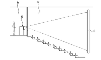
- a digital cinema by a cinema complex it is possible to simultaneously display different ones using a plurality of digital cinema projectors, and it is possible to centrally manage the operations of the digital cinema projectors. That is, in a theater that distributes video information (movies) using a projection film, as shown in FIG. 8, during movie screening, a movie room Pr is provided separately from the screening room (theater space Sr). The projection engineer who operates the projector 80 has to wait. This is because it is necessary to always check the state of the projector 80 and the screen S during the movie.
- a digital cinema is provided by sending a video signal to each digital cinema projector using a network such as a LAN, for example.
- Patent Document 2 and Patent Document 3 disclose a lift system for a projector that supports the projector by suspending it from the ceiling in order to make full use of the effective use of the theater space.
- a sufficiently large space for visitors can be secured in the theater space, and a more comfortable space design can be realized.
- the structure in which the projector for digital cinema is simply suspended from the ceiling and supported has the problem that the beauty of the theater is impaired.
- problems such as the uncomfortable feeling of the hot air generated by the exhaust in the seats near the projector for digital cinema, and the operating sound of the cooling mechanism can occur in the theater space.
- the present invention has been made based on the circumstances as described above, and the object thereof is to enable effective use of the theater space without impairing the beauty of the theater space, and from the projector for digital cinema. It is an object of the present invention to provide a projector device for a digital cinema movie theater that can solve the problems related to the exhaust and noise and provide a more comfortable theater space. Another object of the present invention is to provide a projector device for a digital cinema movie theater capable of easily and reliably performing maintenance work for the projector for digital cinema.
- a projector device for a digital cinema movie theater includes a housing fixed to a ceiling portion of a theater space, a digital cinema projector installed inside the housing, and the digital cinema projector suspended by wires.
- An elevating system that supports the bottom, The housing includes a housing body having a projection window formed on the front surface facing the screen and having an opening opening downward, and opens and closes the opening in the housing body to form a sealed space together with the housing body.
- a lid that The digital cinema projector is configured to be able to descend downward from the housing by the lifting system.
- a gantry supporting the digital cinema projector is fixed via an air cylinder on a lid that opens and closes the opening of the housing, and is attached to the gantry.
- the wire is fixed and the digital cinema projector is supported in a suspended state, It is preferable that the air cylinder is operated so as to maintain a pressed state of the lid body with respect to the housing body when supplied with pressurized air.
- the digital cinema projector includes a position restricting means for restricting the position of the digital cinema projector with respect to the housing body during the raising / lowering operation of the digital cinema projector,
- the position restricting means includes a guide rod provided in the gantry extending in the vertical direction, and a pair of guide rollers for guiding the guide rod provided with a rotation shaft fixed to the housing body. It is preferable that
- a projector apparatus for a digital cinema movie theater is a digital camera equipped with a casing that is fixed to the ceiling of a theater space and forms a sealed space inside, and a cooling mechanism that is installed inside the casing.
- a cinema projector, and an elevating system for supporting the digital cinema projector by suspending with a wire The wall in the housing is formed by a sound insulation panel,
- the housing includes a housing body having an opening that opens downward, and a lid that opens and closes the opening in the housing.
- the projector for digital cinema is mounted on the lid.
- a support base is fixed via an air cylinder, the wire is fixed to the base, and the projector for digital cinema is suspended and supported.
- the air cylinder is operated so as to maintain a pressing state of the lid body against the housing body when pressurized air is supplied.
- an airtight cushioning member made of an elastic body is provided on either the lid body or the housing body, and the lid body and the housing body. It is preferable that it is the structure provided in the state interposed between.
- a projector device for a digital cinema movie theater includes a housing that has an upper wall fixed to a ceiling portion of a theater space and that forms a sealed space inside, and a cooling mechanism that is installed inside the housing.
- a cooling air supply path and an exhaust path for cooling the digital cinema projector are formed so as to extend to the outside of the apparatus through the upper wall of the housing in a state of being isolated from the theater space,
- an exhaust duct having one end connected to an exhaust opening in the digital cinema projector is led out of the apparatus through an upper opening formed in the upper wall of the housing.
- the housing is configured to be openable and closable at the bottom, and includes an elevating system that supports the digital cinema projector so that it can be raised and lowered.
- the exhaust duct is formed of a bellows that can be expanded and contracted in the vertical direction of the digital cinema projector.
- the casing includes a casing main body having the upper opening and a lower opening opening downward, and opens and closes the lower opening in the casing main body. And a lid that Either one of the lid or the housing body is provided with an airtight cushioning member made of an elastic body in a state of being interposed between the lid and the housing body. Is preferred.
- a projector device for a digital cinema movie theater includes a housing that has an upper wall fixed to a ceiling portion of a theater space and that forms a sealed space inside, and a cooling mechanism that is installed inside the housing.
- a cooling air supply path and an exhaust path for cooling the digital cinema projector are formed so as to extend to the outside of the apparatus through the upper wall of the housing in a state of being isolated from the theater space, A cooling airflow passage through which cooling air for cooling the digital cinema projector is circulated is formed in the housing.
- an exhaust fan is provided in the exhaust passage, and the exhaust fan is disposed on the back of the ceiling of the theater space. It is preferable.
- a cooling air supply fan is provided in the air supply path, and the cooling air supply fan is disposed behind the ceiling of the theater space. It is preferable that it is set as the structure comprised.
- the projector device for a digital cinema movie theater basically, all the components such as the projector for digital cinema and the lifting system are accommodated in the casing. It can be installed in the theater space without impairing its beauty, and the theater space can be used effectively. Moreover, since the projector for digital cinema is installed in a sealed casing, noise such as the operating sound of the cooling mechanism emitted in the theater space can be reduced as much as possible, and cooling air and exhaust can be reduced. Therefore, it is possible to avoid the discharge of hot air or hot air in the theater space, and to provide a more comfortable theater space.
- the vertical position of the digital cinema projector in the housing can be finely adjusted by operating the air cylinder.
- the position of the projection lens of the digital cinema projector can be prevented from shifting with respect to the position of the projection window in the housing due to the lifting / lowering operation or the dead weight of the digital cinema projector. Work such as doing is unnecessary.
- the air cylinder holds the lid against the casing body, the airtightness of the casing does not decrease due to the influence of the weight of the projector for the digital cinema. For example, it is possible to more reliably prevent noise such as the operating sound of the cooling mechanism that is emitted from leaking into the theater space.
- the housing body of the digital cinema projector is controlled by the position restricting means constituted by the guide rod and the guide roller.
- the position of the projector for digital cinema is regulated, so that even if a slight shaking is applied during the lifting / lowering operation of the projector for digital cinema, the wire will not be bent and the horizontality of the lid will not be significantly disturbed. The operation can be performed safely and reliably.
- the projector device for a digital cinema movie theater it is possible to effectively use the theater space, and further, it is possible to solve problems related to exhaust and noise from the projector for digital cinema.
- An effect that it is possible to provide a comfortable theater space and an effect that maintenance work of the projector for digital cinema can be easily and reliably performed are obtained.
- the operation sound of the cooling mechanism of the projector for digital cinema is shielded by the sound insulation panel that constitutes the wall in the housing, the noise emitted from the projector device into the theater space can be reduced as much as possible. it can.
- the air cylinder holds the lid against the casing body, the airtightness of the casing does not decrease due to the influence of the weight of the projector for the digital cinema. For example, it is possible to more reliably prevent noise such as the operating sound of the cooling mechanism that is emitted from leaking into the theater space.
- the airtight cushioning member is elastically crushed by the housing body and the lid body by the operation of the air cylinder, whereby the airtight structure (sealing) of the housing is performed.
- Structure the housing is constructed so that its lower surface can be opened and closed, and the sound emitted from the projector for digital cinema is the contact portion between the lid and the housing body. It is possible to more reliably prevent leakage into the theater space via (a minute gap).
- the theater space can be used effectively, and further, problems related to exhaust and noise from the projector for digital cinema can be solved.
- An effect that it is possible to provide a comfortable theater space and an effect that maintenance work of the projector for digital cinema can be easily and reliably performed are obtained.
- cooling air is supplied from the outside of the apparatus to the digital cinema projector via the air supply path and the exhaust path formed in a state of being separated from the theater space, and hot air related to the exhaust of the digital projector is discharged. Therefore, it is possible to avoid the discharge of hot air or hot air related to cooling air and exhaust into the theater space.
- the exhaust duct constituted by the bellows can maintain the state where the exhaust duct is connected to the digital cinema projector, so even if the digital cinema projector is lowered, the digital cinema
- the cooling air can be supplied to the projector and exhausted, and the operation of the digital cinema projector after the maintenance work can be confirmed without being housed in the housing.
- the hermetic cushioning member is elastically crushed by the casing main body and the lid, thereby forming the hermetic structure (sealed structure) of the casing. Because the housing is configured so that its lower surface can be opened and closed, the sound emitted from the projector for digital cinema can be heard through the contact portion (micro gap) between the lid and the housing body. Thus, it is possible to more reliably prevent leakage into the theater space.
- the projector device for a digital cinema movie theater it is possible to effectively use the theater space and solve problems related to exhaust and noise from the projector for the digital cinema.
- An effect that it is possible to provide a comfortable theater space and an effect that maintenance work of the projector for digital cinema can be easily and reliably performed are obtained.
- the cooling air for cooling the digital cinema projector supplied from the outside of the apparatus through the air supply passage is circulated through the cooling air flow passage formed inside the housing, so that the internal space of the housing is cooled.
- the projector for digital cinema is cooled from the outer surface side.
- the digital cinema projector is cooled by introducing the cooling air into the digital cinema projector, an excessive temperature rise of the digital projector can be surely prevented, and the digital cinema projector can be It can be operated normally.
- the exhaust fan provided in the exhaust passage and the cooling air supply fan provided in the air supply passage are provided on the ceiling of the theater space.
- FIG. 3 is an explanatory diagram schematically showing a state in which a digital cinema projector in the projector apparatus shown in FIG. 2 is housed in a housing.
- A is the fragmentary sectional view seen from the front direction
- (b) is the fragmentary sectional view seen from the left side surface direction.
- FIG. 3 is a diagram schematically showing a state in which the position of the lid body is regulated with respect to the housing body during the raising / lowering operation of the digital cinema projector in the projector apparatus shown in FIG. 2.
- (A) is a view seen from the front direction of the projector for digital cinema
- (b) is a view seen from the left side direction of the projector for digital cinema
- (c) is a positional relationship between the guide rod and the guide roller. It is the top view seen from the upper side to show.
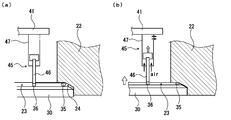
- FIG. A is a fragmentary sectional view which shows schematically the state in which an air cylinder exists in a non-operating state.
- B is a partial sectional view schematically showing a state in which the air cylinder is in an operating state. It is a figure which shows the outline of a structure in an example of the conventional theater space.
- FIG. 1 is a diagram showing an outline of a configuration in an example of a theater space using a projector device for a digital cinema movie theater of the present invention.
- a projector device (hereinafter also simply referred to as “projector device”) 10 for a digital cinema movie theater according to the present invention is a housing in which a projector for digital cinema (hereinafter also referred to as “digital projector”) 11 forms a sealed space. It is configured to be installed inside the body 20.
- the outer surface of the upper wall of the housing 20 is fixed to the ceiling surface C behind the spectator seat with respect to the screen S and installed in a separate room from the theater space Sr.
- the projector apparatus 10 may be fixed and installed in a state where a part of the housing 20 is embedded in the ceiling.
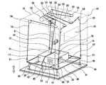
- FIG. 2 is a perspective view showing a schematic configuration of an example of a projector apparatus for a digital cinema movie theater according to the present invention.
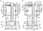
- FIG. 3 is an explanatory diagram schematically showing a state in which the digital cinema projector in the projector apparatus shown in FIG. 2 is housed in a housing.
- (A) is the fragmentary sectional view seen from the front direction
- (b) is the fragmentary sectional view seen from the left side surface direction.
- FIG. 4 is an explanatory diagram schematically showing a state in which the digital cinema projector in the projector apparatus shown in FIG. 2 is lowered from the housing.
- (A) is the fragmentary sectional view seen from the front direction
- (b) is the fragmentary sectional view seen from the left side direction.
- FIG. 3 is an explanatory diagram schematically showing a state in which the digital cinema projector in the projector apparatus shown in FIG. 2 is housed in a housing.
- (A) is the fragmentary sectional view seen from the front direction
- the projector device 10 includes a housing 20 whose bottom surface is configured to be openable and closable.
- the housing 20 has an upper opening 28 that opens upward in a substantially central portion of the upper wall, and a box-shaped housing main body 21 that has a lower opening 23 that opens downward in the central portion of the bottom wall 22.
- the lid body (cover plate) 30 opens and closes the lower opening 23 of the housing body 21.
- a projection opening 26 is formed in the front wall of the housing body 21.
- the projection opening 26 is airtightly closed by, for example, a glass plate-like window member 27, whereby the projection window 25 is formed. Is formed.
- the lower opening 23 of the housing main body 21 is configured by a through hole having a rectangular opening shape, and a lid body receiving portion to which the lid body 30 is received and attached to the lower surface side opening edge of the through hole.
- a mounting portion 24 is formed.
- the lid body receiving / mounting portion 24 is formed by a recess having a quadrangular frustum-shaped space portion and a quadrangular columnar space portion continuous therewith.
- the lid body 30 has an overall flat plate shape that fits the lid body receiving / mounting portion 24 in the housing body 21, and the outer peripheral edge portion on the upper surface is formed in a tapered shape.
- a rectangular frame-like airtight cushioning member 35 extends over the entire circumference in the circumferential direction of the lid 30 on the outer peripheral edge portion on the upper surface of the lid 30, specifically, on the flat surface portion on the inner side of the tapered surface. It is arranged. Then, the airtight buffer member 35 is elastically crushed by the flat surface of the lid body receiving / mounting portion 24 in the housing body 21 and the upper surface of the lid body 30, thereby forming an airtight structure of the housing 20.
- the airtight buffer member 35 is made of an elastic body having sound insulation or sound absorption.
- a preferable elastic material is a rubber material.
- sponge rubber such as chloroprene sponge, silicone sponge, fluorine rubber sponge, urethane sponge, PVC sponge, or chloroprene rubber, silicone rubber, ethylene / propylene / Solid rubber such as diene rubber (EPDM) can be used.
- EPDM diene rubber
- the wall in the housing 20, specifically, the wall in the housing body 21 and the lid body 30 are formed by a sound insulation panel.
- a sound insulation panel for example, a structure in which a sound insulation material or a sound absorbing material is filled in a space (hollow part) between two plate members arranged to face each other with a certain interval is used.
- the wall in the housing body 21 is constituted by a sound insulation panel in which, for example, a space (hollow portion) between two plate-like gypsum boards is filled with a sound insulation material or a sound absorption material.
- the lid body 30 is constituted by a sound insulation panel in which, for example, a space (hollow portion) between two steel plates is filled with a sound insulation material or a sound absorption material.
- plate materials in the sound insulation panel which comprises the cover body 30 to be the state which the steel plate shape
- the sound absorbing material or the sound insulating material include rock wool and glass wool.
- the sound insulation panel constituting the housing body 21 and the lid body 30 is configured such that the sound absorbing material is provided on the outer surface exposed to the theater space Sr.
- the sound absorbing material on the outer surface exposed to the theater space Sr is covered with the same interior cloth as the wall and ceiling surface C of the theater space Sr.
- the thickness of the wall in the housing main body 21 is, for example, 200 to 250 mm including the layer of the sound absorbing material on the outer surface, and the thickness of the lid 30 in the housing main body 21 is the sound absorbing material on the outer surface. Including up to this layer, it is, for example, 70 to 100 mm.
- the gantry 40 in this example includes a frame-like gantry frame 41 having a planar rectangular shape, and each of the pair of frame portions 42, 42 extending in the front-rear direction of the gantry frame 41 includes a plurality of, for example, one frame portion 42. It is supported from below by three (6 in total) air cylinders 45.
- the air cylinder 45 is described with reference to FIGS. 7A and 7B, the piston rod 46 slides in the vertical direction with respect to the cylindrical cylinder tube 47 at positions spaced apart from each other at equal intervals in the front-rear direction.
- the upper end of the cylinder tube 47 is fixed to the lower surface of the gantry frame 41, and the lower end of the piston rod 46 is fixed to the upper surface of the lid 30 by the fixing bracket 36.
- the digital projector 11 is supported on the gantry 40 so as to be displaceable (position adjustment is possible), and is fixed by, for example, a belt-like fixing member 43.
- the digital projector 11 is installed at a position separated by, for example, 300 mm or more from each wall surface of the housing 20, whereby a cooling airflow passage F is formed around the digital projector 11. With such a configuration, an excessive temperature rise of the digital projector 11 can be reliably prevented, and the digital projector 11 can be operated normally.
- the digital projector 11 includes, for example, a light source device 15 including a xenon discharge lamp, a so-called video engine 16, a power supply device 17, and a cooling mechanism in an outer casing.
- Reference numeral 12 denotes a projection lens.
- the video engine 16 includes, for example, a color filter, an image element, an appropriate optical lens, and the like.
- the cooling mechanism cools the xenon discharge lamp and other components by cooling air indicated by white arrows in FIG.
- This cooling mechanism includes an air supply fan 18 a for lamp cooling, an air supply fan 18 b for cooling other components, and an exhaust fan 19.
- FIG. 1 is an air supply fan 18 a for lamp cooling, an air supply fan 18 b for cooling other components, and an exhaust fan 19.
- reference numeral 13 denotes a cooling wind introduction opening formed on each of the back surface and both side surfaces of the outer casing of the digital projector 11, for example, an opening such as a slit.
- Reference numeral 14 denotes an exhaust opening formed on the upper surface of the outer casing of the digital projector 11.
- the rated power consumption is 2 to 6 kW
- the sealed pressure of xenon gas (normal temperature conversion) is 1 MPa or more, for example, 1 to 2 MPa
- the tube wall load is 30 W. / Cm 2 or more, for example, 30 to 40 W / cm 2 .
- the supply and exhaust amount of each cooling fan (18a, 18b, 19) is adjusted in accordance with the internal temperature state.
- the exhaust fan 19 is required to have a capacity of 18 m 3 / min or more as an exhaust amount.
- the projector device 10 is configured so that the digital projector 11 can be lowered from the inside of the housing body 21 by an elevating system that is provided inside the housing 20 and supports the digital projector 11 so as to be movable up and down.
- the hatched arrows in FIGS. 1 and 2 indicate the ascending / descending direction of the digital projector 11).
- the lifting system include a system in which the digital projector 11 is suspended by a conventional pantograph type lifting system, and a system in which the digital projector 11 is suspended by a wire as will be described in detail below.
- the elevating system 50 in this example is configured by a hoisting device. Specifically, each of the hanging tool 51 provided at the four corner positions on the upper surface of the gantry frame 41 and the hanging tool 51 provided on the fixing member 43 and positioned substantially at the center of the upper surface of the digital projector 11.
- the digital projector 11 is suspended and supported by a plurality of wires 55 with one end fixed, in this example, five wires 55.
- the hanging tool 51 is, for example, a screw-in type, and is configured such that the length of the wire 55 can be adjusted so as to be lifted and lowered in a state where the lid body 30 is maintained in a horizontal posture.
- Each wire 55 is stretched by a plurality of guide sheaves (groove wheels) 54, and the other end is fixed to a common wire drum 52.
- the wire drum 52 is disposed in a posture in which the rotation shaft extends in the horizontal direction, and is driven to rotate by a winding motor 53. Since the wire drum 52 and the winding motor 53 are common to the wires 55, the digital projector 11 can be reliably maintained in an appropriate posture, that is, horizontally when the digital projector 11 is moved up and down.
- the projector is provided with a position restricting means for restricting the position or posture of the digital projector 11 relative to the housing body 21 when the digital projector 11 is moved up and down.
- a position restricting means constituted by a guide rod 61 provided in the frame 41 and extending in the vertical direction and a pair of guide rollers 62 for guiding the guide rod 61 is provided. It is configured.
- the guide rod 61 is formed in a pointed shape (conical shape) having a smaller diameter as the upper end portion is directed upward.
- the guide rod 61 is provided at two diagonal positions on the upper surface of the gantry frame 41.
- the pair of guide rollers 62 are provided to be fixed to the casing main body 21 in such a manner that the rotation shaft extends in the horizontal direction at a position sandwiching a cylindrical guide rod moving path extending in the vertical direction.
- Each guide roller 62 has a guide groove 64 formed on the circumferential surface of the roller base 63, and a rod guide space R is formed by the guide grooves 64 of the pair of guide rollers 62.
- the rod guide space R is positioned in a state where the rotation axes of the guide rollers 62 are displaced in the vertical direction so that the rod guide space R has a shape that matches the outer contour shape of the guide rod 61 in plan view.
- the position regulating means is not limited to the one using the guide rod and the guide roller as long as it can regulate the position of the lid with respect to the housing during the raising / lowering operation of the digital projector.
- one end portion of the exhaust duct 70 extending in the vertical direction is connected to the exhaust opening portion 14 formed on the upper surface of the outer casing of the digital projector 11, and is shown in FIG.
- the exhaust duct 70 is led out of the housing 20 through the upper opening 28 formed in the upper wall of the housing body 21.
- the other end of the exhaust duct 70 is connected to an exhaust fan 71 disposed behind the ceiling.
- the exhaust passage Ep extending outside the apparatus is formed in a state of being isolated from the theater section Sr, and is shown by hot air or hot air related to the exhaust of the digital projector 11 (in FIG. 1, it is indicated by a solid arrow).
- the cooling air supply fan 75 and the exhaust fan 71 disposed on the back of the ceiling have a function of supplying cooling air and a function of discharging hot air related to exhaust at a flow rate of, for example, 18 m 3 / min or more.
- the exhaust duct 70 is formed of, for example, a bellows that can be expanded and contracted in the up-and-down direction of the digital projector 11, and is expanded and contracted as the digital projector 11 moves up and down.
- the digital projector 11 is normally housed inside the housing 20 and isolated from the theater space Sr, as described above. In operation, the discharge lamp and other components are cooled by the cooling air.
- the digital projector 11 is lowered from the inside of the housing 20 by the elevating system 50 as shown in FIGS. That is, when the winding motor 53 is driven in reverse, for example, the wire drum 52 is rotated, the wires 55 are fed out with the same feeding amount, and the exhaust duct 70 is extended so that the lid 30 becomes horizontal.
- the digital projector 11 is lowered to a predetermined position (for example, a position about 80 cm from the floor surface) with respect to the floor surface.
- the feeding speed of the wire 55 can be set as appropriate within a range of, for example, 7 m / min or less, and may be constant or changed.
- the operation of the take-up motor 53 is controlled so that the feed speed is lowered (eventually becomes 0 m / min) as it approaches the floor surface. can do.
- the air cylinder 45 is in an operating state when compressed air is supplied in a state in which the digital projector 11 is housed in the housing 20, but when the digital projector 11 is lowered.
- the piston rod 46 is placed at a position below the cylinder tube 47 by stopping the supply of compressed air.
- the wire drum 52 is rotated by, for example, normal winding driving of the winding motor 53, and the wires 55 are the same.
- the digital projector 11 is raised in a state in which the exhaust duct 70 is shortened and the posture in which the lid 30 is leveled is maintained while being wound up by the winding amount.
- the winding speed of the wire 55 can be appropriately set within a range of, for example, 7 m / min or less, and may be constant or changed.
- the take-up motor 53 is set so that the take-up speed is reduced (finally 0 m / min) as it approaches the casing body 21.
- the operation can also be controlled.
- each guide rod 61 is in a rod guide space R formed by a corresponding pair of guide rollers 62.
- the guide rod 61 is guided by the guide roller 62 after being inserted. Thereby, the position or attitude of the digital projector 11 with respect to the housing body 21 is regulated.
- each wire 55 is wound by a predetermined winding amount, and the lid 30 is attached to the lid body receiving / mounting portion 24 in the housing body 21 via the airtight buffer member 35.
- the drive of the winding motor 53 is stopped.
- vibration when the lid 30 is housed in the receiving mounting portion 24 of the housing body 21 is reduced by the airtight buffer member 35.
- the drive control of the winding motor 53 can be performed by, for example, an overwinding prevention means (not shown) such as a limit switch or a sensor.
- the projector device 10 having the above configuration, basically, all the components such as the digital projector 11 and the lifting system 50 are accommodated in the housing 20, so that the beauty of the theater space Sr can be improved. It can be installed in the theater space Sr without any damage, and the theater space Sr can be used effectively. Moreover, since the projector for digital cinema is installed in a sealed casing, noise such as the operating sound of the cooling mechanism emitted in the theater space can be reduced as much as possible, and cooling air and exhaust can be reduced. Therefore, it is possible to avoid the discharge of hot air or hot air in the theater space, and to provide a more comfortable theater space.
- the following effects are acquired.
- (1) When performing the maintenance work it is only necessary to lower the digital projector 11 by the lifting system 50 using the wire 55, so that it is not necessary to work at a high place near the ceiling of the theater space Sr, and it is safe and reliable. Work can be done.
- the digital projector 11 is suspended and supported by the wire 55, the operator can access from the entire circumference of the digital projector 11, so that maintenance work can be easily and reliably performed. High workability can be obtained.
- the housing 20 itself can be configured to have high sound insulating properties and sound absorbing properties. Further, the operation of the air cylinder 45 maintains the state in which the lid 30 is pressed against the housing main body 21 via the airtight cushioning member 35, thereby forming the airtight structure of the housing 20.
- the body 20 has higher sound insulation and sound absorption.
- noise such as operation noise of the cooling mechanism of the digital projector 11 (the air supply fan 18a for cooling the lamp, the air supply fan 18b for cooling other components, and the exhaust fan 19) Since the casing 20 is configured so that its lower surface can be opened and closed, the noise generated from the projector device 10 into the theater space Sr is as much as possible. Can be reduced to a small size. Specifically, for example, when the sound pressure (level) of the sound emitted from the digital projector 11 itself is about 70 dBA, according to the projector device 10 having the above configuration, the sound emitted from the projector device 10 measured by the same method. The sound pressure (level) of the generated sound can be reduced to about 30 dBA.
- the airtightness of the housing 20 does not deteriorate due to the influence of the weight of the digital projector 11 and the like, for example, the operation sound of the cooling mechanism emitted from the digital projector 11 is reliably prevented from leaking into the theater space Sr. can do.
- the vertical position of the digital projector 11 in the housing 20 can be finely adjusted by operating the air cylinder 45. For this reason, it is possible to avoid the positional deviation of the position of the projection lens 12 of the digital projector 11 from the position of the projection window 25 in the housing 20 due to the lifting / lowering operation of the digital projector 11 or the weight of the digital projector 11. This eliminates the need to readjust the optical system.
- the cooling air for cooling the digital cinema projector supplied from the outside of the apparatus through the air supply passage is circulated through the cooling air flow passage formed inside the housing, thereby cooling the internal space of the housing.
- the projector for digital cinema is cooled from the outer surface side. Furthermore, since the digital cinema projector is cooled by introducing the cooling air into the digital cinema projector, an excessive temperature rise of the digital projector can be surely prevented, and the digital cinema projector can be It can be operated normally.
- the housing is not limited to a configuration in which the opening of the housing body is opened and closed with a lid.
- the number of wires for supporting the digital projector in a suspended manner, the fixed positions of the wires, the number of air cylinders, and other specific configurations can be changed as appropriate.
- the position restricting means is not limited to the one using the guide rod and the guide roller as long as it can restrict the position of the lid relative to the housing during the raising / lowering operation of the digital projector.
- the two airtight cushioning members may be arranged on the surface of the lid so as to extend in parallel with each other at a predetermined interval to form a double seal structure.
- the airtight buffer member may be configured to be provided in the housing body.
Landscapes
- Engineering & Computer Science (AREA)
- General Engineering & Computer Science (AREA)
- Mechanical Engineering (AREA)
- Physics & Mathematics (AREA)
- General Physics & Mathematics (AREA)
- Projection Apparatus (AREA)
Abstract
本発明は、劇場空間を美観を損なうことなく有効に利用することができると共に、より快適な劇場空間を提供することができ、しかも、メンテナンス作業を容易にかつ確実に行うことのできるデジタルシネマ映画館用のプロジェクタ装置を提供することを目的とする。 このプロジェクタ装置は、スクリーンに対向する正面に映写窓が形成された筐体本体における下方に開口する開口部が、筐体本体と共に密閉空間を形成する蓋体により開閉される筐体と、筐体の内部に設置されたデジタルシネマ用プロジェクタと、デジタルシネマ用プロジェクタをワイヤにより吊下支持する昇降システムとを備えてなり、デジタルシネマ用プロジェクタが、昇降システムによって、筐体から下方に降下可能に構成されている。
Description
本発明は、例えば、シネマコンプレックスによるデジタルシネマ映画館用のプロジェクタ装置に関する。
現在、映画産業にあっては、いわゆる「シネマコンプレックス」と呼ばれる複合型映画館のスクリーン数が増加する傾向にある。
近年においては、映画産業は、世界的にフィルムからデジタルへの大きな変革期を迎えており、映画のデジタル化が急速に進み、高精細な映像が提供されるようになってきている。
近年においては、映画産業は、世界的にフィルムからデジタルへの大きな変革期を迎えており、映画のデジタル化が急速に進み、高精細な映像が提供されるようになってきている。
シネマコンプレックスによるデジタルシネマにおいては、複数のデジタルシネマ用プロジェクタを用いて互いに異なるものの同時上映が可能であり、また、デジタルシネマ用プロジェクタの操作を一元的に管理することが可能である。すなわち、映写フィルムによってビデオ情報(映画)を配給する劇場においては、図8に示すように、映画の上映中に、上映室(劇場空間Sr)とは別に隔離して設置された映写室Prに、映写機80を操作する映写技師が待機する必要があった。この理由は、映画の上映中、映写機80の状態やスクリーンSを常に確認する必要があるためである。然るに、シネマコンプレックスによるデジタルシネマにおいては、例えばLANなどのネットワークを利用して、各デジタルシネマ用プロジェクタに映像信号を送ることによりデジタルシネマが提供される。このため、映画の上映中に映写技師が現場で作業する必要はない。また、デジタルシネマにおいては、十分な広さ(作業用スペース)が確保された映写室を設置する必要がないので、狭小面積の劇場であっても、来場者にとっての快適性を損なうことなく、劇場空間を有効に利用することができる。
一方、こうしたハードウェアの変化に伴い、劇場の構造自体も大きく様変わりを遂げることになり、デジタルシネマ用プロジェクタを上映室内に設置することが検討されている(例えば特許文献1参照)。
而して、一般に、デジタルシネマ用プロジェクタは、大型のスクリーンに映像を投影するべく、光源としては、例えば、高入力の輝度を高めたキセノンショートアーク型の放電ランプが使用されている。このため、放電ランプの冷却機構等も一体化されて設けられた構成とされており、デジタルシネマ用プロジェクタ自体が非常に大きなものとなる。従って、特許文献1のように、デジタルシネマ用プロジェクタを床面に設置したのでは、例えば観客席の後方側に機器設置用の十分な広さの空間が必要となる。
また、デジタルシネマ用プロジェクタにおいては、ランプ交換などのメンテナンス作業を例えば定期的に行うことが必要とされることから、デジタルシネマ用プロジェクタを上映室内に設置するにあたり、メンテンナンス性(作業性)などを考慮した空間設計が必要となると共に、放電ランプ等の冷却にかかる騒音や排気を考慮する必要がある。
而して、一般に、デジタルシネマ用プロジェクタは、大型のスクリーンに映像を投影するべく、光源としては、例えば、高入力の輝度を高めたキセノンショートアーク型の放電ランプが使用されている。このため、放電ランプの冷却機構等も一体化されて設けられた構成とされており、デジタルシネマ用プロジェクタ自体が非常に大きなものとなる。従って、特許文献1のように、デジタルシネマ用プロジェクタを床面に設置したのでは、例えば観客席の後方側に機器設置用の十分な広さの空間が必要となる。
また、デジタルシネマ用プロジェクタにおいては、ランプ交換などのメンテナンス作業を例えば定期的に行うことが必要とされることから、デジタルシネマ用プロジェクタを上映室内に設置するにあたり、メンテンナンス性(作業性)などを考慮した空間設計が必要となると共に、放電ランプ等の冷却にかかる騒音や排気を考慮する必要がある。
このような問題に対して、劇場空間の有効利用性を十分に活かすべく、例えば特許文献2および特許文献3には、プロジェクタを天井から吊り下げて支持するプロジェクタ用のリフトシステムが開示されている。このような構造によれば、劇場の空間において十分な広さの来場者用スペースを確保することができ、より快適な空間設計が可能になることが期待される。
しかしながら、デジタルシネマ用プロジェクタを単に天井から吊り下げて支持する構造では、劇場の美観を損なわせてしまうという問題がある。
また、デジタルシネマ用プロジェクタの冷却風の排気が劇場空間内に広がるため、デジタルシネマ用プロジェクタの近くの客席では当該排気による熱風で不快に感じるといった問題や、冷却機構の動作音などが劇場空間内に漏れ出てしまうため、来場者がデジタルシネマの高精細な映像による臨場感を十分に楽しむことができなくなり、快適性が著しく損なわれるといった問題がある。
しかしながら、デジタルシネマ用プロジェクタを単に天井から吊り下げて支持する構造では、劇場の美観を損なわせてしまうという問題がある。
また、デジタルシネマ用プロジェクタの冷却風の排気が劇場空間内に広がるため、デジタルシネマ用プロジェクタの近くの客席では当該排気による熱風で不快に感じるといった問題や、冷却機構の動作音などが劇場空間内に漏れ出てしまうため、来場者がデジタルシネマの高精細な映像による臨場感を十分に楽しむことができなくなり、快適性が著しく損なわれるといった問題がある。
本発明は、以上のような事情に基づいてなされたものであって、その目的は、劇場空間の美観を損なうことなく、劇場空間を有効に利用することができ、しかも、デジタルシネマ用プロジェクタからの排気や騒音に係る問題を解消することができてより快適な劇場空間を提供することのできるデジタルシネマ映画館用のプロジェクタ装置を提供することである。
また、本発明の他の目的は、デジタルシネマ用プロジェクタのメンテナンス作業を容易にかつ確実に行うことのできるデジタルシネマ映画館用のプロジェクタ装置を提供することである。
また、本発明の他の目的は、デジタルシネマ用プロジェクタのメンテナンス作業を容易にかつ確実に行うことのできるデジタルシネマ映画館用のプロジェクタ装置を提供することである。
本発明のデジタルシネマ映画館用のプロジェクタ装置は、劇場空間の天井部に固定された筐体と、当該筐体の内部に設置されたデジタルシネマ用プロジェクタと、当該デジタルシネマ用プロジェクタをワイヤにより吊下支持する昇降システムとを備えてなり、
前記筐体は、スクリーンに対向する正面に映写窓が形成された、下方に開口する開口部を有する筐体本体と、当該筐体本体における開口部を開閉し、筐体本体と共に密閉空間を形成する蓋体とにより構成されており、
前記デジタルシネマ用プロジェクタが、前記昇降システムによって、前記筐体から下方に降下可能に構成されていることを特徴とする。
前記筐体は、スクリーンに対向する正面に映写窓が形成された、下方に開口する開口部を有する筐体本体と、当該筐体本体における開口部を開閉し、筐体本体と共に密閉空間を形成する蓋体とにより構成されており、
前記デジタルシネマ用プロジェクタが、前記昇降システムによって、前記筐体から下方に降下可能に構成されていることを特徴とする。
本発明のデジタルシネマ映画館用のプロジェクタ装置においては、前記筐体の開口部を開閉する蓋体上には、前記デジタルシネマ用プロジェクタを支持する架台がエアシリンダを介して固定され、当該架台に前記ワイヤが固定されて当該デジタルシネマ用プロジェクタが吊下支持されており、
前記エアシリンダは、加圧空気が供給されることにより前記蓋体の前記筐体本体に対する押圧状態が保持されるよう作動するものであることが好ましい。
前記エアシリンダは、加圧空気が供給されることにより前記蓋体の前記筐体本体に対する押圧状態が保持されるよう作動するものであることが好ましい。
このような構成のデジタルシネマ映画館用のプロジェクタ装置においては、前記デジタルシネマ用プロジェクタの昇降動作時において、当該デジタルシネマ用プロジェクタの前記筐体本体に対する位置を規制する位置規制手段を備えており、
当該位置規制手段は、前記架台に設けられた上下方向に延びる案内ロッドと、前記筐体本体に対して回転軸が固定されて設けられた、当該案内ロッドを案内する一対の案内ローラとにより構成されていることが好ましい。
当該位置規制手段は、前記架台に設けられた上下方向に延びる案内ロッドと、前記筐体本体に対して回転軸が固定されて設けられた、当該案内ロッドを案内する一対の案内ローラとにより構成されていることが好ましい。
本発明のデジタルシネマ映画館用のプロジェクタ装置は、劇場空間の天井部に固定された、内部に密閉空間を形成する筐体と、当該筐体の内部に設置された、冷却機構を備えたデジタルシネマ用プロジェクタと、当該デジタルシネマ用プロジェクタをワイヤにより吊下支持する昇降システムとを備えており、
前記筐体における壁が遮音パネルにより形成されており、
前記筐体は、下方に開口する開口部を有する筐体本体と、当該筐体本体における開口部を開閉する蓋体とにより構成されており、当該蓋体上には、前記デジタルシネマ用プロジェクタを支持する架台がエアシリンダを介して固定され、当該架台に前記ワイヤが固定されて当該デジタルシネマ用プロジェクタが吊下支持されており、
前記エアシリンダは、加圧空気が供給されることにより前記蓋体の前記筐体本体に対する押圧状態が保持されるよう作動するものであることを特徴とする。
前記筐体における壁が遮音パネルにより形成されており、
前記筐体は、下方に開口する開口部を有する筐体本体と、当該筐体本体における開口部を開閉する蓋体とにより構成されており、当該蓋体上には、前記デジタルシネマ用プロジェクタを支持する架台がエアシリンダを介して固定され、当該架台に前記ワイヤが固定されて当該デジタルシネマ用プロジェクタが吊下支持されており、
前記エアシリンダは、加圧空気が供給されることにより前記蓋体の前記筐体本体に対する押圧状態が保持されるよう作動するものであることを特徴とする。
また、このような構成のデジタルシネマ映画館用のプロジェクタ装置においては、前記蓋体および前記筐体本体のいずれか一方に、弾性体よりなる気密性緩衝部材が、当該蓋体および当該筐体本体との間に介在する状態で、設けられた構成とされていることが好ましい。
本発明のデジタルシネマ映画館用のプロジェクタ装置は、劇場空間の天井部に上壁部が固定された、内部に密閉空間を形成する筐体と、当該筐体の内部に設置された、冷却機構を備えたデジタルシネマ用プロジェクタとを備えてなり、
前記デジタルシネマ用プロジェクタを冷却する冷却風の給気路と排気路が、前記劇場空間と隔離された状態で、前記筐体の上壁を介して装置外部に延びるよう形成されており、
前記排気路は、前記デジタルシネマ用プロジェクタにおける排気用開口部に一端部が接続された排気用ダクトが、前記筐体の上壁に形成された上方開口部を介して、装置外部に導出されて形成されており、
前記筐体は、下面が開閉可能に構成され、内部に前記デジタルシネマ用プロジェクタを昇降可能に支持する昇降システムを備えており、
前記排気用ダクトが、前記デジタルシネマ用プロジェクタの昇降方向に伸縮自在なベローズにより構成されていることを特徴とする。
前記デジタルシネマ用プロジェクタを冷却する冷却風の給気路と排気路が、前記劇場空間と隔離された状態で、前記筐体の上壁を介して装置外部に延びるよう形成されており、
前記排気路は、前記デジタルシネマ用プロジェクタにおける排気用開口部に一端部が接続された排気用ダクトが、前記筐体の上壁に形成された上方開口部を介して、装置外部に導出されて形成されており、
前記筐体は、下面が開閉可能に構成され、内部に前記デジタルシネマ用プロジェクタを昇降可能に支持する昇降システムを備えており、
前記排気用ダクトが、前記デジタルシネマ用プロジェクタの昇降方向に伸縮自在なベローズにより構成されていることを特徴とする。
このような構成のデジタルシネマ映画館用のプロジェクタ装置においては、前記筐体は、前記上方開口部および下方に開口する下方開口部を有する筐体本体と、当該筐体本体における下方開口部を開閉する蓋体とにより構成されており、
当該蓋体および当該筐体本体のいずれか一方に、弾性体よりなる気密性緩衝部材が、当該蓋体および当該筐体本体との間に介在する状態で、設けられた構成とされていることが好ましい。
当該蓋体および当該筐体本体のいずれか一方に、弾性体よりなる気密性緩衝部材が、当該蓋体および当該筐体本体との間に介在する状態で、設けられた構成とされていることが好ましい。
本発明のデジタルシネマ映画館用のプロジェクタ装置は、劇場空間の天井部に上壁部が固定された、内部に密閉空間を形成する筐体と、当該筐体の内部に設置された、冷却機構を備えたデジタルシネマ用プロジェクタとを備えてなり、
前記デジタルシネマ用プロジェクタを冷却する冷却風の給気路と排気路が、前記劇場空間と隔離された状態で、前記筐体の上壁を介して装置外部に延びるよう形成されており、
前記筐体の内部には、前記デジタルシネマ用プロジェクタを冷却する冷却風が流通される冷却風流通路が形成されていることを特徴とする。
前記デジタルシネマ用プロジェクタを冷却する冷却風の給気路と排気路が、前記劇場空間と隔離された状態で、前記筐体の上壁を介して装置外部に延びるよう形成されており、
前記筐体の内部には、前記デジタルシネマ用プロジェクタを冷却する冷却風が流通される冷却風流通路が形成されていることを特徴とする。
本発明のデジタルシネマ映画館用のプロジェクタ装置においては、前記排気路には排気用ファンが設けられており、当該排気用ファンは、前記劇場空間の天井裏に配設された構成とされていることが好ましい。
このような構成のデジタルシネマ映画館用のプロジェクタ装置においては、前記給気路には冷却風供給用ファンが設けられており、当該冷却風供給用ファンは、前記劇場空間の天井裏に配設された構成とされていることが好ましい。
本発明の請求項1に係るデジタルシネマ映画館用のプロジェクタ装置によれば、基本的には、デジタルシネマ用プロジェクタおよび昇降システムなどの全ての構成要素が筐体内に収容されているので、劇場空間の美観を損なうことなく、劇場空間内に設置することができて劇場空間を有効に利用することができる。しかも、デジタルシネマ用プロジェクタが密閉された筐体内に設置されているので、劇場空間内に発せられる冷却機構の動作音などの騒音を可及的に小さく低減することができると共に、冷却風および排気に係る熱風ないしは温風が劇場空間内に排出されることを回避することができ、より快適な劇場空間を提供することができる。
また、メンテナンス作業を行うに際しては、デジタルシネマ用プロジェクタをワイヤによる昇降システムによって降下させればよいので、劇場空間の天井付近の高所において作業を行う必要がなくなり、安全かつ確実に所期の作業を行うことができる。
しかも、デジタルシネマ用プロジェクタがワイヤによって吊下支持されていることにより、作業者は、デジタルシネマ用プロジェクタの全周方向からアクセスすることができるので、メンテナンス作業を容易にかつ確実に行うことができて高い作業性を得ることができる。
また、メンテナンス作業を行うに際しては、デジタルシネマ用プロジェクタをワイヤによる昇降システムによって降下させればよいので、劇場空間の天井付近の高所において作業を行う必要がなくなり、安全かつ確実に所期の作業を行うことができる。
しかも、デジタルシネマ用プロジェクタがワイヤによって吊下支持されていることにより、作業者は、デジタルシネマ用プロジェクタの全周方向からアクセスすることができるので、メンテナンス作業を容易にかつ確実に行うことができて高い作業性を得ることができる。
請求項2に係るデジタルシネマ映画館用のプロジェクタ装置によれば、筐体内におけるデジタルシネマ用プロジェクタの上下方向の位置をエアシリンダを作動させることによって微調整することができるので、デジタルシネマ用プロジェクタの昇降動作によって、あるいは、デジタルシネマ用プロジェクタの自重によって、デジタルシネマ用プロジェクタの投影レンズの位置の、筐体における映写窓の位置に対する位置ずれが生ずることを回避することができ、光学系を再調整するなどの作業が不要となる。
さらにまた、エアシリンダによって蓋体の筐体本体に対する押圧状態が保持されるので、例えばデジタルシネマ用プロジェクタの自重の影響などによって、筐体の気密性が低下することがなく、デジタルシネマ用プロジェクタから発せられる例えば冷却機構の動作音などの騒音が劇場空間に漏れることを一層確実に防止することができる。
さらにまた、エアシリンダによって蓋体の筐体本体に対する押圧状態が保持されるので、例えばデジタルシネマ用プロジェクタの自重の影響などによって、筐体の気密性が低下することがなく、デジタルシネマ用プロジェクタから発せられる例えば冷却機構の動作音などの騒音が劇場空間に漏れることを一層確実に防止することができる。
請求項3に係るデジタルシネマ映画館用のプロジェクタ装置によれば、デジタルシネマ用プロジェクタの昇降動作時において、案内ロッドと案内ローラにより構成された位置規制手段によって、デジタルシネマ用プロジェクタの、筐体本体に対する位置が規制されるので、デジタルシネマ用プロジェクタの昇降動作時に多少の揺れが加わっても、ワイヤが撓んだり、蓋体の水平性が著しく崩れたりすることがなく、デジタルシネマ用プロジェクタの昇降動作を安全にかつ確実に行うことができる。
請求項4に係るデジタルシネマ映画館用のプロジェクタ装置によれば、劇場空間を有効に利用することができ、しかも、デジタルシネマ用プロジェクタからの排気や騒音に係る問題を解消することができてより快適な劇場空間を提供することができるという効果、並びに、デジタルシネマ用プロジェクタのメンテナンス作業を容易にかつ確実に行うことのできるという効果が得られる。しかも、デジタルシネマ用プロジェクタの冷却機構の動作音などが、筐体における壁を構成する遮音パネルによって遮蔽されるので、プロジェクタ装置から劇場空間内に発せられる騒音を可及的に小さく低減することができる。
さらにまた、エアシリンダによって蓋体の筐体本体に対する押圧状態が保持されるので、例えばデジタルシネマ用プロジェクタの自重の影響などによって、筐体の気密性が低下することがなく、デジタルシネマ用プロジェクタから発せられる例えば冷却機構の動作音などの騒音が劇場空間に漏れることを一層確実に防止することができる。
さらにまた、エアシリンダによって蓋体の筐体本体に対する押圧状態が保持されるので、例えばデジタルシネマ用プロジェクタの自重の影響などによって、筐体の気密性が低下することがなく、デジタルシネマ用プロジェクタから発せられる例えば冷却機構の動作音などの騒音が劇場空間に漏れることを一層確実に防止することができる。
請求項5に係るデジタルシネマ映画館用のプロジェクタ装置によれば、エアシリンダの作動によって気密性緩衝部材が筐体本体と蓋体とによって弾性的に圧潰されることにより筐体の気密構造(密閉構造)が形成される構成とされているので、筐体がその下面が開閉可能に構成されたものでありながら、デジタルシネマ用プロジェクタから発せられる音が蓋体と筐体本体との対接部(微小間隙)を介して劇場空間に漏れることを一層確実に防止することができる。
請求項6に係るデジタルシネマ映画館用のプロジェクタ装置によれば、劇場空間を有効に利用することができ、しかも、デジタルシネマ用プロジェクタからの排気や騒音に係る問題を解消することができてより快適な劇場空間を提供することができるという効果、並びに、デジタルシネマ用プロジェクタのメンテナンス作業を容易にかつ確実に行うことのできるという効果が得られる。しかも、各々劇場空間と隔離された状態で形成された給気路と排気路を介して、冷却風が装置外部からデジタルシネマ用プロジェクタに供給されると共に当該デジタルプロジェクタの排気に係る熱風が排出されるので、冷却風および排気に係る熱風ないしは温風が劇場空間内に排出されることを回避することができる。
さらにまた、ベローズにより構成された排気用ダクトによって、排気用ダクトがデジタルシネマ用プロジェクタに接続された状態を維持することができるので、デジタルシネマ用プロジェクタが降下された状態にあっても、デジタルシネマ用プロジェクタに対する冷却風の供給、排気を行うことができて、メンテンナンス作業後のデジタルシネマ用プロジェクタの動作確認を筐体内に収容することなく行うことができる。
さらにまた、ベローズにより構成された排気用ダクトによって、排気用ダクトがデジタルシネマ用プロジェクタに接続された状態を維持することができるので、デジタルシネマ用プロジェクタが降下された状態にあっても、デジタルシネマ用プロジェクタに対する冷却風の供給、排気を行うことができて、メンテンナンス作業後のデジタルシネマ用プロジェクタの動作確認を筐体内に収容することなく行うことができる。
請求項7に係るデジタルシネマ映画館用のプロジェクタ装置によれば、気密性緩衝部材が筐体本体と蓋体とによって弾性的に圧潰されることにより筐体の気密構造(密閉構造)が形成される構成とされているので、筐体がその下面が開閉可能に構成されたものでありながら、デジタルシネマ用プロジェクタから発せられる音が蓋体と筐体本体との対接部(微小間隙)を介して劇場空間に漏れることを一層確実に防止することができる。
請求項8に係るデジタルシネマ映画館用のプロジェクタ装置によれば、劇場空間を有効に利用することができ、しかも、デジタルシネマ用プロジェクタからの排気や騒音に係る問題を解消することができてより快適な劇場空間を提供することができるという効果、並びに、デジタルシネマ用プロジェクタのメンテナンス作業を容易にかつ確実に行うことのできるという効果が得られる。しかも、装置外部から給気路を介して供給されるデジタルシネマ用プロジェクタを冷却する冷却風が、筐体内部において形成された冷却風流通路を流通されることによって、筐体の内部空間が冷却されると共にデジタルシネマ用プロジェクタがその外面側から冷却される。さらに、当該冷却風がデジタルシネマ用プロジェクタの内部に導入されることによって当該デジタルシネマ用プロジェクタが冷却されるので、デジタルプロジェクタの過度の温度上昇を確実に防止することができてデジタルシネマ用プロジェクタを正常に動作させることができる。
請求項9および請求項10に係るデジタルシネマ映画館用のプロジェクタ装置によれば、排気路に設けられた排気用ファンおよび給気路に設けられた冷却風供給用ファンが劇場空間の天井裏に配設されていることにより、排気用ファンおよび冷却風供給用ファンの動作音などの騒音が劇場空間に漏れることを一層確実に防止することができる。
以下、本発明の実施の形態について詳細に説明する。
図1は、本発明のデジタルシネマ映画館用のプロジェクタ装置を利用した劇場空間の一例における構成の概略を示す図である。
本発明のデジタルシネマ映画館用のプロジェクタ装置(以下、単に「プロジェクタ装置」ともいう。)10は、デジタルシネマ用プロジェクタ(以下、「デジタルプロジェクタ」ともいう。)11が、密閉空間を形成する筐体20の内部に設置されて構成されている。そして、劇場空間Srにおいて、例えば、筐体20の上壁の外面がスクリーンSに対して観客席の後方の天井面Cに固定されて設置され、劇場空間Srと別室に設置された映像信号(画像信号+音声信号)を送信するプレーヤ(図示せず)に、適宜の信号ケーブル(例えばLANケーブルなど)によって接続されて用いられる。なお、プロジェクタ装置10は、筐体20の一部が天井内に埋め込まれた状態で固定されて設置されていてもよい。
図1は、本発明のデジタルシネマ映画館用のプロジェクタ装置を利用した劇場空間の一例における構成の概略を示す図である。
本発明のデジタルシネマ映画館用のプロジェクタ装置(以下、単に「プロジェクタ装置」ともいう。)10は、デジタルシネマ用プロジェクタ(以下、「デジタルプロジェクタ」ともいう。)11が、密閉空間を形成する筐体20の内部に設置されて構成されている。そして、劇場空間Srにおいて、例えば、筐体20の上壁の外面がスクリーンSに対して観客席の後方の天井面Cに固定されて設置され、劇場空間Srと別室に設置された映像信号(画像信号+音声信号)を送信するプレーヤ(図示せず)に、適宜の信号ケーブル(例えばLANケーブルなど)によって接続されて用いられる。なお、プロジェクタ装置10は、筐体20の一部が天井内に埋め込まれた状態で固定されて設置されていてもよい。
図2は、本発明のデジタルシネマ映画館用のプロジェクタ装置の一例における構成の概略を示す斜視図である。図3は、図2に示すプロジェクタ装置におけるデジタルシネマ用プロジェクタが筐体内に収容された状態を概略的に示す説明図である。(a)は、正面方向から見た部分断面図、(b)は、左側面方向から見た部分断面図である。図4は、図2に示すプロジェクタ装置におけるデジタルシネマ用プロジェクタが筐体から降下された状態を概略的に示す説明図である。(a)は、正面方向から見た部分断面図であり、(b)は、左側面方向から見た部分断面図である。図2においては、筐体20の内側に設けられた構成部材を見やすくするために、便宜上、筐体本体21を透過した状態で示してあり、筐体本体21自体は二点鎖線で示してある。
このプロジェクタ装置10は、下面が開閉可能に構成された筐体20を備えている。筐体20は、上壁の略中央部に上方に開口する上方開口部28を有すると共に、底壁22の中央部に下方に開口する下方開口部23を有する箱型形状の筐体本体21と、この筐体本体21の下方開口部23を開閉する蓋体(カバー板)30とにより構成されている。
このプロジェクタ装置10は、下面が開閉可能に構成された筐体20を備えている。筐体20は、上壁の略中央部に上方に開口する上方開口部28を有すると共に、底壁22の中央部に下方に開口する下方開口部23を有する箱型形状の筐体本体21と、この筐体本体21の下方開口部23を開閉する蓋体(カバー板)30とにより構成されている。
筐体本体21の正面壁には、映写用開口部26が形成されており、当該映写用開口部26が例えばガラス製の板状の窓部材27により気密に閉塞され、これにより映写窓25が形成されている。
筐体本体21の下方開口部23は、開口形状が矩形状の貫通孔により構成されており、この貫通孔の下面側開口縁部には、蓋体30が受容されて装着される蓋体受容装着部24が形成されている。蓋体受容装着部24は、四角錐台状空間部とこれに連続する四角柱状空間部とを有する凹所により形成されている。
蓋体30は、筐体本体21における蓋体受容装着部24に適合する全体が平板状の形状を有し、上面における外周縁部がテーパ状に形成されている。
蓋体30の上面における外周縁部、具体的には、テーパ面より内方側の平坦面部分には、矩形枠状の気密性緩衝部材35が蓋体30の周方向の全周にわたって延びるよう配設されている。そして、筐体本体21における蓋体受容装着部24の平坦面および蓋体30の上面によって、気密性緩衝部材35が弾性的に圧潰されることにより筐体20の気密構造が形成される。
気密性緩衝部材35は、遮音性ないしは吸音性を有する弾性体により構成される。弾性体の材質として好ましいものはゴム材であり、具体的には、クロロプレンスポンジ、シリコーンスポンジ、フッ素ゴムスポンジ、ウレタンスポンジ、PVCスポンジなどのスポンジゴム、或いは、クロロプレンゴム、シリコーンゴム、エチレン・プロピレン・ジエンゴム(EPDM)などのソリッドゴムが挙げられる。
このように、筐体本体21における蓋体受容装着部24と蓋体30との対接面が単なる平坦面ではなく、いわば屈曲した平面により構成されていることにより、高い遮音性を得ることができる。
このように、筐体本体21における蓋体受容装着部24と蓋体30との対接面が単なる平坦面ではなく、いわば屈曲した平面により構成されていることにより、高い遮音性を得ることができる。
上記のプロジェクタ装置10においては、筐体20における壁、具体的には、筐体本体21における壁および蓋体30が遮音パネルにより形成されている。
遮音パネルとしては、例えば、一定の間隔をおいて互いに対向配置された2枚の板材の間の空間内(中空部)に、遮音材または吸音材が充填されて構成されたものが用いられる。
この例においては、筐体本体21における壁は、例えば2枚の板状の石膏ボード間の空間内(中空部)に、遮音材または吸音材が充填された遮音パネルによって構成されている。
また、蓋体30は、例えば2枚の鉄板間の空間内(中空部)に、遮音材または吸音材が充填された遮音パネルにより構成されている。なお、蓋体30を構成する遮音パネルにおける2枚の板材は、その周縁部分においてコの字型に成形された鋼板が溶接されて接合された状態とされているのがよい。このような遮音パネルによると、内部の遮音材または吸音材が密閉されることで、遮音性を一層高めた構造体となり、さらに、蓋体30自体の耐荷重性も高めることができる。
吸音材または遮音材としては、例えばロックウール、グラスウールなどを例示することができる。
遮音パネルとしては、例えば、一定の間隔をおいて互いに対向配置された2枚の板材の間の空間内(中空部)に、遮音材または吸音材が充填されて構成されたものが用いられる。
この例においては、筐体本体21における壁は、例えば2枚の板状の石膏ボード間の空間内(中空部)に、遮音材または吸音材が充填された遮音パネルによって構成されている。
また、蓋体30は、例えば2枚の鉄板間の空間内(中空部)に、遮音材または吸音材が充填された遮音パネルにより構成されている。なお、蓋体30を構成する遮音パネルにおける2枚の板材は、その周縁部分においてコの字型に成形された鋼板が溶接されて接合された状態とされているのがよい。このような遮音パネルによると、内部の遮音材または吸音材が密閉されることで、遮音性を一層高めた構造体となり、さらに、蓋体30自体の耐荷重性も高めることができる。
吸音材または遮音材としては、例えばロックウール、グラスウールなどを例示することができる。
以上において、筐体本体21および蓋体30を構成する遮音パネルは、劇場空間Srに露出される外表面に吸音材が設けられた構成とされていることが好ましい。筐体本体21および蓋体30が吸音材によって覆われることで、場内の音波が筐体20に到達した際もこれを吸収して反響を抑制することができ、劇場空間Srの内部における不快な共鳴の発生を防止することができる。
また更に、劇場空間Srに露出される外表面の吸音材は、劇場空間Srの壁や天井面Cと同じ内装クロスで被覆されていることが好ましい。このように、劇場空間Srと同様のクロスで覆われることで、劇場空間Srと一体感が得られた美観を得ることができる。
ここに、筐体本体21における壁の厚さは、外表面の吸音材の層まで含めると、例えば200~250mmであり、筐体本体21における蓋体30の厚さは、外表面の吸音材の層まで含めると、例えば70~100mmである。
また更に、劇場空間Srに露出される外表面の吸音材は、劇場空間Srの壁や天井面Cと同じ内装クロスで被覆されていることが好ましい。このように、劇場空間Srと同様のクロスで覆われることで、劇場空間Srと一体感が得られた美観を得ることができる。
ここに、筐体本体21における壁の厚さは、外表面の吸音材の層まで含めると、例えば200~250mmであり、筐体本体21における蓋体30の厚さは、外表面の吸音材の層まで含めると、例えば70~100mmである。
蓋体30の上面には、デジタルプロジェクタ11を支持する架台40がエアシリンダ45を介して固定されて設けられている。この例における架台40は、平面矩形状のフレーム状の架台枠41を備えており、この架台枠41における前後方向に延びる一対のフレーム部分42,42の各々が、複数例えば一のフレーム部分42につき3つ(合計6つ)のエアシリンダ45により下方から支持されている。エアシリンダ45は、図7(a),(b)参照して説明すると、前後方向に互いに等間隔毎に離間した位置において、ピストンロッド46が円筒状のシリンダチューブ47に対して上下方向に摺動する姿勢で、シリンダチューブ47の上端が架台枠41の下面に固定され、ピストンロッド46の下端が蓋体30の上面に固定用金具36により固定されている。
デジタルプロジェクタ11は、架台40上において変位可能(位置調整可能)に支持されており、例えばベルト状の固定部材43によって固定されている。ここに、デジタルプロジェクタ11は、筐体20の各壁面より例えば300mm以上離間した位置に設置されており、これにより、デジタルプロジェクタ11の周囲に冷却風流通路Fが形成されている。このような構成とされていることにより、デジタルプロジェクタ11の過度の温度上昇を確実に防止することができてデジタルプロジェクタ11を正常に動作させることができる。
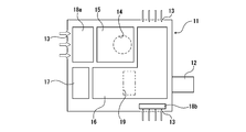
デジタルプロジェクタ11は、図5に示すように、外匣内に、例えば、キセノン放電ランプを備えた光源装置15と、いわゆる映像エンジン16と、電源装置17と、冷却機構とを備えている。12は投影レンズである。映像エンジン16は、例えばカラーフィルタ、画像素子および適宜の光学レンズなどを備えている。冷却機構は、図5において白抜きの矢印で示す冷却風によりキセノン放電ランプおよびその他の構成部材を冷却するものである。この冷却機構は、ランプ冷却用の給気用ファン18aおよびその他の構成部材の冷却用の給気用ファン18bと、排気用ファン19を備えている。図5において、13は、デジタルプロジェクタ11の外匣における背面および両側面の各々に形成された、例えばスリットなどの開口よりなる冷却風導入用開口部である。また、14は、デジタルプロジェクタ11の外匣における上面に形成された排気用開口部である。
キセノン放電ランプの具体的な構成例を示すと、例えば、定格消費電力が2~6kWであり、キセノンガスの封入圧力(常温換算)は1MPa以上、例えば1~2MPaであり、管壁負荷は30W/cm2 以上、例えば30~40W/cm2 である。
デジタルプロジェクタ11は、その内部の温度状態に合わせて冷却用の各ファン(18a、18b、19)の給気及び排気量が調節される。ここに、排気用ファン19は、排気量として18m3 /min以上の能力を有することが要求される。
デジタルプロジェクタ11は、その内部の温度状態に合わせて冷却用の各ファン(18a、18b、19)の給気及び排気量が調節される。ここに、排気用ファン19は、排気量として18m3 /min以上の能力を有することが要求される。
上記のプロジェクタ装置10においては、筐体20の内部に設けられた、デジタルプロジェクタ11を昇降可能に支持する昇降システムによって、当該デジタルプロジェクタ11を筐体本体21の内部から下方に降下可能に構成されている(図1および図2における斜線を付した矢印は、デジタルプロジェクタ11の昇降方向を示している。)。昇降システムとしては、従来のパンタグラフ方式の昇降システムによりデジタルプロジェクタ11を吊下支持するものや、以下において詳細に説明するようなワイヤにより吊下支持するものなどが挙げられる。
この例における昇降システム50は、巻き上げ装置により構成されている。具体的には、架台枠41の上面における4隅の位置に設けられた吊具51、および、固定部材43に設けられた、デジタルプロジェクタ11の略上面中央部に位置された吊具51の各々に、一端部が固定された複数本、この例では5本のワイヤ55によって、デジタルプロジェクタ11を吊下支持している。吊具51は、例えばねじ込み式であって、蓋体30が水平となる姿勢が維持された状態で昇降されるようワイヤ55の長さが調整可能に構成されている。
各ワイヤ55は、複数のガイドシーブ(みぞ車)54によって張架されて設けられており、他端部がそれぞれ共通のワイヤドラム52に固定されている。ワイヤドラム52は、回転軸が水平方向に延びる姿勢で配置されており、巻き取りモータ53によって回転駆動される。ワイヤドラム52および巻き取りモータ53が各ワイヤ55に共通のものであることにより、デジタルプロジェクタ11の昇降動作時において、デジタルプロジェクタ11を確実に適正な姿勢すなわち水平に維持することができる。
各ワイヤ55は、複数のガイドシーブ(みぞ車)54によって張架されて設けられており、他端部がそれぞれ共通のワイヤドラム52に固定されている。ワイヤドラム52は、回転軸が水平方向に延びる姿勢で配置されており、巻き取りモータ53によって回転駆動される。ワイヤドラム52および巻き取りモータ53が各ワイヤ55に共通のものであることにより、デジタルプロジェクタ11の昇降動作時において、デジタルプロジェクタ11を確実に適正な姿勢すなわち水平に維持することができる。
また、本発明のプロジェクタ装置においては、デジタルプロジェクタ11の昇降動作時において、デジタルプロジェクタ11の、筐体本体21に対する位置ないしは姿勢を規制する位置規制手段を備えた構成とされていることが好ましい。
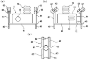
この例においては、図6に示すように、架台枠41に設けられた上下方向に延びる案内ロッド61と、案内ロッド61を案内する一対の案内ローラ62とにより構成された位置規制手段を備えた構成とされている。
案内ロッド61は、上端部が上方に向かうに従って小径となる尖頭状(円錐状)に形成されており、例えば、架台枠41の上面における対角の位置の2箇所に設けられている。
一対の案内ローラ62は、上下方向に延びる円柱状の案内ロッド移動路を挟んだ位置において、回転軸が水平方向に延びる姿勢で筐体本体21に対して固定されて設けられている。各々の案内ローラ62は、ローラ基体63の周面にガイド溝64が形成されてなるものであって、一対の案内ローラ62のガイド溝64によってロッド案内用空間Rが形成されている。そして、ロッド案内用空間Rが、平面視にて、案内ロッド61の外周輪郭形状と適合する形状となるよう各々の案内ローラ62の回転軸が互いに上下方向に変位した状態で位置されている。
この例においては、図6に示すように、架台枠41に設けられた上下方向に延びる案内ロッド61と、案内ロッド61を案内する一対の案内ローラ62とにより構成された位置規制手段を備えた構成とされている。
案内ロッド61は、上端部が上方に向かうに従って小径となる尖頭状(円錐状)に形成されており、例えば、架台枠41の上面における対角の位置の2箇所に設けられている。
一対の案内ローラ62は、上下方向に延びる円柱状の案内ロッド移動路を挟んだ位置において、回転軸が水平方向に延びる姿勢で筐体本体21に対して固定されて設けられている。各々の案内ローラ62は、ローラ基体63の周面にガイド溝64が形成されてなるものであって、一対の案内ローラ62のガイド溝64によってロッド案内用空間Rが形成されている。そして、ロッド案内用空間Rが、平面視にて、案内ロッド61の外周輪郭形状と適合する形状となるよう各々の案内ローラ62の回転軸が互いに上下方向に変位した状態で位置されている。
位置規制手段は、デジタルプロジェクタの昇降動作時に、蓋体の筐体に対する位置を規制することのできるものであれば、案内ロッドと案内ローラとによるものに限定されない。
而して、上記のプロジェクタ装置10においては、デジタルプロジェクタ11の外匣における上面に形成された排気用開口部14に、上下方向に延びる排気用ダクト70の一端部が接続され、図3に示すように、当該排気用ダクト70は、筐体本体21の上壁に形成された上方開口部28を介して筐体20外部に導出されている。そして、図1に示すように、排気用ダクト70の他端部は、天井裏に配設された排気用ファン71に接続されている。これにより、装置外部に延びる排気路Epが劇場区間Srと隔離された状態で形成されており、デジタルプロジェクタ11の排気に係る熱風ないしは温風(図1においては便宜上塗りつぶした矢印で示している。)が排気用ダクト70を介して装置外部に排出される。
そして、筐体本体21内部と天井裏空間とを連通させる開口が、筐体本体21の上壁および天井面に設けられて冷却風給気口29が形成され、これにより、天井裏に配設された冷却風供給用ファン75に接続された、装置外部に延びる給気路Spが、劇場空間Srと隔離された状態で形成されている。すなわち、図3(a),(b)を参照して説明すると、天井裏に配設された冷却風供給用ファン75からの冷却風(図3(a),(b)において白抜きの矢印で示す。)は、筐体本体21の上壁に形成された冷却風給気口29を介して、筐体20内部に供給され、デジタルプロジェクタ11の周囲に形成された冷却風流通路F(筐体20の内部空間)を流通する。その後、図5におけるデジタルプロジェクタ11に設けられた給気用ファン18a、18bによって、デジタルプロジェクタ11の外匣における背面および両側面の各々に形成された冷却風導入用開口部13から導入され、放電ランプおよびその他の構成部材が冷却される。
そして、筐体本体21内部と天井裏空間とを連通させる開口が、筐体本体21の上壁および天井面に設けられて冷却風給気口29が形成され、これにより、天井裏に配設された冷却風供給用ファン75に接続された、装置外部に延びる給気路Spが、劇場空間Srと隔離された状態で形成されている。すなわち、図3(a),(b)を参照して説明すると、天井裏に配設された冷却風供給用ファン75からの冷却風(図3(a),(b)において白抜きの矢印で示す。)は、筐体本体21の上壁に形成された冷却風給気口29を介して、筐体20内部に供給され、デジタルプロジェクタ11の周囲に形成された冷却風流通路F(筐体20の内部空間)を流通する。その後、図5におけるデジタルプロジェクタ11に設けられた給気用ファン18a、18bによって、デジタルプロジェクタ11の外匣における背面および両側面の各々に形成された冷却風導入用開口部13から導入され、放電ランプおよびその他の構成部材が冷却される。
天井裏に配設された冷却風供給用ファン75および排気用ファン71は、例えば18m3 /分以上の流量で、冷却風を供給する機能および排気に係る熱風を排出する機能を有するものである。
排気用ダクト70は、例えばデジタルプロジェクタ11の昇降方向に伸縮自在なベローズにより構成されており、デジタルプロジェクタ11の昇降動作に伴って伸縮される。
排気用ダクト70は、例えばデジタルプロジェクタ11の昇降方向に伸縮自在なベローズにより構成されており、デジタルプロジェクタ11の昇降動作に伴って伸縮される。
以下、上記のプロジェクタ装置10におけるデジタルプロジェクタ11の昇降動作について説明する。
このプロジェクタ装置10においては、図3(a),(b)にも示すように、デジタルプロジェクタ11は、通常、筐体20の内部に収容されて劇場空間Srと隔離されており、上述したように、動作時においては、放電ランプおよびその他の構成部材が冷却風によって冷却される。而して、ランプ交換などのメンテナンス作業を行う場合には、図4(a),(b)に示すように、デジタルプロジェクタ11が昇降システム50によって筐体20の内部から下方に降下される。すなわち、巻き取りモータ53が例えば逆転駆動されることによりワイヤドラム52が回転され、各ワイヤ55が同一の送り出し量で送り出されると共に排気用ダクト70が伸長されて蓋体30が水平となる姿勢が維持された状態で、デジタルプロジェクタ11が床面に対して所定の位置(例えば床面から80cm程度の位置)まで降下される。ここに、ワイヤ55の送り出し速度は、例えば7m/分以下の範囲内で適宜に設定することができ、一定であっても、変化させてもよい。例えば、デジタルプロジェクタ11が床面から所定の高さまで降下されたときに送り出し速度が床面に接近するに従って低下される(最終的には0m/分となる)よう巻き取りモータ53の動作を制御することができる。
なお、エアシリンダ45は、後述するように、デジタルプロジェクタ11が筐体20内部に収容された状態においては、圧縮空気が供給されて動作状態とされているが、デジタルプロジェクタ11を降下させる際には、圧縮空気の供給が停止されることにより、ピストンロッド46がシリンダチューブ47の下方位置に位置された状態とされる。
このプロジェクタ装置10においては、図3(a),(b)にも示すように、デジタルプロジェクタ11は、通常、筐体20の内部に収容されて劇場空間Srと隔離されており、上述したように、動作時においては、放電ランプおよびその他の構成部材が冷却風によって冷却される。而して、ランプ交換などのメンテナンス作業を行う場合には、図4(a),(b)に示すように、デジタルプロジェクタ11が昇降システム50によって筐体20の内部から下方に降下される。すなわち、巻き取りモータ53が例えば逆転駆動されることによりワイヤドラム52が回転され、各ワイヤ55が同一の送り出し量で送り出されると共に排気用ダクト70が伸長されて蓋体30が水平となる姿勢が維持された状態で、デジタルプロジェクタ11が床面に対して所定の位置(例えば床面から80cm程度の位置)まで降下される。ここに、ワイヤ55の送り出し速度は、例えば7m/分以下の範囲内で適宜に設定することができ、一定であっても、変化させてもよい。例えば、デジタルプロジェクタ11が床面から所定の高さまで降下されたときに送り出し速度が床面に接近するに従って低下される(最終的には0m/分となる)よう巻き取りモータ53の動作を制御することができる。
なお、エアシリンダ45は、後述するように、デジタルプロジェクタ11が筐体20内部に収容された状態においては、圧縮空気が供給されて動作状態とされているが、デジタルプロジェクタ11を降下させる際には、圧縮空気の供給が停止されることにより、ピストンロッド46がシリンダチューブ47の下方位置に位置された状態とされる。
一方、メンテナンス作業の終了後、デジタルプロジェクタ11を筐体本体21内に収容する場合には、巻き取りモータ53が例えば正転駆動されることによりワイヤドラム52が回転され、各ワイヤ55が同一の巻き上げ量で巻き取られると共に排気用ダクト70が短縮されて蓋体30が水平となる姿勢が維持された状態で、デジタルプロジェクタ11が上昇される。ここに、ワイヤ55の巻き取り速度は、例えば7m/分以下の範囲内で適宜に設定することができ、一定であっても、変化させてもよい。例えば、デジタルプロジェクタ11が床面から所定の高さまで上昇されたときに筐体本体21に接近するに従って巻き取り速度が低下される(最終的には0m/分となる)よう巻き取りモータ53の動作を制御することもできる。
デジタルプロジェクタ11が上昇される過程においては、図6(a)~(c)に示すように、各々の案内ロッド61が、対応する一対の案内ローラ62によって形成されるロッド案内用空間R内に挿入されて案内ロッド61が案内ローラ62によって案内される。これにより、デジタルプロジェクタ11の、筐体本体21に対する位置ないしは姿勢が規制される。
そして、図7(a)に示すように、各ワイヤ55が所定の巻き取り量で巻き取られて蓋体30が筐体本体21における蓋体受容装着部24に気密性緩衝部材35を介して当接されて筐体本体21の下方開口部23が蓋体30によって塞がれた状態とされると、巻き取りモータ53の駆動が停止される。このとき、蓋体30が筐体本体21の受容装着部24に収納される際の振動は気密性緩衝部材35によって低減される。巻き取りモータ53の駆動制御は、例えばリミットスイッチやセンサなどによる過巻き防止手段(図示せず)によって行うことができる。
この状態において、図7(b)に示すように、各エアシリンダ45に対して圧縮空気が供給されることにより、ピストンロッド46がシリンダチューブ47に対して上方向に作動され、気密性緩衝部材35を弾性的に圧潰しながら、蓋体30が上方に引き上げられる。これにより、蓋体30の筐体本体21に対する押圧状態が保持されて筐体20の内部が気密に密閉された空間とされると共に、デジタルプロジェクタ11の投影レンズ12が筐体20の映写窓25に対する適正な位置に配置された状態とされる(図1参照)。なお、図7(b)において、エアシリンダ45に供給される圧縮空気は、塗りつぶした矢印で示してあり、ピストンロッド46の移動方向を便宜上斜線を付した矢印で示している。また、蓋体30の移動方向を白抜きの矢印で示している。
而して、上記構成のプロジェクタ装置10によれば、基本的には、デジタルプロジェクタ11および昇降システム50などの全ての構成要素が筐体20内に収容されているので、劇場空間Srの美観を損なうことなく、劇場空間Sr内に設置することができて劇場空間Srを有効に利用することができる。しかも、デジタルシネマ用プロジェクタが密閉された筐体内に設置されているので、劇場空間内に発せられる冷却機構の動作音などの騒音を可及的に小さく低減することができると共に、冷却風および排気に係る熱風ないしは温風が劇場空間内に排出されることを回避することができ、より快適な劇場空間を提供することができる。
また、上記のプロジェクタ装置10によれば、次のような効果が得られる。
(1)メンテナンス作業を行うに際しては、デジタルプロジェクタ11をワイヤ55による昇降システム50によって降下させればよいので、劇場空間Srの天井付近の高所において作業を行う必要がなくなり、安全かつ確実に所期の作業を行うことができる。しかも、デジタルプロジェクタ11がワイヤ55によって吊下支持されていることにより、作業者は、デジタルプロジェクタ11の全周方向からアクセスすることができるので、メンテナンス作業を容易にかつ確実に行うことができて高い作業性を得ることができる。
(1)メンテナンス作業を行うに際しては、デジタルプロジェクタ11をワイヤ55による昇降システム50によって降下させればよいので、劇場空間Srの天井付近の高所において作業を行う必要がなくなり、安全かつ確実に所期の作業を行うことができる。しかも、デジタルプロジェクタ11がワイヤ55によって吊下支持されていることにより、作業者は、デジタルプロジェクタ11の全周方向からアクセスすることができるので、メンテナンス作業を容易にかつ確実に行うことができて高い作業性を得ることができる。
(2)筐体20を構成する筐体本体21における壁および蓋体30が遮音パネルによって形成されていることにより、筐体20自体を遮音性および吸音性が高いものとして構成することができる。さらに、エアシリンダ45の作動によって、蓋体30が気密性緩衝部材35を介して筐体本体21に対して押圧された状態が保持されて筐体20の気密構造が形成されることにより、筐体20は一層高い遮音性および吸音性を有するものとなる。すなわち、デジタルプロジェクタ11の冷却機構(ランプ冷却用の給気用ファン18aおよびその他の構成部材の冷却用の給気用ファン18b、並びに、排気用ファン19)の動作音などの騒音は、筐体20における壁を構成する遮音パネルによって遮蔽ないしは吸音されるので、筐体20がその下面が開閉可能に構成されたものでありながら、プロジェクタ装置10から劇場空間Sr内に発せられる騒音を可及的に小さく低減することができる。
具体的には例えば、デジタルプロジェクタ11自体から発せられる音の音圧(レベル)が約70dBA程度であるとき、上記構成のプロジェクタ装置10によれば、同様の方法により計測されるプロジェクタ装置10から発せられる音の音圧(レベル)を30dBA程度まで低減することができる。
また、例えばデジタルプロジェクタ11の自重の影響などによって、筐体20の気密性が低下することがなく、デジタルプロジェクタ11から発せられる例えば冷却機構の動作音などが劇場空間Srに漏れることを確実に防止することができる。
具体的には例えば、デジタルプロジェクタ11自体から発せられる音の音圧(レベル)が約70dBA程度であるとき、上記構成のプロジェクタ装置10によれば、同様の方法により計測されるプロジェクタ装置10から発せられる音の音圧(レベル)を30dBA程度まで低減することができる。
また、例えばデジタルプロジェクタ11の自重の影響などによって、筐体20の気密性が低下することがなく、デジタルプロジェクタ11から発せられる例えば冷却機構の動作音などが劇場空間Srに漏れることを確実に防止することができる。
(3)筐体20内におけるデジタルプロジェクタ11の上下方向の位置をエアシリンダ45を作動させることによって微調整することができる。このため、デジタルプロジェクタ11の昇降動作によって、あるいは、デジタルプロジェクタ11の自重によって、デジタルプロジェクタ11の投影レンズ12の位置の、筐体20における映写窓25の位置に対する位置ずれが生ずることを回避することができ、光学系を再調整するなどの作業が不要となる。
(4)デジタルプロジェクタ11の昇降動作時において、位置規制手段を構成する各々の案内ロッド61が、対応する一対の案内ローラ62によって形成されるロッド案内用空間R内に挿入されて案内ロッド61が案内ローラ62によって案内される。これにより、デジタルプロジェクタ11の、筐体本体21に対する位置ないしは姿勢が規制される。従って、デジタルプロジェクタ11の昇降動作時に多少の揺れが加わっても、ワイヤ55が撓んだり、蓋体30の水平性が著しく崩れたりすることがなく、デジタルプロジェクタ11の昇降動作を安全にかつ確実に行うことができる。
(5)筐体本体21と天井裏とが連通するよう形成された冷却風給気口29を介して装置外部に延びる給気路Sp、および、排気用ダクト70が筐体本体21の上方開口部28を介して装置外部に導出されることにより形成された排気路Epのいずれもが、劇場空間Srと隔離されているので、プロジェクタ装置10に供給される冷却風および排気に係る熱風ないしは温風(例えば40~50℃)が劇場空間Sr内に排出されることを回避することができる。
さらに、ベローズにより構成された排気用ダクト70によって、排気用ダクト70がデジタルプロジェクタ11に接続された状態を維持することができるので、デジタルプロジェクタ11が降下された状態にあっても、デジタルプロジェクタ11に対する冷却風の供給、排気を行うことができて、メンテンナンス作業後のデジタルプロジェクタ11の動作確認を筐体20内に収容することなく行うことができる。
さらに、ベローズにより構成された排気用ダクト70によって、排気用ダクト70がデジタルプロジェクタ11に接続された状態を維持することができるので、デジタルプロジェクタ11が降下された状態にあっても、デジタルプロジェクタ11に対する冷却風の供給、排気を行うことができて、メンテンナンス作業後のデジタルプロジェクタ11の動作確認を筐体20内に収容することなく行うことができる。
(6)装置外部から給気路を介して供給されるデジタルシネマ用プロジェクタを冷却する冷却風が、筐体内部において形成された冷却風流通路を流通されることによって、筐体の内部空間が冷却されると共にデジタルシネマ用プロジェクタがその外面側から冷却される。さらに、当該冷却風がデジタルシネマ用プロジェクタの内部に導入されることによって当該デジタルシネマ用プロジェクタが冷却されるので、デジタルプロジェクタの過度の温度上昇を確実に防止することができてデジタルシネマ用プロジェクタを正常に動作させることができる。
(7)排気路に設けられた排気用ファンおよび給気路に設けられた冷却風供給用ファンが劇場空間の天井裏に配設されていることにより、排気用ファンおよび冷却風供給用ファンの動作音などの騒音が劇場空間に漏れることを一層確実に防止することができる。
以上、本発明の実施形態について説明したが、本発明は上記の実施形態に限定されるものではなく、種々の変更を加えることができる。
例えば、筐体は下面が開閉可能に構成されていれば、筐体本体の開口部を蓋体により開閉する構成のものに限定されない。
また、デジタルプロジェクタを吊下支持するワイヤの本数、ワイヤの固定位置、エアシリンダの数およびその他の具体的な構成は、適宜変更することができる。
さらにまた、位置規制手段は、デジタルプロジェクタの昇降動作時に、蓋体の筐体に対する位置を規制することのできるものであれば、案内ロッドと案内ローラとによるものに限定されない。
さらにまた、蓋体の表面上に2つの気密性緩衝部材を所定の間隔をあけて互いに平行に延びるよう配設して、二重シール構造を形成するよう構成されていてもよい。また、気密性緩衝部材が筐体本体に設けられた構成とされていてもよい。
例えば、筐体は下面が開閉可能に構成されていれば、筐体本体の開口部を蓋体により開閉する構成のものに限定されない。
また、デジタルプロジェクタを吊下支持するワイヤの本数、ワイヤの固定位置、エアシリンダの数およびその他の具体的な構成は、適宜変更することができる。
さらにまた、位置規制手段は、デジタルプロジェクタの昇降動作時に、蓋体の筐体に対する位置を規制することのできるものであれば、案内ロッドと案内ローラとによるものに限定されない。
さらにまた、蓋体の表面上に2つの気密性緩衝部材を所定の間隔をあけて互いに平行に延びるよう配設して、二重シール構造を形成するよう構成されていてもよい。また、気密性緩衝部材が筐体本体に設けられた構成とされていてもよい。
10 プロジェクタ装置
11 デジタルシネマ用プロジェクタ(デジタルプロジェクタ)
12 投影レンズ
13 冷却風導入用開口部
14 排気用開口部
15 光源装置
16 映像エンジン
17 電源装置
18a ランプ冷却用の給気用ファン
18b 給気用ファン
19 排気用ファン
20 筐体
21 筐体本体
22 底壁
23 下方開口部
24 蓋体受容装着部
25 映写窓
26 映写用開口部
27 窓部材
28 上方開口部
29 冷却風給気口
30 蓋体
35 気密性緩衝部材
36 固定用金具
40 架台
41 架台枠
42 フレーム部分
43 固定部材
45 エアシリンダ
46 ピストンロッド
47 シリンダチューブ
50 昇降システム
51 吊具
52 ワイヤドラム
53 巻き取りモータ
54 ガイドシーブ(みぞ車)
55 ワイヤ
61 案内ロッド
62 一対の案内ローラ
63 ローラ基体
64 ガイド溝
70 排気用ダクト
71 排気用ファン
75 冷却風供給用ファン
80 映写機
C 天井面
Ep 排気路
F 冷却風流通路
Pr 映写室
R ロッド案内用空間
S スクリーン
Sp 給気路
Sr 劇場空間
11 デジタルシネマ用プロジェクタ(デジタルプロジェクタ)
12 投影レンズ
13 冷却風導入用開口部
14 排気用開口部
15 光源装置
16 映像エンジン
17 電源装置
18a ランプ冷却用の給気用ファン
18b 給気用ファン
19 排気用ファン
20 筐体
21 筐体本体
22 底壁
23 下方開口部
24 蓋体受容装着部
25 映写窓
26 映写用開口部
27 窓部材
28 上方開口部
29 冷却風給気口
30 蓋体
35 気密性緩衝部材
36 固定用金具
40 架台
41 架台枠
42 フレーム部分
43 固定部材
45 エアシリンダ
46 ピストンロッド
47 シリンダチューブ
50 昇降システム
51 吊具
52 ワイヤドラム
53 巻き取りモータ
54 ガイドシーブ(みぞ車)
55 ワイヤ
61 案内ロッド
62 一対の案内ローラ
63 ローラ基体
64 ガイド溝
70 排気用ダクト
71 排気用ファン
75 冷却風供給用ファン
80 映写機
C 天井面
Ep 排気路
F 冷却風流通路
Pr 映写室
R ロッド案内用空間
S スクリーン
Sp 給気路
Sr 劇場空間
Claims (10)
- 劇場空間の天井部に固定された筐体と、当該筐体の内部に設置されたデジタルシネマ用プロジェクタと、当該デジタルシネマ用プロジェクタをワイヤにより吊下支持する昇降システムとを備えてなり、
前記筐体は、スクリーンに対向する正面に映写窓が形成された、下方に開口する開口部を有する筐体本体と、当該筐体本体における開口部を開閉し、筐体本体と共に密閉空間を形成する蓋体とにより構成されており、
前記デジタルシネマ用プロジェクタが、前記昇降システムによって、前記筐体から下方に降下可能に構成されていることを特徴とするデジタルシネマ映画館用のプロジェクタ装置。 - 前記筐体の開口部を開閉する蓋体上には、前記デジタルシネマ用プロジェクタを支持する架台がエアシリンダを介して固定され、当該架台に前記ワイヤが固定されて当該デジタルシネマ用プロジェクタが吊下支持されており、
前記エアシリンダは、加圧空気が供給されることにより前記蓋体の前記筐体本体に対する押圧状態が保持されるよう作動するものであることを特徴とする請求項1に記載のデジタルシネマ映画館用のプロジェクタ装置。 - 前記デジタルシネマ用プロジェクタの昇降動作時において、当該デジタルシネマ用プロジェクタの、前記筐体本体に対する位置を規制する位置規制手段を備えており、
当該位置規制手段は、前記架台に設けられた上下方向に延びる案内ロッドと、前記筐体本体に対して回転軸が固定されて設けられた、当該案内ロッドを案内する一対の案内ローラとにより構成されていることを特徴とする請求項2に記載のデジタルシネマ映画館用のプロジェクタ装置。 - 劇場空間の天井部に固定された、内部に密閉空間を形成する筐体と、当該筐体の内部に設置された、冷却機構を備えたデジタルシネマ用プロジェクタと、当該デジタルシネマ用プロジェクタをワイヤにより吊下支持する昇降システムとを備えており、
前記筐体における壁が遮音パネルにより形成されており、
前記筐体は、下方に開口する開口部を有する筐体本体と、当該筐体本体における開口部を開閉する蓋体とにより構成されており、当該蓋体上には、前記デジタルシネマ用プロジェクタを支持する架台がエアシリンダを介して固定され、当該架台に前記ワイヤが固定されて当該デジタルシネマ用プロジェクタが吊下支持されており、
前記エアシリンダは、加圧空気が供給されることにより前記蓋体の前記筐体本体に対する押圧状態が保持されるよう作動するものであることを特徴とするデジタルシネマ映画館用のプロジェクタ装置。 - 前記蓋体および前記筐体本体のいずれか一方に、弾性体よりなる気密性緩衝部材が、当該蓋体および当該筐体本体との間に介在する状態で、設けられていることを特徴とする請求項4に記載のデジタルシネマ映画館用のプロジェクタ装置。
- 劇場空間の天井部に上壁部が固定された、内部に密閉空間を形成する筐体と、当該筐体の内部に設置された、冷却機構を備えたデジタルシネマ用プロジェクタとを備えてなり、
前記デジタルシネマ用プロジェクタを冷却する冷却風の給気路と排気路が、前記劇場空間と隔離された状態で、前記筐体の上壁を介して装置外部に延びるよう形成されており、
前記排気路は、前記デジタルシネマ用プロジェクタにおける排気用開口部に一端部が接続された排気用ダクトが、前記筐体の上壁に形成された上方開口部を介して、装置外部に導出されて形成されており、
前記筐体は、下面が開閉可能に構成され、内部に前記デジタルシネマ用プロジェクタを昇降可能に支持する昇降システムを備えており、
前記排気用ダクトが、前記デジタルシネマ用プロジェクタの昇降方向に伸縮自在なベローズにより構成されていることを特徴とするデジタルシネマ映画館用のプロジェクタ装置。 - 前記筐体は、前記上方開口部および下方に開口する下方開口部を有する筐体本体と、当該筐体本体における下方開口部を開閉する蓋体とにより構成されており、
当該蓋体および当該筐体本体のいずれか一方に、弾性体よりなる気密性緩衝部材が、当該蓋体および当該筐体本体との間に介在する状態で、設けられていることを特徴とする請求項6に記載のデジタルシネマ映画館用のプロジェクタ装置。 - 劇場空間の天井部に上壁部が固定された、内部に密閉空間を形成する筐体と、当該筐体の内部に設置された、冷却機構を備えたデジタルシネマ用プロジェクタとを備えてなり、
前記デジタルシネマ用プロジェクタを冷却する冷却風の給気路と排気路が、前記劇場空間と隔離された状態で、前記筐体の上壁を介して装置外部に延びるよう形成されており、
前記筐体の内部には、前記デジタルシネマ用プロジェクタを冷却する冷却風が流通される冷却風流通路が形成されていることを特徴とするデジタルシネマ映画館用のプロジェクタ装置。 - 前記排気路には排気用ファンが設けられており、当該排気用ファンは、前記劇場空間の天井裏に配設されていることを特徴とする請求項8に記載のデジタルシネマ映画館用のプロジェクタ装置。
- 前記給気路には冷却風供給用ファンが設けられており、当該冷却風供給用ファンは、前記劇場空間の天井裏に配設されていることを特徴とする請求項8または請求項9に記載のデジタルシネマ映画館用のプロジェクタ装置。
Applications Claiming Priority (6)
| Application Number | Priority Date | Filing Date | Title |
|---|---|---|---|
| JP2014-035349 | 2014-02-26 | ||
| JP2014035348A JP5708848B1 (ja) | 2014-02-26 | 2014-02-26 | デジタルシネマ映画館用のプロジェクタ装置 |
| JP2014035349A JP5720818B1 (ja) | 2014-02-26 | 2014-02-26 | デジタルシネマ映画館用のプロジェクタ装置 |
| JP2014-035348 | 2014-02-26 | ||
| JP2014-035347 | 2014-02-26 | ||
| JP2014035347A JP5708847B1 (ja) | 2014-02-26 | 2014-02-26 | デジタルシネマ映画館用のプロジェクタ装置 |
Publications (1)
| Publication Number | Publication Date |
|---|---|
| WO2015129565A1 true WO2015129565A1 (ja) | 2015-09-03 |
Family
ID=54008886
Family Applications (1)
| Application Number | Title | Priority Date | Filing Date |
|---|---|---|---|
| PCT/JP2015/054735 Ceased WO2015129565A1 (ja) | 2014-02-26 | 2015-02-20 | デジタルシネマ映画館用のプロジェクタ装置 |
Country Status (1)
| Country | Link |
|---|---|
| WO (1) | WO2015129565A1 (ja) |
Citations (13)
| Publication number | Priority date | Publication date | Assignee | Title |
|---|---|---|---|---|
| JPH0570078U (ja) * | 1992-02-26 | 1993-09-21 | 株式会社オーエス | 昇降装置を有するビデオプロジェクター |
| JPH08101458A (ja) * | 1994-10-03 | 1996-04-16 | Sony Corp | 電子機器用筐体 |
| JP2001343707A (ja) * | 2000-05-30 | 2001-12-14 | Hiroyuki Terasaki | 光学電子機器の防塵装置 |
| JP2002370896A (ja) * | 2001-04-10 | 2002-12-24 | Os:Kk | プロジェクター用昇降装置 |
| JP2003177465A (ja) * | 2001-08-17 | 2003-06-27 | Hae Yong Choi | 劇場の映像・音響システム構造 |
| JP2003233133A (ja) * | 2002-02-12 | 2003-08-22 | Canon Inc | 消音装置およびこれを備えた光学装置 |
| JP2004077639A (ja) * | 2002-08-13 | 2004-03-11 | Japan Servo Co Ltd | プロジェクタ保護装置構造体 |
| JP2008310134A (ja) * | 2007-06-15 | 2008-12-25 | Hitachi Ltd | プロジェクタ |
| JP2009042379A (ja) * | 2007-08-07 | 2009-02-26 | Sanyo Electric Co Ltd | プロジェクタの冷却装置 |
| JP2009048155A (ja) * | 2007-07-26 | 2009-03-05 | Sanyo Electric Co Ltd | 投写型映像表示装置 |
| JP2009145526A (ja) * | 2007-12-13 | 2009-07-02 | Seiko Epson Corp | プロジェクタ及び画像表示システム |
| JP2010282141A (ja) * | 2009-06-08 | 2010-12-16 | Sanyo Electric Co Ltd | 投写型映像表示装置 |
| WO2013145176A1 (ja) * | 2012-03-28 | 2013-10-03 | Necディスプレイソリューションズ株式会社 | プロジェクターの排気装置 |
-
2015
- 2015-02-20 WO PCT/JP2015/054735 patent/WO2015129565A1/ja not_active Ceased
Patent Citations (13)
| Publication number | Priority date | Publication date | Assignee | Title |
|---|---|---|---|---|
| JPH0570078U (ja) * | 1992-02-26 | 1993-09-21 | 株式会社オーエス | 昇降装置を有するビデオプロジェクター |
| JPH08101458A (ja) * | 1994-10-03 | 1996-04-16 | Sony Corp | 電子機器用筐体 |
| JP2001343707A (ja) * | 2000-05-30 | 2001-12-14 | Hiroyuki Terasaki | 光学電子機器の防塵装置 |
| JP2002370896A (ja) * | 2001-04-10 | 2002-12-24 | Os:Kk | プロジェクター用昇降装置 |
| JP2003177465A (ja) * | 2001-08-17 | 2003-06-27 | Hae Yong Choi | 劇場の映像・音響システム構造 |
| JP2003233133A (ja) * | 2002-02-12 | 2003-08-22 | Canon Inc | 消音装置およびこれを備えた光学装置 |
| JP2004077639A (ja) * | 2002-08-13 | 2004-03-11 | Japan Servo Co Ltd | プロジェクタ保護装置構造体 |
| JP2008310134A (ja) * | 2007-06-15 | 2008-12-25 | Hitachi Ltd | プロジェクタ |
| JP2009048155A (ja) * | 2007-07-26 | 2009-03-05 | Sanyo Electric Co Ltd | 投写型映像表示装置 |
| JP2009042379A (ja) * | 2007-08-07 | 2009-02-26 | Sanyo Electric Co Ltd | プロジェクタの冷却装置 |
| JP2009145526A (ja) * | 2007-12-13 | 2009-07-02 | Seiko Epson Corp | プロジェクタ及び画像表示システム |
| JP2010282141A (ja) * | 2009-06-08 | 2010-12-16 | Sanyo Electric Co Ltd | 投写型映像表示装置 |
| WO2013145176A1 (ja) * | 2012-03-28 | 2013-10-03 | Necディスプレイソリューションズ株式会社 | プロジェクターの排気装置 |
Similar Documents
| Publication | Publication Date | Title |
|---|---|---|
| CN109505430B (zh) | 剧场结构 | |
| CN103547751A (zh) | 可运输的沉浸式电影显示结构 | |
| CN103279080A (zh) | 影院环境智能调节装置 | |
| JP5928617B2 (ja) | デジタルシネマ映画館用のプロジェクタ装置 | |
| JP5708847B1 (ja) | デジタルシネマ映画館用のプロジェクタ装置 | |
| CN105247415B (zh) | 剧场结构及使用该剧场结构的多投影系统 | |
| JP5708848B1 (ja) | デジタルシネマ映画館用のプロジェクタ装置 | |
| CN103217965A (zh) | 影院环境智能调节方法 | |
| US9797150B1 (en) | Large format cinema screen and projection system | |
| KR200486362Y1 (ko) | 개폐형 공연 부스 장치 | |
| JP5720818B1 (ja) | デジタルシネマ映画館用のプロジェクタ装置 | |
| KR102216313B1 (ko) | 미세먼지 정화기능을 구비한 엣지커버형 led 조명등 | |
| WO2015129565A1 (ja) | デジタルシネマ映画館用のプロジェクタ装置 | |
| KR101675403B1 (ko) | 조명기구 | |
| KR20160104257A (ko) | 영사기 부스 시스템 | |
| CN203241795U (zh) | 影院环境智能调节装置 | |
| KR101272163B1 (ko) | 영상 시스템 및 그 제어방법 | |
| KR100941165B1 (ko) | 구형 스크린 영상표시시설 | |
| CN212394373U (zh) | 电影院景观座椅系统 | |
| KR20140119590A (ko) | 360도 영상 출력 시스템의 엘리베이션장치 | |
| CN208130520U (zh) | 一种飞行影院 | |
| CN211611595U (zh) | 一种吸顶式互动投影游戏装置 | |
| CN208188543U (zh) | 一种动画用演示装置 | |
| JP5262598B2 (ja) | 壁構造 | |
| KR200279696Y1 (ko) | 승강형 반사판을 갖는 프로젝터 시스템 |
Legal Events
| Date | Code | Title | Description |
|---|---|---|---|
| 121 | Ep: the epo has been informed by wipo that ep was designated in this application |
Ref document number: 15755476 Country of ref document: EP Kind code of ref document: A1 |
|
| NENP | Non-entry into the national phase |
Ref country code: DE |
|
| 122 | Ep: pct application non-entry in european phase |
Ref document number: 15755476 Country of ref document: EP Kind code of ref document: A1 |