WO2015129271A1 - モータ制御装置、これを使用した電動パワーステアリング装置および車両 - Google Patents
モータ制御装置、これを使用した電動パワーステアリング装置および車両 Download PDFInfo
- Publication number
- WO2015129271A1 WO2015129271A1 PCT/JP2015/000972 JP2015000972W WO2015129271A1 WO 2015129271 A1 WO2015129271 A1 WO 2015129271A1 JP 2015000972 W JP2015000972 W JP 2015000972W WO 2015129271 A1 WO2015129271 A1 WO 2015129271A1
- Authority
- WO
- WIPO (PCT)
- Prior art keywords
- motor
- drive circuit
- backup
- phase
- motor drive
- Prior art date
Links
Images


Classifications
-
- B—PERFORMING OPERATIONS; TRANSPORTING
- B62—LAND VEHICLES FOR TRAVELLING OTHERWISE THAN ON RAILS
- B62D—MOTOR VEHICLES; TRAILERS
- B62D5/00—Power-assisted or power-driven steering
- B62D5/04—Power-assisted or power-driven steering electrical, e.g. using an electric servo-motor connected to, or forming part of, the steering gear
- B62D5/0457—Power-assisted or power-driven steering electrical, e.g. using an electric servo-motor connected to, or forming part of, the steering gear characterised by control features of the drive means as such
- B62D5/0481—Power-assisted or power-driven steering electrical, e.g. using an electric servo-motor connected to, or forming part of, the steering gear characterised by control features of the drive means as such monitoring the steering system, e.g. failures
- B62D5/0484—Power-assisted or power-driven steering electrical, e.g. using an electric servo-motor connected to, or forming part of, the steering gear characterised by control features of the drive means as such monitoring the steering system, e.g. failures for reaction to failures, e.g. limp home
-
- B—PERFORMING OPERATIONS; TRANSPORTING
- B62—LAND VEHICLES FOR TRAVELLING OTHERWISE THAN ON RAILS
- B62D—MOTOR VEHICLES; TRAILERS
- B62D5/00—Power-assisted or power-driven steering
- B62D5/04—Power-assisted or power-driven steering electrical, e.g. using an electric servo-motor connected to, or forming part of, the steering gear
- B62D5/0457—Power-assisted or power-driven steering electrical, e.g. using an electric servo-motor connected to, or forming part of, the steering gear characterised by control features of the drive means as such
- B62D5/0481—Power-assisted or power-driven steering electrical, e.g. using an electric servo-motor connected to, or forming part of, the steering gear characterised by control features of the drive means as such monitoring the steering system, e.g. failures
- B62D5/0487—Power-assisted or power-driven steering electrical, e.g. using an electric servo-motor connected to, or forming part of, the steering gear characterised by control features of the drive means as such monitoring the steering system, e.g. failures detecting motor faults
-
- H—ELECTRICITY
- H02—GENERATION; CONVERSION OR DISTRIBUTION OF ELECTRIC POWER
- H02P—CONTROL OR REGULATION OF ELECTRIC MOTORS, ELECTRIC GENERATORS OR DYNAMO-ELECTRIC CONVERTERS; CONTROLLING TRANSFORMERS, REACTORS OR CHOKE COILS
- H02P29/00—Arrangements for regulating or controlling electric motors, appropriate for both AC and DC motors
- H02P29/02—Providing protection against overload without automatic interruption of supply
- H02P29/024—Detecting a fault condition, e.g. short circuit, locked rotor, open circuit or loss of load
- H02P29/028—Detecting a fault condition, e.g. short circuit, locked rotor, open circuit or loss of load the motor continuing operation despite the fault condition, e.g. eliminating, compensating for or remedying the fault
-
- H—ELECTRICITY
- H02—GENERATION; CONVERSION OR DISTRIBUTION OF ELECTRIC POWER
- H02P—CONTROL OR REGULATION OF ELECTRIC MOTORS, ELECTRIC GENERATORS OR DYNAMO-ELECTRIC CONVERTERS; CONTROLLING TRANSFORMERS, REACTORS OR CHOKE COILS
- H02P29/00—Arrangements for regulating or controlling electric motors, appropriate for both AC and DC motors
- H02P29/02—Providing protection against overload without automatic interruption of supply
- H02P29/032—Preventing damage to the motor, e.g. setting individual current limits for different drive conditions
Definitions
- the above-described conventional example requires a configuration for outputting two motor winding terminals from the motor, which complicates the internal connection of the motor, increases the number of components necessary for the connection processing, and increases the size of the motor.
- the ECU constituting the drive device has unsolved problems that the motor interface unit is complicated, the number of components is increased, and the size is increased. Therefore, the present invention has been made paying attention to the above-mentioned unsolved problems of the conventional example, and even when a short circuit failure occurs in the motor drive circuit using a normal motor with a simple configuration, the electromagnetic brake can be used. It is an object of the present invention to provide a motor control device capable of continuing drive control of an electric motor without occurrence, an electric power steering device using the same, and a vehicle.
- the motor control apparatus is applied to a motor control apparatus including an electric motor that generates a steering assist force in a steering mechanism.
- a motor control apparatus including an electric motor that generates a steering assist force in a steering mechanism.
- the vehicle according to the present invention includes the motor control device described above.
- the steering torque sensor 13 converts the steering torque into a torsion angle displacement of a torsion bar (not shown) interposed between the input shaft 12a and the output shaft 12b, and converts the torsion angle displacement into a resistance change or a magnetic change. It is configured to detect.
- the gate drive circuit 41A stops the supply of the gate signal to the field effect transistors Qk and Qk + 1 constituting the switching arm SWAj that has become abnormal. .
- a gate signal for turning off is supplied to the field effect transistor QAj of the main motor current cutoff unit 33A corresponding to the abnormal switching arm SWAj.
- the gate drive circuit 41B of the backup motor drive circuit 32B performs pulse width modulation based on the voltage command value V2 * and the triangular wave carrier signal Sc.
- Each of the main inverter circuit 42A and the backup inverter circuit 42B receives the battery current of the battery 27 via the noise filter 43, the power shut-off units 44A and 44B, and the current detection circuits 39A1 and 39B1, and smoothes the input side.
- the electrolytic capacitors CA and CB are connected.
- the main inverter circuit 42A and the backup inverter circuit 42B have field effect transistors (FETs) Q1 to Q6 as six switching elements, and three switching arms SWAa, SWAb in which two field effect transistors are connected in series. SWAc and SWBa, SWBb, and SWBc are connected in parallel.
- the gate signals output from the gate drive circuits 41A and 41B are input to the gates of the field effect transistors Q1 to Q6.
- the A-phase motor drive current Ia, the B-phase motor drive current Ib, and the C-phase motor drive current Ic are changed from the connection points between the field effect transistors of the switching arms SWAa, SWAb, SWAc and SWBa, SWBb, SWBc to the main motor.
- the three-phase motor windings La, Lb, and Lc of the three-phase electric motor 22 are energized via the current interrupters 33A and 33B.
- the switching arms SWAa, SWAb, SWAc and SWBa, SWBb, SWBc of the main inverter circuits 42A and 42B have one shunt resistor with the sources of the field effect transistors Q2, Q4, and Q6 serving as the lower arms connected to each other.
- the current detection circuits 39A2 and 39B2 are grounded. Thereby, motor currents I1a to I1c and I2a to I2c are detected by these current detection circuits 39A and 39B.
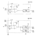
- Each of the current detection circuits 39A1, 39A2 and 39B1, 39B2 is configured as shown in FIGS. 7 (a) and (b). That is, current detection circuits 39A1 and 39B1 are inserted between the power supply sides of switching arms SWAa to SWAc and SWBa to SWBc and power supply cutoff units 44A and 44B, as shown in FIGS. 4 and 7A.
- Current detection shunt resistors 51A and 51B As shown in FIG. 7A, each of the current detection circuits 39A1 and 39B1 has an operational amplifier 39a to which the voltage across the shunt resistors 51A and 51B is input via the resistors R2 and R3, and an output signal of the operational amplifier 39a.
- the sample hold circuit 39s is mainly composed of a noise filter to be supplied.
- the current detection circuits 39A2 and 39B2 are for current detection inserted between the ground sides of the switching arms SWAa to SWAc and SWBa to SWBc. It has shunt resistors 52A and 52B.
- each of these current detection circuits 39A2 and 39B2 includes an operational amplifier 39a to which the voltage across the shunt resistors 52A and 52B is input via the resistors R2 and R3, and an output signal of the operational amplifier 39a.
- the lower current detection values IA2d and IB2d of each phase output from the sample hold circuit 39s and the peak values IA3d and IB3d output from the peak hold circuit 39p are supplied to the A / D converter 31c of the control arithmetic unit 31.
- the Control arithmetic unit 31 supplies lower voltage detection values IA2d and IB2d, peak values IA3d and IB3d, voltage command value V1 * for setting the duty ratio of the pulse width modulation signals of gate drive circuits 41A and 41B, and Based on V2 * , current detection values Iad, Ibd, and Icd of each phase are calculated.
- the main motor current cut-off section 33A has three current cut-off field effect transistors QAa, QAb, and QAc.
- the source of the field effect transistor QAa is connected to the connection point of the field effect transistors Q1 and Q2 of the switching arm SWAa of the main inverter circuit 42A via the motor voltage detection circuit 40A, and the drain is the A phase motor winding of the three phase motor winding L1. It is connected to the line La.
- the source of the field effect transistor QAb is connected to the connection point of the field effect transistors Q3 and Q4 of the switching arm SWAb of the main inverter circuit 42A via the motor voltage detection circuit 40A, and the drain is connected to the three-phase motor winding Lb. ing.
- the source of the field effect transistor QAc is connected to the connection point of the field effect transistors Q5 and Q6 of the switching arm SWAc of the main inverter circuit 42A via the motor voltage detection circuit 40A, and the drain is connected to the three-phase motor winding Lc. ing.
- the backup motor current cutoff unit 33B includes three current cutoff field effect transistors QBa, QBb, and QBc.
- the source of the field effect transistor QBa is connected to the connection point of the field effect transistors Q1 and Q2 of the switching arm SWBa of the backup inverter circuit 42B via the motor voltage detection circuit 40B, and the drain is connected to the three-phase motor winding La.
- the source of the field effect transistor QBb is connected to the connection point of the field effect transistors Q3 and Q4 of the switching arm SWBb of the backup inverter circuit 42B via the motor voltage detection circuit 40B, and the drain is connected to the three-phase motor winding Lb. ing.
- the source of the field effect transistor QBc is connected to the connection point of the field effect transistors Q5 and Q6 of the switching arm SWBc of the backup inverter circuit 42B via the motor voltage detection circuit 40B, and the drain is connected to the three-phase motor winding Lc. ing.
- the steering assist current command value calculator 34 calculates a steering assist current command value I * that is a current command value with reference to the steering assist current command value calculation map shown in FIG. 6 based on the steering torque Ts and the vehicle speed Vs. .
- This steering assist current command value calculation map is a characteristic diagram represented by a parabolic curve in which the horizontal axis represents the steering torque Ts and the vertical axis represents the steering assist current command value I *, as shown in FIG. It is configured.
- the main motor drive circuit 32A and the backup motor drive circuit 32B are normal, steering assist is made with reference to the normal current command value calculation curve Lno shown in FIG. 6 which is preset based on the steering torque Ts and the vehicle speed Vs.
- the current command value I * is calculated.
- the dq-axis current command value calculation unit 37 includes a d-axis target current calculation unit 37a, an induced voltage model calculation unit 37b, a q-axis target current calculation unit 37c, and a 2-phase / 3-phase conversion unit 37d.
- the d-axis target current calculation unit 37a calculates the d-axis target current Id * based on the post-compensation steering assist current command value I * ′ and the motor angular velocity ⁇ e.
- the q-axis target current Iq * is calculated based on the target current Id * , the post-compensation steering assist current command value I * ′, and the motor angular velocity ⁇ e.
- the two-phase / three-phase conversion unit 37d converts the d-axis target current Id * output from the d-axis target current calculation unit 37a and the q-axis target current Iq * output from the q-axis target current calculation unit 37c into a three-phase current.
- the command values are converted to Ia * , Ib * and Ic * .
- the control arithmetic unit 31 also determines the voltage command value V1 * for the main motor drive circuits 32A and 32B based on the calculated A-phase current command value Ia * , B-phase current command value Ib *, and C-phase current command value Ic *.
- a voltage command value calculation unit 38 for calculating V2 * is provided.
- the voltage command value calculation unit 38 detects the lower current detection value IA2d detected by the current detection circuits 39A2 and 39B2 from the A phase current command value Ia * , the B phase current command value Ib *, and the C phase current command value Ic *. Current detection values Iad, Ibd, and Icd calculated based on IB2d are subtracted.
- the voltage command value calculation unit 38 performs, for example, a PI control calculation or a PID control calculation on the calculated current deviations ⁇ Ia, ⁇ Ib, and ⁇ Ic. Thereby, three-phase voltage command values V1 * and V2 * for the main motor drive circuit 32A and the backup motor drive circuit 32B are calculated. Then, the calculated three-phase voltage command values V1 * and V2 * are output to the main motor drive circuit 32A and the backup motor drive circuit 32B. Here, the three-phase voltage command values V1 * and V2 * are output as the same value.
- control arithmetic unit 31 is provided between the main motor drive circuit 32A and the backup motor drive circuit 32B and the main motor current cutoff unit 33A and the backup motor current cutoff unit 33B.
- the motor phase voltages V1ma, V1mb, V1mc and V2ma, V2mb, V2mc detected by the motor voltage detection circuits 40A and 40B are input.
- the control arithmetic unit 31 includes an upper current detection value IA1d output from current detection circuits 39A1 and 39B1 for detecting a direct current supplied to the main inverter circuit 42A and the backup inverter circuit 42B, and IB1d is input.
- control arithmetic unit 31 has lower current detection values IA2d and IB2d output from current detection circuits 39A2 and 39B2 that detect a DC current flowing from the main inverter circuit 42A and the backup inverter circuit 42B to the ground as a motor current. Have been entered.
- the abnormality detection unit 31a outputs an abnormality detection signal SAb to the gate drive circuit 41B of the backup motor drive circuit 32B.
- the gate drive circuit 41B the field effect transistors Qk and Qk + 1 of the switching arm SWAj that becomes abnormal with respect to the switching arm SWBj in phase with the switching arm SWAj of the main motor drive circuit 32A that interrupts the current of the backup motor drive circuit 32B.
- the same gate signal as the gate signal supplied to the gates is supplied.
- a gate signal for turning on the field effect transistor QBj corresponding to the switching arm SWBj of the backup motor current cutoff unit 33B is supplied.
- the output of the operational amplifier 39a obtained by amplifying the voltage across the shunt resistors 51A and 51B, as shown in FIG.
- the pulse width modulation signal is supplied to a peak hold circuit 39p that holds the pulse width modulation signal for about one period or more.
- the peak (maximum) values IA3d and IB3d of the respective phases of the lower current detection values IA2d and IB2d can be detected quickly and accurately.
- gate signals for the field effect transistors Q1 to Q6 of the backup inverter circuit 42B are formed based on the voltage command value V2 * , and the formed gate signals are supplied to the gates of the field effect transistors Q1 to Q6.
- a gate signal that is turned on is supplied to the field effect transistor QD of the power cutoff unit 44B.
- the backup motor drive is performed at the same timing as the gate drive circuit 41A of the main motor drive circuit 32A supplies the gate signal for turning off the field effect transistors QAa to QAc of the main motor current cut-off section 33A.
- a gate signal for turning on the field effect transistors QBa to QBc of the backup motor current cutoff unit 33B is supplied from the gate drive circuit 41B of the circuit 32B.
- the drive of the three-phase electric motor 22 is instantaneously switched from the main motor drive circuit 32A to the backup motor drive circuit 32B, and in this state, the abnormality detection unit 31a causes a short circuit abnormality in each of the switching arms SWBa to SWBc of the backup inverter circuit 42B.
- the open abnormality is detected by the same method as the abnormality detection of the main inverter circuit 42A.
- the abnormality detection unit 31a detects a short-circuit failure or an open abnormality of the backup inverter circuit 42B, alarm information that prompts the alarm circuit 50 to repair the backup inverter circuit 42B is output.
- the abnormality detection unit 31a When the abnormality detection of the backup inverter circuit 42B is completed, the abnormality detection unit 31a outputs an abnormality detection end signal Sae to the main motor drive circuit 32A and the gate drive circuits 41A and 41B of the backup motor drive circuit 32B.
- the gate drive circuit 41B supplies the gate signal for turning off to the field effect transistors QBa to QBc of the backup motor current cutoff unit 33B, and at the same time, the gate drive circuit 41A supplies the main motor current.
- a gate signal for turning on is supplied to each of the field effect transistors QAa to QAc of the blocking unit 33A. Thereby, the drive of the three-phase electric motor 22 is returned from the backup motor drive circuit 32B to the main motor drive circuit 32A.
- the gate drive circuit 41B of the backup motor drive circuit 32B when the abnormality detection end signal Sae is input, the field effect transistors QBa to QBc of the backup motor current cutoff unit 33B are turned off and the backup inverter The gate signal supply to each of the field effect transistors Q1 to Q6 of the circuit 42B is stopped, and the gate signal for turning off the power supply cut-off unit 44B is supplied to stop the drive of the backup motor drive circuit 32B.
- Current deviations ⁇ Ia, ⁇ Ib and ⁇ Ic are calculated, and the calculated current deviations ⁇ Ia, ⁇ Ib and ⁇ Ic are subjected to PI control processing or PID control processing to calculate target voltage command values Va * , Vb * and Vc * .
- the calculated target voltage command values Va * , Vb *, and Vc * are output as voltage command values V1 * to the gate drive circuit 41A of the main motor drive circuit 32A.
- the control arithmetic unit 31 outputs the abnormality detection signals SAa and SAb having the logical value “0” to the gate drive circuits 41A and 41B.
- the gate drive circuit 41A outputs three high-level gate signals to the main motor current cutoff unit 33A. Therefore, the field effect transistors QAa to QAc of the main motor current cutoff unit 33A are turned on, and the main inverter circuit 42A and the three-phase motor windings L1 and L2 of the three-phase electric motor 22 are brought into conduction. The energization control for the three-phase electric motor 22 is possible.
- a high-level gate signal is output from the gate drive circuit 41A to the power cutoff unit 44A. Therefore, the field effect transistor QC of the power cutoff unit 44A is turned on, and the DC power from the battery 27 is supplied to the main inverter circuit 42A via the noise filter 43. Further, the gate drive circuit 41A forms a gate signal by performing a pulse width modulation process based on the voltage command value V1 * inputted from the control arithmetic unit 31, and the formed gate signal is used for each field effect of the main inverter circuit 42A. This is supplied to the gates of the transistors Q1 to Q6.
- the steering torque Ts is “0”, so the steering assist current command value I * is also “0” and is output from the main inverter circuit 42A.
- the A-phase to C-phase motor drive currents Ia to Ic are all “0”, and the three-phase electric motor 22 maintains the stopped state.
- the steering torque Ts increases, so that a large steering assist current command value I is obtained with reference to FIG. * Is calculated, and a large voltage command value V1 * corresponding to this is supplied to the gate drive circuit 41A of the main motor drive circuit 32A. Therefore, a gate signal having a duty ratio corresponding to the large voltage command value V1 * is output from the gate drive circuit 41A to the main inverter circuit 42A.
- IAb and C-phase motor drive current IAc are output. These are supplied to the three-phase motor windings La to Lc of the three-phase electric motor 22 through the field effect transistors QAa to QAc corresponding to the respective phases of the main motor current cutoff unit 33A.
- A is added to the sign of the current.
- B is added to the sign for the motor drive current output from the backup inverter circuit 42B.
- the three-phase electric motor 22 is rotationally driven to generate a large steering assist force corresponding to the target steering assist current command value I * corresponding to the steering torque Ts, and this steering assist force is transmitted via the reduction gear 21. Is transmitted to the output shaft 12b. For this reason, the steering wheel 11 can be steered with a light steering force. Thereafter, when the vehicle speed Vs increases, the steering assist current command value I * calculated accordingly decreases compared to when the vehicle is stationary, and the three-phase electric motor 22 moderately decreases according to the steering torque Ts and the vehicle speed Vs. Generated steering assist force.
- the abnormality detection process is always performed by the abnormality detection unit 31a for the main inverter circuit 42A.
- the gate signal is not supplied to the backup inverter circuit 42B, and the field effect transistors QBa to QBc of the backup motor current cut-off unit 33B and the field effect transistor QD of the power cut-off unit 44B are controlled to be turned off.
- An abnormality diagnosis cannot be performed because the drive is stopped. For this reason, there is no guarantee that the steering assist control can be continued when an abnormality occurs in the main inverter circuit 42A and the main inverter circuit 42A is switched to the backup inverter circuit 42B.
- a gate signal for turning on is supplied to each of the field effect transistors QBa to QBc of the backup motor current cutoff unit 33B, and a cutoff signal Sch is output to the gate drive circuit 41A of the main motor drive circuit 32A. For this reason, when the field effect transistors QBa to QBc of the backup motor current cutoff unit 33B are controlled to be turned on, the field effect transistors QAa to QAc of the main motor current cutoff unit 33A are controlled to be turned off almost simultaneously. .
- the field effect transistors Q1 to Q6 of the backup inverter circuit 42B of the backup motor drive circuit 32B are driven by the gate signal that is a pulse width modulation signal.
- an abnormality diagnosis state is reached in which the rotational drive of the three-phase electric motor 22 is continued by the respective phase motor drive currents IBa to IBc output from the backup inverter circuit 42B.
- the field effect transistors Q1 to Q6 of the backup inverter circuit 42B are turned on / off.
- the abnormality detection unit 31a can detect the short circuit abnormality and the open abnormality of each of the switching arms SWBa to SWBc.
- the abnormality detection end signal Sae is input to the gate drive circuits 41A and 41B.
- the field effect transistors QBa to QBc of the backup motor current cutoff unit 33B are controlled to be turned off, the field effect transistors QAa to QAc of the main motor current cutoff unit 33A are returned to the on state at substantially the same time. For this reason, the three-phase electric motor 22 returns from the drive state by the backup motor drive circuit 32B to the normal drive state by the main motor drive circuit 32A.
- abnormality information indicating that there is an abnormality in the backup system is output from the abnormality detection unit 31a to the alarm circuit 50, and the abnormality type and the location where the abnormality has occurred are stored in, for example, a nonvolatile memory connected to the control arithmetic unit 31.
- the abnormality type and the location where the abnormality has occurred can be immediately recognized from the abnormality information stored in the nonvolatile memory.
- the abnormality detection signal SAa indicating the switching arm SWAj in which an abnormality has occurred is supplied to the gate drive circuit 41A of the main motor drive circuit 32A.
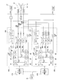
- this gate drive circuit 41A as shown in FIG. 10, for example, if an abnormality occurs in the switching arm SWAa, supply of the gate signal to the field effect transistors Q1, Q2 of the switching arm SWAa is stopped. At the same time, a gate signal for turning off the field effect transistor QAa is supplied to the corresponding field effect transistor QAa of the main motor current cutoff unit 33A.
- the A-phase drive signal is supplied to the three-phase electric motor 22 from the switching arm SWBa of the backup inverter circuit 42B of the backup motor drive circuit 32B.
- the B-phase drive signal and the C-phase drive signal are supplied from the switching arms SWAb and SWAc of the main inverter circuit 42A of the main motor drive circuit 32A as in the normal state. For this reason, it is possible to drive and control the three-phase electric motor 22 in exactly the same way as when the main inverter circuit 42A is normal. It is assumed that an abnormality has occurred in any one of the other switching arms SWAb and SWAc of the main inverter circuit 42A, or any two or three of the switching arms SWAa to SWAc. Also in this case, it is possible to drive the switching arm corresponding to the switching arm in which an abnormality has occurred by the backup motor drive circuit 32B to supply each phase drive signal to the three-phase electric motor 22.
- the main motor is between the switching arm SWAj where the abnormality has occurred and the J-phase coil of the three-phase electric motor 22. It is interrupted by the field effect transistor QAj of the current interrupting part 33A.
- the brake torque does not act, and the driving of the three-phase electric motor 22 can be continued satisfactorily.
- each phase drive signal of the three-phase electric motor 22 is switched from the main motor drive circuit 32A to the backup motor drive circuit 32B.
- the present invention is not limited to the above-described configuration, and when performing abnormality detection processing of the backup inverter circuit 42B of the backup motor drive circuit 32B, the above-described FIG.
- the in-phase components of the main inverter circuit 42A and the backup inverter circuit 42B may be switched one by one in order from the A-phase switching arms SWAa and SWBa, for example, and the abnormality detection processing of each switching arm SWBa to SWBc may be performed.
- the influence of delay and phase shift at the time of current switching may be reduced. it can.
- each phase switching arm SWAa to SWAc and SWBa to SWBc of the main motor driving circuits 32A and 32B is individually inserted with a shunt resistor to detect the motor current of each phase, One of the shunt resistors may be omitted and the motor current of the omitted phase may be calculated by calculation.
- control arithmetic unit 31 incorporated the A / D conversion part 31c was demonstrated, it is not limited to this, Current detection circuit 39A1, 39A2 and 39B1, 39B2 An A / D conversion unit may be provided on the output side.
- an electric motor was a three-phase electric motor was demonstrated, it is not limited to this, This invention is applicable also to a polyphase electric motor more than four phases.
- the motor control device according to the present invention is applied to the electric power steering device has been described.
- the present invention is not limited to this, and the electric brake device, the steer-by-wire system, and the motor for vehicle traveling are used.
- the present invention can be applied to any system that uses an electric motor such as a driving device.
- SYMBOLS 1 ... Vehicle, 3 ... Electric power steering apparatus, 11 ... Steering wheel, 12 ... Steering shaft, 13 ... Steering torque sensor, 13a ... Torsion bar, 13b ... Input side rotation angle sensor, 13c ... Output side rotation angle sensor, 18 ... Steering gear, 20 ... steering assist mechanism, 22 ... 3-phase electric motor, La ... A-phase motor winding, Lb ... B-phase motor winding, Lc ... C-phase motor winding, L1-L3 ... coil section, 25 ... motor Control device, 26 ... Vehicle speed sensor, 27 ... Battery, 31 ... Control operation device, 32A ... Main motor drive circuit, 32B ...
- Backup motor drive circuit 33A, 33B ... Motor current cut-off unit, 34 ... Steering auxiliary current command value calculation unit 35 ... compensation control calculation unit, 36 ... adder, 37 ... dq-axis current command value calculation unit, 38 ... voltage command value calculation unit, 39A , 39A2, 39B1, 39B2 ... current detection circuit, 40A, 40B ... voltage detection circuit, 41A, 41B ... gate drive circuit, 42A ... main inverter circuit, 42B ... backup inverter circuit, 44A, 44B ... power cut-off unit, 50 ... alarm circuit
Abstract
Description
上記要望に応えるために、多相電動モータの多相モータ巻線を例えば二重化し、二重化した多相モータ巻線に対して個別のインバータ部から電流を供給し、一方のインバータ部のスイッチング手段に導通不可となるオフ故障すなわちオープン故障が生じた場合に、故障が生じた故障スイッチング手段を特定し、故障スイッチング手段を除くスイッチング手段を制御するとともに、故障スイッチング手段を含む故障インバータ部以外の正常インバータ部を制御する故障時制御手段を有する多相回転機の制御装置およびこれを用いた電動パワーステアリング装置が提案されている(例えば、特許文献1参照)。
そこで、本発明は、上記従来例の未解決の課題に着目してなされたものであり、簡易な構成で、通常のモータを使用してモータ駆動回路にショート故障が生じた場合でも電磁ブレーキが発生することなく電動モータの駆動制御を継続することが可能なモータ制御装置、これを使用した電動パワーステアリング装置および車両を提供することを目的としている。
さらに、本発明に係る車両の一態様は、上述したモータ制御装置を備えている。
さらに、上記効果を有するモータ制御装置を含んで車両を構成するので、多相電動モータの少なくとも多重系統のモータ駆動回路の一つに異常が発生した場合でも多相モータ駆動電流を電動モータに供給して電動モータでのトルク発生を継続することができ、電動モータの信頼性を向上させる車両を提供することができる。
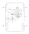
本発明に係る車両1は、図1に示すように、左右の転舵輪となる前輪2FR及び2FLと後輪2RR及び2RLを備えている。前輪2FR及び2FLは、電動パワーステアリング装置3によって転舵される。
電動パワーステアリング装置3は、ステアリングホイール11を有し、このステアリングホイール11に運転者から作用される操舵力がステアリングシャフト12に伝達される。このステアリングシャフト12は、入力軸12aと出力軸12bとを有する。入力軸12aの一端はステアリングホイール11に連結され、他端は操舵トルクセンサ13を介して出力軸12bの一端に連結されている。
操舵トルクセンサ13は、ステアリングホイール11に付与されて入力軸12aに伝達された操舵トルクを検出する。この操舵トルクセンサ13は、例えば、操舵トルクを入力軸12a及び出力軸12b間に介挿した図示しないトーションバーの捩れ角変位に変換し、この捩れ角変位を抵抗変化や磁気変化に変換して検出する構成とされている。
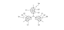
そして、ステータ22SのスロットSLに、3相を構成するA相、B相およびC相の多相モータ巻線La、LbおよびLcが巻装されている。これら多相モータ巻線La、LbおよびLcのそれぞれは、図3に示すように、例えば3つのコイル部L1、L2およびL3が並列に接続された構成を有し、これらコイル部L1~L3がスロットSLに3層に巻装されている。各相モータ巻線La、LbおよびLcは、一端が互いに接続されてスター結線とされ、他端がモータ制御装置25に接続されて個別にA相モータ駆動電流Ia、B相モータ駆動電流IbおよびC相モータ駆動電流Icが供給されている。
モータ制御装置25には、操舵トルクセンサ13で検出された操舵トルクTsおよび車速センサ26で検出された車速Vsが入力されるとともに、モータ回転角検出回路23から出力されるモータ回転角θmが入力される。
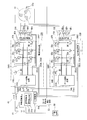
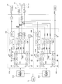
モータ制御装置25の具体的構成は、図4に示すように構成されている。すなわち、モータ制御装置25は、モータ電流指令値を演算する制御演算装置31と、この制御演算装置31から出力される3相の電圧指令値V1*およびV2*が個別に入力されるメインモータ駆動回路32Aおよびバックアップモータ駆動回路32Bとを備えている。加えて、これらメインモータ駆動回路32Aおよびバックアップモータ駆動回路32Bの出力側と3相電動モータ22の3相モータ巻線La~Lcとの間に介挿されたメイン用モータ電流遮断部33Aおよびバックアップ用モータ電流遮断部33Bを備えている。
一方、バックアップモータ駆動回路32Bのゲート駆動回路41Bは、制御演算装置31から電圧指令値V2*が入力されると、これら電圧指令値V2*と三角波のキャリア信号Scとをもとにパルス幅変調(PWM)した6つのゲート信号を形成し、これらゲート信号をバックアップインバータ回路42Bに出力する。また、ゲート駆動回路41Bは、電圧指令値V2*が入力されると電源遮断部44Bの電界効果トランジスタQDに対して該電界効果トランジスタQDをオン状態とするゲート信号を供給する。さらに、ゲート駆動回路41Bは、電圧指令値V2*が入力されると、バックアップ用モータ電流遮断部33Bの各電界効果トランジスタQBa~QBcに対して、各電解効果トランジスタQBa~QBcをオン状態とするゲート信号を供給する。
なお、6つのPWMゲート信号を制御演算装置31で共通生成してメインインバータ回路42Aおよびバックアップインバータ回路42Bに入力する構成としてもよい。
これらメインインバータ回路42Aおよびバックアップインバータ回路42Bは、6個のスイッチング素子としての電界効果トランジスタ(FET)Q1~Q6を有し、2つの電界効果トランジスタを直列に接続した3つのスイッチングアームSWAa、SWAb、SWAcおよびSWBa、SWBb、SWBcを並列に接続した構成を有する。
また、電流検出回路39A2および39B2は、図4および図7(b)に示すように、各スイッチングアームSWAa~SWAcおよびSWBa~SWBcの接地側と接地との間に介挿された電流検出用のシャント抵抗52Aおよび52Bを有する。これら電流検出回路39A2および39B2のそれぞれは、図7(b)に示すように、シャント抵抗52Aおよび52Bの両端電圧が抵抗R2およびR3を介して入力されるオペアンプ39aと、このオペアンプ39aの出力信号が供給されるノイズフィルタを含むピークホールド回路39pと、オペアンプ39aの出力信号が供給される主にノイズフィルタで構成されるサンプルホールド回路39sとで構成されている。
また、電界効果トランジスタQAbのソースがモータ電圧検出回路40Aを介してメインインバータ回路42AのスイッチングアームSWAbの電界効果トランジスタQ3およびQ4の接続点に接続され、ドレインが3相モータ巻線Lbに接続されている。
さらに、電界効果トランジスタQAcのソースがモータ電圧検出回路40Aを介してメインインバータ回路42AのスイッチングアームSWAcの電界効果トランジスタQ5およびQ6の接続点に接続され、ドレインが3相モータ巻線Lcに接続されている。
また、電界効果トランジスタQBbのソースがモータ電圧検出回路40Bを介してバックアップインバータ回路42BのスイッチングアームSWBbの電界効果トランジスタQ3およびQ4の接続点に接続され、ドレインが3相モータ巻線Lbに接続されている。
さらに、電界効果トランジスタQBcのソースがモータ電圧検出回路40Bを介してバックアップインバータ回路42BのスイッチングアームSWBcの電界効果トランジスタQ5およびQ6の接続点に接続され、ドレインが3相モータ巻線Lcに接続されている。
また、電源遮断部44Aおよび44Bのそれぞれは、1つの電界効果トランジスタ(FET)QCおよびQDと寄生ダイオードとの並列回路で構成されている。加えて、電界効果トランジスタQCおよびQDのドレインがノイズフィルタ43を介してバッテリー27に接続され、ソースがメインインバータ回路42Aおよびバックアップインバータ回路42Bに接続されている。
そして、メインモータ駆動回路32Aおよびバックアップモータ駆動回路32Bの正常時には操舵トルクTsおよび車速Vsをもとに予め設定された図6で実線図示の正常時電流指令値算出曲線Lnoを参照して操舵補助電流指令値I*を算出する。
そして、補償制御演算部35は、算出した指令値補償値Icomを操舵補助電流指令値演算部34から出力される操舵補助電流指令値I*に加算器36で加算することにより、補償後操舵補助電流指令値I*′を算出し、この補償後操舵補助電流指令値I*′をd-q軸電流指令値演算部37に出力する。
d軸目標電流算出部37aは、補償後操舵補助電流指令値I*′とモータ角速度ωeとに基づいてd軸目標電流Id*を算出する。
誘起電圧モデル算出部37bは、モータ回転角θおよびモータ角速度ωeに基づいてd-q軸誘起電圧モデルEMF(Electro Magnetic Force)のd軸EMF成分ed(θ)およびq軸EMF成分eq(θ)を算出する。
q軸目標電流算出部37cは、誘起電圧モデル算出部37bから出力されるd軸EMF成分ed(θ)およびq軸EMF成分eq(θ)とd軸目標電流算出部37aから出力されるd軸目標電流Id*と補償後操舵補助電流指令値I*′とモータ角速度ωeとに基づいてq軸目標電流Iq*を算出する。
2相/3相変換部37dは、d軸目標電流算出部37aから出力されるd軸目標電流Id*とq軸目標電流算出部37cから出力されるq軸目標電流Iq*とを3相電流指令値Ia*、Ib*およびIc*に変換する。
さらに、制御演算装置31には、図4に示すように、メインインバータ回路42Aおよびバックアップインバータ回路42Bに供給される直流電流を検出する電流検出回路39A1および39B1から出力される上側電流検出値IA1dおよびIB1dが入力されている。なおさらに、制御演算装置31には、メインインバータ回路42Aおよびバックアップインバータ回路42Bから接地に流れる直流電流をモータ電流として検出する電流検出回路39A2および39B2から出力される下側電流検出値IA2dおよびIB2dが入力されている。
メインインバータ回路42Aにおける例えば下アーム側の電界効果トランジスタQ2、Q4及びQ6の何れか1つにショート故障が発生すると、ショート故障を生じたスイッチングアームSWAi(i=a,b,c)からメイン用モータ電流遮断部33Aに出力されるモータ駆動電流Iiが流れなくなる。このことから、モータ電圧検出回路40Aで検出される相検出電圧Viが接地電位近くまで低下し、ショート故障の発生による異常と判断することができる。
さらには、メインインバータ回路42Aの上アームを構成する電界効果トランジスタQ1、Q3及びQ5の何れか1つにショート故障が発生した場合には、該当する電圧検出回路V1miの電圧が高い状態を維持する。このことからこの検出電圧から上アームのショート故障を判別することができる。
メインインバータ回路42Aを構成する電界効果トランジスタ(FET)のオープン故障又はショート故障を検出したときに、異常が発生した相のスイッチングアームSWAj(j=a、b及びc)の電界効果トランジスタQk(k=1、3、5)及びQk+1のゲートへのゲート信号の供給を停止させる異常検出信号SAaをゲート駆動回路41Aに出力する。これとともに、該当するメイン用モータ電流遮断部33Aの電流遮断用の電界効果トランジスタQAkに対してオフ信号を出力する。
この場合には、制御演算装置31は、メインモータ駆動回路32Aに電圧指令値V1*を出力している状態で、バックアップモータ駆動回路32Bに対して電圧指令値V1*と同じ値の電圧指令値V2*をバックアップモータ駆動回路32Bのゲート駆動回路41Bに出力する。このゲート駆動回路41Bでは、電圧指令値V2*に基づいてバックアップインバータ回路42Bの各電界効果トランジスタQ1~Q6に対するゲート信号を形成し、形成したゲート信号を各電界効果トランジスタQ1~Q6のゲートに供給するととともに、電源遮断部44Bの電界効果トランジスタQDに対してオン状態となるゲート信号を供給する。この状態で、メインモータ駆動回路32Aのゲート駆動回路41Aでメイン用モータ電流遮断部33Aの各電界効果トランジスタQAa~QAcに対してオフ状態とするゲート信号を供給するタイミングと同一タイミングでバックアップモータ駆動回路32Bのゲート駆動回路41Bからバックアップ用モータ電流遮断部33Bの各電界効果トランジスタQBa~QBcに対してオン状態とするゲート信号を供給する。
図示しないイグニッションスイッチがオフ状態であって車両が停止していると共に、操舵補助制御処理も停止している作動停止状態であるときには、モータ制御装置25の制御演算装置31が非作動状態となっている。このため、制御演算装置31で実行される操舵補助制御処理および異常監視処理は停止されている。したがって、3相電動モータ22は作動を停止しており、操舵補助機構10への操舵補助力の出力を停止している。
そして、算出した目標電圧指令値Va*、Vb*およびVc*を電圧指令値V1*としてメインモータ駆動回路32Aのゲート駆動回路41Aに出力する。また、制御演算装置31は、メインインバータ回路42Aが正常であるので、論理値“0”の異常検出信号SAaおよびSAbをゲート駆動回路41Aおよび41Bに出力する。
さらに、ゲート駆動回路41Aでは、制御演算装置31から入力される電圧指令値V1*に基づいてパルス幅変調処理を行ってゲート信号を形成し、形成したゲート信号をメインインバータ回路42Aの各電界効果トランジスタQ1~Q6のゲートに供給する。
しかしながら、車両の停止状態または車両の走行開始状態でステアリングホイール11を操舵して所謂据え切りを行うと、操舵トルクTsが大きくなることにより、図6を参照して、大きな操舵補助電流指令値I*が算出され、これに応じた大きな電圧指令値V1*がメインモータ駆動回路32Aのゲート駆動回路41Aに供給される。このため、ゲート駆動回路41Aから大きな電圧指令値V1*に応じたデューティ比のゲート信号がメインインバータ回路42Aに出力される。
その後、車速Vsが増加すると、これに応じて算出される操舵補助電流指令値I*が据え切り時に比較して低下して3相電動モータ22で操舵トルクTsおよび車速Vsに応じて適度に減少させた操舵補助力を発生する。
この異常検出処理では、メインモータ駆動回路32Aのゲート駆動回路41Aに出力されている電圧指令値V1*と同一値の電圧指令値V2*をバックアップモータ駆動回路32Bのゲート駆動回路41Bに出力することにより開始する。
バックアップモータ駆動回路32Bのゲート駆動回路41Bでは電圧指令値V2*が入力されることにより、前述したメインモータ駆動回路32Aのゲート駆動回路41Aと同様に、電圧指令値V2*に基づいてバックアップインバータ回路42Bの各電界効果トランジスタQ1~Q6に対するゲート信号を形成する。そして、形成したゲート信号を各電界効果トランジスタQ1~Q6に出力するとともに、電源遮断部44Bの電界効果トランジスタQDに対してオン状態とするゲート信号を供給する。
このため、バックアップ用モータ電流遮断部33Bの各電界効果トランジスタQBa~QBcがオン状態に制御されると略同時にメイン用モータ電流遮断部33Aの各電界効果トランジスタQAa~QAcがオフ状態に制御される。
この異常診断状態となると、バックアップインバータ回路42Bの各電界効果トランジスタQ1~Q6がオン・オフ駆動される。これにより、前述したメインモータ駆動回路32Aのメインインバータ回路42Aと同様に、異常検出部31aで各スイッチングアームSWBa~SWBcのショート異常及びオープン異常を検出することができる。
このため、3相電動モータ22がバックアップモータ駆動回路32Bによる駆動状態からメインモータ駆動回路32Aによる正常駆動状態に復帰する。
このため、車両をサービスステーション等に持って行くことにより、不揮発性メモリに記憶された異常情報から異常種別と異常発生個所とを直ちに認識することができる。
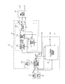
このゲート駆動回路41Aでは、図10に示すように、例えばスイッチングアームSWAaに異常が発生したものとすると、スイッチングアームSWAaの各電界効果トランジスタQ1,Q2に対するゲート信号の供給を停止する。これとともに、メイン用モータ電流遮断部33Aの該当する電界効果トランジスタQAaに対して該電界効果トランジスタQAaをオフするゲート信号を供給する。
これによって、図10に示すように、バックアップインバータ回路42BのA相に対応するスイッチングアームSWBaの電界効果トランジスタQ1及びQ2に今までメインモータ駆動回路32Aのメインインバータ回路42AのスイッチングアームSWAaの電界効果トランジスタQ1及びQ2と同じゲート信号が供給される。これと同時に、電源遮断部44Bの電界効果トランジスタQDがオン状態に制御され、さらにバックアップ用モータ電流遮断部33Bの電界効果トランジスタQBaがオン状態に制御される。これによって、スイッチングアームSWBaによって形成されるA相モータ駆動電流IBaが3相電動モータ22のA相モータ巻線Laに供給される。
このため、3相電動モータ22をメインインバータ回路42Aが正常である場合と全く同様に駆動制御することができる。
なお、メインインバータ回路42Aの他のスイッチングアームSWAb及びSWAcの何れか一方、又はスイッチングアームSWAa~SWAcの何れか2つ又は3つに異常が発生したとする。この場合にも、バックアップモータ駆動回路32Bによって異常を生じたスイッチングアームに相当するスイッチングアームを駆動して各相駆動信号を3相電動モータ22に供給することができる。
なお、メインインバータ回路42Aに異常が発生した場合も、警報回路50で警報を発してサービスステーションへの立ち寄りを促すとともに、その異常種別と異常発生個所とを制御演算装置31に接続した不揮発性メモリに記憶しておく。これにより、サービスステーションでの修理作業を容易に行うことができる。
しかも、正常なメインモータ駆動回路32Aと同様のモータ駆動信号をバックアップモータ駆動回路32Bから供給することができ、正常時と遜色ない操舵補助制御を継続することができる。このとき、運転者には警報を発して修理点検ステーションへの立ち寄りを促すことができる。
しかしながら、本発明は、上記構成に限定されるものではなく、バックアップモータ駆動回路32Bのバックアップインバータ回路42Bの異常検出処理を行う場合に、3相分同時に切り換える場合に代えて、前述した図10に示すように、メインインバータ回路42A及びバックアップインバータ回路42Bの同相分を、例えばA相スイッチングアームSWAa及びSWBaから順に一相ずつ切り換えて各スイッチングアームSWBa~SWBcの異常検出処理を行うようにしてもよい。
この場合には、3相電動モータ22に対するメインインバータ回路42Aのスイッチングアーム及びバックアップインバータ回路42Bのスイッチングアームが1つずつであるので、電流切り換え時の遅れや位相ずれの生じる影響を少なくすることができる。
また、上記実施形態においては、電動モータが3相電動モータである場合について説明したが、これに限定されるものではなく、4相以上の多相電動モータにも本発明を適用することができる。
また、上記実施形態においては、本発明によるモータ制御装置を電動パワーステアリング装置に適用した場合について説明したが、これに限定されるものではなく、電動ブレーキ装置、ステアバイワイヤシステム、車両走行用のモータ駆動装置等の電動モータを使用する任意のシステムに本発明を適用することができる。
ここでは、限られた数の実施形態を参照しながら説明したが、権利範囲はそれらに限定されるものではなく、上記の開示に基づく各実施形態の改変は当業者にとって自明のことである。
Claims (7)
- 多相電動モータを駆動制御するメインモータ駆動回路と、
該メインモータ駆動回路に異常が発生したときに前記多相電動モータを駆動制御する前記多相電動モータに前記メインモータ駆動回路と並列に接続されたバックアップモータ駆動回路と、
前記メインモータ駆動回路及び前記バックアップモータ駆動回路の異常診断を行う異常診断部とを備え、
前記メインモータ駆動回路のみで前記多相電動モータを駆動する正常駆動状態と、該正常駆動状態で前記メインモータ駆動回路の前記異常診断部による診断結果が異常であるときに、異常となった相出力部のモータ電流を遮断するとともに、遮断した相出力部を同相の前記バックアップモータ駆動回路の相出力部に切り換えて前記多相電動モータを駆動するバックアップ駆動状態とを備えているモータ制御装置。 - 前記メインモータ駆動回路の多相出力側と前記多相電動モータとの間にメイン用モータ電流遮断部が設けられ、前記バックアップモータ駆動回路の多相出力側と前記多相電動モータとの間にバックアップ用電流遮断部が設けられている請求項1に記載のモータ制御装置。
- 前記異常診断部は、前記メインモータ駆動回路の異常診断を、当該メインモータ駆動回路で前記多相電動モータを駆動している正常駆動状態であるときに行い、前記バックアップモータ駆動回路の異常診断を、前記メインモータ駆動回路で前記多相電動モータを駆動しているときに、当該メインモータ駆動回路及び前記バックアップモータ駆動回路の互いに同相の出力部の少なくとも一部を切り換えることにより行う請求項1又は2に記載のモータ制御装置。
- 前記異常診断部は、前記バックアップモータ駆動回路の異常診断を、前記メインモータ駆動回路で前記多相電動モータを駆動しているときに、当該メインモータ駆動回路及び前記バックアップモータ駆動回路の互いの同相出力を全て切り換えることにより行う請求項3に記載のモータ制御装置。
- 前記異常診断部は、前記バックアップモータ駆動回路の異常診断を、前記メインモータ駆動回路で前記多相電動モータを駆動しているときに、当該メインモータ駆動回路及び前記バックアップモータ駆動回路の互いの同相出力を1相ずつ切り換えながら行う請求項3に記載のモータ制御装置。
- ステアリング機構に操舵補助力を発生させる電動モータを含むモータ制御装置を前記請求項1から5の何れか1項に記載のモータ制御装置で構成した電動パワーステアリング装置。
- 前記請求項1から5の何れか1項に記載のモータ制御装置を備えた車両。
Priority Applications (4)
| Application Number | Priority Date | Filing Date | Title |
|---|---|---|---|
| EP15754550.0A EP3113355B1 (en) | 2014-02-28 | 2015-02-26 | Motor control device and electric power-steering device and vehicle using said motor control device |
| CN201580006188.3A CN105981291B (zh) | 2014-02-28 | 2015-02-26 | 马达控制装置、使用该马达控制装置的电动助力转向装置及车辆 |
| US15/115,001 US9771099B2 (en) | 2014-02-28 | 2015-02-26 | Motor control device and electric power-steering device and vehicle using said motor control device |
| JP2015539992A JP5907314B2 (ja) | 2014-02-28 | 2015-02-26 | モータ制御装置、これを使用した電動パワーステアリング装置および車両 |
Applications Claiming Priority (2)
| Application Number | Priority Date | Filing Date | Title |
|---|---|---|---|
| JP2014038424 | 2014-02-28 | ||
| JP2014-038424 | 2014-02-28 |
Publications (1)
| Publication Number | Publication Date |
|---|---|
| WO2015129271A1 true WO2015129271A1 (ja) | 2015-09-03 |
Family
ID=54008604
Family Applications (1)
| Application Number | Title | Priority Date | Filing Date |
|---|---|---|---|
| PCT/JP2015/000972 WO2015129271A1 (ja) | 2014-02-28 | 2015-02-26 | モータ制御装置、これを使用した電動パワーステアリング装置および車両 |
Country Status (5)
| Country | Link |
|---|---|
| US (1) | US9771099B2 (ja) |
| EP (1) | EP3113355B1 (ja) |
| JP (1) | JP5907314B2 (ja) |
| CN (1) | CN105981291B (ja) |
| WO (1) | WO2015129271A1 (ja) |
Cited By (3)
| Publication number | Priority date | Publication date | Assignee | Title |
|---|---|---|---|---|
| CN105429561A (zh) * | 2015-12-28 | 2016-03-23 | 珠海格力电器股份有限公司 | 一种电机控制电路 |
| JP2018064432A (ja) * | 2016-10-14 | 2018-04-19 | トヨタ自動車株式会社 | 故障判断装置 |
| KR20180083930A (ko) * | 2016-01-05 | 2018-07-23 | 히다치 오토모티브 시스템즈 가부시키가이샤 | 인버터 제어 장치, 모터 구동 장치 및 전동 파워 스티어링 장치 |
Families Citing this family (14)
| Publication number | Priority date | Publication date | Assignee | Title |
|---|---|---|---|---|
| JP6083428B2 (ja) * | 2014-12-16 | 2017-02-22 | トヨタ自動車株式会社 | 車両の電動パワーステアリング装置 |
| JP2017184530A (ja) * | 2016-03-31 | 2017-10-05 | ファナック株式会社 | 複数の巻線を有するモータ制御装置 |
| CN109952702A (zh) * | 2016-11-18 | 2019-06-28 | 三菱电机株式会社 | 异常检测装置 |
| WO2018163363A1 (ja) * | 2017-03-09 | 2018-09-13 | 三菱電機株式会社 | 電動機の駆動装置および冷凍サイクル適用機器 |
| KR102442208B1 (ko) * | 2017-08-08 | 2022-09-13 | 주식회사 만도 | 모터 구동 제어 장치 및 조향 시스템 |
| US20190184832A1 (en) * | 2017-12-19 | 2019-06-20 | Ford Global Technologies, Llc | Vehicle power system with back electromagnetic field blocking |
| US11498611B2 (en) * | 2018-05-11 | 2022-11-15 | Nidec Corporation | Motor control device, driving device, and power steering device |
| DE102018207542B4 (de) * | 2018-05-15 | 2021-01-14 | Volkswagen Aktiengesellschaft | Verfahren und Vorrichtung für eine Steuerung eines sicherheitsrelevanten Vorganges, sowie Fahrzeug |
| DE102018114828B3 (de) * | 2018-06-20 | 2019-07-25 | Thyssenkrupp Ag | Kraftfahrzeuglenkung mit einem redundant ausgelegten Steuergerät |
| JP7120075B2 (ja) * | 2019-02-26 | 2022-08-17 | トヨタ自動車株式会社 | 車両の制御装置 |
| DE102019105761A1 (de) * | 2019-03-07 | 2020-09-10 | Avl Software And Functions Gmbh | Fahrzeug mit einem Inverter und Verfahren zur Erhöhung der Lebensdauer eines Inverters |
| JP7243519B2 (ja) * | 2019-08-15 | 2023-03-22 | 株式会社デンソー | 回転電機制御装置 |
| DE102020207122A1 (de) | 2020-06-08 | 2021-12-09 | Zf Friedrichshafen Ag | Anordnung und Verfahren zur Ansteuerung eines Elektromotors für eine Fahrzeuglenkung |
| EP4273025A1 (de) * | 2022-05-06 | 2023-11-08 | thyssenkrupp Presta Aktiengesellschaft | Steer-by-wire-lenksystem und verfahren zum betreiben eines steer-by-wire-lenksystems in einem normalbetriebsmodus und in einem sonderbetriebsmodus |
Citations (3)
| Publication number | Priority date | Publication date | Assignee | Title |
|---|---|---|---|---|
| JP2008132919A (ja) * | 2006-11-29 | 2008-06-12 | Nsk Ltd | 電動パワーステアリング制御装置 |
| JP2009067174A (ja) * | 2007-09-12 | 2009-04-02 | Nsk Ltd | 電動パワーステアリング装置の制御装置 |
| WO2009119462A1 (ja) * | 2008-03-25 | 2009-10-01 | 株式会社サンメディカル技術研究所 | 補助人工心臓ポンプ駆動装置及び補助人工心臓システム |
Family Cites Families (4)
| Publication number | Priority date | Publication date | Assignee | Title |
|---|---|---|---|---|
| JP2884942B2 (ja) * | 1992-09-17 | 1999-04-19 | 株式会社日立製作所 | 電気車制御装置 |
| CN102549905B (zh) * | 2009-09-17 | 2014-11-05 | 东芝三菱电机产业系统株式会社 | 功率转换装置 |
| JP4998836B2 (ja) * | 2009-09-30 | 2012-08-15 | 株式会社デンソー | 多相回転機の制御装置、および、これを用いた電動パワーステアリング装置 |
| US20130285584A1 (en) * | 2012-04-27 | 2013-10-31 | Samsung Electro-Mechanics Co., Ltd. | Motor driving apparatus and method |
-
2015
- 2015-02-26 EP EP15754550.0A patent/EP3113355B1/en active Active
- 2015-02-26 CN CN201580006188.3A patent/CN105981291B/zh active Active
- 2015-02-26 WO PCT/JP2015/000972 patent/WO2015129271A1/ja active Application Filing
- 2015-02-26 US US15/115,001 patent/US9771099B2/en active Active
- 2015-02-26 JP JP2015539992A patent/JP5907314B2/ja active Active
Patent Citations (3)
| Publication number | Priority date | Publication date | Assignee | Title |
|---|---|---|---|---|
| JP2008132919A (ja) * | 2006-11-29 | 2008-06-12 | Nsk Ltd | 電動パワーステアリング制御装置 |
| JP2009067174A (ja) * | 2007-09-12 | 2009-04-02 | Nsk Ltd | 電動パワーステアリング装置の制御装置 |
| WO2009119462A1 (ja) * | 2008-03-25 | 2009-10-01 | 株式会社サンメディカル技術研究所 | 補助人工心臓ポンプ駆動装置及び補助人工心臓システム |
Cited By (5)
| Publication number | Priority date | Publication date | Assignee | Title |
|---|---|---|---|---|
| CN105429561A (zh) * | 2015-12-28 | 2016-03-23 | 珠海格力电器股份有限公司 | 一种电机控制电路 |
| CN105429561B (zh) * | 2015-12-28 | 2018-09-07 | 珠海格力电器股份有限公司 | 一种电机控制电路 |
| KR20180083930A (ko) * | 2016-01-05 | 2018-07-23 | 히다치 오토모티브 시스템즈 가부시키가이샤 | 인버터 제어 장치, 모터 구동 장치 및 전동 파워 스티어링 장치 |
| KR102111444B1 (ko) | 2016-01-05 | 2020-05-15 | 히다치 오토모티브 시스템즈 가부시키가이샤 | 인버터 제어 장치, 모터 구동 장치 및 전동 파워 스티어링 장치 |
| JP2018064432A (ja) * | 2016-10-14 | 2018-04-19 | トヨタ自動車株式会社 | 故障判断装置 |
Also Published As
| Publication number | Publication date |
|---|---|
| EP3113355B1 (en) | 2019-05-22 |
| US9771099B2 (en) | 2017-09-26 |
| CN105981291A (zh) | 2016-09-28 |
| JPWO2015129271A1 (ja) | 2017-03-30 |
| CN105981291B (zh) | 2018-09-14 |
| EP3113355A1 (en) | 2017-01-04 |
| US20160339949A1 (en) | 2016-11-24 |
| JP5907314B2 (ja) | 2016-04-26 |
| EP3113355A4 (en) | 2017-05-10 |
Similar Documents
| Publication | Publication Date | Title |
|---|---|---|
| JP5907314B2 (ja) | モータ制御装置、これを使用した電動パワーステアリング装置および車両 | |
| JP6004025B2 (ja) | モータ制御装置、これを使用した電動パワーステアリング装置および車両 | |
| JP5569626B1 (ja) | モータ制御装置、これを使用した電動パワーステアリング装置及び車両 | |
| US10286949B2 (en) | Electric power steering apparatus | |
| WO2014136166A1 (ja) | モータ制御装置、これを使用した電動パワーステアリング装置及び車両 | |
| WO2014141342A1 (ja) | モータ制御装置、これを使用した電動パワーステアリング装置及び車両 | |
| JP6156458B2 (ja) | モータ制御装置、電動パワーステアリング装置及び車両 | |
| JP2017169405A (ja) | モータ制御装置及び操舵制御装置 | |
| US20170019052A1 (en) | Power converter | |
| WO2009123107A1 (ja) | モータ制御装置および電動パワーステアリング装置 | |
| WO2006132268A1 (ja) | 電動パワーステアリング装置 | |
| JP2014054927A (ja) | パワーステアリング装置 | |
| US8983730B2 (en) | Electric power steering apparatus | |
| JP2016096608A (ja) | モータ制御装置、これを使用した電動パワーステアリング装置および車両 | |
| JP6119809B2 (ja) | モータ制御装置、電動パワーステアリング装置及び車両 |
Legal Events
| Date | Code | Title | Description |
|---|---|---|---|
| ENP | Entry into the national phase |
Ref document number: 2015539992 Country of ref document: JP Kind code of ref document: A |
|
| 121 | Ep: the epo has been informed by wipo that ep was designated in this application |
Ref document number: 15754550 Country of ref document: EP Kind code of ref document: A1 |
|
| REEP | Request for entry into the european phase |
Ref document number: 2015754550 Country of ref document: EP |
|
| WWE | Wipo information: entry into national phase |
Ref document number: 2015754550 Country of ref document: EP |
|
| WWE | Wipo information: entry into national phase |
Ref document number: 15115001 Country of ref document: US |
|
| NENP | Non-entry into the national phase |
Ref country code: DE |