WO2015129086A1 - 外科用内視鏡装置 - Google Patents
外科用内視鏡装置 Download PDFInfo
- Publication number
- WO2015129086A1 WO2015129086A1 PCT/JP2014/074911 JP2014074911W WO2015129086A1 WO 2015129086 A1 WO2015129086 A1 WO 2015129086A1 JP 2014074911 W JP2014074911 W JP 2014074911W WO 2015129086 A1 WO2015129086 A1 WO 2015129086A1
- Authority
- WO
- WIPO (PCT)
- Prior art keywords
- tube
- bending
- posture holding
- endoscope apparatus
- unit
- Prior art date
- Legal status (The legal status is an assumption and is not a legal conclusion. Google has not performed a legal analysis and makes no representation as to the accuracy of the status listed.)
- Ceased
Links
Images





Classifications
-
- G—PHYSICS
- G02—OPTICS
- G02B—OPTICAL ELEMENTS, SYSTEMS OR APPARATUS
- G02B23/00—Telescopes, e.g. binoculars; Periscopes; Instruments for viewing the inside of hollow bodies; Viewfinders; Optical aiming or sighting devices
- G02B23/24—Instruments or systems for viewing the inside of hollow bodies, e.g. fibrescopes
- G02B23/2476—Non-optical details, e.g. housings, mountings, supports
-
- A—HUMAN NECESSITIES
- A61—MEDICAL OR VETERINARY SCIENCE; HYGIENE
- A61B—DIAGNOSIS; SURGERY; IDENTIFICATION
- A61B1/00—Instruments for performing medical examinations of the interior of cavities or tubes of the body by visual or photographical inspection, e.g. endoscopes; Illuminating arrangements therefor
- A61B1/005—Flexible endoscopes
- A61B1/0051—Flexible endoscopes with controlled bending of insertion part
-
- A—HUMAN NECESSITIES
- A61—MEDICAL OR VETERINARY SCIENCE; HYGIENE
- A61B—DIAGNOSIS; SURGERY; IDENTIFICATION
- A61B1/00—Instruments for performing medical examinations of the interior of cavities or tubes of the body by visual or photographical inspection, e.g. endoscopes; Illuminating arrangements therefor
- A61B1/005—Flexible endoscopes
- A61B1/0051—Flexible endoscopes with controlled bending of insertion part
- A61B1/0055—Constructional details of insertion parts, e.g. vertebral elements
Definitions
- the present invention relates to an endoscope apparatus provided with an imaging device, and particularly to a surgical endoscope apparatus in which an insertion portion is rigid.
- an endoscope apparatus is widely used for observation, treatment, etc. in the body of a living body or inspection, repair, etc. in industrial plant equipment.
- Medical endoscope apparatuses include a soft endoscope apparatus inserted into an upper digestive organ, a lower digestive organ, or the like of a living body, and a surgical rigid endoscope apparatus inserted into an abdominal cavity or a chest cavity.
- Japanese Patent Application Laid-Open No. 7-301751 discloses that the insertion portion of the flexible endoscope apparatus is partially covered with a hard sleeve, and the flexible endoscope apparatus is attached to the abdominal cavity, A technique that can be used as a rigid endoscope apparatus that is inserted into a chest cavity or the like and used for endoscopic surgery is disclosed.
- the surgeon in charge instructs the scopist holding the surgical endoscopic device the direction of the endoscopic field of view. To operate.
- the conventional surgical endoscope apparatus has a hard insertion part, so the surgeon and the patient's extracorporeal insertion part, operation part, etc. interfere with each other during surgery, or the surgeon and the scopist interfere with each other. And the patient and the operation unit outside the body interfere with each other, and there is a problem that the scopist has to grasp and operate the operation unit with an unreasonable posture.
- the scopist considers the treatment efficiency of the affected area by the surgeon, and matches the vertical direction of the endoscopic image displayed on the monitor with the vertical direction of the treatment area, and the viewing direction as much as possible It is necessary to stabilize the surgical endoscope apparatus.
- the present invention has been made in view of the above circumstances, and the purpose of the present invention is to prevent a user such as a scopist who receives an operation instruction from a surgeon in operation during an operation without having an uncomfortable posture. It is an object of the present invention to provide a surgical endoscope apparatus that can be gripped and operated in a state in which the endoscope visual field direction is stabilized.
- a surgical endoscope apparatus is provided with a rigid insertion unit that can be inserted into a subject, an operation unit that is gripped by a user, and the insertion unit and the operation unit.
- a rigid insertion unit that can be inserted into a subject
- an operation unit that is gripped by a user
- the insertion unit and the operation unit By bending in an arbitrary direction, the angle of the insertion portion with respect to the operation portion can be changed freely, and a bending shape maintaining portion that fixes and holds the bending shape, and the bending shape maintaining portion is provided with the insertion into the operation portion
- a twist preventing portion for preventing twisting around the longitudinal axis of the portion.
- a surgical device that allows a user such as a scopist who receives an operation instruction from a surgeon in operation during surgery to grasp and operate in a state in which the endoscope visual field direction is stabilized without being forced.
- An endoscope apparatus can be provided.
- the perspective view which shows the whole structure of the surgical endoscope apparatus Partial sectional view showing the configuration of the bending posture holding unit Partial sectional view showing the internal configuration of the bending posture holding unit IV-IV sectional view of FIG.
- the perspective view of the surgical endoscope apparatus for demonstrating the effect
- maintenance part Sectional drawing of perpendicular view with respect to the longitudinal direction of the bending posture holding part of a 1st modification
- the fragmentary sectional view by the side of the operation part of the bending posture holding part of the 2nd modification The fragmentary sectional view which shows the internal structure of the bending attitude
- FIG. 9 of the third modified example Sectional drawing of perpendicular view with respect to the longitudinal direction of the bending attitude
- the fragmentary sectional view which shows the internal structure of the bending attitude
- FIG. 1 is a perspective view showing the overall configuration of the surgical endoscope apparatus
- FIG. 2 is a partial cross-sectional view showing the configuration of the bending posture holding portion
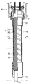
- FIG. 3 is a partial cross-sectional view showing the internal configuration of the bending posture holding portion
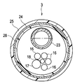
- 4 is a cross-sectional view taken along the line IV-IV in FIG. 3
- FIG. 5 is a perspective view of a surgical endoscope apparatus for explaining the operation of the bending posture holding portion
- FIG. 6 shows the bending posture holding portion of the first modification.
- FIG. 7 is a partial cross-sectional view of the bending posture holding portion of the second modified example on the insertion portion side
- FIG. 8 is an operation unit side of the bending posture holding portion of the second modified example.
- FIG. 9 is a partial sectional view showing the internal configuration of the bending posture holding portion of the third modification
- FIG. 10 is a sectional view taken along the line XX of FIG. 9 of the third modification
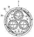
- FIG. 4 is a cross-sectional view of the bending posture holding portion of the fourth modification viewed from the longitudinal direction
- FIG. 12 is a partial cross-sectional view showing the internal configuration of the bending posture holding portion of the fifth modification. .
- a surgical endoscope apparatus (hereinafter simply referred to as an endoscope apparatus) 1 includes a long insertion portion 2 and a bent shape maintaining portion connected to the proximal end of the insertion portion 2.
- a bending posture holding portion 3 an operation portion 4 connected to the proximal end of the bending posture holding portion 3, a light guide connector 5 connected to a light source device which is an external device (not shown), and an external device (not shown) It has mainly a video connector 6 connected to a certain video system center.
- the operation unit 4 and the light guide connector 5 are connected via a flexible cable (also referred to as a universal cord) 5a, and the light guide connector 5 and the video connector 6 connect the electric cable 6a. Connected through.
- a flexible cable also referred to as a universal cord
- the insertion portion 2 is provided with a distal end portion 7 mainly made of a metallic member such as stainless steel, a bending portion 8 that is bent by an operation on the hand side, and a rigid tube portion 9 of a metal tube such as stainless steel in order from the distal end side.
- the insertion portion 2 is a portion to be inserted into the body, and a communication line and a light guide (not shown) are built in and incorporated therein.
- the communication line is inserted from the operation unit 4 through the flexible cable 5a and the light guide connector 5 into the electric cable 6a and arranged up to the video connector 6. Further, the light guide is inserted from the operation unit 4 through the flexible cable 5 a to the light guide connector 5.
- the operation unit 4 is for operating two angle levers 11 for remotely operating the bending unit 8, an engagement lever 12 for switching the fixation / release of the bending state of the bending unit 8, a light source device for an external device, a video system center, and the like.
- Various switches 13 are provided.
- the two angle levers 11 are bending operation means that can operate the bending portion 8 of the insertion portion 2 in four directions, up, down, left, and right.
- the endoscope apparatus 1 configured as described above is a rigid endoscope used for endoscopic surgery or the like in which most of the insertion portion 2 other than the bending portion 8 and the bending posture holding portion 3 are rigid. It is a mirror device. Note that the endoscope apparatus 1 is provided with an imaging unit, an illumination lens unit, and the like (not shown) at the distal end portion 7 of the insertion portion 2, and other components are well known. Omitted.
- the bending posture holding unit 3 that is a bending shape maintaining unit disposed between the insertion unit 2 and the operation unit 4 of the endoscope apparatus 1 will be described in detail below.
- the bending posture holding part 3 has a predetermined length between the insertion part 2 and the operation part 4 and is fitted to the rigid tube part 9 of the insertion part 2 as shown in FIGS.
- a torsion preventing member 24 as a torsion preventing part disposed so as to cover the outer periphery of 23, and a skin disposed so as to cover the outer peripheries of the operation part side base 22, the bending posture holding tube 23 and the twist preventing member 24.
- a certain outer tube 25 is a certain outer tube 25.
- the insertion portion side base 21 and the operation portion side base 22 are fitted to the proximal end portion of the rigid tube portion 9 of the insertion portion 2 or the frame 15 of the operation portion 4 and are fixed by an adhesive or the like here.
- a bent posture holding tube 23 which is a bent shape holding tube, has a round spring 26 as a first spiral tube in which a round wire is wound spirally, and a deformed wire having a triangular cross section is wound around the round spring 26.
- This is a metal tube body having the deformed wire rod tube 27 that is the second spiral tube.
- the bent posture holding tube 23 can maintain a bent state and can hold the bent state in a fixed manner.
- the bending posture holding tube 23 may be any structure that can maintain an arbitrarily bent state. Therefore, even if it is an interlock flexible tube in which a metal strip is bent into a S-shaped cross section and wound spirally. Good.
- the torsion preventing member 24, which is a torsion preventing portion, is a net-like tubular member in which fibers formed from two or more metals or the like intersect and are knitted in a lattice shape.
- the twist preventing member 24 is flexibly bent by the loosening of two fibers in the bending direction having an angle with respect to the longitudinal axis (longitudinal axis). That is, the twist preventing member 24 is flexibly deformed with respect to compression and tension in the longitudinal axis direction.
- the twist preventing member 24 has one fiber pulled in the twist direction around the longitudinal axis (longitudinal axis), but the insertion portion side base 21, the bending posture holding tube 23, and the operation portion side base 22 Since it is covered, the diameter cannot be reduced (thinned), and a predetermined rigidity can be obtained.
- the twist prevention member 24 can be formed thin by using a configuration in which two or more fibers are knitted as described above. Thereby, it leads also to the diameter reduction and weight reduction of the bending attitude holding
- FIG. 1
- the outer tube 25 integrally covers the outer periphery of the torsion preventing member 24 and the outer periphery of the insertion portion side base 21 to the outer periphery of the operation portion side base 22 to ensure the watertightness of the bending posture holding portion 3, so that the outer sheath tube 25 is highly waterproof and flexible. It is the cover member formed from the member.
- the outer tube 25 is made of a flexible soft member made of a polymer material such as fluorine rubber or silicon rubber.
- the outer tube 25 may be a heat-shrinkable tube that shrinks when heat is applied.
- the outer tube 25 may be pin-bonded at both ends covering the outer periphery of the operation portion side base 22 from the insertion portion side base 21 in order to ensure water tightness. Further, the outer tube 25 and the torsion prevention member 24 are bonded and integrated with an adhesive or the like, or the outer tube 25 is welded and integrated on the outer side of the torsion prevention member 24 to be integrated on the outer periphery of the bending posture holding tube 23. It may be arranged.
- the bending section 8 is operated to bend.
- the four operation wires 16 the imaging cable 17 of the imaging unit disposed at the distal end 7, and a light guide that transmits illumination light.
- the bundle 18 is inserted (see FIG. 4).
- the bending posture holding section 3 is covered with the outer tube 25 by covering the bending posture holding tube 23 whose both ends are fixed to the insertion portion side base 21 and the operation portion side base 22 with the twist preventing member 24. It has a configuration.
- the endoscope apparatus 1 configured in this way can freely change the angle of the insertion portion 2 with respect to the operation portion 4 by arbitrarily bending the bending posture holding portion 3 by the user,
- the bent state can be fixed and held by the shape holding force of the bent posture holding tube 23.
- the endoscopic device 1 allows the surgeon and the insertion unit 2 to operate when the scoopist operates the endoscope visual field direction to a predetermined position based on an instruction from the surgeon. Further, the angle of the insertion portion 2 with respect to the operation portion 4 can be arbitrarily changed in a state where the bending posture holding portion 3 is bent and fixed at a position where the operation portion 4 does not interfere with the patient and the operation portion 4. Can do.
- the scopist can change the angle of the insertion unit 2 with respect to the operation unit 4 to a position where it does not interfere with the surgeon, and can hold the operation unit 4 of the endoscope apparatus 1 with an easy posture.
- the endoscope apparatus 1 can be easily operated.
- the scopist makes the vertical direction of the endoscopic image displayed on the monitor coincide with the vertical direction of the treatment portion, so that the visual field shift and image shake from the treatment site are not caused.
- the operation unit 4 can be held in a state where the viewing direction is stabilized.
- the endoscope apparatus 1 has a twist preventing member so as to integrally cover the operation portion side base 22 from the insertion portion side base 21 including the bending posture holding tube 23 in addition to the shape holding force by the bending posture holding portion 3. 24 is provided.
- the endoscope apparatus 1 is prevented from being twisted by the predetermined rigidity with respect to the twisting direction around the longitudinal axis of the torsion preventing member 24. It becomes the composition.
- the endoscope apparatus 1 has a configuration in which the insertion unit 2 is difficult to rotate around the axis with respect to the operation unit 4, and the vertical direction of the endoscopic image displayed on the monitor does not match the vertical direction of the affected part to be treated. Since it is possible to prevent the deviation from occurring, the viewing direction is stabilized. In addition, even when an external force in the twisting direction is applied to the bending posture holding unit 3, the bending posture holding unit 3 is extremely unlikely to be destroyed by having a predetermined rigidity.
- the endoscope apparatus 1 of the present embodiment grasps the endoscope visual field direction in a stable state without causing an uncomfortable posture by a scopist who receives an operation instruction from the surgeon in operation. Can be operated.
- the bending posture holding unit 3 may be provided with a flexible tube body 20 on the inner diameter side of the bending posture holding tube 23 as shown in FIG.
- a flexible tube body 20 By providing the flexible tube body 20, it is possible to prevent the round spring 26 of the bending posture holding tube 23 and the four operation wires 16, the imaging cable 17, or the light guide bundle 18 from interfering with each other.
- the flexible tube body 20 can also seal the metal powder generated by rubbing the metal round spring 26 and the deformed wire rod 27 of the bending posture holding tube 23.
- the bending posture holding unit 3 may be configured such that the internal bending posture holding tube 23 is rotatable. Specifically, as shown in FIG. 7 or FIG. 8, the bending posture holding tube 23 is rotatably held by the insertion portion side base 21 and / or the operation portion side base 22.
- the insertion portion side base 21 is formed with a concave groove portion 21a in which the distal end portion of the bending posture holding tube 23 is engaged in the circumferential direction.
- the bending posture holding tube 23 is rotatable about the longitudinal axis X with respect to the insertion portion side base 21.
- a concave groove portion 22 a into which the proximal end portion of the bending posture holding tube 23 is engaged is formed in the circumferential direction.
- the bending posture holding tube 23 is rotatable about the longitudinal axis X with respect to the operation portion side base 22.
- the bending posture holding section 3 may be configured such that the bending posture holding tube 23 is rotatable with respect to one of the insertion portion side base 21 and the operation portion side base 22, and is at least rotatable with respect to the insertion portion side base 21.
- a configuration is preferable.
- the bending posture holding unit 3 is not twisted around the longitudinal axis X because the bending posture holding tube 23 is rotatable when the bending posture holding unit 3 is arbitrarily bent by a user such as a scoopist.
- the structure prevents deformation and breakage.
- the bending posture holding unit 3 is provided with a flex tube 28 between the twist preventing member 24 and the outer tube 25, and the bending posture holding tube 23 having a reduced diameter inside the flex tube 28. It is good also as a structure which made it penetrate.
- the flex tube 28 is a crush preventing member for preventing the outer tube 25 from being deformed in the inner diameter direction by an external force.
- the flex tube 28 is formed by winding a plate-like member into a spiral shape, but may be a bellows tube.
- the bending posture holding section 3 has a bending posture holding tube 23 arranged at a position eccentric with respect to the center thereof, and is arranged in a space in which the four operation wires 16, the imaging cable 17, and the light guide bundle 18 are vacant. Has been.
- the bending posture holding unit 3 has a high degree of freedom in the layout in which the built-in objects are arranged, and the bending posture holding tube 23 is simply inserted into the flex tube 28.
- the repairability is excellent.
- the bending posture holding section 3 is arranged at a position that is eccentric with respect to the center of the bending posture holding tube 23, thereby further increasing the rigidity in the twist direction combined by the bending posture holding tube 23 and the twist preventing member 24. it can.
- the bending posture holding unit 3 has a configuration in which a plurality of, in this case, three bending posture holding pipes 23 are arranged in the flex pipe 28 as shown in FIG. It is good.
- the bending posture holding unit 3 here has the operation wire 16, the imaging cable 17, and the light guide bundle 18 inserted through each bending posture holding tube 23.
- the bending posture holding section 3 includes a plurality of bending posture holding tubes 23, the torsional rigidity is high, the shape holding force against bending is large, and the bending state can be fixed and held.
- the bending posture holding unit 3 is replaced with a twist preventing member 24, and a distal end bending piece 31, a proximal end bending piece 32, and a plurality of bending pieces 33 which are metal cylinders can be rotated by rivets. It is good also as a structure which connected and provided the bending attitude
- the bending posture holding unit 3 has a distal end bending piece 31 fitted in the insertion portion side base 21 and a proximal end bending piece 32 fitted in and connected to the operation unit side base 22, and a plurality of bending pieces 33.
- the outer tube 25 is covered on the outer periphery of the proximal bending piece 32 from the distal bending piece 31 including
- the bending posture holding unit 3 has a configuration with higher rigidity against twisting due to the rigidity of the plurality of bending pieces 33.
Landscapes
- Health & Medical Sciences (AREA)
- Life Sciences & Earth Sciences (AREA)
- Physics & Mathematics (AREA)
- Surgery (AREA)
- Optics & Photonics (AREA)
- Biomedical Technology (AREA)
- Public Health (AREA)
- Nuclear Medicine, Radiotherapy & Molecular Imaging (AREA)
- Pathology (AREA)
- Radiology & Medical Imaging (AREA)
- Veterinary Medicine (AREA)
- Engineering & Computer Science (AREA)
- Molecular Biology (AREA)
- Biophysics (AREA)
- Medical Informatics (AREA)
- Heart & Thoracic Surgery (AREA)
- Animal Behavior & Ethology (AREA)
- General Health & Medical Sciences (AREA)
- General Physics & Mathematics (AREA)
- Astronomy & Astrophysics (AREA)
- Endoscopes (AREA)
- Instruments For Viewing The Inside Of Hollow Bodies (AREA)
Abstract
外科用内視鏡装置1は、被検体に挿入自在な硬性の挿入部2と、ユーザが把持する操作部4と、挿入部2と操作部4の間に設けられ、ユーザが任意の方向曲げることで、操作部4に対する挿入部2の角度を変更自在にし、その曲げ形状を固定保持する曲げ形状維持部3と、曲げ形状維持部3に設けられ、操作部4に対する挿入部2の長手軸回りの捩じれを防止する捻れ防止部24と、を具備する。
Description
本発明は、撮像装置を備えた内視鏡装置に関し、特に、挿入部が硬質である外科用内視鏡装置に関する。
周知の如く、内視鏡装置は、生体の体内の観察、処置などまたは工業用のプラント設備内の検査、修理などのため広く用いられている。
医療用の内視鏡装置は、生体の上部消化器官、下部消化器官などに挿入される軟性内視鏡装置および腹腔、胸腔などに挿入される外科用の硬性内視鏡装置がある。
また、例えば、日本国特開平7-301751号公報には、軟性内視鏡装置の挿入部に部分的に硬質のスリーブを被せて、用途に応じて、軟性内視鏡装置を生体の腹腔、胸腔などに挿入して内視鏡下外科手術に用いられる硬性内視鏡装置として、使用することができるような技術が開示されている。
ところで、硬性内視鏡装置として外科用内視鏡装置を使用する内視鏡下外科手術においては、外科手術担当医が外科用内視鏡装置を保持するスコピストに内視鏡視野方向を指示して操作させている。
しかしながら、従来の外科用内視鏡装置は、挿入部が硬質であるため、術中に外科手術担当医と患者の体外の挿入部、操作部などが干渉したり、外科手術担当医とスコピストが干渉したり、患者と体外の操作部などが干渉したりするため、スコピストが無理な体勢で操作部を把持して操作しなければならないという問題あった。
さらに、スコピストは、外科手術担当医による患部への処置効率を考え、処置部の天地方向に対してモニタに表示される内視鏡画像の天地方向(上下方向)を一致させて、できるだけ視野方向を安定させて外科用内視鏡装置を保持する必要がある。
しかしながら、スコピストは、無理な体勢で外科用内視鏡装置の操作部を把持した状態であると、処置部位からの視野ズレ、画像揺れを招いてしまい、外科手術担当医による手技に支障を招く虞がある。
そこで、本発明は、上記事情に鑑みて成されたものであって、その目的とするところは、術中に外科手術担当医から操作指示を受けるスコピストなどのユーザが無理な体勢にならずに内視鏡視野方向を安定させた状態で把持して操作できる外科用内視鏡装置を提供することである。
本発明の一態様の外科用内視鏡装置は、被検体に挿入自在な硬性の挿入部と、ユーザが把持する操作部と、前記挿入部と前記操作部の間に設けられ、前記ユーザが任意の方向に曲げることで、前記操作部に対する前記挿入部の角度を変更自在にし、その曲げ形状を固定保持する曲げ形状維持部と、前記曲げ形状維持部に設けられ、前記操作部に対する前記挿入部の長手軸回りの捩じれを防止する捻れ防止部と、を具備する。
上記記載の本発明によれば、術中に外科手術担当医から操作指示を受けるスコピストなどのユーザが無理な体勢にならずに内視鏡視野方向を安定させた状態で把持して操作できる外科用内視鏡装置を提供することができる。
以下、図を用いて本発明について説明する。
なお、以下の説明において、下記の実施の形態に基づく図面は、模式的なものであり、各部分の厚みと幅との関係、夫々の部分の厚みの比率などは現実のものとは異なることに留意すべきであり、図面の相互間においても互いの寸法の関係や比率が異なる部分が含まれている場合がある。
なお、以下の説明において、下記の実施の形態に基づく図面は、模式的なものであり、各部分の厚みと幅との関係、夫々の部分の厚みの比率などは現実のものとは異なることに留意すべきであり、図面の相互間においても互いの寸法の関係や比率が異なる部分が含まれている場合がある。
先ず、本発明の一態様の外科用内視鏡装置の実施の形態について、図面に基づいて、以下に説明する。
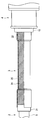
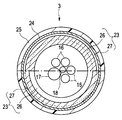
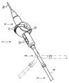
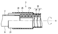
図1は、外科用内視鏡装置の全体構成を示す斜視図、図2は屈曲姿勢保持部の構成を示す部分断面図、図3は屈曲姿勢保持部の内部構成を示す部分断面図、図4は図3のIV-IV線断面図、図5は屈曲姿勢保持部による作用を説明するための外科用内視鏡装置の斜視図、図6は第1の変形例の屈曲姿勢保持部を長手方に対して垂直視の断面図、図7は第2の変形例の屈曲姿勢保持部の挿入部側の部分断面図、図8は第2の変形例の屈曲姿勢保持部の操作部側の部分断面図、図9は第3の変形例の屈曲姿勢保持部の内部構成を示す部分断面図、図10は第3の変形例の図9のX-X線断面図、図11は第4の変形例の屈曲姿勢保持部を長手方に対して垂直視の断面図、図12は第5の変形例の屈曲姿勢保持部の内部構成を示す部分断面図である。
図1は、外科用内視鏡装置の全体構成を示す斜視図、図2は屈曲姿勢保持部の構成を示す部分断面図、図3は屈曲姿勢保持部の内部構成を示す部分断面図、図4は図3のIV-IV線断面図、図5は屈曲姿勢保持部による作用を説明するための外科用内視鏡装置の斜視図、図6は第1の変形例の屈曲姿勢保持部を長手方に対して垂直視の断面図、図7は第2の変形例の屈曲姿勢保持部の挿入部側の部分断面図、図8は第2の変形例の屈曲姿勢保持部の操作部側の部分断面図、図9は第3の変形例の屈曲姿勢保持部の内部構成を示す部分断面図、図10は第3の変形例の図9のX-X線断面図、図11は第4の変形例の屈曲姿勢保持部を長手方に対して垂直視の断面図、図12は第5の変形例の屈曲姿勢保持部の内部構成を示す部分断面図である。
図1に示すように、外科用内視鏡装置(以下、単に内視鏡装置という)1は、長尺な挿入部2と、この挿入部2の基端に連設された曲げ形状維持部である屈曲姿勢保持部3と、この屈曲姿勢保持部3の基端に連設された操作部4と、図示しない外部機器である光源装置に接続するライトガイドコネクタ5と、図示しない外部機器であるビデオシステムセンターに接続するビデオコネクタ6と、を有して主に構成されている。
なお、内視鏡装置1は、操作部4とライトガイドコネクタ5とが軟性ケーブル(ユニバーサルコードともいう)5aを介して接続されており、ライトガイドコネクタ5とビデオコネクタ6とが電気ケーブル6aを介して接続されている。
挿入部2には、主にステンレスなど金属性部材から形成された先端部7、手元側の操作によって湾曲操作される湾曲部8およびステンレスなど金属管の硬性管部9が先端側から順に連設されている。この挿入部2は、体内に挿入する部分となっており、内部に図示しない通信線およびライトガイドなどが内蔵されて組み込まれている。
なお、通信線は、操作部4から軟性ケーブル5aおよびライトガイドコネクタ5を介して電気ケーブル6aに挿通されてビデオコネクタ6まで配設されている。また、ライトガイドは、操作部4から軟性ケーブル5aに挿通されてライトガイドコネクタ5まで配設されている。
操作部4には、湾曲部8を遠隔操作する2つのアングルレバー11、湾曲部8の湾曲状態の固定/解除を切換えるエンゲージレバー12および外部機器の光源装置、ビデオシステムセンターなどを操作するための各種スイッチ13が備えられている。なお、2つのアングルレバー11は、挿入部2の湾曲部8を上下左右の4方向に操作可能な湾曲操作手段である。
以上のように構成された内視鏡装置1は、湾曲部8および屈曲姿勢保持部3以外の大部分の挿入部2が硬質となっている内視鏡下外科手術などに用いられる硬性内視鏡装置である。なお、内視鏡装置1は、挿入部2の先端部7に、図示しない撮像ユニット、照明レンズユニットなどが設けられており、その他構成要素については、周知であるため、それら構成要素の説明を省略する。
ここで、内視鏡装置1の挿入部2と操作部4の間に配設された曲げ形状維持部である屈曲姿勢保持部3について以下に詳しく説明する。
屈曲姿勢保持部3は、挿入部2と操作部4の間で所定の長さを有しており、図2から図4に示すように、挿入部2の硬性管部9に外挿嵌合する管状の挿入部側口金21と、操作部4の先端側に設けられた枠体15に内挿嵌合する管状の操作部側口金22と、これら挿入部側口金21および操作部側口金22の内部に両端部分が内挿嵌合して固定された所謂、スタンドチューブである曲げ形状保持管としての屈曲姿勢保持管23と、挿入部側口金21、操作部側口金22および屈曲姿勢保持管23の外周を覆うように配設された捻れ防止部としての捻れ防止部材24と、操作部側口金22、屈曲姿勢保持管23および捻れ防止部材24の外周を覆うように配設された外皮である外皮チューブ25と、から構成されている。
屈曲姿勢保持部3は、挿入部2と操作部4の間で所定の長さを有しており、図2から図4に示すように、挿入部2の硬性管部9に外挿嵌合する管状の挿入部側口金21と、操作部4の先端側に設けられた枠体15に内挿嵌合する管状の操作部側口金22と、これら挿入部側口金21および操作部側口金22の内部に両端部分が内挿嵌合して固定された所謂、スタンドチューブである曲げ形状保持管としての屈曲姿勢保持管23と、挿入部側口金21、操作部側口金22および屈曲姿勢保持管23の外周を覆うように配設された捻れ防止部としての捻れ防止部材24と、操作部側口金22、屈曲姿勢保持管23および捻れ防止部材24の外周を覆うように配設された外皮である外皮チューブ25と、から構成されている。
挿入部側口金21および操作部側口金22は、挿入部2の硬性管部9の基端部分または操作部4の枠体15に嵌合して、ここでは接着剤などによって固定されている。
曲げ形状保持管である屈曲姿勢保持管23は、螺旋状に丸線材が巻回された第1の螺旋管としての丸バネ26と、この丸バネ26の周囲に断面三角形の異形線材が巻回された第2の螺旋管である異形線材管27と、を有した金属製のチューブ体である。この屈曲姿勢保持管23は、任意に曲げられた状態を維持して、その屈曲状態を固定保持することができるようになっている。
なお、屈曲姿勢保持管23は、任意に曲げられた状態を維持できる構成であればよいため、金属帯材を断面S形状に曲げて螺旋状に巻回させたインターロックフレキシブルチューブであってもよい。
捻れ防止部である捻れ防止部材24は、2本以上の金属などから形成された繊維が交差して格子状に編み込まれた網状の管状部材である。
この捻れ防止部材24は、長手方向の軸(長手軸)に対する角度を有した曲げ方向において、2つの繊維の緩みによって柔軟に曲がるようになっている。即ち、捻れ防止部材24は、長手軸方向の圧縮および引張りに対しては柔軟に変形する。
また、捻れ防止部材24は、長手方向の軸(長手軸)回りの捻れ方向に対して、一方の繊維が引っ張られるが、挿入部側口金21、屈曲姿勢保持管23および操作部側口金22を覆っているため縮径(細径化)できず所定の剛性を得ることができる。
さらに、捻れ防止部材24は、上述したように2本以上の繊維を編み込んだ構成とすることにより肉厚を薄く形成できる。これにより、屈曲姿勢保持部3の細径化および軽量化にも繋がる。
外皮チューブ25は、捻れ防止部材24の外周および挿入部側口金21から操作部側口金22の外周までを一体的に被覆して屈曲姿勢保持部3の水密性を確保するため防水性の高い軟性部材から形成されているカバー部材である。
具体的に、外皮チューブ25は、例えば、フッ素ゴム、シリコンゴムなどの高分子材質で柔軟な軟性部材から形成されている。なお、外皮チューブ25は、熱を加えることで収縮する熱収縮チューブ状のものでもよい。
さらに、外皮チューブ25は、水密確保のため、挿入部側口金21から操作部側口金22の外周を被覆する両端部位が糸巻接着されていてもよい。また、外皮チューブ25と捻れ防止部材24との間を接着剤などによって接着して一体化したり、捻れ防止部材24の外側に外皮チューブ25を溶着して一体化して屈曲姿勢保持管23の外周に配設しても良い。
なお、屈曲姿勢保持部3内には、湾曲部8を湾曲操作する、ここでは4本の操作ワイヤ16、先端部7に配設された撮像ユニットの撮像ケーブル17および照明光を伝送するライトガイドバンドル18が挿通されている(図4参照)。
以上に説明したように屈曲姿勢保持部3は、挿入部側口金21および操作部側口金22に両端が固定された屈曲姿勢保持管23を捻れ防止部材24で覆い、外皮チューブ25によって被覆された構成となっている。
このように構成された内視鏡装置1は、図5に示すように、屈曲姿勢保持部3がユーザによって任意に曲げられることで、操作部4に対する挿入部2の角度を自由に変更でき、屈曲姿勢保持管23による形状保持力で、屈曲状態を固定保持できる構成となっている。
これにより、内視鏡装置1は、内視鏡下外科手術において、外科手術担当医の指示に基づきスコピストが内視鏡視野方向を所定の位置に操作する際、外科手術担当医と挿入部2および操作部4が干渉することなく、且つ患者と操作部4とも干渉しない位置に、屈曲姿勢保持部3を曲げて固定保持した状態で操作部4に対する挿入部2の角度を任意に変更させることができる。
また、スコピストは、自分が外科手術担当医とも干渉しない位置に操作部4に対する挿入部2の角度を変更させると共に、楽な体勢で内視鏡装置1の操作部4を把持することができ、容易に内視鏡装置1の操作ができるようになる。
これにより、スコピストは、処置部の天地方向に対してモニタに表示される内視鏡画像の上下方向を一致させて、処置部位からの視野ずれ、画像揺れを招かないように内視鏡装置1の視野方向を安定させた状態で操作部4を把持することができる。
さらに、内視鏡装置1は、屈曲姿勢保持部3による形状保持力に加えて、屈曲姿勢保持管23を含む挿入部側口金21から操作部側口金22を一体的に覆うように捻れ防止部材24が設けられている。
これにより、内視鏡装置1は、屈曲姿勢保持部3に外力が加えられても、捻れ防止部材24が有する長手軸回りの捻れ方向に対する所定の剛性によって屈曲姿勢保持部3の捻れが防止された構成となっている。
そのため、内視鏡装置1は、操作部4に対して挿入部2が軸回りに回転し難い構成となり、モニタに表示される内視鏡画像の上下方向と処置する患部の天地方向とが不一致となってずれてしまうことも防止できるため、視野方向が安定する。また、屈曲姿勢保持部3に捻れ方向の外力が加わっても、所定の剛性を有することで屈曲姿勢保持部3が破壊されるおそれが極めて低くなる。
以上の説明により、本実施の形態の内視鏡装置1は、術中に外科手術担当医から操作指示を受けるスコピストが無理な体勢にならずに内視鏡視野方向を安定させた状態で把持して操作できる構成となる。
(第1の変形例)
屈曲姿勢保持部3は、図6に示すように、屈曲姿勢保持管23の内径側に軟性チューブ体20を設けても良い。
この軟性チューブ体20を設けることで、屈曲姿勢保持管23の丸バネ26と4本の操作ワイヤ16、撮像ケーブル17またはライトガイドバンドル18が干渉することを防止することができる。
屈曲姿勢保持部3は、図6に示すように、屈曲姿勢保持管23の内径側に軟性チューブ体20を設けても良い。
この軟性チューブ体20を設けることで、屈曲姿勢保持管23の丸バネ26と4本の操作ワイヤ16、撮像ケーブル17またはライトガイドバンドル18が干渉することを防止することができる。
さらに、軟性チューブ体20は、屈曲姿勢保持管23の金属製の丸バネ26および異形線材管27が擦れることで発生する金属粉を封止することもできる。
このように、屈曲姿勢保持管23の内側に軟性チューブ体20を設けることで、屈曲姿勢保持部3内の内蔵物への干渉による損傷、金属粉による擦れなどを防止できるため、内蔵物の耐久性を向上させることができる。
(第2の変形例)
屈曲姿勢保持部3は、内部の屈曲姿勢保持管23が回転自在な構成としてもよい。
具体的には、屈曲姿勢保持管23は、図7または図8に示すように、挿入部側口金21または/および操作部側口金22によって回動保持されている。
屈曲姿勢保持部3は、内部の屈曲姿勢保持管23が回転自在な構成としてもよい。
具体的には、屈曲姿勢保持管23は、図7または図8に示すように、挿入部側口金21または/および操作部側口金22によって回動保持されている。
図7に示す、挿入部側口金21には、屈曲姿勢保持管23の先端部分が係入される凹部状の溝部21aが周方向に形成されている。これにより、屈曲姿勢保持管23は、挿入部側口金21に対して長手軸X回りに回動自在となる。
図8に示す、操作部側口金22には、挿入部側口金21と同様に、屈曲姿勢保持管23の基端部分が係入される凹部状の溝部22aが周方向に形成されている。これにより、屈曲姿勢保持管23は、操作部側口金22に対して長手軸X回りに回動自在となる。
なお、屈曲姿勢保持部3は、屈曲姿勢保持管23が挿入部側口金21または操作部側口金22の一方と回動自在な構成でもよく、少なくとも挿入部側口金21に対して回動自在な構成とすることが好ましい。
このような構成により、屈曲姿勢保持部3は、スコピストなどのユーザの任意で曲げられたときに、内部の屈曲姿勢保持管23が回動自在であるため長手軸X回りの捩じれが生じないため変形、破損などが防止された構成となる。
(第3の変形例)
屈曲姿勢保持部3は、図9および図10に示すように、捻れ防止部材24と外皮チューブ25との間にフレックス管28が設けられ、フレックス管28内に細径化した屈曲姿勢保持管23を挿通させた構成としてもよい。
屈曲姿勢保持部3は、図9および図10に示すように、捻れ防止部材24と外皮チューブ25との間にフレックス管28が設けられ、フレックス管28内に細径化した屈曲姿勢保持管23を挿通させた構成としてもよい。
フレックス管28は、外皮チューブ25が外力によって内径方向に変形しないようにするための潰れ防止部材となっている。なお、ここでのフレックス管28は、板状部材を螺旋状に巻回して筒状に形成したものであるが、蛇腹管としてもよい。
そして、屈曲姿勢保持部3は、その中心に対して偏心した位置に屈曲姿勢保持管23が配置されており、4本の操作ワイヤ16、撮像ケーブル17およびライトガイドバンドル18が空いたスペースに配置されている。
このような構成によって、屈曲姿勢保持部3は、内蔵物を配置するレイアウトの自由度が高くなると共に、フレックス管28内に単に屈曲姿勢保持管23が挿通する構成でるため、屈曲姿勢保持管23の修理性が優れた構成となる。
さらに、屈曲姿勢保持部3は、屈曲姿勢保持管23を中心に対して偏心した位置に配置したことで、屈曲姿勢保持管23と捻れ防止部材24により複合した捻れ方向の剛性を更に高めることができる。
(第4の変形例)
屈曲姿勢保持部3は、上記第3の変形例の構成に加え、図11に示すように、細径化した屈曲姿勢保持管23をフレックス管28内に、複数、ここでは3本配置した構成としてもよい。
屈曲姿勢保持部3は、上記第3の変形例の構成に加え、図11に示すように、細径化した屈曲姿勢保持管23をフレックス管28内に、複数、ここでは3本配置した構成としてもよい。
なお、ここでの屈曲姿勢保持部3は、操作ワイヤ16、撮像ケーブル17およびライトガイドバンドル18を各屈曲姿勢保持管23内に挿通させている。
ここでの屈曲姿勢保持部3は、屈曲姿勢保持管23が複数であるため、捻り剛性も高く、曲げに対する形状保持力が大きく、より屈曲状態を固定保持することができる構成となる。
(第5の変形例)
屈曲姿勢保持部3は、図12に示すように、捻れ防止部材24に変えて、金属筒体である先端湾曲駒31、基端湾曲駒32および複数の湾曲駒33がリベットにより回動自在に連結されており、その内部に屈曲姿勢保持管23を設けた構成としてもよい。
屈曲姿勢保持部3は、図12に示すように、捻れ防止部材24に変えて、金属筒体である先端湾曲駒31、基端湾曲駒32および複数の湾曲駒33がリベットにより回動自在に連結されており、その内部に屈曲姿勢保持管23を設けた構成としてもよい。
なお、屈曲姿勢保持部3は、先端湾曲駒31が挿入部側口金21に内嵌され、基端湾曲駒32が操作部側口金22に内嵌されて接続されており、複数の湾曲駒33を含む先端湾曲駒31から基端湾曲駒32の外周に外皮チューブ25が被覆されている。
このような構成によって、屈曲姿勢保持部3は、複数の湾曲駒33の剛性によって、さらに捻れに対する剛性が高い構成となる。
以上の各実施の形態に記載した発明は、その実施の形態、及び変形例に限ることなく、その他、実施段階ではその要旨を逸脱しない範囲で種々の変形を実施し得ることが可能である。さらに、上記実施の形態には、種々の段階の発明が含まれており、開示される複数の構成要件における適宜な組合せにより種々の発明が抽出され得る。
例えば、実施の形態に示される全構成要件から幾つかの構成要件が削除されても、発明が解決しようとする課題が解決でき、発明の効果で述べられている効果が得られる場合には、この構成要件が削除された構成が発明として抽出され得る。
本出願は、2014年2月25日に日本国に出願された特願2014-034510号を優先権主張の基礎として出願するものであり、上記の内容は、特願2014-034510号の明細書、特許請求の範囲、および図面に引用されたものである。
Claims (7)
- 被検体に挿入自在な硬性の挿入部と、
ユーザが把持する操作部と、
前記挿入部と前記操作部の間に設けられ、前記ユーザが任意の方向に曲げることで、前記操作部に対する前記挿入部の角度を変更自在にし、その曲げ形状を固定保持する曲げ形状維持部と、
前記曲げ形状維持部に設けられ、前記操作部に対する前記挿入部の長手軸回りの捩じれを防止する捻れ防止部と、
を具備することを特徴とする外科用内視鏡装置。 - 前記曲げ形状維持部は、丸線材が巻回して形成された第1の螺旋管と、前記第1の螺旋管の外周に異形線材が巻回して配設された第2の螺旋管と、を備えた曲げ形状保持管を備えていることを特徴とする請求項1に記載の外科用内視鏡装置。
- 前記捻れ防止部材は、複数の繊維を編組して形成された網状管であって、内径方向へ縮径しないように、前記曲げ形状保持管の外周を覆うように配設されていることを特徴とする請求項2に記載の外科用内視鏡装置。
- 前記曲げ形状保持管の前記第1の螺旋管の内周に軟性チューブを配設したことを特徴とする請求項2または請求項3に記載の外科用内視鏡装置。
- 前記軟性チューブ内に内蔵物を配置したことを特徴とする請求項4に記載の外科用内視鏡装置。
- 前記曲げ形状保持管は、前記挿入部または前記操作部の少なくとも一方に対して回動自在に配設されていることを特徴とする請求項2から請求項5のいずれか1項に記載の外科用内視鏡装置。
- 前記曲げ形状維持部は、前記捻れ防止部材の外周を覆って水密保持するカバー部材を備えていることを特徴とする請求項1から請求項6のいずれか1項に記載の外科用内視鏡装置。
Priority Applications (1)
| Application Number | Priority Date | Filing Date | Title |
|---|---|---|---|
| JP2015528736A JP5865559B1 (ja) | 2014-02-25 | 2014-09-19 | 外科用内視鏡装置 |
Applications Claiming Priority (2)
| Application Number | Priority Date | Filing Date | Title |
|---|---|---|---|
| JP2014-034510 | 2014-02-25 | ||
| JP2014034510 | 2014-02-25 |
Publications (1)
| Publication Number | Publication Date |
|---|---|
| WO2015129086A1 true WO2015129086A1 (ja) | 2015-09-03 |
Family
ID=54008434
Family Applications (1)
| Application Number | Title | Priority Date | Filing Date |
|---|---|---|---|
| PCT/JP2014/074911 Ceased WO2015129086A1 (ja) | 2014-02-25 | 2014-09-19 | 外科用内視鏡装置 |
Country Status (2)
| Country | Link |
|---|---|
| JP (1) | JP5865559B1 (ja) |
| WO (1) | WO2015129086A1 (ja) |
Cited By (1)
| Publication number | Priority date | Publication date | Assignee | Title |
|---|---|---|---|---|
| CN109195500A (zh) * | 2016-05-31 | 2019-01-11 | 奥林巴斯株式会社 | 内窥镜的挠性管 |
Citations (8)
| Publication number | Priority date | Publication date | Assignee | Title |
|---|---|---|---|---|
| JPS63122419A (ja) * | 1986-11-11 | 1988-05-26 | 富士写真光機株式会社 | 内視鏡 |
| JPH0655601U (ja) * | 1993-01-13 | 1994-08-02 | オリンパス光学工業株式会社 | 内視鏡用可撓管 |
| JPH0951870A (ja) * | 1995-08-14 | 1997-02-25 | Asahi Optical Co Ltd | 内視鏡の可撓管 |
| JPH0975298A (ja) * | 1995-09-11 | 1997-03-25 | Asahi Optical Co Ltd | 内視鏡の可撓管用網状管 |
| JPH10258031A (ja) * | 1997-03-17 | 1998-09-29 | Fuji Photo Optical Co Ltd | 内視鏡装置 |
| JP2001070238A (ja) * | 1999-09-08 | 2001-03-21 | Olympus Optical Co Ltd | 内視鏡の可撓管 |
| JP2002263059A (ja) * | 2001-03-12 | 2002-09-17 | Asahi Optical Co Ltd | 内視鏡用可撓管 |
| JP2003070717A (ja) * | 2001-09-05 | 2003-03-11 | Olympus Optical Co Ltd | 内視鏡装置 |
-
2014
- 2014-09-19 WO PCT/JP2014/074911 patent/WO2015129086A1/ja not_active Ceased
- 2014-09-19 JP JP2015528736A patent/JP5865559B1/ja active Active
Patent Citations (8)
| Publication number | Priority date | Publication date | Assignee | Title |
|---|---|---|---|---|
| JPS63122419A (ja) * | 1986-11-11 | 1988-05-26 | 富士写真光機株式会社 | 内視鏡 |
| JPH0655601U (ja) * | 1993-01-13 | 1994-08-02 | オリンパス光学工業株式会社 | 内視鏡用可撓管 |
| JPH0951870A (ja) * | 1995-08-14 | 1997-02-25 | Asahi Optical Co Ltd | 内視鏡の可撓管 |
| JPH0975298A (ja) * | 1995-09-11 | 1997-03-25 | Asahi Optical Co Ltd | 内視鏡の可撓管用網状管 |
| JPH10258031A (ja) * | 1997-03-17 | 1998-09-29 | Fuji Photo Optical Co Ltd | 内視鏡装置 |
| JP2001070238A (ja) * | 1999-09-08 | 2001-03-21 | Olympus Optical Co Ltd | 内視鏡の可撓管 |
| JP2002263059A (ja) * | 2001-03-12 | 2002-09-17 | Asahi Optical Co Ltd | 内視鏡用可撓管 |
| JP2003070717A (ja) * | 2001-09-05 | 2003-03-11 | Olympus Optical Co Ltd | 内視鏡装置 |
Cited By (1)
| Publication number | Priority date | Publication date | Assignee | Title |
|---|---|---|---|---|
| CN109195500A (zh) * | 2016-05-31 | 2019-01-11 | 奥林巴斯株式会社 | 内窥镜的挠性管 |
Also Published As
| Publication number | Publication date |
|---|---|
| JPWO2015129086A1 (ja) | 2017-03-30 |
| JP5865559B1 (ja) | 2016-02-17 |
Similar Documents
| Publication | Publication Date | Title |
|---|---|---|
| CN101115432B (zh) | 内窥镜 | |
| JP7220240B2 (ja) | ひずみ緩和要素を備えた操縦可能医用デバイス | |
| CN101106932B (zh) | 内窥镜 | |
| US8133171B2 (en) | Wire spring guide for flexible endoscope | |
| JP6261835B1 (ja) | 内視鏡の可撓管 | |
| EP3138465A1 (en) | Endoscope bending tube and endoscope provided with endoscope bending tube | |
| EP2517615A1 (en) | Tube to be disposed in endoscopes, and endoscope | |
| US20170079505A1 (en) | Endoscope bending portion and endoscope | |
| US20180035870A1 (en) | Endoscope | |
| JP5017714B2 (ja) | Mri用軟性内視鏡 | |
| EP3130304A1 (en) | Treatment tool and surgical system | |
| JP5160798B2 (ja) | 内視鏡及びその湾曲操作用条体並びに内視鏡の製造方法 | |
| JP5865559B1 (ja) | 外科用内視鏡装置 | |
| JP3698844B2 (ja) | 内視鏡 | |
| US10799091B2 (en) | Endoscope with mesh tube | |
| JP2017077348A (ja) | 内視鏡 | |
| JP6257854B2 (ja) | 内視鏡 | |
| JP2018175225A (ja) | 内視鏡システム | |
| KR102794944B1 (ko) | 내시경용 튜브 | |
| US20260126641A1 (en) | Imaging systems with fiber optic light sources | |
| JP4457424B2 (ja) | 内視鏡の軟性部構造 | |
| JP2000296106A (ja) | 内視鏡 | |
| WO2023107476A1 (en) | Imaging systems with fiber optic light sources | |
| JPH0445177B2 (ja) | ||
| JP2003116780A (ja) | 内視鏡 |
Legal Events
| Date | Code | Title | Description |
|---|---|---|---|
| ENP | Entry into the national phase |
Ref document number: 2015528736 Country of ref document: JP Kind code of ref document: A |
|
| 121 | Ep: the epo has been informed by wipo that ep was designated in this application |
Ref document number: 14884202 Country of ref document: EP Kind code of ref document: A1 |
|
| NENP | Non-entry into the national phase |
Ref country code: DE |
|
| 122 | Ep: pct application non-entry in european phase |
Ref document number: 14884202 Country of ref document: EP Kind code of ref document: A1 |