WO2015125663A1 - 反応セル、及び生化学自動分析装置 - Google Patents
反応セル、及び生化学自動分析装置 Download PDFInfo
- Publication number
- WO2015125663A1 WO2015125663A1 PCT/JP2015/053608 JP2015053608W WO2015125663A1 WO 2015125663 A1 WO2015125663 A1 WO 2015125663A1 JP 2015053608 W JP2015053608 W JP 2015053608W WO 2015125663 A1 WO2015125663 A1 WO 2015125663A1
- Authority
- WO
- WIPO (PCT)
- Prior art keywords
- reaction cell
- thickness
- flat plates
- corner
- cell according
- Prior art date
- Legal status (The legal status is an assumption and is not a legal conclusion. Google has not performed a legal analysis and makes no representation as to the accuracy of the status listed.)
- Ceased
Links
Images


Classifications
-
- B—PERFORMING OPERATIONS; TRANSPORTING
- B01—PHYSICAL OR CHEMICAL PROCESSES OR APPARATUS IN GENERAL
- B01L—CHEMICAL OR PHYSICAL LABORATORY APPARATUS FOR GENERAL USE
- B01L3/00—Containers or dishes for laboratory use, e.g. laboratory glassware; Droppers
- B01L3/50—Containers for the purpose of retaining a material to be analysed, e.g. test tubes
- B01L3/508—Containers for the purpose of retaining a material to be analysed, e.g. test tubes rigid containers not provided for above
-
- G—PHYSICS
- G01—MEASURING; TESTING
- G01N—INVESTIGATING OR ANALYSING MATERIALS BY DETERMINING THEIR CHEMICAL OR PHYSICAL PROPERTIES
- G01N21/00—Investigating or analysing materials by the use of optical means, i.e. using sub-millimetre waves, infrared, visible or ultraviolet light
- G01N21/01—Arrangements or apparatus for facilitating the optical investigation
- G01N21/03—Cuvette constructions
-
- G—PHYSICS
- G01—MEASURING; TESTING
- G01N—INVESTIGATING OR ANALYSING MATERIALS BY DETERMINING THEIR CHEMICAL OR PHYSICAL PROPERTIES
- G01N21/00—Investigating or analysing materials by the use of optical means, i.e. using sub-millimetre waves, infrared, visible or ultraviolet light
- G01N21/17—Systems in which incident light is modified in accordance with the properties of the material investigated
- G01N21/25—Colour; Spectral properties, i.e. comparison of effect of material on the light at two or more different wavelengths or wavelength bands
- G01N21/27—Colour; Spectral properties, i.e. comparison of effect of material on the light at two or more different wavelengths or wavelength bands using photo-electric detection ; circuits for computing concentration
-
- G—PHYSICS
- G01—MEASURING; TESTING
- G01N—INVESTIGATING OR ANALYSING MATERIALS BY DETERMINING THEIR CHEMICAL OR PHYSICAL PROPERTIES
- G01N35/00—Automatic analysis not limited to methods or materials provided for in any single one of groups G01N1/00 - G01N33/00; Handling materials therefor
-
- B—PERFORMING OPERATIONS; TRANSPORTING
- B01—PHYSICAL OR CHEMICAL PROCESSES OR APPARATUS IN GENERAL
- B01L—CHEMICAL OR PHYSICAL LABORATORY APPARATUS FOR GENERAL USE
- B01L2200/00—Solutions for specific problems relating to chemical or physical laboratory apparatus
- B01L2200/12—Specific details about manufacturing devices
-
- B—PERFORMING OPERATIONS; TRANSPORTING
- B01—PHYSICAL OR CHEMICAL PROCESSES OR APPARATUS IN GENERAL
- B01L—CHEMICAL OR PHYSICAL LABORATORY APPARATUS FOR GENERAL USE
- B01L2300/00—Additional constructional details
- B01L2300/08—Geometry, shape and general structure
- B01L2300/0848—Specific forms of parts of containers
- B01L2300/0858—Side walls
Definitions
- the present invention relates to a reaction cell used in a biochemical automatic analyzer and a biochemical automatic analyzer using the reaction cell.
- Biochemical automatic analyzer is a device that automatically performs absorption analysis of serum components.
- Absorption analysis of serum components is performed by transmitting light of various wavelengths to a mixture of reagents and reaction with serum, and measuring absorbance at each wavelength, such as carbohydrates, proteins, minerals, etc. present in serum This method is used to estimate the content of each component of the stool and is used for health checkups.
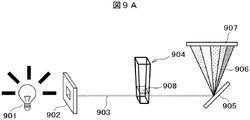
- a schematic diagram of absorption analysis of serum components is shown in FIG. 9A.
- Parallel light (photometric light beam) 903 is extracted by allowing light emitted from the light source 901 to pass through the slit 902 and incident on the mixture 908 of serum and reagent.
- the transmitted light is split by the diffraction grating 905 to obtain a spectrum 906.
- the absorbance at each wavelength is measured by the detection unit 907 from the spectrum, and the content of each component in the serum is estimated.
- reaction cell 904. A container in which serum and a reagent are mixed is called a reaction cell 904.
- the reaction cell 904 desirably has a high transmittance in a band of 100 nm to 1000 nm including visible light. For this reason, an optical material is used as the reaction cell material.
- parallel light is used for transmitted light for the purpose of collecting and analyzing the transmitted light in one place without dispersing it, and the reaction cell is generally a box type that combines flat plates. Shape is taken.
- the amount of serum and reagents required for performing a reliable analysis is several microliters to several tens of microliters, and the size of a general reaction cell is several tens of square mm in cross section and several tens of squares in height. It is about mm.
- the area used for photometry at the time of analysis is limited to a height of several mm from the cell bottom.
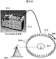
- Biochemical automatic analyzers may be designed as follows from the viewpoint of analyzing a large number of sera at high speed and automatically.
- a reaction cell is arranged on the circumference by a disk or the like, a light source is installed at the center of the circle, and a diffraction grating is installed in the radial direction, and the disk is rotated to measure the alternative reaction cell.
- the reaction cell is basically a consumable product, and high productivity is required to cope with a huge number of daily biochemical tests. For this reason, the reaction cell is molded and manufactured into a box shape by injection molding of optical resin or optical glass. Further, from the viewpoint of improving productivity and reducing costs, a reaction cell (hereinafter referred to as a continuous cell) in which several to several tens of cells are integrally formed may be used. This continuous cell molding is disclosed in Patent Document 1.
- Molding defects include welds and foreign matter. Among these, the weld has solidified unfilled portions and has a micro notch shape. If the weld exists in the light transmitting portion, light scattering occurs in photometry, the analysis efficiency is lowered, and a measurement error may occur in some cases. For this reason, when a weld is recognized in the light transmission part in the inspection after molding, it is excluded from the shipment target as a defective product. In particular, when any one of the above-described continuous cells has a molding defect, the other continuous cells are defective. For this reason, in a continuous cell, the influence which the generation
- an object of the present invention is to provide a reaction cell for a bioanalytical automatic analyzer with high analytical efficiency that prevents the occurrence of welds in a light transmission part, reduces the scattering of transmitted light, and has stable permeability. .
- the occurrence of the weld is determined by the resin filling pattern, and the resin filling pattern is substantially determined by the cavity size and shape. For this reason, it can be said that it is important to design a cavity dimension and shape so that a resin merge is not generated during filling.
- a vent exhaust port of the mold cavity
- a weld is created at a position that does not impair product performance.
- the distance between the cells is as small as several millimeters, and it is difficult to provide a vent for each cell.
- the reaction cell of the present invention has the following characteristics.
- a bottomed reaction cell having an opening at one end, the tube wall of the reaction cell comprising a pair of wall surfaces facing each other and two side wall surfaces connected to each of the pair of wall surfaces via a corner.
- the wall thickness of the set of wall surfaces is thicker than the connecting corner thicknesses, is uniform over the entire wall surface, or has a maximum value in a part of each wall thickness, The wall thickness monotonously decreases from the position having the maximum value to the corner.
- reaction cell for a biochemical automatic analyzer that can prevent generation of welds in a light transmitting portion and obtain stable permeability.
- FIG. 1 is a schematic diagram of a reaction cell shown in Example 1.
- FIG. It is a schematic diagram of a weld production
- 3 is a schematic top view of a reaction cell shown in Example 2.
- FIG. 4 is a schematic top view and cross-sectional view of a reaction cell shown in Example 3.
- FIG. It is a figure which shows the relationship between the thickness of the corner
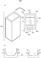
- FIG. 1 is a schematic diagram of the reaction cell of the present invention, where (a) shows an overhead view and (b) shows a schematic top view of the reaction cell shape.
- the reaction cell 100 includes two pairs of flat plates 110 and 120, 130 and 140, a corner portion 150 connecting the flat plates 110 and 130, a corner portion 160 connecting the flat plates 110 and 140, and a corner portion connecting the flat plates 120 and 130. 170, a corner portion 180 connecting the flat plates 120 and 140, and a bottom surface 190.
- the flat plates 110 and 120 are on the short side
- the flat plates 130 and 140 are on the long side.
- the reaction cell 100 has a gate 191 on the back side of the center of the bottom surface 190, the thicknesses of the pair of flat plates 110 and 120 are a1 and a2, respectively, and the maximum of each of the corners 150 to 180 at both ends of the flat plates 110 and 120 is shown.
- the wall thickness is b1 to b4, the following relationship is satisfied.
- a measurement object (for example, serum component) to be analyzed is dropped from the top opening of the overhead view of the reaction cell 100 shown in FIG.
- the reaction cell 100 filled with the measurement object is irradiated with light, the light is transmitted through the flat plates 120 to 110 or 110 to 120 shown in FIG. 1 (b), and the transmittance is detected, whereby the absorption analysis of the measurement object is performed.
- a surface through which light is transmitted is referred to as a light transmitting portion. If welds are generated in the light transmission part, absorption or scattering occurs in part of the transmitted light, and stable transparency cannot be ensured.
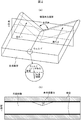
- FIG. 2 shows a schematic diagram of the mechanism of weld formation.
- FIG. 2 shows the flow of the resin being filled in the mold (flows 1 and 2 in the figure).
- (A) is a bird's-eye view which shows the mode of flow of resin
- (b) shows the section of a metallic mold filled with resin in section 1 shown in (a).
- the flow velocity distribution is not uniform, and there are a fast filling portion and a slow filling portion, and resin merging occurs in a slow filling portion.
- the resin solidifies without exhausting gas such as air existing in the cavity in advance at the junction, it remains as a weld on the surface of the molded product.
- the merging angle the opening angle to the resin unfilled portion where air is discharged
- the smaller the merging angle the smaller the air escape space becomes, and the more difficult it is to discharge. Therefore, the smaller the merging angle, the greater the possibility of welds.
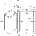
- FIG. 3 shows the conventional shape.
- the conventional reaction cell 300 includes two pairs of flat plates 310 and 320, 330 and 340, a corner portion 350 connecting the flat plates 310 and 330, a corner portion 360 connecting the flat plates 310 and 340, and the flat plates 320 and 330. It comprises a corner portion 370, a corner portion 380 connecting the flat plates 320 and 340, and a bottom surface 390, and has a gate 391 on the center back side of the bottom surface 390.
- the maximum thicknesses b1, b2, b3, and b4 of the corner portions 350 to 380 at both ends thereof were larger than the thicknesses a1 and a2 of the pair of flat plates 310 and 320 that are light transmitting portions. .
- the corner is filled before the light transmitting portion.
- the reason is that the resin preferentially flows into a portion having a small flow resistance.
- the flow resistance is proportional to the cube of the wall thickness, and increases as the wall thickness decreases. For this reason, the filling speed of the light transmitting portion having a small thickness compared with the corner portion is slowed down, and the resin merges at the light transmitting portion.
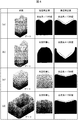
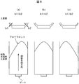
- FIG. 4 (a) is a calculation example in the case where the corner portion is thicker than the light transmitting portion in the conventional reaction cell shown in FIG.
- the resin flowing in from the gate flows preferentially into the corner having a large thickness, and the flow proceeding through the two corners across the flat plate portion has a V shape, and the confluence angle is a short light transmission portion. It is as small as 110 degrees in the side plate portion. For this reason, it can be seen that there is a high possibility of welding when the air is not sufficiently discharged.
- the merging angle is 130 degrees. By comparison with the experiment conducted separately, it was found that when the merging angle in the molding simulation was less than 130 degrees, a weld was generated.
- FIG. 4B shows an example of a result obtained by calculating the resin filling process of the cell shape of the present invention by molding simulation.
- the reaction cell uses a flat plate with a constant thickness on the side surface on the short side in consideration of the parallelism of the transmitted light, but it is difficult to make a flat plate with a strictly constant thickness due to limitations in mold processing accuracy and the like.
- the present invention is effective as long as the variation in thickness depending on the position in the light transmitting portion is within 10 ⁇ m and the thickness of the corner portion is smaller than the thickness of the light transmitting portion including the variation.
- the wall thickness when the parallelism of transmitted light is sacrificed to some extent, it is not always necessary to make the wall thickness constant. In that case, from the above, it has a shape that has a maximum value in a part of the wall thickness of the tube wall of the reaction cell, and the wall thickness monotonously decreases from the position having the maximum value to the corner on the short side. In this case, no confluence occurs when the resin flows into the mold, and no weld is generated.
- the resin merging angle on the long side that is not the light transmitting portion is as small as 100 degrees, and welds are generated. This is thought to be because the thickness of the corner portion was made too thin compared to the flat plate portion of the light transmitting portion. However, since the long side is not a light transmitting portion, the light transmission is not affected even if a weld occurs.
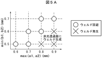
- FIG. 5A shows the shape of the reaction cell and the parameter list used for calculating the result shown in FIG. 5A.
- A is a plan view of a reaction cell
- (b) shows a parameter range (minimum, maximum) regarding the shape used in the calculation
- (c) shows a characteristic range (minimum, maximum) of the resin physical properties in the calculation.
- (D) shows the range of molding conditions (minimum, maximum).
- physical properties such as the viscosity of resin, change with temperature and a shear rate, even if it is the same resin, the range of the value taken during calculation is shown here.
- the light transmission portion does not necessarily have to be on the short side, but here the short side is treated as the light transmission portion.
- FIG. 5A shows whether or not welds occur when the horizontal axis indicates the larger one of the thicknesses a1 and a2 of the flat plates 310 and 320, and the vertical axis indicates the smaller one of the corner thicknesses b1 and b2. It is the figure which prototyped. From FIG. 5A, the long side flat plate portion in the region where the value obtained by subtracting the value on the vertical axis from the value on the horizontal axis is 0.2 mm or less, that is, max (a1, a2) ⁇ min (b1, b2) ⁇ 0.2. It has been found that the occurrence of welds in can also be prevented.
- max (a1, a2) is a function for extracting the maximum value from the variables in parentheses
- min (b1, b2) is a function for extracting the minimum value from the variables in parentheses.
- FIG. 4C shows an example of a calculation result in the same region.
- reaction cell for an automatic biochemical analyzer with high analytical efficiency that prevents the occurrence of welds in the light transmission part, reduces the scattering of transmitted light, and has stable permeability. it can.
- the cell thickness in the flat plates 110 and 120 of the reaction cell shown in FIG. 1 is a constant shape with a square shape at both ends.
- the mold release resistance can be lowered, and the adhesion and retention of bubbles during analysis can be reduced. According to the experiment, the effect was recognized by making the radius of the circle inscribed in the surface shape larger than 0.1 mm.
- the cell is immersed in a temperature-controlled liquid for the purpose of temperature control of serum, but if a bubble is attached to the photometric surface, a measurement error is induced.
- a measurement error is induced.
- it is possible to reduce the adhesion / retention of bubbles, and thus it is possible to prevent the measurement error from being induced.
- FIG. 7 shows another reaction cell shape of the present invention.
- the difference from Example 1 is that the thickness of the corners is kept as before, and a slope is provided on the light transmission part side of the cell bottom.
- the reaction cell 700 includes two pairs of flat plates 710 and 720, and 730 and 740, a corner portion 750 that connects the flat plates 710 and 730, a corner portion 760 that connects the flat plates 710 and 740, and a corner portion that connects the flat plates 720 and 730.
- 770, a corner portion 780 connecting the flat plates 720 and 740, and a bottom surface 790, and a gate 791 is provided at the center rear side of the bottom surface 790.
- the short side thickness d1 and d2 at a certain height from the cell bottom and the long side thickness e1 and e2 at the same height h satisfy the following relationship.
- the resin merging is not seen in the short side flat plate portion which is the light transmitting portion, and the occurrence of welds can be prevented.
- the present embodiment has an effect of avoiding the resin merging in the light transmitting portion only at a certain height from the cell bottom where the gate is located. There is no practical problem.
- This example relates to a biochemical automatic analyzer that automatically performs absorption analysis using any of the reaction cells shown in Examples 1 to 3.
- the biochemical automatic analyzer includes a light source 901 that irradiates light to reaction cells 904 arranged along the periphery of a rotatable disk 910, and a detection unit 907 that detects light that has passed through the reaction cell.
- the reaction cell is filled with a test solution in which a reagent is mixed and reacted with serum, and the reaction cell is irradiated with light having a wavelength of 100 nm to 1000 nm including visible light, and the light is transmitted through the test solution. Let By measuring the absorbance at each wavelength of the transmitted light, the content of each component such as carbohydrate, protein, and mineral present in the serum is estimated.
- welds are not generated at least in the light transmission portion.
- the configuration of the present invention is realized not only in the light transmission part but also in a wide area of the light transmission surface and over the entire light transmission surface. Needless to say, this is more preferable.
Landscapes
- Health & Medical Sciences (AREA)
- Physics & Mathematics (AREA)
- Chemical & Material Sciences (AREA)
- General Health & Medical Sciences (AREA)
- Analytical Chemistry (AREA)
- Immunology (AREA)
- Biochemistry (AREA)
- General Physics & Mathematics (AREA)
- Life Sciences & Earth Sciences (AREA)
- Pathology (AREA)
- Theoretical Computer Science (AREA)
- Mathematical Physics (AREA)
- Engineering & Computer Science (AREA)
- Spectroscopy & Molecular Physics (AREA)
- Hematology (AREA)
- Clinical Laboratory Science (AREA)
- Chemical Kinetics & Catalysis (AREA)
- Optical Measuring Cells (AREA)
- Automatic Analysis And Handling Materials Therefor (AREA)
Priority Applications (3)
| Application Number | Priority Date | Filing Date | Title |
|---|---|---|---|
| EP15752273.1A EP3109617B1 (en) | 2014-02-21 | 2015-02-10 | Reaction cell and biochemical automated analyzer |
| CN201580005932.8A CN106062532A (zh) | 2014-02-21 | 2015-02-10 | 反应单元及生化自动分析装置 |
| US15/115,049 US20160354776A1 (en) | 2014-02-21 | 2015-02-10 | Reaction Cell and Automatic Biochemical Analyzer |
Applications Claiming Priority (2)
| Application Number | Priority Date | Filing Date | Title |
|---|---|---|---|
| JP2014-031886 | 2014-02-21 | ||
| JP2014031886A JP6208596B2 (ja) | 2014-02-21 | 2014-02-21 | 反応セル、及び生化学自動分析装置 |
Publications (1)
| Publication Number | Publication Date |
|---|---|
| WO2015125663A1 true WO2015125663A1 (ja) | 2015-08-27 |
Family
ID=53878169
Family Applications (1)
| Application Number | Title | Priority Date | Filing Date |
|---|---|---|---|
| PCT/JP2015/053608 Ceased WO2015125663A1 (ja) | 2014-02-21 | 2015-02-10 | 反応セル、及び生化学自動分析装置 |
Country Status (5)
| Country | Link |
|---|---|
| US (1) | US20160354776A1 (enExample) |
| EP (1) | EP3109617B1 (enExample) |
| JP (1) | JP6208596B2 (enExample) |
| CN (1) | CN106062532A (enExample) |
| WO (1) | WO2015125663A1 (enExample) |
Cited By (1)
| Publication number | Priority date | Publication date | Assignee | Title |
|---|---|---|---|---|
| US20230228671A1 (en) * | 2019-10-15 | 2023-07-20 | Yep Co.,Ltd. | Rectangular cell for photometric analysis |
Families Citing this family (1)
| Publication number | Priority date | Publication date | Assignee | Title |
|---|---|---|---|---|
| WO2018150944A1 (ja) * | 2017-02-15 | 2018-08-23 | コニカミノルタ株式会社 | 検査チップ及び検査システム |
Citations (5)
| Publication number | Priority date | Publication date | Assignee | Title |
|---|---|---|---|---|
| JPH05133881A (ja) * | 1991-05-07 | 1993-05-28 | F Hoffmann La Roche Ag | 自動アナライザー内で光学測定を行うためのセル |
| JP2003106991A (ja) * | 2001-09-28 | 2003-04-09 | Fuji Photo Optical Co Ltd | 測定チップおよびその作製方法 |
| JP2006349582A (ja) * | 2005-06-17 | 2006-12-28 | Olympus Corp | 攪拌容器及びこの攪拌容器を用いた化学分析装置 |
| JP2007534928A (ja) * | 2003-07-18 | 2007-11-29 | デイド・ベーリング・インコーポレイテッド | 自動臨床アナライザで使用するためのウィッキング防止機能を有する反応キュベット |
| JP2008096115A (ja) * | 2006-10-05 | 2008-04-24 | Sysmex Corp | キュベット |
Family Cites Families (18)
| Publication number | Priority date | Publication date | Assignee | Title |
|---|---|---|---|---|
| DE2702189C2 (de) * | 1977-01-20 | 1985-05-30 | Philips Patentverwaltung Gmbh, 2000 Hamburg | Küvette für die flammenlose Atom- Absorptions-Spektroskopie |
| JPS53157787U (enExample) * | 1977-05-18 | 1978-12-11 | ||
| JPS60166843A (ja) * | 1984-02-09 | 1985-08-30 | Optic:Kk | 液体分析装置用ガラスセルとその製造方法 |
| JPS61247376A (ja) * | 1985-04-26 | 1986-11-04 | Hitachi Ltd | 自動分析装置 |
| DE69012887D1 (de) * | 1989-06-20 | 1994-11-03 | Claudio Bonini | Prüfröhrchen mit einer linsenförmigen Aussenfläche, insbesondere für automatische klinische Analysen. |
| DE4223840C2 (de) * | 1992-07-20 | 1994-06-16 | Zeiss Carl Jena Gmbh | Refraktometer |
| US6387030B1 (en) * | 2000-06-30 | 2002-05-14 | Beckman Coulter, Inc. | Internal adapter with a pellet well for a centrifuge container |
| US7300055B2 (en) * | 2003-04-17 | 2007-11-27 | Kyocera Mita Corporation | Image forming apparatus |
| KR101260400B1 (ko) * | 2005-04-01 | 2013-05-09 | 미쓰비시 가가쿠 메디엔스 가부시키가이샤 | 생체샘플의 복합자동분석장치, 자동분석방법 및 반응 큐벳 |
| EP1909094B1 (en) * | 2005-07-27 | 2017-05-03 | Sysmex Corporation | Cuvette |
| CN201156031Y (zh) * | 2008-02-02 | 2008-11-26 | 施慧勇 | 生化分析仪比色杯 |
| JP5821842B2 (ja) * | 2010-04-09 | 2015-11-24 | 日本電気株式会社 | Webコンテンツ変換装置、Webコンテンツ変換方法およびプログラム |
| EP2466291B1 (en) * | 2010-12-15 | 2013-09-11 | F. Hoffmann-La Roche AG | Cuvette for photometric measurement of small liquid volumes |
| US20120196271A1 (en) * | 2011-01-27 | 2012-08-02 | Pocared Diagnostics Ltd. | Iris Control System for Conducting the Identification of Bacteria in Biological Samples |
| JP2013076622A (ja) * | 2011-09-30 | 2013-04-25 | Hitachi High-Tech Manufacturing & Service Corp | 分析装置用の連セル構造体 |
| CN202994646U (zh) * | 2012-12-27 | 2013-06-12 | 深圳雷杜生命科学股份有限公司 | 便于机械手夹持传送的反应杯 |
| US9902927B2 (en) * | 2013-09-30 | 2018-02-27 | Flextank International Limited | Fluid container assembly with corner reinforcing posts |
| WO2015042651A1 (en) * | 2013-09-30 | 2015-04-02 | Flextank International Limited | Closure assembly |
-
2014
- 2014-02-21 JP JP2014031886A patent/JP6208596B2/ja active Active
-
2015
- 2015-02-10 US US15/115,049 patent/US20160354776A1/en not_active Abandoned
- 2015-02-10 EP EP15752273.1A patent/EP3109617B1/en active Active
- 2015-02-10 WO PCT/JP2015/053608 patent/WO2015125663A1/ja not_active Ceased
- 2015-02-10 CN CN201580005932.8A patent/CN106062532A/zh active Pending
Patent Citations (5)
| Publication number | Priority date | Publication date | Assignee | Title |
|---|---|---|---|---|
| JPH05133881A (ja) * | 1991-05-07 | 1993-05-28 | F Hoffmann La Roche Ag | 自動アナライザー内で光学測定を行うためのセル |
| JP2003106991A (ja) * | 2001-09-28 | 2003-04-09 | Fuji Photo Optical Co Ltd | 測定チップおよびその作製方法 |
| JP2007534928A (ja) * | 2003-07-18 | 2007-11-29 | デイド・ベーリング・インコーポレイテッド | 自動臨床アナライザで使用するためのウィッキング防止機能を有する反応キュベット |
| JP2006349582A (ja) * | 2005-06-17 | 2006-12-28 | Olympus Corp | 攪拌容器及びこの攪拌容器を用いた化学分析装置 |
| JP2008096115A (ja) * | 2006-10-05 | 2008-04-24 | Sysmex Corp | キュベット |
Non-Patent Citations (1)
| Title |
|---|
| See also references of EP3109617A4 * |
Cited By (1)
| Publication number | Priority date | Publication date | Assignee | Title |
|---|---|---|---|---|
| US20230228671A1 (en) * | 2019-10-15 | 2023-07-20 | Yep Co.,Ltd. | Rectangular cell for photometric analysis |
Also Published As
| Publication number | Publication date |
|---|---|
| US20160354776A1 (en) | 2016-12-08 |
| EP3109617B1 (en) | 2022-10-19 |
| JP2015158374A (ja) | 2015-09-03 |
| EP3109617A4 (en) | 2017-10-04 |
| JP6208596B2 (ja) | 2017-10-04 |
| EP3109617A1 (en) | 2016-12-28 |
| CN106062532A (zh) | 2016-10-26 |
Similar Documents
| Publication | Publication Date | Title |
|---|---|---|
| JP5350810B2 (ja) | 自動分析装置及び自動分析方法 | |
| US8994940B2 (en) | Fine particle measurement apparatus and optical axis calibration method | |
| US8976353B2 (en) | Multiwell plate lid for improved optical measurements | |
| US20150160251A1 (en) | Automatic Analysis Apparatus and Sample Measuring Method | |
| CN104471381B (zh) | 自动分析装置以及自动分析方法 | |
| US9080972B2 (en) | Automatic analyzer | |
| JP2011107032A (ja) | 表面プラズモン共鳴チップ | |
| CN107912055A (zh) | 用于测量液体体积的装置和方法 | |
| JP5442447B2 (ja) | 試料の分析方法およびその装置 | |
| JP6208596B2 (ja) | 反応セル、及び生化学自動分析装置 | |
| US7889337B2 (en) | Optical method for determination of the total suspended solids in jet fuel | |
| CN105092426B (zh) | 纳米颗粒90度散射光谱的测量方法 | |
| JP4895109B2 (ja) | 形状検査方法及び形状検査装置 | |
| CN104390939A (zh) | 一种用于检测微流体系统中液体折射率的传感器及方法 | |
| CN102128809B (zh) | 表面等离子共振传感器芯片组件及柱面棱镜芯片 | |
| JP4308231B2 (ja) | 測光による面内検出 | |
| US12222244B2 (en) | Cavity for gas measurements | |
| EP3484686B1 (en) | Sample vessel having opaque and translucent portions, and sample analyzer system with such a sample vessel | |
| US12265019B2 (en) | Compact imaging-based sensors | |
| EP2378274B1 (en) | Surface plasmon resonance measuring apparatus | |
| KR101996899B1 (ko) | 광산란형 먼지 센서 교정 방법 | |
| CN219608734U (zh) | 带压多探头浊度传感器 | |
| JP7097175B2 (ja) | 粒子物性測定用セル及びこれを用いた粒子物性測定装置 | |
| RU2772562C1 (ru) | Реакционный сосуд для автоматического анализатора | |
| CN109855726A (zh) | 一种免疫散射比浊法的光源功率的校准装置及方法 |
Legal Events
| Date | Code | Title | Description |
|---|---|---|---|
| 121 | Ep: the epo has been informed by wipo that ep was designated in this application |
Ref document number: 15752273 Country of ref document: EP Kind code of ref document: A1 |
|
| REEP | Request for entry into the european phase |
Ref document number: 2015752273 Country of ref document: EP |
|
| WWE | Wipo information: entry into national phase |
Ref document number: 2015752273 Country of ref document: EP |
|
| WWE | Wipo information: entry into national phase |
Ref document number: 15115049 Country of ref document: US |
|
| NENP | Non-entry into the national phase |
Ref country code: DE |