WO2015121926A1 - Module de batterie - Google Patents
Module de batterie Download PDFInfo
- Publication number
- WO2015121926A1 WO2015121926A1 PCT/JP2014/053202 JP2014053202W WO2015121926A1 WO 2015121926 A1 WO2015121926 A1 WO 2015121926A1 JP 2014053202 W JP2014053202 W JP 2014053202W WO 2015121926 A1 WO2015121926 A1 WO 2015121926A1
- Authority
- WO
- WIPO (PCT)
- Prior art keywords
- stacking direction
- along
- battery module
- reinforcing member
- case
- Prior art date
Links
Images

Classifications
-
- H—ELECTRICITY
- H01—ELECTRIC ELEMENTS
- H01M—PROCESSES OR MEANS, e.g. BATTERIES, FOR THE DIRECT CONVERSION OF CHEMICAL ENERGY INTO ELECTRICAL ENERGY
- H01M10/00—Secondary cells; Manufacture thereof
- H01M10/04—Construction or manufacture in general
- H01M10/0481—Compression means other than compression means for stacks of electrodes and separators
-
- H—ELECTRICITY
- H01—ELECTRIC ELEMENTS
- H01M—PROCESSES OR MEANS, e.g. BATTERIES, FOR THE DIRECT CONVERSION OF CHEMICAL ENERGY INTO ELECTRICAL ENERGY
- H01M10/00—Secondary cells; Manufacture thereof
- H01M10/04—Construction or manufacture in general
- H01M10/0413—Large-sized flat cells or batteries for motive or stationary systems with plate-like electrodes
-
- H—ELECTRICITY
- H01—ELECTRIC ELEMENTS
- H01M—PROCESSES OR MEANS, e.g. BATTERIES, FOR THE DIRECT CONVERSION OF CHEMICAL ENERGY INTO ELECTRICAL ENERGY
- H01M10/00—Secondary cells; Manufacture thereof
- H01M10/04—Construction or manufacture in general
- H01M10/0436—Small-sized flat cells or batteries for portable equipment
-
- H—ELECTRICITY
- H01—ELECTRIC ELEMENTS
- H01M—PROCESSES OR MEANS, e.g. BATTERIES, FOR THE DIRECT CONVERSION OF CHEMICAL ENERGY INTO ELECTRICAL ENERGY
- H01M10/00—Secondary cells; Manufacture thereof
- H01M10/05—Accumulators with non-aqueous electrolyte
- H01M10/052—Li-accumulators
-
- H—ELECTRICITY
- H01—ELECTRIC ELEMENTS
- H01M—PROCESSES OR MEANS, e.g. BATTERIES, FOR THE DIRECT CONVERSION OF CHEMICAL ENERGY INTO ELECTRICAL ENERGY
- H01M10/00—Secondary cells; Manufacture thereof
- H01M10/05—Accumulators with non-aqueous electrolyte
- H01M10/058—Construction or manufacture
- H01M10/0585—Construction or manufacture of accumulators having only flat construction elements, i.e. flat positive electrodes, flat negative electrodes and flat separators
-
- H—ELECTRICITY
- H01—ELECTRIC ELEMENTS
- H01M—PROCESSES OR MEANS, e.g. BATTERIES, FOR THE DIRECT CONVERSION OF CHEMICAL ENERGY INTO ELECTRICAL ENERGY
- H01M2200/00—Safety devices for primary or secondary batteries
-
- H—ELECTRICITY
- H01—ELECTRIC ELEMENTS
- H01M—PROCESSES OR MEANS, e.g. BATTERIES, FOR THE DIRECT CONVERSION OF CHEMICAL ENERGY INTO ELECTRICAL ENERGY
- H01M2220/00—Batteries for particular applications
- H01M2220/20—Batteries in motive systems, e.g. vehicle, ship, plane
-
- H—ELECTRICITY
- H01—ELECTRIC ELEMENTS
- H01M—PROCESSES OR MEANS, e.g. BATTERIES, FOR THE DIRECT CONVERSION OF CHEMICAL ENERGY INTO ELECTRICAL ENERGY
- H01M50/00—Constructional details or processes of manufacture of the non-active parts of electrochemical cells other than fuel cells, e.g. hybrid cells
- H01M50/20—Mountings; Secondary casings or frames; Racks, modules or packs; Suspension devices; Shock absorbers; Transport or carrying devices; Holders
- H01M50/204—Racks, modules or packs for multiple batteries or multiple cells
- H01M50/207—Racks, modules or packs for multiple batteries or multiple cells characterised by their shape
- H01M50/211—Racks, modules or packs for multiple batteries or multiple cells characterised by their shape adapted for pouch cells
-
- H—ELECTRICITY
- H01—ELECTRIC ELEMENTS
- H01M—PROCESSES OR MEANS, e.g. BATTERIES, FOR THE DIRECT CONVERSION OF CHEMICAL ENERGY INTO ELECTRICAL ENERGY
- H01M50/00—Constructional details or processes of manufacture of the non-active parts of electrochemical cells other than fuel cells, e.g. hybrid cells
- H01M50/50—Current conducting connections for cells or batteries
- H01M50/572—Means for preventing undesired use or discharge
- H01M50/584—Means for preventing undesired use or discharge for preventing incorrect connections inside or outside the batteries
- H01M50/586—Means for preventing undesired use or discharge for preventing incorrect connections inside or outside the batteries inside the batteries, e.g. incorrect connections of electrodes
-
- Y—GENERAL TAGGING OF NEW TECHNOLOGICAL DEVELOPMENTS; GENERAL TAGGING OF CROSS-SECTIONAL TECHNOLOGIES SPANNING OVER SEVERAL SECTIONS OF THE IPC; TECHNICAL SUBJECTS COVERED BY FORMER USPC CROSS-REFERENCE ART COLLECTIONS [XRACs] AND DIGESTS
- Y02—TECHNOLOGIES OR APPLICATIONS FOR MITIGATION OR ADAPTATION AGAINST CLIMATE CHANGE
- Y02E—REDUCTION OF GREENHOUSE GAS [GHG] EMISSIONS, RELATED TO ENERGY GENERATION, TRANSMISSION OR DISTRIBUTION
- Y02E60/00—Enabling technologies; Technologies with a potential or indirect contribution to GHG emissions mitigation
- Y02E60/10—Energy storage using batteries
-
- Y—GENERAL TAGGING OF NEW TECHNOLOGICAL DEVELOPMENTS; GENERAL TAGGING OF CROSS-SECTIONAL TECHNOLOGIES SPANNING OVER SEVERAL SECTIONS OF THE IPC; TECHNICAL SUBJECTS COVERED BY FORMER USPC CROSS-REFERENCE ART COLLECTIONS [XRACs] AND DIGESTS
- Y02—TECHNOLOGIES OR APPLICATIONS FOR MITIGATION OR ADAPTATION AGAINST CLIMATE CHANGE
- Y02P—CLIMATE CHANGE MITIGATION TECHNOLOGIES IN THE PRODUCTION OR PROCESSING OF GOODS
- Y02P70/00—Climate change mitigation technologies in the production process for final industrial or consumer products
- Y02P70/50—Manufacturing or production processes characterised by the final manufactured product
Definitions
- the present invention relates to a battery module.
- the present invention has been made to solve the above-described problems, and an object of the present invention is to provide a battery module capable of improving the rigidity of the case while sufficiently pressing the unit cell.
- the battery module according to the present invention that achieves the above object has a unit cell and a casing.
- the unit cell includes a power generation element and an exterior material.
- the power generation element is formed by laminating a positive electrode and a negative electrode via a separator.
- the exterior material seals the power generation element.
- the housing includes a pair of cases and a reinforcing member.
- the pair of cases sandwich the unit cell from both sides in the stacking direction.
- the reinforcing member is formed in a plate shape and is joined to at least one case of the pair to reinforce the case.
- at least one case of the pair includes a bulging portion, a first extending portion, an inclined portion, and a second extending portion.
- the bulging portion is formed to be curved so as to protrude toward the unit cell, and presses the unit cell.
- the 1st extension part is extended and formed along the direction which cross
- the inclined portion extends from the outer peripheral edge of the first extending portion while being refracted or bent toward the unit cell.
- the second extending portion extends along the direction intersecting the stacking direction from the outer peripheral edge of the inclined portion, and is joined to the reinforcing member.
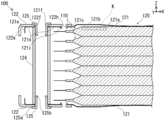
- FIG. 2 is an end view showing the battery module of FIG. 1, with reference to line 2-2 in FIG. 1.
- FIG. 3 is an end view showing a main part of the unit cell arranged in the battery module of FIG. 2, and shows a region K in FIG. 2. It is a perspective view which shows the principal part of the battery module of 2nd Embodiment.
- FIGS. 1 to 4 the azimuth is indicated by using arrows represented by X, Y, and Z.
- the direction of the arrow represented by Z is the stacking direction of the unit cells 110.
- the direction of the arrow represented by X is a direction intersecting with the stacking direction Z of the unit cells 110.
- the X direction corresponds to the longitudinal direction of the unit cell 110.
- the direction of the arrow represented by Y is a direction that intersects the stacking direction Z of the unit cells 110 and intersects the X direction.
- the Y direction corresponds to the short direction of the unit cell 110.
- the battery module 100 is configured by housing a plurality of single cells 110 in a housing 120.
- the battery module 100 is disposed in an automobile and supplies power to a motor provided in the automobile.
- the configuration of the battery module 100 will be described with reference to FIGS.
- FIG. 1 is a perspective view showing the battery module 100.
- FIG. 2 is an end view showing the battery module 100 of FIG.
- FIG. 2 shows the line 2-2 in FIG. 1 as a reference.
- FIG. 3 is an end view showing a main part of the unit cell 110 arranged in the battery module 100 of FIG.
- FIG. 3 shows a region K in FIG.
- the battery module 100 has a single battery 110 and a housing 120. Hereinafter, the configuration of the battery module 100 will be described.
- the unit cell 110 includes a power generation element 10 and an exterior material (laminate sheet 20).
- the power generation element 10 is formed by laminating a positive electrode 11 and a negative electrode 12 with a separator 13 interposed therebetween. Even if the end of the positive electrode 11 and the end of the negative electrode 12 face each other due to the displacement of the constituent members of the power generation element 10, the insulating member 14 is electrically short-circuited between the positive electrode 11 and the negative electrode 12. To prevent.
- the laminate sheet 20 seals the power generation element 10.
- the positive electrode 11, the negative electrode 12, the separator 13, the insulating member 14, and the laminate sheet 20 that constitute the unit cell 110 will be described in order.
- the positive electrode 11 corresponds to an electrode on the anode side. As shown in FIG. 3, the positive electrode 11 is configured by binding a positive electrode active material 11 b to both surfaces of a positive electrode current collector 11 a that is conductive and formed in a plate shape.
- the positive electrode terminal for taking out electric power is formed to extend in the longitudinal direction (X direction) from a part of one end of the positive electrode current collector 11a.
- a plurality of the positive electrode terminals of the positive electrode 11 stacked together are fixed to each other by welding or adhesion.
- the material of the positive electrode current collector 11a for example, an aluminum expanded metal, an aluminum mesh, or an aluminum punched metal is used.
- the material of the positive electrode active material 11b includes various oxides (lithium manganese oxide such as LiMn 2 O 4 ; manganese dioxide; lithium nickel oxide such as LiNiO 2 ; lithium cobalt oxide such as LiCoO 2 ; lithium Containing nickel cobalt oxide; amorphous vanadium pentoxide containing lithium) or chalcogen compound (titanium disulfide or molybdenum disulfide).
- the negative electrode 12 corresponds to an electrode on the cathode side. As shown in FIG. 3, the negative electrode 12 is configured by binding a negative electrode active material 12 b to both surfaces of a negative electrode current collector 12 a having conductivity and formed in a plate shape.
- the negative electrode terminal is formed to extend in a longitudinal direction (X direction) from a part of one end of the negative electrode current collector 12 a so as not to overlap with the positive electrode terminal formed on the positive electrode 11.
- the length of the negative electrode 12 in the longitudinal direction (X direction) is longer than the length of the positive electrode 11 in the longitudinal direction (X direction).
- the length of the negative electrode 12 in the short direction (Y direction) is the same as the length of the positive electrode 11 in the short direction (Y direction).
- a plurality of negative electrode terminals of the negative electrode 12 laminated together are fixed to each other by welding or adhesion.
- the material of the negative electrode current collector 12a for example, a copper expanded metal, a copper mesh, or a copper punched metal is used.
- a carbon material that absorbs and releases lithium ions is used.
- carbon materials for example, natural graphite, artificial graphite, carbon black, activated carbon, carbon fiber, coke, or organic precursor (phenol resin, polyacrylonitrile, or cellulose) is heat-treated in an inert atmosphere and synthesized. Carbon is used.
- the separator 13 electrically isolates the positive electrode 11 and the negative electrode 12. As shown in FIG. 3, the separator 13 is formed in a rectangular shape and disposed between the positive electrode 11 and the negative electrode 12. The length in the longitudinal direction (X direction) of the separator 13 is longer than the length in the longitudinal direction (X direction) of the positive electrode 11 excluding the positive electrode terminal portion. The separator 13 holds an electrolytic solution between the positive electrode 11 and the negative electrode 12 to ensure ion conductivity.
- the material of the separator 13 is, for example, polypropylene.
- Polypropylene is impregnated with a non-aqueous electrolyte prepared by dissolving an electrolyte in a non-aqueous solvent.
- a polymer is included in order to hold the non-aqueous electrolyte.
- the insulating member 14 is electrically short-circuited when the end of the positive electrode 11 and the end of the negative electrode 12 face each other due to the displacement of the separator 13, the positive electrode 11, or the like. To prevent that.
- the insulating member 14 is formed in a thin plate shape having insulating properties, and is laminated and bonded to both ends of the positive electrode 11 in the laminating direction Z.
- the insulating member 14 may be laminated and bonded to the end portion of the negative electrode 12.
- the laminate sheet 20 covers and seals the power generating element 10 from both sides along the stacking direction Z.
- the laminate sheet 20 is composed of a rectangular sheet in which a metal plate is embedded.
- a part of the periphery of the laminate sheet 20 is opened and the other periphery is sealed by heat welding.
- an electrolytic solution is injected into the laminate sheet 20 from the open portion, and the separator 13 or the like is impregnated with the electrolytic solution.
- the inside of the laminate sheet 20 is decompressed to release air from the open portion, and the open portion is heat-sealed to be completely sealed.
- the material of the laminate sheet 20 for example, three kinds of materials stacked on each other are used. Specifically, for example, polyethylene (PE), ionomer, or ethylene vinyl acetate (EVA) is used as the material of the first layer of the heat-fusible resin adjacent to the negative electrode 12.
- PE polyethylene
- EVA ethylene vinyl acetate
- the second layer metal foil for example, an Al foil or a Ni foil is used.
- rigid polyethylene terephthalate (PET) or nylon is used for the third layer resin film.
- the housing 120 integrally stores a plurality of single cells 110. As shown in FIGS. 1 and 2, the pair of cases 121 sandwich the plurality of unit cells 110 from both sides in the stacking direction Z.
- the reinforcing members 122 and 123 are reinforced by joining the pair of cases 121.
- the sleeve 124, the eyelet 125, the first side plate 126, the second side plate 127, the conductive member 128, and the bus bar 129 will be described in order.
- the case 121 is composed of a pair as shown in FIG. 2 and sandwiches the unit cell 110 from both sides in the stacking direction Z.
- the case 121 is formed in a thin plate shape and includes a bulging portion 121a at the center.
- the case 121 is formed by integrally forming the first extending portion 121b, the inclined portion 121c, and the second extending portion 121d in this order from the bulging portion 121a toward both ends along the X direction. Yes.
- the case 121 is integrated with the first extending portion 121b, the inclined portion 121c, and the second extending portion 121d in this order from the bulging portion 121a toward both ends along the Y direction. Forming.
- the second extending portions 121 d at both ends along the Y direction of the case 121 are shorter than the second extending portions 121 d at both ends along the X direction of the case 121.
- the case 121 may be formed integrally with at least the first extending portion 121b from the bulging portion 121a toward both end portions along the Y direction.
- the bulging part 121 a of the case 121 is formed to be curved so as to protrude toward the unit cell 110, and presses the unit cell 110.
- the first extending portion 121b extends from the outer peripheral edge of the bulging portion 121a along the X direction that intersects the stacking direction Z.
- the inclined portion 121c extends from the outer peripheral edge of the first extending portion 121b while being refracted or bent toward the unit cell 110.
- the second extending portion 121d extends along the X direction intersecting the stacking direction Z from the outer peripheral edge of the inclined portion 121c, and is joined to the reinforcing member 122 or 123.
- the inclined portion 121c of the case 121 supports the bulging portion 121a in a deformable manner via the first extending portion 121b while being supported by the reinforcing member 122 or 123 connected to the second extending portion 121d. . That is, the bulging portion 121a is provided with elastic force by the first extending portion 121b, the inclined portion 121c, and the second extending portion 121d, and the portion of the power generation element 10 of the unit cell 110 is removed according to the gas pressure. Press from the side.
- the second extending portion 121 d of the case 121 has an end portion 121 e extending along the X direction and the Y direction intersecting the stacking direction Z in an L shape along the stacking direction Z. It is formed by refraction.
- the second extending portion 121 d includes through holes 121 f penetrating along the stacking direction Z at both ends in the Y direction.
- the through-hole 121f of the case 121 communicates with the through-hole 122f of the reinforcing member 122, for example, and the eyelet 125 that fixes the sleeve 124 is inserted therethrough.
- the second extending portion 121d includes a plurality of fitting holes 121i that are penetrated along the stacking direction Z at regular intervals in the Y direction.
- the fitting hole 121i allows the protrusion 122h of the reinforcing member 122 to be inserted, for example.
- the reinforcing members 122 and 123 reinforce the case 121 as shown in FIG.
- the reinforcing members 122 and 123 are formed in a plate shape, and are respectively joined to the second extending portions 121d at both ends along the X direction of the case 121.
- the reinforcing members 122 and 123 have higher rigidity than the case 121.
- the reinforcing member 122 has a longer width in the X direction than the reinforcing member 123.
- the reinforcing member 122 is disposed on the conductive member 128 side connected to the unit cell 110.
- the reinforcing members 122 and 123 are joined to the second extending portions 121d at both ends along the X direction of the case 121.
- only the reinforcing member 122 may be joined to the second extending portion 121d at one end along the X direction of the case 121.
- the reinforcing members 122 and 123 are joined in a state where at least a part thereof is adjacent to the second extending portion 121d along the stacking direction Z. That is, the reinforcing members 122 and 123 overlap the second extending portion 121d along the stacking direction Z.
- the reinforcing members 122 and 123 have a thickness along the stacking direction Z that is thinner than a thickness along the stacking direction Z of the inclined portion 121c. That is, the reinforcing members 122 and 123 do not protrude in the stacking direction Z with respect to the first extending portion 121 b of the case 121.
- the reinforcing members 122 and 123 are provided with flange portions at the end portions extending along the direction intersecting the stacking direction Z so as to be separated from the second extending portion 121d.
- the flange portion 122a of the reinforcing member 122 is formed by refracting the end portion along the X direction of the reinforcing member 122 along the stacking direction Z, as shown in FIG. Since the flange portion 122a is refracted in an L shape, it is easy to maintain its shape by suppressing deformation when stress is applied from the outside.
- the flange portion 122a restrains the unit cell 110 from moving in the X direction or the Y direction by mooring the unit cell 110.
- the reinforcing members 122 and 123 have through holes penetrating along the stacking direction Z at both ends along the Y direction.
- the through hole 122 f of the reinforcing member 122 communicates with the through hole 121 f of the case 121, and the eyelet 125 that fixes the sleeve 124 is inserted therethrough.
- the reinforcing member 122 includes a plurality of protrusions 122h that protrude along the stacking direction Z at regular intervals in the Y direction. The protrusion 122h is fitted in the fitting hole 121i of the case 121.
- the sleeve 124 corresponds to a holding member. As shown in FIG. 2, the sleeve 124 is inserted between the pair of cases 121 to keep the distance between the pair of cases 121 constant.
- the sleeve 124 is made of, for example, a hard metal and has a long cylindrical shape.
- the sleeve 124 is disposed so as to communicate with through holes 121 f provided at the four corners of the case 121.
- the sleeves 124 are disposed at the four corners of the pair of cases 121 to protect the unit cells 110 stacked between the pair of cases 121 from distortion due to external force.
- the eyelet 125 corresponds to a fixing member. As shown in FIG. 2, the eyelet 125 is press-fitted into the sleeve 124 while being inserted through, for example, the through hole 122 f of the reinforcing member 122 and the through hole 121 f of the case 121, and is deformed and pressure-bonded to the sleeve 124.
- the eyelet 125 is made of, for example, a soft metal and has a short cylindrical shape.
- the eyelet 125 is formed in a cylindrical shape extending in the stacking direction Z while projecting one end 125a of the opening in a direction crossing the stacking direction Z.
- the eyelet 125 has the other end 125 b of the opening inserted into, for example, the through hole 122 f of the reinforcing member 122 and the through hole 121 f of the case 121, and the one end 125 a of the opening is moored to the reinforcing member 122.
- the eyelets 125 are inserted and fixed to the opposite ends along the stacking direction Z in each sleeve 124 provided at the four corners of the case 121. In this way, the eyelet 125 fixes the second extending portion 121d at one end along the X direction of the reinforcing member 122 and the case 121, and the other end of the reinforcing member 123 and the case 121 along the X direction.
- the second extending part 121d is fixed.
- 1st side board 126 consists of a pair, and is protecting the side surface along the lamination direction Z and X direction of the unit cell 110 laminated
- the first side plate 126 is a thin plate and is formed in a relatively long rectangular shape along the X direction.
- the first side plate 126 is sandwiched and fixed between the end portions 121e of the pair of cases 121 disposed to face each other along the stacking direction Z and the gap between the side surfaces of the plurality of stacked unit cells 110.
- the first side plate 126 may be formed integrally with any one of the pair of cases 121 facing in the stacking direction Z.
- the second side plate 127 protects the side surfaces of the unit cells 110 along the stacking direction Z and the Y direction for each predetermined number of unit cells 110. Further, the second side plate 127 anchors the conductive member 128 in the order of the positive electrode terminal, the cell voltage detection terminal, and the negative electrode terminal on the surface along the Y direction of the protruding portion 127a.
- the second side plate 127 is a thin plate and is formed in a relatively long rectangular shape along the Y direction.
- the second side plate 127 stores and holds the conductive member 128 in a protruding portion 127a that protrudes outward along the X direction.
- the protrusion 127a includes an opening 127b at the center thereof.
- the opening 127b of the protrusion 127a causes the conductive member 128 to face the outside in the X direction.
- the second side plate 127 is sandwiched between the end portions 121 e of the pair of cases 121 disposed facing each other along the stacking direction Z and the gap between the side surfaces of the plurality of stacked unit cells 110. It is fixed with.
- the conductive member 128 includes, for each of a predetermined number of positive electrodes 11 and negative electrodes 12 stacked along the stacking direction Z, the positive electrode terminals, the negative electrode terminals, and the cell voltage detection terminals. Independently and electrically connected.
- the conductive member 128 has conductivity and is formed in a rectangular shape.
- the conductive member 128 is housed in the protruding portion 127a of the second side plate 127, and faces the outside from the opening 127b of the protruding portion 127a.
- the bus bar 129 electrically connects the conductive members 128 respectively connected to the adjacent unit cells 110 along the stacking direction Z.
- the bus bar 129 is shown in a transparent manner in FIG. 1, and displays a portion of the second side plate 127 and the conductive member 128 located on the back surface of the bus bar 129.
- the bus bar 129 connects adjacent unit cells 110 in series or in parallel by selecting a connection method.
- the bus bar 129 is made of, for example, a copper alloy and is formed in a plate shape.
- the bus bar 129 is joined to the adjacent conductive member 128 by bolting or laser welding.
- the battery module 100 has a single battery 110 and a housing 120.
- the unit cell 110 includes a power generation element 10 and an exterior material (laminate sheet 20).
- the power generation element 10 is formed by laminating a positive electrode 11 and a negative electrode 12 with a separator 13 interposed therebetween.
- the exterior material (laminate sheet 20) seals the power generation element 10.
- the housing 120 includes a pair of cases 121 and at least a reinforcing member 122 (the reinforcing member 122 alone may be used, or the reinforcing members 122 and 123 may be used).
- the pair of cases 121 sandwich the unit cell 110 from both sides in the stacking direction Z.
- the reinforcing member 122 is formed in a plate shape, and reinforces the case 121 by joining to at least one case 121 of the pair.
- at least one case 121 of the pair includes a bulging portion 121a, a first extending portion 121b, an inclined portion 121c, and a second extending portion 121d.
- the bulging portion 121 a is formed to be curved so as to protrude toward the unit cell 110 and presses the unit cell 110.
- the first extending part 121b is formed extending from the outer peripheral edge of the bulging part 121a along the direction intersecting with the stacking direction Z.
- the inclined portion 121c extends from the outer peripheral edge of the first extending portion 121b while being refracted or bent toward the unit cell 110.
- the second extending portion 121d extends along the direction intersecting the stacking direction Z from the outer peripheral edge of the inclined portion 121c, and is joined to the reinforcing member 122 or 123.
- the bulging portion 121a adjacent to the first extending portion 121b is deformably supported by the inclined portion 121c provided between the first extending portion 121b and the second extending portion 121d.
- the case 121 can be reinforced by at least the reinforcing member 122 joined to the second extending portion 121d. Therefore, the battery module 100 can sufficiently improve the rigidity of the case 121 while sufficiently pressing the unit cell 110 with the case 121.
- the reinforcing members 122 and 123 can be configured such that the thickness along the stacking direction Z is thinner than the thickness along the stacking direction Z of the inclined portion 121c.
- the reinforcing members 122 and 123 can be prevented from protruding in the stacking direction Z with respect to the first extending portion 121b of the case 121. Therefore, the battery module 100 can improve the rigidity of the case 121 by the reinforcing members 122 and 123 without increasing the length along the stacking direction Z.
- the reinforcing members 122 and 123 can be configured such that at least a part thereof is adjacent to the second extending portion 121d along the stacking direction Z.
- the reinforcing members 122 and 123 are overlapped with the second extending portion 121d along the stacking direction Z, the rigidity of the case 121 is further improved by the overlapped portion. be able to.
- the second extending portion 121d includes one through hole 121f that penetrates along the stacking direction Z.
- the reinforcing member 122 includes another through hole 122f that penetrates along the stacking direction Z. can do.
- a holding member (sleeve 124) and a fixing member (eyelet 125) are further provided.
- the sleeve 124 is formed in a cylindrical shape, and is inserted and held between the pair of cases 121 or the pair of reinforcing members 122.
- the eyelet 125 is formed in a cylindrical shape extending in the stacking direction Z while projecting one end 125a of the opening in a direction crossing the stacking direction Z.
- the eyelet 125 is anchored to the sleeve 124 while inserting the other end 125b of the opening into one through hole 121f and the other through hole 122f, and fixes the pair of cases 121 and the reinforcing member 122, for example.
- the rigidity of the case 121 can be further improved because, for example, the reinforcing member 122 and the second extending portion 121d of the case 121 are firmly fixed by the eyelet 125.
- the reinforcing member 122 is a flange formed by being refracted or bent along the stacking direction Z at an end portion extending along the direction intersecting the stacking direction Z so as to be separated from the second extending portion 121d. It can be set as the structure provided with the part 122a.
- the rigidity of the case 121 can be further improved because, for example, the end portion of the reinforcing member 122 is configured to easily suppress the deformation and maintain the shape. Furthermore, since the unit cell 110 is restricted from moving in the X direction or the Y direction intersecting the stacking direction Z by the flange portion 122a, the unit cell 110 can be prevented from being displaced due to vibration or the like. .
- the reinforcing member 122 includes a protrusion 122h in a direction toward the unit cell 110 along the stacking direction Z
- the second extending portion 121d is a fitting hole for fitting the protrusion 122h and the like along the stacking direction Z. It can be set as the structure provided with 121i or the fitting hole.
- the fitting hole 121i is formed through the second extending portion 121d.
- the fitting hole corresponds to a hole formed by providing a recess having a predetermined depth in the second extending portion 121d.
- the case 121 that presses the unit cell 110 is pressed in the stacking direction Z with respect to the reinforcing member 122 by fitting the protrusion 122 h of the reinforcing member 122 and the fitting hole 121 i of the case 121 together. It is possible to prevent movement in the X direction and the Y direction intersecting with each other.
- the unit cell 110 includes an insulating member 14 that is stacked on the end of the positive electrode 11 or the negative electrode 12 and prevents an electrical short circuit with the adjacent negative electrode 12 or the positive electrode 11, and the inclined portion 121 c is arranged in the stacking direction Z.
- the thickness along can be made longer than the thickness of the insulating member 14.
- the interference between the portion where the unit cell 110 is expanded along the stacking direction Z due to the insulating member 14 and the portion of the first extending portion 121b of the case 121 is the stack of the inclined portions 121c. It can be avoided by the thickness along the direction Z. Therefore, even if the battery module 100 includes the insulating member 14, it is possible to prevent the length along the stacking direction Z from increasing.
- the unit cell 110 may be configured to include a plurality of unit cells 110 along the stacking direction Z.
- the case 121 can sufficiently maintain the rigidity of the case 121 while sufficiently pressing the plurality of unit cells 110 via the unit cells 110 disposed on the outermost side.
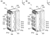
- the battery module 200 according to the second embodiment is different from the battery module 100 according to the first embodiment described above in that the reinforcing member 222 and the case 221 are fitted to each other by the concave and convex fitting portions.
- FIG. 4A is a perspective view showing the main part of the battery module 200.
- FIG. 4B is a perspective view showing a main part of the battery module 300.
- the reinforcing member 222 of the housing 220 includes a fitting portion 222g at the end facing the second extending portion 221d.
- the fitting portion 222g is formed by combining a rectangular concave shape and a convex shape along the Y direction.
- the case 221 includes a second extending portion 221d at an end portion of the reinforcing member 222 facing the fitting portion 222g.
- the second extending portion 221d is formed by combining a rectangular convex shape and a concave shape that are fitted to the fitting portion 222g.
- the battery module 300 is shown in FIG.
- the reinforcing member 322 of the housing 320 includes a fitting portion 322g at the end facing the second extending portion 321d.
- the fitting portion 322g is formed by combining a wavy concave shape and a convex shape along the Y direction.
- the case 321 includes a second extending portion 321d at the end facing the fitting portion 322g of the reinforcing member 322.
- the second extending portion 321d is formed by combining a wavy convex shape and a concave shape that are fitted to the fitting portion 322g.
- the reinforcing member 222 includes one fitting portion 222g formed by combining a concave shape and a convex shape at the end facing the second extending portion 221d.
- the 2nd extension part 221d is provided with the other fitting part 221g formed combining the convex shape and concave shape which fit with the one fitting part 222g.
- the fitting portion 222 g of the reinforcing member 222 and the fitting portion 221 g of the case 221 are fitted in an uneven shape, so that the case 221 intersects the stacking direction Z.
- the movement of the case 221 can be prevented by restricting the movement in the Y direction.
- the unit cell 110 has been described as the configuration of a lithium ion secondary battery, but is not limited to such a configuration.
- the unit cell 110 can be configured as, for example, a polymer lithium battery, a nickel-hydrogen battery, or a nickel-cadmium battery.
- the unit cell 110 has been described as a configuration of a secondary battery that is repeatedly charged and discharged, but is not limited to such a configuration.
- the single battery 110 can be configured as a primary battery that is used only once.
- the reinforcing member 122 has been described as being configured to be disposed outward along the stacking direction Z of the case 121.
- the reinforcing member 122 can be configured to be disposed inward along the stacking direction Z of the case 121 so as to be sandwiched between the case 121 and the unit cell 110.
- the reinforcing member has a protrusion in a direction away from the unit cell 110 along the stacking direction, and the second extending portion of the case is fitted to fit the protrusion along the stacking direction. It can be set as the structure provided with a joint hole or a fitting hole.
Abstract
Priority Applications (5)
| Application Number | Priority Date | Filing Date | Title |
|---|---|---|---|
| EP14882646.4A EP3107135B1 (fr) | 2014-02-12 | 2014-02-12 | Module de batterie |
| CN201480075249.7A CN105981197B (zh) | 2014-02-12 | 2014-02-12 | 电池组件 |
| JP2015562588A JP6168167B2 (ja) | 2014-02-12 | 2014-02-12 | 電池モジュール |
| PCT/JP2014/053202 WO2015121926A1 (fr) | 2014-02-12 | 2014-02-12 | Module de batterie |
| US15/113,102 US9812731B2 (en) | 2014-02-12 | 2014-02-12 | Battery module |
Applications Claiming Priority (1)
| Application Number | Priority Date | Filing Date | Title |
|---|---|---|---|
| PCT/JP2014/053202 WO2015121926A1 (fr) | 2014-02-12 | 2014-02-12 | Module de batterie |
Publications (1)
| Publication Number | Publication Date |
|---|---|
| WO2015121926A1 true WO2015121926A1 (fr) | 2015-08-20 |
Family
ID=53799696
Family Applications (1)
| Application Number | Title | Priority Date | Filing Date |
|---|---|---|---|
| PCT/JP2014/053202 WO2015121926A1 (fr) | 2014-02-12 | 2014-02-12 | Module de batterie |
Country Status (5)
| Country | Link |
|---|---|
| US (1) | US9812731B2 (fr) |
| EP (1) | EP3107135B1 (fr) |
| JP (1) | JP6168167B2 (fr) |
| CN (1) | CN105981197B (fr) |
| WO (1) | WO2015121926A1 (fr) |
Cited By (1)
| Publication number | Priority date | Publication date | Assignee | Title |
|---|---|---|---|---|
| JP7371659B2 (ja) | 2021-03-31 | 2023-10-31 | トヨタ自動車株式会社 | 蓄電装置 |
Families Citing this family (6)
| Publication number | Priority date | Publication date | Assignee | Title |
|---|---|---|---|---|
| DE102016224318A1 (de) * | 2016-12-07 | 2018-06-07 | Audi Ag | Speicheranordnung |
| US11342633B2 (en) | 2017-02-06 | 2022-05-24 | Samsung Sdi Co., Ltd. | Current collecting system for battery module, battery module, and vehicle |
| PL3358649T3 (pl) * | 2017-02-06 | 2022-01-31 | Samsung Sdi Co., Ltd | Układ kolektora prądu modułu akumulatora |
| KR102312416B1 (ko) * | 2018-04-04 | 2021-10-12 | 주식회사 엘지에너지솔루션 | 배터리 모듈 |
| JP7378097B2 (ja) * | 2019-03-12 | 2023-11-13 | パナソニックIpマネジメント株式会社 | 積層電池 |
| JP7424338B2 (ja) * | 2021-03-31 | 2024-01-30 | トヨタ自動車株式会社 | 蓄電装置 |
Citations (10)
| Publication number | Priority date | Publication date | Assignee | Title |
|---|---|---|---|---|
| JPH11176400A (ja) * | 1997-10-06 | 1999-07-02 | Japan Storage Battery Co Ltd | 電池ケース |
| JP2003203615A (ja) * | 2001-12-28 | 2003-07-18 | Nec Corp | モジュール |
| JP2007095656A (ja) * | 2005-08-30 | 2007-04-12 | Sanyo Electric Co Ltd | 非水系二次電池 |
| JP2008059941A (ja) * | 2006-08-31 | 2008-03-13 | Nissan Motor Co Ltd | 電池モジュール |
| JP2009187889A (ja) * | 2008-02-08 | 2009-08-20 | Nissan Motor Co Ltd | 電池ケース及び組電池 |
| JP2011023268A (ja) * | 2009-07-17 | 2011-02-03 | Nissan Motor Co Ltd | 電池モジュール |
| JP2012119232A (ja) * | 2010-12-02 | 2012-06-21 | Nissan Motor Co Ltd | 組電池 |
| WO2013046549A1 (fr) * | 2011-09-28 | 2013-04-04 | パナソニック株式会社 | Bloc-batterie, son procédé de fabrication et boîtier de batterie |
| JP2013101809A (ja) * | 2011-11-08 | 2013-05-23 | Nissan Motor Co Ltd | 定置用電力システム |
| WO2013146097A1 (fr) * | 2012-03-29 | 2013-10-03 | 日産自動車株式会社 | Dispositif de fixation de barre omnibus et procédé de fixation de barre omnibus |
Family Cites Families (5)
| Publication number | Priority date | Publication date | Assignee | Title |
|---|---|---|---|---|
| JP5114944B2 (ja) * | 2006-12-26 | 2013-01-09 | 日産自動車株式会社 | 組電池 |
| JP2013008550A (ja) * | 2011-06-24 | 2013-01-10 | Sharp Corp | 二次電池およびその製造方法 |
| JP2013051100A (ja) * | 2011-08-31 | 2013-03-14 | Nissan Motor Co Ltd | バッテリ温調用モジュール |
| FR2993708B1 (fr) * | 2012-07-17 | 2014-11-07 | Renault Sas | Module de batterie d'accumulateurs a cellules comprimees |
| JP6252216B2 (ja) * | 2014-02-07 | 2017-12-27 | 株式会社Soken | 組電池 |
-
2014
- 2014-02-12 JP JP2015562588A patent/JP6168167B2/ja active Active
- 2014-02-12 US US15/113,102 patent/US9812731B2/en active Active
- 2014-02-12 EP EP14882646.4A patent/EP3107135B1/fr active Active
- 2014-02-12 WO PCT/JP2014/053202 patent/WO2015121926A1/fr active Application Filing
- 2014-02-12 CN CN201480075249.7A patent/CN105981197B/zh active Active
Patent Citations (10)
| Publication number | Priority date | Publication date | Assignee | Title |
|---|---|---|---|---|
| JPH11176400A (ja) * | 1997-10-06 | 1999-07-02 | Japan Storage Battery Co Ltd | 電池ケース |
| JP2003203615A (ja) * | 2001-12-28 | 2003-07-18 | Nec Corp | モジュール |
| JP2007095656A (ja) * | 2005-08-30 | 2007-04-12 | Sanyo Electric Co Ltd | 非水系二次電池 |
| JP2008059941A (ja) * | 2006-08-31 | 2008-03-13 | Nissan Motor Co Ltd | 電池モジュール |
| JP2009187889A (ja) * | 2008-02-08 | 2009-08-20 | Nissan Motor Co Ltd | 電池ケース及び組電池 |
| JP2011023268A (ja) * | 2009-07-17 | 2011-02-03 | Nissan Motor Co Ltd | 電池モジュール |
| JP2012119232A (ja) * | 2010-12-02 | 2012-06-21 | Nissan Motor Co Ltd | 組電池 |
| WO2013046549A1 (fr) * | 2011-09-28 | 2013-04-04 | パナソニック株式会社 | Bloc-batterie, son procédé de fabrication et boîtier de batterie |
| JP2013101809A (ja) * | 2011-11-08 | 2013-05-23 | Nissan Motor Co Ltd | 定置用電力システム |
| WO2013146097A1 (fr) * | 2012-03-29 | 2013-10-03 | 日産自動車株式会社 | Dispositif de fixation de barre omnibus et procédé de fixation de barre omnibus |
Non-Patent Citations (1)
| Title |
|---|
| See also references of EP3107135A4 * |
Cited By (1)
| Publication number | Priority date | Publication date | Assignee | Title |
|---|---|---|---|---|
| JP7371659B2 (ja) | 2021-03-31 | 2023-10-31 | トヨタ自動車株式会社 | 蓄電装置 |
Also Published As
| Publication number | Publication date |
|---|---|
| CN105981197B (zh) | 2019-08-30 |
| JP6168167B2 (ja) | 2017-07-26 |
| EP3107135A1 (fr) | 2016-12-21 |
| EP3107135A4 (fr) | 2017-03-01 |
| JPWO2015121926A1 (ja) | 2017-03-30 |
| US20170012315A1 (en) | 2017-01-12 |
| EP3107135B1 (fr) | 2019-04-03 |
| CN105981197A (zh) | 2016-09-28 |
| US9812731B2 (en) | 2017-11-07 |
Similar Documents
| Publication | Publication Date | Title |
|---|---|---|
| JP6168167B2 (ja) | 電池モジュール | |
| KR102270266B1 (ko) | 버스바 어셈블리를 구비한 배터리 모듈 | |
| EP3316349B1 (fr) | Procédé de fabrication de dispositif électrochimique | |
| KR101424377B1 (ko) | 박형 전지 | |
| JP2012124146A (ja) | 二次電池、バッテリユニットおよびバッテリモジュール | |
| JP4096664B2 (ja) | ラミネート電池 | |
| US10622615B2 (en) | Electrochemical device | |
| US11715855B2 (en) | Battery module | |
| KR101590259B1 (ko) | 전극 조립체, 이를 포함하는 전지 및 디바이스 | |
| JP2012113843A (ja) | 電池およびその製造方法、バッテリユニット、ならびにバッテリモジュール | |
| JP2009004361A (ja) | 積層型電池 | |
| US8703342B2 (en) | Electrode assembly, rechargeable battery including the same, and method of manufacturing an electrode thereof | |
| JP6899746B2 (ja) | 全固体電池およびその製造方法 | |
| US9099691B2 (en) | Rechargeable battery | |
| CN110892555B (zh) | 电极组件及其制造方法和包括该电极组件的二次电池 | |
| JP6943832B2 (ja) | 固定具および蓄電池モジュール | |
| JP2018107008A (ja) | 全固体電池の製造方法 | |
| KR101834605B1 (ko) | 폴리머 배터리 및 폴리머 배터리 제조 방법 | |
| JP2007048668A (ja) | 電池及び組電池 | |
| KR20150122340A (ko) | 다수의 전극 탭들을 포함하는 젤리-롤형 전극조립체 | |
| KR20190112582A (ko) | 균일 면압 전지셀 카트리지 | |
| US20230147419A1 (en) | All-solid-state battery | |
| CN116169432A (zh) | 电池单体 | |
| JP2016035876A (ja) | 電池モジュール | |
| JP2008159592A (ja) | ラミネート電池、組電池モジュール、組電池およびこの電池を搭載した車両 |
Legal Events
| Date | Code | Title | Description |
|---|---|---|---|
| 121 | Ep: the epo has been informed by wipo that ep was designated in this application |
Ref document number: 14882646 Country of ref document: EP Kind code of ref document: A1 |
|
| WWE | Wipo information: entry into national phase |
Ref document number: 15113102 Country of ref document: US |
|
| ENP | Entry into the national phase |
Ref document number: 2015562588 Country of ref document: JP Kind code of ref document: A |
|
| NENP | Non-entry into the national phase |
Ref country code: DE |
|
| REEP | Request for entry into the european phase |
Ref document number: 2014882646 Country of ref document: EP |
|
| WWE | Wipo information: entry into national phase |
Ref document number: 2014882646 Country of ref document: EP |