WO2015119012A1 - 手術システムおよび手術システムの作動方法 - Google Patents
手術システムおよび手術システムの作動方法 Download PDFInfo
- Publication number
- WO2015119012A1 WO2015119012A1 PCT/JP2015/052328 JP2015052328W WO2015119012A1 WO 2015119012 A1 WO2015119012 A1 WO 2015119012A1 JP 2015052328 W JP2015052328 W JP 2015052328W WO 2015119012 A1 WO2015119012 A1 WO 2015119012A1
- Authority
- WO
- WIPO (PCT)
- Prior art keywords
- unit
- distance
- treatment
- mode
- body cavity
- Prior art date
- Legal status (The legal status is an assumption and is not a legal conclusion. Google has not performed a legal analysis and makes no representation as to the accuracy of the status listed.)
- Ceased
Links
Images






Classifications
-
- A—HUMAN NECESSITIES
- A61—MEDICAL OR VETERINARY SCIENCE; HYGIENE
- A61B—DIAGNOSIS; SURGERY; IDENTIFICATION
- A61B1/00—Instruments for performing medical examinations of the interior of cavities or tubes of the body by visual or photographical inspection, e.g. endoscopes; Illuminating arrangements therefor
- A61B1/00064—Constructional details of the endoscope body
- A61B1/00071—Insertion part of the endoscope body
- A61B1/0008—Insertion part of the endoscope body characterised by distal tip features
- A61B1/00097—Sensors
-
- A—HUMAN NECESSITIES
- A61—MEDICAL OR VETERINARY SCIENCE; HYGIENE
- A61B—DIAGNOSIS; SURGERY; IDENTIFICATION
- A61B1/00—Instruments for performing medical examinations of the interior of cavities or tubes of the body by visual or photographical inspection, e.g. endoscopes; Illuminating arrangements therefor
- A61B1/00002—Operational features of endoscopes
- A61B1/00043—Operational features of endoscopes provided with output arrangements
- A61B1/00045—Display arrangement
-
- A—HUMAN NECESSITIES
- A61—MEDICAL OR VETERINARY SCIENCE; HYGIENE
- A61B—DIAGNOSIS; SURGERY; IDENTIFICATION
- A61B1/00—Instruments for performing medical examinations of the interior of cavities or tubes of the body by visual or photographical inspection, e.g. endoscopes; Illuminating arrangements therefor
- A61B1/005—Flexible endoscopes
-
- A—HUMAN NECESSITIES
- A61—MEDICAL OR VETERINARY SCIENCE; HYGIENE
- A61B—DIAGNOSIS; SURGERY; IDENTIFICATION
- A61B1/00—Instruments for performing medical examinations of the interior of cavities or tubes of the body by visual or photographical inspection, e.g. endoscopes; Illuminating arrangements therefor
- A61B1/04—Instruments for performing medical examinations of the interior of cavities or tubes of the body by visual or photographical inspection, e.g. endoscopes; Illuminating arrangements therefor combined with photographic or television appliances
- A61B1/05—Instruments for performing medical examinations of the interior of cavities or tubes of the body by visual or photographical inspection, e.g. endoscopes; Illuminating arrangements therefor combined with photographic or television appliances characterised by the image sensor, e.g. camera, being in the distal end portion
-
- A—HUMAN NECESSITIES
- A61—MEDICAL OR VETERINARY SCIENCE; HYGIENE
- A61B—DIAGNOSIS; SURGERY; IDENTIFICATION
- A61B1/00—Instruments for performing medical examinations of the interior of cavities or tubes of the body by visual or photographical inspection, e.g. endoscopes; Illuminating arrangements therefor
- A61B1/313—Instruments for performing medical examinations of the interior of cavities or tubes of the body by visual or photographical inspection, e.g. endoscopes; Illuminating arrangements therefor for introducing through surgical openings, e.g. laparoscopes
- A61B1/3132—Instruments for performing medical examinations of the interior of cavities or tubes of the body by visual or photographical inspection, e.g. endoscopes; Illuminating arrangements therefor for introducing through surgical openings, e.g. laparoscopes for laparoscopy
-
- A—HUMAN NECESSITIES
- A61—MEDICAL OR VETERINARY SCIENCE; HYGIENE
- A61B—DIAGNOSIS; SURGERY; IDENTIFICATION
- A61B18/00—Surgical instruments, devices or methods for transferring non-mechanical forms of energy to or from the body
- A61B18/04—Surgical instruments, devices or methods for transferring non-mechanical forms of energy to or from the body by heating
- A61B18/12—Surgical instruments, devices or methods for transferring non-mechanical forms of energy to or from the body by heating by passing a current through the tissue to be heated, e.g. high-frequency current
- A61B18/14—Probes or electrodes therefor
- A61B18/1402—Probes for open surgery
-
- A—HUMAN NECESSITIES
- A61—MEDICAL OR VETERINARY SCIENCE; HYGIENE
- A61B—DIAGNOSIS; SURGERY; IDENTIFICATION
- A61B18/00—Surgical instruments, devices or methods for transferring non-mechanical forms of energy to or from the body
- A61B18/04—Surgical instruments, devices or methods for transferring non-mechanical forms of energy to or from the body by heating
- A61B18/12—Surgical instruments, devices or methods for transferring non-mechanical forms of energy to or from the body by heating by passing a current through the tissue to be heated, e.g. high-frequency current
- A61B18/14—Probes or electrodes therefor
- A61B18/1442—Probes having pivoting end effectors, e.g. forceps
- A61B18/1445—Probes having pivoting end effectors, e.g. forceps at the distal end of a shaft, e.g. forceps or scissors at the end of a rigid rod
-
- A—HUMAN NECESSITIES
- A61—MEDICAL OR VETERINARY SCIENCE; HYGIENE
- A61B—DIAGNOSIS; SURGERY; IDENTIFICATION
- A61B34/00—Computer-aided surgery; Manipulators or robots specially adapted for use in surgery
- A61B34/20—Surgical navigation systems; Devices for tracking or guiding surgical instruments, e.g. for frameless stereotaxis
-
- A—HUMAN NECESSITIES
- A61—MEDICAL OR VETERINARY SCIENCE; HYGIENE
- A61B—DIAGNOSIS; SURGERY; IDENTIFICATION
- A61B5/00—Measuring for diagnostic purposes; Identification of persons
- A61B5/06—Devices, other than using radiation, for detecting or locating foreign bodies ; Determining position of diagnostic devices within or on the body of the patient
- A61B5/061—Determining position of a probe within the body employing means separate from the probe, e.g. sensing internal probe position employing impedance electrodes on the surface of the body
- A61B5/062—Determining position of a probe within the body employing means separate from the probe, e.g. sensing internal probe position employing impedance electrodes on the surface of the body using magnetic field
-
- A—HUMAN NECESSITIES
- A61—MEDICAL OR VETERINARY SCIENCE; HYGIENE
- A61B—DIAGNOSIS; SURGERY; IDENTIFICATION
- A61B5/00—Measuring for diagnostic purposes; Identification of persons
- A61B5/06—Devices, other than using radiation, for detecting or locating foreign bodies ; Determining position of diagnostic devices within or on the body of the patient
- A61B5/061—Determining position of a probe within the body employing means separate from the probe, e.g. sensing internal probe position employing impedance electrodes on the surface of the body
- A61B5/064—Determining position of a probe within the body employing means separate from the probe, e.g. sensing internal probe position employing impedance electrodes on the surface of the body using markers
-
- A—HUMAN NECESSITIES
- A61—MEDICAL OR VETERINARY SCIENCE; HYGIENE
- A61B—DIAGNOSIS; SURGERY; IDENTIFICATION
- A61B90/00—Instruments, implements or accessories specially adapted for surgery or diagnosis and not covered by any of the groups A61B1/00 - A61B50/00, e.g. for luxation treatment or for protecting wound edges
- A61B90/06—Measuring instruments not otherwise provided for
-
- A—HUMAN NECESSITIES
- A61—MEDICAL OR VETERINARY SCIENCE; HYGIENE
- A61B—DIAGNOSIS; SURGERY; IDENTIFICATION
- A61B90/00—Instruments, implements or accessories specially adapted for surgery or diagnosis and not covered by any of the groups A61B1/00 - A61B50/00, e.g. for luxation treatment or for protecting wound edges
- A61B90/39—Markers, e.g. radio-opaque or breast lesions markers
-
- A—HUMAN NECESSITIES
- A61—MEDICAL OR VETERINARY SCIENCE; HYGIENE
- A61B—DIAGNOSIS; SURGERY; IDENTIFICATION
- A61B18/00—Surgical instruments, devices or methods for transferring non-mechanical forms of energy to or from the body
- A61B18/04—Surgical instruments, devices or methods for transferring non-mechanical forms of energy to or from the body by heating
- A61B18/12—Surgical instruments, devices or methods for transferring non-mechanical forms of energy to or from the body by heating by passing a current through the tissue to be heated, e.g. high-frequency current
- A61B18/14—Probes or electrodes therefor
- A61B18/1492—Probes or electrodes therefor having a flexible, catheter-like structure, e.g. for heart ablation
-
- A—HUMAN NECESSITIES
- A61—MEDICAL OR VETERINARY SCIENCE; HYGIENE
- A61B—DIAGNOSIS; SURGERY; IDENTIFICATION
- A61B18/00—Surgical instruments, devices or methods for transferring non-mechanical forms of energy to or from the body
- A61B2018/00571—Surgical instruments, devices or methods for transferring non-mechanical forms of energy to or from the body for achieving a particular surgical effect
- A61B2018/00595—Cauterization
-
- A—HUMAN NECESSITIES
- A61—MEDICAL OR VETERINARY SCIENCE; HYGIENE
- A61B—DIAGNOSIS; SURGERY; IDENTIFICATION
- A61B18/00—Surgical instruments, devices or methods for transferring non-mechanical forms of energy to or from the body
- A61B18/04—Surgical instruments, devices or methods for transferring non-mechanical forms of energy to or from the body by heating
- A61B18/12—Surgical instruments, devices or methods for transferring non-mechanical forms of energy to or from the body by heating by passing a current through the tissue to be heated, e.g. high-frequency current
- A61B18/14—Probes or electrodes therefor
- A61B2018/1405—Electrodes having a specific shape
- A61B2018/1412—Blade
-
- A—HUMAN NECESSITIES
- A61—MEDICAL OR VETERINARY SCIENCE; HYGIENE
- A61B—DIAGNOSIS; SURGERY; IDENTIFICATION
- A61B90/00—Instruments, implements or accessories specially adapted for surgery or diagnosis and not covered by any of the groups A61B1/00 - A61B50/00, e.g. for luxation treatment or for protecting wound edges
- A61B90/06—Measuring instruments not otherwise provided for
- A61B2090/061—Measuring instruments not otherwise provided for for measuring dimensions, e.g. length
-
- A—HUMAN NECESSITIES
- A61—MEDICAL OR VETERINARY SCIENCE; HYGIENE
- A61B—DIAGNOSIS; SURGERY; IDENTIFICATION
- A61B90/00—Instruments, implements or accessories specially adapted for surgery or diagnosis and not covered by any of the groups A61B1/00 - A61B50/00, e.g. for luxation treatment or for protecting wound edges
- A61B90/39—Markers, e.g. radio-opaque or breast lesions markers
- A61B2090/3904—Markers, e.g. radio-opaque or breast lesions markers specially adapted for marking specified tissue
- A61B2090/3912—Body cavities
-
- A—HUMAN NECESSITIES
- A61—MEDICAL OR VETERINARY SCIENCE; HYGIENE
- A61B—DIAGNOSIS; SURGERY; IDENTIFICATION
- A61B5/00—Measuring for diagnostic purposes; Identification of persons
- A61B5/103—Measuring devices for testing the shape, pattern, colour, size or movement of the body or parts thereof, for diagnostic purposes
- A61B5/107—Measuring physical dimensions, e.g. size of the entire body or parts thereof
- A61B5/1076—Measuring physical dimensions, e.g. size of the entire body or parts thereof for measuring dimensions inside body cavities, e.g. using catheters
Definitions
- the present invention relates to a surgical system and a method for operating the surgical system.
- LCS laparoscopic endoscopic surgery
- a laparoscope and an endoscope while observing the surgical area from both inside and outside the body cavity.
- Patent Document 1 For example, when resecting a lesion existing on the inner wall of the stomach, the resection line is determined by observing the lesion from the inside of the stomach with an endoscope, and the stomach wall is measured from the outside of the stomach along the determined resection line.
- the incision range can be minimized by making an incision with a treatment tool such as the above.
- Patent Document 1 a magnet or LED is provided at the distal end of the endoscope, and the position of the endoscope in the body cavity can be detected by detecting the magnetic field from the magnet or the light from the LED outside the body cavity.
- the diameter of the polyp formed on the inner wall of the body cavity is about 20 mm to 50 mm, and in order to minimize the excision range, the treatment tool is positioned with a positional accuracy in millimeters with respect to the determined excision line. Is required. Accordingly, when the doctor manually positions the treatment tool based on the detected position of the endoscope as in Patent Document 1, a very high skill is required of the doctor. In particular, in Patent Document 1, a doctor must specify the position of an endoscope in a body cavity based on the sound output according to the strength of the magnetic field and the brightness of light from the LED. As described above, the method of determining the position where the treatment tool is to be arranged based on the sense of the doctor places a heavy burden on the doctor and there is a problem that it is difficult to accurately position the treatment tool.
- the present invention has been made in view of the above-described circumstances, and in LECS that treats a body cavity while observing it from both inside and outside, the treatment tool is attached to the treatment position of the body cavity determined by observing from the inside. It is an object of the present invention to provide a surgical system and a method for operating the surgical system that can be accurately positioned from the outside and can accurately treat the determined treatment position.
- a first medical instrument that is disposed inside a body cavity, has an observation unit that observes the body cavity, and a marker that can be positioned with respect to the body cavity, and an outer side of the body cavity.
- Distance measurement that measures the distance between the second medical instrument that is disposed and has a treatment part that performs treatment on the body cavity, and a drive part that drives the treatment part, and the marker part and the treatment part
- a control unit that controls the drive unit based on the distance measured by the distance measurement unit.
- the control unit is The treatment unit is moved by controlling the drive unit. Therefore, by positioning the marker part at the treatment position such as a lesion part specified based on the image in the body cavity observed by the observation part, the treatment part is arranged at an appropriate position via the cavity wall with respect to the treatment position. can do.
- the treatment section can be positioned with high accuracy. Accordingly, the treatment tool can be accurately positioned from the outside with respect to the treatment position of the body cavity that is determined by observation from the inside, and the determined treatment position can be accurately treated.
- the drive unit may be controlled so that the treatment unit is positioned at a position where the distance is equal to or less than a predetermined first threshold value.
- a predetermined first threshold value for example, a value approximately equivalent to the thickness dimension of the cavity wall
- the treatment section is placed through the cavity wall. It can be positioned at a position substantially opposite to. Thereby, the position of the lesioned part in the body cavity can be accurately recognized from outside the body cavity.
- the distance measurement unit repeatedly measures the distance
- the control unit measures the distance every time the distance measured by the distance measurement unit exceeds the predetermined first threshold.
- the drive unit may be repeatedly driven so that the treatment unit is repositioned at a position where the value is equal to or less than the predetermined first threshold value.
- the control unit detects that as an increase in the distance measured by the distance measuring unit, and controls the driving unit to move the marker part and cavity wall after the movement. Then, the treatment part is positioned again at a position substantially opposite to each other. In this way, by causing the treatment portion to follow the movement of the marker portion, the tissue can be treated along the locus of the marker portion.
- control unit may control the driving unit such that the treatment unit is disposed at a position where the distance is greater than a predetermined second threshold.
- the control unit includes an automatic alignment mode for controlling the drive unit so as to position the treatment unit at a position where the distance is equal to or less than a predetermined first threshold value.
- the treatment unit is repositioned at a position where the distance is equal to or less than the predetermined first threshold value.
- the treatment section is arranged in a second mode including a follow-up mode in which the driving section is repeatedly driven and a position where the distance is larger than a predetermined second threshold value that is larger than the predetermined first threshold value.
- a third mode including a sign section avoidance mode for controlling the driving section, and the first mode, the second mode, and the third mode are alternatively selected by an operator. It has a mode selection section It may be. By doing in this way, an operator can select the mode most suitable for the content of treatment, the situation at that time, etc. using a mode selection part.
- a distance measuring step for measuring a distance between a marker portion positioned inside a body cavity and a treatment portion of a medical instrument disposed outside the body cavity, and the distance measuring step And a treatment portion moving step of moving the treatment portion based on the distance measured in step (b).
- the treatment tool in LECS which treats while observing the body cavity from both inside and outside, is accurately positioned from the outside with respect to the treatment position of the body cavity determined by observing from the inside, and the determined treatment position There is an effect that can be accurately treated.
- the surgery system 1 which concerns on the 1st Embodiment of this invention is demonstrated with reference to FIGS. 1-6B.
- the surgical system 1 treats a body cavity A from the outside while observing the body cavity A from both the inside and the outside using an endoscope 2 and a laparoscope 3. It is used for laparoscopic combined surgery (LECS).
- the surgical system 1 includes an endoscope 2, a laparoscope 3, a treatment instrument 4, an operation input device 5 operated by a doctor (operator), and the operation And a controller 6 that controls the treatment instrument 4 based on an input to the input device 5.
- the endoscope 2 includes an elongated flexible insertion portion 21 that can be inserted into the body cavity A, and an imaging element (observation unit) 22 built in the distal end of the insertion portion 21, and the body cavity acquired by the imaging element 22.
- the video in A is transmitted to the monitor 7.
- the endoscope 2 has a marker (marking unit) 23 that generates a signal (for example, a magnetic field, light, heat, voltage) that propagates through the cavity wall B from the inside to the outside of the body cavity A.
- the marker 23 is provided, for example, at the tip of a wire 25 that is movably inserted in the longitudinal direction in a channel 24 that is formed through the insertion portion 21 along the longitudinal direction.
- the doctor can move the marker 23 in the body cavity A by operating the proximal end portion of the wire 25, and can fix the marker 23 to the inner wall of the body cavity A by fixing the wire 25 to the insertion portion 21. Can be positioned.
- any treatment instrument that can be inserted into the channel 24 may be used.
- the laparoscope 3 can be inserted into the body percutaneously, and transmits the acquired image inside the body to the monitor 7.
- the treatment instrument 4 includes an elongated rigid body portion 41 that can be inserted into the body percutaneously, a treatment portion 42 that is provided on the distal end side of the body portion 41 and that treats tissue, and the body portion 41 and the treatment portion. And a drive unit 44 that drives the joint unit 43.
- an electric knife hereinafter also referred to as an electric knife 42
- the treatment section 42 may be other types such as forceps and scissors. .
- the electric knife 42 is provided with a distance measuring unit 8 that measures a distance between the electric knife 42 and the marker 23 by detecting a signal generated by the marker 23.
- a distance measuring unit 8 that measures a distance between the electric knife 42 and the marker 23 by detecting a signal generated by the marker 23.
- a magnet permanent magnet or electromagnet
- a Hall element or coil for example, a near infrared laser light source and a light detector, a projector and a light receiver, a heating element and a heat are used. Examples include a detector, an AC voltage generating element, and an impedance detector.
- the distance measuring unit 8 detects the intensity of magnetism or light, temperature, or impedance, and based on the obtained detection value, the marker 23 and the electric knife arranged via the cavity wall B The distance to 42 is measured.
- the joint portion 43 supports the electric knife 42 so as to be swingable in a two-dimensional direction intersecting the longitudinal direction of the body portion 41.
- the drive unit 44 drives the joint unit 43 based on the control signal received from the controller 6, thereby moving the electric knife 42 in a two-dimensional direction intersecting the longitudinal direction of the body unit 41.
- the operation input device 5 generates an operation signal corresponding to the operation performed by the doctor, and transmits the generated operation signal to the controller 6.
- the controller 6 includes a control unit 61 that controls the endoscope 2 and the treatment instrument 4, and a storage unit 62.
- the control unit 61 permits the operation of the treatment instrument 4 via the operation input device 5 and controls the drive unit 44 according to the operation input to the operation input device 5 by the doctor, and the operation input device.
- 5 has an “automatic alignment mode” in which the operation of the treatment instrument 4 via 5 is prohibited and the drive unit 44 is controlled based on the distance measured by the distance measuring unit 8. These two modes can be alternatively selected by a doctor using a switch or the like provided in the controller 6. Next, the “manual alignment mode” and the “automatic alignment mode” will be described in detail.
- FIG. 3 is a flowchart for explaining the control contents of the control unit 61 in the “manual alignment mode”.
- the control unit 61 first causes the distance measurement unit 8 to measure the distance between the marker 23 and the electric knife 42 (step SA1). Then, when the measured distance is larger than the predetermined first threshold Th1 (NO in step SA2), the control unit 61 outputs the first sound from a speaker (not shown) with a volume inversely proportional to the distance. (Step SA3). On the other hand, when the measured distance is equal to or less than the predetermined first threshold value Th1 (YES in step SA2), the control unit 61 determines that the second sound is different from the first sound in pitch, tone, melody, and the like.
- step SA4 The controller 61 repeats steps SA1 to SA4 described above while the “manual alignment mode” is selected.
- the first threshold value Th ⁇ b> 1 is set to be smaller than the radius of the movable range of the electric knife 42 driven by the joint portion 43.
- the doctor moves the electric knife 42 arranged outside the body cavity A in the direction in which the first sound increases, thereby arranging the electric knife 42 inside the body cavity A.
- the marker 23 can be approached.
- the doctor moves the first knife from the first sound to the second sound, and the electric knife 42 has a spherical area centered on the marker 23 and having the first threshold Th1 as the radius. Can be recognized.
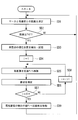
- FIG. 4 is a flowchart for explaining the control contents of the control unit 61 in the “automatic alignment mode”.
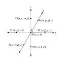
- the control unit 61 first stores the current position of the electric knife 42 relative to the torso 41 (step SB1), and sets the current position to the reference position P0.
- the electric knife 42 is moved (step SB3), and the distance measurement unit 8 is made to measure the distance at each position (distance measurement step SB4).
- the measured distance is stored in the storage unit 62 in association with the position Pi.
- step SB2 After the measurement of the distances at all the positions Pi is completed (steps SB2, SB5, SB6), the control unit 61 sets the position at which the shortest distance is measured among all the distances stored in the storage unit 62 as the closest position. And the electric knife 42 is placed again at the closest position (treatment section moving step SB7). Then, the closest position is set to a new reference position P0, and the above-described steps SB1 to SB6 are repeated (NO in step SB8).
- the second threshold Th2 is equal to or slightly larger than the thickness of the cavity wall B (for example, the thickness of the cavity wall B + several mm). That is, in the “automatic alignment mode”, as shown in FIG. 6B, the electric knife 42 is disposed substantially opposite to the marker 23 through the cavity wall B, and the distance to the marker 23 is minimized. Eventually it will be positioned.
- the switching from the “manual alignment mode” to the “automatic alignment mode” may be automatically performed by the control unit 61. That is, when the distance measured by the distance measuring unit 8 in the “manual alignment mode” is equal to or less than the predetermined first threshold Th1, the control unit 61 forcibly ends the “manual alignment mode”. Then, the “automatic alignment mode” may be started.
- the doctor In order to excise the lesioned part C existing on the inner wall of the body cavity A using the surgical system 1 according to the present embodiment, the doctor first inserts the laparoscope 3 and the treatment tool 4 into the body percutaneously, The scalpel 42 is placed outside the body cavity A, and the laparoscope 3 is placed at a position where the scalpel 42 can be observed. Further, the doctor inserts the endoscope 2 into the body cavity A, observes the lesioned part C with an endoscope image, determines an incision line surrounding the lesioned part C, and positions the marker 23 on the incision line.
- the doctor activates the “manual alignment mode”.
- the electric knife 42 When the electric knife 42 is disposed at a position away from the marker 23, a small first sound is output.
- the doctor operates the operation input device 5 to move the electric knife 42 in the direction in which the first sound increases, and searches for a region where the first sound changes to the second sound. Then, the electric knife 42 is positioned at a position where the second sound is output. As a result, the electric knife 42 is roughly positioned with respect to the marker 23.
- the doctor activates the “automatic alignment mode”. Thereafter, the electric knife 42 is positioned at a position substantially opposite to the marker 23 via the cavity wall B by driving the joint portion 43 by the control unit 61. The doctor cuts the cavity wall B with the electric knife 42 at the finally positioned position. Thereafter, the doctor moves the marker 23 along the incision line and positions the electric knife 42 in two stages of “manual alignment mode” and “automatic alignment mode” to incise the cavity wall B. repeat. Thereby, the cavity wall B is cut along the incision line determined first, and the lesioned part C can be excised.
- a desired incision position is marked with the marker 23, and the electric knife 42 with respect to the incision position is automatically controlled to finely align the electric knife 42 with the marker 23.
- the doctor can incise the cavity wall B along the ideal incision line determined based on the endoscopic image and can minimize the resection range of the cavity wall B. .
- a contact detection unit that detects contact between the electric knife 42 and the tissue.
- the tissue contact portion is composed of, for example, a conductive sensor that electrically detects contact between the electric knife 42 and the tissue.
- the control unit 61 stops measuring the distance at the position Pi and moves to the measurement at the next position Pi + 1, or The distance is measured at a position where the electric knife 42 does not contact the tissue. By doing in this way, it can prevent that the electric knife 42 contacts a structure
- the treatment instrument 4 and the treatment instrument inserted into the channel 24 of the endoscope 2 constitute a bipolar type electrosurgical electrode and are provided at the distal end of the treatment instrument on the endoscope 2 side. Only when the distance between the marked marker 23 and the treatment instrument 4 is equal to or less than the second threshold Th2, the supply of the high-frequency current to the electrode may be permitted. Even in this way, the doctor can cut only the position determined by the doctor.
- control unit 61 has the “lesion site avoidance mode (marker portion avoidance mode)” in addition to the “manual alignment mode” and the “automatic alignment mode”. Different from the embodiment. Therefore, in the present embodiment, the “lesional part avoidance mode” will be mainly described, and the description of the configuration common to the first embodiment will be omitted.
- the “manual alignment mode”, “automatic alignment mode”, and “lesioned part avoidance mode” can be alternatively selected by a doctor using a switch or the like provided in the controller 6. Yes.
- FIG. 7 is a flowchart for explaining the control contents of the control unit 61 in the “lesion site avoidance mode”.
- the “lesion avoidance mode” is used after the positioning of the electric knife 42 with respect to the marker 23 in the “automatic alignment mode” is completed.
- the control unit 61 firstly performs the treatment unit. 42 is stored (step SC1). Normally, the position stored at this time is a position substantially opposed to the marker 23 via the cavity wall B finally determined in the “automatic alignment mode” as shown in FIG. 8A. Therefore, the control unit 61 can obtain the position of the marker 23 from the current position of the electric knife 42 and the second threshold Th2.
- the controller 61 causes the doctor to input a radius (predetermined second threshold) L via the operation input device 5 (step SC2).
- the radius L is a radius of a prohibited area where the placement of the electric knife 42 is prohibited.
- the control unit 61 moves the electric knife 42 to the outside of the prohibited area having the radius L with the position of the marker 23 as the center (step SC3). Thereafter, the control unit 61 permits the operation of the electric knife 42 by the doctor through the operation input device 5 (step SC4).
- the control unit 61 measures the distance between the movement destination of the electric knife 42 input by the doctor to the operation input device 5 and the marker 23 by calculation, and compares the obtained distance with the radius L to determine the movement destination. It is determined whether or not the area is outside the prohibited area (distance measurement step SC5). When the movement destination of the electric knife 42 is outside the prohibited area (YES in step SC5), the control unit 61 moves the electric knife 42 according to the operator's input (treatment section movement step SC6). On the other hand, when the movement destination of the electric knife 42 is inside the prohibited area (NO in step SC5), the control unit 61 rejects the input and stops the electric knife 42 on the spot (step SC7). At this time, the control unit 61 may notify the doctor that the movement destination of the electric knife 42 is inside the prohibited area.
- the doctor positions the marker 23 at the center of the lesion C as shown in FIG. 8A.
- the doctor places the electric knife 42 at a position substantially opposite to the marker 23 via the cavity wall B by the “manual alignment mode” and the “automatic alignment mode”. Position.
- the doctor activates the “lesioned part avoidance mode” and remotely operates the electric knife 42 using the operation input device 5.
- the doctor can operate the electric knife 42 only outside the forbidden region having the radius L from the center of the lesion site C.
- this embodiment is used when the cavity wall B must be cut at a position avoiding the lesioned part C. Accordingly, there is an advantage that the doctor can cut out the periphery of the lesioned part C and remove the lesioned part C while the lesioned part C is preserved.
- the electric knife 42 when the movement destination of the electric knife 42 input by the doctor to the operation input device 5 is in the prohibited area, the electric knife 42 is moved according to the input instead of stopping the movement of the electric knife 42.
- the supply of the high-frequency current to the electric knife 42 may be prohibited.
- control unit 61 may automatically perform switching from the “manual alignment mode” to the “automatic alignment mode” and from the “automatic alignment mode” to the “lesioned part avoidance mode”. That is, the control unit 61 forcibly ends the “manual alignment mode” when the distance measured by the distance measurement unit 8 in the “automatic alignment mode” is equal to or less than the predetermined first threshold Th1.
- the “automatic alignment mode” may be started, and the “lesioned part avoidance mode” may be started after the “automatic alignment mode” ends.
- FIGS. 9 to 10B a third embodiment of the present embodiment will be described with reference to FIGS. 9 to 10B.
- the present embodiment is different from the first embodiment in that the control unit 61 has a “following mode” instead of the “automatic alignment mode”. Therefore, in the present embodiment, the “follow-up mode” will be mainly described, and the description of the configuration common to the first embodiment will be omitted.
- the “manual alignment mode” and the “follow-up mode” can be alternatively selected by a doctor using a switch or the like provided in the controller 6.
- FIG. 9 is a flowchart for explaining the control content of the control unit 61 in the “follow-up mode”.
- the “follow-up mode” is used after the positioning of the electric knife 42 with respect to the marker 23 in the “manual alignment mode” is completed. After the electric knife 42 is arranged in the region of the radius Th1 centered on the marker 23 by the “manual alignment mode”, when the “manual alignment mode” is switched to the “following mode”, the control unit 61 causes the marker 61 to The distance measurement unit 8 is repeatedly made to measure the distance between the electric knife 23 and the electric knife 42 (distance measurement step SD1).
- Step SD2 the control unit 61 uses the same procedure as in the “automatic alignment mode”, and the distance is equal to or less than the second threshold Th2.
- Step SD3 to SD9 the positioning of the electric knife 42 with respect to the marker 23 is executed. That is, steps SD3 to SD9 in the “following mode” are the same as steps SB2 to SB8 in the “automatic alignment mode”.
- the marker 23 moves once after the control unit 61 positions the electric knife 42 at a position substantially opposite to the marker 23 via the cavity wall B. Then, the control part 61 detects the movement from the increase in the distance between the marker 23 and the electric knife 42, and again, as shown in FIG. 10B, again a position substantially facing the marker 23 via the cavity wall B. Reposition the electric knife 42. Thereby, the electric knife 42 is made to follow the movement of the marker 23.
- the doctor positions the marker 23 on the incision line determined by the doctor, and roughly sets the electric knife 42 relative to the marker 23 in the “manual alignment mode”. Align.
- the doctor activates the “follow-up mode”. Thereby, the electric knife 42 is positioned at a position substantially opposite to the marker 23 via the cavity wall B.
- the electric knife 42 automatically follows the movement of the marker 23. Again, the electric knife 42 is positioned at a position substantially opposite to the marker 23 via the cavity wall B. Thereafter, the doctor repeats the movement of the marker 23 and the incision with the electric knife 42 at the movement destination until the incision at all desired positions is completed.
- the electric knife 42 automatically follows the movement of the marker 23, so that the electric knife 42 is always disposed at a position substantially opposed to the marker 23 via the cavity wall B. . Therefore, there is an advantage that the doctor can incise the cavity wall B along the incision line by moving the marker 23 along the incision line determined by the doctor.
- the endoscope 2 to be inserted into the body cavity A must be flexible, but the flexible endoscope 2 is bent by the pressing force from the cavity wall B. It is difficult to incise the cavity wall B with the treatment tool introduced into the body cavity A. Therefore, the incision can be easily performed by specifying the resection line with the endoscope 2 and using the rigid treatment tool 4 capable of transmitting a force to the cavity wall B.
- the supply of the high-frequency current to the electric knife 42 is permitted only when the distance measured by the distance measuring unit 8 is equal to or less than the second threshold Th2. Good.
- the treatment instrument 4 and the treatment instrument inserted into the channel 24 of the endoscope 2 constitute an electrode of a bipolar electric scalpel 42, and a marker provided at the distal end of the treatment instrument on the endoscope 2 side.
- the supply of the high-frequency current to the electric knife 42 may be permitted only when the distance between the tool 23 and the treatment instrument 4 is equal to or less than the second threshold Th2.
- control unit 61 is configured to be able to selectively select the combination of the three types of modes described in the first to third embodiments. Different from form.
- the control unit 61 has a “first mode”, a “second mode”, and a “third mode”.
- the “first mode” includes a “manual alignment mode” and an “automatic alignment mode”.
- the “second mode” includes a “manual alignment mode” and a “follow-up mode”.
- the “third mode” includes a “manual alignment mode”, an “automatic alignment mode”, and a “lesioned part avoidance mode”.
- the surgical operation system 1 ′ includes a mode selection unit 9 that can alternatively select the first mode, the second mode, and the third mode by a doctor's operation.
- the mode selection unit 9 may be provided in the operation input device 5 or the controller 6.
- first mode is “automatic alignment mode”
- second mode is “follow-up mode”
- third mode is “lesion avoidance mode (marker avoidance mode)”. As long as each of them is included. Further, any two modes among the “first mode”, “second mode”, and “third mode” may be alternatively selectable.
- two or more distance measuring units 8 may be provided at different positions of the electric knife 42.
- the relative position of the electric knife 42 and the marker 23 is obtained by calculation from the distance measured by each distance measuring unit 8.
- the doctor can recognize the position of the marker 23 more accurately by presenting the obtained relative position to the doctor.
- the control unit 61 can cause the electric knife 42 to follow the marker 23 by moving the electric knife 42 by the obtained movement vector. Thereby, the responsiveness of the electric knife 42 with respect to the movement of the marker 23 can be improved.
Landscapes
- Health & Medical Sciences (AREA)
- Life Sciences & Earth Sciences (AREA)
- Surgery (AREA)
- Engineering & Computer Science (AREA)
- Veterinary Medicine (AREA)
- Public Health (AREA)
- General Health & Medical Sciences (AREA)
- Animal Behavior & Ethology (AREA)
- Molecular Biology (AREA)
- Biomedical Technology (AREA)
- Heart & Thoracic Surgery (AREA)
- Medical Informatics (AREA)
- Nuclear Medicine, Radiotherapy & Molecular Imaging (AREA)
- Pathology (AREA)
- Physics & Mathematics (AREA)
- Biophysics (AREA)
- Radiology & Medical Imaging (AREA)
- Optics & Photonics (AREA)
- Human Computer Interaction (AREA)
- Oral & Maxillofacial Surgery (AREA)
- Plasma & Fusion (AREA)
- Otolaryngology (AREA)
- Robotics (AREA)
- Surgical Instruments (AREA)
- Endoscopes (AREA)
Priority Applications (3)
| Application Number | Priority Date | Filing Date | Title |
|---|---|---|---|
| CN201580006874.0A CN105939688B (zh) | 2014-02-07 | 2015-01-28 | 手术系统和手术系统的工作方法 |
| EP15746625.1A EP3103411A4 (en) | 2014-02-07 | 2015-01-28 | Surgical system and method for operating surgical system |
| US15/223,622 US20160331473A1 (en) | 2014-02-07 | 2016-07-29 | Surgical system and surgical-system operating method |
Applications Claiming Priority (2)
| Application Number | Priority Date | Filing Date | Title |
|---|---|---|---|
| JP2014-022609 | 2014-02-07 | ||
| JP2014022609A JP6305088B2 (ja) | 2014-02-07 | 2014-02-07 | 手術システムおよび手術システムの作動方法 |
Related Child Applications (1)
| Application Number | Title | Priority Date | Filing Date |
|---|---|---|---|
| US15/223,622 Continuation US20160331473A1 (en) | 2014-02-07 | 2016-07-29 | Surgical system and surgical-system operating method |
Publications (1)
| Publication Number | Publication Date |
|---|---|
| WO2015119012A1 true WO2015119012A1 (ja) | 2015-08-13 |
Family
ID=53777819
Family Applications (1)
| Application Number | Title | Priority Date | Filing Date |
|---|---|---|---|
| PCT/JP2015/052328 Ceased WO2015119012A1 (ja) | 2014-02-07 | 2015-01-28 | 手術システムおよび手術システムの作動方法 |
Country Status (5)
| Country | Link |
|---|---|
| US (1) | US20160331473A1 (https=) |
| EP (1) | EP3103411A4 (https=) |
| JP (1) | JP6305088B2 (https=) |
| CN (1) | CN105939688B (https=) |
| WO (1) | WO2015119012A1 (https=) |
Cited By (3)
| Publication number | Priority date | Publication date | Assignee | Title |
|---|---|---|---|---|
| WO2018131188A1 (ja) * | 2017-01-13 | 2018-07-19 | 株式会社A-Traction | 手術支援装置、その制御方法、プログラム並びに手術支援システム |
| CN112004495A (zh) * | 2018-08-30 | 2020-11-27 | 瑞德医疗机器股份有限公司 | 推算装置、推算方法、以及程序 |
| JP2023504626A (ja) * | 2019-12-03 | 2023-02-06 | ボストン サイエンティフィック サイムド,インコーポレイテッド | 光源と、センサによる光の検出に基づいてセンサを移動させる手段とを有する医療撮像装置を備える医療システム |
Families Citing this family (63)
| Publication number | Priority date | Publication date | Assignee | Title |
|---|---|---|---|---|
| US11871901B2 (en) | 2012-05-20 | 2024-01-16 | Cilag Gmbh International | Method for situational awareness for surgical network or surgical network connected device capable of adjusting function based on a sensed situation or usage |
| EP3466361A1 (en) * | 2016-06-03 | 2019-04-10 | Olympus Corporation | Medical device |
| WO2017221367A1 (ja) | 2016-06-23 | 2017-12-28 | オリンパス株式会社 | 医療用システム |
| US11291510B2 (en) | 2017-10-30 | 2022-04-05 | Cilag Gmbh International | Method of hub communication with surgical instrument systems |
| US11564756B2 (en) | 2017-10-30 | 2023-01-31 | Cilag Gmbh International | Method of hub communication with surgical instrument systems |
| US11793537B2 (en) | 2017-10-30 | 2023-10-24 | Cilag Gmbh International | Surgical instrument comprising an adaptive electrical system |
| US11911045B2 (en) | 2017-10-30 | 2024-02-27 | Cllag GmbH International | Method for operating a powered articulating multi-clip applier |
| US11801098B2 (en) | 2017-10-30 | 2023-10-31 | Cilag Gmbh International | Method of hub communication with surgical instrument systems |
| US11510741B2 (en) | 2017-10-30 | 2022-11-29 | Cilag Gmbh International | Method for producing a surgical instrument comprising a smart electrical system |
| US11857152B2 (en) | 2017-12-28 | 2024-01-02 | Cilag Gmbh International | Surgical hub spatial awareness to determine devices in operating theater |
| US11659023B2 (en) | 2017-12-28 | 2023-05-23 | Cilag Gmbh International | Method of hub communication |
| US11109866B2 (en) | 2017-12-28 | 2021-09-07 | Cilag Gmbh International | Method for circular stapler control algorithm adjustment based on situational awareness |
| US20190201090A1 (en) | 2017-12-28 | 2019-07-04 | Ethicon Llc | Capacitive coupled return path pad with separable array elements |
| WO2019133143A1 (en) | 2017-12-28 | 2019-07-04 | Ethicon Llc | Surgical hub and modular device response adjustment based on situational awareness |
| US11419630B2 (en) | 2017-12-28 | 2022-08-23 | Cilag Gmbh International | Surgical system distributed processing |
| US11147607B2 (en) | 2017-12-28 | 2021-10-19 | Cilag Gmbh International | Bipolar combination device that automatically adjusts pressure based on energy modality |
| US11202570B2 (en) | 2017-12-28 | 2021-12-21 | Cilag Gmbh International | Communication hub and storage device for storing parameters and status of a surgical device to be shared with cloud based analytics systems |
| US12396806B2 (en) | 2017-12-28 | 2025-08-26 | Cilag Gmbh International | Adjustment of a surgical device function based on situational awareness |
| US11026751B2 (en) | 2017-12-28 | 2021-06-08 | Cilag Gmbh International | Display of alignment of staple cartridge to prior linear staple line |
| US11612444B2 (en) | 2017-12-28 | 2023-03-28 | Cilag Gmbh International | Adjustment of a surgical device function based on situational awareness |
| US20190206569A1 (en) | 2017-12-28 | 2019-07-04 | Ethicon Llc | Method of cloud based data analytics for use with the hub |
| US12062442B2 (en) | 2017-12-28 | 2024-08-13 | Cilag Gmbh International | Method for operating surgical instrument systems |
| US11304699B2 (en) | 2017-12-28 | 2022-04-19 | Cilag Gmbh International | Method for adaptive control schemes for surgical network control and interaction |
| US11896443B2 (en) | 2017-12-28 | 2024-02-13 | Cilag Gmbh International | Control of a surgical system through a surgical barrier |
| US11998193B2 (en) | 2017-12-28 | 2024-06-04 | Cilag Gmbh International | Method for usage of the shroud as an aspect of sensing or controlling a powered surgical device, and a control algorithm to adjust its default operation |
| US11013563B2 (en) | 2017-12-28 | 2021-05-25 | Ethicon Llc | Drive arrangements for robot-assisted surgical platforms |
| US11257589B2 (en) | 2017-12-28 | 2022-02-22 | Cilag Gmbh International | Real-time analysis of comprehensive cost of all instrumentation used in surgery utilizing data fluidity to track instruments through stocking and in-house processes |
| JP2021509061A (ja) | 2017-12-28 | 2021-03-18 | エシコン エルエルシーEthicon LLC | 状況認識に基づく外科用デバイスの機能の調節 |
| US11832899B2 (en) | 2017-12-28 | 2023-12-05 | Cilag Gmbh International | Surgical systems with autonomously adjustable control programs |
| US12127729B2 (en) | 2017-12-28 | 2024-10-29 | Cilag Gmbh International | Method for smoke evacuation for surgical hub |
| US20190201112A1 (en) | 2017-12-28 | 2019-07-04 | Ethicon Llc | Computer implemented interactive surgical systems |
| US11969142B2 (en) | 2017-12-28 | 2024-04-30 | Cilag Gmbh International | Method of compressing tissue within a stapling device and simultaneously displaying the location of the tissue within the jaws |
| US20190201042A1 (en) | 2017-12-28 | 2019-07-04 | Ethicon Llc | Determining the state of an ultrasonic electromechanical system according to frequency shift |
| US10595887B2 (en) | 2017-12-28 | 2020-03-24 | Ethicon Llc | Systems for adjusting end effector parameters based on perioperative information |
| US11076921B2 (en) | 2017-12-28 | 2021-08-03 | Cilag Gmbh International | Adaptive control program updates for surgical hubs |
| US11896322B2 (en) | 2017-12-28 | 2024-02-13 | Cilag Gmbh International | Sensing the patient position and contact utilizing the mono-polar return pad electrode to provide situational awareness to the hub |
| US11818052B2 (en) | 2017-12-28 | 2023-11-14 | Cilag Gmbh International | Surgical network determination of prioritization of communication, interaction, or processing based on system or device needs |
| US11389164B2 (en) | 2017-12-28 | 2022-07-19 | Cilag Gmbh International | Method of using reinforced flexible circuits with multiple sensors to optimize performance of radio frequency devices |
| US11132462B2 (en) | 2017-12-28 | 2021-09-28 | Cilag Gmbh International | Data stripping method to interrogate patient records and create anonymized record |
| US11324557B2 (en) * | 2017-12-28 | 2022-05-10 | Cilag Gmbh International | Surgical instrument with a sensing array |
| US11633237B2 (en) | 2017-12-28 | 2023-04-25 | Cilag Gmbh International | Usage and technique analysis of surgeon / staff performance against a baseline to optimize device utilization and performance for both current and future procedures |
| US11311306B2 (en) | 2017-12-28 | 2022-04-26 | Cilag Gmbh International | Surgical systems for detecting end effector tissue distribution irregularities |
| US12096916B2 (en) | 2017-12-28 | 2024-09-24 | Cilag Gmbh International | Method of sensing particulate from smoke evacuated from a patient, adjusting the pump speed based on the sensed information, and communicating the functional parameters of the system to the hub |
| US11864728B2 (en) | 2017-12-28 | 2024-01-09 | Cilag Gmbh International | Characterization of tissue irregularities through the use of mono-chromatic light refractivity |
| US11464559B2 (en) | 2017-12-28 | 2022-10-11 | Cilag Gmbh International | Estimating state of ultrasonic end effector and control system therefor |
| US11969216B2 (en) | 2017-12-28 | 2024-04-30 | Cilag Gmbh International | Surgical network recommendations from real time analysis of procedure variables against a baseline highlighting differences from the optimal solution |
| US11576677B2 (en) | 2017-12-28 | 2023-02-14 | Cilag Gmbh International | Method of hub communication, processing, display, and cloud analytics |
| US11259830B2 (en) | 2018-03-08 | 2022-03-01 | Cilag Gmbh International | Methods for controlling temperature in ultrasonic device |
| US11464532B2 (en) | 2018-03-08 | 2022-10-11 | Cilag Gmbh International | Methods for estimating and controlling state of ultrasonic end effector |
| US11986233B2 (en) | 2018-03-08 | 2024-05-21 | Cilag Gmbh International | Adjustment of complex impedance to compensate for lost power in an articulating ultrasonic device |
| US11090047B2 (en) | 2018-03-28 | 2021-08-17 | Cilag Gmbh International | Surgical instrument comprising an adaptive control system |
| US11259807B2 (en) | 2019-02-19 | 2022-03-01 | Cilag Gmbh International | Staple cartridges with cam surfaces configured to engage primary and secondary portions of a lockout of a surgical stapling device |
| US12558141B2 (en) | 2021-04-06 | 2026-02-24 | Medtronic Navigation, Inc. | Energizable instrument assembly |
| US12295667B2 (en) * | 2021-09-29 | 2025-05-13 | Cilag Gmbh International | Surgical devices, systems, and methods using multi-source imaging |
| WO2023052939A1 (en) * | 2021-09-29 | 2023-04-06 | Cilag Gmbh International | Surgical devices, systems, and methods using multi-source imaging |
| WO2023052946A1 (en) * | 2021-09-29 | 2023-04-06 | Cilag Gmbh International | Coordinated instrument control systems |
| US11937799B2 (en) | 2021-09-29 | 2024-03-26 | Cilag Gmbh International | Surgical sealing systems for instrument stabilization |
| US12171399B2 (en) | 2021-09-29 | 2024-12-24 | Cilag Gmbh International | Surgical devices, systems, and methods using multi-source imaging |
| US20230101750A1 (en) * | 2021-09-29 | 2023-03-30 | Cilag Gmbh International | Surgical methods for control of one visualization with another |
| JP7674528B2 (ja) * | 2022-01-26 | 2025-05-09 | オリンパス株式会社 | 内視鏡システム、内視鏡システムの制御方法および記録媒体 |
| CN114631882A (zh) * | 2022-02-24 | 2022-06-17 | 上海方润医疗科技股份有限公司 | 等离子消融仪用关节镜检测方法、系统、装置及存储介质 |
| CN116269335B (zh) * | 2023-05-10 | 2023-07-25 | 深圳市爱博医疗机器人有限公司 | 病灶长度测量装置、设备及存储介质 |
| JP7813847B2 (ja) * | 2024-03-12 | 2026-02-13 | オリンパス株式会社 | 画像処理装置、内視鏡システム、画像処理方法及びプログラム |
Citations (5)
| Publication number | Priority date | Publication date | Assignee | Title |
|---|---|---|---|---|
| JPH06285042A (ja) | 1993-04-07 | 1994-10-11 | Olympus Optical Co Ltd | 体腔内位置検出システム |
| JP2001275931A (ja) * | 2000-04-03 | 2001-10-09 | Olympus Optical Co Ltd | 医療システム |
| JP2002253480A (ja) * | 2001-03-02 | 2002-09-10 | Olympus Optical Co Ltd | 医療処置補助装置 |
| JP2006280591A (ja) * | 2005-03-31 | 2006-10-19 | Olympus Medical Systems Corp | 手術支援装置 |
| JP2009233240A (ja) * | 2008-03-28 | 2009-10-15 | Univ Waseda | 手術支援システム、接近状態検出装置及びそのプログラム |
Family Cites Families (23)
| Publication number | Priority date | Publication date | Assignee | Title |
|---|---|---|---|---|
| US5330486A (en) * | 1992-07-29 | 1994-07-19 | Wilk Peter J | Laparoscopic or endoscopic anastomosis technique and associated instruments |
| US6597941B2 (en) * | 1994-09-15 | 2003-07-22 | Stryker Corporation | Transillumination of body members for protection during body invasive procedures |
| DE10004264C2 (de) * | 2000-02-01 | 2002-06-13 | Storz Karl Gmbh & Co Kg | Vorrichtung zur intrakorporalen, minimal-invasiven Behandlung eines Patienten |
| US20030114731A1 (en) * | 2001-12-14 | 2003-06-19 | Cadeddu Jeffrey A. | Magnetic positioning system for trocarless laparoscopic instruments |
| JP4477382B2 (ja) * | 2003-03-04 | 2010-06-09 | オリンパス株式会社 | 内視鏡的腹腔内処置システム |
| EP1874215A2 (en) * | 2005-03-31 | 2008-01-09 | Cytyc Corporation | Internal biopsy marking |
| US8108072B2 (en) * | 2007-09-30 | 2012-01-31 | Intuitive Surgical Operations, Inc. | Methods and systems for robotic instrument tool tracking with adaptive fusion of kinematics information and image information |
| US8398541B2 (en) * | 2006-06-06 | 2013-03-19 | Intuitive Surgical Operations, Inc. | Interactive user interfaces for robotic minimally invasive surgical systems |
| JP2007029232A (ja) * | 2005-07-25 | 2007-02-08 | Hitachi Medical Corp | 内視鏡手術操作支援システム |
| US20070213749A1 (en) * | 2006-03-08 | 2007-09-13 | Olympus Medical Systems Corp. | Medical procedure performed inside abdominal cavity |
| US9089256B2 (en) * | 2008-06-27 | 2015-07-28 | Intuitive Surgical Operations, Inc. | Medical robotic system providing an auxiliary view including range of motion limitations for articulatable instruments extending out of a distal end of an entry guide |
| JP5161714B2 (ja) * | 2008-09-19 | 2013-03-13 | オリンパスメディカルシステムズ株式会社 | 医療機器 |
| US8529435B2 (en) * | 2008-09-26 | 2013-09-10 | Ethicon Endo-Surgery, Inc. | Magnetic scope manipulator |
| US20100185053A1 (en) * | 2009-01-21 | 2010-07-22 | Monika Elizabeth Hagen | Transverse surgical tunneling |
| US9186131B2 (en) * | 2009-12-16 | 2015-11-17 | Macroplata, Inc. | Multi-lumen-catheter retractor system for a minimally-invasive, operative gastrointestinal treatment |
| EP2590551B1 (en) * | 2010-07-09 | 2019-11-06 | Edda Technology, Inc. | Methods and systems for real-time surgical procedure assistance using an electronic organ map |
| US8702592B2 (en) * | 2010-09-30 | 2014-04-22 | David Allan Langlois | System and method for inhibiting injury to a patient during laparoscopic surgery |
| WO2012141679A1 (en) * | 2011-04-11 | 2012-10-18 | Hassan Chandra | Surgical technique(s) and/or device(s) |
| US20130158659A1 (en) * | 2011-12-20 | 2013-06-20 | Richard A. Bergs | Medical Devices, Apparatuses, Systems, and Methods With Configurations for Shaping Magnetic-Fields and Interactions |
| JP5973727B2 (ja) * | 2011-12-28 | 2016-08-23 | オリンパス株式会社 | 立体内視鏡装置、立体内視鏡システムおよび立体内視鏡ロボット |
| WO2014084408A1 (en) * | 2012-11-30 | 2014-06-05 | Olympus Corporation | Operation support system and control method of operation support system |
| JP2014132979A (ja) * | 2013-01-10 | 2014-07-24 | Advanced Healthcare Kk | トロカールおよび手術支援システム |
| US10098527B2 (en) * | 2013-02-27 | 2018-10-16 | Ethidcon Endo-Surgery, Inc. | System for performing a minimally invasive surgical procedure |
-
2014
- 2014-02-07 JP JP2014022609A patent/JP6305088B2/ja active Active
-
2015
- 2015-01-28 CN CN201580006874.0A patent/CN105939688B/zh active Active
- 2015-01-28 WO PCT/JP2015/052328 patent/WO2015119012A1/ja not_active Ceased
- 2015-01-28 EP EP15746625.1A patent/EP3103411A4/en not_active Withdrawn
-
2016
- 2016-07-29 US US15/223,622 patent/US20160331473A1/en not_active Abandoned
Patent Citations (5)
| Publication number | Priority date | Publication date | Assignee | Title |
|---|---|---|---|---|
| JPH06285042A (ja) | 1993-04-07 | 1994-10-11 | Olympus Optical Co Ltd | 体腔内位置検出システム |
| JP2001275931A (ja) * | 2000-04-03 | 2001-10-09 | Olympus Optical Co Ltd | 医療システム |
| JP2002253480A (ja) * | 2001-03-02 | 2002-09-10 | Olympus Optical Co Ltd | 医療処置補助装置 |
| JP2006280591A (ja) * | 2005-03-31 | 2006-10-19 | Olympus Medical Systems Corp | 手術支援装置 |
| JP2009233240A (ja) * | 2008-03-28 | 2009-10-15 | Univ Waseda | 手術支援システム、接近状態検出装置及びそのプログラム |
Non-Patent Citations (1)
| Title |
|---|
| See also references of EP3103411A4 |
Cited By (13)
| Publication number | Priority date | Publication date | Assignee | Title |
|---|---|---|---|---|
| KR20210024212A (ko) * | 2017-01-13 | 2021-03-04 | 가부시키가이샤 에이-트랙션 | 수술 지원 장치, 그 제어 방법, 기록 매체 및 수술 지원 시스템 |
| KR20190099280A (ko) * | 2017-01-13 | 2019-08-26 | 가부시키가이샤 에이-트랙션 | 수술 지원 장치, 그 제어 방법, 기록 매체 및 수술 지원 시스템 |
| CN110225720A (zh) * | 2017-01-13 | 2019-09-10 | 株式会社卓越牵引力 | 手术辅助装置及其控制方法、程序、以及手术辅助系统 |
| JPWO2018131188A1 (ja) * | 2017-01-13 | 2019-11-07 | 株式会社A−Traction | 手術支援装置、その制御方法、プログラム並びに手術支援システム |
| KR102222124B1 (ko) | 2017-01-13 | 2021-03-03 | 가부시키가이샤 에이-트랙션 | 수술 지원 장치, 그 제어 방법, 기록 매체 및 수술 지원 시스템 |
| WO2018131188A1 (ja) * | 2017-01-13 | 2018-07-19 | 株式会社A-Traction | 手術支援装置、その制御方法、プログラム並びに手術支援システム |
| KR102345763B1 (ko) | 2017-01-13 | 2022-01-03 | 가부시키가이샤 에이-트랙션 | 수술 지원 장치, 그 제어 방법, 기록 매체 및 수술 지원 시스템 |
| JP7022400B2 (ja) | 2017-01-13 | 2022-02-18 | 朝日サージカルロボティクス株式会社 | 手術支援装置、その制御方法、プログラム並びに手術支援システム |
| US11406460B2 (en) | 2017-01-13 | 2022-08-09 | A-Traction Inc. | Surgery assisting apparatus, method of controlling the same, storage medium, and surgery assisting system |
| CN112004495A (zh) * | 2018-08-30 | 2020-11-27 | 瑞德医疗机器股份有限公司 | 推算装置、推算方法、以及程序 |
| CN112004495B (zh) * | 2018-08-30 | 2022-09-20 | 瑞德医疗机器股份有限公司 | 推算装置、推算方法、以及程序 |
| JP2023504626A (ja) * | 2019-12-03 | 2023-02-06 | ボストン サイエンティフィック サイムド,インコーポレイテッド | 光源と、センサによる光の検出に基づいてセンサを移動させる手段とを有する医療撮像装置を備える医療システム |
| JP7671753B2 (ja) | 2019-12-03 | 2025-05-02 | ボストン サイエンティフィック サイムド,インコーポレイテッド | 光源と、センサによる光の検出に基づいてセンサを移動させる手段とを有する医療撮像装置を備える医療システム |
Also Published As
| Publication number | Publication date |
|---|---|
| EP3103411A4 (en) | 2017-09-27 |
| JP6305088B2 (ja) | 2018-04-04 |
| CN105939688B (zh) | 2019-03-19 |
| JP2015146981A (ja) | 2015-08-20 |
| US20160331473A1 (en) | 2016-11-17 |
| CN105939688A (zh) | 2016-09-14 |
| EP3103411A1 (en) | 2016-12-14 |
Similar Documents
| Publication | Publication Date | Title |
|---|---|---|
| JP6305088B2 (ja) | 手術システムおよび手術システムの作動方法 | |
| US10660724B2 (en) | Instrument for optically detecting tissue attributes | |
| JP5148092B2 (ja) | エネルギ手術装置 | |
| US11389228B2 (en) | Surgical instrument with sensor and powered control | |
| EP2108327B1 (en) | Endoscopic operation device | |
| EP2332459B1 (en) | Medical system | |
| JP6386030B2 (ja) | 二重機能プラズマおよび非電離マイクロ波凝固電気手術器具ならびにこれを組み込んだ電気手術装置 | |
| US20090182332A1 (en) | In-line electrosurgical forceps | |
| US9033979B2 (en) | Articulating ablation and division device with blood flow sensing capability | |
| JP2015513988A (ja) | 神経検出機能を有する外科用器具 | |
| JPH10225462A (ja) | 電気手術装置 | |
| JP2000139947A (ja) | 医療システム | |
| JP2009125344A (ja) | 内視鏡用高周波スネア装置、内視鏡用高周波スネア及びその駆動装置 | |
| JP3631388B2 (ja) | 手術システム | |
| WO2017010148A1 (ja) | 内視鏡システム | |
| JP6293396B1 (ja) | 制御装置 | |
| WO2017109874A1 (ja) | 医療用マニピュレータシステムの作動方法 | |
| WO2017094063A1 (ja) | 手術システム、手術器具、手術器具の制御方法、及び手術器具の制御プログラム |
Legal Events
| Date | Code | Title | Description |
|---|---|---|---|
| 121 | Ep: the epo has been informed by wipo that ep was designated in this application |
Ref document number: 15746625 Country of ref document: EP Kind code of ref document: A1 |
|
| NENP | Non-entry into the national phase |
Ref country code: DE |
|
| REEP | Request for entry into the european phase |
Ref document number: 2015746625 Country of ref document: EP |
|
| WWE | Wipo information: entry into national phase |
Ref document number: 2015746625 Country of ref document: EP |