WO2015119012A1 - Surgical system and method for operating surgical system - Google Patents
Surgical system and method for operating surgical system Download PDFInfo
- Publication number
- WO2015119012A1 WO2015119012A1 PCT/JP2015/052328 JP2015052328W WO2015119012A1 WO 2015119012 A1 WO2015119012 A1 WO 2015119012A1 JP 2015052328 W JP2015052328 W JP 2015052328W WO 2015119012 A1 WO2015119012 A1 WO 2015119012A1
- Authority
- WO
- WIPO (PCT)
- Prior art keywords
- unit
- distance
- treatment
- mode
- body cavity
- Prior art date
Links
Images


Classifications
-
- A—HUMAN NECESSITIES
- A61—MEDICAL OR VETERINARY SCIENCE; HYGIENE
- A61B—DIAGNOSIS; SURGERY; IDENTIFICATION
- A61B1/00—Instruments for performing medical examinations of the interior of cavities or tubes of the body by visual or photographical inspection, e.g. endoscopes; Illuminating arrangements therefor
- A61B1/00064—Constructional details of the endoscope body
- A61B1/00071—Insertion part of the endoscope body
- A61B1/0008—Insertion part of the endoscope body characterised by distal tip features
- A61B1/00097—Sensors
-
- A—HUMAN NECESSITIES
- A61—MEDICAL OR VETERINARY SCIENCE; HYGIENE
- A61B—DIAGNOSIS; SURGERY; IDENTIFICATION
- A61B1/00—Instruments for performing medical examinations of the interior of cavities or tubes of the body by visual or photographical inspection, e.g. endoscopes; Illuminating arrangements therefor
- A61B1/00002—Operational features of endoscopes
- A61B1/00043—Operational features of endoscopes provided with output arrangements
- A61B1/00045—Display arrangement
-
- A—HUMAN NECESSITIES
- A61—MEDICAL OR VETERINARY SCIENCE; HYGIENE
- A61B—DIAGNOSIS; SURGERY; IDENTIFICATION
- A61B1/00—Instruments for performing medical examinations of the interior of cavities or tubes of the body by visual or photographical inspection, e.g. endoscopes; Illuminating arrangements therefor
- A61B1/005—Flexible endoscopes
-
- A—HUMAN NECESSITIES
- A61—MEDICAL OR VETERINARY SCIENCE; HYGIENE
- A61B—DIAGNOSIS; SURGERY; IDENTIFICATION
- A61B1/00—Instruments for performing medical examinations of the interior of cavities or tubes of the body by visual or photographical inspection, e.g. endoscopes; Illuminating arrangements therefor
- A61B1/04—Instruments for performing medical examinations of the interior of cavities or tubes of the body by visual or photographical inspection, e.g. endoscopes; Illuminating arrangements therefor combined with photographic or television appliances
- A61B1/05—Instruments for performing medical examinations of the interior of cavities or tubes of the body by visual or photographical inspection, e.g. endoscopes; Illuminating arrangements therefor combined with photographic or television appliances characterised by the image sensor, e.g. camera, being in the distal end portion
-
- A—HUMAN NECESSITIES
- A61—MEDICAL OR VETERINARY SCIENCE; HYGIENE
- A61B—DIAGNOSIS; SURGERY; IDENTIFICATION
- A61B1/00—Instruments for performing medical examinations of the interior of cavities or tubes of the body by visual or photographical inspection, e.g. endoscopes; Illuminating arrangements therefor
- A61B1/313—Instruments for performing medical examinations of the interior of cavities or tubes of the body by visual or photographical inspection, e.g. endoscopes; Illuminating arrangements therefor for introducing through surgical openings, e.g. laparoscopes
- A61B1/3132—Instruments for performing medical examinations of the interior of cavities or tubes of the body by visual or photographical inspection, e.g. endoscopes; Illuminating arrangements therefor for introducing through surgical openings, e.g. laparoscopes for laparoscopy
-
- A—HUMAN NECESSITIES
- A61—MEDICAL OR VETERINARY SCIENCE; HYGIENE
- A61B—DIAGNOSIS; SURGERY; IDENTIFICATION
- A61B18/00—Surgical instruments, devices or methods for transferring non-mechanical forms of energy to or from the body
- A61B18/04—Surgical instruments, devices or methods for transferring non-mechanical forms of energy to or from the body by heating
- A61B18/12—Surgical instruments, devices or methods for transferring non-mechanical forms of energy to or from the body by heating by passing a current through the tissue to be heated, e.g. high-frequency current
- A61B18/14—Probes or electrodes therefor
- A61B18/1402—Probes for open surgery
-
- A—HUMAN NECESSITIES
- A61—MEDICAL OR VETERINARY SCIENCE; HYGIENE
- A61B—DIAGNOSIS; SURGERY; IDENTIFICATION
- A61B18/00—Surgical instruments, devices or methods for transferring non-mechanical forms of energy to or from the body
- A61B18/04—Surgical instruments, devices or methods for transferring non-mechanical forms of energy to or from the body by heating
- A61B18/12—Surgical instruments, devices or methods for transferring non-mechanical forms of energy to or from the body by heating by passing a current through the tissue to be heated, e.g. high-frequency current
- A61B18/14—Probes or electrodes therefor
- A61B18/1442—Probes having pivoting end effectors, e.g. forceps
- A61B18/1445—Probes having pivoting end effectors, e.g. forceps at the distal end of a shaft, e.g. forceps or scissors at the end of a rigid rod
-
- A—HUMAN NECESSITIES
- A61—MEDICAL OR VETERINARY SCIENCE; HYGIENE
- A61B—DIAGNOSIS; SURGERY; IDENTIFICATION
- A61B34/00—Computer-aided surgery; Manipulators or robots specially adapted for use in surgery
- A61B34/20—Surgical navigation systems; Devices for tracking or guiding surgical instruments, e.g. for frameless stereotaxis
-
- A—HUMAN NECESSITIES
- A61—MEDICAL OR VETERINARY SCIENCE; HYGIENE
- A61B—DIAGNOSIS; SURGERY; IDENTIFICATION
- A61B5/00—Measuring for diagnostic purposes; Identification of persons
- A61B5/06—Devices, other than using radiation, for detecting or locating foreign bodies ; determining position of probes within or on the body of the patient
- A61B5/061—Determining position of a probe within the body employing means separate from the probe, e.g. sensing internal probe position employing impedance electrodes on the surface of the body
- A61B5/062—Determining position of a probe within the body employing means separate from the probe, e.g. sensing internal probe position employing impedance electrodes on the surface of the body using magnetic field
-
- A—HUMAN NECESSITIES
- A61—MEDICAL OR VETERINARY SCIENCE; HYGIENE
- A61B—DIAGNOSIS; SURGERY; IDENTIFICATION
- A61B5/00—Measuring for diagnostic purposes; Identification of persons
- A61B5/06—Devices, other than using radiation, for detecting or locating foreign bodies ; determining position of probes within or on the body of the patient
- A61B5/061—Determining position of a probe within the body employing means separate from the probe, e.g. sensing internal probe position employing impedance electrodes on the surface of the body
- A61B5/064—Determining position of a probe within the body employing means separate from the probe, e.g. sensing internal probe position employing impedance electrodes on the surface of the body using markers
-
- A—HUMAN NECESSITIES
- A61—MEDICAL OR VETERINARY SCIENCE; HYGIENE
- A61B—DIAGNOSIS; SURGERY; IDENTIFICATION
- A61B90/00—Instruments, implements or accessories specially adapted for surgery or diagnosis and not covered by any of the groups A61B1/00 - A61B50/00, e.g. for luxation treatment or for protecting wound edges
- A61B90/06—Measuring instruments not otherwise provided for
-
- A—HUMAN NECESSITIES
- A61—MEDICAL OR VETERINARY SCIENCE; HYGIENE
- A61B—DIAGNOSIS; SURGERY; IDENTIFICATION
- A61B90/00—Instruments, implements or accessories specially adapted for surgery or diagnosis and not covered by any of the groups A61B1/00 - A61B50/00, e.g. for luxation treatment or for protecting wound edges
- A61B90/39—Markers, e.g. radio-opaque or breast lesions markers
-
- A—HUMAN NECESSITIES
- A61—MEDICAL OR VETERINARY SCIENCE; HYGIENE
- A61B—DIAGNOSIS; SURGERY; IDENTIFICATION
- A61B18/00—Surgical instruments, devices or methods for transferring non-mechanical forms of energy to or from the body
- A61B18/04—Surgical instruments, devices or methods for transferring non-mechanical forms of energy to or from the body by heating
- A61B18/12—Surgical instruments, devices or methods for transferring non-mechanical forms of energy to or from the body by heating by passing a current through the tissue to be heated, e.g. high-frequency current
- A61B18/14—Probes or electrodes therefor
- A61B18/1492—Probes or electrodes therefor having a flexible, catheter-like structure, e.g. for heart ablation
-
- A—HUMAN NECESSITIES
- A61—MEDICAL OR VETERINARY SCIENCE; HYGIENE
- A61B—DIAGNOSIS; SURGERY; IDENTIFICATION
- A61B18/00—Surgical instruments, devices or methods for transferring non-mechanical forms of energy to or from the body
- A61B2018/00571—Surgical instruments, devices or methods for transferring non-mechanical forms of energy to or from the body for achieving a particular surgical effect
- A61B2018/00595—Cauterization
-
- A—HUMAN NECESSITIES
- A61—MEDICAL OR VETERINARY SCIENCE; HYGIENE
- A61B—DIAGNOSIS; SURGERY; IDENTIFICATION
- A61B18/00—Surgical instruments, devices or methods for transferring non-mechanical forms of energy to or from the body
- A61B18/04—Surgical instruments, devices or methods for transferring non-mechanical forms of energy to or from the body by heating
- A61B18/12—Surgical instruments, devices or methods for transferring non-mechanical forms of energy to or from the body by heating by passing a current through the tissue to be heated, e.g. high-frequency current
- A61B18/14—Probes or electrodes therefor
- A61B2018/1405—Electrodes having a specific shape
- A61B2018/1412—Blade
-
- A—HUMAN NECESSITIES
- A61—MEDICAL OR VETERINARY SCIENCE; HYGIENE
- A61B—DIAGNOSIS; SURGERY; IDENTIFICATION
- A61B90/00—Instruments, implements or accessories specially adapted for surgery or diagnosis and not covered by any of the groups A61B1/00 - A61B50/00, e.g. for luxation treatment or for protecting wound edges
- A61B90/06—Measuring instruments not otherwise provided for
- A61B2090/061—Measuring instruments not otherwise provided for for measuring dimensions, e.g. length
-
- A—HUMAN NECESSITIES
- A61—MEDICAL OR VETERINARY SCIENCE; HYGIENE
- A61B—DIAGNOSIS; SURGERY; IDENTIFICATION
- A61B90/00—Instruments, implements or accessories specially adapted for surgery or diagnosis and not covered by any of the groups A61B1/00 - A61B50/00, e.g. for luxation treatment or for protecting wound edges
- A61B90/39—Markers, e.g. radio-opaque or breast lesions markers
- A61B2090/3904—Markers, e.g. radio-opaque or breast lesions markers specially adapted for marking specified tissue
- A61B2090/3912—Body cavities
-
- A—HUMAN NECESSITIES
- A61—MEDICAL OR VETERINARY SCIENCE; HYGIENE
- A61B—DIAGNOSIS; SURGERY; IDENTIFICATION
- A61B5/00—Measuring for diagnostic purposes; Identification of persons
- A61B5/103—Detecting, measuring or recording devices for testing the shape, pattern, colour, size or movement of the body or parts thereof, for diagnostic purposes
- A61B5/107—Measuring physical dimensions, e.g. size of the entire body or parts thereof
- A61B5/1076—Measuring physical dimensions, e.g. size of the entire body or parts thereof for measuring dimensions inside body cavities, e.g. using catheters
Definitions
- the present invention relates to a surgical system and a method for operating the surgical system.
- LCS laparoscopic endoscopic surgery
- a laparoscope and an endoscope while observing the surgical area from both inside and outside the body cavity.
- Patent Document 1 For example, when resecting a lesion existing on the inner wall of the stomach, the resection line is determined by observing the lesion from the inside of the stomach with an endoscope, and the stomach wall is measured from the outside of the stomach along the determined resection line.
- the incision range can be minimized by making an incision with a treatment tool such as the above.
- Patent Document 1 a magnet or LED is provided at the distal end of the endoscope, and the position of the endoscope in the body cavity can be detected by detecting the magnetic field from the magnet or the light from the LED outside the body cavity.
- the diameter of the polyp formed on the inner wall of the body cavity is about 20 mm to 50 mm, and in order to minimize the excision range, the treatment tool is positioned with a positional accuracy in millimeters with respect to the determined excision line. Is required. Accordingly, when the doctor manually positions the treatment tool based on the detected position of the endoscope as in Patent Document 1, a very high skill is required of the doctor. In particular, in Patent Document 1, a doctor must specify the position of an endoscope in a body cavity based on the sound output according to the strength of the magnetic field and the brightness of light from the LED. As described above, the method of determining the position where the treatment tool is to be arranged based on the sense of the doctor places a heavy burden on the doctor and there is a problem that it is difficult to accurately position the treatment tool.
- the present invention has been made in view of the above-described circumstances, and in LECS that treats a body cavity while observing it from both inside and outside, the treatment tool is attached to the treatment position of the body cavity determined by observing from the inside. It is an object of the present invention to provide a surgical system and a method for operating the surgical system that can be accurately positioned from the outside and can accurately treat the determined treatment position.
- a first medical instrument that is disposed inside a body cavity, has an observation unit that observes the body cavity, and a marker that can be positioned with respect to the body cavity, and an outer side of the body cavity.
- Distance measurement that measures the distance between the second medical instrument that is disposed and has a treatment part that performs treatment on the body cavity, and a drive part that drives the treatment part, and the marker part and the treatment part
- a control unit that controls the drive unit based on the distance measured by the distance measurement unit.
- the control unit is The treatment unit is moved by controlling the drive unit. Therefore, by positioning the marker part at the treatment position such as a lesion part specified based on the image in the body cavity observed by the observation part, the treatment part is arranged at an appropriate position via the cavity wall with respect to the treatment position. can do.
- the treatment section can be positioned with high accuracy. Accordingly, the treatment tool can be accurately positioned from the outside with respect to the treatment position of the body cavity that is determined by observation from the inside, and the determined treatment position can be accurately treated.
- the drive unit may be controlled so that the treatment unit is positioned at a position where the distance is equal to or less than a predetermined first threshold value.
- a predetermined first threshold value for example, a value approximately equivalent to the thickness dimension of the cavity wall
- the treatment section is placed through the cavity wall. It can be positioned at a position substantially opposite to. Thereby, the position of the lesioned part in the body cavity can be accurately recognized from outside the body cavity.
- the distance measurement unit repeatedly measures the distance
- the control unit measures the distance every time the distance measured by the distance measurement unit exceeds the predetermined first threshold.
- the drive unit may be repeatedly driven so that the treatment unit is repositioned at a position where the value is equal to or less than the predetermined first threshold value.
- the control unit detects that as an increase in the distance measured by the distance measuring unit, and controls the driving unit to move the marker part and cavity wall after the movement. Then, the treatment part is positioned again at a position substantially opposite to each other. In this way, by causing the treatment portion to follow the movement of the marker portion, the tissue can be treated along the locus of the marker portion.
- control unit may control the driving unit such that the treatment unit is disposed at a position where the distance is greater than a predetermined second threshold.
- the control unit includes an automatic alignment mode for controlling the drive unit so as to position the treatment unit at a position where the distance is equal to or less than a predetermined first threshold value.
- the treatment unit is repositioned at a position where the distance is equal to or less than the predetermined first threshold value.
- the treatment section is arranged in a second mode including a follow-up mode in which the driving section is repeatedly driven and a position where the distance is larger than a predetermined second threshold value that is larger than the predetermined first threshold value.
- a third mode including a sign section avoidance mode for controlling the driving section, and the first mode, the second mode, and the third mode are alternatively selected by an operator. It has a mode selection section It may be. By doing in this way, an operator can select the mode most suitable for the content of treatment, the situation at that time, etc. using a mode selection part.
- a distance measuring step for measuring a distance between a marker portion positioned inside a body cavity and a treatment portion of a medical instrument disposed outside the body cavity, and the distance measuring step And a treatment portion moving step of moving the treatment portion based on the distance measured in step (b).
- the treatment tool in LECS which treats while observing the body cavity from both inside and outside, is accurately positioned from the outside with respect to the treatment position of the body cavity determined by observing from the inside, and the determined treatment position There is an effect that can be accurately treated.
- the surgery system 1 which concerns on the 1st Embodiment of this invention is demonstrated with reference to FIGS. 1-6B.
- the surgical system 1 treats a body cavity A from the outside while observing the body cavity A from both the inside and the outside using an endoscope 2 and a laparoscope 3. It is used for laparoscopic combined surgery (LECS).
- the surgical system 1 includes an endoscope 2, a laparoscope 3, a treatment instrument 4, an operation input device 5 operated by a doctor (operator), and the operation And a controller 6 that controls the treatment instrument 4 based on an input to the input device 5.
- the endoscope 2 includes an elongated flexible insertion portion 21 that can be inserted into the body cavity A, and an imaging element (observation unit) 22 built in the distal end of the insertion portion 21, and the body cavity acquired by the imaging element 22.
- the video in A is transmitted to the monitor 7.
- the endoscope 2 has a marker (marking unit) 23 that generates a signal (for example, a magnetic field, light, heat, voltage) that propagates through the cavity wall B from the inside to the outside of the body cavity A.
- the marker 23 is provided, for example, at the tip of a wire 25 that is movably inserted in the longitudinal direction in a channel 24 that is formed through the insertion portion 21 along the longitudinal direction.
- the doctor can move the marker 23 in the body cavity A by operating the proximal end portion of the wire 25, and can fix the marker 23 to the inner wall of the body cavity A by fixing the wire 25 to the insertion portion 21. Can be positioned.
- any treatment instrument that can be inserted into the channel 24 may be used.
- the laparoscope 3 can be inserted into the body percutaneously, and transmits the acquired image inside the body to the monitor 7.
- the treatment instrument 4 includes an elongated rigid body portion 41 that can be inserted into the body percutaneously, a treatment portion 42 that is provided on the distal end side of the body portion 41 and that treats tissue, and the body portion 41 and the treatment portion. And a drive unit 44 that drives the joint unit 43.
- an electric knife hereinafter also referred to as an electric knife 42
- the treatment section 42 may be other types such as forceps and scissors. .
- the electric knife 42 is provided with a distance measuring unit 8 that measures a distance between the electric knife 42 and the marker 23 by detecting a signal generated by the marker 23.
- a distance measuring unit 8 that measures a distance between the electric knife 42 and the marker 23 by detecting a signal generated by the marker 23.
- a magnet permanent magnet or electromagnet
- a Hall element or coil for example, a near infrared laser light source and a light detector, a projector and a light receiver, a heating element and a heat are used. Examples include a detector, an AC voltage generating element, and an impedance detector.
- the distance measuring unit 8 detects the intensity of magnetism or light, temperature, or impedance, and based on the obtained detection value, the marker 23 and the electric knife arranged via the cavity wall B The distance to 42 is measured.
- the joint portion 43 supports the electric knife 42 so as to be swingable in a two-dimensional direction intersecting the longitudinal direction of the body portion 41.
- the drive unit 44 drives the joint unit 43 based on the control signal received from the controller 6, thereby moving the electric knife 42 in a two-dimensional direction intersecting the longitudinal direction of the body unit 41.
- the operation input device 5 generates an operation signal corresponding to the operation performed by the doctor, and transmits the generated operation signal to the controller 6.
- the controller 6 includes a control unit 61 that controls the endoscope 2 and the treatment instrument 4, and a storage unit 62.
- the control unit 61 permits the operation of the treatment instrument 4 via the operation input device 5 and controls the drive unit 44 according to the operation input to the operation input device 5 by the doctor, and the operation input device.
- 5 has an “automatic alignment mode” in which the operation of the treatment instrument 4 via 5 is prohibited and the drive unit 44 is controlled based on the distance measured by the distance measuring unit 8. These two modes can be alternatively selected by a doctor using a switch or the like provided in the controller 6. Next, the “manual alignment mode” and the “automatic alignment mode” will be described in detail.
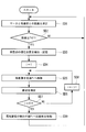
- FIG. 3 is a flowchart for explaining the control contents of the control unit 61 in the “manual alignment mode”.
- the control unit 61 first causes the distance measurement unit 8 to measure the distance between the marker 23 and the electric knife 42 (step SA1). Then, when the measured distance is larger than the predetermined first threshold Th1 (NO in step SA2), the control unit 61 outputs the first sound from a speaker (not shown) with a volume inversely proportional to the distance. (Step SA3). On the other hand, when the measured distance is equal to or less than the predetermined first threshold value Th1 (YES in step SA2), the control unit 61 determines that the second sound is different from the first sound in pitch, tone, melody, and the like.
- step SA4 The controller 61 repeats steps SA1 to SA4 described above while the “manual alignment mode” is selected.
- the first threshold value Th ⁇ b> 1 is set to be smaller than the radius of the movable range of the electric knife 42 driven by the joint portion 43.
- the doctor moves the electric knife 42 arranged outside the body cavity A in the direction in which the first sound increases, thereby arranging the electric knife 42 inside the body cavity A.
- the marker 23 can be approached.
- the doctor moves the first knife from the first sound to the second sound, and the electric knife 42 has a spherical area centered on the marker 23 and having the first threshold Th1 as the radius. Can be recognized.
- FIG. 4 is a flowchart for explaining the control contents of the control unit 61 in the “automatic alignment mode”.
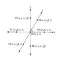
- the control unit 61 first stores the current position of the electric knife 42 relative to the torso 41 (step SB1), and sets the current position to the reference position P0.
- the electric knife 42 is moved (step SB3), and the distance measurement unit 8 is made to measure the distance at each position (distance measurement step SB4).
- the measured distance is stored in the storage unit 62 in association with the position Pi.
- step SB2 After the measurement of the distances at all the positions Pi is completed (steps SB2, SB5, SB6), the control unit 61 sets the position at which the shortest distance is measured among all the distances stored in the storage unit 62 as the closest position. And the electric knife 42 is placed again at the closest position (treatment section moving step SB7). Then, the closest position is set to a new reference position P0, and the above-described steps SB1 to SB6 are repeated (NO in step SB8).
- the second threshold Th2 is equal to or slightly larger than the thickness of the cavity wall B (for example, the thickness of the cavity wall B + several mm). That is, in the “automatic alignment mode”, as shown in FIG. 6B, the electric knife 42 is disposed substantially opposite to the marker 23 through the cavity wall B, and the distance to the marker 23 is minimized. Eventually it will be positioned.
- the switching from the “manual alignment mode” to the “automatic alignment mode” may be automatically performed by the control unit 61. That is, when the distance measured by the distance measuring unit 8 in the “manual alignment mode” is equal to or less than the predetermined first threshold Th1, the control unit 61 forcibly ends the “manual alignment mode”. Then, the “automatic alignment mode” may be started.
- the doctor In order to excise the lesioned part C existing on the inner wall of the body cavity A using the surgical system 1 according to the present embodiment, the doctor first inserts the laparoscope 3 and the treatment tool 4 into the body percutaneously, The scalpel 42 is placed outside the body cavity A, and the laparoscope 3 is placed at a position where the scalpel 42 can be observed. Further, the doctor inserts the endoscope 2 into the body cavity A, observes the lesioned part C with an endoscope image, determines an incision line surrounding the lesioned part C, and positions the marker 23 on the incision line.
- the doctor activates the “manual alignment mode”.
- the electric knife 42 When the electric knife 42 is disposed at a position away from the marker 23, a small first sound is output.
- the doctor operates the operation input device 5 to move the electric knife 42 in the direction in which the first sound increases, and searches for a region where the first sound changes to the second sound. Then, the electric knife 42 is positioned at a position where the second sound is output. As a result, the electric knife 42 is roughly positioned with respect to the marker 23.
- the doctor activates the “automatic alignment mode”. Thereafter, the electric knife 42 is positioned at a position substantially opposite to the marker 23 via the cavity wall B by driving the joint portion 43 by the control unit 61. The doctor cuts the cavity wall B with the electric knife 42 at the finally positioned position. Thereafter, the doctor moves the marker 23 along the incision line and positions the electric knife 42 in two stages of “manual alignment mode” and “automatic alignment mode” to incise the cavity wall B. repeat. Thereby, the cavity wall B is cut along the incision line determined first, and the lesioned part C can be excised.
- a desired incision position is marked with the marker 23, and the electric knife 42 with respect to the incision position is automatically controlled to finely align the electric knife 42 with the marker 23.
- the doctor can incise the cavity wall B along the ideal incision line determined based on the endoscopic image and can minimize the resection range of the cavity wall B. .
- a contact detection unit that detects contact between the electric knife 42 and the tissue.
- the tissue contact portion is composed of, for example, a conductive sensor that electrically detects contact between the electric knife 42 and the tissue.
- the control unit 61 stops measuring the distance at the position Pi and moves to the measurement at the next position Pi + 1, or The distance is measured at a position where the electric knife 42 does not contact the tissue. By doing in this way, it can prevent that the electric knife 42 contacts a structure
- the treatment instrument 4 and the treatment instrument inserted into the channel 24 of the endoscope 2 constitute a bipolar type electrosurgical electrode and are provided at the distal end of the treatment instrument on the endoscope 2 side. Only when the distance between the marked marker 23 and the treatment instrument 4 is equal to or less than the second threshold Th2, the supply of the high-frequency current to the electrode may be permitted. Even in this way, the doctor can cut only the position determined by the doctor.
- control unit 61 has the “lesion site avoidance mode (marker portion avoidance mode)” in addition to the “manual alignment mode” and the “automatic alignment mode”. Different from the embodiment. Therefore, in the present embodiment, the “lesional part avoidance mode” will be mainly described, and the description of the configuration common to the first embodiment will be omitted.
- the “manual alignment mode”, “automatic alignment mode”, and “lesioned part avoidance mode” can be alternatively selected by a doctor using a switch or the like provided in the controller 6. Yes.
- FIG. 7 is a flowchart for explaining the control contents of the control unit 61 in the “lesion site avoidance mode”.
- the “lesion avoidance mode” is used after the positioning of the electric knife 42 with respect to the marker 23 in the “automatic alignment mode” is completed.
- the control unit 61 firstly performs the treatment unit. 42 is stored (step SC1). Normally, the position stored at this time is a position substantially opposed to the marker 23 via the cavity wall B finally determined in the “automatic alignment mode” as shown in FIG. 8A. Therefore, the control unit 61 can obtain the position of the marker 23 from the current position of the electric knife 42 and the second threshold Th2.
- the controller 61 causes the doctor to input a radius (predetermined second threshold) L via the operation input device 5 (step SC2).
- the radius L is a radius of a prohibited area where the placement of the electric knife 42 is prohibited.
- the control unit 61 moves the electric knife 42 to the outside of the prohibited area having the radius L with the position of the marker 23 as the center (step SC3). Thereafter, the control unit 61 permits the operation of the electric knife 42 by the doctor through the operation input device 5 (step SC4).
- the control unit 61 measures the distance between the movement destination of the electric knife 42 input by the doctor to the operation input device 5 and the marker 23 by calculation, and compares the obtained distance with the radius L to determine the movement destination. It is determined whether or not the area is outside the prohibited area (distance measurement step SC5). When the movement destination of the electric knife 42 is outside the prohibited area (YES in step SC5), the control unit 61 moves the electric knife 42 according to the operator's input (treatment section movement step SC6). On the other hand, when the movement destination of the electric knife 42 is inside the prohibited area (NO in step SC5), the control unit 61 rejects the input and stops the electric knife 42 on the spot (step SC7). At this time, the control unit 61 may notify the doctor that the movement destination of the electric knife 42 is inside the prohibited area.
- the doctor positions the marker 23 at the center of the lesion C as shown in FIG. 8A.
- the doctor places the electric knife 42 at a position substantially opposite to the marker 23 via the cavity wall B by the “manual alignment mode” and the “automatic alignment mode”. Position.
- the doctor activates the “lesioned part avoidance mode” and remotely operates the electric knife 42 using the operation input device 5.
- the doctor can operate the electric knife 42 only outside the forbidden region having the radius L from the center of the lesion site C.
- this embodiment is used when the cavity wall B must be cut at a position avoiding the lesioned part C. Accordingly, there is an advantage that the doctor can cut out the periphery of the lesioned part C and remove the lesioned part C while the lesioned part C is preserved.
- the electric knife 42 when the movement destination of the electric knife 42 input by the doctor to the operation input device 5 is in the prohibited area, the electric knife 42 is moved according to the input instead of stopping the movement of the electric knife 42.
- the supply of the high-frequency current to the electric knife 42 may be prohibited.
- control unit 61 may automatically perform switching from the “manual alignment mode” to the “automatic alignment mode” and from the “automatic alignment mode” to the “lesioned part avoidance mode”. That is, the control unit 61 forcibly ends the “manual alignment mode” when the distance measured by the distance measurement unit 8 in the “automatic alignment mode” is equal to or less than the predetermined first threshold Th1.
- the “automatic alignment mode” may be started, and the “lesioned part avoidance mode” may be started after the “automatic alignment mode” ends.
- FIGS. 9 to 10B a third embodiment of the present embodiment will be described with reference to FIGS. 9 to 10B.
- the present embodiment is different from the first embodiment in that the control unit 61 has a “following mode” instead of the “automatic alignment mode”. Therefore, in the present embodiment, the “follow-up mode” will be mainly described, and the description of the configuration common to the first embodiment will be omitted.
- the “manual alignment mode” and the “follow-up mode” can be alternatively selected by a doctor using a switch or the like provided in the controller 6.
- FIG. 9 is a flowchart for explaining the control content of the control unit 61 in the “follow-up mode”.
- the “follow-up mode” is used after the positioning of the electric knife 42 with respect to the marker 23 in the “manual alignment mode” is completed. After the electric knife 42 is arranged in the region of the radius Th1 centered on the marker 23 by the “manual alignment mode”, when the “manual alignment mode” is switched to the “following mode”, the control unit 61 causes the marker 61 to The distance measurement unit 8 is repeatedly made to measure the distance between the electric knife 23 and the electric knife 42 (distance measurement step SD1).
- Step SD2 the control unit 61 uses the same procedure as in the “automatic alignment mode”, and the distance is equal to or less than the second threshold Th2.
- Step SD3 to SD9 the positioning of the electric knife 42 with respect to the marker 23 is executed. That is, steps SD3 to SD9 in the “following mode” are the same as steps SB2 to SB8 in the “automatic alignment mode”.
- the marker 23 moves once after the control unit 61 positions the electric knife 42 at a position substantially opposite to the marker 23 via the cavity wall B. Then, the control part 61 detects the movement from the increase in the distance between the marker 23 and the electric knife 42, and again, as shown in FIG. 10B, again a position substantially facing the marker 23 via the cavity wall B. Reposition the electric knife 42. Thereby, the electric knife 42 is made to follow the movement of the marker 23.
- the doctor positions the marker 23 on the incision line determined by the doctor, and roughly sets the electric knife 42 relative to the marker 23 in the “manual alignment mode”. Align.
- the doctor activates the “follow-up mode”. Thereby, the electric knife 42 is positioned at a position substantially opposite to the marker 23 via the cavity wall B.
- the electric knife 42 automatically follows the movement of the marker 23. Again, the electric knife 42 is positioned at a position substantially opposite to the marker 23 via the cavity wall B. Thereafter, the doctor repeats the movement of the marker 23 and the incision with the electric knife 42 at the movement destination until the incision at all desired positions is completed.
- the electric knife 42 automatically follows the movement of the marker 23, so that the electric knife 42 is always disposed at a position substantially opposed to the marker 23 via the cavity wall B. . Therefore, there is an advantage that the doctor can incise the cavity wall B along the incision line by moving the marker 23 along the incision line determined by the doctor.
- the endoscope 2 to be inserted into the body cavity A must be flexible, but the flexible endoscope 2 is bent by the pressing force from the cavity wall B. It is difficult to incise the cavity wall B with the treatment tool introduced into the body cavity A. Therefore, the incision can be easily performed by specifying the resection line with the endoscope 2 and using the rigid treatment tool 4 capable of transmitting a force to the cavity wall B.
- the supply of the high-frequency current to the electric knife 42 is permitted only when the distance measured by the distance measuring unit 8 is equal to or less than the second threshold Th2. Good.
- the treatment instrument 4 and the treatment instrument inserted into the channel 24 of the endoscope 2 constitute an electrode of a bipolar electric scalpel 42, and a marker provided at the distal end of the treatment instrument on the endoscope 2 side.
- the supply of the high-frequency current to the electric knife 42 may be permitted only when the distance between the tool 23 and the treatment instrument 4 is equal to or less than the second threshold Th2.
- control unit 61 is configured to be able to selectively select the combination of the three types of modes described in the first to third embodiments. Different from form.
- the control unit 61 has a “first mode”, a “second mode”, and a “third mode”.
- the “first mode” includes a “manual alignment mode” and an “automatic alignment mode”.
- the “second mode” includes a “manual alignment mode” and a “follow-up mode”.
- the “third mode” includes a “manual alignment mode”, an “automatic alignment mode”, and a “lesioned part avoidance mode”.
- the surgical operation system 1 ′ includes a mode selection unit 9 that can alternatively select the first mode, the second mode, and the third mode by a doctor's operation.
- the mode selection unit 9 may be provided in the operation input device 5 or the controller 6.
- first mode is “automatic alignment mode”
- second mode is “follow-up mode”
- third mode is “lesion avoidance mode (marker avoidance mode)”. As long as each of them is included. Further, any two modes among the “first mode”, “second mode”, and “third mode” may be alternatively selectable.
- two or more distance measuring units 8 may be provided at different positions of the electric knife 42.
- the relative position of the electric knife 42 and the marker 23 is obtained by calculation from the distance measured by each distance measuring unit 8.
- the doctor can recognize the position of the marker 23 more accurately by presenting the obtained relative position to the doctor.
- the control unit 61 can cause the electric knife 42 to follow the marker 23 by moving the electric knife 42 by the obtained movement vector. Thereby, the responsiveness of the electric knife 42 with respect to the movement of the marker 23 can be improved.
Abstract
A surgical system (1) which comprises: a first medical instrument (2) that is disposed inside a body cavity and has an observation section (22) and a marking section (23) which is capable of positioning relative to the body cavity; a second medical instrument (4) that is disposed outside the body cavity and has a treatment section (42) and a drive section (44) which drives the treatment section (42); a distance measurement section (8) that measures the distance between the marking section (23) and the treatment section (42); and a control section (61) that controls the drive section (44) on the basis of the distance that has been measured by the distance measurement section (8).
Description
本発明は、手術システムおよび手術システムの作動方法に関するものである。
The present invention relates to a surgical system and a method for operating the surgical system.
従来、腹腔鏡と内視鏡とを使用し、体腔の内側と外側の両方から手術範囲を観察しながら手術を行う腹腔鏡内視鏡合同手術(LECS;Laparoscopy endoscopy cooperative surgery)が知られている(例えば、特許文献1参照。)。例えば、胃の内壁に存在する病変部を切除する場合、病変部を胃の内側から内視鏡で観察することによって切除線を決定し、決定した切除線に沿って胃の外側から胃壁をメス等の処置具で切開することによって、切除範囲を最小限に抑えることができる。
Conventionally, laparoscopic endoscopic surgery (LECS) has been known in which surgery is performed using a laparoscope and an endoscope while observing the surgical area from both inside and outside the body cavity. (For example, refer to Patent Document 1). For example, when resecting a lesion existing on the inner wall of the stomach, the resection line is determined by observing the lesion from the inside of the stomach with an endoscope, and the stomach wall is measured from the outside of the stomach along the determined resection line. The incision range can be minimized by making an incision with a treatment tool such as the above.
このLECSにおいて、医師は、体腔内の内視鏡の位置に基づいて切除線の位置を判断することになるため、体腔内の内視鏡の正確な位置を知ることが重要である。そこで、特許文献1は、内視鏡の先端に磁石またはLEDを設け、磁石からの磁界またはLEDからの光を体腔外で検出することによって、体腔内の内視鏡の位置を検出可能としている。
In this LECS, since the doctor determines the position of the resection line based on the position of the endoscope in the body cavity, it is important to know the exact position of the endoscope in the body cavity. Therefore, in Patent Document 1, a magnet or LED is provided at the distal end of the endoscope, and the position of the endoscope in the body cavity can be detected by detecting the magnetic field from the magnet or the light from the LED outside the body cavity. .
しかしながら、例えば体腔内壁に形成されるポリープの径は20mmから50mm程度であり、切除範囲を最小限に抑えるためには、決定した切除線に対してミリ単位の位置精度で処置具を位置決めすることが要求される。したがって、特許文献1のように、検出された内視鏡の位置に基づいて医師が手動で処置具を位置決めする場合には、医師に非常に高い技量が要求される。特に、特許文献1において、医師は、磁界の強度に応じて出力される音や、LEDからの光の明るさを頼りに体腔内の内視鏡の位置を特定しなければならない。このように、医師の感覚に基づいて処置具の配置すべき位置を決定する方法は、医師に大きな負担をかけることになると共に、処置具の正確な位置決めが難しいという問題がある。
However, for example, the diameter of the polyp formed on the inner wall of the body cavity is about 20 mm to 50 mm, and in order to minimize the excision range, the treatment tool is positioned with a positional accuracy in millimeters with respect to the determined excision line. Is required. Accordingly, when the doctor manually positions the treatment tool based on the detected position of the endoscope as in Patent Document 1, a very high skill is required of the doctor. In particular, in Patent Document 1, a doctor must specify the position of an endoscope in a body cavity based on the sound output according to the strength of the magnetic field and the brightness of light from the LED. As described above, the method of determining the position where the treatment tool is to be arranged based on the sense of the doctor places a heavy burden on the doctor and there is a problem that it is difficult to accurately position the treatment tool.
本発明は、上述した事情に鑑みてなされたものであって、体腔を内側と外側の両方から観察しながら処置するLECSにおいて、内側から観察して決定した体腔の処置位置に対して処置具を正確に外側から位置決めし、決定した処置位置を正確に処置することができる手術システムおよび手術システムの作動方法を提供することを目的とする。
The present invention has been made in view of the above-described circumstances, and in LECS that treats a body cavity while observing it from both inside and outside, the treatment tool is attached to the treatment position of the body cavity determined by observing from the inside. It is an object of the present invention to provide a surgical system and a method for operating the surgical system that can be accurately positioned from the outside and can accurately treat the determined treatment position.
上記目的を達成するため、本発明は以下の手段を提供する。
本発明の第1の態様は、体腔の内側に配置され、前記体腔を観察する観察部と、前記体腔に対して位置決め可能な標識部とを有する第1の医療器具と、前記体腔の外側に配置され、前記体腔に対して処置を施す処置部と、該処置部を駆動する駆動部とを有する第2の医療器具と、前記標識部と前記処置部との間の距離を測定する距離測定部と、該距離測定部によって測定された距離に基づいて前記駆動部を制御する制御部とを備える手術システムである。 In order to achieve the above object, the present invention provides the following means.
According to a first aspect of the present invention, there is provided a first medical instrument that is disposed inside a body cavity, has an observation unit that observes the body cavity, and a marker that can be positioned with respect to the body cavity, and an outer side of the body cavity. Distance measurement that measures the distance between the second medical instrument that is disposed and has a treatment part that performs treatment on the body cavity, and a drive part that drives the treatment part, and the marker part and the treatment part And a control unit that controls the drive unit based on the distance measured by the distance measurement unit.
本発明の第1の態様によれば、体腔内に位置する第1の医療器具の標識部と、体腔外に位置する第2の医療器具の処置部との間の距離に基づき、制御部が、駆動部を制御することによって処置部を移動させる。したがって、観察部によって観察される体腔内の画像に基づいて特定した病変部等の処置位置に標識部を位置決めすることによって、処置位置に対して腔壁を介した適切な位置に処置部を配置することができる。
According to the first aspect of the present invention, based on the distance between the marking portion of the first medical instrument located inside the body cavity and the treatment portion of the second medical instrument located outside the body cavity, the control unit is The treatment unit is moved by controlling the drive unit. Therefore, by positioning the marker part at the treatment position such as a lesion part specified based on the image in the body cavity observed by the observation part, the treatment part is arranged at an appropriate position via the cavity wall with respect to the treatment position. can do.
このように、処置位置に対する処置部の位置合わせを自動化することにより、処置部の高精度な位置合わせが可能となる。これにより、内側から観察して決定した体腔の処置位置に対して処置具を正確に外側から位置決めし、決定した処置位置を正確に処置することができる。
Thus, by automating the alignment of the treatment section with respect to the treatment position, the treatment section can be positioned with high accuracy. Accordingly, the treatment tool can be accurately positioned from the outside with respect to the treatment position of the body cavity that is determined by observation from the inside, and the determined treatment position can be accurately treated.
上記第1の態様においては、前記距離が所定の第1の閾値以下となる位置に前記処置部を位置決めするように、前記駆動部を制御してもよい。
このようにすることで、所定の第1の閾値を十分に小さい値(例えば、腔壁の厚さ寸法と略同等の値)に設定することによって、処置部を、腔壁を介して標識部と略対向する位置に位置決めすることができる。これにより、体腔内の病変部の位置を体腔外から正確に認識することができる。 In the first aspect, the drive unit may be controlled so that the treatment unit is positioned at a position where the distance is equal to or less than a predetermined first threshold value.
In this way, by setting the predetermined first threshold value to a sufficiently small value (for example, a value approximately equivalent to the thickness dimension of the cavity wall), the treatment section is placed through the cavity wall. It can be positioned at a position substantially opposite to. Thereby, the position of the lesioned part in the body cavity can be accurately recognized from outside the body cavity.
上記第1の態様においては、前記距離測定部が、前記距離を繰り返し測定し、前記制御部は、前記距離測定部によって測定された距離が前記所定の第1の閾値を超える毎に、前記距離が前記所定の第1の閾値以下となる位置に前記処置部を位置決めし直すように、前記駆動部を繰り返し駆動させてもよい。
このようにすることで、標識部が移動すると、制御部は、距離測定部によって測定される距離の増加としてその旨を検知し、駆動部を制御することによって、移動後の標識部と腔壁を介して略対向する位置に処置部を再び位置決めする。このようにして標識部の移動に処置部を追従させることによって、標識部の軌跡に沿って組織を処置することができる。 In the first aspect, the distance measurement unit repeatedly measures the distance, and the control unit measures the distance every time the distance measured by the distance measurement unit exceeds the predetermined first threshold. The drive unit may be repeatedly driven so that the treatment unit is repositioned at a position where the value is equal to or less than the predetermined first threshold value.
In this way, when the marker part moves, the control unit detects that as an increase in the distance measured by the distance measuring unit, and controls the driving unit to move the marker part and cavity wall after the movement. Then, the treatment part is positioned again at a position substantially opposite to each other. In this way, by causing the treatment portion to follow the movement of the marker portion, the tissue can be treated along the locus of the marker portion.
上記第1の態様においては、前記制御部は、前記距離が所定の第2の閾値よりも大きくなる位置に前記処置部が配置されるように、前記駆動部を制御してもよい。
このようにすることで、標識部を中心とし、所定の第2の閾値を半径とする球状の領域の外側でのみ処置部の移動が許可される。これにより、例えば、病変部の切除のような、病変部の内側ではなく病変部の外側を処置する手技において、病変部の中央に標識部を位置決めしておくことによって、病変部を保存したまま、処置を行うことができる。 In the first aspect, the control unit may control the driving unit such that the treatment unit is disposed at a position where the distance is greater than a predetermined second threshold.
By doing in this way, the movement of the treatment part is permitted only outside the spherical area centered on the sign part and having a predetermined second threshold as a radius. Thus, for example, in a procedure for treating the outside of the lesion rather than the inside of the lesion, such as excision of the lesion, the lesion is preserved by positioning the marker at the center of the lesion. , Treatment can be performed.
上記第1の態様においては、前記制御部は、前記距離が所定の第1の閾値以下となる位置に前記処置部を位置決めするように、前記駆動部を制御する自動位置合わせモードを含む第1のモードと、前記距離測定部によって測定された距離が所定の第1の閾値を超える毎に、前記距離が前記所定の第1の閾値以下となる位置に前記処置部を位置決めし直すように、前記駆動部を繰り返し駆動する追従モードを含む第2のモードと、前記距離が前記所定の第1の閾値よりも大きい所定の第2の閾値よりも大きくなる位置に前記処置部が配置されるように、前記駆動部を制御する標識部回避モードを含む第3のモードとを有し、前記第1のモード、前記第2のモードおよび前記第3のモードを、操作者に択一的に選択させるモード選択部を備えていてもよい。
このようにすることで、処置の内容やそのときの状況等に最適なモードを操作者がモード選択部を用いて選択することができる。 In the first aspect, the control unit includes an automatic alignment mode for controlling the drive unit so as to position the treatment unit at a position where the distance is equal to or less than a predetermined first threshold value. Each time the distance measured by the distance measuring unit exceeds a predetermined first threshold value, the treatment unit is repositioned at a position where the distance is equal to or less than the predetermined first threshold value. The treatment section is arranged in a second mode including a follow-up mode in which the driving section is repeatedly driven and a position where the distance is larger than a predetermined second threshold value that is larger than the predetermined first threshold value. And a third mode including a sign section avoidance mode for controlling the driving section, and the first mode, the second mode, and the third mode are alternatively selected by an operator. It has a mode selection section It may be.
By doing in this way, an operator can select the mode most suitable for the content of treatment, the situation at that time, etc. using a mode selection part.
本発明の第2の態様は、体腔の内側に位置決めされた標識部と、前記体腔の外側に配置された医療器具の処置部との間の距離を測定する距離測定ステップと、該距離測定ステップにおいて測定された距離に基づいて前記処置部を移動させる処置部移動ステップとを含む手術システムの作動方法を提供する。
According to a second aspect of the present invention, there is provided a distance measuring step for measuring a distance between a marker portion positioned inside a body cavity and a treatment portion of a medical instrument disposed outside the body cavity, and the distance measuring step And a treatment portion moving step of moving the treatment portion based on the distance measured in step (b).
本発明によれば、体腔を内側と外側の両方から観察しながら処置するLECSにおいて、内側から観察して決定した体腔の処置位置に対して処置具を正確に外側から位置決めし、決定した処置位置を正確に処置することができるという効果を奏する。
According to the present invention, in LECS which treats while observing the body cavity from both inside and outside, the treatment tool is accurately positioned from the outside with respect to the treatment position of the body cavity determined by observing from the inside, and the determined treatment position There is an effect that can be accurately treated.
(第1の実施形態)
以下に、本発明の第1の実施形態に係る手術システム1について図1から図6Bを参照して説明する。
本実施形態に係る手術システム1は、図1に示されるように、内視鏡2と腹腔鏡3とを用いて体腔Aを内側と外側の両方から観察しながら、体腔Aを外側から処置する腹腔鏡内視鏡合同手術(LECS)に使用されるものである。 (First embodiment)
Below, thesurgery system 1 which concerns on the 1st Embodiment of this invention is demonstrated with reference to FIGS. 1-6B.
As shown in FIG. 1, thesurgical system 1 according to the present embodiment treats a body cavity A from the outside while observing the body cavity A from both the inside and the outside using an endoscope 2 and a laparoscope 3. It is used for laparoscopic combined surgery (LECS).
以下に、本発明の第1の実施形態に係る手術システム1について図1から図6Bを参照して説明する。
本実施形態に係る手術システム1は、図1に示されるように、内視鏡2と腹腔鏡3とを用いて体腔Aを内側と外側の両方から観察しながら、体腔Aを外側から処置する腹腔鏡内視鏡合同手術(LECS)に使用されるものである。 (First embodiment)
Below, the
As shown in FIG. 1, the
具体的には、手術システム1は、図2に示されるように、内視鏡2と、腹腔鏡3と、処置具4と、医師(操作者)によって操作れる操作入力装置5と、該操作入力装置5への入力に基づいて処置具4を制御するコントローラ6とを備えている。
内視鏡2は、体腔A内に挿入可能な細長い軟性の挿入部21と、該挿入部21の先端に内蔵された撮像素子(観察部)22とを備え、該撮像素子22によって取得した体腔A内の映像をモニタ7に送信する。 Specifically, as shown in FIG. 2, thesurgical system 1 includes an endoscope 2, a laparoscope 3, a treatment instrument 4, an operation input device 5 operated by a doctor (operator), and the operation And a controller 6 that controls the treatment instrument 4 based on an input to the input device 5.
Theendoscope 2 includes an elongated flexible insertion portion 21 that can be inserted into the body cavity A, and an imaging element (observation unit) 22 built in the distal end of the insertion portion 21, and the body cavity acquired by the imaging element 22. The video in A is transmitted to the monitor 7.
内視鏡2は、体腔A内に挿入可能な細長い軟性の挿入部21と、該挿入部21の先端に内蔵された撮像素子(観察部)22とを備え、該撮像素子22によって取得した体腔A内の映像をモニタ7に送信する。 Specifically, as shown in FIG. 2, the
The
内視鏡2は、体腔Aの内側から外側へ腔壁Bを介して伝搬する信号(例えば、磁界、光、熱、電圧)を発生するマーカ(標識部)23を有している。マーカ23は、例えば、挿入部21に長手方向に沿って貫通形成されたチャネル24内に長手方向に移動可能に挿入されたワイヤ25の先端に設けられている。医師は、ワイヤ25の基端部分を操作することによって体腔A内でマーカ23を移動させることができ、ワイヤ25を挿入部21に対して固定することによって体腔Aの内壁に対してマーカ23を位置決めすることができる。ワイヤ25に代えて、チャネル24内に挿入可能な任意の処置具を用いてもよい。
The endoscope 2 has a marker (marking unit) 23 that generates a signal (for example, a magnetic field, light, heat, voltage) that propagates through the cavity wall B from the inside to the outside of the body cavity A. The marker 23 is provided, for example, at the tip of a wire 25 that is movably inserted in the longitudinal direction in a channel 24 that is formed through the insertion portion 21 along the longitudinal direction. The doctor can move the marker 23 in the body cavity A by operating the proximal end portion of the wire 25, and can fix the marker 23 to the inner wall of the body cavity A by fixing the wire 25 to the insertion portion 21. Can be positioned. Instead of the wire 25, any treatment instrument that can be inserted into the channel 24 may be used.
腹腔鏡3は、経皮的に体内に挿入可能であり、取得した体内の映像をモニタ7に送信する。
処置具4は、経皮的に体内に挿入可能な細長い硬性の胴部41と、該胴部41の先端側に設けられ組織に対して処置を施す処置部42と、胴部41と処置部42とを連結する関節部43と、該関節部43を駆動する駆動部44とを備えている。本実施形態においては、処置部42として電気メス(以下、電気メス42ともいう。)を備える場合について説明するが、処置部42は、鉗子やハサミ等の他の種類のものであってもよい。 Thelaparoscope 3 can be inserted into the body percutaneously, and transmits the acquired image inside the body to the monitor 7.
Thetreatment instrument 4 includes an elongated rigid body portion 41 that can be inserted into the body percutaneously, a treatment portion 42 that is provided on the distal end side of the body portion 41 and that treats tissue, and the body portion 41 and the treatment portion. And a drive unit 44 that drives the joint unit 43. In the present embodiment, a case where an electric knife (hereinafter also referred to as an electric knife 42) is provided as the treatment section 42 will be described. However, the treatment section 42 may be other types such as forceps and scissors. .
処置具4は、経皮的に体内に挿入可能な細長い硬性の胴部41と、該胴部41の先端側に設けられ組織に対して処置を施す処置部42と、胴部41と処置部42とを連結する関節部43と、該関節部43を駆動する駆動部44とを備えている。本実施形態においては、処置部42として電気メス(以下、電気メス42ともいう。)を備える場合について説明するが、処置部42は、鉗子やハサミ等の他の種類のものであってもよい。 The
The
電気メス42には、マーカ23が発生する信号を検出することによって、電気メス42とマーカ23との間の距離を測定する距離測定部8が設けられている。
ここで、マーカ23と距離測定部8との組み合わせとしては、例えば、磁石(永久磁石または電磁石)とホール素子またはコイル、近赤外レーザ光源と光検出器、投光器と受光器、発熱素子と熱検出器、交流電圧発生素子とインピーダンス検出器等が挙げられる。このように、距離測定部8は、磁気または光の強度、温度、あるいはインピーダンスの大きさを検出し、得られた検出値に基づいて、腔壁Bを介して配置されたマーカ23と電気メス42との距離を測定する。 Theelectric knife 42 is provided with a distance measuring unit 8 that measures a distance between the electric knife 42 and the marker 23 by detecting a signal generated by the marker 23.
Here, as a combination of themarker 23 and the distance measuring unit 8, for example, a magnet (permanent magnet or electromagnet) and a Hall element or coil, a near infrared laser light source and a light detector, a projector and a light receiver, a heating element and a heat are used. Examples include a detector, an AC voltage generating element, and an impedance detector. Thus, the distance measuring unit 8 detects the intensity of magnetism or light, temperature, or impedance, and based on the obtained detection value, the marker 23 and the electric knife arranged via the cavity wall B The distance to 42 is measured.
ここで、マーカ23と距離測定部8との組み合わせとしては、例えば、磁石(永久磁石または電磁石)とホール素子またはコイル、近赤外レーザ光源と光検出器、投光器と受光器、発熱素子と熱検出器、交流電圧発生素子とインピーダンス検出器等が挙げられる。このように、距離測定部8は、磁気または光の強度、温度、あるいはインピーダンスの大きさを検出し、得られた検出値に基づいて、腔壁Bを介して配置されたマーカ23と電気メス42との距離を測定する。 The
Here, as a combination of the
関節部43は、胴部41の長手方向に交差する2次元方向に揺動可能に電気メス42を支持している。
駆動部44は、コントローラ6から受信した制御信号に基づいて関節部43を駆動し、それによって電気メス42を胴部41の長手方向に交差する2次元方向に移動させる。
操作入力装置5は、医師によってなされた操作に対応する操作信号を生成し、生成した操作信号をコントローラ6に送信する。 Thejoint portion 43 supports the electric knife 42 so as to be swingable in a two-dimensional direction intersecting the longitudinal direction of the body portion 41.
Thedrive unit 44 drives the joint unit 43 based on the control signal received from the controller 6, thereby moving the electric knife 42 in a two-dimensional direction intersecting the longitudinal direction of the body unit 41.
Theoperation input device 5 generates an operation signal corresponding to the operation performed by the doctor, and transmits the generated operation signal to the controller 6.
駆動部44は、コントローラ6から受信した制御信号に基づいて関節部43を駆動し、それによって電気メス42を胴部41の長手方向に交差する2次元方向に移動させる。
操作入力装置5は、医師によってなされた操作に対応する操作信号を生成し、生成した操作信号をコントローラ6に送信する。 The
The
The
コントローラ6は、内視鏡2および処置具4を制御する制御部61と、記憶部62とを備えている。
制御部61は、操作入力装置5を介した処置具4の操作を許可し、医師によって操作入力装置5に入力された操作に従って駆動部44を制御する「手動位置合わせモード」と、操作入力装置5を介した処置具4の操作を禁止し、距離測定部8によって測定される距離に基づいて駆動部44を制御する「自動位置合わせモード」とを有している。これら2つのモードは、コントローラ6に設けられたスイッチ等を用いて医師によって択一的に選択可能になっている。
次に、この「手動位置合わせモード」と「自動位置合わせモード」とについて、詳細に説明する。 Thecontroller 6 includes a control unit 61 that controls the endoscope 2 and the treatment instrument 4, and a storage unit 62.
Thecontrol unit 61 permits the operation of the treatment instrument 4 via the operation input device 5 and controls the drive unit 44 according to the operation input to the operation input device 5 by the doctor, and the operation input device. 5 has an “automatic alignment mode” in which the operation of the treatment instrument 4 via 5 is prohibited and the drive unit 44 is controlled based on the distance measured by the distance measuring unit 8. These two modes can be alternatively selected by a doctor using a switch or the like provided in the controller 6.
Next, the “manual alignment mode” and the “automatic alignment mode” will be described in detail.
制御部61は、操作入力装置5を介した処置具4の操作を許可し、医師によって操作入力装置5に入力された操作に従って駆動部44を制御する「手動位置合わせモード」と、操作入力装置5を介した処置具4の操作を禁止し、距離測定部8によって測定される距離に基づいて駆動部44を制御する「自動位置合わせモード」とを有している。これら2つのモードは、コントローラ6に設けられたスイッチ等を用いて医師によって択一的に選択可能になっている。
次に、この「手動位置合わせモード」と「自動位置合わせモード」とについて、詳細に説明する。 The
The
Next, the “manual alignment mode” and the “automatic alignment mode” will be described in detail.
図3は、「手動位置合わせモード」における制御部61の制御内容を説明するフローチャートである。
医師によって「手動位置合わせモード」が選択されると、制御部61は、まず、距離測定部8にマーカ23と電気メス42との間の距離を測定させる(ステップSA1)。そして、制御部61は、測定された距離が所定の第1の閾値Th1よりも大きい場合には(ステップSA2のNO)、第1の音を、距離に反比例する音量で図示しないスピーカから出力させる(ステップSA3)。一方、制御部61は、測定された距離が所定の第1の閾値Th1以下である場合には(ステップSA2のYES)、第1の音とは高さや音色、旋律等が異なる第2の音を出力させる(ステップSA4)。制御部61は、「手動位置合わせモード」が選択されている間、上述したステップSA1からSA4を繰り返す。ここで、第1の閾値Th1は、電気メス42の、関節部43の駆動による可動範囲の半径よりも小さく設定される。 FIG. 3 is a flowchart for explaining the control contents of thecontrol unit 61 in the “manual alignment mode”.
When the “manual alignment mode” is selected by the doctor, thecontrol unit 61 first causes the distance measurement unit 8 to measure the distance between the marker 23 and the electric knife 42 (step SA1). Then, when the measured distance is larger than the predetermined first threshold Th1 (NO in step SA2), the control unit 61 outputs the first sound from a speaker (not shown) with a volume inversely proportional to the distance. (Step SA3). On the other hand, when the measured distance is equal to or less than the predetermined first threshold value Th1 (YES in step SA2), the control unit 61 determines that the second sound is different from the first sound in pitch, tone, melody, and the like. Is output (step SA4). The controller 61 repeats steps SA1 to SA4 described above while the “manual alignment mode” is selected. Here, the first threshold value Th <b> 1 is set to be smaller than the radius of the movable range of the electric knife 42 driven by the joint portion 43.
医師によって「手動位置合わせモード」が選択されると、制御部61は、まず、距離測定部8にマーカ23と電気メス42との間の距離を測定させる(ステップSA1)。そして、制御部61は、測定された距離が所定の第1の閾値Th1よりも大きい場合には(ステップSA2のNO)、第1の音を、距離に反比例する音量で図示しないスピーカから出力させる(ステップSA3)。一方、制御部61は、測定された距離が所定の第1の閾値Th1以下である場合には(ステップSA2のYES)、第1の音とは高さや音色、旋律等が異なる第2の音を出力させる(ステップSA4)。制御部61は、「手動位置合わせモード」が選択されている間、上述したステップSA1からSA4を繰り返す。ここで、第1の閾値Th1は、電気メス42の、関節部43の駆動による可動範囲の半径よりも小さく設定される。 FIG. 3 is a flowchart for explaining the control contents of the
When the “manual alignment mode” is selected by the doctor, the
「手動位置合わせモード」において、医師は、体腔Aの外側に配置した電気メス42を第1の音が大きくなる方向へ移動させることによって、当該電気メス42を体腔Aの内側に配置されているマーカ23へ接近させることができる。そして、医師は、第1の音から第2の音への変化によって、図6Aに示されるように、電気メス42が、マーカ23を中心とし、第1の閾値Th1を半径とする球状の領域内に配置されたことを認識することができる。
In the “manual alignment mode”, the doctor moves the electric knife 42 arranged outside the body cavity A in the direction in which the first sound increases, thereby arranging the electric knife 42 inside the body cavity A. The marker 23 can be approached. Then, as shown in FIG. 6A, the doctor moves the first knife from the first sound to the second sound, and the electric knife 42 has a spherical area centered on the marker 23 and having the first threshold Th1 as the radius. Can be recognized.
図4は、「自動位置合わせモード」における制御部61の制御内容を説明するフローチャートである。
医師によって「自動位置合わせモード」が選択されると、制御部61は、まず、胴部41に対する電気メス42の現在位置を記憶し(ステップSB1)、現在位置を基準位置P0に設定する。次に、制御部61は、図5に示されるように、基準位置P0を基準とする複数(本例においては6個)の所定の位置Pi(i=1,2,3,…,6)に電気メス42を移動させ(ステップSB3)、各位置における距離を距離測定部8に測定させる(距離測定ステップSB4)。測定された距離は、その位置Piと対応づけて記憶部62に記憶される。 FIG. 4 is a flowchart for explaining the control contents of thecontrol unit 61 in the “automatic alignment mode”.
When the “automatic alignment mode” is selected by the doctor, thecontrol unit 61 first stores the current position of the electric knife 42 relative to the torso 41 (step SB1), and sets the current position to the reference position P0. Next, as shown in FIG. 5, the control unit 61 has a plurality of (six in this example) predetermined positions Pi (i = 1, 2, 3,..., 6) with reference to the reference position P0. Then, the electric knife 42 is moved (step SB3), and the distance measurement unit 8 is made to measure the distance at each position (distance measurement step SB4). The measured distance is stored in the storage unit 62 in association with the position Pi.
医師によって「自動位置合わせモード」が選択されると、制御部61は、まず、胴部41に対する電気メス42の現在位置を記憶し(ステップSB1)、現在位置を基準位置P0に設定する。次に、制御部61は、図5に示されるように、基準位置P0を基準とする複数(本例においては6個)の所定の位置Pi(i=1,2,3,…,6)に電気メス42を移動させ(ステップSB3)、各位置における距離を距離測定部8に測定させる(距離測定ステップSB4)。測定された距離は、その位置Piと対応づけて記憶部62に記憶される。 FIG. 4 is a flowchart for explaining the control contents of the
When the “automatic alignment mode” is selected by the doctor, the
全ての位置Piにおける距離の測定が終了した後(ステップSB2,SB5,SB6)、制御部61は、記憶部62に記憶されている全ての距離のうち最短距離が測定された位置を最近接位置として選択し、最近接位置に再び電気メス42を配置する(処置部移動ステップSB7)。そして、最近接位置を新たな基準位置P0に設定し、上述したステップSB1からSB6を繰り返す(ステップSB8のNO)。
After the measurement of the distances at all the positions Pi is completed (steps SB2, SB5, SB6), the control unit 61 sets the position at which the shortest distance is measured among all the distances stored in the storage unit 62 as the closest position. And the electric knife 42 is placed again at the closest position (treatment section moving step SB7). Then, the closest position is set to a new reference position P0, and the above-described steps SB1 to SB6 are repeated (NO in step SB8).
ただし、前記最短距離が所定の第2の閾値(所定の第1の閾値)Th2以下である場合には(ステップSB8のYES)、最近接位置に電気メス42を配置した後(ステップSB7)、医師に対して電気メス42の移動の完了を通知して「自動位置合わせモード」を終了する(ステップSB9)。ここで、第2の閾値Th2は、腔壁Bの厚さと同等かそれよりもわずかに大きい値(例えば、腔壁Bの厚さ+数mm)である。すなわち、「自動位置合わせモード」により、電気メス42は、図6Bに示されるように、腔壁Bを介してマーカ23と略対向して配置され、マーカ23までの距離が最小となる位置に最終的に位置決めされることになる。
However, when the shortest distance is equal to or less than the predetermined second threshold (predetermined first threshold) Th2 (YES in Step SB8), after the electric knife 42 is disposed at the closest position (Step SB7), The completion of the movement of the electric knife 42 is notified to the doctor, and the “automatic alignment mode” is ended (step SB9). Here, the second threshold Th2 is equal to or slightly larger than the thickness of the cavity wall B (for example, the thickness of the cavity wall B + several mm). That is, in the “automatic alignment mode”, as shown in FIG. 6B, the electric knife 42 is disposed substantially opposite to the marker 23 through the cavity wall B, and the distance to the marker 23 is minimized. Eventually it will be positioned.
「手動位置合わせモード」から「自動位置合わせモード」への切り替えは、制御部61が自動で行ってもよい。すなわち、「手動位置合わせモード」において距離測定部8によって測定された距離が所定の第1の閾値Th1以下であったときに、制御部61は、「手動位置合わせモード」を強制的に終了して「自動位置合わせモード」を開始してもよい。
The switching from the “manual alignment mode” to the “automatic alignment mode” may be automatically performed by the control unit 61. That is, when the distance measured by the distance measuring unit 8 in the “manual alignment mode” is equal to or less than the predetermined first threshold Th1, the control unit 61 forcibly ends the “manual alignment mode”. Then, the “automatic alignment mode” may be started.
次に、このように構成された手術システム1の作用について説明する。
本実施形態に係る手術システム1を用いて体腔Aの内壁に存在する病変部Cを切除するには、まず、医師は、腹腔鏡3および処置具4を経皮的に体内に挿入し、電気メス42を体腔Aの外側に配置するとともに、電気メス42を観察可能な位置に腹腔鏡3を配置する。また、医師は、体腔A内に内視鏡2を挿入し、病変部Cを内視鏡映像で観察して病変部Cを取り囲む切開線を決定し、切開線上にマーカ23を位置決めする。 Next, the operation of thesurgical system 1 configured as described above will be described.
In order to excise the lesioned part C existing on the inner wall of the body cavity A using thesurgical system 1 according to the present embodiment, the doctor first inserts the laparoscope 3 and the treatment tool 4 into the body percutaneously, The scalpel 42 is placed outside the body cavity A, and the laparoscope 3 is placed at a position where the scalpel 42 can be observed. Further, the doctor inserts the endoscope 2 into the body cavity A, observes the lesioned part C with an endoscope image, determines an incision line surrounding the lesioned part C, and positions the marker 23 on the incision line.
本実施形態に係る手術システム1を用いて体腔Aの内壁に存在する病変部Cを切除するには、まず、医師は、腹腔鏡3および処置具4を経皮的に体内に挿入し、電気メス42を体腔Aの外側に配置するとともに、電気メス42を観察可能な位置に腹腔鏡3を配置する。また、医師は、体腔A内に内視鏡2を挿入し、病変部Cを内視鏡映像で観察して病変部Cを取り囲む切開線を決定し、切開線上にマーカ23を位置決めする。 Next, the operation of the
In order to excise the lesioned part C existing on the inner wall of the body cavity A using the
次に、医師は、「手動位置合わせモード」を起動する。電気メス42がマーカ23から離れた位置に配置されているときには、小さな第1の音が出力される。医師は、操作入力装置5を操作することによって、第1の音が大きくなる方向へ電気メス42を移動させ、第1の音が第2の音へ変化する領域を探す。そして、第2の音が出力される位置に電気メス42を位置決めする。これにより、マーカ23に対して大まかに電気メス42が位置決めされる。
Next, the doctor activates the “manual alignment mode”. When the electric knife 42 is disposed at a position away from the marker 23, a small first sound is output. The doctor operates the operation input device 5 to move the electric knife 42 in the direction in which the first sound increases, and searches for a region where the first sound changes to the second sound. Then, the electric knife 42 is positioned at a position where the second sound is output. As a result, the electric knife 42 is roughly positioned with respect to the marker 23.
次に、医師は、「自動位置合わせモード」を起動する。この後は、制御部61による関節部43の駆動によって、電気メス42が、腔壁Bを介してマーカ23と略対向する位置に位置決めされる。医師は、最終的に位置決めされた位置において腔壁Bを電気メス42で切開する。
その後、医師は、切開線上に沿ってマーカ23を移動させながら、「手動位置合わせモード」と「自動位置合わせモード」の2段階で電気メス42を位置合わせして腔壁Bを切開することを繰り返す。これにより、最初に決定した切開線に沿って腔壁Bを切開し、病変部Cを切除することができる。 Next, the doctor activates the “automatic alignment mode”. Thereafter, theelectric knife 42 is positioned at a position substantially opposite to the marker 23 via the cavity wall B by driving the joint portion 43 by the control unit 61. The doctor cuts the cavity wall B with the electric knife 42 at the finally positioned position.
Thereafter, the doctor moves themarker 23 along the incision line and positions the electric knife 42 in two stages of “manual alignment mode” and “automatic alignment mode” to incise the cavity wall B. repeat. Thereby, the cavity wall B is cut along the incision line determined first, and the lesioned part C can be excised.
その後、医師は、切開線上に沿ってマーカ23を移動させながら、「手動位置合わせモード」と「自動位置合わせモード」の2段階で電気メス42を位置合わせして腔壁Bを切開することを繰り返す。これにより、最初に決定した切開線に沿って腔壁Bを切開し、病変部Cを切除することができる。 Next, the doctor activates the “automatic alignment mode”. Thereafter, the
Thereafter, the doctor moves the
このように、本実施形態によれば、所望の切開位置をマーカ23で標識し、該マーカ23に対する電気メス42の微細な位置合わせを自動制御で行うことによって、切開位置に対して電気メス42を高精度に位置合わせすることができる。例えば、直径20mmから50mm程度の小さな病変部Cの切除に要求されるミリ単位の位置合わせ精度を達成することができる。これにより、医師は、内視鏡映像に基づいて決定した理想的な切開線に正確に沿って腔壁Bを切開し、腔壁Bの切除範囲を最小限にとどめることができるという利点がある。
As described above, according to the present embodiment, a desired incision position is marked with the marker 23, and the electric knife 42 with respect to the incision position is automatically controlled to finely align the electric knife 42 with the marker 23. Can be aligned with high accuracy. For example, it is possible to achieve alignment accuracy in millimeters required for excision of a small lesion C having a diameter of about 20 mm to 50 mm. Thereby, the doctor can incise the cavity wall B along the ideal incision line determined based on the endoscopic image and can minimize the resection range of the cavity wall B. .
本実施形態においては、電気メス42と組織との接触を検出する接触検出部を備え、「自動位置合わせモード」において、電気メス42を位置Piに移動させたときに電気メス42と組織との接触を検出するようにしてもよい。組織接触部は、例えば、電気メス42と組織との接触を電気的に検出する導電センサからなる。
この構成において、電気メス42と組織との接触が検出された場合には、制御部61は、その位置Piでの距離の測定を中止して次の位置Pi+1での測定へ移るか、または、電気メス42が組織に接触しない位置において距離を測定する。
このようにすることで、電気メス42が組織に強く接触することを防ぐことができる。 In the present embodiment, a contact detection unit that detects contact between theelectric knife 42 and the tissue is provided. In the “automatic alignment mode”, when the electric knife 42 is moved to the position Pi, You may make it detect a contact. The tissue contact portion is composed of, for example, a conductive sensor that electrically detects contact between the electric knife 42 and the tissue.
In this configuration, when contact between theelectric knife 42 and the tissue is detected, the control unit 61 stops measuring the distance at the position Pi and moves to the measurement at the next position Pi + 1, or The distance is measured at a position where the electric knife 42 does not contact the tissue.
By doing in this way, it can prevent that theelectric knife 42 contacts a structure | tissue strongly.
この構成において、電気メス42と組織との接触が検出された場合には、制御部61は、その位置Piでの距離の測定を中止して次の位置Pi+1での測定へ移るか、または、電気メス42が組織に接触しない位置において距離を測定する。
このようにすることで、電気メス42が組織に強く接触することを防ぐことができる。 In the present embodiment, a contact detection unit that detects contact between the
In this configuration, when contact between the
By doing in this way, it can prevent that the
本実施形態においては、距離測定部8によって測定された距離が第2の閾値Th2以下であるときのみ、処置部42の作動(本実施形態においては電気メス42への高周波電流の供給)を許可してもよい。
このようにすることで、電気メス42が切開線上に位置決めされているときにのみ腔壁Bの切開が可能であり、電気メス42が切開線上に位置していないときには、仮に医師が電気メス42の作動を指示したとしても電気メス42が作動しない。これにより、医師は、自身が決定した位置のみを切開することができる。 In the present embodiment, only when the distance measured by thedistance measuring unit 8 is equal to or less than the second threshold Th2, the operation of the treatment unit 42 (supply of a high-frequency current to the electric knife 42 in the present embodiment) is permitted. May be.
In this way, the cavity wall B can be incised only when theelectric knife 42 is positioned on the incision line. When the electric knife 42 is not positioned on the incision line, the doctor temporarily assumes the electric knife 42. Even if the operation of is instructed, the electric knife 42 does not operate. Thereby, the doctor can cut only the position determined by himself / herself.
このようにすることで、電気メス42が切開線上に位置決めされているときにのみ腔壁Bの切開が可能であり、電気メス42が切開線上に位置していないときには、仮に医師が電気メス42の作動を指示したとしても電気メス42が作動しない。これにより、医師は、自身が決定した位置のみを切開することができる。 In the present embodiment, only when the distance measured by the
In this way, the cavity wall B can be incised only when the
本実施形態においては、処置具4と、内視鏡2のチャネル24内に挿入された処置具とがバイポーラ型の電気メスの電極を構成し、内視鏡2側の処置具の先端に設けられたマーカ23と処置具4との間の距離が第2の閾値Th2以下であるときのみ、電極への高周波電流の供給を許可してもよい。
このようにしても、医師は、自身が決定した位置のみを切開することができる。 In the present embodiment, thetreatment instrument 4 and the treatment instrument inserted into the channel 24 of the endoscope 2 constitute a bipolar type electrosurgical electrode and are provided at the distal end of the treatment instrument on the endoscope 2 side. Only when the distance between the marked marker 23 and the treatment instrument 4 is equal to or less than the second threshold Th2, the supply of the high-frequency current to the electrode may be permitted.
Even in this way, the doctor can cut only the position determined by the doctor.
このようにしても、医師は、自身が決定した位置のみを切開することができる。 In the present embodiment, the
Even in this way, the doctor can cut only the position determined by the doctor.
(第2の実施形態)
次に、本実施形態の第2の実施形態について、図7から図8Bを参照して説明する。
本実施形態においは、制御部61が、「手動位置合わせモード」および「自動位置合わせモード」に加えて、「病変部回避モード(標識部回避モード)」を有している点において、第1の実施形態と異なる。したがって、本実施形態においては、「病変部回避モード」について主に説明し、第1の実施形態と共通する構成については説明を省略する。 (Second Embodiment)
Next, a second embodiment of the present embodiment will be described with reference to FIGS. 7 to 8B.
In the present embodiment, thecontrol unit 61 has the “lesion site avoidance mode (marker portion avoidance mode)” in addition to the “manual alignment mode” and the “automatic alignment mode”. Different from the embodiment. Therefore, in the present embodiment, the “lesional part avoidance mode” will be mainly described, and the description of the configuration common to the first embodiment will be omitted.
次に、本実施形態の第2の実施形態について、図7から図8Bを参照して説明する。
本実施形態においは、制御部61が、「手動位置合わせモード」および「自動位置合わせモード」に加えて、「病変部回避モード(標識部回避モード)」を有している点において、第1の実施形態と異なる。したがって、本実施形態においては、「病変部回避モード」について主に説明し、第1の実施形態と共通する構成については説明を省略する。 (Second Embodiment)
Next, a second embodiment of the present embodiment will be described with reference to FIGS. 7 to 8B.
In the present embodiment, the
本実施形態においては、「手動位置合わせモード」、「自動位置合わせモード」および「病変部回避モード」が、コントローラ6に設けられたスイッチ等を用いて医師によって択一的に選択可能になっている。
In the present embodiment, the “manual alignment mode”, “automatic alignment mode”, and “lesioned part avoidance mode” can be alternatively selected by a doctor using a switch or the like provided in the controller 6. Yes.
図7は、「病変部回避モード」における制御部61の制御内容を説明するフローチャートである。
「病変部回避モード」は、「自動位置合わせモード」による、マーカ23に対する電気メス42の位置合わせが完了した後に使用される。「自動位置合わせモード」によって電気メス42をマーカ23と略対向する位置に配置した後に、「自動位置合わせモード」から「病変部回避モード」へ切り替えられると、制御部61は、まず、処置部42の現在位置を記憶する(ステップSC1)。通常、このときに記憶される位置は、図8Aに示されるように、「自動位置合わせモード」において最終的に決定された、腔壁Bを介してマーカ23と略対向した位置となる。したがって、制御部61は、電気メス42の現在位置と第2の閾値Th2とからマーカ23の位置を求めることができる。 FIG. 7 is a flowchart for explaining the control contents of thecontrol unit 61 in the “lesion site avoidance mode”.
The “lesion avoidance mode” is used after the positioning of theelectric knife 42 with respect to the marker 23 in the “automatic alignment mode” is completed. After the electric knife 42 is disposed at a position substantially opposite to the marker 23 by the “automatic alignment mode”, when the “automatic alignment mode” is switched to the “lesioned part avoiding mode”, the control unit 61 firstly performs the treatment unit. 42 is stored (step SC1). Normally, the position stored at this time is a position substantially opposed to the marker 23 via the cavity wall B finally determined in the “automatic alignment mode” as shown in FIG. 8A. Therefore, the control unit 61 can obtain the position of the marker 23 from the current position of the electric knife 42 and the second threshold Th2.
「病変部回避モード」は、「自動位置合わせモード」による、マーカ23に対する電気メス42の位置合わせが完了した後に使用される。「自動位置合わせモード」によって電気メス42をマーカ23と略対向する位置に配置した後に、「自動位置合わせモード」から「病変部回避モード」へ切り替えられると、制御部61は、まず、処置部42の現在位置を記憶する(ステップSC1)。通常、このときに記憶される位置は、図8Aに示されるように、「自動位置合わせモード」において最終的に決定された、腔壁Bを介してマーカ23と略対向した位置となる。したがって、制御部61は、電気メス42の現在位置と第2の閾値Th2とからマーカ23の位置を求めることができる。 FIG. 7 is a flowchart for explaining the control contents of the
The “lesion avoidance mode” is used after the positioning of the
次に、制御部61は、操作入力装置5を介して医師に半径(所定の第2の閾値)Lを入力させる(ステップSC2)。この半径Lは、電気メス42の配置を禁止する禁止領域の半径である。次に、制御部61は、図8Bに示されるように、マーカ23の位置を中心とする半径Lの禁止領域の外側へ電気メス42を移動させる(ステップSC3)。この後、制御部61は、操作入力装置5を介した医師による電気メス42の操作を許可する(ステップSC4)。
Next, the controller 61 causes the doctor to input a radius (predetermined second threshold) L via the operation input device 5 (step SC2). The radius L is a radius of a prohibited area where the placement of the electric knife 42 is prohibited. Next, as shown in FIG. 8B, the control unit 61 moves the electric knife 42 to the outside of the prohibited area having the radius L with the position of the marker 23 as the center (step SC3). Thereafter, the control unit 61 permits the operation of the electric knife 42 by the doctor through the operation input device 5 (step SC4).
ただし、制御部61は、医師が操作入力装置5に入力した電気メス42の移動先とマーカ23との距離を計算によって測定し、得られた距離を半径Lと比較することによって、移動先が禁止領域の外側であるか否かを判断する(距離測定ステップSC5)。そして、電気メス42の移動先が禁止領域の外側である場合には(ステップSC5のYES)、制御部61は、術者の入力に従って電気メス42を移動させる(処置部移動ステップSC6)。一方、電気メス42の移動先が禁止領域の内側である場合には(ステップSC5のNO)、制御部61は、その入力を拒否して電気メス42をその場に止める(ステップSC7)。この際に、制御部61は、電気メス42の移動先が禁止領域の内側であることを医師に通知してもよい。
However, the control unit 61 measures the distance between the movement destination of the electric knife 42 input by the doctor to the operation input device 5 and the marker 23 by calculation, and compares the obtained distance with the radius L to determine the movement destination. It is determined whether or not the area is outside the prohibited area (distance measurement step SC5). When the movement destination of the electric knife 42 is outside the prohibited area (YES in step SC5), the control unit 61 moves the electric knife 42 according to the operator's input (treatment section movement step SC6). On the other hand, when the movement destination of the electric knife 42 is inside the prohibited area (NO in step SC5), the control unit 61 rejects the input and stops the electric knife 42 on the spot (step SC7). At this time, the control unit 61 may notify the doctor that the movement destination of the electric knife 42 is inside the prohibited area.
次に、このように構成された手術システムの作用について説明する。
本実施形態においては、医師は、図8Aに示されるように、病変部Cの中央にマーカ23を位置決めする。次に、医師は、第1の実施形態で説明したように、「手動位置合わせモード」および「自動位置合わせモード」によって、腔壁Bを介してマーカ23と略対向する位置に電気メス42を位置決めする。次に、医師は、「病変部回避モード」を起動し、操作入力装置5を用いて電気メス42を遠隔操作する。「病変部回避モード」において、医師は、病変部Cの中央から半径Lの禁止領域の外側においてのみ電気メス42を操作することができる。 Next, the operation of the surgical system configured as described above will be described.
In the present embodiment, the doctor positions themarker 23 at the center of the lesion C as shown in FIG. 8A. Next, as described in the first embodiment, the doctor places the electric knife 42 at a position substantially opposite to the marker 23 via the cavity wall B by the “manual alignment mode” and the “automatic alignment mode”. Position. Next, the doctor activates the “lesioned part avoidance mode” and remotely operates the electric knife 42 using the operation input device 5. In the “lesion site avoidance mode”, the doctor can operate the electric knife 42 only outside the forbidden region having the radius L from the center of the lesion site C.
本実施形態においては、医師は、図8Aに示されるように、病変部Cの中央にマーカ23を位置決めする。次に、医師は、第1の実施形態で説明したように、「手動位置合わせモード」および「自動位置合わせモード」によって、腔壁Bを介してマーカ23と略対向する位置に電気メス42を位置決めする。次に、医師は、「病変部回避モード」を起動し、操作入力装置5を用いて電気メス42を遠隔操作する。「病変部回避モード」において、医師は、病変部Cの中央から半径Lの禁止領域の外側においてのみ電気メス42を操作することができる。 Next, the operation of the surgical system configured as described above will be described.
In the present embodiment, the doctor positions the
このように、本実施形態によれば、電気メス42を病変部Cの近傍へ移動させることが禁止され、病変部Cの周辺領域においてのみ電気メス42による切開が許可される。すなわち、本実施形態は、病変部Cを避けた位置において腔壁Bを切開しなければならない場合に利用される。これにより、医師は、病変部Cを保存したまま、該病変部Cの周囲を切開して該病変部Cを切除することができるという利点がある。
As described above, according to the present embodiment, it is prohibited to move the electric knife 42 to the vicinity of the lesioned part C, and incision by the electric knife 42 is permitted only in the peripheral area of the lesioned part C. That is, this embodiment is used when the cavity wall B must be cut at a position avoiding the lesioned part C. Accordingly, there is an advantage that the doctor can cut out the periphery of the lesioned part C and remove the lesioned part C while the lesioned part C is preserved.
本実施形態においては、医師が操作入力装置5に入力した電気メス42の移動先が禁止領域であった場合に、電気メス42の移動を中止することに代えて、電気メス42を入力に従って移動させつつ、電気メス42への高周波電流の供給を禁止してもよい。
このようにすることで、病変部Cを保存しつつ、電気メス42の移動は制限されないので電気メス42を病変部C近傍にも配置することができ、電気メス42の操作の自由度を向上することができる。 In this embodiment, when the movement destination of theelectric knife 42 input by the doctor to the operation input device 5 is in the prohibited area, the electric knife 42 is moved according to the input instead of stopping the movement of the electric knife 42. In addition, the supply of the high-frequency current to the electric knife 42 may be prohibited.
By doing so, the movement of theelectric knife 42 is not restricted while the lesioned part C is preserved, so that the electric knife 42 can be disposed also in the vicinity of the lesioned part C, and the degree of freedom of operation of the electric knife 42 is improved. can do.
このようにすることで、病変部Cを保存しつつ、電気メス42の移動は制限されないので電気メス42を病変部C近傍にも配置することができ、電気メス42の操作の自由度を向上することができる。 In this embodiment, when the movement destination of the
By doing so, the movement of the
本実施形態においては、「手動位置合わせモード」から「自動位置合わせモード」、「自動位置合わせモード」から「病変部回避モード」への切り替えは、制御部61が自動で行ってもよい。すなわち、制御部61は、「自動位置合わせモード」において距離測定部8によって測定された距離が所定の第1の閾値Th1以下であったときに、「手動位置合わせモード」を強制的に終了して「自動位置合わせモード」を開始し、「自動位置合わせモード」が終了した後に「病変部回避モード」を開始してもよい。
In this embodiment, the control unit 61 may automatically perform switching from the “manual alignment mode” to the “automatic alignment mode” and from the “automatic alignment mode” to the “lesioned part avoidance mode”. That is, the control unit 61 forcibly ends the “manual alignment mode” when the distance measured by the distance measurement unit 8 in the “automatic alignment mode” is equal to or less than the predetermined first threshold Th1. The “automatic alignment mode” may be started, and the “lesioned part avoidance mode” may be started after the “automatic alignment mode” ends.
(第3の実施形態)
次に、本実施形態の第3の実施形態について、図9から図10Bを参照して説明する。
本実施形態においては、制御部61が、「自動位置合わせモード」に代えて、「追従モード」を有している点において、第1の実施形態と異なる。したがって、本実施形態においては、「追従モード」について主に説明し、第1の実施形態と共通する構成については説明を省略する。
本実施形態においては、「手動位置合わせモード」および「追従モード」が、コントローラ6に設けられたスイッチ等を用いて医師によって択一的に選択可能になっている。 (Third embodiment)
Next, a third embodiment of the present embodiment will be described with reference to FIGS. 9 to 10B.
The present embodiment is different from the first embodiment in that thecontrol unit 61 has a “following mode” instead of the “automatic alignment mode”. Therefore, in the present embodiment, the “follow-up mode” will be mainly described, and the description of the configuration common to the first embodiment will be omitted.
In the present embodiment, the “manual alignment mode” and the “follow-up mode” can be alternatively selected by a doctor using a switch or the like provided in thecontroller 6.
次に、本実施形態の第3の実施形態について、図9から図10Bを参照して説明する。
本実施形態においては、制御部61が、「自動位置合わせモード」に代えて、「追従モード」を有している点において、第1の実施形態と異なる。したがって、本実施形態においては、「追従モード」について主に説明し、第1の実施形態と共通する構成については説明を省略する。
本実施形態においては、「手動位置合わせモード」および「追従モード」が、コントローラ6に設けられたスイッチ等を用いて医師によって択一的に選択可能になっている。 (Third embodiment)
Next, a third embodiment of the present embodiment will be described with reference to FIGS. 9 to 10B.
The present embodiment is different from the first embodiment in that the
In the present embodiment, the “manual alignment mode” and the “follow-up mode” can be alternatively selected by a doctor using a switch or the like provided in the
図9は、「追従モード」における制御部61の制御内容を説明するフローチャートである。
「追従モード」は、「手動置合わせモード」による、マーカ23に対する電気メス42の位置合わせが完了した後に使用される。「手動位置合わせモード」によって電気メス42がマーカ23を中心とする半径Th1の領域内に配置された後に、「手動位置合わせモード」から「追従モード」へ切り替えられると、制御部61は、マーカ23と電気メス42との間の距離を距離測定部8に繰り返し測定させる(距離測定ステップSD1)。そして、制御部61は、測定された距離が第2の閾値Th2よりも大きい場合には(ステップSD2のNO)、「自動位置合わせモード」と同様の手順で、距離が第2の閾値Th2以下となるように(ステップSD2のYES)、マーカ23に対する電気メス42の位置合わせを実行する(ステップSD3からSD9)。つまり、「追従モード」のステップSD3からSD9は、「自動位置合わせモード」のステップSB2からSB8と同じである。 FIG. 9 is a flowchart for explaining the control content of thecontrol unit 61 in the “follow-up mode”.
The “follow-up mode” is used after the positioning of theelectric knife 42 with respect to the marker 23 in the “manual alignment mode” is completed. After the electric knife 42 is arranged in the region of the radius Th1 centered on the marker 23 by the “manual alignment mode”, when the “manual alignment mode” is switched to the “following mode”, the control unit 61 causes the marker 61 to The distance measurement unit 8 is repeatedly made to measure the distance between the electric knife 23 and the electric knife 42 (distance measurement step SD1). Then, when the measured distance is greater than the second threshold Th2 (NO in Step SD2), the control unit 61 uses the same procedure as in the “automatic alignment mode”, and the distance is equal to or less than the second threshold Th2. (Step SD2 to YES), the positioning of the electric knife 42 with respect to the marker 23 is executed (Steps SD3 to SD9). That is, steps SD3 to SD9 in the “following mode” are the same as steps SB2 to SB8 in the “automatic alignment mode”.
「追従モード」は、「手動置合わせモード」による、マーカ23に対する電気メス42の位置合わせが完了した後に使用される。「手動位置合わせモード」によって電気メス42がマーカ23を中心とする半径Th1の領域内に配置された後に、「手動位置合わせモード」から「追従モード」へ切り替えられると、制御部61は、マーカ23と電気メス42との間の距離を距離測定部8に繰り返し測定させる(距離測定ステップSD1)。そして、制御部61は、測定された距離が第2の閾値Th2よりも大きい場合には(ステップSD2のNO)、「自動位置合わせモード」と同様の手順で、距離が第2の閾値Th2以下となるように(ステップSD2のYES)、マーカ23に対する電気メス42の位置合わせを実行する(ステップSD3からSD9)。つまり、「追従モード」のステップSD3からSD9は、「自動位置合わせモード」のステップSB2からSB8と同じである。 FIG. 9 is a flowchart for explaining the control content of the
The “follow-up mode” is used after the positioning of the
このように、「追従モード」においては、図10Aに示されるように、一度、制御部61が腔壁Bを介してマーカ23と略対向する位置に電気メス42を位置決めした後にマーカ23が移動すると、制御部61は、その移動をマーカ23と電気メス42との間の距離の増加から検知し、図10Bに示されるように、再び、腔壁Bを介してマーカ23と略対向する位置に電気メス42を位置決めし直す。これにより、マーカ23の移動に電気メス42を追従させるようになっている。
Thus, in the “follow-up mode”, as shown in FIG. 10A, the marker 23 moves once after the control unit 61 positions the electric knife 42 at a position substantially opposite to the marker 23 via the cavity wall B. Then, the control part 61 detects the movement from the increase in the distance between the marker 23 and the electric knife 42, and again, as shown in FIG. 10B, again a position substantially facing the marker 23 via the cavity wall B. Reposition the electric knife 42. Thereby, the electric knife 42 is made to follow the movement of the marker 23.
次に、このように構成された手術システムの作用について説明する。
本実施形態においては、第1の実施形態と同様に、医師は、自身が決定した切開線上にマーカ23を位置決めし、「手動位置合わせモード」によって、電気メス42をマーカ23に対して大まかに位置合わせする。次に、医師は、「追従モード」を起動する。これにより、電気メス42は、腔壁Bを介してマーカ23と略対向する位置に位置決めされる。 Next, the operation of the surgical system configured as described above will be described.
In the present embodiment, as in the first embodiment, the doctor positions themarker 23 on the incision line determined by the doctor, and roughly sets the electric knife 42 relative to the marker 23 in the “manual alignment mode”. Align. Next, the doctor activates the “follow-up mode”. Thereby, the electric knife 42 is positioned at a position substantially opposite to the marker 23 via the cavity wall B.
本実施形態においては、第1の実施形態と同様に、医師は、自身が決定した切開線上にマーカ23を位置決めし、「手動位置合わせモード」によって、電気メス42をマーカ23に対して大まかに位置合わせする。次に、医師は、「追従モード」を起動する。これにより、電気メス42は、腔壁Bを介してマーカ23と略対向する位置に位置決めされる。 Next, the operation of the surgical system configured as described above will be described.
In the present embodiment, as in the first embodiment, the doctor positions the
医師は、位置決めされた位置において腔壁Bを電気メス42で切開した後、切開線上の他の位置にマーカ23を移動させると、このマーカ23の移動に電気メス42が自動的に追従し、再び、腔壁Bを介してマーカ23と略対向する位置に電気メス42が位置決めされる。以下、所望の全ての位置の切開が完了するまで、医師は、マーカ23の移動と、移動先での電気メス42での切開とを繰り返す。
When the doctor moves the marker 23 to another position on the incision line after incising the cavity wall B with the electric knife 42 at the positioned position, the electric knife 42 automatically follows the movement of the marker 23. Again, the electric knife 42 is positioned at a position substantially opposite to the marker 23 via the cavity wall B. Thereafter, the doctor repeats the movement of the marker 23 and the incision with the electric knife 42 at the movement destination until the incision at all desired positions is completed.
このように、本実施形態によれば、マーカ23の移動に電気メス42が自動的に追従することによって、常に腔壁Bを介してマーカ23と略対向する位置に電気メス42が配置される。したがって、医師は、自身が決定した切開線に沿ってマーカ23を移動させることによって、切開線に正確に沿って腔壁Bを切開することができるという利点がある。
As described above, according to the present embodiment, the electric knife 42 automatically follows the movement of the marker 23, so that the electric knife 42 is always disposed at a position substantially opposed to the marker 23 via the cavity wall B. . Therefore, there is an advantage that the doctor can incise the cavity wall B along the incision line by moving the marker 23 along the incision line determined by the doctor.
また、体腔A内に挿入される内視鏡2は軟性でなければならない場合が多いが、軟性の内視鏡2は腔壁Bからの押圧力によって湾曲してしまうため、チャネル24を介して体腔A内に導入した処置具で腔壁Bを切開することが難しい。そこで、内視鏡2によって切除線を特定し、腔壁Bに対して力を伝達可能な硬性の処置具4を使用することによって、切開を容易に行うことができる。
In many cases, the endoscope 2 to be inserted into the body cavity A must be flexible, but the flexible endoscope 2 is bent by the pressing force from the cavity wall B. It is difficult to incise the cavity wall B with the treatment tool introduced into the body cavity A. Therefore, the incision can be easily performed by specifying the resection line with the endoscope 2 and using the rigid treatment tool 4 capable of transmitting a force to the cavity wall B.
本実施形態においても、第1の実施形態と同様に、距離測定部8によって測定された距離が第2の閾値Th2以下であるときのみ、電気メス42への高周波電流の供給を許可してもよい。また、処置具4と、内視鏡2のチャネル24内に挿入された処置具とがバイポーラ型の電気メス42の電極を構成し、内視鏡2側の処置具の先端に設けられたマーカ23と処置具4との間の距離が第2の閾値Th2以下であるときのみ、電気メス42への高周波電流の供給を許可してもよい。
Also in the present embodiment, as in the first embodiment, the supply of the high-frequency current to the electric knife 42 is permitted only when the distance measured by the distance measuring unit 8 is equal to or less than the second threshold Th2. Good. The treatment instrument 4 and the treatment instrument inserted into the channel 24 of the endoscope 2 constitute an electrode of a bipolar electric scalpel 42, and a marker provided at the distal end of the treatment instrument on the endoscope 2 side. The supply of the high-frequency current to the electric knife 42 may be permitted only when the distance between the tool 23 and the treatment instrument 4 is equal to or less than the second threshold Th2.
(第4の実施形態)
次に、本発明の第4の実施形態に係る手術システム1’ついて図11を参照して説明する。
本実施形態においては、制御部61が、第1から第3の実施形態において説明した3種類のモードの組み合わせを択一的に選択可能に構成されている点において、第1から第3の実施形態と異なる。 (Fourth embodiment)
Next, asurgical operation system 1 ′ according to a fourth embodiment of the present invention will be described with reference to FIG.
In the present embodiment, thecontrol unit 61 is configured to be able to selectively select the combination of the three types of modes described in the first to third embodiments. Different from form.
次に、本発明の第4の実施形態に係る手術システム1’ついて図11を参照して説明する。
本実施形態においては、制御部61が、第1から第3の実施形態において説明した3種類のモードの組み合わせを択一的に選択可能に構成されている点において、第1から第3の実施形態と異なる。 (Fourth embodiment)
Next, a
In the present embodiment, the
すなわち、制御部61は、「第1のモード」、「第2のモード」および「第3のモード」を有している。「第1のモード」は、「手動位置合わせモード」と「自動位置合わせモード」とからなる。「第2のモード」は、「手動位置合わせモード」と「追従モード」とからなる。「第3のモード」は、「手動位置合わせモード」と「自動位置合わせモード」と「病変部回避モード」とからなる。
That is, the control unit 61 has a “first mode”, a “second mode”, and a “third mode”. The “first mode” includes a “manual alignment mode” and an “automatic alignment mode”. The “second mode” includes a “manual alignment mode” and a “follow-up mode”. The “third mode” includes a “manual alignment mode”, an “automatic alignment mode”, and a “lesioned part avoidance mode”.
本実施形態において手術システム1’は、医師の操作によって第1のモード、第2のモードおよび第3のモードを択一的に選択可能なモード選択部9を備えている。このモード選択部9は、操作入力装置5またはコントローラ6に設けられていてもよい。
In this embodiment, the surgical operation system 1 ′ includes a mode selection unit 9 that can alternatively select the first mode, the second mode, and the third mode by a doctor's operation. The mode selection unit 9 may be provided in the operation input device 5 or the controller 6.
このように構成された手術システム1’によれば、処置の内容や状況に応じてより適切なモードを選択することができ、医師による正確な処置をさらに支援することができるという利点がある。
本実施形態において、「第1のモード」は「自動位置合わせモード」、「第2のモード」は「追従モード」、「第3のモード」は「病変部回避モード(標識部回避モード)」を少なくともそれぞれ含んでいればよい。また、「第1のモード」、「第2のモード」および「第3のモード」のうち任意の2つのモードを択一的に選択可能になっていてもよい。 According to thesurgical operation system 1 ′ configured as described above, there is an advantage that a more appropriate mode can be selected according to the content and situation of the treatment, and an accurate treatment by a doctor can be further supported.
In the present embodiment, “first mode” is “automatic alignment mode”, “second mode” is “follow-up mode”, and “third mode” is “lesion avoidance mode (marker avoidance mode)”. As long as each of them is included. Further, any two modes among the “first mode”, “second mode”, and “third mode” may be alternatively selectable.
本実施形態において、「第1のモード」は「自動位置合わせモード」、「第2のモード」は「追従モード」、「第3のモード」は「病変部回避モード(標識部回避モード)」を少なくともそれぞれ含んでいればよい。また、「第1のモード」、「第2のモード」および「第3のモード」のうち任意の2つのモードを択一的に選択可能になっていてもよい。 According to the
In the present embodiment, “first mode” is “automatic alignment mode”, “second mode” is “follow-up mode”, and “third mode” is “lesion avoidance mode (marker avoidance mode)”. As long as each of them is included. Further, any two modes among the “first mode”, “second mode”, and “third mode” may be alternatively selectable.
上述した第1から第4の実施形態においては、2以上の距離測定部8が、電気メス42の互いに異なる位置に設けられていてもよい。
このようにすることで、各距離測定部8によって測定される距離から、電気メス42とマーカ23との相対位置が計算によって得られる。これにより、得られた相対位置を医師に対して提示することによって、医師は、マーカ23の位置をより正確に認識することができる。 In the first to fourth embodiments described above, two or moredistance measuring units 8 may be provided at different positions of the electric knife 42.
By doing in this way, the relative position of theelectric knife 42 and the marker 23 is obtained by calculation from the distance measured by each distance measuring unit 8. Thereby, the doctor can recognize the position of the marker 23 more accurately by presenting the obtained relative position to the doctor.
このようにすることで、各距離測定部8によって測定される距離から、電気メス42とマーカ23との相対位置が計算によって得られる。これにより、得られた相対位置を医師に対して提示することによって、医師は、マーカ23の位置をより正確に認識することができる。 In the first to fourth embodiments described above, two or more
By doing in this way, the relative position of the
特に、「追従モード」においては、マーカ23を移動したときの移動ベクトルが相対位置の変位から得られる。したがって、制御部61は、得られた移動ベクトルだけ電気メス42を移動させることによって、電気メス42をマーカ23に追従させることができる。これにより、マーカ23の移動に対する電気メス42の応答性を向上することができる。
In particular, in the “follow-up mode”, the movement vector when the marker 23 is moved is obtained from the displacement of the relative position. Therefore, the control unit 61 can cause the electric knife 42 to follow the marker 23 by moving the electric knife 42 by the obtained movement vector. Thereby, the responsiveness of the electric knife 42 with respect to the movement of the marker 23 can be improved.
1,1’ 手術システム
2 内視鏡(第1の医療器具)
21 挿入部
22 撮像素子(観察部)
23 マーカ(標識部)
24 チャネル
25 ワイヤ
3 腹腔鏡
4 処置具(第2の医療器具)
41 胴部
42 電気メス、処置部
43 関節部
44 駆動部
5 操作入力装置
6 コントローラ
61 制御部
62 記憶部
7 モニタ
8 距離測定部
9 モード選択部
A 体腔
B 腔壁
C 病変部
SB4,SC5,SD1 距離測定ステップ
SB7,SC6,SD9 処置部移動ステップ 1,1 'surgery system 2 endoscope (first medical instrument)
21Insertion unit 22 Image sensor (observation unit)
23 Marker (marking part)
24channel 25 wire 3 laparoscope 4 treatment instrument (second medical instrument)
41trunk 42 electric knife, treatment unit 43 joint 44 drive unit 5 operation input device 6 controller 61 control unit 62 storage unit 7 monitor 8 distance measurement unit 9 mode selection unit A body cavity B cavity wall C lesion site SB4, SC5, SD1 Distance measurement step SB7, SC6, SD9 Treatment part moving step
2 内視鏡(第1の医療器具)
21 挿入部
22 撮像素子(観察部)
23 マーカ(標識部)
24 チャネル
25 ワイヤ
3 腹腔鏡
4 処置具(第2の医療器具)
41 胴部
42 電気メス、処置部
43 関節部
44 駆動部
5 操作入力装置
6 コントローラ
61 制御部
62 記憶部
7 モニタ
8 距離測定部
9 モード選択部
A 体腔
B 腔壁
C 病変部
SB4,SC5,SD1 距離測定ステップ
SB7,SC6,SD9 処置部移動ステップ 1,1 '
21
23 Marker (marking part)
24
41
Claims (6)
- 体腔の内側に配置され、前記体腔を観察する観察部と、前記体腔に対して位置決め可能な標識部とを有する第1の医療器具と、
前記体腔の外側に配置され、前記体腔に対して処置を施す処置部と、該処置部を駆動する駆動部とを有する第2の医療器具と、
前記標識部と前記処置部との間の距離を測定する距離測定部と、
該距離測定部によって測定された距離に基づいて前記駆動部を制御する制御部とを備える手術システム。 A first medical instrument that is disposed inside the body cavity and has an observation unit that observes the body cavity and a marker unit that can be positioned with respect to the body cavity;
A second medical instrument that is disposed outside the body cavity and has a treatment section that performs a treatment on the body cavity; and a drive section that drives the treatment section;
A distance measuring unit for measuring a distance between the marker unit and the treatment unit;
A surgery system comprising: a control unit that controls the drive unit based on a distance measured by the distance measurement unit. - 前記制御部は、前記距離が所定の第1の閾値以下となる位置に前記処置部を位置決めするように、前記駆動部を制御する請求項1に記載の手術システム。 2. The surgical operation system according to claim 1, wherein the control unit controls the drive unit so that the treatment unit is positioned at a position where the distance is equal to or less than a predetermined first threshold value.
- 前記距離測定部が、前記距離を繰り返し測定し、
前記制御部は、前記距離測定部によって測定された距離が前記所定の第1の閾値を超える毎に、前記距離が前記所定の第1の閾値以下となる位置に前記処置部を位置決めし直すように、前記駆動部を繰り返し駆動させる請求項2に記載の手術システム。 The distance measuring unit repeatedly measures the distance;
The control unit repositions the treatment unit at a position where the distance is equal to or less than the predetermined first threshold every time the distance measured by the distance measuring unit exceeds the predetermined first threshold. The surgical operation system according to claim 2, wherein the driving unit is repeatedly driven. - 前記制御部は、前記距離が所定の第2の閾値よりも大きくなる位置に前記処置部が配置されるように、前記駆動部を制御する請求項1に記載の手術システム。 The operation system according to claim 1, wherein the control unit controls the driving unit so that the treatment unit is arranged at a position where the distance is larger than a predetermined second threshold.
- 前記制御部は、前記距離が所定の第1の閾値以下となる位置に前記処置部を位置決めするように、前記駆動部を制御する自動位置合わせモードを含む第1のモードと、前記距離測定部によって測定された距離が所定の第1の閾値を超える毎に、前記距離が前記所定の第1の閾値以下となる位置に前記処置部を位置決めし直すように、前記駆動部を繰り返し駆動する追従モードを含む第2のモードと、前記距離が前記所定の第1の閾値よりも大きい所定の第2の閾値よりも大きくなる位置に前記処置部が配置されるように、前記駆動部を制御する標識部回避モードを含む第3のモードとを有し、
前記第1のモード、前記第2のモードおよび前記第3のモードを、操作者に択一的に選択させるモード選択部を備える請求項1に記載の手術システム。 The control unit includes a first mode including an automatic alignment mode for controlling the driving unit so that the treatment unit is positioned at a position where the distance is equal to or less than a predetermined first threshold, and the distance measurement unit. Each time the distance measured by (1) exceeds a predetermined first threshold, the driving unit is repeatedly driven so as to reposition the treatment unit at a position where the distance is equal to or less than the predetermined first threshold. The driving unit is controlled so that the treatment unit is disposed at a position where the distance is larger than a predetermined second threshold value that is greater than the predetermined first threshold value and the second mode including the mode. A third mode including a sign part avoidance mode,
The surgical operation system according to claim 1, further comprising a mode selection unit that allows an operator to alternatively select the first mode, the second mode, and the third mode. - 体腔の内側に位置決めされた標識部と、前記体腔の外側に配置された医療器具の処置部との間の距離を測定する距離測定ステップと、
該距離測定ステップにおいて測定された距離に基づいて前記処置部を移動させる処置部移動ステップとを含む手術システムの作動方法。 A distance measuring step of measuring a distance between a marker portion positioned inside the body cavity and a treatment portion of a medical device disposed outside the body cavity;
A method for operating a surgical system, comprising: a treatment unit moving step of moving the treatment unit based on the distance measured in the distance measurement step.
Priority Applications (3)
| Application Number | Priority Date | Filing Date | Title |
|---|---|---|---|
| EP15746625.1A EP3103411A4 (en) | 2014-02-07 | 2015-01-28 | Surgical system and method for operating surgical system |
| CN201580006874.0A CN105939688B (en) | 2014-02-07 | 2015-01-28 | The working method of surgery systems and surgery systems |
| US15/223,622 US20160331473A1 (en) | 2014-02-07 | 2016-07-29 | Surgical system and surgical-system operating method |
Applications Claiming Priority (2)
| Application Number | Priority Date | Filing Date | Title |
|---|---|---|---|
| JP2014022609A JP6305088B2 (en) | 2014-02-07 | 2014-02-07 | Surgical system and method of operating the surgical system |
| JP2014-022609 | 2014-02-07 |
Related Child Applications (1)
| Application Number | Title | Priority Date | Filing Date |
|---|---|---|---|
| US15/223,622 Continuation US20160331473A1 (en) | 2014-02-07 | 2016-07-29 | Surgical system and surgical-system operating method |
Publications (1)
| Publication Number | Publication Date |
|---|---|
| WO2015119012A1 true WO2015119012A1 (en) | 2015-08-13 |
Family
ID=53777819
Family Applications (1)
| Application Number | Title | Priority Date | Filing Date |
|---|---|---|---|
| PCT/JP2015/052328 WO2015119012A1 (en) | 2014-02-07 | 2015-01-28 | Surgical system and method for operating surgical system |
Country Status (5)
| Country | Link |
|---|---|
| US (1) | US20160331473A1 (en) |
| EP (1) | EP3103411A4 (en) |
| JP (1) | JP6305088B2 (en) |
| CN (1) | CN105939688B (en) |
| WO (1) | WO2015119012A1 (en) |
Cited By (2)
| Publication number | Priority date | Publication date | Assignee | Title |
|---|---|---|---|---|
| WO2018131188A1 (en) * | 2017-01-13 | 2018-07-19 | 株式会社A-Traction | Surgical assistance device, control method therefor, program, and surgical assistance system |
| CN112004495A (en) * | 2018-08-30 | 2020-11-27 | 瑞德医疗机器股份有限公司 | Estimation device, estimation method, and program |
Families Citing this family (27)
| Publication number | Priority date | Publication date | Assignee | Title |
|---|---|---|---|---|
| US11871901B2 (en) | 2012-05-20 | 2024-01-16 | Cilag Gmbh International | Method for situational awareness for surgical network or surgical network connected device capable of adjusting function based on a sensed situation or usage |
| WO2017208451A1 (en) * | 2016-06-03 | 2017-12-07 | オリンパス株式会社 | Medical device |
| JP6650519B2 (en) | 2016-06-23 | 2020-02-19 | オリンパス株式会社 | Medical systems |
| US11911045B2 (en) | 2017-10-30 | 2024-02-27 | Cllag GmbH International | Method for operating a powered articulating multi-clip applier |
| US11801098B2 (en) | 2017-10-30 | 2023-10-31 | Cilag Gmbh International | Method of hub communication with surgical instrument systems |
| US11109878B2 (en) | 2017-10-30 | 2021-09-07 | Cilag Gmbh International | Surgical clip applier comprising an automatic clip feeding system |
| US11324557B2 (en) * | 2017-12-28 | 2022-05-10 | Cilag Gmbh International | Surgical instrument with a sensing array |
| US11896443B2 (en) | 2017-12-28 | 2024-02-13 | Cilag Gmbh International | Control of a surgical system through a surgical barrier |
| US11896322B2 (en) | 2017-12-28 | 2024-02-13 | Cilag Gmbh International | Sensing the patient position and contact utilizing the mono-polar return pad electrode to provide situational awareness to the hub |
| US11109866B2 (en) | 2017-12-28 | 2021-09-07 | Cilag Gmbh International | Method for circular stapler control algorithm adjustment based on situational awareness |
| US11832899B2 (en) | 2017-12-28 | 2023-12-05 | Cilag Gmbh International | Surgical systems with autonomously adjustable control programs |
| US11013563B2 (en) | 2017-12-28 | 2021-05-25 | Ethicon Llc | Drive arrangements for robot-assisted surgical platforms |
| US11389164B2 (en) | 2017-12-28 | 2022-07-19 | Cilag Gmbh International | Method of using reinforced flexible circuits with multiple sensors to optimize performance of radio frequency devices |
| US11026751B2 (en) | 2017-12-28 | 2021-06-08 | Cilag Gmbh International | Display of alignment of staple cartridge to prior linear staple line |
| US11612444B2 (en) | 2017-12-28 | 2023-03-28 | Cilag Gmbh International | Adjustment of a surgical device function based on situational awareness |
| US11864728B2 (en) | 2017-12-28 | 2024-01-09 | Cilag Gmbh International | Characterization of tissue irregularities through the use of mono-chromatic light refractivity |
| US11857152B2 (en) | 2017-12-28 | 2024-01-02 | Cilag Gmbh International | Surgical hub spatial awareness to determine devices in operating theater |
| US11132462B2 (en) | 2017-12-28 | 2021-09-28 | Cilag Gmbh International | Data stripping method to interrogate patient records and create anonymized record |
| US11818052B2 (en) | 2017-12-28 | 2023-11-14 | Cilag Gmbh International | Surgical network determination of prioritization of communication, interaction, or processing based on system or device needs |
| US11457944B2 (en) | 2018-03-08 | 2022-10-04 | Cilag Gmbh International | Adaptive advanced tissue treatment pad saver mode |
| US11090047B2 (en) | 2018-03-28 | 2021-08-17 | Cilag Gmbh International | Surgical instrument comprising an adaptive control system |
| US11291444B2 (en) | 2019-02-19 | 2022-04-05 | Cilag Gmbh International | Surgical stapling assembly with cartridge based retainer configured to unlock a closure lockout |
| EP4030983A1 (en) * | 2019-12-03 | 2022-07-27 | Boston Scientific Scimed, Inc. | Medical system comprising a medical imaging device with a light source and means to move a sensor based on the detection of light by the sensor |
| US20220313340A1 (en) * | 2021-04-06 | 2022-10-06 | Medtronic Navigation, Inc. | Energizable instrument assembly |
| US20230107857A1 (en) | 2021-09-29 | 2023-04-06 | Cilag Gmbh International | Surgical sealing devices for a natural body orifice |
| US20230116781A1 (en) * | 2021-09-29 | 2023-04-13 | Cilag GmbH Intemational | Surgical devices, systems, and methods using multi-source imaging |
| WO2023145285A1 (en) * | 2022-01-26 | 2023-08-03 | オリンパス株式会社 | Endoscope system, endoscope system control method and recording medium |
Citations (5)
| Publication number | Priority date | Publication date | Assignee | Title |
|---|---|---|---|---|
| JPH06285042A (en) | 1993-04-07 | 1994-10-11 | Olympus Optical Co Ltd | In-celom position detecting system |
| JP2001275931A (en) * | 2000-04-03 | 2001-10-09 | Olympus Optical Co Ltd | Medical treatment system |
| JP2002253480A (en) * | 2001-03-02 | 2002-09-10 | Olympus Optical Co Ltd | Device for assisting medical treatment |
| JP2006280591A (en) * | 2005-03-31 | 2006-10-19 | Olympus Medical Systems Corp | Surgery supporting system |
| JP2009233240A (en) * | 2008-03-28 | 2009-10-15 | Univ Waseda | Surgery supporting system, approaching state detection device and program thereof |
Family Cites Families (22)
| Publication number | Priority date | Publication date | Assignee | Title |
|---|---|---|---|---|
| US5330486A (en) * | 1992-07-29 | 1994-07-19 | Wilk Peter J | Laparoscopic or endoscopic anastomosis technique and associated instruments |
| US6597941B2 (en) * | 1994-09-15 | 2003-07-22 | Stryker Corporation | Transillumination of body members for protection during body invasive procedures |
| DE10004264C2 (en) * | 2000-02-01 | 2002-06-13 | Storz Karl Gmbh & Co Kg | Device for the intracorporeal, minimally invasive treatment of a patient |
| US20030114731A1 (en) * | 2001-12-14 | 2003-06-19 | Cadeddu Jeffrey A. | Magnetic positioning system for trocarless laparoscopic instruments |
| JP4477382B2 (en) * | 2003-03-04 | 2010-06-09 | オリンパス株式会社 | Endoscopic intraperitoneal treatment system |
| AU2006230428A1 (en) * | 2005-03-31 | 2006-10-05 | Cytyc Corporation | Internal biopsy marking |
| US8398541B2 (en) * | 2006-06-06 | 2013-03-19 | Intuitive Surgical Operations, Inc. | Interactive user interfaces for robotic minimally invasive surgical systems |
| JP2007029232A (en) * | 2005-07-25 | 2007-02-08 | Hitachi Medical Corp | System for supporting endoscopic operation |
| US20070213749A1 (en) * | 2006-03-08 | 2007-09-13 | Olympus Medical Systems Corp. | Medical procedure performed inside abdominal cavity |
| US9089256B2 (en) * | 2008-06-27 | 2015-07-28 | Intuitive Surgical Operations, Inc. | Medical robotic system providing an auxiliary view including range of motion limitations for articulatable instruments extending out of a distal end of an entry guide |
| JP5161714B2 (en) * | 2008-09-19 | 2013-03-13 | オリンパスメディカルシステムズ株式会社 | Medical equipment |
| US8529435B2 (en) * | 2008-09-26 | 2013-09-10 | Ethicon Endo-Surgery, Inc. | Magnetic scope manipulator |
| US20100185053A1 (en) * | 2009-01-21 | 2010-07-22 | Monika Elizabeth Hagen | Transverse surgical tunneling |
| US9186131B2 (en) * | 2009-12-16 | 2015-11-17 | Macroplata, Inc. | Multi-lumen-catheter retractor system for a minimally-invasive, operative gastrointestinal treatment |
| US10905518B2 (en) * | 2010-07-09 | 2021-02-02 | Edda Technology, Inc. | Methods and systems for real-time surgical procedure assistance using an electronic organ map |
| US8702592B2 (en) * | 2010-09-30 | 2014-04-22 | David Allan Langlois | System and method for inhibiting injury to a patient during laparoscopic surgery |
| WO2012141679A1 (en) * | 2011-04-11 | 2012-10-18 | Hassan Chandra | Surgical technique(s) and/or device(s) |
| US20130158659A1 (en) * | 2011-12-20 | 2013-06-20 | Richard A. Bergs | Medical Devices, Apparatuses, Systems, and Methods With Configurations for Shaping Magnetic-Fields and Interactions |
| JP5973727B2 (en) * | 2011-12-28 | 2016-08-23 | オリンパス株式会社 | Stereoscopic endoscope apparatus, stereoscopic endoscope system, and stereoscopic endoscope robot |
| CN104661612B (en) * | 2012-11-30 | 2017-04-05 | 奥林巴斯株式会社 | The control method of operation support system and operation support system |
| JP2014132979A (en) * | 2013-01-10 | 2014-07-24 | Advanced Healthcare Kk | Trocar and surgery support system |
| US10098527B2 (en) * | 2013-02-27 | 2018-10-16 | Ethidcon Endo-Surgery, Inc. | System for performing a minimally invasive surgical procedure |
-
2014
- 2014-02-07 JP JP2014022609A patent/JP6305088B2/en active Active
-
2015
- 2015-01-28 CN CN201580006874.0A patent/CN105939688B/en active Active
- 2015-01-28 EP EP15746625.1A patent/EP3103411A4/en not_active Withdrawn
- 2015-01-28 WO PCT/JP2015/052328 patent/WO2015119012A1/en active Application Filing
-
2016
- 2016-07-29 US US15/223,622 patent/US20160331473A1/en not_active Abandoned
Patent Citations (5)
| Publication number | Priority date | Publication date | Assignee | Title |
|---|---|---|---|---|
| JPH06285042A (en) | 1993-04-07 | 1994-10-11 | Olympus Optical Co Ltd | In-celom position detecting system |
| JP2001275931A (en) * | 2000-04-03 | 2001-10-09 | Olympus Optical Co Ltd | Medical treatment system |
| JP2002253480A (en) * | 2001-03-02 | 2002-09-10 | Olympus Optical Co Ltd | Device for assisting medical treatment |
| JP2006280591A (en) * | 2005-03-31 | 2006-10-19 | Olympus Medical Systems Corp | Surgery supporting system |
| JP2009233240A (en) * | 2008-03-28 | 2009-10-15 | Univ Waseda | Surgery supporting system, approaching state detection device and program thereof |
Non-Patent Citations (1)
| Title |
|---|
| See also references of EP3103411A4 |
Cited By (11)
| Publication number | Priority date | Publication date | Assignee | Title |
|---|---|---|---|---|
| WO2018131188A1 (en) * | 2017-01-13 | 2018-07-19 | 株式会社A-Traction | Surgical assistance device, control method therefor, program, and surgical assistance system |
| KR20190099280A (en) * | 2017-01-13 | 2019-08-26 | 가부시키가이샤 에이-트랙션 | Surgical support device, control method thereof, recording medium and surgical support system |
| CN110225720A (en) * | 2017-01-13 | 2019-09-10 | 株式会社卓越牵引力 | Operation auxiliary device and its control method, program and surgical assistant system |
| JPWO2018131188A1 (en) * | 2017-01-13 | 2019-11-07 | 株式会社A−Traction | Surgery support apparatus, control method thereof, program, and surgery support system |
| KR102222124B1 (en) | 2017-01-13 | 2021-03-03 | 가부시키가이샤 에이-트랙션 | Surgical support device, control method thereof, recording medium and surgical support system |
| KR20210024212A (en) * | 2017-01-13 | 2021-03-04 | 가부시키가이샤 에이-트랙션 | Surgical assistance device, control method therefor, recording medium, and surgical assistance system |
| KR102345763B1 (en) | 2017-01-13 | 2022-01-03 | 가부시키가이샤 에이-트랙션 | Surgical assistance device, control method therefor, recording medium, and surgical assistance system |
| JP7022400B2 (en) | 2017-01-13 | 2022-02-18 | 朝日サージカルロボティクス株式会社 | Surgical support device, its control method, program and surgical support system |
| US11406460B2 (en) | 2017-01-13 | 2022-08-09 | A-Traction Inc. | Surgery assisting apparatus, method of controlling the same, storage medium, and surgery assisting system |
| CN112004495A (en) * | 2018-08-30 | 2020-11-27 | 瑞德医疗机器股份有限公司 | Estimation device, estimation method, and program |
| CN112004495B (en) * | 2018-08-30 | 2022-09-20 | 瑞德医疗机器股份有限公司 | Estimation device, estimation method, and program |
Also Published As
| Publication number | Publication date |
|---|---|
| EP3103411A4 (en) | 2017-09-27 |
| JP6305088B2 (en) | 2018-04-04 |
| EP3103411A1 (en) | 2016-12-14 |
| JP2015146981A (en) | 2015-08-20 |
| CN105939688B (en) | 2019-03-19 |
| CN105939688A (en) | 2016-09-14 |
| US20160331473A1 (en) | 2016-11-17 |
Similar Documents
| Publication | Publication Date | Title |
|---|---|---|
| JP6305088B2 (en) | Surgical system and method of operating the surgical system | |
| US10660724B2 (en) | Instrument for optically detecting tissue attributes | |
| US11389228B2 (en) | Surgical instrument with sensor and powered control | |
| JP5148092B2 (en) | Energy surgical device | |
| EP2108327A1 (en) | Endoscopic operation device | |
| JP6386030B2 (en) | Dual-function plasma and non-ionizing microwave coagulation electrosurgical instrument and electrosurgical device incorporating the same | |
| JP6158303B2 (en) | Surgical instrument with nerve detection function | |
| EP2332459B1 (en) | Medical system | |
| US20090182332A1 (en) | In-line electrosurgical forceps | |
| US9033979B2 (en) | Articulating ablation and division device with blood flow sensing capability | |
| JPH10225462A (en) | Electric operating device | |
| JP2000139947A (en) | Medical system | |
| JP2009125344A (en) | High frequency snare device for endoscope, high frequency snare for endoscope and its drive unit | |
| US20160374757A1 (en) | Treatment device and treatment system | |
| JP3631388B2 (en) | Surgery system | |
| WO2017010148A1 (en) | Endoscopic system | |
| WO2017109874A1 (en) | Operation method of medical manipulator system | |
| WO2017094063A1 (en) | Surgery system, surgical instrument, method for controlling surgical instrument, and program for controlling surgical instrument | |
| JPWO2017203842A1 (en) | Control device |
Legal Events
| Date | Code | Title | Description |
|---|---|---|---|
| 121 | Ep: the epo has been informed by wipo that ep was designated in this application |
Ref document number: 15746625 Country of ref document: EP Kind code of ref document: A1 |
|
| NENP | Non-entry into the national phase |
Ref country code: DE |
|
| REEP | Request for entry into the european phase |
Ref document number: 2015746625 Country of ref document: EP |
|
| WWE | Wipo information: entry into national phase |
Ref document number: 2015746625 Country of ref document: EP |