WO2015118754A1 - ガラスアンテナ - Google Patents
ガラスアンテナ Download PDFInfo
- Publication number
- WO2015118754A1 WO2015118754A1 PCT/JP2014/081371 JP2014081371W WO2015118754A1 WO 2015118754 A1 WO2015118754 A1 WO 2015118754A1 JP 2014081371 W JP2014081371 W JP 2014081371W WO 2015118754 A1 WO2015118754 A1 WO 2015118754A1
- Authority
- WO
- WIPO (PCT)
- Prior art keywords
- auxiliary
- antenna
- auxiliary element
- glass antenna
- glass
- Prior art date
- Legal status (The legal status is an assumption and is not a legal conclusion. Google has not performed a legal analysis and makes no representation as to the accuracy of the status listed.)
- Ceased
Links
Images




Classifications
-
- H—ELECTRICITY
- H01—ELECTRIC ELEMENTS
- H01Q—ANTENNAS, i.e. RADIO AERIALS
- H01Q1/00—Details of, or arrangements associated with, antennas
- H01Q1/12—Supports; Mounting means
- H01Q1/1271—Supports; Mounting means for mounting on windscreens
-
- H—ELECTRICITY
- H01—ELECTRIC ELEMENTS
- H01Q—ANTENNAS, i.e. RADIO AERIALS
- H01Q9/00—Electrically-short antennas having dimensions not more than twice the operating wavelength and consisting of conductive active radiating elements
- H01Q9/04—Resonant antennas
- H01Q9/30—Resonant antennas with feed to end of elongated active element, e.g. unipole
- H01Q9/42—Resonant antennas with feed to end of elongated active element, e.g. unipole with folded element, the folded parts being spaced apart a small fraction of the operating wavelength
Definitions
- the present invention relates to a glass antenna disposed on the surface of a glass plate, and more particularly to an antenna that obtains flat characteristics over a wide band.
- Broadcasting is performed in a wide band in the UHF band.
- a terrestrial digital TV broadcast uses a 300 MHz band of 470 to 770 MHz. This requires a band of about ⁇ 25% (150 MHz) of the center frequency (620 MHz).
- Patent Document 1 discloses a UHF band receiving antenna with improved receiving gain and directivity.
- the antenna disclosed in Patent Document 1 is an antenna in which a horizontal line and a vertical line whose length are adjusted to a desired frequency band are extended from a common feeding point, and both horizontal and vertical polarizations are provided. Therefore, the directivity can be improved. Furthermore, by providing a plurality of horizontal lines and vertical lines, the resonance frequency is widened, and reception sensitivity can be increased over a wide band.
- An object of the present invention is to provide a glass antenna capable of obtaining high sensitivity in the entire UHF band.
- this invention is a glass antenna arrange
- This is a glass antenna.
- the present invention is the glass antenna further characterized in that the first auxiliary element is disposed substantially parallel to the other element at a distance of 30 mm or more.
- the present invention is the glass antenna further characterized in that the first auxiliary element is arranged substantially parallel to the other element at a distance of 100 mm or more.
- the first element is an element that extends in a substantially horizontal direction
- the first auxiliary element is connected to the first element and extends in a vertical direction. It is an antenna.
- the present invention is a glass antenna further comprising at least one second auxiliary element connected to the middle or tip of the first auxiliary element.
- the present invention further includes two second auxiliary elements, one of the second auxiliary elements is connected in the middle of the first auxiliary element, and the other second auxiliary elements are:
- the glass antenna is connected to a tip of the first auxiliary element.
- the present invention is a glass antenna further comprising at least one third auxiliary element connected to the other element or the power feeding unit.
- the first auxiliary element is connected to the first element
- the third auxiliary element is connected to the second element or the power feeding unit
- the first auxiliary element is connected to the first auxiliary element. It is a glass antenna characterized by extending so that it may approach an element.
- the glass antenna is an antenna for receiving a frequency band in which the wavelength of the center frequency is ⁇ , and the wavelength reduction rate of the window glass is ⁇ , and the glass antenna extends in the horizontal direction.
- the length of one element is approximately 2 ⁇ / 3
- the length of the second element extending in the vertical direction is approximately ⁇ / 3.
- the present invention is a glass antenna characterized in that at least one of a tip portion of the first element and a tip portion of the second element is bent.
- the present invention is the glass antenna, wherein the window glass further includes a defogger provided with a plurality of heating wires between a pair of bus bars and the pair of bus bars.
- the second antenna is constituted by the heating wire of the defogger, and the feeding portion of the second antenna is provided in a bus bar far from the feeding portion to which the first element is connected. It is a glass antenna.
- the present invention further includes a fourth auxiliary element extending from the defogger bus bar, wherein the fourth auxiliary element is adjacent to the first element, the second element, or the first auxiliary element, and is capacitively coupled. It is a glass antenna characterized by doing.
- 1 to 6 are views of the glass antenna according to the embodiment of the present invention as viewed from the inside of the vehicle.
- a glass antenna according to an embodiment of the present invention is provided on a rear glass of an automobile, and includes a power feeding unit 6, a first element 1 extending from the power feeding unit 6, and a first element 1 from the power feeding unit 6. It has the 2nd element 2 extended
- the first auxiliary element 3 is preferably arranged such that its tip is separated from the second element 2 and extends in the same direction as the second element 2. Note that the separation between the first auxiliary element 3 and the second element 2 means that the two elements are arranged at a distance that allows them to function as independent elements. Specifically, it is desirable that the two elements be arranged at a distance of 30 mm or more and hardly capacitively coupled.
- the first element 1 and the second element 2 are preferably stretched so as to be substantially orthogonal. More specifically, the first element 1 extends in a substantially horizontal direction from the power feeding unit 6 in order to receive horizontally polarized radio waves, and the second element 2 is for receiving vertically polarized radio waves. Further, it is preferable to extend in a substantially vertical direction from the power feeding unit 6.
- the power feeding unit 6 is connected to a reception amplifier 86 by a connection line (for example, AV electric wire) 85, and the reception amplifier 86 is connected to a receiver by a high frequency cable (for example, a coaxial cable).
- the receiving amplifier 86 is connected to the ground (vehicle body).
- the first auxiliary element 3 may be arranged such that the tip thereof is separated from the second element 2 and extends in a direction opposite to the extending direction of the second element 2.
- the first auxiliary element 3 is arranged with the tip thereof being spaced apart from the first element 1, connected to the second element 2, and extending in the same direction as the extending direction of the first element 1. May be.
- the second auxiliary element 4 is preferably disposed such that its tip is spaced apart from the first element 1 and extends in the same direction as the extending direction of the first element 1.
- the second auxiliary element 4 may be connected in the middle of the first auxiliary element 3 or may be connected to the tip portion.
- a third auxiliary element 5 extending along the first element 1 may be included.
- the third auxiliary element 5 may extend from the power supply unit 6 or from the second element 2.
- a bent portion 3 ⁇ / b> B may be formed by bending the tip portion of the first auxiliary element 3.
- the bent portion 3B can also be grasped as the second auxiliary element 4 extending in the right direction.
- a bent portion 2 ⁇ / b> B may be formed by bending the tip portion of the second element 2.
- illustration is abbreviate
- a plurality of second auxiliary elements 4 may be provided.
- the plurality of second auxiliary elements 4 extend along each other.
- one second auxiliary element 4 may be connected in the middle of the first auxiliary element 3, and the other second auxiliary element 4 may be connected to the tip of the first auxiliary element 3.
- the antenna of the present embodiment may be disposed on a rear glass 81 provided with a defogger 90.
- a fourth auxiliary element 89 extending from the bus bar 93 of the defogger 90 and capacitively coupling in the vicinity of the first element 1 may be provided. Further, a fourth auxiliary element 89 is disposed in the vicinity of any of the first element 1, the second element 2, the first auxiliary element 3, the second auxiliary element 4, and the third auxiliary element 5, and is capacitively coupled. Also good.
- the pattern is printed at a predetermined position on the indoor side of the window glass plate with a conductive ceramic paste at a width of about 0.7 mm, dried, and then baked in a heating furnace. Formed.
- an antenna may be formed using a conductive pattern formed on a resin film that transmits light, and attached to a glass plate.
- each element of the antenna according to the embodiment of the present invention is adjusted to a length suitable for receiving a UHF band terrestrial digital TV broadcast wave (470 to 770 MHz), as will be described later in each example.
- a UHF band terrestrial digital TV broadcast wave (470 to 770 MHz)
- an antenna suitable for receiving the VHF band as well as the UHF band can be used.
- the antenna of the present embodiment includes a first element 1 extending in a predetermined direction (for example, a horizontal direction) from the power supply unit 6, and a power supply unit at a first predetermined angle with the first element 1 (for example, at a right angle).
- a second element 2 extending from 6 (for example in the vertical direction) and a first auxiliary connected to the first element 1 at a second predetermined angle (for example a right angle) and spaced apart from the second element 2 Since the element 3 is provided, a broadband and flat characteristic can be obtained.
- the length of the first element 1 extending in the horizontal direction is approximately 2 ⁇ / 3
- the wavelength shortening rate of ⁇ ⁇ )
- the sensitivity over the entire band of the reception frequency can be adjusted by the first element 1
- the sensitivity of the low frequency side with respect to the vertical polarization can be adjusted by the second element 2. Characteristics can be obtained.
- first auxiliary element 3 at a position away from the first element 1 and the second element 2, a plurality of parallel elements are provided, thereby improving the antenna sensitivity as a whole in the reception band. Can do.
- first auxiliary element 3 and the second element 2 are arranged approximately in parallel with a distance of 30 mm or more, the capacitive coupling between both elements is weakened, and the first auxiliary element 3 and the second element 2 are mutually connected. Can function as an independent element. For this reason, if both elements are arranged about 30 mm apart, the sensitivity on the high frequency side can be adjusted by adjusting the length and arrangement of the first auxiliary element 3.
- first auxiliary element 3 and the second element 2 are arranged approximately parallel with a distance of 100 mm or more, it is possible to secure an area for attaching the third auxiliary element 5.
- the first element 1 is an element that extends in a substantially horizontal direction. Since the first auxiliary element 3 is connected to the first element 1 and extends in the vertical direction, the first element 1 has high sensitivity to a vertically polarized signal. Obtainable.
- the frequency at which high sensitivity can be obtained in the reception band can be adjusted.
- the sensitivity of the reception band is further improved by connecting one second auxiliary element 4 in the middle of the first auxiliary element 3 and connecting the other second auxiliary element 4 to the tip of the first auxiliary element 3. can do.
- the sensitivity on the high frequency side of the reception band can be improved.
- the third auxiliary element 5 extends so as to approach the first auxiliary element, the sensitivity of the reception band can be further improved.
- the antenna can be arranged in a narrow region without shortening the element length. .
- the antenna and the defogger 90 of this embodiment are arranged on the window glass, high sensitivity can be obtained in the UHF reception band.
- the third antenna 60 is configured by the heating wire 91 of the defogger 90. That is, a diversity antenna is configured by providing the defogger 90 with an antenna power supply unit 95 and using the defogger 90 as an antenna. By receiving diversity signals in the UHF band, sensitivity can be improved and directivity can be improved.
- the third power feeding unit 95 of the third antenna 60 is provided in the bus bar 93 far from the power feeding unit 6 to which the first element 1 is connected, the diversity effect can be enhanced.
- the fourth auxiliary element 89 extending from the bus bar 93 of the defogger 90 and being close to the first element 1 and capacitively coupled is provided, the sensitivity on the high frequency side of the reception band can be adjusted. Also, the sensitivity of the third antenna 60 can be improved.
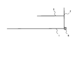
- FIG. 1 is a front view of a glass antenna provided on a rear glass of an automobile, showing an antenna pattern of a first embodiment of the present invention.
- the glass antenna of the first embodiment includes a power supply unit 6, a first element 1 extending from the power supply unit 6 in a substantially horizontal direction (leftward), and a second element extending from the power supply unit 6 in a substantially vertical direction (upward). 2 and a first auxiliary element 3 extending upward from the first element 1.
- the first auxiliary element 3 is disposed separately from the second element 2 and extends in the same direction (for example, substantially parallel) as the extending direction of the second element 2.
- the length of each element of the glass antenna of the first embodiment is adjusted to a length suitable for receiving the UHF band digital terrestrial television broadcasting band.
- the length of the first element 1 is 220 mm
- the second The length of the element 2 is 75 mm
- the sensitivity over the entire band of the reception frequency can be adjusted by the first element 1, and the sensitivity on the low frequency side can be adjusted by the second element 2, and a flat characteristic can be obtained in the entire band.
- the antenna sensitivity can be improved overall in the reception band. That is, impedance matching over the entire band of the reception frequency is difficult only with the two elements 1 and 2 extending from the power supply unit, so that the impedance in a wide frequency band becomes close to a desired value by the first auxiliary element 3. Antenna sensitivity can be improved.
- the antenna sensitivity in the entire band of the reception frequency can be improved.
- FIG. 2 is a front view of a glass antenna provided on a rear glass of an automobile, showing an antenna pattern according to a second embodiment of the present invention.
- the extending direction of the first auxiliary element 3 is different from that of the first embodiment.
- the glass antenna of the second embodiment has a power feeding unit 6, a first element 1, a second element 2, and a first auxiliary element 3.
- the first auxiliary element 3 of the second embodiment is disposed separately from the second element 2 and extends in a direction opposite to the extending direction of the second element 2 (for example, substantially parallel).
- FIG. 3 is a front view of a glass antenna provided on a rear glass of an automobile, showing an antenna pattern according to a third embodiment of the present invention.
- the arrangement of the first auxiliary element 3 is different from that of the first embodiment.
- the glass antenna of the third embodiment has a power feeding unit 6, a first element 1, a second element 2, and a first auxiliary element 3.
- the first auxiliary element 3 of the third embodiment is arranged separately from the first element 1 and extends from the second element 2 in the same direction (for example, substantially parallel) as the extending direction of the first element 1.
- flat characteristics can be obtained in the entire band. Note that the antenna of the first embodiment can obtain higher sensitivity.
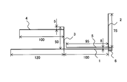
- FIG. 4 is a front view of a glass antenna provided on a rear glass of an automobile, showing an antenna pattern according to a fourth embodiment of the present invention.
- the glass antenna of the fourth embodiment is different from the first embodiment in that it has a second auxiliary element 4 and a third auxiliary element 5.
- the glass antenna of the fourth embodiment includes a power feeding unit 6, a first element 1, a second element 2, a first auxiliary element 3, a second auxiliary element 4, and a third auxiliary element 5.
- the first auxiliary element 3 of the fourth embodiment is spaced apart from the second element 2 and extends in the same direction (for example, substantially parallel) as the extending direction of the second element 2.
- the second auxiliary element 4 is connected to the first auxiliary element 3, is spaced apart from the first element 1, and extends in the same direction (for example, substantially parallel) as the extending direction of the first element 1.
- the second auxiliary element 4 has a length of 100 mm and is connected to a position 5 mm from the tip of the first auxiliary element 3.
- the second auxiliary element 4 may be connected in the middle of the first auxiliary element 3 or may be connected to the tip portion.
- the third auxiliary element 5 is connected to the power feeding unit 6 and extends along the first element 1 (for example, substantially parallel).
- the third auxiliary element 5 may be extended from the second element 2 without extending from the power feeding unit 6.
- the third auxiliary element 5 has a length of 95 mm and is arranged in parallel with the first element 1 at an interval of 8 mm.
- the third auxiliary element 5 should be long as long as the tip does not contact the first auxiliary element 3. For this reason, if the 1st auxiliary element 3 and the 2nd element 2 are arrange
- both the second auxiliary element 4 and the third auxiliary element 5 are provided, but a glass antenna having one of the second auxiliary element 4 or the third auxiliary element 5 is also included in the scope of the present invention. It is.
- the frequency at which high sensitivity is obtained in the reception band can be adjusted by the second auxiliary element 4 connected to the middle or the tip of the first auxiliary element 3.
- the second auxiliary element 4 connected to the middle or the tip of the first auxiliary element 3.
- the sensitivity of the reception band can be further improved by the third auxiliary element 5.
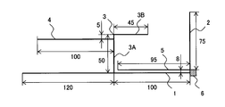
- FIG. 5 is a front view of a glass antenna provided on a rear glass of an automobile, showing an antenna pattern according to a fifth embodiment of the present invention.
- the glass antenna of the fifth embodiment is different from the fourth embodiment in that a bent portion 3B is formed at the tip of the first auxiliary element 3.
- the glass antenna of the fifth embodiment includes a power feeding unit 6, a first element 1, a second element 2, a first auxiliary element 3, a second auxiliary element 4, and a third auxiliary element 5.
- the first auxiliary element 3 of the fifth embodiment is disposed separately from the second element 2, and has a main body 3A extending in the same direction (for example, substantially parallel) as the extending direction of the second element 2, and a main body 3A.
- a bent portion 3B that is bent at a substantially right angle from the tip of the first portion and extends rightward toward the second element 2.
- the bent portion 3B is disposed separately from the first element 1 and extends in a direction opposite to the extending direction of the first element 1 (for example, substantially parallel).
- the main body 3A has a length of 50 mm, and the bent portion 3B has a length of 45 mm. Further, the bent portion 3B may be connected to the distal end portion of the first auxiliary element 3 or may be connected in the middle.
- the location where the second auxiliary element 4 is connected to the first auxiliary element 3 and the location where the bent portion 3B is connected to the main body portion 3A are preferably different positions. That is, the second auxiliary element 4 and the bent portion 3B may be connected to the main body portion 3A of the first auxiliary element 3 so as to be stepped.
- the second auxiliary elements 4 may be connected so as to be different from each other.
- the antenna can be arranged in a narrow region.
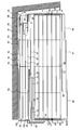
- FIG. 6 is a front view of a glass antenna provided on a rear glass 81 of an automobile, showing an antenna pattern according to a sixth embodiment of the present invention.
- an antenna having a configuration similar to that of the glass antenna of the fifth embodiment is mounted as the fourth antenna 70. Furthermore, the first antenna 10, the second antenna 50, the third antenna 60, and the It is composed of five antennas 100.
- the fourth antenna 70 of the sixth embodiment is different from the glass antenna of the fifth embodiment in that a plurality of second auxiliary elements 4 are provided and a bent portion 2B is formed at the tip of the second element 2.
- the fourth antenna 70 of the sixth embodiment includes a power feeding unit 6, a first element 1, a second element 2, a first auxiliary element 3, a second auxiliary element 4, and a third auxiliary element 5.
- the second element 2 of the sixth embodiment includes a main body portion 2A extending in a substantially vertical direction (upward) from the power supply portion 6, and a bent portion 2B bending rightward from the tip of the main body portion 2A and extending rightward.
- the bent portion 2B is disposed apart from the first element 1 and extends in the same direction (for example, substantially parallel) as the extending direction of the first element 1.
- the main body 2A has a length of 75 mm, and the bent portion 2B has a length of 30 mm.
- the total length of the second element 2 is approximately ⁇ / 3.
- the bent portion 2B may be connected to the tip portion of the second element 2 or may be connected in the middle.
- the length of the second element may be considered as the length from the power feeding part 6 to the tip of the bent part 2B.
- the two second auxiliary elements 4 of the sixth embodiment are arranged in parallel with being spaced apart from the first element 1, connected to the first auxiliary element 3, and in the same direction as the extending direction of the first element 1 (for example, Stretched substantially parallel).
- Each second auxiliary element 4 has a length of 100 mm, and the upper second auxiliary element 4 is connected to a position 5 mm from the tip of the main body 3A of the first auxiliary element 3, and the two second auxiliary elements 4 are 5 mm in length.
- Two second auxiliary elements 4 may be connected in the middle of the first auxiliary element 3, or one may be connected to the tip.
- the fourth antenna 70 of the sixth embodiment may use the glass antenna of any of the above-described embodiments in addition to the illustrated configuration.
- the antenna 70 of the sixth embodiment since a plurality of the second auxiliary elements 4 are provided, higher sensitivity can be obtained in the reception band.
- the bent portion 2B is formed at the tip of the second element 2, the antenna can be arranged in a narrow region without shortening the element length.
- the first antenna 10 includes a first power feeding unit 15, a horizontal first element 11, a horizontal second element, a vertical element 31, and auxiliary elements 12 and 13.
- the horizontal first element 11 is connected to the first power feeding unit 15 and extends in a substantially horizontal direction (left direction in the figure).
- the horizontal second element is connected to the first power feeding unit 15 and extends substantially in parallel with the horizontal first element 11 in the same direction as the horizontal first element 11 (right direction in the drawing).
- the horizontal second element is folded downward from the main body portion 21 extending from the first power feeding portion 15 and at the end of the main body portion 21, is substantially parallel along the main body portion 21, and approaches the first power feeding portion 15. And a folded portion 22 extending in the direction.
- the vertical element 31 extends from the first power feeding unit 15 in a direction different from the extending direction of the horizontal first element 11 and the extending direction of the horizontal second element.
- the auxiliary element 12 extends downward from the intersection between the vertical portion and the horizontal portion of the first element, and is then disposed substantially in parallel along the horizontal first element 11. Further, the auxiliary element 12 is arranged close to the defogger 90 (for example, 5 mm apart in parallel) so as to be capacitively coupled to the uppermost heating filament 91 of the defogger 90.
- the auxiliary element 13 extends rightward from the vertical portion of the first element, and is arranged substantially in parallel along the horizontal first element 11.
- the length of each element of the first antenna 10 is adjusted so that the FM radio broadcast band and the DAB band 3 are suitably received.
- the second antenna 50 includes a plurality of horizontal filaments 52, a plurality of vertical filaments 53 connecting the horizontal filaments 52, a second feeding unit 54 provided at an end of the horizontal filaments 52, and folded portions 56 and 57.
- One of the horizontal filaments 52 is disposed between the auxiliary element 13 of the first antenna 10 and the folded portion 22.
- the folded portions 56 and 57 extend upward from the uppermost horizontal filament 52, are folded laterally, and extend close to the horizontal filament 52 (for example, 5 mm apart in parallel).
- the folded portions 56 and 57 are arranged close to the body flange 82 of the vehicle body (for example, 5 mm apart and in parallel), and the second antenna 50 and the body flange 82 (that is, ground) are capacitively coupled.
- each filament is arranged in an area suitable for receiving the AM radio broadcast band (526.5 to 1606.5 kHz).
- the third antenna 60 is constituted by the filaments of the defogger 90, and the defogger 90 functions as the third antenna.
- the defogger 90 functioning as the third antenna 60 includes a pair of bus bars 93 provided on the left and right sides of the rear glass 81, a plurality of heating wires 91 (horizontal wires) connecting the two bus bars 93, and a plurality of heating wires. It has a vertical line 92 connecting the lines 91.
- the number of vertical filaments 92 may be one or more.
- the bus bar 93 is provided with a defogger coil 94 and a third power feeding unit 95. That is, one bus bar 93 is connected to the power source via the defogger coil 94, and the other bus bar 93 is connected to the ground via the defogger coil 94.
- the defogger coil 94 suppresses noise in the reception frequency band that flows into the third antenna 60 from the power source and the ground.
- the defogger coil 94 and the third power supply unit 95 are arranged at the center of the bus bar 93 with the defogger coil 94 on the upper side and the third power supply unit 95 on the lower side, but the positions where the defogger coil 94 and the third power supply unit 95 are arranged. Can be anywhere on the bus bar 93. Furthermore, the order (upper and lower positional relationship) in which the defogger coil 94 and the third power feeding unit 95 are arranged is not limited to that illustrated.
- a diversity antenna may be configured by the first antenna 10 and the third antenna 60, and at least one of the FM radio broadcast wave and the DAB band 3 broadcast wave may be diversity-received.
- the third antenna 60 defogger 90
- the power supply unit 95 is provided in the bus bar 93 far from the first antenna 10 (for example, on the right side). Good.
- the first antenna 10 and the fourth antenna 70 may constitute a diversity antenna and receive TV broadcast waves with diversity.
- the third antenna 60 has parallel auxiliary filaments 96, 97, 98 extending from the bus bar 93 and a fourth auxiliary element 89.
- the ends of the parallel auxiliary filaments 96, 97, and 98 are at positions separated from each other. Further, a part of the parallel auxiliary line 96 and a part of the parallel auxiliary line 97 are arranged in close proximity to each other so as to be along each other. Furthermore, a part of the parallel auxiliary line 97 and a part of the parallel auxiliary line 98 are arranged in close proximity to each other so as to be along each other. In this manner, since the two parallel auxiliary filaments 96, 97, and 98 are arranged so as to overlap, each parallel auxiliary filament is capacitively coupled at the end. In addition, it may be arrange
- the fourth auxiliary element 89 extends upward from the bus bar 93 on the right side (close to the fourth antenna 70), and bends and extends in the left direction. Note that the fourth auxiliary element 89 may extend from the outermost horizontal filament 91.
- the fifth antenna 100 has a fifth power feeding portion 101, a plurality of vertical wires, and one horizontal wire.
- Each of the power feeding units 15, 54, 95, 101 is connected to a reception amplifier by a connection line (for example, an AV electric wire), and the reception amplifier is connected to a receiver by a high frequency cable (for example, a coaxial cable).
- the receiving amplifier is connected to the ground (vehicle body).
- the following is an explanation of antenna sensitivity when the arrangement or length of elements described below is changed, and the configuration of other elements is not changed.
- the antenna sensitivity is a value obtained by measuring the antenna sensitivity in all directions (360 degrees) in the horizontal plane and calculating the average.
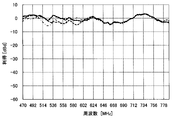
- FIG. 7 shows the gain (sensitivity) of the fourth antenna 70 with respect to a vertically polarized signal in the terrestrial digital TV broadcasting band depending on the presence or absence of the first auxiliary element 3 in the antenna of the sixth embodiment.
- the fourth antenna 70 used for the measurement differs from the configuration shown in FIG. 6 in that the first auxiliary element 3 does not have the bent portion 3B (only the main body portion 3A) and has the second auxiliary element 4. No.
- the lengths of the other elements are the same as described above.
- the characteristic when the first auxiliary element 3 is provided is indicated by a solid line
- the characteristic when the first auxiliary element 3 is not provided is indicated by a broken line.
- the first auxiliary element 3 is a straight line with a length of 95 mm, and the length and arrangement of the other elements are as shown in FIG. According to FIG. 7, in the case where the first auxiliary element 3 is provided, the drop in gain on the low frequency side is small, and the average gain in the band is high.
- FIG. 8 shows a vertical polarization signal in the digital terrestrial TV broadcast band when the length of the main body 3A is changed when the bent portion 3B is provided in the first auxiliary element 3 in the antenna of the sixth embodiment.
- the gain (sensitivity) of the fourth antenna 70 is shown.
- the 4th antenna 70 used for the measurement does not have the 2nd auxiliary element 4 unlike the structure shown in FIG.
- the lengths of the other elements are the same as described above (for example, the length of the bent portion 3B is 45 mm).
- the characteristic when the length of the main body 3A is 50 mm is indicated by a solid line
- the characteristic when it is 60 mm is indicated by a dotted line
- the characteristic when 70 mm is indicated by a broken line
- the characteristic when it is 40 mm Is shown by a one-dot chain line.
- the drop in gain on the low frequency side is small and the average gain in the band is the highest.
- FIG. 9 shows the gain (sensitivity) of the fourth antenna 70 with respect to a vertically polarized signal in the terrestrial digital TV broadcast band when the position where the second auxiliary element 4 is connected to the main body 3A in the antenna of the sixth embodiment is changed. ). That is, FIG. 9 shows that the second auxiliary element 4 is connected to the main body portion 3A of the first auxiliary element 3 having the bent portion 3B or connected to the bending point (the connection point between the main body portion 3A and the bent portion 3B). It shows the difference in characteristics depending on whether or not.
- FIG. 9 shows the gain (sensitivity) of the fourth antenna 70 with respect to a vertically polarized signal in the terrestrial digital TV broadcast band when the position where the second auxiliary element 4 is connected to the main body 3A in the antenna of the sixth embodiment is changed. ). That is, FIG. 9 shows that the second auxiliary element 4 is connected to the main body portion 3A of the first auxiliary element 3 having the bent portion 3B or connected to the bending point (the connection point between the main body portion 3A and
- the characteristics when the upper second auxiliary element 4 is connected to a position 5 mm from the tip of the main body 3A (a position different from the connection position of the bent portion 3B) are indicated by solid lines, and the upper second auxiliary element is shown.
- the characteristic when 4 is connected to the tip of the main body 3A (the same position as the connection position of the bent portion 3B) is indicated by a dotted line.
- two second auxiliary elements 4 were provided, and the distance between them was 5 mm.
- the drop in gain on the middle band side is small and the average gain in the band is high.
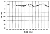
- FIG. 10 shows the gain (sensitivity) of the fourth antenna 70 with respect to a vertically polarized signal in the terrestrial digital TV broadcast band with and without the fourth auxiliary element 89 in the antenna of the sixth embodiment.
- the characteristic when the fourth auxiliary element 89 is provided is indicated by a solid line, and the characteristic when the fourth auxiliary element 89 is not provided is indicated by a broken line.
- the drop in gain on the high frequency side is small, and the average gain in the band is high.
Landscapes
- Details Of Aerials (AREA)
- Support Of Aerials (AREA)
Abstract
車両用窓ガラスに配置されるガラスアンテナであって、給電部と、前記給電部から所定の方向に延伸する第1エレメントと、前記第1エレメントと第1の所定の角度において、前記給電部から延伸する第2エレメントと、前記第1エレメント又は前記第2エレメントに第2の所定の角度で接続され、他方のエレメントから離れて配置される第1補助エレメントと、を備える。
Description
本発明は、ガラス板の表面に配置されるガラスアンテナ関し、特に、広帯域で平坦な特性を得るアンテナに関する。
UHF帯では広い帯域で放送が行われており、例えば、地上デジタルTV放送では470~770MHzの300MHzの帯域を使用している。これは、中心周波数(620MHz)の約±25%(150MHz)の帯域が必要である。
一方、UHF帯の広い帯域の全域にわたり高い感度を得るガラスアンテナの設計は難しい。
この問題を解決するアンテナとして、特許文献1は受信利得と指向特性を改善したUHF帯の受信アンテナを開示する。特許文献1に開示されるアンテナは、所望の周波数帯に長さをあわせた水平線条と垂直線条とをそれぞれ共通の給電点から延伸させたアンテナであり、水平偏波及び垂直偏波の両方を受信できるため、指向特性を改善することができる。さらに、複数本の水平線条及び垂直線条とを設けることで、共振周波数が広がり、広い帯域にわたって受信感度を高めることができる。
しかし、特許文献1に記載されたアンテナでは、複数本の水平線条及び垂直線条を接続する場合、隣接する水平線条同士や隣接する垂直線条同士が近接すると、線条が太くなったと同程度に受信帯域が広がる効果しか得られなかった。
本発明は、UHF帯の広い帯域内の全域で高い感度が得られるガラスアンテナを提供することを目的とする。
すなわち、本発明は、車両用窓ガラスに配置されるガラスアンテナであって、給電部と、前記給電部から所定の方向に延伸する第1エレメントと、前記第1エレメントと第1の所定の角度において、前記給電部から延伸する第2エレメントと、前記第1エレメント又は前記第2エレメントに第2の所定の角度で接続され、他方のエレメントから離れて配置される第1補助エレメントと、を備えることを特徴とするガラスアンテナである。
また、本発明は、さらに、前記第1補助エレメントは、前記他方のエレメントと30mm以上離れて略平行に配置されることを特徴とするガラスアンテナである。
また、本発明は、さらに、前記第1補助エレメントは、前記他方のエレメントと100mm以上離れて略平行に配置されることを特徴とするガラスアンテナである。
また、本発明は、さらに、前記第1エレメントは、略水平方向に延伸するエレメントであり、前記第1補助エレメントは、前記第1エレメントに接続され、垂直方向に延伸することを特徴とするガラスアンテナである。
また、本発明は、さらに、前記第1補助エレメントの途中又は先端に接続される少なくとも一つの第2補助エレメントを備えることを特徴とするガラスアンテナである。
また、本発明は、さらに、前記第2補助エレメントは二つ設けられており、一つの前記第2補助エレメントは、前記第1補助エレメントの途中に接続され、他の前記第2補助エレメントは、前記第1補助エレメントの先端に接続されることを特徴とするガラスアンテナである。
また、本発明は、さらに、前記他方のエレメント又は前記給電部に接続される少なくとも一つの第3補助エレメントを備えることを特徴とするガラスアンテナである。
また、本発明は、さらに、前記第1補助エレメントは、前記第1エレメントに接続されており、前記第3補助エレメントは、前記第2エレメント又は前記給電部に接続されており、前記第1補助エレメントに近づくように延伸することを特徴とするガラスアンテナである。
また、本発明は、さらに、前記ガラスアンテナは、中心周波数の波長をλとする周波数帯を受信するためのアンテナであり、前記窓ガラスの波長短縮率をαとして、水平方向に延伸する前記第1エレメントの長さは略2αλ/3であり、垂直方向に延伸する前記第2エレメントの長さは略αλ/3であることを特徴とするガラスアンテナである。
また、本発明は、さらに、前記第1エレメントの先端部及び前記第2エレメントの先端部の少なくとも一方を折り曲げたことを特徴とするガラスアンテナである。
また、本発明は、さらに、前記窓ガラスには、1対のバスバと前記一対のバスバの間に複数の加熱線条が設けられたデフォッガが配置されることを特徴とするガラスアンテナである。
また、本発明は、さらに、前記デフォッガの加熱線条によって第2アンテナが構成され、前記第2アンテナの給電部は、前記第1エレメントが接続される給電部から遠いバスバに設けられることを特徴とするガラスアンテナである。
また、本発明は、さらに、前記デフォッガのバスバから延伸する第4補助エレメントを備え、前記第4補助エレメントは、前記第1エレメント、前記第2エレメント又は前記第1補助エレメントに近接し、容量結合することを特徴とするガラスアンテナである。
本発明の代表的な実施形態によれば、広帯域で平坦な特性を得ることができる。
図1から図6は、本発明の実施形態のガラスアンテナを車内側から見た図である。
図1に示すように、本発明の実施形態のガラスアンテナは、自動車のリヤガラスに設けられ、給電部6と、給電部6から延伸する第1エレメント1と、給電部6から第1エレメント1と異なる方向に延伸する第2エレメント2と、第1エレメント1から延伸する第1補助エレメント3とを有する。第1補助エレメント3は、好ましくは、その先端が第2エレメント2と離隔して配置され、第2エレメント2と同一方向に延伸する。なお、第1補助エレメント3と第2エレメント2との離隔は、両エレメントが独立したエレメントとして機能できる距離だけ離れて配置されることを意味する。具体的には、両エレメントを、30mm以上離して、ほとんど容量結合しない距離で配置することが望ましい。
第1エレメント1と第2エレメント2とは、望ましくは、略直交するように延伸する。より具体的には、第1エレメント1は、水平偏波の電波を受信するために、給電部6から略水平方向に延伸し、第2エレメント2は、垂直偏波の電波を受信するために、給電部6から略垂直方向に延伸するとよい。
給電部6は、接続線(例えば、AV電線)85によって受信アンプ86に接続され、受信アンプ86は高周波ケーブル(例えば、同軸ケーブル)によって受信機に接続される。また、受信アンプ86はアース(車体)に接続される。
また、図2に示すように、第1補助エレメント3は、その先端が第2エレメント2と離隔して配置され、第2エレメント2の延伸方向と反対方向に延伸してもよい。
また、図3に示すように、第1補助エレメント3は、その先端が第1エレメント1と離隔して配置され、第2エレメント2に接続され、第1エレメント1の延伸方向と同一方向に延伸してもよい。
また、図4、図5、図6に示すように、第1補助エレメント3から延伸する第2補助エレメント4を有してもよい。第2補助エレメント4は、好ましくは、その先端が第1エレメント1と離隔して配置され、第1エレメント1の延伸方向と同一方向に延伸する。第2補助エレメント4は、第1補助エレメント3の途中に接続されても、先端部に接続されてもよい。
さらに、図4、図5、図6に示すように、第1エレメント1に沿って延伸する第3補助エレメント5を有してもよい。第3補助エレメント5は、給電部6から延伸しても、第2エレメント2から延伸してもよい。
また、図5、図6に示すように、第1補助エレメント3の先端部を折り曲げた折曲部3Bを形成してもよい。なお、折曲部3Bは、右方向に延伸した第2補助エレメント4として把握することもできる。
また、図6に示すように、第2エレメント2の先端部を折り曲げた折曲部2Bを形成してもよい。なお、図示は省略するが、第1エレメント1の先端部を(例えば、上方向に)折り曲げた折曲部を形成してもよい。
さらに、図6に示すように、複数の第2補助エレメント4を設けてもよい。複数の第2補助エレメント4は、互いに沿って延伸する。この場合、一本の第2補助エレメント4は第1補助エレメント3の途中に接続され、他の第2補助エレメント4は第1補助エレメント3の先端に接続してもよい。
さらに、図6に示すように、本実施形態のアンテナは、デフォッガ90が設けられるリヤガラス81に配置されてもよい。
さらに、図6に示すように、デフォッガ90のバスバ93から延伸し、第1エレメント1に近接して容量結合する第4補助エレメント89を設けてもよい。さらに、第4補助エレメント89が、第1エレメント1、前記第2エレメント2、第1補助エレメント3、第2補助エレメント4、第3補助エレメント5のいずれに近接して配置され、容量結合してもよい。
本発明の実施形態のアンテナは、そのパターンを窓ガラス板の室内面側の所定位置に、導電性のセラミックペーストによって各線条の幅を約0.7mmで印刷し、乾燥後、加熱炉によって焼付けして形成される。また、光を透過する樹脂フィルム上に形成された導電性のパターンによってアンテナを形成して、ガラス板に貼り付けてもよい。
以上に、本発明の実施形態について、自動車のリヤガラス81にアンテナを設ける形態を説明したが、本発明の実施形態のアンテナは、他の箇所(例えば、フロントガラス、サイドガラス)に設けてもよい。
本発明の実施形態のアンテナの各エレメントの長さは、各実施例で後述するように、UHF帯の地上デジタルTV放送波(470~770MHz)を受信するために好適な長さに調整される。なお、UHF帯と同様にVHF帯を受信するために好適なアンテナとすることもできる。
次に、本発明の実施形態のガラスアンテナの作用について説明する。
本実施形態のアンテナは、給電部6から所定の方向(例えば、水平方向)に延伸する第1エレメント1と、第1エレメント1と第1の所定の角度において(例えば、直角に)、給電部6から(例えば、垂直方向に)延伸する第2エレメント2と、第1エレメント1に第2の所定の角度(例えば、直角)で接続され、第2エレメント2から離れて配置される第1補助エレメント3と、を備えるので、広帯域で平坦な特性を得ることができる。
特に、水平方向に延伸する第1エレメント1の長さを略2αλ/3とし、垂直方向に延伸する第2エレメント2の長さを略αλ/3としたので(中心周波数の波長=λ、ガラスの波長短縮率=α)、第1エレメント1によって受信周波数の全帯域にわたる感度を調整し、第2エレメント2によって垂直偏波に対する低域側の感度を調整することができ、全帯域で平坦な特性を得ることができる。
また、第1エレメント1及び第2エレメント2から離れた位置に、第1補助エレメント3を設けることによって、複数の平行なエレメントを設け、これによって、受信帯域で全体的にアンテナ感度を向上することができる。
また、第1補助エレメント3と第2エレメント2とが30mm以上離れて略平行に配置されるので、両エレメント間の容量結合が弱くなり、第1補助エレメント3と第2エレメント2とが相互に独立したエレメントとして機能することができる。このため、両エレメントを30mm程度離れ配置すれば、第1補助エレメント3の長さや配置を調整することによって、高域側の感度を調整することができる。
また、第1補助エレメント3と第2エレメント2とが100mm以上離れて略平行に配置されるので、第3補助エレメント5を取り付ける領域を確保することができる。
また、第1エレメント1は、略水平方向に延伸するエレメントであり、第1補助エレメント3が第1エレメント1に接続され、垂直方向に延伸するので、垂直偏波の信号に対して高い感度を得ることができる。
また、第1補助エレメント3の途中又は先端に接続される少なくとも一つの第2補助エレメント4を備えるので、受信帯域において高感度が得られる周波数を調整することができる。
また、一本の第2補助エレメント4を第1補助エレメント3の途中に接続し、他の第2補助エレメント4を第1補助エレメント3の先端に接続することによって、受信帯域の感度をより向上することができる。
また、第2エレメント2又は給電部6に接続される少なくとも一つの第3補助エレメントを備えるので、受信帯域の高域側における感度を向上することができる。
また、第3補助エレメント5は、第1補助エレメントに近づくように延伸するので、受信帯域の感度をより向上することができる。
また、第1エレメント1の先端部及び第2エレメント2の先端部の少なくとも一方を折り曲げて折曲部を設けたので、エレメント長を短くすることなく、狭い領域にもアンテナを配置することができる。
また、本実施例のアンテナとデフォッガ90とを窓ガラスに配置しても、UHFの受信帯域において高い感度を得ることができる。
また、デフォッガ90の加熱線条91によって第3アンテナ60を構成する。すなわち、デフォッガ90にアンテナ用の給電部95を設けて、デフォッガ90をアンテナとして用いることによって、ダイバーシティアンテナを構成する。UHF帯域の信号をダイバーシティ受信することによって、感度を向上し、指向性を改善することができる。
また、第3アンテナ60の第3給電部95は、第1エレメント1が接続される給電部6から遠いバスバ93に設けるので、ダイバーシティ効果を高めることができる。
また、デフォッガ90のバスバ93から延伸し、第1エレメント1に近接し容量結合する第4補助エレメント89を備えるので、受信帯域の高域側の感度を調整することができる。また、第3アンテナ60の感度も向上することができる。
以下、本発明の種々の実施例について説明する。
<実施例1>
図1は、本発明の第1実施例のアンテナパターンを示し、自動車のリヤガラスに設けるガラスアンテナの正面図である。
図1は、本発明の第1実施例のアンテナパターンを示し、自動車のリヤガラスに設けるガラスアンテナの正面図である。
第1実施例のガラスアンテナは、給電部6と、給電部6から略水平方向(左方)に延伸する第1エレメント1と、給電部6から略垂直方向(上方)に延伸する第2エレメント2と、第1エレメント1から上方に延伸する第1補助エレメント3とを有する。第1補助エレメント3は、第2エレメント2と離隔して配置され、第2エレメント2の延伸方向と同一方向(例えば、略平行)に延伸する。
第1実施例のガラスアンテナの各エレメントの長さは、UHF帯の地上デジタルテレビ放送帯域を受信するために好適な長さに調整されており、第1エレメント1の長さが220mm、第2エレメント2の長さが75mm、第1補助エレメント3の長さが50mmである。すなわち、リヤガラス81の波長短縮率αが0.7であり、地上デジタルテレビ放送帯域の中心周波数(波長=λ)を620MHzとすると、第1エレメント1の長さは略2αλ/3となる。
第1実施例では、第1エレメント1によって受信周波数の全帯域にわたる感度を調整し、第2エレメント2によって低域側の感度を調整することができ、全帯域で平坦な特性を得ることができる。
また、第1補助エレメント3を、第1エレメント1及び第2エレメント2から離れた位置に設けることによって、複数の平行なエレメントを離隔して設ける。これによって、受信帯域で全体的にアンテナ感度を向上することができる。すなわち、給電部から延伸する2本のエレメント1、2だけでは、受信周波数の全帯域にわたるインピーダンスマッチングが難しいことから、第1補助エレメント3によって、広い周波数帯域におけるインピーダンスが所望の値に近くなり、アンテナ感度を向上させることができる。
また、第2エレメント2が受信周波数の低域側でのアンテナ感度の調整に寄与し、第1補助エレメント3が高域側のアンテナ感度の調整に寄与するため、受信周波数の全帯域におけるアンテナ感度を向上することができる。
<実施例2>
図2は、本発明の第2実施例のアンテナパターンを示し、自動車のリヤガラスに設けるガラスアンテナの正面図である。
図2は、本発明の第2実施例のアンテナパターンを示し、自動車のリヤガラスに設けるガラスアンテナの正面図である。
第2実施例のガラスアンテナでは、第1補助エレメント3の延伸方向が、第1実施例と異なる。
第2実施例のガラスアンテナは、給電部6と、第1エレメント1と、第2エレメント2と、第1補助エレメント3とを有する。第2実施例の第1補助エレメント3は、第2エレメント2と離隔して配置され、第2エレメント2の延伸方向と反対方向(例えば、略平行)に延伸する。
第2実施例の前述以外の構成は、第1実施例と同じであるため、同じ符号を付し、それらの説明は省略する。
第2実施例では、前述した第1実施例と同様に、全帯域で平坦な特性を得ることができる。なお、第1実施例のアンテナの方が設置面積を小さくすることができる。
<実施例3>
図3は、本発明の第3実施例のアンテナパターンを示し、自動車のリヤガラスに設けるガラスアンテナの正面図である。
図3は、本発明の第3実施例のアンテナパターンを示し、自動車のリヤガラスに設けるガラスアンテナの正面図である。
第3実施例のガラスアンテナでは、第1補助エレメント3の配置が、第1実施例と異なる。
第3実施例のガラスアンテナは、給電部6と、第1エレメント1と、第2エレメント2と、第1補助エレメント3とを有する。第3実施例の第1補助エレメント3は、第1エレメント1と離隔して配置され、第1エレメント1の延伸方向と同一方向(例えば、略平行)に、第2エレメント2から延伸する。
第3実施例の前述以外の構成は、第1実施例と同じであるため、同じ符号を付し、それらの説明は省略する。
第3実施例では、前述した第1実施例と同様に、全帯域で平坦な特性を得ることができる。なお、第1実施例のアンテナの方が高感度を得ることができる。
<実施例4>
図4は、本発明の第4実施例のアンテナパターンを示し、自動車のリヤガラスに設けるガラスアンテナの正面図である。
図4は、本発明の第4実施例のアンテナパターンを示し、自動車のリヤガラスに設けるガラスアンテナの正面図である。
第4実施例のガラスアンテナは、第2補助エレメント4及び第3補助エレメント5を有する点が第1実施例と異なる。
第4実施例のガラスアンテナは、給電部6と、第1エレメント1と、第2エレメント2と、第1補助エレメント3と、第2補助エレメント4と、第3補助エレメント5とを有する。第4実施例の第1補助エレメント3は、第2エレメント2と離隔して配置され、第2エレメント2の延伸方向と同一方向(例えば、略平行)に延伸する。
第2補助エレメント4は、第1補助エレメント3に接続し、第1エレメント1と離隔して配置され、第1エレメント1の延伸方向と同一方向(例えば、略平行)に延伸する。第2補助エレメント4の長さは100mmで、第1補助エレメント3の先端から5mmの位置に接続される。第2補助エレメント4は、第1補助エレメント3の途中に接続されても、先端部に接続されてもよい。
第3補助エレメント5は、給電部6に接続し、第1エレメント1に沿って(例えば、略平行)に延伸する。なお、第3補助エレメント5は、給電部6から延伸せず、第2エレメント2から延伸してもよい。第3補助エレメント5の長さは95mmで、第1エレメント1と8mmの間隔で平行に配置される。なお、第3補助エレメント5は、その先端が第1補助エレメント3に接触しなければ、長い方がよい。このため、第1補助エレメント3と第2エレメント2とを100mm以上離して配置すると、第3補助エレメント5を長くすることができる。
第4実施例の前述以外の構成は、第1実施例と同じであるため、同じ符号を付し、それらの説明は省略する。
なお、第4実施例において、第2補助エレメント4及び第3補助エレメント5の両方を設けたが、第2補助エレメント4又は第3補助エレメント5の一方を有するガラスアンテナも本発明の範疇に含まれる。
第4実施例では、第1補助エレメント3の途中又は先端に接続される第2補助エレメント4によって、受信帯域において高感度が得られる周波数を調整することができる。特に、第2補助エレメント4を第1補助エレメント3の途中に接続することによって、全帯域における感度を向上させつつ、特定の帯域における感度を容易に調整することができる。また、第3補助エレメント5によって、受信帯域の感度をより向上することができる。
<実施例5>
図5は、本発明の第5実施例のアンテナパターンを示し、自動車のリヤガラスに設けるガラスアンテナの正面図である。
図5は、本発明の第5実施例のアンテナパターンを示し、自動車のリヤガラスに設けるガラスアンテナの正面図である。
第5実施例のガラスアンテナは、第1補助エレメント3の先端に折曲部3Bを形成した点が第4実施例と異なる。
第5実施例のガラスアンテナは、給電部6と、第1エレメント1と、第2エレメント2と、第1補助エレメント3と、第2補助エレメント4と、第3補助エレメント5とを有する。第5実施例の第1補助エレメント3は、第2エレメント2と離隔して配置され、第2エレメント2の延伸方向と同一方向(例えば、略平行)に延伸する本体部3Aと、本体部3Aの先端から略直角に屈曲して第2エレメント2に向かって右方向に延伸する折曲部3Bを有する。折曲部3Bは、第1エレメント1と離隔して配置され、第1エレメント1の延伸方向と反対方向(例えば、略平行)に延伸する。本体部3Aの長さは50mmであり、折曲部3Bの長さは45mmである。また、折曲部3Bは、第1補助エレメント3の先端部に接続されても、途中に接続されてもよい。
なお、第1補助エレメント3において、第2補助エレメント4が第1補助エレメント3に接続される箇所と、折曲部3Bが本体部3Aに接続される箇所とは、異なる位置であるとよい。すなわち、第2補助エレメント4と折曲部3Bは、第1補助エレメント3の本体部3Aに対して段違いになるように接続するとよい。
また、前述したように、折曲部3Bを右方向に延伸した第2補助エレメント4として把握した場合、第2補助エレメント4同士は、互いに段違いになるように接続するとよい。
第5実施例の前述以外の構成は、第4実施例と同じであるため、同じ符号を付し、それらの説明は省略する。
第5実施例では、第1補助エレメント3の先端部を折り曲げて折曲部3Bを設けたので、狭い領域にもアンテナを配置することができる。
<実施例6>
図6は、本発明の第6実施例のアンテナパターンを示し、自動車のリヤガラス81に設けるガラスアンテナの正面図である。
図6は、本発明の第6実施例のアンテナパターンを示し、自動車のリヤガラス81に設けるガラスアンテナの正面図である。
第6実施例のガラスアンテナは、第5実施例のガラスアンテナと類似した構成のアンテナが、第4アンテナ70として実装され、さらに、第1アンテナ10、第2アンテナ50、第3アンテナ60及び第5アンテナ100によって構成される。第6実施例の第4アンテナ70は、第2補助エレメント4を複数設け、第2エレメント2の先端に折曲部2Bを形成した点が第5実施例のガラスアンテナと異なる。
第6実施例の第4アンテナ70は、給電部6と、第1エレメント1と、第2エレメント2と、第1補助エレメント3と、第2補助エレメント4と、第3補助エレメント5とを有する。第6実施例の第2エレメント2は、給電部6から略垂直方向(上方)に延伸する本体部2Aと、本体部2Aの先端から略直角に屈曲して右方に延伸する折曲部2Bを有する。折曲部2Bは、第1エレメント1と離隔して配置され、第1エレメント1の延伸方向と同一方向(例えば、略平行)に延伸する。本体部2Aの長さは75mmであり、折曲部2Bの長さは30mmである。リヤガラス81の波長短縮率αが0.7であり、地上デジタルテレビ放送帯域の中心周波数(波長=λ)を620MHzとすると、第2エレメント2の合計の長さは略αλ/3となる。また、折曲部2Bは、第2エレメント2の先端部に接続されても、途中に接続されてもよい。折曲部2Bが第2エレメント2の途中に接続される場合、第2エレメントの長さは給電部6から折曲部2Bの先端までの長さと考えるとよい。
第6実施例の2本の第2補助エレメント4は、第1エレメント1と離隔して平行に配置され、第1補助エレメント3に接続し、第1エレメント1の延伸方向と同一方向(例えば、略平行)に延伸する。各第2補助エレメント4の長さは100mmで、上側の第2補助エレメント4は第1補助エレメント3の本体部3Aの先端から5mmの位置に接続され、2本の第2補助エレメント4は5mmの間隔で平行に配置される。第2補助エレメント4は、2本が第1補助エレメント3の途中に接続されても、1本が先端部に接続されてもよい。
第6実施例の第4アンテナ70の前述以外の構成は、第5実施例のガラスアンテナと同じであるため、同じ符号を付し、それらの説明は省略する。
なお、第6実施例の第4アンテナ70は、図示した構成の他、前述したいずれの実施例のガラスアンテナを用いてもよい。
第6実施例の第4アンテナ70では、第2補助エレメント4を複数設けたので、受信帯域においてより高い感度を得ることができる。また、第2エレメント2の先端に折曲部2Bを形成したので、エレメント長を短くすることなく、狭い領域にもアンテナを配置することができる。
次に、第6実施例のガラスアンテナにおける第4アンテナ70以外の構成について説明する。
第1アンテナ10は、第1給電部15と、水平第1エレメント11と、水平第2エレメントと、垂直エレメント31と、補助エレメント12、13とを有する。
水平第1エレメント11は、第1給電部15に接続され、略水平方向(図において左方向)に延伸する。前記水平第2エレメントは、第1給電部15に接続され、水平第1エレメント11の延伸方向と同一方向で(図において右方向)、水平第1エレメント11に沿って略平行に延伸する。前記水平第2エレメントは、第1給電部15から延伸する本体部21と、本体部21の端部において下方向に折り返され、本体部21に沿って略平行でかつ第1給電部15に近づく方向に延伸する折り返し部22とによって構成される。
垂直エレメント31は、水平第1エレメント11の延伸方向及び水平第2エレメントの延伸方向と異なる方向に第1給電部15から延伸する。補助エレメント12は、第1エレメントの垂直部と水平部との交点から下方に延伸した後、水平第1エレメント11に沿って略平行に配置される。また、補助エレメント12は、デフォッガ90の最上部の加熱線条91と容量結合するように、デフォッガ90に沿って近接して(例えば、5mm離隔して平行に)配置される。補助エレメント13は、第1エレメントの垂直部から右方に延伸して、水平第1エレメント11に沿って略平行に配置される。
第1アンテナ10の各エレメントの長さは、FMラジオ放送帯域及びDABのバンド3を好適に受信するように調整される。
第2アンテナ50は、複数の水平線条52と、水平線条52を接続する複数の垂直線条53と、水平線条52の端部に設けられる第2給電部54と、折り返し部56、57とを有する。水平線条52の一つは、第1アンテナ10の補助エレメント13と折り返し部22との間に配置される。折り返し部56、57は、最上部の水平線条52から上方向に延伸し、横方向に折り返され、水平線条52に沿って近接して(例えば、5mm離隔して平行に)延伸する。折り返し部56、57は、車体のボディフランジ82に近接して(例えば、5mm離隔して平行に)配置され、第2アンテナ50とボディフランジ82(すなわち、アース)とが容量結合する。第2アンテナ50は、AMラジオ放送帯域(526.5~1606.5kHz)を受信するために好適な面積に、各線条が配置される。
第3アンテナ60はデフォッガ90の線条によって構成され、デフォッガ90が第3アンテナとして機能する。
第3アンテナ60として機能するデフォッガ90は、リヤガラス81の左右に設けられた一対のバスバ93と、二つのバスバ93の間を接続する複数の加熱線条91(水平線条)と、複数の加熱線条91間を接続する垂直線条92とを有する。垂直線条92の数は1本でも複数でもよい。
バスバ93には、デフォッガコイル94及び第3給電部95が設けられる。すなわち、一方のバスバ93はデフォッガコイル94を介して電源に接続し、他方のバスバ93はデフォッガコイル94を介してアースに接続する。デフォッガコイル94によって、電源及びアースから第3アンテナ60に流入する受信周波数帯のノイズを抑制する。
デフォッガコイル94及び第3給電部95は、バスバ93の中央部に、デフォッガコイル94を上側、第3給電部95を下側に配置したが、デフォッガコイル94及び第3給電部95を配置する位置はバスバ93上であればどこでもよい。さらに、デフォッガコイル94及び第3給電部95を配置する順序(上下の位置関係)も、図示したものに限らない。
第1アンテナ10と第3アンテナ60とによってダイバーシティアンテナを構成し、FMラジオ放送波及びDABのバンド3の放送波の少なくとも一つをダイバーシティ受信してもよい。この場合、第3アンテナ60(デフォッガ90)がFMラジオ放送波及びDABのバンド3の放送波を受信する場合、第1アンテナ10から遠い(例えば、右側の)バスバ93に給電部95を設けるとよい。
また、第1アンテナ10と第4アンテナ70とによってダイバーシティアンテナを構成し、TV放送波をダイバーシティ受信してもよい。
また、第3アンテナ60は、バスバ93から延伸する平行補助線条96、97、98と、第4補助エレメント89とを有する。
各平行補助線条96、97、98の端部は、互いに離れた位置にある。また、平行補助線条96の一部と平行補助線条97の一部とは、互いに沿うように略平行に近接して配置される。さらに、平行補助線条97の一部と平行補助線条98の一部とは、互いに沿うように略平行に近接して配置される。このように、各平行補助線条96、97、98の2本をオーバーラップするように配置するので、各平行補助線条が端部で容量結合する。なお、平行補助線条の一部でなく、ほぼ全部が互いに沿うように近接して配置されてもよい。
第4補助エレメント89は、右側の(第4アンテナ70に近い)バスバ93から上方に延伸し、左方向に屈曲して延伸する。なお、第4補助エレメント89は、最外側の水平線条91から延伸してもよい。
第5アンテナ100は、第5給電部101、複数の垂直線条及び1本の水平線条を有する。
各給電部15、54、95、101は、接続線(例えば、AV電線)によって受信アンプと接続され、受信アンプは高周波ケーブル(例えば、同軸ケーブル)によって受信機に接続される。受信アンプはアース(車体)に接続される。
第6実施例では、第1アンテナ10と第4アンテナ70とでダイバーシティ受信をするので、到来波を受信しやすくなり、受信性能を向上することができる。
<アンテナの特性>
次に、本実施例のアンテナの特性について説明する。
次に、本実施例のアンテナの特性について説明する。
以下(図7~図10)は、以下に説明するエレメントの配置又は長さを変えた場合のアンテナ感度の説明であり、他のエレメントの構成は変えていない。また、アンテナ感度は、水平面内の全方向(360度)のアンテナ感度を測定し、その平均を計算した値である。
図7は、第6実施例のアンテナにおいて第1補助エレメント3の有無による地上デジタルTV放送帯域における垂直偏波の信号に対する第4アンテナ70の利得(感度)を示す。なお、測定に使用した第4アンテナ70は、図6に示す構成と異なり、第1補助エレメント3が折曲部3Bを有さず(本体部3Aのみを有する)、第2補助エレメント4を有さない。また、他のエレメントの長さは前述したもので一定とした。図7では、第1補助エレメント3を設けた場合の特性を実線で示し、設けない場合の特性を破線で示す。なお、第1補助エレメント3は直線で、その長さは95mmとし、他のエレメントの長さ及び配置は図4に示したとおりである。図7によると、第1補助エレメント3を設けた場合が、低域側での利得の落ち込みが小さく、かつ帯域内の平均利得が高かった。
図8は、第6実施例のアンテナにおいて第1補助エレメント3に折曲部3Bを設けた場合、本体部3Aの長さを変化させたときの地上デジタルTV放送帯域における垂直偏波の信号に対する第4アンテナ70の利得(感度)を示す。なお、測定に使用した第4アンテナ70は、図6に示す構成と異なり、第2補助エレメント4を有さない。また、他のエレメントの長さは前述したもので一定とした(例えば、折曲部3Bの長さは45mmである。)。図8では、本体部3Aの長さを50mmとした場合の特性を実線で示し、60mmとした場合の特性を点線で示し、70mmとした場合の特性を破線で示し、40mmとした場合の特性を一点鎖線で示す。図8によると、本体部3Aの長さを50~60mmとした場合が、低域側での利得の落ち込みが小さく、かつ帯域内の平均利得が最も高かった。
また、図7の実線と図8の実線とを比較することによって、第1補助エレメント3の折曲部3Bの有無による地上デジタルTV放送帯域における特性の変化を知ることができる。これによると、折曲部3Bを設けた場合(図8)が、受信帯域における平均感度はほとんど変らないが、低域側の感度が向上し、受信周波数の全域にわたって感度が平坦化した。
図9は、第6実施例のアンテナにおいて第2補助エレメント4を本体部3Aへ接続する位置を変化させたときの地上デジタルTV放送帯域における垂直偏波の信号に対する第4アンテナ70の利得(感度)を示す。すなわち、図9は、第2補助エレメント4を、折曲部3Bを有する第1補助エレメント3の本体部3Aに接続するか、屈曲点(本体部3Aと折曲部3Bの接続点)に接続するかによる特性の違いを示す。図9では、上側の第2補助エレメント4を本体部3Aの先端から5mmの位置(折曲部3Bの接続位置と異なる位置)に接続した場合の特性を実線で示し、上側の第2補助エレメント4を本体部3Aの先端(折曲部3Bの接続位置と同じ位置)に接続した場合の特性を点線で示す。いずれの場合も、2本の第2補助エレメント4を設け、その間隔は5mmとした。図9によると、上側の第2補助エレメント4を本体部3Aの先端から5mmの位置に接続した場合が、中域側での利得の落ち込みが小さく、かつ帯域内の平均利得が高かった。
図10は、第6実施例のアンテナにおいて第4補助エレメント89の有無による地上デジタルTV放送帯域における垂直偏波の信号に対する第4アンテナ70の利得(感度)を示す。図10では、第4補助エレメント89を設けた場合の特性を実線で示し、設けない場合の特性を破線で示す。図10によると、第4補助エレメント89を設けた場合が、高域側での利得の落ち込みが小さく、かつ帯域内の平均利得が高かった。
なお、図7~図10を用いて、垂直偏波の信号に対するアンテナ感度を説明したが、同様に、水平偏波に対しても良好なアンテナ感度が得られた。
以上、本発明を添付の図面を参照して詳細に説明したが、本発明はこのような具体的構成に限定されるものではなく、添付した請求の範囲の趣旨内における様々な変更及び同等の構成を含むものである。
本願は2014年2月7日に日本国特許庁に出願された特願2014-22422に基づく優先権を主張し、この出願の全ての内容は参照により本明細書に組み込まれる。
Claims (13)
- 車両用窓ガラスに配置されるガラスアンテナであって、
給電部と、
前記給電部から所定の方向に延伸する第1エレメントと、
前記第1エレメントと第1の所定の角度において、前記給電部から延伸する第2エレメントと、
前記第1エレメント又は前記第2エレメントに第2の所定の角度で接続され、他方のエレメントから離れて配置される第1補助エレメントと、を備えることを特徴とするガラスアンテナ。 - 前記第1補助エレメントは、前記他方のエレメントと30mm以上離れて略平行に配置されることを特徴とする請求項1に記載のガラスアンテナ。
- 前記第1補助エレメントは、前記他方のエレメントと100mm以上離れて略平行に配置されることを特徴とする請求項1に記載のガラスアンテナ。
- 前記第1エレメントは、略水平方向に延伸するエレメントであり、
前記第1補助エレメントは、前記第1エレメントに接続され、垂直方向に延伸することを特徴とする請求項1に記載のガラスアンテナ。 - 前記第1補助エレメントの途中又は先端に接続される少なくとも一つの第2補助エレメントを備えることを特徴とする請求項1に記載のガラスアンテナ。
- 前記第2補助エレメントは二つ設けられており、
一つの前記第2補助エレメントは、前記第1補助エレメントの途中に接続され、
他の前記第2補助エレメントは、前記第1補助エレメントの先端に接続されることを特徴とする請求項5に記載のガラスアンテナ。 - 前記他方のエレメント又は前記給電部に接続される少なくとも一つの第3補助エレメントを備えることを特徴とする請求項1に記載のガラスアンテナ。
- 前記第1補助エレメントは、前記第1エレメントに接続されており、
前記第3補助エレメントは、前記第2エレメント又は前記給電部に接続されており、前記第1補助エレメントに近づくように延伸することを特徴とする請求項7に記載のガラスアンテナ。 - 前記ガラスアンテナは、
中心周波数の波長をλとする周波数帯を受信するためのアンテナであり、
前記窓ガラスの波長短縮率をαとして、水平方向に延伸する前記第1エレメントの長さは略2αλ/3であり、垂直方向に延伸する前記第2エレメントの長さは略αλ/3であることを特徴とする請求項1に記載のガラスアンテナ。 - 前記第1エレメントの先端部及び前記第2エレメントの先端部の少なくとも一方を折り曲げたことを特徴とする請求項1に記載のガラスアンテナ。
- 前記窓ガラスには、1対のバスバと前記一対のバスバの間に複数の加熱線条が設けられたデフォッガが配置されることを特徴とする請求項1に記載のガラスアンテナ。
- 前記デフォッガの加熱線条によって第2アンテナが構成され、
前記第2アンテナの給電部は、前記第1エレメントが接続される給電部から遠いバスバに設けられることを特徴とする請求項11に記載のガラスアンテナ。 - 前記デフォッガのバスバから延伸する第4補助エレメントを備え、
前記第4補助エレメントは、前記第1エレメント、前記第2エレメント又は前記第1補助エレメントに近接し、容量結合することを特徴とする請求項11に記載のガラスアンテナ。
Applications Claiming Priority (2)
| Application Number | Priority Date | Filing Date | Title |
|---|---|---|---|
| JP2014022422A JP6379504B2 (ja) | 2014-02-07 | 2014-02-07 | ガラスアンテナ |
| JP2014-022422 | 2014-02-07 |
Publications (1)
| Publication Number | Publication Date |
|---|---|
| WO2015118754A1 true WO2015118754A1 (ja) | 2015-08-13 |
Family
ID=53777571
Family Applications (1)
| Application Number | Title | Priority Date | Filing Date |
|---|---|---|---|
| PCT/JP2014/081371 Ceased WO2015118754A1 (ja) | 2014-02-07 | 2014-11-27 | ガラスアンテナ |
Country Status (2)
| Country | Link |
|---|---|
| JP (1) | JP6379504B2 (ja) |
| WO (1) | WO2015118754A1 (ja) |
Families Citing this family (1)
| Publication number | Priority date | Publication date | Assignee | Title |
|---|---|---|---|---|
| CN115732891A (zh) * | 2022-11-09 | 2023-03-03 | 福耀玻璃工业集团股份有限公司 | 玻璃天线与车辆 |
Citations (4)
| Publication number | Priority date | Publication date | Assignee | Title |
|---|---|---|---|---|
| JP2002100914A (ja) * | 2000-09-26 | 2002-04-05 | Asahi Glass Co Ltd | 自動車用ガラスアンテナ |
| JP2010010962A (ja) * | 2008-06-25 | 2010-01-14 | Asahi Glass Co Ltd | 車両用ガラスアンテナ及び車両用窓ガラス板 |
| JP2010273310A (ja) * | 2009-04-20 | 2010-12-02 | Central Glass Co Ltd | ガラスアンテナ |
| JP2011147102A (ja) * | 2009-12-15 | 2011-07-28 | Central Glass Co Ltd | ガラスアンテナ |
Family Cites Families (1)
| Publication number | Priority date | Publication date | Assignee | Title |
|---|---|---|---|---|
| JP2012248981A (ja) * | 2011-05-26 | 2012-12-13 | Central Glass Co Ltd | 車両用ガラスアンテナ |
-
2014
- 2014-02-07 JP JP2014022422A patent/JP6379504B2/ja not_active Expired - Fee Related
- 2014-11-27 WO PCT/JP2014/081371 patent/WO2015118754A1/ja not_active Ceased
Patent Citations (4)
| Publication number | Priority date | Publication date | Assignee | Title |
|---|---|---|---|---|
| JP2002100914A (ja) * | 2000-09-26 | 2002-04-05 | Asahi Glass Co Ltd | 自動車用ガラスアンテナ |
| JP2010010962A (ja) * | 2008-06-25 | 2010-01-14 | Asahi Glass Co Ltd | 車両用ガラスアンテナ及び車両用窓ガラス板 |
| JP2010273310A (ja) * | 2009-04-20 | 2010-12-02 | Central Glass Co Ltd | ガラスアンテナ |
| JP2011147102A (ja) * | 2009-12-15 | 2011-07-28 | Central Glass Co Ltd | ガラスアンテナ |
Also Published As
| Publication number | Publication date |
|---|---|
| JP6379504B2 (ja) | 2018-08-29 |
| JP2015149665A (ja) | 2015-08-20 |
Similar Documents
| Publication | Publication Date | Title |
|---|---|---|
| JP6221773B2 (ja) | ガラスアンテナ | |
| JP6221779B2 (ja) | ガラスアンテナ | |
| JP5428847B2 (ja) | 自動車用のガラスアンテナ | |
| JP2013131889A (ja) | 車両用ガラスアンテナ | |
| JP6094334B2 (ja) | 車両用ガラスアンテナ | |
| US10541463B2 (en) | Glass antenna | |
| CN103026549A (zh) | 车辆用天线 | |
| JP2005026905A (ja) | 車両用ガラスアンテナ | |
| JP5141500B2 (ja) | 車両用ガラスアンテナ及び車両用窓ガラス | |
| JP2019016867A (ja) | 車両用窓ガラス | |
| US9093751B2 (en) | Glass antenna for vehicle and window glass for vehicle | |
| CN101924267B (zh) | 车辆用玻璃天线及车辆用窗玻璃 | |
| JP6251476B2 (ja) | 車両用ガラスアンテナ | |
| WO2012070303A1 (ja) | アンテナ | |
| WO2012020605A1 (ja) | 車両用アンテナ | |
| JP5470866B2 (ja) | 車両用のガラスアンテナ | |
| JP5742509B2 (ja) | 車両用ガラスアンテナ | |
| JP6926721B2 (ja) | ガラスアンテナ及び車両用窓ガラス | |
| JP6379504B2 (ja) | ガラスアンテナ | |
| JP5434590B2 (ja) | 自動車用ガラスアンテナ及び自動車用窓ガラス板 | |
| JP6985598B2 (ja) | アンテナ及び窓ガラス | |
| JP2015056688A (ja) | ガラスアンテナ | |
| JP2016072910A (ja) | アンテナ及び窓ガラス | |
| JP6481377B2 (ja) | ガラスアンテナ及び窓ガラス | |
| JP5262537B2 (ja) | 車両用のガラスアンテナ |
Legal Events
| Date | Code | Title | Description |
|---|---|---|---|
| 121 | Ep: the epo has been informed by wipo that ep was designated in this application |
Ref document number: 14881959 Country of ref document: EP Kind code of ref document: A1 |
|
| NENP | Non-entry into the national phase |
Ref country code: DE |
|
| 122 | Ep: pct application non-entry in european phase |
Ref document number: 14881959 Country of ref document: EP Kind code of ref document: A1 |