WO2015115641A1 - 集電体の接続構造及び該接続構造を備えた蓄電器 - Google Patents
集電体の接続構造及び該接続構造を備えた蓄電器 Download PDFInfo
- Publication number
- WO2015115641A1 WO2015115641A1 PCT/JP2015/052822 JP2015052822W WO2015115641A1 WO 2015115641 A1 WO2015115641 A1 WO 2015115641A1 JP 2015052822 W JP2015052822 W JP 2015052822W WO 2015115641 A1 WO2015115641 A1 WO 2015115641A1
- Authority
- WO
- WIPO (PCT)
- Prior art keywords
- lead
- current collector
- stepped portion
- lid member
- metal
- Prior art date
- Legal status (The legal status is an assumption and is not a legal conclusion. Google has not performed a legal analysis and makes no representation as to the accuracy of the status listed.)
- Ceased
Links
Images


Classifications
-
- H—ELECTRICITY
- H01—ELECTRIC ELEMENTS
- H01G—CAPACITORS; CAPACITORS, RECTIFIERS, DETECTORS, SWITCHING DEVICES, LIGHT-SENSITIVE OR TEMPERATURE-SENSITIVE DEVICES OF THE ELECTROLYTIC TYPE
- H01G11/00—Hybrid capacitors, i.e. capacitors having different positive and negative electrodes; Electric double-layer [EDL] capacitors; Processes for the manufacture thereof or of parts thereof
- H01G11/74—Terminals, e.g. extensions of current collectors
-
- H—ELECTRICITY
- H01—ELECTRIC ELEMENTS
- H01M—PROCESSES OR MEANS, e.g. BATTERIES, FOR THE DIRECT CONVERSION OF CHEMICAL ENERGY INTO ELECTRICAL ENERGY
- H01M50/00—Constructional details or processes of manufacture of the non-active parts of electrochemical cells other than fuel cells, e.g. hybrid cells
- H01M50/50—Current conducting connections for cells or batteries
- H01M50/528—Fixed electrical connections, i.e. not intended for disconnection
-
- H—ELECTRICITY
- H01—ELECTRIC ELEMENTS
- H01M—PROCESSES OR MEANS, e.g. BATTERIES, FOR THE DIRECT CONVERSION OF CHEMICAL ENERGY INTO ELECTRICAL ENERGY
- H01M10/00—Secondary cells; Manufacture thereof
- H01M10/05—Accumulators with non-aqueous electrolyte
- H01M10/052—Li-accumulators
-
- H—ELECTRICITY
- H01—ELECTRIC ELEMENTS
- H01M—PROCESSES OR MEANS, e.g. BATTERIES, FOR THE DIRECT CONVERSION OF CHEMICAL ENERGY INTO ELECTRICAL ENERGY
- H01M50/00—Constructional details or processes of manufacture of the non-active parts of electrochemical cells other than fuel cells, e.g. hybrid cells
- H01M50/10—Primary casings; Jackets or wrappings
- H01M50/147—Lids or covers
- H01M50/148—Lids or covers characterised by their shape
- H01M50/152—Lids or covers characterised by their shape for cells having curved cross-section, e.g. round or elliptic
-
- H—ELECTRICITY
- H01—ELECTRIC ELEMENTS
- H01M—PROCESSES OR MEANS, e.g. BATTERIES, FOR THE DIRECT CONVERSION OF CHEMICAL ENERGY INTO ELECTRICAL ENERGY
- H01M50/00—Constructional details or processes of manufacture of the non-active parts of electrochemical cells other than fuel cells, e.g. hybrid cells
- H01M50/50—Current conducting connections for cells or batteries
- H01M50/531—Electrode connections inside a battery casing
- H01M50/533—Electrode connections inside a battery casing characterised by the shape of the leads or tabs
-
- H—ELECTRICITY
- H01—ELECTRIC ELEMENTS
- H01M—PROCESSES OR MEANS, e.g. BATTERIES, FOR THE DIRECT CONVERSION OF CHEMICAL ENERGY INTO ELECTRICAL ENERGY
- H01M50/00—Constructional details or processes of manufacture of the non-active parts of electrochemical cells other than fuel cells, e.g. hybrid cells
- H01M50/50—Current conducting connections for cells or batteries
- H01M50/531—Electrode connections inside a battery casing
- H01M50/534—Electrode connections inside a battery casing characterised by the material of the leads or tabs
-
- H—ELECTRICITY
- H01—ELECTRIC ELEMENTS
- H01M—PROCESSES OR MEANS, e.g. BATTERIES, FOR THE DIRECT CONVERSION OF CHEMICAL ENERGY INTO ELECTRICAL ENERGY
- H01M50/00—Constructional details or processes of manufacture of the non-active parts of electrochemical cells other than fuel cells, e.g. hybrid cells
- H01M50/50—Current conducting connections for cells or batteries
- H01M50/531—Electrode connections inside a battery casing
- H01M50/536—Electrode connections inside a battery casing characterised by the method of fixing the leads to the electrodes, e.g. by welding
-
- Y—GENERAL TAGGING OF NEW TECHNOLOGICAL DEVELOPMENTS; GENERAL TAGGING OF CROSS-SECTIONAL TECHNOLOGIES SPANNING OVER SEVERAL SECTIONS OF THE IPC; TECHNICAL SUBJECTS COVERED BY FORMER USPC CROSS-REFERENCE ART COLLECTIONS [XRACs] AND DIGESTS
- Y02—TECHNOLOGIES OR APPLICATIONS FOR MITIGATION OR ADAPTATION AGAINST CLIMATE CHANGE
- Y02E—REDUCTION OF GREENHOUSE GAS [GHG] EMISSIONS, RELATED TO ENERGY GENERATION, TRANSMISSION OR DISTRIBUTION
- Y02E60/00—Enabling technologies; Technologies with a potential or indirect contribution to GHG emissions mitigation
- Y02E60/10—Energy storage using batteries
-
- Y—GENERAL TAGGING OF NEW TECHNOLOGICAL DEVELOPMENTS; GENERAL TAGGING OF CROSS-SECTIONAL TECHNOLOGIES SPANNING OVER SEVERAL SECTIONS OF THE IPC; TECHNICAL SUBJECTS COVERED BY FORMER USPC CROSS-REFERENCE ART COLLECTIONS [XRACs] AND DIGESTS
- Y02—TECHNOLOGIES OR APPLICATIONS FOR MITIGATION OR ADAPTATION AGAINST CLIMATE CHANGE
- Y02E—REDUCTION OF GREENHOUSE GAS [GHG] EMISSIONS, RELATED TO ENERGY GENERATION, TRANSMISSION OR DISTRIBUTION
- Y02E60/00—Enabling technologies; Technologies with a potential or indirect contribution to GHG emissions mitigation
- Y02E60/13—Energy storage using capacitors
Definitions
- the present invention relates to a connection structure of current collectors used in a capacitor and a capacitor having the connection structure.
- FIG. 1 of Japanese Patent Application Laid-Open No. 2010-186782 a first lead made of a metal plate having one end fixed to a current collector and the other end positioned on the back side of the lid member, and one end of the lid member
- a connection structure of a current collector of a lithium ion capacitor (capacitor) having a second lead made of a metal plate fixed to the back surface and the other end welded to the other end of the first lead is shown. Yes.
- the length of the second lead fixed to the lid member is increased in order to facilitate the connection work.
- the length of the second lead is increased, there is a problem that the electric resistance value is increased correspondingly and the amount of heat generated in the connection structure is increased.
- the length of the second lead is simply shortened, there arises a problem that poor welding is likely to occur.
- An object of the present invention is to provide a current collector connection structure in which it is easy to find a welding failure even if the length of the second lead fixed to the lid member is shortened, and a capacitor including the connection structure. It is in.
- another object of the present invention is to provide a current collector connection structure that can be easily welded even if the length of the second lead is shortened, and a capacitor having the connection structure. It is in.
- the present invention relates to a current collector connected to a polar plate of one polarity in a group of electrode plates arranged in a metal case body having an opening, and an opening in a state of being electrically insulated from the case body.
- a current collector connection structure that electrically connects a metal lid member that closes the portion is an object of improvement.
- one end is fixed to the current collector, and the other end is fixed to the back surface of the lid member.
- a second lead formed by laminating a plurality of metal plates whose other end is welded to the other end of the first lead.
- the plurality of metal plates constituting the second lead are arranged so as to form a stepped portion whose other end is displaced stepwise.
- a welded portion for welding the other end of the first lead and the second lead is formed so as to leave a stepped portion in the vicinity of the stepped portion.
- the second lead is constituted by a plurality of metal plates as in the present invention, a plurality of parallel current paths are arranged, so that the electrical resistance value of the connection structure can be lowered.
- a stepped portion shifted in a step shape is provided at the other end of the plurality of metal plates constituting the second lead, and the welded portion of the first lead and the second lead is left so that the stepped portion is left in the vicinity of the stepped portion.
- the plurality of metal plates constituting the second lead are arranged so that one end fixed to the lid member also forms a stepped portion that is shifted stepwise, and one end of the second lead and the back surface of the lid member It may be configured such that the welded portion that welds is formed so as to leave the stepped portion in the vicinity of the stepped portion.
- first lead and the current collector may be formed integrally, which provides the advantage that the number of parts is reduced and the number of connection operations is reduced.
- the plurality of metal plates constituting the second lead may have the same length, and may be overlapped so that both end portions thereof coincide with the stacking direction. Since the metal plates having the same shape and the same dimensions may be stacked, the number of parts can be reduced, and the cost of the parts can be reduced.
- a U-shaped or V-shaped bent portion having a stepped portion at the end of the second lead can be formed. This is because the end position of the end of the metal plate located outside the bent portion is shifted in the longitudinal direction of the metal plate from the end position of the end of the metal plate located inside the bent portion by the thickness of the metal plate. Because it will be.
- the stepped portion can be formed simply by bending the end portion of the second lead.
- the first lead is welded to the end portion of the second lead while being in contact with one metal plate located on the innermost side of the bent portion. If it does in this way, a level difference part can be checked reliably.
- connection structure of the present invention can be applied to various capacitors such as lithium ion secondary batteries and lithium ion capacitors.
- it is welded to a metal cylindrical case body having an opening, a wound-type electrode plate group disposed in the case body, and an electrode plate of one polarity in the wound-type electrode plate group.
- a capacitor having a current collector and a current collector connection structure for electrically connecting between the current lid and a metal lid member that closes the opening while being electrically insulated from the case body Structure can be applied.
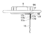
- FIG. 3 is an enlarged front view showing the vicinity of a welded portion between a first lead and a second lead shown in FIG. 1. It is an enlarged front view similar to FIG. 3 of the second embodiment of the present invention.
- FIG. 1 is a front view in which a case main body of a lithium ion capacitor, which is a type of battery to which the current collector connection structure according to the first embodiment of the present invention is applied, is cut away
- FIG. FIG. 3 is a view similar to FIG. 1 showing a state in which the electrode plate group having a lid member is inserted into the case body after the welding process of the lithium ion capacitor shown in FIG. 1, and FIG. It is an enlarged front view which expands and shows the welding part periphery of 1 lead
- a lithium ion capacitor 1 employing the connection structure of the present embodiment includes a bottomed cylindrical case body 3 having an upper end as an opening, and a wound electrode disposed in the case body 3.
- a positive electrode current collector 7 which is welded and electrically connected to a positive electrode plate (not shown) which is an electrode plate of one polarity in the wound electrode plate group 5;
- a metal lid member 9 that closes an opening of the case body 3 while being electrically connected to the electric body 7 and electrically insulated from the case body 3 is provided.
- the case body 3 is made of steel plated with nickel, and a negative electrode current collector 11 welded to and electrically connected to a negative electrode plate (not shown) is welded to the bottom surface. As a result, the case body 3 serves as a negative electrode external terminal of the lithium ion capacitor 1.
- the wound electrode plate group 5 is configured by winding a belt-like positive electrode plate and a negative electrode plate on a shaft core (not shown) via a separator (both not shown).
- the shaft core is made of polypropylene
- the positive electrode plate has a structure in which a positive electrode active material mixture is applied so as to leave uncoated portions on both surfaces of a positive electrode current collector plate made of aluminum foil.
- the uncoated part extends in the longitudinal direction along one edge in the width direction of the positive electrode current collector.
- the negative electrode plate has a structure in which a negative electrode active material is applied so as to leave uncoated portions on both sides of a copper foil current collector plate.
- the uncoated portion extends in the longitudinal direction along one edge in the width direction of the negative electrode current collector.
- the positive electrode plate and the negative electrode plate are interposed via a separator so that the uncoated portion of the positive electrode plate and the uncoated portion of the negative electrode plate are located on both sides of the shaft core. And wind it around the shaft core.
- a positive electrode current collector is welded by laser welding to an uncoated portion of the positive electrode plate exposed at one end side in the longitudinal direction of the wound electrode plate group 5.
- a negative electrode current collector is welded to the uncoated portion of the negative electrode plate exposed at the other end in the longitudinal direction of the wound electrode group 5 by laser welding. Since this welding is well known, a detailed description is omitted.
- the lid member 9 is composed of a first lid component 9A having a terminal portion and a second lid component 9B that is disposed on the back side of the lid member 9 in combination with the first lid component. .
- the lid member 9 is connected to the positive electrode current collector 7 via the first lead 15 and the second lead 17.
- the lid member 9 is caulked to the case main body 3 via a ring-shaped gasket 13 at the upper end opening of the case main body 3, so that the opening of the case main body 3 is electrically insulated from the case main body 3. It is blocking. Thereby, the lid member 9 functions as a positive electrode external terminal.
- the first lead 15 is formed integrally with the positive electrode current collector 7. That is, the first lead 15 in the present embodiment is configured such that a part of the aluminum disc-shaped current collector 7 is cut or raised or provided integrally with the current collector 7. As a result, the number of parts is reduced and the number of connecting operations is also reduced.
- the negative electrode current collector 11 has a protrusion at the center, and this protrusion is connected to the bottom of the case body 3 by resistance welding.
- the second lead 17 is composed of three laminated aluminum plates, and has a width that is substantially the same as that of the first lead 15. As shown in FIG. 3, the stacked three aluminum plates constituting the second lead 17 are stacked so that one end in the longitudinal direction is coincident with the second lead 17, One end is welded to the lid component 9B. After this welding, the three aluminum plates are bent at a substantially right angle at the center in the longitudinal direction and deformed into an L shape. In the state where the lid member 9 is attached to the case body 3 as shown in FIG. 1, the second lead 17 is further bent at an acute angle and deformed into a U shape or a V shape, and the end portion of the first lead 15 is formed. Is to be sandwiched.
- the three aluminum plates 17a, 17b, and 17c constituting the second lead 17 have the same length, and the bent portion 17f is formed by bending, so that as shown in FIGS.
- the positions of the other ends of the aluminum plates 17a, 17b, and 17c are shifted, and the other end of the second lead 17 forms a stepped portion 17d that is shifted stepwise.
- the length of the aluminum plates 17a, 17b, and 17c may be shortened little by little in order so that the stepped portion of the stepped portion 17d becomes clearer.
- the welding of the first lead 15 and the second lead 17 is performed before the case body 3 and the lid member 9 are combined.
- the first lead 15 and the second lead 17 are arranged such that the end portion of the first lead 15 is disposed on the side surface of the second lead 17 opposite to the stepped portion 17d and is adjacent to the stepped portion 17d.
- the pair of welding tools are relatively close to each other.
- the first lead 15 and the second lead 17 are welded by causing ultrasonic vibration to occur in the pair of welding tools.
- the second lead 17 is configured by a plurality of aluminum plates 17a, 17b, and 17c as described above, a plurality of parallel current paths are arranged, and the electrical resistance value of the connection structure can be lowered.
- the length of the second lead 17 is shortened, so that the electrical resistance of the conductive path constituted by the first lead 15 and the second lead 17 is reduced. Can be minimized. Further, since the welding operation is performed in a narrow space between the case main body 3 and the lid member 9, it becomes difficult to accurately weld at the welding location 17e, and poor welding is likely to occur.
- a stepped portion 17d of the aluminum plates 17a, 17b, 17c that is displaced in a stepped manner as a means for easily judging whether or not the welding has been performed satisfactorily.
- a U-shaped or V-shaped bent portion 17f having a stepped portion at the end of the second lead can be formed. This is because the end position of the end portion of the metal plate positioned outside the bent portion 17f is longer than the end position of the end portion of the metal plate positioned inside the bent portion 17f by the thickness of the metal plate. This is because it will shift to. In this way, the stepped portion can be formed simply by bending the end portion of the second lead. By adopting such a configuration, it is only necessary to stack metal plates having the same shape and the same size, so that the types of parts are reduced and the cost of the parts can be reduced.
- the first lead 15 and the second lead 17 are welded in a state where the wound electrode plate group 5 is put in the case body 3. This welding is performed by the wound electrode plate group. Of course, it may be performed before inserting 5 into the case body 3.
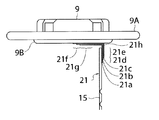
- FIG. 4 is a view similar to FIG. 3 of the second embodiment of the present invention.
- the lid member 9 and the first lead 15 are members having the same functions as the members denoted by the same reference numerals in the first embodiment, and thus description thereof is omitted.
- the three aluminum plates 21a, 21b, and 21c constituting the second lead 21 of the positive electrode current collector 7 are not only the other end to which the first lead 15 is welded, One end welded to the lid member 9 also forms a stepped portion 21f that is shifted stepwise.
- the step portion 21f is formed by providing a difference in the length from the bent portion 21h to one end of the aluminum plates 21a, 21b, and 21c.
- a welded portion 21g designed to weld one end of the second lead 21 and the back surface of the lid member 9 is formed in the vicinity of the stepped portion 21f so as to leave the stepped portion 21f after welding.
- the lithium ion capacitor has been described.
- the present invention is not limited to this, and may be applied to other capacitors, secondary batteries, and their connection structures. is there.
- a wound electrode plate group is used as the electrode plate group, but the present invention is not limited to using a wound electrode plate group as the electrode plate group.
- the length of the first and second leads can be shortened to minimize the electrical resistance, while the occurrence of poor welding is detected at the other end of the first lead. It is possible to easily and clearly confirm that a welding failure has occurred by checking the presence or absence of a step after welding and the number of steps by providing a step portion in which a plurality of metal plates are displaced stepwise. it can.
Landscapes
- Engineering & Computer Science (AREA)
- Power Engineering (AREA)
- Microelectronics & Electronic Packaging (AREA)
- Chemical & Material Sciences (AREA)
- Chemical Kinetics & Catalysis (AREA)
- Electrochemistry (AREA)
- General Chemical & Material Sciences (AREA)
- Connection Of Batteries Or Terminals (AREA)
- Sealing Battery Cases Or Jackets (AREA)
- Electric Double-Layer Capacitors Or The Like (AREA)
Abstract
リチウムイオンキャパシタのような蓄電器に適用可能な、電気抵抗値を最小限に抑えることができ、かつ溶接不良の生じにくい集電体の接続構造を提供する。集電体7を第1のリード15と第2のリード17を介して蓋部材9と接続する。第1のリード15はケース本体3に収納された極板群の集電体7から延び、第2のリード17は蓋部材9の底面に一端が固定された3枚のアルミニウム板よりなる。第2のリード17の端部には、3枚のアルミニウム板の端部がずれた状態で形成される段差部17dを設ける。ケース本体3に蓋部材9を取り付ける前に第1のリード15と第2のリード17とを溶接する。その際に、溶接が予定の位置から外れて施されると、第2のリード17の他端に設けた3枚のアルミニウム板により形成された段差部17dが一部又は全部消失するので、目視でも容易に溶接不良を検知することができる。
Description
本発明は、蓄電器内で使用される集電体の接続構造及び該接続構造を備えた蓄電器に関するものである。
特開2010-186782号公報の図1には、一端が集電体に固定されており且つ他端が蓋部材の裏面側に位置する金属板からなる第1のリードと、一端が蓋部材の裏面に固定されており且つ他端が第1のリードの他端に溶接される金属板からなる第2のリードとを備えたリチウムイオンキャパシタ(蓄電器)の集電体の接続構造が示されている。
特許文献1に示される従来の接続構造では、接続作業を容易にするために、蓋部材に固定される第2のリードの長さを長くしている。しかしながら第2のリードの長さが長くなると、その分電気抵抗値が大きくなり、接続構造において発生する熱量が増加する問題がある。しかしながら単純に第2のリードの長さを短くすると、溶接不良が発生し易くなる問題が発生する。
本発明の目的は、蓋部材に固定される第2のリードの長さを短くしても、溶接不良の発見が容易な集電体の接続構造及び該接続構造を備えた蓄電器を提供することにある。
本発明の他の目的は、上記目的に加えて、第2のリードの長さを短くしても、溶接作業が容易な集電体の接続構造及び該接続構造を備えた蓄電器を提供することにある。
本発明は、開口部を有する金属製のケース本体内に配置された極板群中の一方の極性の極板に接続された集電体と、ケース本体と電気的に絶縁された状態で開口部を塞ぐ金属製の蓋部材との間を電気的に接続する集電体の接続構造を改良の対象とする。本発明の接続構造は、一端が集電体に固定されており且つ他端が蓋部材の裏面側に位置する金属板からなる第1のリードと、一端が蓋部材の裏面に固定されており且つ他端が第1のリードの他端に溶接される複数枚の金属板が積層されてなる第2のリードとを備えている。そして第2のリードを構成する複数枚の金属板は、他端が階段状にずれた段差部を形成するように配置されている。その上で、第1のリードの他端と第2のリードとを溶接する溶接部が、段差部の近傍に段差部を残すように形成されている。本発明のように第2のリードを複数枚の金属板により構成すると、並列電流路が複数配置されることになるため、接続構造の電気抵抗値を下げることができる。また第2のリードを構成する複数枚の金属板の他端に階段状にずれた段差部を設け、段差部の近傍に段差部を残すように第1のリードと第2のリードの溶接部を形成すると、段差部の有無及び段差部の段差の数を確認することにより、簡単に溶接不良が発生しているか否かを確認できる。すなわち溶接後に段差部が確認できない状態が発生していることや、段差部の段差の数が少ないことは、溶接部の溶接金属の量が少ないことを示している。したがって本発明によれば、段差部の有無または段差部の段差の数を確認することにより、容易に溶接不良の発生の有無を確認することができる。
第2のリードを構成する複数枚の金属板は、蓋部材に固定された一端も階段状にずれた段差部を形成するように配置されており、第2のリードの一端と蓋部材の裏面とを溶接する溶接部が、段差部の近傍に段差部を残すように形成されているように構成してもよい。このように構成することにより、第1のリードの他端と第2のリードとの溶接部と同じく、段差部の有無や段差部の段差の数を確認することにより、蓋部材と第2のリードとの溶接不良をも容易に検知することが可能である。
また第1のリードと集電体とは、一体に形成されていてもよく、これにより部品点数が少なくなる上、接続作業数が減るという利点が得られる。
第2のリードを構成する複数枚の金属板は、同じ長さを有していて、それぞれの両端部が積層方向に一致するように重ねられていてもよく、このような構成を採用すると、同一形状及び同一寸法の金属板を重ねればよいため、部品の種類が少なくなって、部品のコストを下げることができる。複数枚の金属板の他端はそれぞれ一緒に曲げられると、第2のリードの端部に段差部を有するU字状またはV字状の曲げ部を形成することができる。これは金属板の厚み分だけ、曲げ部の外側に位置する金属板の端部の終端位置が、曲げ部の内側に位置する金属板の端部の終端位置よりも金属板の長手方向にずれることになるためである。このようにすると、第2のリードの端部に曲げ加工を施すだけで、段差部が形成できる。この場合、第1のリードは、曲げ部の最も内側に位置する1枚の金属板と接触した状態で、第2のリードの端部に溶接するのが好ましい。このようにすると段差部を確実に確認することができる。
本発明の接続構造は、リチウムイオン二次電池、リチウムイオンキャパシタ等の種々の蓄電器に適用することができる。例えば、開口部を有する金属製の円筒型のケース本体と、ケース本体内に配置された捲回型極板群と、捲回型極板群の中の一方の極性の極板に溶接された集電体と、ケース本体と電気的に絶縁された状態で前記開口部を塞ぐ金属製の蓋部材との間を電気的に接続する集電体の接続構造とを有する蓄電器に、前述の接続構造を適用することができる。
以下、図面を参照しながら本発明の集電体の接続構造の実施の形態の一例の構成を詳細に説明する。図1は、本発明の第1の実施の形態に係る集電体の接続構造が適用された蓄電器の一種であるリチウムイオンキャパシタのケース本体を切り欠いて表した正面図であり、図2は図1に示したリチウムイオンキャパシタの、溶接工程の後にケース本体内に蓋部材を備えた極板群を挿入した状態を示す図1と同様の図であり、図3は図1に示した第1のリードと第2のリードとの溶接部周辺を拡大して示す拡大正面図である。
各図に示すように、本実施形態の接続構造を採用したリチウムイオンキャパシタ1は、上端を開口部とする有底円筒型のケース本体3と、ケース本体3内に配置された捲回型極板群5と、捲回型極板群5の中の一方の極性の極板である正極板(図示していない)に溶接されて電気的に接続された正極集電体7と、正極集電体7と電気的に接続され且つケース本体3と電気的に絶縁された状態でケース本体3の開口部を塞ぐ金属製の蓋部材9とを有する。
ケース本体3は、ニッケルメッキが施されたスチール製であり、底面には負極板(図示していない)に溶接されて電気的に接続された負極集電体11が溶接されている。これによりケース本体3はリチウムイオンキャパシタ1の負極外部端子としての役割を果たす。
捲回型極板群5は、図示しない軸芯に、帯状の正極板と負極板とをセパレータ(いずれも図示していない)を介して捲回して構成されている。軸芯はポリプロピレン製であり、正極板はアルミニウム箔製の正極集電板の両面に未塗工部を残すように正極活物質合剤が塗布された構造を有している。未塗工部は、正極集電体の幅方向の一方の縁に沿って長手方向に延びている。また負極板は銅箔の集電板の両面に未塗工部を残すように負極活物質が塗布された構造を有している。未塗工部は、負極集電体の幅方向の一方の縁に沿って長手方向に延びている。捲回型極板群5を形成する際には、正極板の未塗工部と負極板の未塗工部が軸芯の両側に位置するように、正極板と負極板とをセパレータを介して軸芯に捲回する。捲回型極板群5の長手方向の一端側に露出する正極板の未塗工部に正極集電体がレーザ溶接により溶接される。また捲回型極板群5の長手方向の他端側に露出する負極板の未塗工部に負極集電体がレーザ溶接により溶接される。この溶接は周知であるため詳細な説明は省略する。
蓋部材9は、端子部を備えた第1の蓋構成部品9Aと第1の蓋部品と組み合わされて蓋部材9の裏面側に配置される第2の蓋構成部品9Bとから構成されている。蓋部材9は、第1のリード15と第2のリード17とを介して正極集電体7に接続されている。蓋部材9は、ケース本体3の上端開口部にリング状のガスケット13を介してケース本体3にかしめられることにより、ケース本体3とは電気的に絶縁された状態でケース本体3の開口部を塞いでいる。これにより蓋部材9は正極外部端子として機能する。
本実施の形態では、第1のリード15は、正極集電体7と一体に形成されている。すなわち本実施の形態における第1のリード15は、アルミニウム製の円板状の集電体7の一部が切り起こされるか、集電体7と一体に設けられて構成されている。これにより部品点数が少なくなり、接続作業数も減少する。なお負極集電体11は、中央部に突出部を有していて、この突出部がケース本体3の底部に抵抗溶接により接続されている。
第2のリード17は、積層された3枚のアルミニウム板より構成されており、第1のリード15と実質的に同じ寸法の幅を有する。図3に示すように、第2のリード17を構成する積層された3枚のアルミニウム板は、長手方向の一方の端部が一致するように重ねられた状態で、蓋部材9の第2の蓋構成部品9Bに一端が溶接されている。この溶接をした後、3枚のアルミニウム板は、長手方向の中央部においてほぼ直角に曲げられてL字状に変形されている。図1のように蓋部材9がケース本体3に取り付けられた状態では、第2のリード17はさらに鋭角に曲げられてU字状またはV字状に変形され、第1のリード15の端部を挟むようになっている。
第2のリード17を構成する3枚のアルミニウム板17a、17b、17cはそれぞれ長さが同じであり、曲げ加工により曲げ部17fが形成されたことにより、図2及び図3に示すように、アルミニウム板17a、17b、17cの他端の位置がずれた状態になり、第2のリード17の他端が階段状にずれた段差部17dを形成している。なおアルミニウム板17a、17b、17cの長さを順番に少しずつ短くして、段差部17dの段差がより明確になるようにしてもよい。
第1のリード15と第2のリード17との溶接は、ケース本体3と蓋部材9とを組み合わせる前に行われる。第1のリード15と第2のリード17とは、段差部17dとは反対側の第2のリード17の側面に第1のリード15の端部を配置し、段差部17dに隣接する位置において第1のリード15と第2のリード17(アルミニウム板17a、17b、17c)とを両側から挟むように超音波溶接用の一対の溶接工具を配置し、一対の溶接工具を相対的に近付けながら超音波振動を一対の溶接工具に生じさせることにより、第1のリード15と第2のリード17とを溶接する。このように第2のリード17を複数枚のアルミニウム板17a、17b、17cで構成すると、並列電流路が複数配置されることになり、接続構造の電気抵抗値を下げることができる。
また図2によく示されているように、本実施の形態では第2のリード17の長さを短くしたため、第1のリード15と第2のリード17とにより構成される導電路の電気抵抗を最小限に抑えることができる。また溶接作業はケース本体3と蓋部材9との間の狭い空間で行われるために、正確に溶接箇所17eで溶接することが難しくなり、溶接不良が生じやすくなる。
そこで溶接が良好に行われたかどうかを容易に判断する手段として設けたのが、アルミニウム板17a、17b、17cの階段状にずれた段差部17dである。このような段差部17dを、溶接箇所17eに隣接して設けることにより、もしも溶接が溶接箇所17eからケース本体3に近付く方向に外れて行われると、段差部17dが全部又は一部溶けて消失してしまう。従って、溶接後に目視により段差部17dが存在するか、または段差部17dの段差が三段揃っているかを確認し、段差部17dの段差が全て残っていれば溶接が良好に行われ、段差が消えていたり段差の数が足りないときには、溶接不良が生じたことを容易且つ明確に検知することができる。
本実施の形態のように、同一形状の複数枚金属板の両端を一致させて重ね合わせるように第2のリードを形成して、複数枚の金属板を途中部分において、それぞれ一緒に曲げると、第2のリードの端部に段差部を有するU字状またはV字状の曲げ部17fを形成することができる。これは金属板の厚み分だけ、曲げ部17fの外側に位置する金属板の端部の終端位置が、曲げ部17fの内側に位置する金属板の端部の終端位置よりも金属板の長手方向にずれることになるためである。このようにすると、第2のリードの端部に曲げ加工を施すだけで、段差部が形成できる。このような構成を採用すると、同一形状及び同一寸法の金属板を重ねればよいため、部品の種類が少なくなって、部品のコストを下げることができる。
上記実施の形態では、捲回型極板群5をケース本体3に入れた状態で第1のリード15と第2のリード17とを溶接しているが、この溶接は捲回型極板群5をケース本体3内に挿入する前に行ってもよいのは勿論である。
図4は、本発明の第2の実施の形態の図3と同様の図である。蓋部材9及び第1のリード15は、第1の実施の形態において同じ符号を付して示した部材と同一の機能を有する部材なので、説明を省略する。第2の実施の形態においては、正極集電体7の第2のリード21を構成する3枚のアルミニウム板21a、21b、21cは、第1のリード15が溶接される他端のみならず、蓋部材9に溶接される一端も階段状にずれた段差部21fを形成している。この段差部21fは、アルミニウム板21a、21b、21cの曲げ部21hから一端までの長さにもそれぞれ相違を設けることにより形成される。第2のリード21の一端と蓋部材9の裏面とを溶接するように設計されている溶接部21gは、段差部21fの近傍に、溶接後に段差部21fを残すように形成されている。このように構成することにより、第1のリード15の他端と第2のリード21との溶接部21dと同じく、段差部21fの有無や段差部21fの段差の数を確認することにより、蓋部材9と第2のリード21との間の溶接不良も容易に検知することが可能である。
上記各実施の形態では、リチウムイオンキャパシタについて説明をしたが、本発明はこれに限定されるものではなく、他のキャパシタや二次電池及びそれらの接続構造に適用しても良いのは勿論である。
上記実施の形態では、極板群として捲回型極板群を用いているが、本発明は極板群として捲回型極板群を用いる場合に限定されるものではない。
本発明の集電体の接続構造においては、第1及び第2のリードの長さを短くして電気抵抗を最小限に抑えることができる一方、溶接不良の発生を第1のリードの他端に複数の金属板が階段状にずれた段差部を設けることにより、溶接後の段差の有無や、段差の数を確認することにより、溶接不良が生じたことを容易且つ明確に確認することができる。
1 リチウムイオンキャパシタ(蓄電器)
3 ケース本体
5 捲回型極板群
7 集電体
9 蓋
15 第1のリード
17,21 第2のリード
17d 段差部
3 ケース本体
5 捲回型極板群
7 集電体
9 蓋
15 第1のリード
17,21 第2のリード
17d 段差部
Claims (8)
- 開口部を有する金属製のケース本体内に配置された極板群中の一方の極性の極板に接続された集電体と、前記ケース本体と電気的に絶縁された状態で前記開口部を塞ぐ金属製の蓋部材との間を電気的に接続する集電体の接続構造であって、
一端が前記集電体に固定されており且つ他端が前記蓋部材の裏面側に位置する金属板からなる第1のリードと、
一端が前記蓋部材の前記裏面に固定されており且つ他端が前記第1のリードの他端に溶接される複数枚の金属板が積層されてなる第2のリードとを備え、
前記第2のリードを構成する前記複数枚の金属板は、前記他端が階段状にずれた段差部を形成するように配置されており、
前記第1のリードの他端と前記第2のリードとを溶接する溶接部が、前記段差部の近傍に前記段差部を残すように形成されていることを特徴とする集電体の接続構造。 - 前記第2のリードを構成する前記複数枚の金属板は、前記一端が階段状にずれた段差部を形成するように配置されており、
前記第2のリードの前記一端と前記蓋部材の前記裏面とを溶接する溶接部が、前記段差部の近傍に前記段差部を残すように形成されていることを特徴とする請求項1に記載の集電体の接続構造。 - 前記第1のリードと前記集電体とが一体に形成されている請求項1または2に記載の集電体の接続構造。
- 前記複数枚の金属板は、同じ長さを有していて、それぞれの両端部が積層方向に一致するように重ねられており、
前記複数枚の金属板の他端はそれぞれ一緒に曲げられて前記第2のリードの端部に前記段差部を有するU字状またはV字状の曲げ部を形成しており、
前記第1のリードは前記曲げ部の最も内側に位置する1枚の前記金属板と接触した状態または該1枚の金属板と該1枚の金属板に隣接する他の1枚の金属板との間に配置された状態で、前記第2のリードの端部に溶接されている請求項1に記載の集電体の接続構造。 - 前記溶接部は超音波溶接により形成されている請求項1に記載の集電体の接続構造。
- 開口部を有する金属製の円筒型のケース本体と、
前記ケース本体内に配置された捲回型極板群と、
前記捲回型極板群の中の一方の極性の極板に溶接された集電体と、
前記ケース本体と電気的に絶縁された状態で前記開口部を塞ぐ金属製の蓋部材との間を電気的に接続する集電体の接続構造とを有する蓄電器であって、
前記集電体の接続構造は、一端が前記集電体に固定されており且つ他端が前記蓋部材の裏面側に位置する金属板からなる第1のリードと、
一端が前記蓋部材の前記裏面に固定されており且つ他端が前記第1のリードの他端に溶接される複数枚の金属板が積層されてなる第2のリードとを備え、
前記第2のリードを構成する前記複数枚の金属板は、前記他端が階段状にずれた段差部を形成するように配置されており、
前記第1のリードの他端と前記第2のリードとを溶接する溶接部が、前記段差部の近傍に前記段差部を残すように形成されていることを特徴とする蓄電器。 - 前記第1のリードは前記集電体の一部が切り起こされて形成されており、
前記第1のリードの前記他端と対向する前記蓋部材の前記裏面の領域に、前記複数枚の金属板の前記一端が溶接されており、
前記複数枚の金属板は、同じ長さを有していて、それぞれの両端部が積層方向に一致するように重ねられており、
前記複数枚の金属板の他端はそれぞれ一緒に曲げられて前記第2のリードの端部に前記段差部を有するU字状またはV字状の曲げ部を形成しており、
前記第1のリードは前記曲げ部の最も内側に位置する1枚の前記金属板と接触した状態または該1枚の金属板と該1枚の金属板に隣接する他の1枚の金属板との間に配置された状態で、前記第2のリードの端部に溶接されている請求項6に記載の蓄電器。 - 前記溶接部は超音波溶接により形成されている請求項7に記載の蓄電器。
Priority Applications (1)
| Application Number | Priority Date | Filing Date | Title |
|---|---|---|---|
| JP2015560062A JPWO2015115641A1 (ja) | 2014-02-03 | 2015-02-02 | 集電体の接続構造及び該接続構造を備えた蓄電器 |
Applications Claiming Priority (2)
| Application Number | Priority Date | Filing Date | Title |
|---|---|---|---|
| JP2014018715 | 2014-02-03 | ||
| JP2014-018715 | 2014-02-03 |
Publications (1)
| Publication Number | Publication Date |
|---|---|
| WO2015115641A1 true WO2015115641A1 (ja) | 2015-08-06 |
Family
ID=53757206
Family Applications (1)
| Application Number | Title | Priority Date | Filing Date |
|---|---|---|---|
| PCT/JP2015/052822 Ceased WO2015115641A1 (ja) | 2014-02-03 | 2015-02-02 | 集電体の接続構造及び該接続構造を備えた蓄電器 |
Country Status (2)
| Country | Link |
|---|---|
| JP (1) | JPWO2015115641A1 (ja) |
| WO (1) | WO2015115641A1 (ja) |
Cited By (2)
| Publication number | Priority date | Publication date | Assignee | Title |
|---|---|---|---|---|
| CN109509640A (zh) * | 2018-12-27 | 2019-03-22 | 南通瑞泰电子有限公司 | 一种便于安装的铝电解电容器 |
| WO2023133854A1 (zh) * | 2022-01-14 | 2023-07-20 | 宁德时代新能源科技股份有限公司 | 电池单体、电池、用电设备、电池单体的制造方法及设备 |
Citations (4)
| Publication number | Priority date | Publication date | Assignee | Title |
|---|---|---|---|---|
| JP2002298825A (ja) * | 2001-03-29 | 2002-10-11 | Tdk Corp | 電気化学デバイスの製造方法、および電気化学デバイス |
| JP2004152707A (ja) * | 2002-11-01 | 2004-05-27 | Shin Kobe Electric Mach Co Ltd | 二次電池及び該製造方法 |
| JP2010282822A (ja) * | 2009-06-04 | 2010-12-16 | Hitachi Vehicle Energy Ltd | 密閉型電池および密閉型電池の製造方法 |
| JP2011023531A (ja) * | 2009-07-15 | 2011-02-03 | Ud Trucks Corp | 蓄電デバイスおよびその製造方法 |
-
2015
- 2015-02-02 JP JP2015560062A patent/JPWO2015115641A1/ja active Pending
- 2015-02-02 WO PCT/JP2015/052822 patent/WO2015115641A1/ja not_active Ceased
Patent Citations (4)
| Publication number | Priority date | Publication date | Assignee | Title |
|---|---|---|---|---|
| JP2002298825A (ja) * | 2001-03-29 | 2002-10-11 | Tdk Corp | 電気化学デバイスの製造方法、および電気化学デバイス |
| JP2004152707A (ja) * | 2002-11-01 | 2004-05-27 | Shin Kobe Electric Mach Co Ltd | 二次電池及び該製造方法 |
| JP2010282822A (ja) * | 2009-06-04 | 2010-12-16 | Hitachi Vehicle Energy Ltd | 密閉型電池および密閉型電池の製造方法 |
| JP2011023531A (ja) * | 2009-07-15 | 2011-02-03 | Ud Trucks Corp | 蓄電デバイスおよびその製造方法 |
Cited By (2)
| Publication number | Priority date | Publication date | Assignee | Title |
|---|---|---|---|---|
| CN109509640A (zh) * | 2018-12-27 | 2019-03-22 | 南通瑞泰电子有限公司 | 一种便于安装的铝电解电容器 |
| WO2023133854A1 (zh) * | 2022-01-14 | 2023-07-20 | 宁德时代新能源科技股份有限公司 | 电池单体、电池、用电设备、电池单体的制造方法及设备 |
Also Published As
| Publication number | Publication date |
|---|---|
| JPWO2015115641A1 (ja) | 2017-03-23 |
Similar Documents
| Publication | Publication Date | Title |
|---|---|---|
| JP5716398B2 (ja) | 電池及びその製造方法 | |
| KR102568341B1 (ko) | 축전 소자 | |
| US20170365839A1 (en) | Energy storage device | |
| JP5326125B2 (ja) | 非水電解質二次電池 | |
| JP6064879B2 (ja) | 蓄電装置 | |
| JP2018106806A (ja) | バスバー、蓄電モジュール、および、配線モジュール | |
| JP6756266B2 (ja) | 蓄電装置及び蓄電装置の製造方法 | |
| JP5965396B2 (ja) | 電池用負極端子および電池用負極端子の製造方法 | |
| KR20180023634A (ko) | 이차전지의 전극탭 용접 방법 및 그에 따른 전극탭 용접 구조 | |
| JP6079338B2 (ja) | 蓄電装置及び蓄電装置の製造方法 | |
| JP2012054027A (ja) | 角形密閉二次電池 | |
| KR102487890B1 (ko) | 이차 전지 | |
| JP6911654B2 (ja) | 蓄電装置及び蓄電装置の製造方法 | |
| JP6519334B2 (ja) | 蓄電装置の製造方法 | |
| CN111081965A (zh) | 电池和电池的制造方法 | |
| CN108232280B (zh) | 方形二次电池及其制造方法 | |
| WO2021039267A1 (ja) | 角形二次電池及びその製造方法 | |
| JPWO2015115641A1 (ja) | 集電体の接続構造及び該接続構造を備えた蓄電器 | |
| JP7056560B2 (ja) | 蓄電素子及び蓄電素子の製造方法 | |
| US11342618B2 (en) | Secondary battery, method of manufacturing the same, and method of manufacturing conductive member for the same | |
| JP2017091723A (ja) | 蓄電装置の製造方法、及び蓄電装置 | |
| JP7808280B2 (ja) | 蓄電装置、及び蓄電装置の製造方法 | |
| JP6772830B2 (ja) | 蓄電装置 | |
| WO2023054134A1 (ja) | 蓄電装置および蓄電装置の製造方法 | |
| JP2020021728A (ja) | 蓄電装置 |
Legal Events
| Date | Code | Title | Description |
|---|---|---|---|
| 121 | Ep: the epo has been informed by wipo that ep was designated in this application |
Ref document number: 15743718 Country of ref document: EP Kind code of ref document: A1 |
|
| ENP | Entry into the national phase |
Ref document number: 2015560062 Country of ref document: JP Kind code of ref document: A |
|
| NENP | Non-entry into the national phase |
Ref country code: DE |
|
| 122 | Ep: pct application non-entry in european phase |
Ref document number: 15743718 Country of ref document: EP Kind code of ref document: A1 |