WO2015115400A1 - 軸シール装置及び回転機械 - Google Patents
軸シール装置及び回転機械 Download PDFInfo
- Publication number
- WO2015115400A1 WO2015115400A1 PCT/JP2015/052143 JP2015052143W WO2015115400A1 WO 2015115400 A1 WO2015115400 A1 WO 2015115400A1 JP 2015052143 W JP2015052143 W JP 2015052143W WO 2015115400 A1 WO2015115400 A1 WO 2015115400A1
- Authority
- WO
- WIPO (PCT)
- Prior art keywords
- rotor
- thin plate
- pressure side
- shaft seal
- seal device
- Prior art date
Links
Images


Classifications
-
- F—MECHANICAL ENGINEERING; LIGHTING; HEATING; WEAPONS; BLASTING
- F16—ENGINEERING ELEMENTS AND UNITS; GENERAL MEASURES FOR PRODUCING AND MAINTAINING EFFECTIVE FUNCTIONING OF MACHINES OR INSTALLATIONS; THERMAL INSULATION IN GENERAL
- F16J—PISTONS; CYLINDERS; SEALINGS
- F16J15/00—Sealings
- F16J15/16—Sealings between relatively-moving surfaces
- F16J15/32—Sealings between relatively-moving surfaces with elastic sealings, e.g. O-rings
- F16J15/3284—Sealings between relatively-moving surfaces with elastic sealings, e.g. O-rings characterised by their structure; Selection of materials
- F16J15/3288—Filamentary structures, e.g. brush seals
-
- F—MECHANICAL ENGINEERING; LIGHTING; HEATING; WEAPONS; BLASTING
- F16—ENGINEERING ELEMENTS AND UNITS; GENERAL MEASURES FOR PRODUCING AND MAINTAINING EFFECTIVE FUNCTIONING OF MACHINES OR INSTALLATIONS; THERMAL INSULATION IN GENERAL
- F16J—PISTONS; CYLINDERS; SEALINGS
- F16J15/00—Sealings
- F16J15/16—Sealings between relatively-moving surfaces
- F16J15/32—Sealings between relatively-moving surfaces with elastic sealings, e.g. O-rings
- F16J15/3284—Sealings between relatively-moving surfaces with elastic sealings, e.g. O-rings characterised by their structure; Selection of materials
- F16J15/3292—Lamellar structures
-
- F—MECHANICAL ENGINEERING; LIGHTING; HEATING; WEAPONS; BLASTING
- F01—MACHINES OR ENGINES IN GENERAL; ENGINE PLANTS IN GENERAL; STEAM ENGINES
- F01D—NON-POSITIVE DISPLACEMENT MACHINES OR ENGINES, e.g. STEAM TURBINES
- F01D11/00—Preventing or minimising internal leakage of working-fluid, e.g. between stages
- F01D11/001—Preventing or minimising internal leakage of working-fluid, e.g. between stages for sealing space between stator blade and rotor
-
- F—MECHANICAL ENGINEERING; LIGHTING; HEATING; WEAPONS; BLASTING
- F05—INDEXING SCHEMES RELATING TO ENGINES OR PUMPS IN VARIOUS SUBCLASSES OF CLASSES F01-F04
- F05D—INDEXING SCHEME FOR ASPECTS RELATING TO NON-POSITIVE-DISPLACEMENT MACHINES OR ENGINES, GAS-TURBINES OR JET-PROPULSION PLANTS
- F05D2240/00—Components
- F05D2240/55—Seals
- F05D2240/59—Lamellar seals
Definitions
- the present invention relates to a shaft seal device and a rotary machine.
- a shaft seal device is used.
- a non-contact type labyrinth seal has been widely used.
- such a non-contact type labyrinth seal needs to be configured so that the tip of the seal fin does not come into contact even during shaft vibration or thermal transient thermal deformation during the rotational transition period (starting and stopping). there were. For this reason, it was necessary to increase the clearance (seal clearance) at the tip of the seal fin to some extent. On the other hand, if the seal clearance is too large, the working fluid leaks.
- Patent Document 1 discloses a shaft seal device as a technique for reducing such leakage of working fluid.
- This shaft sealing device includes a sealing body in which flat thin plates having a predetermined width dimension in the axial direction of the rotor are arranged in multiple layers along the circumferential direction of the rotor.
- the present invention has been made in view of the above circumstances, and an object thereof is to provide a rotating machine capable of suppressing flutter.
- the shaft seal device includes a housing disposed to face the outer peripheral surface of the rotor that rotates about the axis, and extends radially inward from the housing in the rotor circumferential direction.
- a shaft sealing device comprising a sealing body in which a plurality of thin plates are laminated, a contact portion formed from a region including a radially inner end portion in surface contact with another thin plate in the front-rear direction of the rotor rotation direction, A non-contact portion that is formed from a region outside the contact portion in the radial direction and is not in contact with the other thin plate.
- the movement of the thin plates is constrained when the tips of the thin plates adjacent to each other are in surface contact with each other in the operating state of the rotor.
- the low pressure side plate and the high pressure side plate are provided on the low pressure side and the high pressure side, respectively, with the thin plate interposed therebetween, and the low pressure side plate It is good also as a structure from which the exposure of the thin plate from is larger than a high voltage
- the exposure on the high pressure side of the shaft seal device can be made smaller than that on the low pressure side.
- the thin plate in the shaft seal device according to any one of the above aspects, may be in surface contact with another thin plate in the front-rear direction in the rotational direction in a state where the thin plate is not in contact with the rotor. Good.
- the biasing member is provided between the seal body and the housing and biases the seal body outward in the rotor radial direction. It is good also as a structure which has.
- the rotating machine according to the fifth aspect of the present invention includes the shaft seal device according to any one of the above aspects.
- FIG. 1 is a schematic configuration diagram of a gas turbine 1 according to the present embodiment.
- a gas turbine 1 shown in FIG. 1 includes a compressor 2 that takes in a large amount of air and compresses it, a combustor 3 that mixes and burns fuel into the air compressed by the compressor 2, and a combustor 3.
- the generated combustion gas is introduced into the turbine 4, and the turbine 4 that rotates by converting the thermal energy of the combustion gas into rotation energy and a part of the rotation power of the turbine 4 are transmitted to the compressor 2.
- the turbine 4 generates power by converting the thermal energy of the combustion gas into mechanical rotational energy by blowing the combustion gas onto the rotor blades 7 provided in the rotor 5.
- the turbine 4 is provided with a plurality of stationary blades 6 on the casing 8 side of the turbine 4 in addition to the plurality of rotor blades 7 on the rotor 5 side. These moving blades 7 and stationary blades 6 are alternately arranged in the axial direction of the rotor 5.
- the moving blade 7 receives the pressure of the combustion gas flowing in the axial direction and rotates the rotor 5 around the axis.
- the rotational energy given to the rotor 5 is extracted from the shaft end and used.
- a seal body 10 is provided as a shaft seal for reducing the amount of combustion gas leaking from the high pressure side to the low pressure side.
- the compressor 2 is coaxially connected to the turbine 4 by a rotor 5. Thereby, the compressor 2 compresses outside air using the rotation of the turbine 4 to generate compressed air. This compressed air is supplied to the combustor 3.
- a plurality of moving blades 7 are provided on the rotor 5, and a plurality of stationary blades 6 are provided on the casing 8 side of the compressor 2.
- the rotor blades 7 and the stationary blades 6 are alternately arranged in the axial direction of the rotor 5.
- a seal body 10 is also provided between the stationary blade 6 and the rotor 5. The seal body 10 is provided to reduce the amount of compressed air leaking from the high pressure side to the low pressure side.
- the seal body 10 is not limited to the application to the gas turbine 1.
- it can be widely used for rotating machines that convert energy into work by rotating a shaft and flowing a fluid, such as large fluid machines such as steam turbines, compressors, water turbines, refrigerators, and pumps.
- the seal body 10 can also be used to suppress the flow of fluid in the axial direction of the rotor 5.
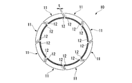
- FIG. 2 is a schematic configuration diagram of the seal body 10 viewed from the axial direction of the rotor 5.
- the seal body 10 has a plurality of arc-shaped (eight in the present embodiment) shaft seal devices 11 arranged in an annular shape along the circumferential direction of the rotor 5.
- a gap t is formed between the circumferential ends 12, 12 of the adjacent shaft seal devices 11 arranged in this way.
- each shaft seal device 11 will be described with reference to FIG.
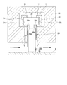
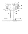
- FIG. 3 is a cross-sectional configuration diagram of the shaft seal device 11 in a cross section including the axis of the rotor 5.
- Each shaft seal device 11 is inserted into the housing 30 (corresponding to the stationary blade 6, the moving blade 7, and the bearing portions 8 a and 9 a) to prevent leakage of working fluid in the annular space between the rotor 5 and the housing 30. Installed.
- the shaft seal device 11 includes a plurality of thin plates 20, holding rings 21 and 22, a high-pressure side plate 23, and a low-pressure side plate 24.
- the thin plate 20 is a metal member that is arranged in a multiple manner at a minute interval along the circumferential direction of the rotor 5.
- the holding rings 21 and 22 are configured to sandwich the thin plate 20 from both sides at the outer peripheral side base end 27 of the thin plate 20.
- the cross section in the circumferential direction of the holding rings 21 and 22 is formed in a substantially C shape.
- the high-pressure side plate 23 is sandwiched between the holding ring 21 and one edge that faces the high-pressure side region of the thin plate 20.
- the low-pressure side plate 24 is sandwiched between the other edge of the thin plate 20 facing the low-pressure side region and the holding ring 22.
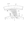
- the thin plate 20 has an inner peripheral side width (axial width of the rotor 5) narrower than the width of the outer peripheral side base end 27 (axial width of the rotor 5). It is comprised by the thin steel plate which made the substantially T-shape by being formed. On both side edges, notches 20a and 20b are formed at positions where the width is narrowed. A plurality of thin plates 20 are stacked along the circumferential direction (rotation direction d) of the rotor 5. Further, the adjacent thin plates 20 are fixedly connected to each other at the outer peripheral side base end 27 by, for example, welding.
- the thin plate 20 has a predetermined rigidity based on the plate thickness in the circumferential direction of the rotor 5. Furthermore, it is fixed to the holding rings 21 and 22 so that an angle formed between the thin plate 20 and the circumferential surface of the rotor 5 with respect to the rotation direction of the rotor 5 is an acute angle.
- the thin plate 20 gradually increases in angle with the circumferential surface of the rotor 5 from the rear side in the rotational direction d of the rotor 5 toward the front side (in an obtuse angle). Arranged).
- a gap g is formed.
- a plurality of adjacent thin plates 20 are in surface contact with each other in the vicinity of the inner peripheral side end portion 26 in the rotation direction d front-rear direction of the rotor 5 to form a contact portion 28.
- the thin plate 20 is in contact with each other to form the contact portion 28 in a region including the radially inner end of the thin plate 20.
- the thin plates 20 are separated from each other to form a non-contact portion 28b.
- the non-contact part 28b refers to a region on the surface of the thin plate 20 in a region separated from each other.
- the thin plate 20 Since the thin plate 20 is formed of a steel plate as described above, it has a certain elastic restoring force (flexibility). In other words, forces that press against each other act on a plurality of adjacent thin plates 20. Therefore, the curved portion 29 is formed on the outer peripheral side of the contact portion 28 by elastic deformation. In the bending portion 29, the thin plate 20 is bent backward in the rotation direction d.
- the high-pressure side plate 23 and the low-pressure side plate 24 are provided with stepped portions 23 a and 24 a so that the outer circumferential side is wide in the axial width of each rotor 5.
- the step portions 23a and 24a are fitted into the notches 20a and 20b of the thin plate 20, respectively.
- the holding ring 21 has a concave groove 21a on a surface facing one side edge (high-pressure side) of the outer peripheral side base ends 27 of the plurality of thin plates 20.
- the holding ring 22 has a concave groove 22 a on the surface facing the other side edge (low pressure side) of the outer peripheral side base ends 27 of the plurality of thin plates 20.
- a holding ring is provided on one side edge (high-pressure side) on the outer peripheral side. 21 concave grooves 21a are fitted. Further, the other side edge (low pressure side) on the outer peripheral side is fitted into the concave groove 22 a of the holding ring 22.
- annular concave groove 31 is formed on the inner peripheral wall surface of the housing 30, and the annular concave groove 31 is wider on the outer peripheral side in the axial direction of the rotor 5 than on the inner peripheral side.
- it is set as the shape by which the level
- the thin plate 20, the holding rings 21 and 22, and the high-pressure side are placed in the groove 31 of the housing 30 so that the surface facing the outer peripheral side of the step contacts the inner peripheral surface of the holding rings 21 and 22.
- the side plate 23 and the low-pressure side plate 24 are fitted.
- the inner peripheral side end portion 26 of the thin plate 20 protrudes more toward the rotor 5 than the high pressure side plate 23.
- the inner peripheral side end portion 26 of the thin plate 20 protrudes to the rotor 5 side from the low pressure side plate 24, but the protruding amount is set smaller than that of the high pressure side. That is, the thin plate 20 is more exposed to the working fluid G on the low pressure side than on the high pressure side.
- the high-pressure side plate 23 shields a wider area on the side surface of the thin plate 20 from the working fluid G.
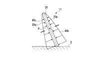
- FIG. 5A when the gas pressure of the working fluid from the high pressure side region to the low pressure side region is applied to each thin plate 20, the thin plate 20 is near the inner peripheral side end portion 26 and on the high pressure side.
- a gas pressure distribution 40a is formed, in which the gas pressure is highest at the corner portion r1, and the gas pressure gradually decreases toward the diagonal corner portion r2.
- the thin plate 20 has a T-shape.
- FIGS. 5A and 5B only the rectangular portion where the bending occurs is shown and the other portions are not shown for the sake of simplicity. ing.
- the surface of the thin plate 20 facing the rotor 5 is a lower surface 20q, and the back side is an upper surface 20p.
- a gas pressure distribution 40a is formed as shown in FIG. 5A.
- the gas pressure is adjusted so that the gas pressure applied to the lower surface 20q is higher than the gas pressure applied to the upper surface 20p at an arbitrary position along the cross section of each thin plate 20.
- the working fluid G flowing from the high pressure side region toward the low pressure side region flows from between the high pressure side plate 23 and the outer peripheral surface of the rotor 5. Thereafter, as shown in FIG. 5A, the working fluid G flows between the outer peripheral surface of the rotor 5 and the inner peripheral side end portion 26 of the thin plate 20, and along the upper surface 20p and the lower surface 20q of each thin plate 20, It flows radially from the portion r1 to the corner r2. As the working fluid G flows in this way, a low pressure region expands toward the outer peripheral side base end 27 of the thin plate 20. Therefore, the gas pressure distributions 40b and 40c applied perpendicularly to the upper surface 20p and the lower surface 20q of each thin plate 20 are as shown in FIG. 5B. More specifically, the gas pressure distributions 40 b and 40 c have a triangular distribution shape that increases as it approaches the inner peripheral side end portion 26 of the thin plate 20 and decreases toward the outer peripheral side base end 27 of the thin plate 20.
- the gas pressure distributions 40b and 40c on the upper surface 20p and the lower surface 20q are axisymmetric about the thin plate 20.
- the thin plates 20 are arranged so that the angle with respect to the circumferential surface of the rotor 5 is an acute angle, the relative positions of the gas pressure distributions 40b and 40c in the radial direction of the rotor 5 are shifted. Therefore, there is a difference in gas pressure between the upper surface 20p and the lower surface 20q at an arbitrary point P from the outer peripheral base end 27 to the inner peripheral end 26 of the thin plate 20.
- the gas pressure applied to the lower surface 20q is higher than the gas pressure applied to the upper surface 20p.
- a levitation force FL is generated in the direction of floating from the rotor 5 with respect to the inner peripheral end 26 of the thin plate 20.
- the thin plate 20 in this embodiment is in surface contact with another adjacent thin plate 20. Therefore, the inner peripheral side end portion 26 of the thin plate 20 is restrained from moving in the circumferential direction while maintaining the elastic force. Thereby, generation
- the thin plate 20 in the present embodiment is in surface contact with the other adjacent thin plates 20, so that the occurrence of flutter and the fatigue failure of the thin plate 20 resulting therefrom are suppressed.
- the levitation force FL also acts on the inner peripheral side end portion 26 of the thin plate 20 when the rotor 5 rotates, the thin plate 20 floats from the rotor 5 and is stably maintained in a non-contact state.
- the inner peripheral side end part 26 of the thin plate 20 maintains flexibility and restrains the movement in the circumferential direction, the occurrence of flutter at the inner peripheral side end part 26 of the thin plate 20 is suppressed. Can do. Furthermore, even when the rotor 5 is displaced in the radial direction due to vibration, such as when the rotor 5 is started or stopped, due to the elastic force of the thin plate 20, a high sealing effect can be maintained.
- the high-pressure side plate 23 protrudes to the rotor 5 side than the low-pressure side plate 24 as described above, the high-pressure side through which the working fluid G circulates operates in a wider range than the low-pressure side. The fluid G is shielded. Therefore, the pressure inside the leaf seal balances the force applied to the leaf so that the tip of the leaf rises. As a result, the leaf does not come into strong contact with the rotor and prevents damage due to leaf wear. be able to.
- FIG. 6 is a circumferential cross-sectional view of the shaft seal device 11 according to the second embodiment of the present invention.
- the shaft seal device 11 in this embodiment is different from the above-described embodiment in that a known ACC system (active clearance control system) 50 is provided on the radially outer side.
- the ACC system includes a biasing member 51 inside the housing 30.
- the urging member 51 for example, a spring member is used.
- an air cylinder may be used as the urging member 51.
- the urging member 51 needs to be a member designed for normal operation at high temperatures.
- the biasing member 51 is connected to the holding rings 121 and 122 and the housing 30, respectively. Further, the urging member 51 is urged outward in the extending direction. Therefore, the shaft sealing device 11 according to the present embodiment is urged radially outward by the action of the urging member 51.
- a gap is provided between the thin plate 20 and the rotor 5. Therefore, the wear caused by the sliding contact between the rotor 5 and the thin plate 20 at the time of startup is suppressed.
- the force by the urging member 51 and the above-described levitation force FL are balanced, so that a sealing effect can be stably obtained.
- a seal body can be employed even at a location that undergoes large thermal deformation during operation.
- the shaft seal device described above can be applied to rotating machines such as a centrifugal compressor and a gas turbine. In such a shaft seal device and a rotary machine, the occurrence of flutter can be suppressed in the operating state of the rotor.
Landscapes
- Engineering & Computer Science (AREA)
- General Engineering & Computer Science (AREA)
- Mechanical Engineering (AREA)
- Turbine Rotor Nozzle Sealing (AREA)
- Sealing Devices (AREA)
- Sealing Using Fluids, Sealing Without Contact, And Removal Of Oil (AREA)
Priority Applications (4)
| Application Number | Priority Date | Filing Date | Title |
|---|---|---|---|
| KR1020167016689A KR101832641B1 (ko) | 2014-01-28 | 2015-01-27 | 축 시일 장치 및 회전 기계 |
| EP15742747.7A EP3159582B1 (en) | 2014-01-28 | 2015-01-27 | Shaft seal device and rotary machine |
| CN201580003534.2A CN105874247B (zh) | 2014-01-28 | 2015-01-27 | 轴密封装置及旋转机械 |
| US15/111,233 US10024434B2 (en) | 2014-01-28 | 2015-01-27 | Shaft seal device and rotary machine |
Applications Claiming Priority (2)
| Application Number | Priority Date | Filing Date | Title |
|---|---|---|---|
| JP2014013442A JP5848372B2 (ja) | 2014-01-28 | 2014-01-28 | 軸シール装置及び回転機械 |
| JP2014-013442 | 2014-01-28 |
Publications (1)
| Publication Number | Publication Date |
|---|---|
| WO2015115400A1 true WO2015115400A1 (ja) | 2015-08-06 |
Family
ID=53756973
Family Applications (1)
| Application Number | Title | Priority Date | Filing Date |
|---|---|---|---|
| PCT/JP2015/052143 WO2015115400A1 (ja) | 2014-01-28 | 2015-01-27 | 軸シール装置及び回転機械 |
Country Status (6)
| Country | Link |
|---|---|
| US (1) | US10024434B2 (pt) |
| EP (1) | EP3159582B1 (pt) |
| JP (1) | JP5848372B2 (pt) |
| KR (1) | KR101832641B1 (pt) |
| CN (1) | CN105874247B (pt) |
| WO (1) | WO2015115400A1 (pt) |
Cited By (2)
| Publication number | Priority date | Publication date | Assignee | Title |
|---|---|---|---|---|
| WO2017195575A1 (ja) * | 2016-05-09 | 2017-11-16 | 三菱日立パワーシステムズ株式会社 | シールセグメント及び回転機械 |
| GB2555155A (en) * | 2016-06-24 | 2018-04-25 | Cross Mfg Company 1938 Limited | Leaf seal |
Families Citing this family (6)
| Publication number | Priority date | Publication date | Assignee | Title |
|---|---|---|---|---|
| JP6675262B2 (ja) * | 2016-05-09 | 2020-04-01 | 三菱日立パワーシステムズ株式会社 | シールセグメント及び回転機械 |
| KR101898389B1 (ko) * | 2017-06-20 | 2018-09-12 | 두산중공업 주식회사 | 브러시 실 어셈블리 |
| US10830081B2 (en) | 2017-07-17 | 2020-11-10 | Raytheon Technologies Corporation | Non-contact seal with non-straight spring beam(s) |
| CN107387170B (zh) * | 2017-08-14 | 2019-05-10 | 西北工业大学 | 一种用于轮缘密封的预旋增压转子盘结构 |
| CN111648831B (zh) * | 2020-05-20 | 2024-05-07 | 中国核动力研究设计院 | 一种超临界二氧化碳涡轮轴端密封失效保护装置及方法 |
| WO2025004725A1 (ja) * | 2023-06-29 | 2025-01-02 | 三菱重工業株式会社 | シール装置、シールシステム及び回転機械 |
Citations (4)
| Publication number | Priority date | Publication date | Assignee | Title |
|---|---|---|---|---|
| JP2007132432A (ja) * | 2005-11-10 | 2007-05-31 | Mitsubishi Heavy Ind Ltd | 軸シール機構 |
| JP2009185811A (ja) * | 2008-02-04 | 2009-08-20 | General Electric Co <Ge> | 引込み弾性プレートシール |
| JP2013104562A (ja) | 2011-11-14 | 2013-05-30 | Rolls Royce Plc | リーフシール |
| US20130154199A1 (en) * | 2011-12-14 | 2013-06-20 | Rolls-Royce Plc | Leaf seal |
Family Cites Families (6)
| Publication number | Priority date | Publication date | Assignee | Title |
|---|---|---|---|---|
| GB9801864D0 (en) | 1998-01-30 | 1998-03-25 | Rolls Royce Plc | A seal arrangement |
| JP2002364308A (ja) | 2001-06-04 | 2002-12-18 | Mitsubishi Heavy Ind Ltd | タービンの自動調整シール |
| JP3702212B2 (ja) * | 2001-09-28 | 2005-10-05 | 三菱重工業株式会社 | 軸シール機構及びタービン |
| DE102004020378A1 (de) | 2004-04-23 | 2005-11-10 | Alstom Technology Ltd | Lamellendichtung, insbesondere für eine Gasturbine, sowie Verfahren zu deren Herstellung |
| JP5473685B2 (ja) * | 2010-03-10 | 2014-04-16 | 三菱重工業株式会社 | 軸シール装置及び軸シール装置を備える回転機械 |
| US9103224B2 (en) * | 2011-12-29 | 2015-08-11 | General Electric Company | Compliant plate seal for use with rotating machines and methods of assembling a rotating machine |
-
2014
- 2014-01-28 JP JP2014013442A patent/JP5848372B2/ja active Active
-
2015
- 2015-01-27 EP EP15742747.7A patent/EP3159582B1/en active Active
- 2015-01-27 US US15/111,233 patent/US10024434B2/en active Active
- 2015-01-27 CN CN201580003534.2A patent/CN105874247B/zh active Active
- 2015-01-27 WO PCT/JP2015/052143 patent/WO2015115400A1/ja active Application Filing
- 2015-01-27 KR KR1020167016689A patent/KR101832641B1/ko active IP Right Grant
Patent Citations (4)
| Publication number | Priority date | Publication date | Assignee | Title |
|---|---|---|---|---|
| JP2007132432A (ja) * | 2005-11-10 | 2007-05-31 | Mitsubishi Heavy Ind Ltd | 軸シール機構 |
| JP2009185811A (ja) * | 2008-02-04 | 2009-08-20 | General Electric Co <Ge> | 引込み弾性プレートシール |
| JP2013104562A (ja) | 2011-11-14 | 2013-05-30 | Rolls Royce Plc | リーフシール |
| US20130154199A1 (en) * | 2011-12-14 | 2013-06-20 | Rolls-Royce Plc | Leaf seal |
Non-Patent Citations (1)
| Title |
|---|
| See also references of EP3159582A4 |
Cited By (5)
| Publication number | Priority date | Publication date | Assignee | Title |
|---|---|---|---|---|
| WO2017195575A1 (ja) * | 2016-05-09 | 2017-11-16 | 三菱日立パワーシステムズ株式会社 | シールセグメント及び回転機械 |
| EP3438512A4 (en) * | 2016-05-09 | 2019-05-08 | Mitsubishi Hitachi Power Systems, Ltd. | SEAL SEGMENT AND TURNING MACHINE |
| US11293350B2 (en) | 2016-05-09 | 2022-04-05 | Mitsubishi Power, Ltd. | Seal segment and rotary machine |
| GB2555155A (en) * | 2016-06-24 | 2018-04-25 | Cross Mfg Company 1938 Limited | Leaf seal |
| GB2555155B (en) * | 2016-06-24 | 2021-08-11 | Cross Mfg Company 1938 Limited | Leaf seal |
Also Published As
| Publication number | Publication date |
|---|---|
| JP5848372B2 (ja) | 2016-01-27 |
| KR20160089462A (ko) | 2016-07-27 |
| EP3159582A1 (en) | 2017-04-26 |
| JP2015140844A (ja) | 2015-08-03 |
| US10024434B2 (en) | 2018-07-17 |
| EP3159582A4 (en) | 2018-04-04 |
| EP3159582B1 (en) | 2019-03-27 |
| CN105874247A (zh) | 2016-08-17 |
| CN105874247B (zh) | 2019-04-12 |
| KR101832641B1 (ko) | 2018-02-26 |
| US20160334020A1 (en) | 2016-11-17 |
Similar Documents
| Publication | Publication Date | Title |
|---|---|---|
| JP5848372B2 (ja) | 軸シール装置及び回転機械 | |
| JP5174241B2 (ja) | 軸シール及びこれを備えた回転機械 | |
| EP2444701B1 (en) | Shaft seal device | |
| JP6143677B2 (ja) | 軸方向ブラシシール | |
| US9677669B2 (en) | Shaft seal device and rotary machine | |
| JP5595259B2 (ja) | 軸シール装置及びこれを備える回転機械 | |
| JP2011137491A (ja) | ティルティングパッドジャーナル軸受装置 | |
| US10662796B2 (en) | Seal device for turbine, turbine, and thin plate for seal device | |
| WO2017195575A1 (ja) | シールセグメント及び回転機械 | |
| JP6276209B2 (ja) | タービン用シール装置及びタービン、並びにシール装置用の薄板 | |
| US11614035B2 (en) | Seal segment and rotating machine | |
| JP2009108918A (ja) | 回転機械のシール装置および回転機械 | |
| WO2017195550A1 (ja) | シールセグメント及び回転機械 |
Legal Events
| Date | Code | Title | Description |
|---|---|---|---|
| 121 | Ep: the epo has been informed by wipo that ep was designated in this application |
Ref document number: 15742747 Country of ref document: EP Kind code of ref document: A1 |
|
| ENP | Entry into the national phase |
Ref document number: 20167016689 Country of ref document: KR Kind code of ref document: A |
|
| REEP | Request for entry into the european phase |
Ref document number: 2015742747 Country of ref document: EP |
|
| WWE | Wipo information: entry into national phase |
Ref document number: 2015742747 Country of ref document: EP |
|
| WWE | Wipo information: entry into national phase |
Ref document number: 15111233 Country of ref document: US |
|
| NENP | Non-entry into the national phase |
Ref country code: DE |