WO2015115173A1 - 電子機器 - Google Patents
電子機器 Download PDFInfo
- Publication number
- WO2015115173A1 WO2015115173A1 PCT/JP2015/050719 JP2015050719W WO2015115173A1 WO 2015115173 A1 WO2015115173 A1 WO 2015115173A1 JP 2015050719 W JP2015050719 W JP 2015050719W WO 2015115173 A1 WO2015115173 A1 WO 2015115173A1
- Authority
- WO
- WIPO (PCT)
- Prior art keywords
- camera
- smartphone
- user
- electronic device
- display area
- Prior art date
- Legal status (The legal status is an assumption and is not a legal conclusion. Google has not performed a legal analysis and makes no representation as to the accuracy of the status listed.)
- Ceased
Links
Images











Classifications
-
- H—ELECTRICITY
- H04—ELECTRIC COMMUNICATION TECHNIQUE
- H04M—TELEPHONIC COMMUNICATION
- H04M1/00—Substation equipment, e.g. for use by subscribers
- H04M1/72—Mobile telephones; Cordless telephones, i.e. devices for establishing wireless links to base stations without route selection
- H04M1/724—User interfaces specially adapted for cordless or mobile telephones
- H04M1/72403—User interfaces specially adapted for cordless or mobile telephones with means for local support of applications that increase the functionality
-
- H—ELECTRICITY
- H04—ELECTRIC COMMUNICATION TECHNIQUE
- H04N—PICTORIAL COMMUNICATION, e.g. TELEVISION
- H04N23/00—Cameras or camera modules comprising electronic image sensors; Control thereof
- H04N23/60—Control of cameras or camera modules
- H04N23/61—Control of cameras or camera modules based on recognised objects
-
- H—ELECTRICITY
- H04—ELECTRIC COMMUNICATION TECHNIQUE
- H04N—PICTORIAL COMMUNICATION, e.g. TELEVISION
- H04N23/00—Cameras or camera modules comprising electronic image sensors; Control thereof
- H04N23/60—Control of cameras or camera modules
- H04N23/61—Control of cameras or camera modules based on recognised objects
- H04N23/611—Control of cameras or camera modules based on recognised objects where the recognised objects include parts of the human body
-
- H—ELECTRICITY
- H04—ELECTRIC COMMUNICATION TECHNIQUE
- H04N—PICTORIAL COMMUNICATION, e.g. TELEVISION
- H04N23/00—Cameras or camera modules comprising electronic image sensors; Control thereof
- H04N23/60—Control of cameras or camera modules
- H04N23/62—Control of parameters via user interfaces
-
- H—ELECTRICITY
- H04—ELECTRIC COMMUNICATION TECHNIQUE
- H04N—PICTORIAL COMMUNICATION, e.g. TELEVISION
- H04N23/00—Cameras or camera modules comprising electronic image sensors; Control thereof
- H04N23/60—Control of cameras or camera modules
- H04N23/63—Control of cameras or camera modules by using electronic viewfinders
- H04N23/631—Graphical user interfaces [GUI] specially adapted for controlling image capture or setting capture parameters
-
- H—ELECTRICITY
- H04—ELECTRIC COMMUNICATION TECHNIQUE
- H04N—PICTORIAL COMMUNICATION, e.g. TELEVISION
- H04N23/00—Cameras or camera modules comprising electronic image sensors; Control thereof
- H04N23/60—Control of cameras or camera modules
- H04N23/63—Control of cameras or camera modules by using electronic viewfinders
- H04N23/633—Control of cameras or camera modules by using electronic viewfinders for displaying additional information relating to control or operation of the camera
- H04N23/635—Region indicators; Field of view indicators
-
- H—ELECTRICITY
- H04—ELECTRIC COMMUNICATION TECHNIQUE
- H04N—PICTORIAL COMMUNICATION, e.g. TELEVISION
- H04N23/00—Cameras or camera modules comprising electronic image sensors; Control thereof
- H04N23/60—Control of cameras or camera modules
- H04N23/64—Computer-aided capture of images, e.g. transfer from script file into camera, check of taken image quality, advice or proposal for image composition or decision on when to take image
-
- H—ELECTRICITY
- H04—ELECTRIC COMMUNICATION TECHNIQUE
- H04M—TELEPHONIC COMMUNICATION
- H04M2250/00—Details of telephonic subscriber devices
- H04M2250/22—Details of telephonic subscriber devices including a touch pad, a touch sensor or a touch detector
-
- H—ELECTRICITY
- H04—ELECTRIC COMMUNICATION TECHNIQUE
- H04M—TELEPHONIC COMMUNICATION
- H04M2250/00—Details of telephonic subscriber devices
- H04M2250/52—Details of telephonic subscriber devices including functional features of a camera
Definitions
- the present disclosure relates to control of an electronic device, and more particularly to control of an electronic device having a shooting function and a touch operation function.
- Patent Document 1 Japanese Patent Application Laid-Open No. 2007-116601 discloses that, in order to solve such a problem, “even in the case of self-portrait shooting where the shooting direction of the shooting optical axis is aligned with the display direction of the display unit, An “imaging device” in which the line of sight of the subject does not result in shooting without looking at the display on the display unit is disclosed.
- the imaging apparatus shifts the user's line of sight from the through image by erasing the through image immediately before performing the shooting.
- the present disclosure has been made to solve the above-described problems, and an object in one aspect thereof is to provide an electronic device that allows a user to take a selfie while looking straight at the camera. is there.
- an electronic device including a monitor, a camera disposed on the display surface side of the monitor, and a control device for controlling the electronic device.
- the control device displays, on the monitor, an object for guiding the user's line of sight of the electronic device to the camera while the camera is photographing a subject, within a predetermined range from the camera position on the electronic device.
- Display control means for displaying in the area is included.
- the electronic device can take a selfie while the user is looking straight at the camera.
- an electronic device is not limited to a smart phone.
- the electronic device may include a tablet terminal, a digital camera, a game machine, an electronic dictionary, a personal computer, a PDA (Personal Digital Assistants), and other portable terminal devices capable of taking a selfie.
- the electronic device may include a tablet terminal, a digital camera, a game machine, an electronic dictionary, a personal computer, a PDA (Personal Digital Assistants), and other portable terminal devices capable of taking a selfie.
- PDA Personal Digital Assistants
- FIG. 1 is a diagram illustrating a display mode of the smartphone 100 when the user is taking a selfie.
- the smartphone 100 includes a camera 4 and a monitor 5.
- the monitor 5 displays a through image obtained by photographing the user 30 of the smartphone 100 in real time.
- the camera 4 is disposed on the display surface side of the monitor 5, thereby enabling the user 30 to take a selfie while confirming the through image.
- the user 30 tends to see a through image displayed on the monitor 5 instead of the camera 4 when taking a selfie.
- a captured image with an unnatural line of sight is obtained.
- the smartphone 100 places an object for guiding the line of sight of the user 30 to the camera 4 while the camera 4 is photographing a subject within a predetermined range from the arrangement position of the camera 4. It is displayed in an object display area 32 on a certain monitor 5. As a result, the user gazes at an object displayed in the vicinity of the camera, and can take a picture with the camera 4 viewed straight.
- the object may be a face image of the user 30.
- the user can check his / her facial expression while directing his / her line of sight to the camera 4 and can perform shooting while looking straight at the camera 4.
- An image with a natural line of sight intended by the user 30 can be obtained.
- the object is not limited to a face image.
- the object may be an animation, an icon, an arrow, a button for receiving a shooting instruction, a through image itself, and the like, which will be described later.
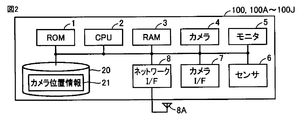
- FIG. 2 is a block diagram illustrating a main hardware configuration of the smartphone 100.
- the smartphone 100 includes a ROM (Read Only Memory) 1, a CPU (Central Processing Unit) 2, a RAM (Random Access Memory) 3, a camera 4, a monitor 5, and a sensor 6.
- ROM 1 stores an operating system (OS), an initial program (boot program) that is executed when the smartphone 100 is started up, and the like.
- the CPU 2 controls the operation of the smartphone 100 by executing various programs such as an operating system and a control program for the smartphone 100 stored in the ROM 1 and the storage device 20.
- the RAM 3 functions as a working memory for executing the program by the CPU 2 and temporarily stores various data necessary for executing the program.
- the camera 4 includes a lens, a CMOS (Complementary Metal-Oxide Semiconductor) or other image sensor, and an autofocus mechanism.
- the monitor 5 displays the output from the image sensor that the camera 4 has as an image.
- the monitor 5 may be configured as a touch panel in combination with a touch sensor (not shown).
- Sensor 6 includes an acceleration sensor, an angular velocity sensor, and other sensors for detecting the tilt of smartphone 100.
- the sensor 6 outputs the detected results such as acceleration and inclination to the CPU 2.
- the external camera device and the smartphone 100 are connected via the camera I / F 7.
- the camera I / F 7 is, for example, a USB (Universal Serial Bus).
- the external camera device can send image data obtained by photographing the subject to the smartphone 100 via the camera I / F 7.
- the network I / F 8 transmits / receives data to / from other communication devices via the antenna 8A.
- Other communication devices are, for example, smart phones, personal computers, server devices, and other electronic devices having communication functions.
- the storage device 20 includes a storage medium such as eMMC (Embedded MultiMediaCard).
- the eMMC includes a NAND flash memory and a control circuit.
- Storage device 20 stores a program and the like for realizing various processes according to the present embodiment. Further, the storage device 20 may store a program such as an operating system.
- the storage device 20 stores camera position information 21 indicating the position of the camera on the smartphone 100. The camera position information 21 is shown as coordinates on the smartphone 100, for example.
- FIG. 3 is a block diagram illustrating a functional configuration of the smartphone 100.
- the CPU 2 includes an extraction unit 210 and a display control unit 220.
- the extraction unit 210 extracts the user's face image from the through image acquired by the camera 4. For example, the extraction unit 210 extracts a face image by searching for a reference image from a through image using a face image registered in advance in the storage device 20 as a reference image. The extraction unit 210 outputs the extracted face image to the display control unit 220.
- the display control unit 220 acquires the camera position information 21 on the smartphone 100 determined in advance, and an area on the monitor 5 that is within a predetermined range from the position on the smartphone 100 indicated by the camera position information 21 Is determined as the object display area 32.
- the display control unit 220 displays a through image acquired from the camera 4 while the camera 4 is photographing a subject in a display area on the monitor 5 different from the object display area 32 (hereinafter also referred to as “through image display area”).
- through image display area a through image displayed as an object in the object display area 32.
- the display control unit 220 may determine the area on the monitor closest to the position indicated by the camera position information 21 as the object display area 32.
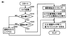
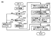
- FIG. 4 is a flowchart showing a part of the process executed by smartphone 100.
- the processing in FIG. 4 is realized by the CPU 2 executing a program. In other aspects, some or all of the processing may be performed by circuit elements or other hardware.
- step S500 the CPU 2 activates the camera based on a user instruction.
- step S510 the CPU 2 determines whether or not the shooting mode is the self-shooting mode. When CPU 2 determines that the shooting mode is the self-shooting mode (YES in step S510), CPU 2 switches control to step S520. If not (NO in step S510), CPU 2 switches control to step S522.
- step S520 the CPU 2 determines, as the extracting unit 210, whether or not a face image is included in the image acquired from the camera 4.
- CPU 2 determines that the face image is included in the image acquired from camera 4 (YES in step S520)
- CPU 2 switches control to step S524. If not (NO in step S520), CPU 2 switches control to step S522.
- step S522 the CPU 2 displays the through image obtained by photographing the subject on the monitor 5 without displaying the object in the object display area 32.
- step S524 the CPU 2 generates a face image from the captured image as the extraction unit 210.
- the CPU 2 generates a face image by cutting out (trimming) the face image from the captured image.
- step S526 as the display control unit 220, the CPU 2 configures a screen layout from the camera position information, and displays the layout on the monitor 5.
- the CPU 2 displays an object in the object display area 32 determined according to the camera position information 21 and displays a through image obtained by photographing the subject on the monitor 5.
- step S528, the CPU 2 executes a shooting function (releases the shutter of the camera 4) based on a user's touch operation on the monitor 5 configured as a touch panel.
- FIG. 5 is a diagram illustrating a display mode of the smartphone 100 ⁇ / b> A when the user is taking a selfie.
- the smartphone 100A is different from the smartphone 100 according to the first embodiment in that an arrow image 37 pointing to the camera 4 is displayed in the object display area instead of displaying a face image as an object. Since other points such as the hardware configuration are the same as those of the smartphone 100 according to the first embodiment, the description will not be repeated.
- the user can more intuitively grasp the place where the line of sight is directed.
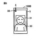
- FIG. 6 is a diagram illustrating a display mode of the smartphone 100 ⁇ / b> B when the user is taking a selfie.
- Smartphone 100B differs from smartphone 100 according to the first embodiment in that icon 38 is displayed in the object display area instead of displaying a face image as an object. Since other points such as the hardware configuration are the same as those of the smartphone 100 according to the first embodiment, description thereof will not be repeated.
- the smartphone 100B cannot display the face image on the monitor because the detected display area is small, if the object that can be recognized by the user even if it is relatively small, such as an icon, is displayed in the object display area.
- the user's line of sight can be guided to the camera 4.
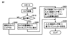
- FIG. 7 is a flowchart showing a part of the process executed by smartphone 100B.
- the processing in FIG. 7 is realized by the CPU 2 executing a program. In one aspect, part or all of the processing may be performed by a circuit element or other hardware.
- the same step number is attached
- step S600 the CPU 2 causes the display control unit 220 to display the icon 38 in the object display area determined from the camera position information while the camera 4 is photographing the subject, and to display the image obtained by photographing the subject. Display in the image display area.
- step S602 the CPU 2 performs guidance of the line of sight by animation, which will be described later, based on camera control such as focus adjustment or a user touch operation on the monitor 5 configured as a touch panel.
- FIG. 8 is a diagram illustrating a display mode of the smartphone 100 ⁇ / b> C when the user is taking a selfie.
- the smart phone 100 ⁇ / b> C is the first embodiment in that instead of displaying the face image cut out from the through image as an object, the through image itself is slid and displayed so that the face position 31 of the through image approaches the camera 4.
- smartphone 100 according to Since it is the same as the smart phone 100 according to 1st Embodiment about another point, description is not repeated.
- smartphone 100C displays the through image itself in the object display area, so that the user can take a picture while looking at the camera 4 and checking his / her facial expression. Can do.
- FIG. 9 is a diagram illustrating a display mode of the smartphone 100D when the user is taking a selfie.
- the smartphone 100D displays the button 39 for accepting the execution of the photographing function for saving the image acquired by the camera 4 in the storage device 20 as an object in the object display area, and the smartphone 100 according to the first embodiment. Is different. Since it is the same as that of the smart phone 100 according to 1st Embodiment about another point, description is not repeated.
- the button 39 for executing the shooting function is displayed in the vicinity of the camera 4, so that the user can execute the shooting function while directing his / her line of sight to the button 39. It is possible to obtain an image in which the intended camera 4 is viewed.
- FIG. 10 is a diagram illustrating a display mode of the smartphone 100E when the user is taking a selfie.
- the smartphone 100E follows the first embodiment in that an animation 35 for guiding the line of sight of the user 30 from the face position 31 toward the camera 4 is displayed in the display area between the face position 31 and the camera 4. Different from 100.
- the smartphone 100E can guide the user's line of sight from the face position 31 to the camera 4 by displaying on the monitor 5 an animation starting from the face position 31 where the user tends to gaze.
- the hardware configuration of the smartphone 100E according to the sixth embodiment is the same as the configuration shown in FIG. Therefore, the description of the hardware configuration will not be repeated.
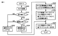
- FIG. 11 is a flowchart showing a part of the process executed by smartphone 100E.
- the processing in FIG. 11 is realized by the CPU 2 executing a program. In one aspect, part or all of the processing may be performed by a circuit element or other hardware.
- the same step number is attached
- step S ⁇ b> 700 the CPU 2 performs an animation in the display area between the face position 31 of the user 30 and the camera 4 included in the through image displayed on the monitor 5 while the camera 4 is photographing the subject. 35 is displayed.
- the CPU 2 may display the animation at a predetermined timing.
- the CPU 2 may display the animation 35 based on the camera 4 being in focus.
- the smartphone 100E may display the animation 35 during focus adjustment.
- the smartphone 100E may display the animation 35 based on a user's touch operation on the monitor 5.
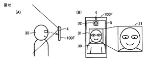
- FIG. 12 is a diagram illustrating a display mode of the smartphone 100F when the user is taking a selfie.
- Smartphone 100F differs from smartphone 100 according to the first embodiment in that the camera position is estimated from the user's line of sight.
- the hardware configuration of the smartphone 100F according to the seventh embodiment is the same as the configuration illustrated in FIG. 2 except that the storage device 20 does not have to have the camera position information 21. Therefore, the description of the hardware configuration will not be repeated.
- the user 30 is taking a selfie using a smartphone 100F provided with a camera 4 at the upper end.
- the user 30 tends to gaze at his / her face shown on the monitor 5 and the line of sight is directed to the opposite side of the camera arrangement position.
- the smartphone 100F estimates that the camera is disposed on the side opposite to the user's line of sight, and displays an object (for example, a face image) in the object display area 32 within a predetermined range from the estimated camera position. .
- the smartphone 100F can estimate the camera position from the user's line of sight, the smartphone 100F can guide the user's line of sight to the camera 4 even when the camera position information cannot be acquired or when the camera position information is not defined. Can do.
- the smartphone 100F can cope with any electronic device whose camera position is not defined, and thus can correspond to any device.
- FIG. 13 is a block diagram illustrating a functional configuration of the smartphone 100F.
- the same number is attached
- the CPU 2 includes an extraction unit 210, a display control unit 220, a line-of-sight detection unit 230, and an estimation unit 240.
- the line-of-sight detection unit 230 detects the user's line of sight directed to the smartphone 100F from the face image extracted by the extraction unit 210.
- the line-of-sight detection unit 230 detects the user's line of sight from the position of the user's pupil included in the face image, for example.
- the line-of-sight detection unit 230 detects the user's line of sight as coordinates on the smartphone 100F.
- the line-of-sight detection unit 230 detects the line of sight by eye tracking.
- the line-of-sight detection unit 230 may detect the line of sight by image processing from a moving image obtained by taking a video of the user's eyeball or a still image obtained by capturing the user.
- the line-of-sight detection unit 230 outputs the detected line of sight to the estimation unit 240.
- the estimation unit 240 estimates the arrangement position of the camera 4 on the smartphone 100F from the line of sight output by the line-of-sight detection unit 230.
- the estimation unit 240 estimates, for example, the position in the edge area excluding the monitor 5 in the area on the smartphone 100F in the direction opposite to the line of sight as the arrangement position of the camera 4.
- the display control unit 220 determines an area on the monitor 5 within a predetermined range from the position of the camera 4 estimated by the estimation unit 240 as an object display area, and an object (for example, a face) Image).
- FIG. 14 is a flowchart showing a part of the process executed by smartphone 100F.
- the processing in FIG. 14 is realized by the CPU 2 executing a program. In other aspects, some or all of the processing may be performed by circuit elements or other hardware. Of the steps shown in FIG. 14, the same steps as those in the flowcharts shown in FIGS. 4 and 11 are given the same step numbers. Therefore, description of similar processing will not be repeated.
- step S800 the CPU 2 detects the user's line of sight as the line-of-sight detection unit 230 by analyzing the face image as the line-of-sight detection unit 230.
- the CPU 2 estimates the camera position from the detected line of sight.
- step S802 the CPU 2 configures a screen layout from the estimated camera position information as the display control unit 220, and displays the screen layout on the monitor 5.
- the CPU 2 displays an object (for example, a face image) in the object display area 32 determined based on the estimated camera position, and displays a through image obtained by photographing the subject on the monitor 5. indicate.
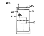
- FIG. 15 is a diagram illustrating a display mode of the smartphone 100G when the user is taking a selfie.
- the smartphone 100G is different from the smartphone 100E according to the sixth embodiment in that the start point of the animation 35 is not the face position of the monitor image but the center 40 of the monitor 5. Since it is the same as the smart phone 100E according to 6th Embodiment about another point, description is not repeated.
- the animation 35 can be displayed without detecting the face image from the image, and the user's line of sight can be displayed with a simpler functional configuration. 4 can be led.
- FIG. 16 is a diagram illustrating a display mode of the smartphone 100H when the user is taking a selfie.
- the smartphone 100H differs from the smartphone 100E according to the sixth embodiment in that the start point of the animation 35 is not the face position of the monitor image but the focus position 43 on the monitor 5. Since it is the same as the smart phone 100E according to 6th Embodiment about another point, description is not repeated.
- the animation 35 can be displayed without detecting a face image from the image, and the user's line of sight can be displayed with a simpler functional configuration. Can lead to.
- FIG. 17 is a flowchart showing a part of the process executed by smartphone 100H.
- the processing in FIG. 17 is realized by the CPU 2 executing a program. In other aspects, some or all of the processing may be performed by circuit elements or other hardware.
- the same step numbers are assigned to the same processes as those in the flowcharts shown in FIGS. 4, 7, 11, and 14. Therefore, description of similar processing will not be repeated.
- step S830 the CPU 2 cuts out an arbitrary range from the image displayed on the monitor 5 as an image to be displayed in the object display area. For example, the CPU 2 determines a fixed range centered on the center of the monitor 5 or a fixed range centered on the focus position.
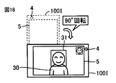
- FIG. 18 is a diagram illustrating a display mode when the smartphone 100I is rotated 90 degrees while the user is taking a selfie.
- Smartphone 100I differs from smartphone 100 according to the first embodiment in that the camera position is acquired according to the inclination of the terminal itself. Since it is the same as the smart phone 100 according to 1st Embodiment about another point, description is not repeated.
- the smartphone 100I Since the position of the camera seen from the user changes when the orientation of the housing of the terminal itself changes, the smartphone 100I re-acquires the camera position according to the inclination of the terminal itself and redisplays the object.
- the smartphone 100I re-displays the object in the object display area, with the area on the monitor 5 within a predetermined range from the re-acquired camera position as a new object display area.
- FIG. 19 is a flowchart showing a part of the process executed by smartphone 100I.
- the processing in FIG. 19 is realized by the CPU 2 executing a program. In other aspects, some or all of the processing may be performed by circuit elements or other hardware.
- the same step number is attached
- step S900 the CPU 2 configures a layout for self-portrait and displays the layout.
- step S902 the CPU 2 acquires a camera position information change notification from the sensor 6 (for example, an acceleration sensor or an angular velocity sensor) for detecting the tilt of the smartphone 100I. Note that the CPU 2 may determine that the camera position has moved when the information from the sensor is different from the past information.
- the sensor 6 for example, an acceleration sensor or an angular velocity sensor
- step S904 the CPU 2 acquires camera position information from the sensor 6 for detecting the tilt of the smartphone 100I.
- the CPU 2 may specify the camera position according to the tilt angle at which the user tilts the smartphone 100I based on the past camera position.
- FIG. 20 is a diagram illustrating a display mode of the smartphone 100J when the user is taking a selfie.
- Smartphone 100J is different from smartphone 100 according to the first embodiment in that a camera is connected as an external device.
- the hardware configuration of the smartphone 100J is the same as the configuration shown in FIG. Therefore, the description of the hardware configuration will not be repeated.
- the smartphone 100J includes a camera I / F 7 that can connect an external camera device.
- the camera 4 ⁇ / b> A that is an external device is connected to the smartphone 100 ⁇ / b> J via the camera I / F 7.
- the camera 4A includes a web camera and other electronic devices having a photographing function.
- the camera 4A can specify the position of the camera 4A by a sensor such as an acceleration sensor included in the camera 4A, and outputs position information representing the specified position to the smartphone 100J.
- the smartphone 100J determines an area on the monitor 5 within a predetermined range from the position information output from the camera 4A as an object display area, and displays the object in the object display area.
- the smartphone 100J may be configured to specify the position of the camera 4A by an arbitrary protocol with the camera 4A and determine the object display area based on the position.
- FIG. 21 is a flowchart showing a part of the process executed by smartphone 100J.
- the processing in FIG. 21 is realized by the CPU 2 executing a program. In other aspects, some or all of the processing may be performed by circuit elements or other hardware.
- the same step numbers are assigned to the same processes as those in the flowcharts shown in FIGS. 4, 7, 11, 14, and 17. Therefore, description of similar processing will not be repeated.
- step S1000 the CPU 2 acquires position information from the camera 4A.
- step S1002 the CPU 2 determines an area on the monitor 5 within a predetermined range from the position information output from the camera 4A as an object display area, and displays an object (for example, a face image) in the object display area. To do.
Landscapes
- Engineering & Computer Science (AREA)
- Signal Processing (AREA)
- Multimedia (AREA)
- Human Computer Interaction (AREA)
- Computer Networks & Wireless Communication (AREA)
- Studio Devices (AREA)
- Telephone Function (AREA)
- User Interface Of Digital Computer (AREA)
- Indication In Cameras, And Counting Of Exposures (AREA)
Abstract
ユーザがカメラを正視した状態で自分撮りを行なうことができる電子機器を提供する。スマートフォンは、モニタと、モニタの表示面側に配置されたカメラと、スマートフォンを制御するためのCPU(2)とを備える。CPU(2)は、カメラが被写体を撮影中に、スマートフォンのユーザの視線をカメラに導くためのオブジェクトを、スマートフォンにおけるカメラの配置位置から予め定められた範囲内にあるモニタ上の第1の表示領域に表示するための表示制御部(220)を含む。
Description
本開示は電子機器の制御に関し、より特定的には、撮影機能およびタッチ操作機能を備える電子機器の制御に関する。
近年、撮影機能を備えた、スマートフォン、タブレット端末その他の携帯型の電子機器が普及している。カメラが、所謂インカメラとして表示装置側に配置されている場合、電子機器のユーザは、リアルタイムに表示装置に表示されたスルー画像を確認しながら自分自身を撮影する、所謂自分撮りと呼ばれる撮影を実行できる。ユーザが自分撮りを行なう場合には、ユーザは、カメラではなくスルー画像を注視してしまう傾向にあり、撮影画像に写っているユーザの視線がユーザの意図しないものになることがある。
特許文献1(特開2007-116601号公報)は、このような問題を解決するために、「撮影光軸の撮影方向と、表示部の表示方向が揃うような、自分撮り撮影の場合でも、被写体の視線が表示部の表示を見たままで視線をはずした撮影にならない撮影装置」を開示している。当該撮像装置は、撮影を実行する直前にスルー画像を消すことによりユーザの視線をスルー画像から逸らす。
ところで、近年の小型化されたスマートフォンなどの電子機器においては、カメラがいずれの場所に配置されているのかを把握することが困難な場合がある。特許文献1に開示される撮影装置のようにスルー画像が消されたからといって、ユーザは、当該撮像装置におけるカメラの配置位置を把握できるわけではない。このため、ユーザは、カメラを正視した状態で撮影を実行できず、依然として、撮影画像に写っているユーザの視線が意図しないものになる可能性がある。したがって、ユーザが自分撮りを行なう場合に、カメラを正視した状態でユーザを撮影するための技術が必要とされている。
本開示は、上述のような問題点を解決するためになされたものであって、ある局面における目的は、ユーザがカメラを正視した状態で自分撮りを行なうことができる電子機器を提供することである。
一実施の形態に従うと、モニタと、モニタの表示面側に配置されたカメラと、電子機器を制御するための制御装置とを備える電子機器が提供される。制御装置は、カメラが被写体を撮影中に、電子機器のユーザの視線をカメラに導くためのオブジェクトを、電子機器におけるカメラの配置位置から予め定められた範囲内にあるモニタ上の第1の表示領域に表示するための表示制御手段を含む。
ある局面において、電子機器は、ユーザがカメラを正視した状態で自分撮りを行なうことができる。
本発明の上記および他の目的、特徴、局面および利点は、添付の図面と関連して理解される本発明に関する次の詳細な説明から明らかとなるであろう。
以下、図面を参照しつつ、本実施の形態について説明する。以下の説明では、同一の部品および構成要素には同一の符号を付してある。それらの名称および機能も同じである。したがって、これらについての詳細な説明は繰り返さない。
なお、以下では、電子機器の一例として機能するスマートフォンの詳細について説明するが、電子機器は、スマートフォンに限定されるものではない。たとえば、電子機器は、タブレット端末、デジタルカメラ、ゲーム機、電子辞書、パソコン、PDA(Personal Digital Assistants)、自分撮りが可能なその他の携帯端末装置も含み得る。また、以下で説明される各実施の形態は、選択的に組み合わされてもよい。
<第1の実施の形態>
[概要]
図1を参照して、第1の実施の形態に係るスマートフォン100の概要について説明する。図1は、ユーザが自分撮りを行なっている場合のスマートフォン100の表示態様を示している図である。
[概要]
図1を参照して、第1の実施の形態に係るスマートフォン100の概要について説明する。図1は、ユーザが自分撮りを行なっている場合のスマートフォン100の表示態様を示している図である。
図1(A)に示されるように、スマートフォン100は、カメラ4と、モニタ5とを備える。モニタ5は、スマートフォン100のユーザ30を撮影して得られたスルー画像をリアルタイムに表示している。カメラ4は、モニタ5の表示面側に配置され、これにより、ユーザ30は、スルー画像を確認しながら自分撮りを行なうことができる。
ユーザ30は、自分撮りを行なっている場合に、カメラ4ではなく、モニタ5に表示されたスルー画像を見てしまう傾向にある。ユーザ30がカメラ4を正視していない状態で撮影を実行すると、視線が不自然な撮影画像が得られる。
図1(B)に示されるように、スマートフォン100は、カメラ4が被写体を撮影中に、ユーザ30の視線をカメラ4に導くためのオブジェクトをカメラ4の配置位置から予め定められた範囲内にあるモニタ5上のオブジェクト表示領域32に表示する。これにより、ユーザは、カメラの近傍に表示されたオブジェクトを注視するようになり、カメラ4を正視した状態で撮影を行なうことが可能になる。
たとえば、オブジェクトとしては、ユーザ30の顔画像が挙げられる。ユーザの顔画像がオブジェクト表示領域32に表示されることにより、ユーザは、カメラ4に視線を向けながら、自身の表情などを確認することができ、カメラ4を正視した状態で撮影を実行でき、ユーザ30が意図した目線が自然な画像を得ることができる。
なお、オブジェクトは、顔画像に限定されない。たとえば、オブジェクトは、後述する、アニメーション、アイコン、矢印、撮影指示を受け付けるためのボタン、スルー画像自体などであってもよい。
[ハードウェア構成]
図2を参照して、第1の実施の形態に従うスマートフォン100のハードウェア構成の一例について説明する。図2は、スマートフォン100の主要なハードウェア構成を示すブロック図である。図2に示されるように、スマートフォン100は、ROM(Read Only Memory)1と、CPU(Central Processing Unit)2と、RAM(Random Access Memory)3と、カメラ4と、モニタ5と、センサ6と、カメラインタフェース(I/F)7と、ネットワークインタフェース(I/F)8と、記憶装置20とを備える。
図2を参照して、第1の実施の形態に従うスマートフォン100のハードウェア構成の一例について説明する。図2は、スマートフォン100の主要なハードウェア構成を示すブロック図である。図2に示されるように、スマートフォン100は、ROM(Read Only Memory)1と、CPU(Central Processing Unit)2と、RAM(Random Access Memory)3と、カメラ4と、モニタ5と、センサ6と、カメラインタフェース(I/F)7と、ネットワークインタフェース(I/F)8と、記憶装置20とを備える。
ROM1は、オペレーティングシステム(OS:Operating System)、スマートフォン100の起動時に実行される初期プログラム(ブートプログラム)などを格納する。CPU2は、ROM1や記憶装置20などに格納された、オペレーティングシステムやスマートフォン100の制御プログラムなどの各種プログラムを実行することで、スマートフォン100の動作を制御する。RAM3は、CPU2でプログラムを実行するためのワーキングメモリとして機能し、プログラムの実行に必要な各種データを一時的に格納する。
カメラ4は、レンズと、CMOS(Complementary Metal-Oxide Semiconductor)その他の撮像素子と、オートフォーカス機構とを含む。モニタ5は、カメラ4が有する撮像素子からの出力を画像として表示する。また、モニタ5は、タッチセンサ(図示しない)と組み合わされてタッチパネルとして構成されてもよい。
センサ6は、加速度センサ、角速度センサ、スマートフォン100の傾きを検出するためのその他のセンサを含む。センサ6は、加速度、傾きなどの検出した結果をCPU2に出力する。
外部のカメラ装置とスマートフォン100とは、カメラI/F7を介して接続される。カメラI/F7は、たとえば、USB(Universal Serial Bus)である。外部のカメラ装置は、被写体を撮影して得た画像データをカメラI/F7を介してスマートフォン100に送ることができる。
ネットワークI/F8は、アンテナ8Aを介して、他の通信機器とデータの送受信を行なう。他の通信機器は、たとえば、スマートフォン、パソコン、サーバ装置、その他通信機能を有する電子機器などである。
記憶装置20は、たとえば、eMMC(Embedded MultiMediaCard)などの記憶媒体を含む。eMMCは、NANDフラッシュメモリと、制御回路とを含む。記憶装置20は、本実施の形態に従う各種の処理を実現するためのプログラムなどを格納する。また、記憶装置20は、オペレーティングシステムなどのプログラムを格納していてもよい。記憶装置20には、スマートフォン100上のカメラの位置を示すカメラ位置情報21が格納される。カメラ位置情報21は、たとえば、スマートフォン100上の座標として示される。
[機能構成]
図3を参照して、スマートフォン100の機能構成の一例について説明する。図3は、スマートフォン100の機能構成を示すブロック図である。CPU2は、抽出部210と、表示制御部220とを含む。
図3を参照して、スマートフォン100の機能構成の一例について説明する。図3は、スマートフォン100の機能構成を示すブロック図である。CPU2は、抽出部210と、表示制御部220とを含む。
抽出部210は、カメラ4によって取得されたスルー画像からユーザの顔画像を抽出する。抽出部210は、たとえば、記憶装置20に予め登録された顔画像を基準画像として、スルー画像から基準画像を探索することにより顔画像を抽出する。抽出部210は、抽出した顔画像を表示制御部220に出力する。
表示制御部220は、予め定められたスマートフォン100上のカメラ位置情報21を取得して、当該カメラ位置情報21で示されるスマートフォン100上の位置から予め定められた範囲内にあるモニタ5上の領域をオブジェクト表示領域32として決定する。表示制御部220は、カメラ4が被写体を撮影中に、カメラ4から取得したスルー画像をオブジェクト表示領域32とは異なるモニタ5上の表示領域(以下、「スルー画像表示領域」ともいう。)に表示すると共に、抽出部210によって抽出された顔画像をオブジェクトとしてオブジェクト表示領域32に表示する。
なお、表示制御部220は、カメラ位置情報21で示される位置から最も近いモニタ上の領域をオブジェクト表示領域32として決定してもよい。
[制御構造]
図4を参照して、スマートフォン100の制御構造について説明する。図4は、スマートフォン100が実行する処理の一部を表わすフローチャートである。図4の処理は、CPU2がプログラムを実行することにより実現される。他の局面において、処理の一部又は全部が、回路素子その他のハードウェアによって実行されてもよい。
図4を参照して、スマートフォン100の制御構造について説明する。図4は、スマートフォン100が実行する処理の一部を表わすフローチャートである。図4の処理は、CPU2がプログラムを実行することにより実現される。他の局面において、処理の一部又は全部が、回路素子その他のハードウェアによって実行されてもよい。
ステップS500において、CPU2は、ユーザの指示に基づいてカメラを起動する。ステップS510において、CPU2は、撮影モードが自分撮りモードであるか否かを判断する。CPU2は、撮影モードが自分撮りモードであると判断した場合には(ステップS510においてYES)、制御をステップS520に切り替える。そうでない場合には(ステップS510においてNO)、CPU2は、制御をステップS522に切り替える。
ステップS520において、CPU2は、抽出部210として、カメラ4から取得した画像に顔画像が含まれるか否かを判断する。CPU2は、カメラ4から取得した画像に顔画像が含まれると判断した場合には(ステップS520においてYES)、制御をステップS524に切り替える。そうでない場合には(ステップS520においてNO)、CPU2は、制御をステップS522に切り替える。
ステップS522において、CPU2は、オブジェクト表示領域32にオブジェクトを表示せずに、被写体を撮影して得られたスルー画像をモニタ5に表示する。ステップS524において、CPU2は、抽出部210として、撮影画像から顔画像を生成する。ある局面において、CPU2は、撮影画像から顔画像を切り出す(トリミング)ことにより顔画像を生成する。
ステップS526において、CPU2は、表示制御部220として、カメラ位置情報から画面レイアウトを構成し、当該レイアウトをモニタ5に表示する。ある局面において、CPU2は、カメラ位置情報21に応じて決定したオブジェクト表示領域32にオブジェクトを表示すると共に、被写体を撮影して得られたスルー画像をモニタ5に表示する。ステップS528において、CPU2は、タッチパネルとして構成されるモニタ5に対するユーザのタッチ操作に基づいて、撮影機能を実行する(カメラ4のシャッターを切る)。
<第2の実施の形態>
図5を参照して、第2の実施の形態に従うスマートフォン100Aの概要について説明する。図5は、ユーザが自分撮りをしている場合のスマートフォン100Aの表示態様を示している図である。スマートフォン100Aは、オブジェクトとして顔画像を表示する代わりに、カメラ4を指す矢印画像37をオブジェクト表示領域に表示する点で第1の実施の形態に従うスマートフォン100とは異なる。ハードウェア構成などのその他の点については第1の実施の形態に従うスマートフォン100と同じであるので、説明を繰り返さない。
図5を参照して、第2の実施の形態に従うスマートフォン100Aの概要について説明する。図5は、ユーザが自分撮りをしている場合のスマートフォン100Aの表示態様を示している図である。スマートフォン100Aは、オブジェクトとして顔画像を表示する代わりに、カメラ4を指す矢印画像37をオブジェクト表示領域に表示する点で第1の実施の形態に従うスマートフォン100とは異なる。ハードウェア構成などのその他の点については第1の実施の形態に従うスマートフォン100と同じであるので、説明を繰り返さない。
矢印画像37のようにカメラ4を直接的に指す画像がオブジェクト表示領域に表示されることで、ユーザは、視線を向ける場所をより直感的に把握することができる。
<第3の実施の形態>
図6を参照して、第3の実施の形態に従うスマートフォン100Bの概要について説明する。図6は、ユーザが自分撮りをしている場合のスマートフォン100Bの表示態様を示している図である。スマートフォン100Bは、オブジェクトとして顔画像を表示する代わりに、アイコン38をオブジェクト表示領域に表示する点で第1の実施の形態に従うスマートフォン100とは異なる。ハードウェア構成などのその他の点については第1の実施の形態に従うスマートフォン100と同じであるので説明を繰り返さない。
図6を参照して、第3の実施の形態に従うスマートフォン100Bの概要について説明する。図6は、ユーザが自分撮りをしている場合のスマートフォン100Bの表示態様を示している図である。スマートフォン100Bは、オブジェクトとして顔画像を表示する代わりに、アイコン38をオブジェクト表示領域に表示する点で第1の実施の形態に従うスマートフォン100とは異なる。ハードウェア構成などのその他の点については第1の実施の形態に従うスマートフォン100と同じであるので説明を繰り返さない。
スマートフォン100Bは、検出した表示領域が狭いために顔画像をモニタに表示できないような場合であっても、アイコンのような比較的小さくてもユーザが認識できるものがオブジェクト表示領域に表示されれば、ユーザの視線をカメラ4に導くことができる。
[制御構造]
図7を参照して、スマートフォン100Bの制御構造について説明する。図7は、スマートフォン100Bが実行する処理の一部を表わすフローチャートである。図7の処理は、CPU2がプログラムを実行することにより実現される。ある局面において、処理の一部又は全部が、回路素子その他のハードウェアによって実行されてもよい。なお、図7に示される各ステップのうち図4に示されるフローチャートにおける処理と同様の処理には同じステップ番号を付してある。したがって、同様の処理の説明は繰り返さない。
図7を参照して、スマートフォン100Bの制御構造について説明する。図7は、スマートフォン100Bが実行する処理の一部を表わすフローチャートである。図7の処理は、CPU2がプログラムを実行することにより実現される。ある局面において、処理の一部又は全部が、回路素子その他のハードウェアによって実行されてもよい。なお、図7に示される各ステップのうち図4に示されるフローチャートにおける処理と同様の処理には同じステップ番号を付してある。したがって、同様の処理の説明は繰り返さない。
ステップS600において、CPU2は、表示制御部220として、カメラ4が被写体を撮影中に、カメラ位置情報より決定したオブジェクト表示領域にアイコン38を表示すると共に、被写体を撮影して得られた画像をスルー画像表示領域に表示する。
ステップS602において、CPU2は、フォーカス調整などのカメラ制御、または、タッチパネルとして構成されるモニタ5へのユーザのタッチ操作に基づいて、後述するアニメーションによる視線の誘導を実行する。
<第4の実施の形態>
図8を参照して、第4の実施の形態に従うスマートフォン100Cの概要について説明する。図8は、ユーザが自分撮りをしている場合のスマートフォン100Cの表示態様を示している図である。スマートフォン100Cは、スルー画像から切り出した顔画像をオブジェクトとして表示する代わりに、スルー画像の顔位置31がカメラ4に近付くようにスルー画像自体をスライドして表示する点で、第1の実施の形態に従うスマートフォン100とは異なる。その他の点については第1の実施の形態に従うスマートフォン100と同じであるので説明を繰り返さない。
図8を参照して、第4の実施の形態に従うスマートフォン100Cの概要について説明する。図8は、ユーザが自分撮りをしている場合のスマートフォン100Cの表示態様を示している図である。スマートフォン100Cは、スルー画像から切り出した顔画像をオブジェクトとして表示する代わりに、スルー画像の顔位置31がカメラ4に近付くようにスルー画像自体をスライドして表示する点で、第1の実施の形態に従うスマートフォン100とは異なる。その他の点については第1の実施の形態に従うスマートフォン100と同じであるので説明を繰り返さない。
本実施の形態によれば、スマートフォン100Cがスルー画像自体をオブジェクト表示領域に表示することにより、ユーザは、カメラ4に視線を向けながら、かつ、自身の表情などを確認しながら撮影を実行することができる。
<第5の実施の形態>
図9を参照して、第5の実施の形態に従うスマートフォン100Dの概要について説明する。図9は、ユーザが自分撮りをしている場合のスマートフォン100Dの表示態様を示している図である。スマートフォン100Dは、カメラ4によって取得された画像を記憶装置20に保存するための撮影機能の実行を受け付けるボタン39をオブジェクトとしてオブジェクト表示領域に表示する点で、第1の実施の形態に従うスマートフォン100とは異なる。その他の点については第1の実施の形態に従うスマートフォン100と同じであるので、説明を繰り返さない。
図9を参照して、第5の実施の形態に従うスマートフォン100Dの概要について説明する。図9は、ユーザが自分撮りをしている場合のスマートフォン100Dの表示態様を示している図である。スマートフォン100Dは、カメラ4によって取得された画像を記憶装置20に保存するための撮影機能の実行を受け付けるボタン39をオブジェクトとしてオブジェクト表示領域に表示する点で、第1の実施の形態に従うスマートフォン100とは異なる。その他の点については第1の実施の形態に従うスマートフォン100と同じであるので、説明を繰り返さない。
本実施の形態によれば、撮影機能を実行するためのボタン39がカメラ4の近傍に表示されることで、ユーザは、ボタン39に視線を向けながら撮影機能を実行することができ、ユーザ30が意図するカメラ4を正視した画像を得ることができる。
<第6の実施の形態>
[概要]
図10を参照して、第6の実施の形態に従うスマートフォン100Eの概要について説明する。図10は、ユーザが自分撮りをしている場合のスマートフォン100Eの表示態様を示している図である。スマートフォン100Eは、顔位置31とカメラ4との間の表示領域に、ユーザ30の視線を顔位置31からカメラ4の方向に導くためのアニメーション35を表示する点で第1の実施の形態に従うスマートフォン100と異なる。
[概要]
図10を参照して、第6の実施の形態に従うスマートフォン100Eの概要について説明する。図10は、ユーザが自分撮りをしている場合のスマートフォン100Eの表示態様を示している図である。スマートフォン100Eは、顔位置31とカメラ4との間の表示領域に、ユーザ30の視線を顔位置31からカメラ4の方向に導くためのアニメーション35を表示する点で第1の実施の形態に従うスマートフォン100と異なる。
スマートフォン100Eは、ユーザが注視する傾向にある顔位置31を始点とするアニメーションをモニタ5に表示することで、顔位置31からカメラ4にユーザの視線を導くことができる。なお、第6の実施の形態に係るスマートフォン100Eのハードウェア構成は、図2に示される構成と同様である。したがって、ハードウェア構成の説明は繰り返さない。
[制御構造]
図11を参照して、スマートフォン100Eの制御構造について説明する。図11は、スマートフォン100Eが実行する処理の一部を表わすフローチャートである。図11の処理は、CPU2がプログラムを実行することにより実現される。ある局面において、処理の一部又は全部が、回路素子その他のハードウェアによって実行されてもよい。なお、図11に示される各ステップのうち図4に示されるフローチャートにおける処理と同様の処理には同じステップ番号を付してある。したがって、同様の処理の説明は繰り返さない。
図11を参照して、スマートフォン100Eの制御構造について説明する。図11は、スマートフォン100Eが実行する処理の一部を表わすフローチャートである。図11の処理は、CPU2がプログラムを実行することにより実現される。ある局面において、処理の一部又は全部が、回路素子その他のハードウェアによって実行されてもよい。なお、図11に示される各ステップのうち図4に示されるフローチャートにおける処理と同様の処理には同じステップ番号を付してある。したがって、同様の処理の説明は繰り返さない。
ステップS700において、CPU2は、表示制御部220として、カメラ4が被写体を撮影中に、モニタ5に表示されたスルー画像に含まれるユーザ30の顔位置31とカメラ4との間の表示領域にアニメーション35を表示する。なお、CPU2は、アニメーションを所定のタイミングで表示してもよい。たとえば、CPU2は、カメラ4のピントがあったことに基づいてアニメーション35を表示してもよい。ある局面において、スマートフォン100Eは、フォーカスの調整中にアニメーション35を表示してもよい。他の局面において、スマートフォン100Eは、ユーザのモニタ5に対するタッチ操作に基づいて、アニメーション35を表示してもよい。
<第7の実施の形態>
[概要]
図12を参照して、第7の実施の形態に従うスマートフォン100Fについて説明する。図12は、ユーザが自分撮りをしている場合のスマートフォン100Fの表示態様を示している図である。スマートフォン100Fは、ユーザの視線からカメラ位置を推定する点で第1の実施の形態に従うスマートフォン100と異なる。
[概要]
図12を参照して、第7の実施の形態に従うスマートフォン100Fについて説明する。図12は、ユーザが自分撮りをしている場合のスマートフォン100Fの表示態様を示している図である。スマートフォン100Fは、ユーザの視線からカメラ位置を推定する点で第1の実施の形態に従うスマートフォン100と異なる。
なお、第7の実施の形態に係るスマートフォン100Fのハードウェア構成は、記憶装置20がカメラ位置情報21を有さなくてもよい点を除いて図2に示される構成と同様である。したがって、ハードウェア構成の説明は繰り返さない。
図12(A)に示されるように、ユーザ30は、上端にカメラ4が設けられたスマートフォン100Fを用いて自分撮りを行なっている。このとき、ユーザ30は、モニタ5に写った自身の顔を注視する傾向にあり、視線はカメラの配置位置と反対側に向く。たとえば、図12(B)に示されるように、カメラ4がスマートフォン100Fの上部に配置されている場合には、視線が下向きになる可能性が高い。スマートフォン100Fは、ユーザの視線とは反対側にカメラが配置されていると推定し、推定したカメラ位置から予め定められた範囲内にあるオブジェクト表示領域32にオブジェクト(たとえば、顔画像)を表示する。
スマートフォン100Fは、ユーザの視線からカメラ位置を推定できるので、カメラ位置情報が取得できない場合、または、カメラ位置情報が規定されていない場合などであっても、ユーザの視線をカメラ4に誘導することができる。また、スマートフォン100Fは、カメラ位置が規定されていないような電子機器であっても対応できるので、あらゆる機器に対応できるようになる。
[機能構成]
図13を参照して、スマートフォン100Fの機能構成の一例について説明する。図13は、スマートフォン100Fの機能構成を示すブロック図である。なお、図3に示される構成と同じ構成には同じ番号を付してある。したがって、同じ構成の説明は繰り返さない。
図13を参照して、スマートフォン100Fの機能構成の一例について説明する。図13は、スマートフォン100Fの機能構成を示すブロック図である。なお、図3に示される構成と同じ構成には同じ番号を付してある。したがって、同じ構成の説明は繰り返さない。
CPU2は、抽出部210と、表示制御部220と、視線検出部230と、推定部240とを含む。視線検出部230は、抽出部210によって抽出された顔画像から、スマートフォン100Fに向けられたユーザの視線を検出する。視線検出部230は、たとえば、顔画像に含まれるユーザの瞳孔の位置からユーザの視線を検出する。視線検出部230は、一例として、ユーザの視線をスマートフォン100F上の座標として検出する。
ある局面において、視線検出部230は、アイトラッキングにより視線を検出する。また、視線検出部230は、ユーザの眼球をビデオ撮影した動画像や、ユーザを撮像して得られた静止画像から画像処理によって視線を検出してもよい。視線検出部230は、検出した視線を推定部240に出力する。
推定部240は、スマートフォン100Fにおけるカメラ4の配置位置を視線検出部230によって出力された視線から推定する。推定部240は、たとえば、視線とは反対方向の、スマートフォン100F上の領域のうちモニタ5を除く縁領域内の位置をカメラ4の配置位置として推定する。
表示制御部220は、推定部240によって推定されたカメラ4の配置位置から予め定められた範囲内にあるモニタ5上の領域をオブジェクト表示領域として決定し、当該オブジェクト表示領域にオブジェクト(たとえば、顔画像)を表示する。
[制御構造]
図14を参照して、スマートフォン100Fの制御構造について説明する。図14は、スマートフォン100Fが実行する処理の一部を表わすフローチャートである。図14の処理は、CPU2がプログラムを実行することにより実現される。他の局面において、処理の一部又は全部が、回路素子その他のハードウェアによって実行されてもよい。なお、図14に示される各ステップのうち図4および図11に示されるフローチャートにおける処理と同様の処理には同じステップ番号を付してある。したがって、同様の処理の説明は繰り返さない。
図14を参照して、スマートフォン100Fの制御構造について説明する。図14は、スマートフォン100Fが実行する処理の一部を表わすフローチャートである。図14の処理は、CPU2がプログラムを実行することにより実現される。他の局面において、処理の一部又は全部が、回路素子その他のハードウェアによって実行されてもよい。なお、図14に示される各ステップのうち図4および図11に示されるフローチャートにおける処理と同様の処理には同じステップ番号を付してある。したがって、同様の処理の説明は繰り返さない。
ステップS800において、CPU2は、視線検出部230として、顔画像を解析することによりユーザの視線を視線検出部230として検出する。CPU2は、推定部240として、検出した視線からカメラ位置を推定する。
ステップS802において、CPU2は、表示制御部220として、推定されたカメラ位置情報から画面レイアウトを構成し、当該画面レイアウトをモニタ5に表示する。ある局面において、CPU2は、推定されたカメラの配置位置に基づいて決定したオブジェクト表示領域32にオブジェクト(たとえば、顔画像)を表示すると共に、被写体を撮影して得られたスルー画像をモニタ5に表示する。
<第8の実施の形態>
図15を参照して、第8の実施の形態に従うスマートフォン100Gの概要について説明する。図15は、ユーザが自分撮りをしている場合のスマートフォン100Gの表示態様を示している図である。スマートフォン100Gは、アニメーション35の始点が、モニタ画像の顔位置ではなく、モニタ5の中心40である点で、第6の実施の形態に従うスマートフォン100Eとは異なる。その他の点については第6の実施の形態に従うスマートフォン100Eと同じであるので説明を繰り返さない。
図15を参照して、第8の実施の形態に従うスマートフォン100Gの概要について説明する。図15は、ユーザが自分撮りをしている場合のスマートフォン100Gの表示態様を示している図である。スマートフォン100Gは、アニメーション35の始点が、モニタ画像の顔位置ではなく、モニタ5の中心40である点で、第6の実施の形態に従うスマートフォン100Eとは異なる。その他の点については第6の実施の形態に従うスマートフォン100Eと同じであるので説明を繰り返さない。
本実施の形態によれば、アニメーションの始点をモニタ5の中心とすることで、画像から顔画像を検出せずともアニメーション35を表示できるようになり、より簡易な機能構成でユーザの視線をカメラ4に導くことができる。
<第9の実施の形態>
[概要]
図16を参照して、第9の実施の形態に従うスマートフォン100Hの概要について説明する。図16は、ユーザが自分撮りをしている場合のスマートフォン100Hの表示態様を示している図である。スマートフォン100Hは、アニメーション35の始点が、モニタ画像の顔位置ではなくモニタ5上のフォーカス位置43である点で、第6の実施の形態に従うスマートフォン100Eとは異なる。その他の点については第6の実施の形態に従うスマートフォン100Eと同じであるので説明を繰り返さない。
[概要]
図16を参照して、第9の実施の形態に従うスマートフォン100Hの概要について説明する。図16は、ユーザが自分撮りをしている場合のスマートフォン100Hの表示態様を示している図である。スマートフォン100Hは、アニメーション35の始点が、モニタ画像の顔位置ではなくモニタ5上のフォーカス位置43である点で、第6の実施の形態に従うスマートフォン100Eとは異なる。その他の点については第6の実施の形態に従うスマートフォン100Eと同じであるので説明を繰り返さない。
本実施の形態によれば、アニメーションの始点をフォーカス位置43とすることで、画像から顔画像を検出せずともアニメーション35を表示できるようになり、より簡易な機能構成でユーザの視線をカメラ4に導くことができる。
[制御構造]
図17を参照して、スマートフォン100Hの制御構造について説明する。図17は、スマートフォン100Hが実行する処理の一部を表わすフローチャートである。図17の処理は、CPU2がプログラムを実行することにより実現される。他の局面において、処理の一部又は全部が、回路素子その他のハードウェアによって実行されてもよい。なお、図17に示される各ステップのうち図4、図7、図11、および図14に示されるフローチャートにおける処理と同様の処理には同じステップ番号を付してある。したがって、同様の処理の説明は繰り返さない。
図17を参照して、スマートフォン100Hの制御構造について説明する。図17は、スマートフォン100Hが実行する処理の一部を表わすフローチャートである。図17の処理は、CPU2がプログラムを実行することにより実現される。他の局面において、処理の一部又は全部が、回路素子その他のハードウェアによって実行されてもよい。なお、図17に示される各ステップのうち図4、図7、図11、および図14に示されるフローチャートにおける処理と同様の処理には同じステップ番号を付してある。したがって、同様の処理の説明は繰り返さない。
ステップS830において、CPU2は、モニタ5に表示された画像から任意の範囲をオブジェクト表示領域に表示する画像として切り出す。たとえば、CPU2は、モニタ5の中心を中心とした一定の範囲、または、フォーカス位置を中心とした一定の範囲を切り出す範囲として決定する。
<第10の実施の形態>
[概要]
図18を参照して、第10の実施の形態に従うスマートフォン100Iの概要について説明する。図18は、ユーザが自分撮りをしている間にスマートフォン100Iを90度回転させた場合の表示態様を示している図である。スマートフォン100Iは、自端末の傾きに応じてカメラ位置を取得する点で、第1の実施の形態に従うスマートフォン100とは異なる。その他の点については第1の実施の形態に従うスマートフォン100と同じであるので説明を繰り返さない。
[概要]
図18を参照して、第10の実施の形態に従うスマートフォン100Iの概要について説明する。図18は、ユーザが自分撮りをしている間にスマートフォン100Iを90度回転させた場合の表示態様を示している図である。スマートフォン100Iは、自端末の傾きに応じてカメラ位置を取得する点で、第1の実施の形態に従うスマートフォン100とは異なる。その他の点については第1の実施の形態に従うスマートフォン100と同じであるので説明を繰り返さない。
スマートフォン100Iは、自端末の筺体の向きが変わると、ユーザから見たカメラの位置も変わるため、カメラ位置を自端末の傾きに応じて再取得してオブジェクトを再表示する。スマートフォン100Iは、再取得したカメラ位置から予め定められた範囲内にあるモニタ5上の領域を新たなオブジェクト表示領域として、当該オブジェクト表示領域にオブジェクトを再表示する。
これにより、スマートフォン100Iの傾きがどの向きであってもカメラ4付近にオブジェクトを表示することが可能になる。すなわち、ユーザは、カメラ4を正視した状態で撮影機能を実行することができるようになる。
[制御構造]
図19を参照して、スマートフォン100Iの制御構造について説明する。図19は、スマートフォン100Iが実行する処理の一部を表わすフローチャートである。図19の処理は、CPU2がプログラムを実行することにより実現される。他の局面において、処理の一部又は全部が、回路素子その他のハードウェアによって実行されてもよい。なお、図19に示される各ステップのうち図4、図7、図11、図14、および図17に示されるフローチャートにおける処理と同様の処理には同じステップ番号を付してある。したがって、同様の処理の説明は繰り返さない。
図19を参照して、スマートフォン100Iの制御構造について説明する。図19は、スマートフォン100Iが実行する処理の一部を表わすフローチャートである。図19の処理は、CPU2がプログラムを実行することにより実現される。他の局面において、処理の一部又は全部が、回路素子その他のハードウェアによって実行されてもよい。なお、図19に示される各ステップのうち図4、図7、図11、図14、および図17に示されるフローチャートにおける処理と同様の処理には同じステップ番号を付してある。したがって、同様の処理の説明は繰り返さない。
ステップS900において、CPU2は、自分撮り用のレイアウトを構成し、当該レイアウトを表示する。ステップS902において、CPU2は、スマートフォン100Iの傾きを検出するためのセンサ6(たとえば、加速度センサ、角速度センサ)からカメラ位置情報の変更通知を取得する。なお、CPU2は、センサからの情報が過去の情報とは異なるものになった場合に、カメラ位置が移動したと判断してもよい。
ステップS904において、CPU2は、スマートフォン100Iの傾きを検出するためのセンサ6からカメラ位置情報を取得する。たとえば、CPU2は、過去のカメラ位置を元にして、ユーザがスマートフォン100Iを傾けた傾き角度に応じてカメラ位置を特定してもよい。
<第11の実施の形態>
[概要]
図20を参照して、第11の実施の形態に従うスマートフォン100Jの概要について説明する。図20は、ユーザが自分撮りをしている場合のスマートフォン100Jの表示態様を示している図である。スマートフォン100Jは、カメラが外部デバイスとして接続される点で、第1の実施の形態に従うスマートフォン100とは異なる。なお、スマートフォン100Jのハードウェア構成は、図2に示される構成と同様である。したがって、ハードウェア構成の説明は繰り返さない。
[概要]
図20を参照して、第11の実施の形態に従うスマートフォン100Jの概要について説明する。図20は、ユーザが自分撮りをしている場合のスマートフォン100Jの表示態様を示している図である。スマートフォン100Jは、カメラが外部デバイスとして接続される点で、第1の実施の形態に従うスマートフォン100とは異なる。なお、スマートフォン100Jのハードウェア構成は、図2に示される構成と同様である。したがって、ハードウェア構成の説明は繰り返さない。
図20に示されるように、スマートフォン100Jは、外部のカメラ装置を接続することが可能なカメラI/F7を含む。外部デバイスであるカメラ4Aは、カメラI/F7を介してスマートフォン100Jに接続される。カメラ4Aは、Webカメラ、その他の撮影機能を備えた電子機器を含む。カメラ4Aは、当該カメラ4Aに含まれる加速度センサなどのセンサにより当該カメラ4Aの位置を特定でき、特定した位置を表わす位置情報をスマートフォン100Jに出力する。スマートフォン100Jは、カメラ4Aから出力された位置情報から予め定められた範囲にあるモニタ5上の領域をオブジェクト表示領域として決定し、当該オブジェクト表示領域にオブジェクトを表示する。
ある局面において、スマートフォン100Jは、カメラ4Aとの任意のプロトコルによってカメラ4Aの位置を特定し、当該位置に基づいてオブジェクト表示領域を決定するように構成されてもよい。
[制御構造]
図21を参照して、スマートフォン100Jの制御構造について説明する。図21は、スマートフォン100Jが実行する処理の一部を表わすフローチャートである。図21の処理は、CPU2がプログラムを実行することにより実現される。他の局面において、処理の一部又は全部が、回路素子その他のハードウェアによって実行されてもよい。なお、図21に示される各ステップのうち図4、図7、図11、図14、図17に示されるフローチャートにおける処理と同様の処理には同じステップ番号を付してある。したがって、同様の処理の説明は繰り返さない。
図21を参照して、スマートフォン100Jの制御構造について説明する。図21は、スマートフォン100Jが実行する処理の一部を表わすフローチャートである。図21の処理は、CPU2がプログラムを実行することにより実現される。他の局面において、処理の一部又は全部が、回路素子その他のハードウェアによって実行されてもよい。なお、図21に示される各ステップのうち図4、図7、図11、図14、図17に示されるフローチャートにおける処理と同様の処理には同じステップ番号を付してある。したがって、同様の処理の説明は繰り返さない。
ステップS1000において、CPU2は、カメラ4Aから位置情報を取得する。ステップS1002において、CPU2は、カメラ4Aから出力された位置情報から予め定められた範囲にあるモニタ5上の領域をオブジェクト表示領域として決定し、当該オブジェクト表示領域にオブジェクト(たとえば、顔画像)を表示する。
今回開示された実施の形態はすべての点で例示であって制限的なものではないと考えられるべきである。本発明の範囲は上記した説明ではなくて請求の範囲によって示され、請求の範囲と均等の意味および範囲内でのすべての変更が含まれることが意図される。
1 ROM、2 CPU、3 RAM、4,4A カメラ、5 モニタ、6 センサ、7 カメラI/F、8 ネットワークI/F、8A アンテナ、20 記憶装置、21 カメラ位置情報、30 ユーザ、31 顔位置、32 オブジェクト表示領域、35 アニメーション、37 矢印画像、38 アイコン、39 ボタン、40 中心、43 フォーカス位置、100,100A~100J スマートフォン、210 抽出部、220 表示制御部、230 視線検出部、240 推定部。
Claims (5)
- 電子機器であって、
モニタと、
前記モニタの表示面側に配置されたカメラと、
前記電子機器を制御するための制御装置とを備え、
前記制御装置は、前記カメラが被写体を撮影中に、前記電子機器のユーザの視線を前記カメラに導くためのオブジェクトを、前記電子機器における前記カメラの配置位置から予め定められた範囲内にある前記モニタ上の第1の表示領域に表示するための表示制御部を含む、電子機器。 - 前記制御装置は、前記カメラによって取得された画像から前記ユーザの顔画像を抽出するための抽出部をさらに含み、
前記表示制御部は、前記カメラが被写体を撮影中に、前記カメラから取得した画像を前記第1の表示領域とは異なる第2の表示領域に表示すると共に、前記抽出部によって抽出された顔画像を前記オブジェクトとして前記第1の表示領域に表示する、請求項1に記載の電子機器。 - 前記表示制御部は、前記カメラが被写体を撮影中に、前記第2の表示領域に表示された画像に含まれるユーザの顔位置と前記カメラとの間の表示領域に、前記ユーザの視線を前記顔位置から前記カメラの方向に導くためのアニメーションをさらに表示する、請求項2に記載の電子機器。
- 前記制御装置は、
前記抽出部によって抽出された顔画像から、前記電子機器に向けられた前記ユーザの視線を検出するための視線検出部と、
前記電子機器における前記カメラの配置位置を前記視線から推定するための推定部とをさらに含み、
前記表示制御部は、前記推定部によって推定された前記カメラの配置位置から前記予め定められた範囲内にある前記モニタ上の領域を前記第1の表示領域として、当該第1の表示領域に前記オブジェクトを表示する、請求項2または3に記載の電子機器。 - 前記電子機器は、前記カメラによって取得された画像を保存することが可能な記憶装置をさらに備え、
前記表示制御部は、前記カメラが被写体を撮影中に、前記カメラから取得した画像を前記第1の表示領域とは異なる第2の表示領域に表示すると共に、前記カメラによって取得された画像を前記記憶装置に保存するための撮影機能の実行を受け付けるボタンを前記オブジェクトとして前記第1の表示領域に表示する、請求項1に記載の電子機器。
Priority Applications (2)
| Application Number | Priority Date | Filing Date | Title |
|---|---|---|---|
| US15/108,333 US10075629B2 (en) | 2014-01-30 | 2015-01-14 | Electronic device for capturing images while user looks directly at camera |
| CN201580006197.2A CN105940668A (zh) | 2014-01-30 | 2015-01-14 | 电子设备 |
Applications Claiming Priority (2)
| Application Number | Priority Date | Filing Date | Title |
|---|---|---|---|
| JP2014-015474 | 2014-01-30 | ||
| JP2014015474A JP2015142317A (ja) | 2014-01-30 | 2014-01-30 | 電子機器 |
Publications (1)
| Publication Number | Publication Date |
|---|---|
| WO2015115173A1 true WO2015115173A1 (ja) | 2015-08-06 |
Family
ID=53756750
Family Applications (1)
| Application Number | Title | Priority Date | Filing Date |
|---|---|---|---|
| PCT/JP2015/050719 Ceased WO2015115173A1 (ja) | 2014-01-30 | 2015-01-14 | 電子機器 |
Country Status (4)
| Country | Link |
|---|---|
| US (1) | US10075629B2 (ja) |
| JP (1) | JP2015142317A (ja) |
| CN (1) | CN105940668A (ja) |
| WO (1) | WO2015115173A1 (ja) |
Cited By (2)
| Publication number | Priority date | Publication date | Assignee | Title |
|---|---|---|---|---|
| CN106911886A (zh) * | 2015-12-23 | 2017-06-30 | 展讯通信(上海)有限公司 | 用于自拍终端的自拍引导方法及装置 |
| CN107277375A (zh) * | 2017-07-31 | 2017-10-20 | 维沃移动通信有限公司 | 一种自拍方法和移动终端 |
Families Citing this family (16)
| Publication number | Priority date | Publication date | Assignee | Title |
|---|---|---|---|---|
| KR20150039355A (ko) * | 2013-10-02 | 2015-04-10 | 엘지전자 주식회사 | 이동 단말기 및 그 제어방법 |
| EP3157233A1 (en) * | 2015-10-13 | 2017-04-19 | Thomson Licensing | Handheld device, method for operating the handheld device and computer program |
| CN105430269B (zh) * | 2015-12-10 | 2018-09-21 | 广东欧珀移动通信有限公司 | 一种应用于移动终端的拍照方法及装置 |
| JP2017138846A (ja) * | 2016-02-04 | 2017-08-10 | レノボ・シンガポール・プライベート・リミテッド | 情報処理装置、その表示方法、及びコンピュータが実行可能なプログラム |
| CN107864329A (zh) * | 2016-09-22 | 2018-03-30 | 中兴通讯股份有限公司 | 一种自拍校准视线的方法、装置及终端 |
| CN106937045B (zh) * | 2017-02-23 | 2020-08-14 | 华为机器有限公司 | 一种预览图像的显示方法、终端设备及计算机存储介质 |
| EP3672211B1 (en) * | 2017-09-05 | 2024-10-30 | Guangdong Oppo Mobile Telecommunications Corp., Ltd. | Shooting interface display method, device and terminal |
| US11265460B2 (en) | 2017-09-20 | 2022-03-01 | Sharp Kabushiki Kaisha | Electronic device, control device, and control method |
| US10567643B2 (en) * | 2018-02-20 | 2020-02-18 | Motorola Mobility Llc | Directional animation displays during image capture |
| CN117061870A (zh) * | 2018-12-28 | 2023-11-14 | 株式会社尼康 | 电子设备、照相机以及程序 |
| CN112714237B (zh) | 2019-10-24 | 2023-03-24 | 北京小米移动软件有限公司 | 一种终端设备、镜头调整方法及可读存储介质 |
| JP7834448B2 (ja) * | 2021-10-21 | 2026-03-24 | キヤノン株式会社 | 撮像装置及びその制御方法とプログラム |
| CN113891002B (zh) * | 2021-11-12 | 2022-10-21 | 维沃移动通信有限公司 | 拍摄方法及装置 |
| JPWO2023170929A1 (ja) * | 2022-03-11 | 2023-09-14 | ||
| US11843469B2 (en) | 2022-04-29 | 2023-12-12 | Microsoft Technology Licensing, Llc | Eye contact assistance in video conference |
| WO2025058615A1 (en) * | 2023-09-12 | 2025-03-20 | Google Llc | Methods and systems for a gaze-based image capture mode |
Citations (4)
| Publication number | Priority date | Publication date | Assignee | Title |
|---|---|---|---|---|
| JP2007116601A (ja) * | 2005-10-24 | 2007-05-10 | Canon Inc | 撮影装置 |
| JP2007208866A (ja) * | 2006-02-06 | 2007-08-16 | Nikon Corp | カメラ |
| JP2010182023A (ja) * | 2009-02-04 | 2010-08-19 | Fujifilm Corp | 携帯機器および操作制御方法 |
| JP2013121097A (ja) * | 2011-12-08 | 2013-06-17 | Nikon Corp | 撮像装置及び方法、並びに画像生成装置及び方法、プログラム |
Family Cites Families (7)
| Publication number | Priority date | Publication date | Assignee | Title |
|---|---|---|---|---|
| JP2000341560A (ja) * | 1999-05-31 | 2000-12-08 | Sony Corp | 映像撮影装置 |
| JP2009059257A (ja) | 2007-09-03 | 2009-03-19 | Sony Corp | 情報処理装置、および情報処理方法、並びにコンピュータ・プログラム |
| JP2009284309A (ja) * | 2008-05-23 | 2009-12-03 | Casio Comput Co Ltd | 撮像装置、表示制御プログラム及び表示制御方法 |
| JP2013131906A (ja) * | 2011-12-21 | 2013-07-04 | Nikon Corp | デジタルカメラ |
| KR101545883B1 (ko) | 2012-10-30 | 2015-08-20 | 삼성전자주식회사 | 단말의 카메라 제어 방법 및 그 단말 |
| CN106027910B (zh) | 2013-01-22 | 2019-08-16 | 华为终端有限公司 | 预览画面呈现方法、装置及终端 |
| KR20150039355A (ko) * | 2013-10-02 | 2015-04-10 | 엘지전자 주식회사 | 이동 단말기 및 그 제어방법 |
-
2014
- 2014-01-30 JP JP2014015474A patent/JP2015142317A/ja active Pending
-
2015
- 2015-01-14 CN CN201580006197.2A patent/CN105940668A/zh active Pending
- 2015-01-14 WO PCT/JP2015/050719 patent/WO2015115173A1/ja not_active Ceased
- 2015-01-14 US US15/108,333 patent/US10075629B2/en active Active
Patent Citations (4)
| Publication number | Priority date | Publication date | Assignee | Title |
|---|---|---|---|---|
| JP2007116601A (ja) * | 2005-10-24 | 2007-05-10 | Canon Inc | 撮影装置 |
| JP2007208866A (ja) * | 2006-02-06 | 2007-08-16 | Nikon Corp | カメラ |
| JP2010182023A (ja) * | 2009-02-04 | 2010-08-19 | Fujifilm Corp | 携帯機器および操作制御方法 |
| JP2013121097A (ja) * | 2011-12-08 | 2013-06-17 | Nikon Corp | 撮像装置及び方法、並びに画像生成装置及び方法、プログラム |
Cited By (2)
| Publication number | Priority date | Publication date | Assignee | Title |
|---|---|---|---|---|
| CN106911886A (zh) * | 2015-12-23 | 2017-06-30 | 展讯通信(上海)有限公司 | 用于自拍终端的自拍引导方法及装置 |
| CN107277375A (zh) * | 2017-07-31 | 2017-10-20 | 维沃移动通信有限公司 | 一种自拍方法和移动终端 |
Also Published As
| Publication number | Publication date |
|---|---|
| US10075629B2 (en) | 2018-09-11 |
| CN105940668A (zh) | 2016-09-14 |
| US20160323503A1 (en) | 2016-11-03 |
| JP2015142317A (ja) | 2015-08-03 |
Similar Documents
| Publication | Publication Date | Title |
|---|---|---|
| WO2015115173A1 (ja) | 電子機器 | |
| ES3024139T3 (en) | Photographing method and terminal | |
| CN111182205B (zh) | 拍摄方法、电子设备及介质 | |
| EP2966854A1 (en) | Imaging device, imaging method and program | |
| US20180176459A1 (en) | Method and device for changing focal point of camera | |
| CN103916592A (zh) | 用于在具有照相机的便携式终端中拍摄肖像的设备和方法 | |
| KR20170085760A (ko) | 카메라 장치를 제어하기 위한 방법 및 그 전자 장치 | |
| CN104204940A (zh) | 带投影仪摄影装置及其控制方法 | |
| EP3573329B1 (en) | Electronic device and method of automatically switching to panorama capture mode | |
| CN113302908B (zh) | 控制方法、手持云台、系统及计算机可读存储介质 | |
| WO2013046596A1 (ja) | 携帯型情報処理端末 | |
| EP3503516B1 (en) | Capturing method and ralated products | |
| JP2022188192A (ja) | 頭部装着型ディスプレイ装置、頭部装着型ディスプレイ装置の制御方法 | |
| JP2023033559A (ja) | 情報処理装置、表示制御方法、及びプログラム | |
| WO2017134732A1 (ja) | 入力装置、入力支援方法および入力支援プログラム | |
| JPWO2019058641A1 (ja) | 電子機器、プログラム、制御装置および制御方法 | |
| CN113225474B (zh) | 语音输入设备、其控制方法及存储介质 | |
| JP2014241099A (ja) | 撮像装置 | |
| JP5200800B2 (ja) | 撮影装置及び撮影システム | |
| KR20190135794A (ko) | 이동 단말기 | |
| KR102614026B1 (ko) | 복수의 렌즈를 구비하는 전자 장치 및 그 제어 방법 | |
| WO2017126216A1 (ja) | 撮像制御装置、撮像制御方法及びコンピュータプログラム | |
| US20250199608A1 (en) | Information processing apparatus, information processing method, and storage medium | |
| CN106791407A (zh) | 一种自拍控制方法和系统 | |
| CN112422813B (zh) | 图像虚化方法、终端设备和计算机可读存储介质 |
Legal Events
| Date | Code | Title | Description |
|---|---|---|---|
| 121 | Ep: the epo has been informed by wipo that ep was designated in this application |
Ref document number: 15743589 Country of ref document: EP Kind code of ref document: A1 |
|
| WWE | Wipo information: entry into national phase |
Ref document number: 15108333 Country of ref document: US |
|
| NENP | Non-entry into the national phase |
Ref country code: DE |
|
| 122 | Ep: pct application non-entry in european phase |
Ref document number: 15743589 Country of ref document: EP Kind code of ref document: A1 |