WO2015111590A1 - Dispositif pare-soleil pour fenêtres - Google Patents
Dispositif pare-soleil pour fenêtres Download PDFInfo
- Publication number
- WO2015111590A1 WO2015111590A1 PCT/JP2015/051439 JP2015051439W WO2015111590A1 WO 2015111590 A1 WO2015111590 A1 WO 2015111590A1 JP 2015051439 W JP2015051439 W JP 2015051439W WO 2015111590 A1 WO2015111590 A1 WO 2015111590A1
- Authority
- WO
- WIPO (PCT)
- Prior art keywords
- roll screen
- window
- arms
- support shaft
- arm
- Prior art date
Links
Images


Classifications
-
- E—FIXED CONSTRUCTIONS
- E04—BUILDING
- E04F—FINISHING WORK ON BUILDINGS, e.g. STAIRS, FLOORS
- E04F10/00—Sunshades, e.g. Florentine blinds or jalousies; Outside screens; Awnings or baldachins
- E04F10/02—Sunshades, e.g. Florentine blinds or jalousies; Outside screens; Awnings or baldachins of flexible canopy materials, e.g. canvas ; Baldachins
- E04F10/06—Sunshades, e.g. Florentine blinds or jalousies; Outside screens; Awnings or baldachins of flexible canopy materials, e.g. canvas ; Baldachins comprising a roller-blind with means for holding the end away from a building
- E04F10/0611—Sunshades, e.g. Florentine blinds or jalousies; Outside screens; Awnings or baldachins of flexible canopy materials, e.g. canvas ; Baldachins comprising a roller-blind with means for holding the end away from a building with articulated arms supporting the movable end of the blind for deployment of the blind
- E04F10/0614—Sunshades, e.g. Florentine blinds or jalousies; Outside screens; Awnings or baldachins of flexible canopy materials, e.g. canvas ; Baldachins comprising a roller-blind with means for holding the end away from a building with articulated arms supporting the movable end of the blind for deployment of the blind whereby the pivot axis of the articulation is parallel to the roller
-
- E—FIXED CONSTRUCTIONS
- E04—BUILDING
- E04F—FINISHING WORK ON BUILDINGS, e.g. STAIRS, FLOORS
- E04F10/00—Sunshades, e.g. Florentine blinds or jalousies; Outside screens; Awnings or baldachins
- E04F10/02—Sunshades, e.g. Florentine blinds or jalousies; Outside screens; Awnings or baldachins of flexible canopy materials, e.g. canvas ; Baldachins
- E04F10/06—Sunshades, e.g. Florentine blinds or jalousies; Outside screens; Awnings or baldachins of flexible canopy materials, e.g. canvas ; Baldachins comprising a roller-blind with means for holding the end away from a building
- E04F10/0666—Accessories
-
- E—FIXED CONSTRUCTIONS
- E04—BUILDING
- E04F—FINISHING WORK ON BUILDINGS, e.g. STAIRS, FLOORS
- E04F10/00—Sunshades, e.g. Florentine blinds or jalousies; Outside screens; Awnings or baldachins
- E04F10/02—Sunshades, e.g. Florentine blinds or jalousies; Outside screens; Awnings or baldachins of flexible canopy materials, e.g. canvas ; Baldachins
- E04F10/06—Sunshades, e.g. Florentine blinds or jalousies; Outside screens; Awnings or baldachins of flexible canopy materials, e.g. canvas ; Baldachins comprising a roller-blind with means for holding the end away from a building
- E04F10/0685—Covers or housings for the rolled-up blind
-
- E—FIXED CONSTRUCTIONS
- E06—DOORS, WINDOWS, SHUTTERS, OR ROLLER BLINDS IN GENERAL; LADDERS
- E06B—FIXED OR MOVABLE CLOSURES FOR OPENINGS IN BUILDINGS, VEHICLES, FENCES OR LIKE ENCLOSURES IN GENERAL, e.g. DOORS, WINDOWS, BLINDS, GATES
- E06B9/00—Screening or protective devices for wall or similar openings, with or without operating or securing mechanisms; Closures of similar construction
- E06B9/24—Screens or other constructions affording protection against light, especially against sunshine; Similar screens for privacy or appearance; Slat blinds
- E06B9/40—Roller blinds
- E06B9/42—Parts or details of roller blinds, e.g. suspension devices, blind boxes
- E06B9/44—Rollers therefor; Fastening roller blinds to rollers
-
- E—FIXED CONSTRUCTIONS
- E06—DOORS, WINDOWS, SHUTTERS, OR ROLLER BLINDS IN GENERAL; LADDERS
- E06B—FIXED OR MOVABLE CLOSURES FOR OPENINGS IN BUILDINGS, VEHICLES, FENCES OR LIKE ENCLOSURES IN GENERAL, e.g. DOORS, WINDOWS, BLINDS, GATES
- E06B9/00—Screening or protective devices for wall or similar openings, with or without operating or securing mechanisms; Closures of similar construction
- E06B9/56—Operating, guiding or securing devices or arrangements for roll-type closures; Spring drums; Tape drums; Counterweighting arrangements therefor
- E06B9/92—Means allowing the closures to be shifted out of the plane of the opening
Definitions
- the present invention relates to a solar radiation shielding device for a window that includes a roll screen on the outdoor side of a building window and shields solar radiation.
- the solar radiation shielding device for windows described above shields solar radiation, but has a disadvantage that the appearance of the room from the outside is also deteriorated at the same time.
- Patent Document 1 guide rails are provided in the vertical direction on both sides of the window on the outdoor side, and a pair of left and right identically moving sliders that raise and lower the guide rails to move the screen up and down are desired stoppers.
- a solar shading device for a window which is provided so as to be able to be stopped at an ascending / descending position and in which the lower end of the screen is movable a desired distance in the front-rear direction of the window at the stop position of the slider.
- awning Another well-known window solar shading device is awning. This is a structure in which the solar radiation shielding sheet is pushed forward from the upper part of the window by an extendable arm fixed to the upper part of the window.
- Patent Document 1 has a very complicated structure and high cost.
- the arm is required to have high strength capable of withstanding the wind pressure.
- the present invention can be set so as to minimize the shielding area of the window, can ventilate the space between the roll screen and the window, and has an inexpensive and simple structure.
- An object is to provide a solar shading device.
- the upper end portion of the roll screen installed on the upper part of the window on the outdoor side of the building is fixed to the winding shaft urged in the winding direction by the urging means, and the lower end portion of the roll screen is
- a lower end portion of the roll screen is supported by a support shaft member, and one end of a pair of arms is provided at both ends of the support shaft member.
- the pair of arms are connected to each other so that the pair of arms are arranged in a plane perpendicular to the axial direction of the material, and the other ends of the pair of arms are connected via a hinge structure that can hold the arms at a desired rotation angle.
- the arm is fixed to both sides of the window on the outdoor side, and the support shaft is moved vertically below the winding shaft, whereby the arm is supported by the hinge structure and the length of the arm is a radius.
- Rotate with arc A solar shading device window, characterized in that to enable holding the roll screen to begin splashing outside the window at the desired position.
- the support shaft connected to the arm moves up and down, and the arm fixed via the hinge structure rotates, so that the lower end of the roll screen and the window surface are kept at a predetermined distance.
- the roll screen can be raised and lowered to a desired position and held.
- the hinge structure is a torque hinge.
- the arm when there is wind, the arm can be rotated according to the wind pressure received by the roll screen, and the roll screen can be wound around the take-up shaft. Does not need to withstand the high wind pressure applied to the roll screen, and can withstand use even at low strength.
- the operating force at the tip of the arm due to the torque of the torque hinge is 1.1 to 5 times the winding force of the roll screen by the biasing means. Accordingly, the lower end portion of the roll screen can be efficiently ejected to the outside of the window by the arm.
- a cleaning element having a width of the roll screen is attached to a winding inlet / outlet portion of the case that houses the winding shaft at the upper end of the roll screen, and is brought into contact with the roll screen during winding and unwinding. Remove the dirt adhering to the roll screen. As a result, the beauty of the roll screen can be maintained at any time.
- the same pattern as the outer wall of the building is printed on the roll screen.
- the roll screen can be ejected and held at a desired position outside the window with a simple structure. Therefore, by adjusting the size of the space between the roll screen and the window, the heat of the space can be efficiently removed and the solar radiation angle can be dealt with, and the rise in room temperature can be prevented easily and at low cost.
- the position of the roll screen can be set at an arbitrary position so that the shielding area of the window is minimized according to the height of sunlight, and the optimum light intensity, field of view, and solar radiation shielding can be selected according to the season and weather conditions. Can be adjusted.
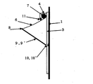
- FIG. 1 is an overall perspective view showing an embodiment of a solar shading device of the present invention.
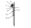
- FIG. 2 is a partially cutaway plan view showing an embodiment of the solar shading device of the present invention, with a portion omitted.
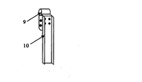
- FIG. 3 is an enlarged view showing a partially omitted torque hinge and an arm attached to the torque hinge, showing an embodiment of the solar shading device of the present invention.
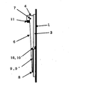
- FIG. 4 is a longitudinal plan view of an embodiment of the solar shading device according to the present invention in which a partially omitted arm rotates 180 degrees with respect to a wall surface.
- FIG. 5 is a partially omitted torque hinge showing an embodiment of the solar shading device of the present invention and an enlarged view when an arm is attached to the torque hinge.
- FIG. 1 is an overall perspective view showing an embodiment of a solar shading device of the present invention.
- FIG. 2 is a partially cutaway plan view showing an embodiment of the solar shading device of the present invention, with a portion omitted.
- FIG. 3 is an enlarged view showing a
- FIG. 6 is an enlarged view of the torque hinge when the partially omitted arm showing one embodiment of the solar shading device of the present invention does not rotate from the wall surface and when the arm is attached to the torque hinge.
- FIG. 7 is an enlarged view showing a torque hinge when the partially omitted arm showing an embodiment of the solar shading device of the present invention is rotated 180 degrees with respect to the wall surface and when the arm is attached to the torque hinge.
- the solar radiation shielding device of the present invention has an upper end portion of the roll screen 6 installed on the upper part of the window frame 3 on the outdoor side of the building by the biasing means. It is fixed to the winding shaft 7 urged in the winding direction, and the lower end portion of the roll screen 6 is pulled downward from the winding shaft 7 to shield the window from sunlight.
- the roll screen 6 is housed in a horizontally long roll screen case 4 having an opening for feeding on the lower surface, and roll screen case side plates 5 winding shafts 7 on both sides of the roll screen case 4 are rotatably installed.
- a biasing member such as a flat spring serving as a biasing means is fixed to both ends of the winding shaft 7 protruding, and the other end is fixed to the roll screen case side plate 5.
- the winding shaft 7 is urged in the winding direction by the urging member so that the roll screen 6 is always wound up.
- the roll screen 6 may be made of any material as long as it can block solar radiation and can be wound around the winding shaft 7. However, the roll screen 6 is in the form of a sheet having properties such as weather resistance, water resistance and flame resistance. Is preferably used. Further, the roll screen 6 may have a complete light shielding property or may transmit a part of visible light.
- the roll screen 6 it is also possible to use a photograph in which a building outer wall is photographed in advance and printed on a plain roll screen by a large format printer.
- the roll screens that have been put on the market or have been proposed so far are different from the exterior wall design of the building, so that the aesthetics of the exterior of the building are remarkably impaired, there is a sense of incongruity, and some people are even disgusting Although there is a solar shading effect, it is not generally adopted.
- the roll screen By using a roll screen on which the same pattern as the outer wall is printed, the roll screen can be integrated with the building, and the thermal environment of the house can be well maintained by the solar radiation shielding effect while maintaining the aesthetics of the building. It can be said that processing the roll screen used for the outer wall of the building as described above is a novel idea proposed for the first time by this specification.
- the roll screen 6 is brought into contact with a cleaning element 11 such as a brush at the time of winding and rewinding so as to remove dirt, so that the roll take-out entrance portion of the roll screen case 4 is removed.
- a cleaning element 11 such as a brush having a width slightly larger than the roll screen is fixed.
- the lower end portion of the roll screen 6 is supported by the support shaft 8.
- the support shaft 8 is composed of an aluminum extruded material and an end plastic cap, but the material of the support shaft may be iron, stainless steel, plastics, wood, or the like in addition to the aluminum extruded material.
- the cross-sectional shape of the support shaft member may be any of a circular shape, a rectangular shape, or a partially deformed shape as long as the lower end portion of the roll screen 6 is attached.
- One end of a pair of arms 9 and 9 ′ is connected to both ends of the support shaft 8 so that the pair of arms are arranged on a vertical surface in the axial direction of the support shaft.
- the support shaft member 8 and the arm 9 may be detachably connected by screws, bolts, rivets or the like, or may be integrally formed.
- the other ends of the pair of arms 9 and 9 ' are fixed to both sides of the outdoor window via torque hinges 10 and 10' that are hinge structures that enable the arms to be held at a desired rotation angle. ing.
- the torque hinge 10 which is a hinge device that can hold the arm at a desired rotation angle, is directly or via a metal fitting at an intermediate portion on both sides of the window on the outdoor side of the window frame 3. Is fixed.
- a gear motor can be used in addition to the torque hinge.
- the structure of the torque hinge 10 is not particularly limited as long as the operating force at the end of the arm can be in the above range, but among them, the friction type torque hinge is inexpensive and preferable.
- the other end of the arm 9 is connected to a torque hinge 10 that enables the arm to be held at a desired rotation angle.
- the arm 9 is formed of an aluminum extruded material having a U-shaped cross section, but the shape of the arm 9 may be L-shaped or pipe-shaped, and the material is iron, stainless steel, plastics, etc. Also good.
- the length of the arm 9 is preferably not more than the height of the window and not less than 1/3 of the height of the window.
- the arm has a structure in which the hinge part can be rotated from 0 degree to 180 degrees with respect to the central wall surface and held at a desired angle.
- the operation of the solar shading device for windows moves the support shaft 8 in the vertical direction below the take-up shaft, so that the arms 9 and 9 'have a hinge structure,
- the roll screen 6 that is rotated by an arc having a radius of the length of the arm 10 ′ as a fulcrum is held at a desired position so as to protrude outside the window.
- the operating force at the tips of the pair of arms 9 and 9 ′ due to the torque of the torque hinges 10 and 10 ′ located on both sides of the window is 1.1 times the winding force of the roll screen 6 by the biasing means. It is preferably 5 times, more preferably 1.1 to 2 times. If the operating force of the arm tip is less than 1.1 times the winding force of the roll screen 6 by the urging means, the roll screen 6 is wound even if a slight force is applied. If the operating force of the arm tip is larger than 5 times the winding force of the roll screen by the urging means, a large force is required to lower the lower end of the roll screen below the window. Further, when the roll screen receives wind, if the operating force is large, the roll screen can withstand a large wind pressure. However, since a large load is applied to the arm, a stronger arm is required.
- the winding force of the roll screen 6 by the urging means is constant regardless of the drawing length of the screen, it is relatively easy to set the torque value of the torque hinge, that is, the operating force of the arm tip within the above range. .
- the user can move the support shaft member 8 by directly pushing up the support shaft member 8 by hand. Attaching an operating rod or the like to the support shaft 8 so that it is possible to attach a string, a handle, etc. to the support shaft 8 or to move the support shaft 8 up and down easily from the room.
- the roll screen can be raised and lowered.
- the support shaft 8 at the lower end of the roll screen 6 accommodated in the roll screen case 4 is pulled down and stopped at a desired position, so that the holding position of the screen 6 can be operated very easily. it can.
- the roll screen 6 In the case of nighttime or absence, by moving the support shaft 8 downward, the angle between the arm and the wall surface is set to 180 °, the roll screen 6 is pulled down to the bottom, and the entire window can be covered.
- the roll screen 6 when the same pattern as an outer wall is printed on the roll screen 6, the roll screen 6 can be united with a building and the aesthetics of a building can be maintained.
- the roll screen 6 When the roll screen 6 receives wind pressure by the wind, the roll screen 6 is lifted by the wind pressure. At this time, the tension and the urging force generated in the roll screen 6 by the wind rather than the operating force at the ends of the arms 9 and 9 ′. Becomes larger, the arms 9 and 9 'rotate to pull the roll screen 6 upward. When the wind stops and the wind pressure on the roll screen disappears, the roll screen fabric is once slackened, but the slack roll screen is wound around the take-up shaft 7 by the biasing force caused by the biasing means. By repeating this several times, the roll screen 6 is wound up until the wind pressure is no longer applied by repeating the strength of the wind. For this reason, since a large load is not applied to the arms 9 and 9 ′, the arm 9 and 9 ′ can be used even with a small strength and can be manufactured at a low cost.
- the solar radiation shielding apparatus for windows according to the present invention has not only the solar radiation shielding function but also a function as a fence when it rains, and also has a function of preventing rain from entering even if the window is open.
- the present invention is not limited to the above-described embodiments, and various improvements and modifications can be made without departing from the spirit of the present invention. It is.
Abstract
Priority Applications (3)
| Application Number | Priority Date | Filing Date | Title |
|---|---|---|---|
| US14/776,784 US20160123017A1 (en) | 2014-01-27 | 2015-01-21 | Window sunlight-shielding device |
| EP15740840.2A EP3101196A4 (fr) | 2014-01-27 | 2015-01-21 | Dispositif pare-soleil pour fenêtres |
| CN201580000403.9A CN105229247A (zh) | 2014-01-27 | 2015-01-21 | 窗户的遮阳装置 |
Applications Claiming Priority (2)
| Application Number | Priority Date | Filing Date | Title |
|---|---|---|---|
| JP2014-012228 | 2014-01-27 | ||
| JP2014012228A JP5828598B2 (ja) | 2014-01-27 | 2014-01-27 | 窓の日射遮蔽装置 |
Publications (1)
| Publication Number | Publication Date |
|---|---|
| WO2015111590A1 true WO2015111590A1 (fr) | 2015-07-30 |
Family
ID=53681393
Family Applications (1)
| Application Number | Title | Priority Date | Filing Date |
|---|---|---|---|
| PCT/JP2015/051439 WO2015111590A1 (fr) | 2014-01-27 | 2015-01-21 | Dispositif pare-soleil pour fenêtres |
Country Status (5)
| Country | Link |
|---|---|
| US (1) | US20160123017A1 (fr) |
| EP (1) | EP3101196A4 (fr) |
| JP (1) | JP5828598B2 (fr) |
| CN (1) | CN105229247A (fr) |
| WO (1) | WO2015111590A1 (fr) |
Families Citing this family (7)
| Publication number | Priority date | Publication date | Assignee | Title |
|---|---|---|---|---|
| KR101707479B1 (ko) * | 2015-03-26 | 2017-02-27 | 윤병재 | 단열 창호 |
| WO2017048007A1 (fr) * | 2015-09-15 | 2017-03-23 | 김연태 | Auvent fonctionnel |
| CN109610581A (zh) * | 2019-01-24 | 2019-04-12 | 张利 | 一种基于互联网的移动智能公厕 |
| CN109914716B (zh) * | 2019-04-13 | 2020-10-09 | 浙江屹立建设有限公司 | 一种玻璃幕墙外遮阳装饰系统 |
| CN111894076A (zh) * | 2020-07-16 | 2020-11-06 | 东莞市建安集团有限公司 | 一种节能建筑用雨水收集系统 |
| TWI758163B (zh) * | 2021-02-08 | 2022-03-11 | 王泰興 | 逃生窗結構 |
| CN114991651B (zh) * | 2022-06-07 | 2024-01-09 | 伟大集团节能房股份有限公司 | 一种窗用太阳能遮阳装置 |
Citations (5)
| Publication number | Priority date | Publication date | Assignee | Title |
|---|---|---|---|---|
| JPS5629127U (fr) * | 1979-08-11 | 1981-03-19 | ||
| JPS608016Y2 (ja) * | 1981-11-14 | 1985-03-19 | 株式会社ヨコタ | 日除け |
| JP2005273314A (ja) | 2004-03-25 | 2005-10-06 | Nobuo Asai | 窓の日射遮蔽装置。 |
| JP2010150848A (ja) * | 2008-12-26 | 2010-07-08 | Kowa Co Ltd | 開閉装置用清掃装置及び開閉装置 |
| JP5123685B2 (ja) * | 2008-02-08 | 2013-01-23 | ミサワホーム株式会社 | 建物の軒先構造 |
Family Cites Families (19)
| Publication number | Priority date | Publication date | Assignee | Title |
|---|---|---|---|---|
| US1021330A (en) * | 1911-07-24 | 1912-03-26 | James E Ireland | Awning-arm. |
| US1719303A (en) * | 1926-02-23 | 1929-07-02 | Nels H Nelson | Awning |
| US1701793A (en) * | 1927-06-13 | 1929-02-12 | Nels H Nelson | Awning |
| US1750285A (en) * | 1927-07-16 | 1930-03-11 | Schuler George | Awning |
| US1779561A (en) * | 1929-10-31 | 1930-10-28 | Schuler George | Awning construction |
| US2050835A (en) * | 1932-10-26 | 1936-08-11 | Christian P Fogh | Awning |
| US2217067A (en) * | 1938-09-19 | 1940-10-08 | Clifford O Mccauley | Roller bracket |
| US2354832A (en) * | 1944-06-13 | 1944-08-01 | Ristine George | Adjustable bracket and brush for window shades |
| US3151664A (en) * | 1962-12-03 | 1964-10-06 | Disa Corp | Awning |
| US3722571A (en) * | 1970-09-21 | 1973-03-27 | Astrufs Co | Self-storing awning |
| DE2514941C3 (de) * | 1975-04-05 | 1984-06-20 | Clauss Markisen, 7311 Bissingen | Markise |
| NL7906793A (nl) * | 1979-09-12 | 1981-03-16 | Ezf Prod Nederland Bv | Zonnescherm. |
| DE3344359A1 (de) * | 1983-12-08 | 1985-06-20 | Clauss Markisen, 7311 Bissingen | Fenstermarkise |
| CN2381702Y (zh) * | 1999-07-08 | 2000-06-07 | 赵铁林 | 卷帘式门窗遮阳罩 |
| US6530123B1 (en) * | 2001-04-17 | 2003-03-11 | Reell Precision Manufacturing Corporation | Clip friction hinge with housing |
| US6843301B2 (en) * | 2002-09-09 | 2005-01-18 | Dometic Corporation | Awning roller with internal motor |
| DE102009011578B3 (de) * | 2009-03-06 | 2010-07-29 | Peter Losen | Rollladenbespannung |
| CN202227952U (zh) * | 2011-06-09 | 2012-05-23 | 格拉夫节能制品(南京)有限公司 | 外推型节能卷帘窗 |
| CN202578445U (zh) * | 2012-05-11 | 2012-12-05 | 河南维思能源环保技术有限公司 | 一种自动清洁式外遮阳卷帘窗 |
-
2014
- 2014-01-27 JP JP2014012228A patent/JP5828598B2/ja active Active
-
2015
- 2015-01-21 CN CN201580000403.9A patent/CN105229247A/zh active Pending
- 2015-01-21 WO PCT/JP2015/051439 patent/WO2015111590A1/fr active Application Filing
- 2015-01-21 US US14/776,784 patent/US20160123017A1/en not_active Abandoned
- 2015-01-21 EP EP15740840.2A patent/EP3101196A4/fr not_active Withdrawn
Patent Citations (5)
| Publication number | Priority date | Publication date | Assignee | Title |
|---|---|---|---|---|
| JPS5629127U (fr) * | 1979-08-11 | 1981-03-19 | ||
| JPS608016Y2 (ja) * | 1981-11-14 | 1985-03-19 | 株式会社ヨコタ | 日除け |
| JP2005273314A (ja) | 2004-03-25 | 2005-10-06 | Nobuo Asai | 窓の日射遮蔽装置。 |
| JP5123685B2 (ja) * | 2008-02-08 | 2013-01-23 | ミサワホーム株式会社 | 建物の軒先構造 |
| JP2010150848A (ja) * | 2008-12-26 | 2010-07-08 | Kowa Co Ltd | 開閉装置用清掃装置及び開閉装置 |
Non-Patent Citations (1)
| Title |
|---|
| See also references of EP3101196A4 * |
Also Published As
| Publication number | Publication date |
|---|---|
| JP5828598B2 (ja) | 2015-12-09 |
| EP3101196A1 (fr) | 2016-12-07 |
| JP2015140514A (ja) | 2015-08-03 |
| US20160123017A1 (en) | 2016-05-05 |
| EP3101196A4 (fr) | 2017-09-13 |
| CN105229247A (zh) | 2016-01-06 |
Similar Documents
| Publication | Publication Date | Title |
|---|---|---|
| JP5828598B2 (ja) | 窓の日射遮蔽装置 | |
| AU2012380094B2 (en) | Multifunctional integrated window | |
| US9359768B2 (en) | Adjustable all-season window awning/light shelf and operating mechanism therefor | |
| KR101823850B1 (ko) | 슬래트형 롤러 블라인드 | |
| JP2009506240A (ja) | 二重式可動ファサードシステム | |
| US20180135351A1 (en) | Window Shade | |
| KR101592403B1 (ko) | 블라인드가 내장된 창호 | |
| US20070034343A1 (en) | Window screen | |
| CN204851011U (zh) | 一种抗风外遮阳一体化窗 | |
| KR101765013B1 (ko) | 실외용 차양장치 | |
| KR101746553B1 (ko) | 공동주택용 발코니 차양장치 | |
| WO2017151064A1 (fr) | Store externe dans un logement vitré | |
| JP2008266934A (ja) | 折り畳み式雨戸 | |
| KR200446420Y1 (ko) | 베니션블라인드의 고정장치 | |
| JP5465096B2 (ja) | 電動日射遮蔽装置の太陽電池パネル取付装置 | |
| CN109707298B (zh) | 一种遮光窗 | |
| CN112431365A (zh) | 一种幕墙系统遮阳铝板眉头节能设计结构及其安装方法 | |
| CN205330484U (zh) | 一种抗强风外遮阳一体化窗 | |
| KR20160137165A (ko) | 블라인드 일체형 창문 | |
| KR101221573B1 (ko) | 망사 블라인드 | |
| JP5575402B2 (ja) | サッシ及びブラインド | |
| JP2013238012A (ja) | 外付けシェード | |
| CN201705173U (zh) | 外遮阳单摆百叶窗 | |
| KR20200143934A (ko) | 전동 롤 블라인드 | |
| JP2005273314A (ja) | 窓の日射遮蔽装置。 |
Legal Events
| Date | Code | Title | Description |
|---|---|---|---|
| WWE | Wipo information: entry into national phase |
Ref document number: 201580000403.9 Country of ref document: CN |
|
| 121 | Ep: the epo has been informed by wipo that ep was designated in this application |
Ref document number: 15740840 Country of ref document: EP Kind code of ref document: A1 |
|
| REEP | Request for entry into the european phase |
Ref document number: 2015740840 Country of ref document: EP |
|
| WWE | Wipo information: entry into national phase |
Ref document number: 2015740840 Country of ref document: EP |
|
| WWE | Wipo information: entry into national phase |
Ref document number: 14776784 Country of ref document: US |
|
| NENP | Non-entry into the national phase |
Ref country code: DE |