WO2015111477A1 - 車両用空調装置 - Google Patents
車両用空調装置 Download PDFInfo
- Publication number
- WO2015111477A1 WO2015111477A1 PCT/JP2015/050768 JP2015050768W WO2015111477A1 WO 2015111477 A1 WO2015111477 A1 WO 2015111477A1 JP 2015050768 W JP2015050768 W JP 2015050768W WO 2015111477 A1 WO2015111477 A1 WO 2015111477A1
- Authority
- WO
- WIPO (PCT)
- Prior art keywords
- motor
- carrier frequency
- heat generation
- inverter
- generation amount
- Prior art date
- Legal status (The legal status is an assumption and is not a legal conclusion. Google has not performed a legal analysis and makes no representation as to the accuracy of the status listed.)
- Ceased
Links
Images


Classifications
-
- B—PERFORMING OPERATIONS; TRANSPORTING
- B60—VEHICLES IN GENERAL
- B60L—PROPULSION OF ELECTRICALLY-PROPELLED VEHICLES; SUPPLYING ELECTRIC POWER FOR AUXILIARY EQUIPMENT OF ELECTRICALLY-PROPELLED VEHICLES; ELECTRODYNAMIC BRAKE SYSTEMS FOR VEHICLES IN GENERAL; MAGNETIC SUSPENSION OR LEVITATION FOR VEHICLES; MONITORING OPERATING VARIABLES OF ELECTRICALLY-PROPELLED VEHICLES; ELECTRIC SAFETY DEVICES FOR ELECTRICALLY-PROPELLED VEHICLES
- B60L58/00—Methods or circuit arrangements for monitoring or controlling batteries or fuel cells, specially adapted for electric vehicles
- B60L58/10—Methods or circuit arrangements for monitoring or controlling batteries or fuel cells, specially adapted for electric vehicles for monitoring or controlling batteries
- B60L58/12—Methods or circuit arrangements for monitoring or controlling batteries or fuel cells, specially adapted for electric vehicles for monitoring or controlling batteries responding to state of charge [SoC]
-
- B—PERFORMING OPERATIONS; TRANSPORTING
- B60—VEHICLES IN GENERAL
- B60H—ARRANGEMENTS OF HEATING, COOLING, VENTILATING OR OTHER AIR-TREATING DEVICES SPECIALLY ADAPTED FOR PASSENGER OR GOODS SPACES OF VEHICLES
- B60H1/00—Heating, cooling or ventilating devices
- B60H1/00357—Air-conditioning arrangements specially adapted for particular vehicles
- B60H1/00385—Air-conditioning arrangements specially adapted for particular vehicles for vehicles having an electrical drive, e.g. hybrid or fuel cell
- B60H1/00392—Air-conditioning arrangements specially adapted for particular vehicles for vehicles having an electrical drive, e.g. hybrid or fuel cell for electric vehicles having only electric drive means
-
- B—PERFORMING OPERATIONS; TRANSPORTING
- B60—VEHICLES IN GENERAL
- B60H—ARRANGEMENTS OF HEATING, COOLING, VENTILATING OR OTHER AIR-TREATING DEVICES SPECIALLY ADAPTED FOR PASSENGER OR GOODS SPACES OF VEHICLES
- B60H1/00—Heating, cooling or ventilating devices
- B60H1/00642—Control systems or circuits; Control members or indication devices for heating, cooling or ventilating devices
- B60H1/00735—Control systems or circuits characterised by their input, i.e. by the detection, measurement or calculation of particular conditions, e.g. signal treatment, dynamic models
- B60H1/00764—Control systems or circuits characterised by their input, i.e. by the detection, measurement or calculation of particular conditions, e.g. signal treatment, dynamic models the input being a vehicle driving condition, e.g. speed
-
- B—PERFORMING OPERATIONS; TRANSPORTING
- B60—VEHICLES IN GENERAL
- B60H—ARRANGEMENTS OF HEATING, COOLING, VENTILATING OR OTHER AIR-TREATING DEVICES SPECIALLY ADAPTED FOR PASSENGER OR GOODS SPACES OF VEHICLES
- B60H1/00—Heating, cooling or ventilating devices
- B60H1/02—Heating, cooling or ventilating devices the heat being derived from the propulsion plant
- B60H1/14—Heating, cooling or ventilating devices the heat being derived from the propulsion plant other than from cooling liquid of the plant
- B60H1/143—Heating, cooling or ventilating devices the heat being derived from the propulsion plant other than from cooling liquid of the plant the heat being derived from cooling an electric component, e.g. electric motors, electric circuits, fuel cells or batteries
-
- B—PERFORMING OPERATIONS; TRANSPORTING
- B60—VEHICLES IN GENERAL
- B60H—ARRANGEMENTS OF HEATING, COOLING, VENTILATING OR OTHER AIR-TREATING DEVICES SPECIALLY ADAPTED FOR PASSENGER OR GOODS SPACES OF VEHICLES
- B60H1/00—Heating, cooling or ventilating devices
- B60H1/22—Heating, cooling or ventilating devices the heat source being other than the propulsion plant
-
- B—PERFORMING OPERATIONS; TRANSPORTING
- B60—VEHICLES IN GENERAL
- B60L—PROPULSION OF ELECTRICALLY-PROPELLED VEHICLES; SUPPLYING ELECTRIC POWER FOR AUXILIARY EQUIPMENT OF ELECTRICALLY-PROPELLED VEHICLES; ELECTRODYNAMIC BRAKE SYSTEMS FOR VEHICLES IN GENERAL; MAGNETIC SUSPENSION OR LEVITATION FOR VEHICLES; MONITORING OPERATING VARIABLES OF ELECTRICALLY-PROPELLED VEHICLES; ELECTRIC SAFETY DEVICES FOR ELECTRICALLY-PROPELLED VEHICLES
- B60L1/00—Supplying electric power to auxiliary equipment of vehicles
- B60L1/003—Supplying electric power to auxiliary equipment of vehicles to auxiliary motors, e.g. for pumps, compressors
-
- B—PERFORMING OPERATIONS; TRANSPORTING
- B60—VEHICLES IN GENERAL
- B60L—PROPULSION OF ELECTRICALLY-PROPELLED VEHICLES; SUPPLYING ELECTRIC POWER FOR AUXILIARY EQUIPMENT OF ELECTRICALLY-PROPELLED VEHICLES; ELECTRODYNAMIC BRAKE SYSTEMS FOR VEHICLES IN GENERAL; MAGNETIC SUSPENSION OR LEVITATION FOR VEHICLES; MONITORING OPERATING VARIABLES OF ELECTRICALLY-PROPELLED VEHICLES; ELECTRIC SAFETY DEVICES FOR ELECTRICALLY-PROPELLED VEHICLES
- B60L15/00—Methods, circuits, or devices for controlling the traction-motor speed of electrically-propelled vehicles
- B60L15/20—Methods, circuits, or devices for controlling the traction-motor speed of electrically-propelled vehicles for control of the vehicle or its driving motor to achieve a desired performance, e.g. speed, torque, programmed variation of speed
-
- B—PERFORMING OPERATIONS; TRANSPORTING
- B60—VEHICLES IN GENERAL
- B60L—PROPULSION OF ELECTRICALLY-PROPELLED VEHICLES; SUPPLYING ELECTRIC POWER FOR AUXILIARY EQUIPMENT OF ELECTRICALLY-PROPELLED VEHICLES; ELECTRODYNAMIC BRAKE SYSTEMS FOR VEHICLES IN GENERAL; MAGNETIC SUSPENSION OR LEVITATION FOR VEHICLES; MONITORING OPERATING VARIABLES OF ELECTRICALLY-PROPELLED VEHICLES; ELECTRIC SAFETY DEVICES FOR ELECTRICALLY-PROPELLED VEHICLES
- B60L15/00—Methods, circuits, or devices for controlling the traction-motor speed of electrically-propelled vehicles
- B60L15/20—Methods, circuits, or devices for controlling the traction-motor speed of electrically-propelled vehicles for control of the vehicle or its driving motor to achieve a desired performance, e.g. speed, torque, programmed variation of speed
- B60L15/2009—Methods, circuits, or devices for controlling the traction-motor speed of electrically-propelled vehicles for control of the vehicle or its driving motor to achieve a desired performance, e.g. speed, torque, programmed variation of speed for braking
-
- B—PERFORMING OPERATIONS; TRANSPORTING
- B60—VEHICLES IN GENERAL
- B60L—PROPULSION OF ELECTRICALLY-PROPELLED VEHICLES; SUPPLYING ELECTRIC POWER FOR AUXILIARY EQUIPMENT OF ELECTRICALLY-PROPELLED VEHICLES; ELECTRODYNAMIC BRAKE SYSTEMS FOR VEHICLES IN GENERAL; MAGNETIC SUSPENSION OR LEVITATION FOR VEHICLES; MONITORING OPERATING VARIABLES OF ELECTRICALLY-PROPELLED VEHICLES; ELECTRIC SAFETY DEVICES FOR ELECTRICALLY-PROPELLED VEHICLES
- B60L3/00—Electric devices on electrically-propelled vehicles for safety purposes; Monitoring operating variables, e.g. speed, deceleration or energy consumption
- B60L3/0023—Detecting, eliminating, remedying or compensating for drive train abnormalities, e.g. failures within the drive train
- B60L3/003—Detecting, eliminating, remedying or compensating for drive train abnormalities, e.g. failures within the drive train relating to inverters
-
- B—PERFORMING OPERATIONS; TRANSPORTING
- B60—VEHICLES IN GENERAL
- B60L—PROPULSION OF ELECTRICALLY-PROPELLED VEHICLES; SUPPLYING ELECTRIC POWER FOR AUXILIARY EQUIPMENT OF ELECTRICALLY-PROPELLED VEHICLES; ELECTRODYNAMIC BRAKE SYSTEMS FOR VEHICLES IN GENERAL; MAGNETIC SUSPENSION OR LEVITATION FOR VEHICLES; MONITORING OPERATING VARIABLES OF ELECTRICALLY-PROPELLED VEHICLES; ELECTRIC SAFETY DEVICES FOR ELECTRICALLY-PROPELLED VEHICLES
- B60L3/00—Electric devices on electrically-propelled vehicles for safety purposes; Monitoring operating variables, e.g. speed, deceleration or energy consumption
- B60L3/0023—Detecting, eliminating, remedying or compensating for drive train abnormalities, e.g. failures within the drive train
- B60L3/0061—Detecting, eliminating, remedying or compensating for drive train abnormalities, e.g. failures within the drive train relating to electrical machines
-
- B—PERFORMING OPERATIONS; TRANSPORTING
- B60—VEHICLES IN GENERAL
- B60L—PROPULSION OF ELECTRICALLY-PROPELLED VEHICLES; SUPPLYING ELECTRIC POWER FOR AUXILIARY EQUIPMENT OF ELECTRICALLY-PROPELLED VEHICLES; ELECTRODYNAMIC BRAKE SYSTEMS FOR VEHICLES IN GENERAL; MAGNETIC SUSPENSION OR LEVITATION FOR VEHICLES; MONITORING OPERATING VARIABLES OF ELECTRICALLY-PROPELLED VEHICLES; ELECTRIC SAFETY DEVICES FOR ELECTRICALLY-PROPELLED VEHICLES
- B60L50/00—Electric propulsion with power supplied within the vehicle
- B60L50/50—Electric propulsion with power supplied within the vehicle using propulsion power supplied by batteries or fuel cells
- B60L50/51—Electric propulsion with power supplied within the vehicle using propulsion power supplied by batteries or fuel cells characterised by AC-motors
-
- B—PERFORMING OPERATIONS; TRANSPORTING
- B60—VEHICLES IN GENERAL
- B60L—PROPULSION OF ELECTRICALLY-PROPELLED VEHICLES; SUPPLYING ELECTRIC POWER FOR AUXILIARY EQUIPMENT OF ELECTRICALLY-PROPELLED VEHICLES; ELECTRODYNAMIC BRAKE SYSTEMS FOR VEHICLES IN GENERAL; MAGNETIC SUSPENSION OR LEVITATION FOR VEHICLES; MONITORING OPERATING VARIABLES OF ELECTRICALLY-PROPELLED VEHICLES; ELECTRIC SAFETY DEVICES FOR ELECTRICALLY-PROPELLED VEHICLES
- B60L7/00—Electrodynamic brake systems for vehicles in general
- B60L7/10—Dynamic electric regenerative braking
- B60L7/14—Dynamic electric regenerative braking for vehicles propelled by AC motors
-
- B—PERFORMING OPERATIONS; TRANSPORTING
- B60—VEHICLES IN GENERAL
- B60H—ARRANGEMENTS OF HEATING, COOLING, VENTILATING OR OTHER AIR-TREATING DEVICES SPECIALLY ADAPTED FOR PASSENGER OR GOODS SPACES OF VEHICLES
- B60H1/00—Heating, cooling or ventilating devices
- B60H1/00271—HVAC devices specially adapted for particular vehicle parts or components and being connected to the vehicle HVAC unit
- B60H2001/00307—Component temperature regulation using a liquid flow
-
- B—PERFORMING OPERATIONS; TRANSPORTING
- B60—VEHICLES IN GENERAL
- B60H—ARRANGEMENTS OF HEATING, COOLING, VENTILATING OR OTHER AIR-TREATING DEVICES SPECIALLY ADAPTED FOR PASSENGER OR GOODS SPACES OF VEHICLES
- B60H1/00—Heating, cooling or ventilating devices
- B60H1/22—Heating, cooling or ventilating devices the heat source being other than the propulsion plant
- B60H2001/2228—Heating, cooling or ventilating devices the heat source being other than the propulsion plant controlling the operation of heaters
- B60H2001/224—Heating, cooling or ventilating devices the heat source being other than the propulsion plant controlling the operation of heaters automatic operation, e.g. control circuits or methods
-
- B—PERFORMING OPERATIONS; TRANSPORTING
- B60—VEHICLES IN GENERAL
- B60K—ARRANGEMENT OR MOUNTING OF PROPULSION UNITS OR OF TRANSMISSIONS IN VEHICLES; ARRANGEMENT OR MOUNTING OF PLURAL DIVERSE PRIME-MOVERS IN VEHICLES; AUXILIARY DRIVES FOR VEHICLES; INSTRUMENTATION OR DASHBOARDS FOR VEHICLES; ARRANGEMENTS IN CONNECTION WITH COOLING, AIR INTAKE, GAS EXHAUST OR FUEL SUPPLY OF PROPULSION UNITS IN VEHICLES
- B60K11/00—Arrangement in connection with cooling of propulsion units
- B60K11/02—Arrangement in connection with cooling of propulsion units with liquid cooling
-
- B—PERFORMING OPERATIONS; TRANSPORTING
- B60—VEHICLES IN GENERAL
- B60K—ARRANGEMENT OR MOUNTING OF PROPULSION UNITS OR OF TRANSMISSIONS IN VEHICLES; ARRANGEMENT OR MOUNTING OF PLURAL DIVERSE PRIME-MOVERS IN VEHICLES; AUXILIARY DRIVES FOR VEHICLES; INSTRUMENTATION OR DASHBOARDS FOR VEHICLES; ARRANGEMENTS IN CONNECTION WITH COOLING, AIR INTAKE, GAS EXHAUST OR FUEL SUPPLY OF PROPULSION UNITS IN VEHICLES
- B60K1/00—Arrangement or mounting of electrical propulsion units
- B60K2001/003—Arrangement or mounting of electrical propulsion units with means for cooling the electrical propulsion units
-
- B—PERFORMING OPERATIONS; TRANSPORTING
- B60—VEHICLES IN GENERAL
- B60K—ARRANGEMENT OR MOUNTING OF PROPULSION UNITS OR OF TRANSMISSIONS IN VEHICLES; ARRANGEMENT OR MOUNTING OF PLURAL DIVERSE PRIME-MOVERS IN VEHICLES; AUXILIARY DRIVES FOR VEHICLES; INSTRUMENTATION OR DASHBOARDS FOR VEHICLES; ARRANGEMENTS IN CONNECTION WITH COOLING, AIR INTAKE, GAS EXHAUST OR FUEL SUPPLY OF PROPULSION UNITS IN VEHICLES
- B60K1/00—Arrangement or mounting of electrical propulsion units
- B60K2001/003—Arrangement or mounting of electrical propulsion units with means for cooling the electrical propulsion units
- B60K2001/006—Arrangement or mounting of electrical propulsion units with means for cooling the electrical propulsion units the electric motors
-
- B—PERFORMING OPERATIONS; TRANSPORTING
- B60—VEHICLES IN GENERAL
- B60L—PROPULSION OF ELECTRICALLY-PROPELLED VEHICLES; SUPPLYING ELECTRIC POWER FOR AUXILIARY EQUIPMENT OF ELECTRICALLY-PROPELLED VEHICLES; ELECTRODYNAMIC BRAKE SYSTEMS FOR VEHICLES IN GENERAL; MAGNETIC SUSPENSION OR LEVITATION FOR VEHICLES; MONITORING OPERATING VARIABLES OF ELECTRICALLY-PROPELLED VEHICLES; ELECTRIC SAFETY DEVICES FOR ELECTRICALLY-PROPELLED VEHICLES
- B60L2240/00—Control parameters of input or output; Target parameters
- B60L2240/10—Vehicle control parameters
- B60L2240/12—Speed
-
- B—PERFORMING OPERATIONS; TRANSPORTING
- B60—VEHICLES IN GENERAL
- B60L—PROPULSION OF ELECTRICALLY-PROPELLED VEHICLES; SUPPLYING ELECTRIC POWER FOR AUXILIARY EQUIPMENT OF ELECTRICALLY-PROPELLED VEHICLES; ELECTRODYNAMIC BRAKE SYSTEMS FOR VEHICLES IN GENERAL; MAGNETIC SUSPENSION OR LEVITATION FOR VEHICLES; MONITORING OPERATING VARIABLES OF ELECTRICALLY-PROPELLED VEHICLES; ELECTRIC SAFETY DEVICES FOR ELECTRICALLY-PROPELLED VEHICLES
- B60L2240/00—Control parameters of input or output; Target parameters
- B60L2240/10—Vehicle control parameters
- B60L2240/34—Cabin temperature
-
- B—PERFORMING OPERATIONS; TRANSPORTING
- B60—VEHICLES IN GENERAL
- B60L—PROPULSION OF ELECTRICALLY-PROPELLED VEHICLES; SUPPLYING ELECTRIC POWER FOR AUXILIARY EQUIPMENT OF ELECTRICALLY-PROPELLED VEHICLES; ELECTRODYNAMIC BRAKE SYSTEMS FOR VEHICLES IN GENERAL; MAGNETIC SUSPENSION OR LEVITATION FOR VEHICLES; MONITORING OPERATING VARIABLES OF ELECTRICALLY-PROPELLED VEHICLES; ELECTRIC SAFETY DEVICES FOR ELECTRICALLY-PROPELLED VEHICLES
- B60L2240/00—Control parameters of input or output; Target parameters
- B60L2240/10—Vehicle control parameters
- B60L2240/36—Temperature of vehicle components or parts
-
- B—PERFORMING OPERATIONS; TRANSPORTING
- B60—VEHICLES IN GENERAL
- B60L—PROPULSION OF ELECTRICALLY-PROPELLED VEHICLES; SUPPLYING ELECTRIC POWER FOR AUXILIARY EQUIPMENT OF ELECTRICALLY-PROPELLED VEHICLES; ELECTRODYNAMIC BRAKE SYSTEMS FOR VEHICLES IN GENERAL; MAGNETIC SUSPENSION OR LEVITATION FOR VEHICLES; MONITORING OPERATING VARIABLES OF ELECTRICALLY-PROPELLED VEHICLES; ELECTRIC SAFETY DEVICES FOR ELECTRICALLY-PROPELLED VEHICLES
- B60L2240/00—Control parameters of input or output; Target parameters
- B60L2240/40—Drive Train control parameters
- B60L2240/42—Drive Train control parameters related to electric machines
- B60L2240/421—Speed
-
- B—PERFORMING OPERATIONS; TRANSPORTING
- B60—VEHICLES IN GENERAL
- B60L—PROPULSION OF ELECTRICALLY-PROPELLED VEHICLES; SUPPLYING ELECTRIC POWER FOR AUXILIARY EQUIPMENT OF ELECTRICALLY-PROPELLED VEHICLES; ELECTRODYNAMIC BRAKE SYSTEMS FOR VEHICLES IN GENERAL; MAGNETIC SUSPENSION OR LEVITATION FOR VEHICLES; MONITORING OPERATING VARIABLES OF ELECTRICALLY-PROPELLED VEHICLES; ELECTRIC SAFETY DEVICES FOR ELECTRICALLY-PROPELLED VEHICLES
- B60L2240/00—Control parameters of input or output; Target parameters
- B60L2240/40—Drive Train control parameters
- B60L2240/42—Drive Train control parameters related to electric machines
- B60L2240/423—Torque
-
- Y—GENERAL TAGGING OF NEW TECHNOLOGICAL DEVELOPMENTS; GENERAL TAGGING OF CROSS-SECTIONAL TECHNOLOGIES SPANNING OVER SEVERAL SECTIONS OF THE IPC; TECHNICAL SUBJECTS COVERED BY FORMER USPC CROSS-REFERENCE ART COLLECTIONS [XRACs] AND DIGESTS
- Y02—TECHNOLOGIES OR APPLICATIONS FOR MITIGATION OR ADAPTATION AGAINST CLIMATE CHANGE
- Y02T—CLIMATE CHANGE MITIGATION TECHNOLOGIES RELATED TO TRANSPORTATION
- Y02T10/00—Road transport of goods or passengers
- Y02T10/60—Other road transportation technologies with climate change mitigation effect
- Y02T10/64—Electric machine technologies in electromobility
-
- Y—GENERAL TAGGING OF NEW TECHNOLOGICAL DEVELOPMENTS; GENERAL TAGGING OF CROSS-SECTIONAL TECHNOLOGIES SPANNING OVER SEVERAL SECTIONS OF THE IPC; TECHNICAL SUBJECTS COVERED BY FORMER USPC CROSS-REFERENCE ART COLLECTIONS [XRACs] AND DIGESTS
- Y02—TECHNOLOGIES OR APPLICATIONS FOR MITIGATION OR ADAPTATION AGAINST CLIMATE CHANGE
- Y02T—CLIMATE CHANGE MITIGATION TECHNOLOGIES RELATED TO TRANSPORTATION
- Y02T10/00—Road transport of goods or passengers
- Y02T10/60—Other road transportation technologies with climate change mitigation effect
- Y02T10/70—Energy storage systems for electromobility, e.g. batteries
-
- Y—GENERAL TAGGING OF NEW TECHNOLOGICAL DEVELOPMENTS; GENERAL TAGGING OF CROSS-SECTIONAL TECHNOLOGIES SPANNING OVER SEVERAL SECTIONS OF THE IPC; TECHNICAL SUBJECTS COVERED BY FORMER USPC CROSS-REFERENCE ART COLLECTIONS [XRACs] AND DIGESTS
- Y02—TECHNOLOGIES OR APPLICATIONS FOR MITIGATION OR ADAPTATION AGAINST CLIMATE CHANGE
- Y02T—CLIMATE CHANGE MITIGATION TECHNOLOGIES RELATED TO TRANSPORTATION
- Y02T10/00—Road transport of goods or passengers
- Y02T10/60—Other road transportation technologies with climate change mitigation effect
- Y02T10/72—Electric energy management in electromobility
Definitions
- the present invention relates to a vehicle air conditioner that air-conditions a vehicle interior space, and more particularly to a vehicle air conditioner that includes a motor as a drive source.
- the inverter converts the DC power of the battery into AC power and supplies it to the motor.
- the motor output is controlled by changing the carrier frequency of the inverter when converting power.
- the carrier frequency of the inverter is not uniquely determined for the motor output. For example, when the target output of the motor is set according to the traveling state of the vehicle, there are a plurality of carrier frequencies that can realize the target output. Conventionally, power conversion is usually performed at a carrier frequency that is as good as possible in motor efficiency (that is, as small as possible in motor loss), depending on the conditions to be used.
- Patent Document 1 in a vehicle equipped with a motor as a drive source, torque reduction can be performed by temporarily increasing the carrier frequency during gear shifting to increase motor loss and lower motor efficiency. It is disclosed.
- a vehicle equipped with a motor as a drive source tends to lack a heat source for vehicle interior heating, for example, compared with a vehicle equipped with only an internal combustion engine.
- an electric heater or the like is added to an air conditioner for air conditioning a vehicle interior space. May be.
- the addition of such an electric heater causes an increase in vehicle weight, vehicle cost, and power consumption.
- the present invention addresses the above-described problem in a vehicle air conditioner equipped with a motor as a drive source, and an object thereof is to provide a vehicle air conditioner that can secure a heat source for vehicle interior heating without adding an electric heater or the like. To do.
- the present invention provides an air conditioner used in a vehicle including a motor as a drive source and an inverter that controls the output of the motor by changing the carrier frequency.
- a heater core that is arranged on a refrigerant circulation path that cools at least one of the inverters and that heats the conditioned air by using the refrigerant as a heat source, and a necessary heat generation amount of the motor and the inverter according to the vehicle interior temperature required by the occupant
- the carrier frequency setting means for setting the carrier frequency for the required heat generation amount and the carrier frequency setting means And converted into AC power DC power of the power storage device at a carrier frequency which is characterized by having a power converter for supplying to the motor.
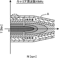
- FIG. 4 is a diagram showing heat generation characteristics of a motor and an inverter when the carrier frequency of the inverter provided in the vehicle is 10 kHz, overlaid on the operation region of the motor. It is a figure which similarly shows the heat_generation
- FIG. 1 is a block diagram showing a mechanical configuration of a vehicle air conditioner 10 according to the present embodiment.
- upstream and downstream refer to the air flow in the air conditioner 10 unless otherwise specified.
- the air conditioner 10 is mounted on an electric vehicle including only the motor 20 (see FIG. 2) without including an internal combustion engine as a drive source.
- the air conditioner 10 is arrange
- the air conditioner 10 includes an outside air introduction passage 11 a for introducing air (outside air) in the vehicle exterior space into the air conditioner 10, and an inside air introduction passage 11 b for introducing air in the vehicle interior space (inside air) into the air conditioner 10.
- a main duct passage 11c is connected to the downstream ends of the outside air introduction passage 11a and the inside air introduction passage 11b, and a cooling passage 11d and a heating passage 11e are connected to the downstream ends of the main duct passage 11c, and the cooling passage 11d and the heating passage An outlet passage 11f is connected to the downstream end of 11e.
- a plurality of air outlets 11g are provided at the downstream end of the air outlet passage 11f to blow out air (air conditioned air) cooled, heated, or dehumidified by the air conditioner 10 into the vehicle interior space.
- air outlet 11g a vent air outlet that blows air conditioned air toward the upper body of the front seat occupant, a heat air outlet that blows air conditioned air toward the feet of the front seat occupant, and an inner surface of a front windshield (not shown)
- a defroster outlet that blows conditioned air from below to above, a rear vent outlet that blows conditioned air toward the upper body of the passenger in the rear seat, and a rear heat outlet that blows conditioned air toward the feet of the passenger in the rear seat Is provided.
- a blower fan 12 and an evaporator 13 are arranged from the upstream side.
- a heater core 14 is disposed in the heating passage 11e.
- An inside / outside air switching damper 15 is disposed at the downstream end of the outside air introduction passage 11a and the inside air introduction passage 11b.
- the inside / outside air switching damper 15 is configured to be located at an arbitrary position between a position where the outside air introduction passage 11a is closed (inside air circulation position) and a position where the inside air introduction passage 11b is closed (outside air introduction position). .
- the ratio of the opening degree of the outside air introduction passage 11a and the inside air introduction passage 11b is adjusted, and the mixing ratio of the outside air and the inside air of the conditioned air blown from the air outlet 11g is variously adjusted.
- the blower fan 12 is disposed downstream of the inside / outside air switching damper 15 and is driven to generate conditioned air flowing from the outside air introduction passage 11a and the inside air introduction passage 11b toward the outlet 11g.
- the evaporator 13 is a heat exchanger for cooling, and is disposed downstream of the blower fan 12 to cool the conditioned air.
- a temperature control damper 16 is disposed at the upstream end of the cooling passage 11d and the heating passage 11e.
- the temperature control damper 16 is configured to be located at an arbitrary position between a position for closing the cooling passage 11d (heating position) and a position for closing the heating passage 11e (cooling position). Thereby, the ratio of the opening degree of the passage 11d for cooling and the passage 11e for heating is adjusted, and the temperature of the conditioned air blown from the outlet 11g is variously adjusted.
- the heater core 14 is a heat exchanger for heating and is arranged downstream of the temperature control damper 16 to heat the conditioned air.
- cooling water of the motor 20 and the inverter 30 that can be used as a heat source for heating the vehicle passes through the heater core 14.
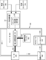
- FIG. 2 is a block diagram showing a system configuration of an electric vehicle on which the vehicle air conditioner 10 is mounted.
- the air conditioner 10 is displayed as “HVAC”, which is an abbreviation of “Heating, Ventilation and Air Conditioning”.
- the electric vehicle includes a motor 20, an inverter 30 that controls the output of the motor 20 by changing the carrier frequency, and a cooling water circulation path 50 that cools the motor 20 and the inverter 30. .
- the motor 20, the inverter 30, the electric pump 40, and the heater core 14 of the air conditioner 10 are arranged on the cooling water circulation path 50.
- the cooling water circulates in the order of the inverter 30 ⁇ the motor 20 ⁇ the electric pump 40 ⁇ the heater core 14 ⁇ the inverter 30.
- a radiator that radiates heat of the cooling water may be interposed between the heater core 14 and the inverter 30.
- the cooling water takes heat from these when passing through the inverter 30 and the motor 20 and is used as a heat source when the heater core 14 heats the conditioned air when passing through the heater core 14.
- the inverter 30 includes an inverter control device 31 and a power converter 33, and the inverter control device 31 includes a carrier frequency changing unit 32.
- the set target output is output to the inverter control device 31 together with a target vehicle speed, a deceleration regeneration instruction, and the like.
- the air-conditioning controller 70 is a vehicle interior temperature required by the occupant, an inside / outside temperature introduced into the air-conditioning apparatus 10, a temperature of cooling water circulating in the cooling water circulation path 50, a flow rate of air-conditioning air generated by driving the blower fan 12, etc. Accordingly, the necessary heat generation amount of the motor 20 and the inverter 30 is set and output to the inverter control device 31.
- the air conditioning controller 70 corresponds to the necessary heat generation setting means of the present invention.
- the inverter control device 31, the vehicle controller 60, and the air conditioning controller 70 are each a well-known microprocessor including a CPU, a ROM, a RAM, and the like.
- the carrier frequency changing unit 32 of the inverter control device 31 needs to set the heat generation amount of the motor 20 and the inverter 30 by the air conditioning controller 70 among the carrier frequencies that can realize the target output of the motor 20 set by the vehicle controller 60.
- a carrier frequency that is a calorific value is set and output to the power converter 33.
- the carrier frequency changing unit 32 corresponds to the carrier frequency setting means of the present invention.
- the power conversion device 33 converts the direct current power (DC) of the drive power supply battery 90 (corresponding to the power storage device of the present invention) into alternating current power (AC) at the carrier frequency set by the carrier frequency changing unit 32 and converts it into the motor 20. Supply.
- the power conversion device 33 corresponds to the power conversion means of the present invention.
- the motor 20 functions as a regenerative alternator (generator) during deceleration.
- the power conversion device 33 converts the AC power generated by the motor 20 into DC power and supplies it to the drive power supply battery 90.
- the carrier frequency is a period of a timer that operates at a constant period in order to turn on / off a pulse signal in a pulse modulation (PWM) system.
- the pulse width is controlled by giving this timer a position to turn on the pulse signal.
- FIG. 3 and 4 are diagrams showing the heat generation characteristics of the motor 20 and the inverter 30 when the carrier frequency of the inverter 30 is 10 kHz and 5 kHz, superimposed on the operation region of the motor 20.
- Such heat generation characteristics are experimentally created in advance and stored in the inverter control device 31.
- the region surrounded by the speed torque curve A (NT characteristic) indicating the relationship between the rotational speed (also referred to as speed) N of the motor 20 and the torque T is the operating region of the motor 20.
- the speed torque curve A indicates the maximum torque of the motor 20 at that speed, and the motor 20 can be operated in the entire region surrounded by the speed torque curve A.
- the motor 20 has a constant torque characteristic in which the torque T is constant even when the speed changes in the low speed range, and has a constant output characteristic in which the torque T decreases as the speed increases in the middle to high speed range.
- the region above zero (0) on the vertical axis is a region when the motor 20 is running, and the region below zero is a region during deceleration regeneration. In any case, the amount of heat generation increases as the absolute value of the torque T increases. 3 and 4, the same hatching pattern represents the same calorific value.
- the vehicle controller 60 sets a low-speed / medium-torque region surrounded by a broken-line circle as a target output of the motor 20 (starting, climbing, etc.).
- This low-speed / medium torque region can be realized regardless of whether the carrier frequency is 10 kHz or 5 kHz.
- the carrier frequency is 10 kHz
- the amount of heat generated by the motor 20 and the inverter 30 is larger than when the carrier frequency is 5 kHz. That is, the motor efficiency is low (the loss of the motor 20 is large).
- the carrier frequency changing unit 32 controls the carrier frequency to 5 kHz, which has a smaller calorific value.
- the carrier frequency changing unit 32 and the power conversion device 33 use the motor among the carrier frequencies that can realize the target output of the motor 20. Power is not converted at an efficient carrier frequency (5 kHz in the example) as much as possible, but at a carrier frequency (10 kHz in the example) that can realize the necessary heat generation amount set by the air conditioning controller 70 according to the passenger's request. Perform conversion.
- the heat generation of the motor 20 and the inverter 30 is positively performed by using a carrier frequency with low efficiency (a large loss and heat generation) without performing the control with the highest priority on efficiency as in the prior art. Control.
- the required heat generation amount based on the air conditioning requirement happened to be equal to the maximum heat generation amount of the motor 20 and the inverter 30, so 10 kHz was selected as the carrier frequency.
- the necessary heat generation amount is higher than the maximum heat generation amount. If it is smaller, a carrier frequency smaller than 10 kHz will be selected.
- the heat generation can be controlled by changing the carrier frequency.
- the carrier frequency By changing the carrier frequency, the output of the motor 20 is controlled, and the amount of heat generated by the motor 20 and the inverter 30 is controlled.
- the heat generation amount of the motor 20 and the inverter 30 basically depends only on the carrier frequency. Therefore, the heat generation amount can be predicted with high accuracy, and the necessary heat generation amount can be accurately determined. Can be realized.
- the carrier frequency changing unit 32 sets the target of the motor 20 regardless of the required heat generation amount set by the air conditioning controller 70 until a predetermined time (for example, 5 minutes) elapses after the operation of the motor 20 starts.
- a carrier frequency (10 kHz in the example) at which the heat generation amount of the motor 20 and the inverter 30 is maximized is set among the carrier frequencies that can realize the output.
- the carrier frequency that maximizes the heat generation amount of the motor 20 and the inverter 30 is set until a predetermined time elapses after the operation of the motor 20 is started, so that the motor 20 that requires rapid heating of the cooling water is set.
- the temperature of the cooling water can be raised as soon as possible after the start of operation, ensuring an early heat source for heating the interior of the vehicle, and optimal air conditioning with good responsiveness to passenger heating requirements from the beginning after the vehicle starts running A state can be realized.
- the carrier frequency may be lowered to reduce the heat generation amount of the motor 20 and the inverter 30 to return to the efficiency-oriented running.
- the predetermined time is, for example, the time required for the temperature of the cooling water to rise to a temperature that can be used for air conditioning (for example, 40 to 50 ° C.).
- the carrier frequency is increased again while maintaining the target output of the motor 20. Then, the heat generation amount of the motor 20 and the inverter 30 is increased to reheat the cooling water.
- the inverter control device 31 transmits to the air conditioning controller 70 that 80% of the required heat generation amount can be secured, for example, and the air conditioning controller 70 that has received this transmits, for example, the conditioned air generated by driving the blower fan 12
- the temperature of the conditioned air blown from the air outlet 11g is maintained at the vehicle interior temperature required by the occupant by reducing the flow rate or the like.
- the inverter control device 31 corresponds to the heat generation amount setting means that can be secured according to the present invention
- the air conditioning controller 70 corresponds to the air conditioning air flow rate restricting means according to the present invention.
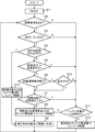
- FIG. 5 is a flowchart showing an example of the control operation of the electric vehicle according to the present embodiment.
- step S1 after the power conversion device 33 is in a READY state (a state where work can be started), the inverter control device 31 determines whether or not there is a heating request from the air conditioning controller 70 in step S2. If YES, the process proceeds to step S3. If NO, the process proceeds to step S11.
- step S3 the vehicle controller 60 determines whether or not the vehicle is running. If YES, the process proceeds to step S4. If NO, the process proceeds to step S11.
- step S4 the inverter control device 31 determines whether it is within 5 minutes after the start of traveling. In the case of YES (initial after the vehicle starts to travel), the process proceeds to step S13, and in the case of NO (after the middle period after the vehicle starts to travel), the process proceeds to step S5.
- step S5 the vehicle controller 60 determines whether the vehicle is traveling uphill or traveling at high speed. This determination can be made based on the operation region of the motor 20 shown in FIGS. 3 and 4, for example. For example, when the target output of the motor 20 is set in the low speed / medium torque region, it is determined that the vehicle is traveling uphill, and when the motor 20 is set in the high speed / low torque region, the vehicle travels at high speed.
- step S6 the inverter control device 31 determines whether or not it is in an acceleration / deceleration limited state. That is, it is determined whether or not the output of the motor 20 is restricted from being controlled by the inverter 30 by changing the carrier frequency. If YES, the process proceeds to step S10. If NO, the process proceeds to step S7.
- step S10 the vehicle controller 60 determines whether deceleration regeneration is in progress. If YES, the process proceeds to step S7. If NO, the process proceeds to step S11. Here, in the case of YES, the process proceeds to step S7 because, as described above, the motor 20 and the inverter 30 generate heat during deceleration regeneration, and the amount of generated heat can be positively controlled.
- step S7 the air conditioning controller 70 determines whether or not the heat source temperature (cooling water temperature or heater core 14 temperature) is equal to or higher than a reference value (temperature that can be used for air conditioning (for example, 40 to 50 ° C.)). If YES, the process proceeds to step S11. If NO, the process proceeds to step S8.
- a reference value temperature that can be used for air conditioning
- step S8 the carrier frequency changing unit 32 and the power conversion device 33 perform inverter control, that is, power conversion at a carrier frequency that promotes heat generation. Specifically, power conversion is performed at a carrier frequency at which the heat generation amount of the motor 20 and the inverter 30 becomes the necessary heat generation amount set by the air conditioning controller 70 among the carrier frequencies that can achieve the target output of the motor 20.
- the heat generation amount of the motor 20 and the inverter 30 is positively controlled by using a carrier frequency with low efficiency (loss and large heat generation amount).
- step S9 the heat generated by the motor 20 and the inverter 30 is used for air conditioning via the cooling water.
- step S4 when it is determined YES in step S4 and the process proceeds to step S13, the carrier frequency changing unit 32 and the power conversion device 33 perform inverter control, that is, power conversion at the carrier frequency that promotes heat generation.
- inverter control that is, power conversion at the carrier frequency that promotes heat generation.
- power conversion is performed at a carrier frequency at which the heat generation amount of the motor 20 and the inverter 30 is maximum among the carrier frequencies that can realize the target output of the motor 20. Is called.
- the heat generation amount of the motor 20 and the inverter 30 is positively controlled by using a carrier frequency with low efficiency (loss and large heat generation amount).
- step S9 the heat generated by the motor 20 and the inverter 30 is used for air conditioning via the cooling water.
- step S11 the inverter control device 31 determines whether or not the state of charge (SOC) of the drive power supply battery 90 is a full charge (Full) state. If YES, the process proceeds to step S8. If NO, the process proceeds to step S12. Here, in the case of YES, the process proceeds to step S8 because the charged state of the battery 90 does not become excessively low even if the motor 20 travels with low efficiency. In this case, the inverter control device 31 corresponds to the determination unit of the present invention.
- SOC state of charge
- Full full charge
- step S12 the carrier frequency changing unit 32 and the power conversion device 33 perform inverter control, that is, power conversion at a highly efficient carrier frequency. This realizes efficiency-oriented traveling with low power consumption, and saves the power of the battery 90 as much as possible.
- the carrier frequency changing unit 32 and the power conversion device 33 correspond to execution means of the present invention.
- the following characteristic configuration is employed in the air conditioner 10 for an electric vehicle that includes only the motor 20 as a drive source.
- a heater core 14 that heats the conditioned air using the cooling water as a heat source is disposed on the cooling water circulation path 50 that cools both the motor 20 and the inverter 30 that controls the output of the motor 20 by changing the carrier frequency. It is installed.
- the air conditioning controller 70 sets the necessary heat generation amount of the motor 20 and the inverter 30 according to the passenger compartment temperature required by the passenger.
- the carrier frequency changing unit 32 uses the air conditioning controller 70 to generate heat generated by the motor 20 and the inverter 30 among the carrier frequencies that can achieve the target output of the motor 20 set by the vehicle controller 60 according to the running state of the vehicle. Set the carrier frequency for the required heat generation amount.
- the power converter 33 converts the DC power of the drive power source battery 90 into AC power at the carrier frequency set by the carrier frequency changing unit 32 and supplies the AC power to the motor 20.
- the air conditioner 10 for an electric vehicle that includes only the motor 20 as a driving source and tends to lack a heat source for vehicle interior heating, circulation of cooling water that cools both the motor 20 and the inverter 30. Since the heater core 14 is disposed on the path 50, the heat generated by the motor 20 and the inverter 30 is used for heating the conditioned air. Therefore, for example, a vehicle air conditioner 10 that can secure a heat source for vehicle interior heating without adding an electric heater such as a PTC heater is provided.
- the necessary heat generation amount of the motor 20 and the inverter 30 is set by the air conditioning controller 70 according to the passenger compartment temperature requested by the occupant, and the motor 20 set by the carrier frequency changing unit 32 according to the traveling state of the vehicle. Since the carrier frequency at which the heat generation amount of the motor 20 and the inverter 30 becomes the above required heat generation amount among the carrier frequencies that can realize the target output is set, and power conversion is performed at the set carrier frequency by the power conversion device 33. While maintaining the target output of the motor 20, the passenger compartment temperature required by the occupant can be accurately realized without excess or deficiency.
- the carrier frequency at which the heat generation amount of the motor 20 and the inverter 30 becomes the necessary heat generation amount is set.
- the carrier frequency is set from the viewpoint of the heat generation amount of the motor 20 and the inverter 30, so Compared with the case where the frequency is set from the viewpoint of emphasizing efficiency, the heat generation amount of the motor 20 and the inverter 30 can be easily set to the necessary heat generation amount.
- the heat generation amount of the motor 20 and the inverter 30 basically depends only on the carrier frequency, the heat generation amount can be predicted with high accuracy, and the necessary heat generation amount can be realized with high accuracy.
- the carrier frequency changing unit 32 takes a time (for example, a time required for the temperature of the cooling water to rise to a temperature that can be used for air conditioning (for example, 40 to 50 ° C.) after the operation of the motor 20 starts. (E.g., 5 minutes)) (e.g., YES in step S4), the motor 20 out of the carrier frequency capable of realizing the target output of the motor 20 regardless of the necessary heat generation amount set by the air conditioning controller 70.
- a carrier frequency at which the amount of heat generated by the inverter 30 is maximized is set (step S13).
- the temperature of the cooling water can be increased as soon as possible after the start of operation of the motor 20 that requires rapid heating of the cooling water, and a heat source for vehicle interior heating can be secured early.
- a heat source for vehicle interior heating can be secured early.
- the inverter control device 31 sets a heat generation amount that can be ensured.
- the flow rate of the conditioned air is reduced so that the temperature of the conditioned air is maintained at the vehicle interior temperature required by the occupant with the heat generation amount settable by the inverter control device 31.
- the inverter control device 31 determines whether or not the drive power battery 90 is in a fully charged state (step S11), and the carrier frequency changing unit 32 and the power conversion device 33 are fully charged by the inverter control device 31.
- the carrier frequency changing unit 32 and the power conversion device 33 are fully charged by the inverter control device 31.
- heat generation characteristics are prepared for carrier frequencies of 10 kHz and 5 kHz.
- heat generation characteristics may be prepared for more carrier frequencies, and the carrier frequency options may be increased.
- cooling water may be air-conditioning gas, or only one of the motor 20 and the inverter 30 may be cooled.
- the present invention is preferably applicable to a hybrid vehicle instead of an electric vehicle.
- the present invention is an air conditioner used in a vehicle including a motor as a drive source and an inverter that controls the output of the motor by changing the carrier frequency, and a refrigerant that cools at least one of the motor and the inverter.
- a heater core that heats the conditioned air using the refrigerant as a heat source, and a required heat value setting means that sets a required heat value of the motor and the inverter according to a passenger compartment temperature required by the occupant,
- the carrier frequencies that can achieve the target output of the motor set according to the running state of the vehicle, set the carrier frequency at which the heat generation amount of the motor and inverter becomes the required heat generation amount set by the required heat generation amount setting means
- Carrier frequency setting means for performing direct connection of the power storage device at the carrier frequency set by the carrier frequency setting means. It converts the power into AC power and having a power converting means for supplying the motor.
- the heater core is arranged on the refrigerant circulation path that cools at least one of the motor and the inverter. Therefore, the heat generated by the motor or inverter is used to heat the air-conditioning air. Therefore, the vehicle air conditioner which can ensure the heat source for vehicle interior heating without adding an electric heater etc. is provided.
- the required heat generation amount of the motor and the inverter is set according to the passenger compartment temperature required by the occupant, and the heat generation of the motor and the inverter among the carrier frequencies that can realize the target output of the motor set according to the running state of the vehicle.
- the carrier frequency is set so that the required heat generation amount is set, and power conversion is performed at the set carrier frequency. Therefore, the vehicle interior temperature required by the occupant can be accurately and accurately maintained while maintaining the target output of the motor. be able to.
- the carrier frequency is set to focus on efficiency as before (that is, the motor loss and thus the heat generation amount of the motor and inverter are set as low as possible), and the heat generation of the motor and inverter is heated inside the vehicle.
- a configuration is also conceivable in which an insufficient amount of heat is supplemented by an electric heater or the like as a heat source.
- adding an electric heater or the like increases the vehicle weight and the vehicle cost, there are the following problems.
- the carrier frequency at which the heat generation amount of the motor and the inverter becomes the necessary heat generation amount is set, in other words, the carrier frequency is set from the viewpoint of the heat generation amount of the motor and the inverter.
- the calorific value can be easily made the required calorific value.
- the motor output is the same as the target output of the motor, the motor and inverter basically depend only on the carrier frequency, so the heat generation amount can be predicted with high accuracy, and the necessary heat generation amount can be realized with high accuracy. it can. Therefore, in order to set the heat generation amount of the motor and the inverter as the necessary heat generation amount, for example, feedback control of the carrier frequency is avoided. Even when feedback control is performed, the heat generation amount of the motor and the inverter can be quickly converged to the required heat generation amount.
- the present invention focuses on the fact that when the heat generated by the motor and the inverter is used for air conditioning, the higher the carrier frequency, the greater the loss even if the motor is driven with the same torque and the greater the amount of heat generated by the motor and the inverter.
- the idea is to control this carrier frequency according to the demand for air conditioning.
- the carrier frequency having the best motor efficiency out of the carrier frequency capable of realizing the target output of the motor in order to match the heat generation amount of the motor and the inverter with the necessary heat generation amount set according to the occupant's request.
- power conversion is performed at a carrier frequency capable of realizing the necessary heat generation amount.
- the present invention positively increases the heat generation of the motor and the inverter by using a completely opposite approach of using a carrier frequency with low efficiency (loss and large heat generation) without performing control with the highest priority on efficiency. It is intended to be controlled and used for air conditioning.
- the carrier frequency setting means realizes the target output of the motor regardless of the required heat generation amount set by the required heat generation amount setting means until a predetermined time has elapsed after the start of operation of the motor.
- the motor and inverter heat generation is still small, so these temperatures are low and the refrigerant temperature is also low.
- the interior heating is requested from the beginning after the vehicle starts running, it is necessary to increase the temperature of the refrigerant sharply from the beginning after the operation of the motor is started.
- the carrier frequency at which the heat generation amount of the motor and the inverter is maximized until a predetermined time elapses after the start of operation of the motor the motor that requires rapid heating of the refrigerant.
- the temperature of the refrigerant can be increased as soon as possible after the start of operation of the vehicle, ensuring an early heat source for vehicle interior heating, and optimal air conditioning with good responsiveness to passenger heating requests from the beginning of vehicle travel A state can be realized.
- the heat generation amount setting means that can set the heat generation amount that can be secured and the heat generation amount setting means that can be secured It is preferable to further include air conditioning air flow rate restricting means for restricting the flow rate of the air conditioning air so that the temperature of the air conditioning air is maintained at the cabin temperature required by the occupant with the heat generation amount that can be secured.
- the determination means for determining whether or not the power storage device is in a fully charged state, and when the determination means determines that the battery is in a fully charged state, the power is generated at a carrier frequency that is less efficient than when not determined. It is preferable to further include execution means for performing conversion.
- the present invention provides a vehicle air conditioner that can secure a heat source for vehicle interior heating without adding an electric heater or the like. Therefore, the motor is provided as a drive source, and the heat source for vehicle interior heating is insufficient. For example, it contributes to the development and improvement of air conditioning technology for electric vehicles and hybrid vehicles.
Landscapes
- Engineering & Computer Science (AREA)
- Mechanical Engineering (AREA)
- Power Engineering (AREA)
- Transportation (AREA)
- Sustainable Development (AREA)
- Life Sciences & Earth Sciences (AREA)
- Sustainable Energy (AREA)
- Physics & Mathematics (AREA)
- Thermal Sciences (AREA)
- Combustion & Propulsion (AREA)
- Chemical & Material Sciences (AREA)
- Electric Propulsion And Braking For Vehicles (AREA)
- Air-Conditioning For Vehicles (AREA)
Abstract
車両用空調装置において、ヒータコア14は、モータ20と、モータ20の出力をキャリア周波数の変更により制御するインバータ30とを冷却する冷却水の循環経路50上に配設され、上記冷却水を熱源として空調風を加熱する。空調コントローラ70は、乗員が要求する車室内温度に応じてモータ20及びインバータ30の必要発熱量を設定する。キャリア周波数変更部32は、車両の走行状態に応じて設定されるモータ20の目標出力を実現し得るキャリア周波数のうちモータ20及びインバータ30の発熱量が上記必要発熱量となるキャリア周波数を設定する。電力変換装置33は、設定されたキャリア周波数でバッテリ90の直流電力を交流電力に変換してモータ20に供給する。以上により、電気ヒータ等を追加することなく車内暖房用の熱源を確保できる。
Description
本発明は、車室内空間を空調する車両用空調装置、特に、駆動源としてモータを備えた車両用の空調装置に関する。
電気自動車やハイブリッド車のように駆動源としてモータを備えた車両においては、インバータによりバッテリの直流電力が交流電力に変換されてモータに供給される。モータ出力は電力変換する際のインバータのキャリア周波数を変更することにより制御される。インバータのキャリア周波数はモータ出力に対して一義的に定まらない。例えば車両の走行状態に応じてモータの目標出力が設定されると、その目標出力を実現し得るキャリア周波数が複数存在する。従来、使用する条件により、それらのうちモータ効率のなるべく良い(すなわちモータのロスのなるべく小さい)キャリア周波数で電力変換するのが通例である。
なお、特許文献1には、駆動源としてモータを備えた車両において、変速中に一時的にキャリア周波数を高くしてモータのロスを増加させ、モータ効率を低下させることによりトルクダウンを行うことが開示されている。
ところで、駆動源としてモータを備えた車両は、例えば内燃機関のみを備えた車両に比べて車内暖房用の熱源が不足しがちなため、車室内空間を空調する空調装置に例えば電気ヒータ等が追加されることがある。しかし、このような電気ヒータ等の追加は、車両重量、車両コスト、及び消費電力の増大を招く。
本発明は、駆動源としてモータを備えた車両用の空調装置における上記問題に対処するもので、電気ヒータ等を追加することなく車内暖房用の熱源を確保できる車両用空調装置の提供を目的とする。
上記課題を解決するためのものとして、本発明は、駆動源としてのモータと、モータの出力をキャリア周波数の変更により制御するインバータとを備えた車両に用いられる空調装置であって、上記モータ及びインバータの少なくともいずれか一方を冷却する冷媒の循環経路上に配設され、上記冷媒を熱源として空調風を加熱するヒータコアと、乗員が要求する車室内温度に応じて上記モータ及びインバータの必要発熱量を設定する必要発熱量設定手段と、車両の走行状態に応じて設定される上記モータの目標出力を実現し得るキャリア周波数のうち上記モータ及びインバータの発熱量が上記必要発熱量設定手段により設定された必要発熱量となるキャリア周波数を設定するキャリア周波数設定手段と、上記キャリア周波数設定手段により設定されたキャリア周波数で蓄電装置の直流電力を交流電力に変換して上記モータに供給する電力変換手段とを有することを特徴とする。
上記並びにその他の本発明の目的、特徴及び利点は、以下の詳細な記載と添付図面とから明らかになる。
(1)空調装置の構成
図1は、本実施形態に係る車両用空調装置10の機械的構成を示すブロック図である。本実施形態において、「上流」、「下流」というときは、特に断らない限り、上記空調装置10における空気の流れに関していう。
図1は、本実施形態に係る車両用空調装置10の機械的構成を示すブロック図である。本実施形態において、「上流」、「下流」というときは、特に断らない限り、上記空調装置10における空気の流れに関していう。
本実施形態において、空調装置10は、駆動源として内燃機関を備えず、モータ20(図2参照)のみを備えた電気自動車に搭載されている。空調装置10は、車室の前部に配置され、車室内空間を空調する。空調装置10は、車外空間の空気(外気)を空調装置10に導入するための外気導入通路11aと、車室内空間の空気(内気)を空調装置10に導入するための内気導入通路11bとを有する。
外気導入通路11a及び内気導入通路11bの下流端にメインダクト通路11cが接続され、メインダクト通路11cの下流端に冷房用通路11d及び暖房用通路11eが接続され、冷房用通路11d及び暖房用通路11eの下流端に吹出口通路11fが接続されている。
吹出口通路11fの下流端に、空調装置10で冷却、加熱、又は除湿された空気(空調風)を車室内空間に吹き出すための複数の吹出口11gが設けられている。吹出口11gとして、前席の乗員の上半身に向けて空調風を吹き出すベント吹出口、前席の乗員の足元に向けて空調風を吹き出すヒート吹出口、フロントウィンドシールド(図示せず)の内面に向けて下方から上方に空調風を吹き出すデフロスタ吹出口、後席の乗員の上半身に向けて空調風を吹き出すリヤベント吹出口、及び後席の乗員の足元に向けて空調風を吹き出すリヤヒート吹出口等が設けられている。
メインダクト通路11c内に、上流側から、ブロアファン12、及びエバポレータ13が配置されている。暖房用通路11e内に、ヒータコア14が配置されている。
外気導入通路11a及び内気導入通路11bの下流端に内外気切替ダンパ15が配設されている。内外気切替ダンパ15は、外気導入通路11aを閉じる位置(内気循環位置)と内気導入通路11bを閉じる位置(外気導入位置)との間の任意の位置に位置することが可能に構成されている。これにより、外気導入通路11aと内気導入通路11bとの開度の割合が調節され、吹出口11gから吹き出される空調風の外気と内気との混合比率が種々調節される。
ブロアファン12は、内外気切替ダンパ15の下流に配置され、駆動されることにより、外気導入通路11a及び内気導入通路11bから吹出口11gに向けて流れる空調風を生成する。
エバポレータ13は、冷房用の熱交換器であり、ブロアファン12の下流に配置され、空調風を冷却する。
冷房用通路11d及び暖房用通路11eの上流端に温度コントロールダンパ16が配設されている。温度コントロールダンパ16は、冷房用通路11dを閉じる位置(暖房時位置)と暖房用通路11eを閉じる位置(冷房時位置)との間の任意の位置に位置することが可能に構成されている。これにより、冷房用通路11dと暖房用通路11eとの開度の割合が調節され、吹出口11gから吹き出される空調風の温度が種々調節される。
ヒータコア14は、暖房用の熱交換器であり、温度コントロールダンパ16の下流に配置され、空調風を加熱する。ヒータコア14は、車内暖房用の熱源として利用し得るモータ20及びインバータ30(図2参照)の冷却水がその内部を通過する。
(2)車両のシステム構成
図2は、上記車両用空調装置10を搭載した電気自動車のシステム構成を示すブロック図である。図2において、空調装置10は、「Heating,Ventilation and Air Conditioning」の略である「HVAC」と表示されている。
図2は、上記車両用空調装置10を搭載した電気自動車のシステム構成を示すブロック図である。図2において、空調装置10は、「Heating,Ventilation and Air Conditioning」の略である「HVAC」と表示されている。
本実施形態において、電気自動車は、モータ20と、モータ20の出力をキャリア周波数の変更により制御するインバータ30と、これらのモータ20及びインバータ30を冷却する冷却水の循環経路50とを備えている。この冷却水循環経路50上に、モータ20、インバータ30、電動ポンプ40、及び空調装置10のヒータコア14が配設されている。冷却水は、電動ポンプ40の作動により、インバータ30→モータ20→電動ポンプ40→ヒータコア14→インバータ30…の順に循環する。ヒータコア14とインバータ30との間に冷却水の熱を放熱するラジエータが介設されてもよい。冷却水は、インバータ30及びモータ20を通過するとき、これらから熱を奪い、ヒータコア14を通過するとき、ヒータコア14が空調風を加熱する際の熱源として利用される。
インバータ30は、インバータ制御装置31と電力変換装置33とを含み、インバータ制御装置31にキャリア周波数変更部32を備える。
車両コントローラ60は、車両の走行状態(発進、登坂、最大加速、都市走行、近郊走行、高速走行等)に応じてモータ20の目標出力(=目標トルクT×目標回転数N)を設定し、設定した目標出力を目標車速や減速回生の指示等と共に、インバータ制御装置31に出力する。
空調コントローラ70は、乗員が要求する車室内温度、空調装置10に導入される内気温度や外気温度、冷却水循環経路50を循環する冷却水の温度、及びブロアファン12の駆動による空調風の流量等に応じて、モータ20及びインバータ30の必要発熱量を設定し、インバータ制御装置31に出力する。空調コントローラ70は、本発明の必要発熱量設定手段に相当する。
インバータ制御装置31、車両コントローラ60、及び空調コントローラ70は、それぞれ、CPU、ROM、RAM等を含む周知の構成のマイクロプロセッサである。
インバータ制御装置31のキャリア周波数変更部32は、車両コントローラ60により設定されたモータ20の目標出力を実現し得るキャリア周波数のうち、モータ20及びインバータ30の発熱量が空調コントローラ70により設定された必要発熱量となるキャリア周波数を設定し、電力変換装置33に出力する。キャリア周波数変更部32は、本発明のキャリア周波数設定手段に相当する。
電力変換装置33は、キャリア周波数変更部32により設定されたキャリア周波数で駆動電源バッテリ90(本発明の蓄電装置に相当)の直流電力(DC)を交流電力(AC)に変換してモータ20に供給する。電力変換装置33は、本発明の電力変換手段に相当する。
モータ20は減速時には回生オルタネータ(発電機)として機能する。その場合、電力変換装置33は、モータ20で発電された交流電力を直流電力に変換して駆動電源バッテリ90に供給する。
(3)制御の内容
キャリア周波数は、パルス変調(PWM:Pulse Width Modulation)方式においてパルス信号をオン・オフさせるために一定周期で動作するタイマの周期である。このタイマにパルス信号をオンさせる位置を与えることによりパルス幅が制御される。電力変換装置33がバッテリ90の直流電力を交流電力に変換する際、及び減速回生時にモータ20で発電された交流電力を直流電力に変換する際、モータ20及びインバータ30が発熱する。そして、そのとき、キャリア周波数が高いほど、モータ20及びインバータ30が単位時間当たりに発熱する回数が増加するため、発熱量が大きくなる。
キャリア周波数は、パルス変調(PWM:Pulse Width Modulation)方式においてパルス信号をオン・オフさせるために一定周期で動作するタイマの周期である。このタイマにパルス信号をオンさせる位置を与えることによりパルス幅が制御される。電力変換装置33がバッテリ90の直流電力を交流電力に変換する際、及び減速回生時にモータ20で発電された交流電力を直流電力に変換する際、モータ20及びインバータ30が発熱する。そして、そのとき、キャリア周波数が高いほど、モータ20及びインバータ30が単位時間当たりに発熱する回数が増加するため、発熱量が大きくなる。
図3及び図4は、インバータ30のキャリア周波数が10kHz、5kHzの場合のモータ20及びインバータ30の発熱特性をモータ20の運転領域に重ねて示す図である。このような発熱特性は予め実験的に作成されてインバータ制御装置31に格納されている。モータ20の回転数(速度ともいう)NとトルクTとの関係を示す速度トルク曲線A(N-T特性)で囲まれた領域がモータ20の運転領域である。速度トルク曲線Aはその速度でのモータ20の最大トルクを示しており、モータ20は、この速度トルク曲線Aで囲まれた全領域で運転可能である。モータ20は、低速域では速度が変わってもトルクTが一定の定トルク特性を有し、中~高速域では速度の上昇に伴いトルクTが低下する定出力特性を有する。
なお、図3及び図4において、縦軸の零(0)より上の領域はモータ20で走行するときの領域であり、零より下の領域は減速回生時の領域である。いずれの場合も、トルクTの絶対値が大きくなるほど発熱量が大きくなる。図3及び図4において、同じハッチングパターンは同じ発熱量を表す。
図3及び図4において、車両コントローラ60がモータ20の目標出力として破線の円で囲った低速・中トルクの領域を設定したとする(発進、登坂等)。この低速・中トルクの領域は、キャリア周波数が10kHzの場合でも5kHzの場合でも実現可能である。ただし、キャリア周波数が10kHzの場合は、5kHzの場合よりも、モータ20及びインバータ30の発熱量が大きい。つまりモータ効率が低い(モータ20のロスが大きい)。従来は、モータ効率のなるべく良いキャリア周波数で電力変換するのが通例であるから、この場合、キャリア周波数変更部32は、発熱量の小さいほうの5kHzにキャリア周波数を制御していた。
これに対し、本実施形態では、モータ20及びインバータ30の発熱を空調に利用するので、キャリア周波数変更部32及び電力変換装置33は、モータ20の目標出力を実現し得るキャリア周波数のうち、モータ効率のなるべく良いキャリア周波数(図例では5kHz)で電力変換するのではなく、乗員の要求に応じて空調コントローラ70により設定される必要発熱量を実現し得るキャリア周波数(図例では10kHz)で電力変換を行う。言い換えると、本実施形態では、従来のような効率最優先の制御を行わずにあえて効率の低い(ロス及び発熱量の大きい)キャリア周波数を用いることにより、モータ20及びインバータ30の発熱量を積極的にコントロールする。
なお、図例では、空調の要求に基づく必要発熱量がたまたまモータ20及びインバータ30の最大発熱量と等しかったため、キャリア周波数としては10kHzが選ばれたが、例えば必要発熱量が最大発熱量よりも小さい場合には、10kHzよりも小さいキャリア周波数が選ばれることになる。
図3及び図4は、キャリア周波数の変更により発熱コントロールができることを示している。キャリア周波数が変更されることにより、モータ20の出力が制御され、また、モータ20及びインバータ30の発熱量が制御される。その場合、モータ20及びインバータ30の発熱量は、モータ20の出力が一定であれば、基本的にキャリア周波数のみに依存するので、その発熱量を高精度に予測でき、必要発熱量を精度よく実現することができる。
ところで、モータ20の運転開始後初期は、まだモータ20及びインバータ30の発熱量が小さいため、これらの温度が低く、循環経路50を循環する冷却水の温度も低い。しかし、車両の走行開始後初期から車内暖房が要求されたときは、モータ20の運転開始後初期から冷却水の温度を急峻に高める必要がある。
この問題に対し、キャリア周波数変更部32は、モータ20の運転開始後所定時間(例えば5分等)が経過するまでは、空調コントローラ70により設定された必要発熱量に拘らず、モータ20の目標出力を実現し得るキャリア周波数のうちモータ20及びインバータ30の発熱量が最大となるキャリア周波数(図例では10kHz)を設定する。こうすることにより、モータ20の運転開始後所定時間が経過するまではモータ20及びインバータ30の発熱量が最大となるキャリア周波数が設定されるので、冷却水の急峻な加熱が必要なモータ20の運転開始後初期に可及的速やかに冷却水の温度を高めることができ、車内暖房用の熱源を早期に確保して、車両の走行開始後初期から乗員の暖房要求に応答性よく最適な空調状態を実現することができる。
そして、上記所定時間が経過した後(車両の走行開始後中期以降)は、キャリア周波数を低くしてモータ20及びインバータ30の発熱量を小さくし、効率重視の走行に戻ればよい。なお、上記所定時間は、例えば、冷却水の温度が空調に利用できる温度(例えば40~50℃等)まで上昇するのに要する時間である。
効率重視の走行中に、冷却水の温度が低下したときや、乗員が要求する車室内温度が高められたとき等は、モータ20の目標出力を維持しつつ、再びキャリア周波数を高くすることで、モータ20及びインバータ30の発熱量を増やして冷却水を再加熱する。このような発熱助長の走行と高効率の走行とを繰り返すことで、従来、排熱としてラジエータから捨てていた冷却水の熱を空調の暖房用熱源として有効に利用することができる。
また、例えば登坂時や高速走行時等、車両の走行状態によっては、車両コントローラ60が設定したモータ20の目標出力を100%確保することが優先するため、空調コントローラ70が設定したモータ20及びインバータ30の必要発熱量を100%確保することが困難な場合がある。そのような場合は、インバータ制御装置31は、空調コントローラ70に対し、例えば必要発熱量の80%確保できると送信し、これを受信した空調コントローラ70は、例えばブロアファン12の駆動による空調風の流量を絞る等して、吹出口11gから吹き出される空調風の温度が乗員が要求する車室内温度に維持されるようにする。この場合、インバータ制御装置31は、本発明の確保可能発熱量設定手段に相当し、空調コントローラ70は、本発明の空調風流量絞り手段に相当する。
図5は、本実施形態に係る電気自動車の制御動作の1例を示すフローチャートである。
ステップS1で、電力変換装置33がREADY状態(仕事が始められる状態)となった上で、ステップS2で、インバータ制御装置31は、空調コントローラ70から暖房要求があるか否かを判定する。YESの場合はステップS3、NOの場合はステップS11に進む。
ステップS3で、車両コントーラ60は、車両が走行しているか否かを判定する。YESの場合はステップS4、NOの場合はステップS11に進む。
ステップS4で、インバータ制御装置31は、走行開始後5分以内か否かを判定する。YESの場合(車両の走行開始後初期)はステップS13、NOの場合(車両の走行開始後中期以降)はステップS5に進む。
ステップS5で、車両コントーラ60は、車両が登坂走行又は高速走行しているか否かを判定する。この判定は、例えば図3及び図4に示したモータ20の運転領域に基いて行うことができる。例えばモータ20の目標出力が低速・中トルクの領域に設定されているときは車両が登坂走行していると判定され、高速・低トルクの領域に設定されているときは車両が高速走行していると判定される。YESの場合(空調コントローラ70が設定したモータ20及びインバータ30の必要発熱量を100%確保することが困難な場合)はステップS11、NOの場合(空調コントローラ70が設定したモータ20及びインバータ30の必要発熱量を100%確保することが可能な場合)はステップS6に進む。
ステップS6で、インバータ制御装置31は、加減速制限状態か否かを判定する。つまり、モータ20の出力をキャリア周波数の変更によりインバータ30で制御することが制限されているか否かを判定する。YESの場合はステップS10、NOの場合はステップS7に進む。
ステップS10で、車両コントローラ60は、減速回生中か否かを判定する。YESの場合はステップS7、NOの場合はステップS11に進む。ここで、YESの場合にステップS7に進むのは、前述したように、減速回生中もモータ20及びインバータ30が発熱し、その発熱量を積極的にコントロールすることができるからである。
ステップS7で、空調コントローラ70は、熱源温度(冷却水の温度又はヒータコア14の温度)が基準値(空調に利用できる温度(例えば40~50℃等))以上か否かを判定する。YESの場合はステップS11、NOの場合はステップS8に進む。
ステップS8で、キャリア周波数変更部32及び電力変換装置33は、発熱を助長するキャリア周波数でインバータ制御、つまり電力変換を行う。具体的に、モータ20の目標出力を実現し得るキャリア周波数のうちモータ20及びインバータ30の発熱量が空調コントローラ70により設定された必要発熱量となるキャリア周波数で電力変換が行われる。これにより、あえて効率の低い(ロス及び発熱量の大きい)キャリア周波数を用いることで、モータ20及びインバータ30の発熱量を積極的にコントロールする。その結果、ステップS9で、モータ20及びインバータ30の発熱が冷却水を経由して空調に利用される。
一方、ステップS4でYESと判定されてステップS13に進んだ場合も、キャリア周波数変更部32及び電力変換装置33は、発熱を助長するキャリア周波数でインバータ制御、つまり電力変換を行う。具体的に、空調コントローラ70により設定された必要発熱量に拘らず、モータ20の目標出力を実現し得るキャリア周波数のうちモータ20及びインバータ30の発熱量が最大となるキャリア周波数で電力変換が行われる。これによっても、あえて効率の低い(ロス及び発熱量の大きい)キャリア周波数を用いることで、モータ20及びインバータ30の発熱量を積極的にコントロールする。その結果、ステップS9で、モータ20及びインバータ30の発熱が冷却水を経由して空調に利用される。
これらに対し、ステップS11では、例えばインバータ制御装置31が、駆動電源バッテリ90の充電状態(SOC)が満充電(Full)状態か否かを判定する。YESの場合はステップS8、NOの場合はステップS12に進む。ここで、YESの場合にステップS8に進むのは、たとえモータ20の効率の低い走行をしてもバッテリ90の充電状態が過度に低くならないからである。この場合、インバータ制御装置31は、本発明の判定手段に相当する。
ステップS12で、キャリア周波数変更部32及び電力変換装置33は、高効率なキャリア周波数でインバータ制御、つまり電力変換を行う。これにより、消費電力の少ない効率重視の走行が実現し、バッテリ90の電力がなるべく倹約される。この場合、キャリア周波数変更部32及び電力変換装置33は、本発明の実行手段に相当する。
(4)作用等
以上説明したように、本実施形態では、駆動源としてモータ20のみを備えた電気自動車用の空調装置10において、次のような特徴的構成が採用されている。
以上説明したように、本実施形態では、駆動源としてモータ20のみを備えた電気自動車用の空調装置10において、次のような特徴的構成が採用されている。
上記モータ20と、上記モータ20の出力をキャリア周波数の変更により制御するインバータ30との双方を冷却する冷却水の循環経路50上に、上記冷却水を熱源として空調風を加熱するヒータコア14が配設されている。
空調コントローラ70は、乗員が要求する車室内温度に応じて上記モータ20及びインバータ30の必要発熱量を設定する。
キャリア周波数変更部32は、車両の走行状態に応じて車両コントローラ60により設定される上記モータ20の目標出力を実現し得るキャリア周波数のうち上記モータ20及びインバータ30の発熱量が上記空調コントローラ70により設定された必要発熱量となるキャリア周波数を設定する。
電力変換装置33は、上記キャリア周波数変更部32により設定されたキャリア周波数で駆動電源バッテリ90の直流電力を交流電力に変換して上記モータ20に供給する。
このような構成によれば、駆動源としてモータ20のみを備え、車内暖房用の熱源が不足しがちな電気自動車用の空調装置10において、モータ20及びインバータ30の双方を冷却する冷却水の循環経路50上にヒータコア14が配設されているので、モータ20やインバータ30の発熱が空調風の加熱に利用される。そのため、例えばPTCヒータ等の電気ヒータ等を追加することなく車内暖房用の熱源を確保できる車両用空調装置10が提供される。
しかも、空調コントローラ70により、乗員が要求する車室内温度に応じてモータ20及びインバータ30の必要発熱量が設定され、キャリア周波数変更部32により、車両の走行状態に応じて設定されるモータ20の目標出力を実現し得るキャリア周波数のうちモータ20及びインバータ30の発熱量が上記必要発熱量となるキャリア周波数が設定され、電力変換装置33により、設定されたキャリア周波数で電力変換が行われるので、モータ20の目標出力を維持しつつ、乗員が要求する車室内温度を過不足なく精度よく実現することができる。
すなわち、本実施形態では、モータ20及びインバータ30の発熱量が必要発熱量となるキャリア周波数を設定するので、言い換えると、キャリア周波数をモータ20及びインバータ30の発熱量の観点から設定するので、キャリア周波数を効率重視の観点から設定する場合に比べて、モータ20及びインバータ30の発熱量を容易に必要発熱量とすることができる。しかも、モータ20及びインバータ30の発熱量は基本的にキャリア周波数のみに依存するので、その発熱量を高精度に予測でき、必要発熱量を精度よく実現することができる。したがって、モータ20及びインバータ30の発熱量を必要発熱量とするために、例えばキャリア周波数をフィードバック制御するようなことをしなくても済む。その結果、制御が複雑化したり、収束に時間がかかることが避けられる。また、オーバーシュートによる無駄な発熱も避けられる。また、たとえフィードバック制御する場合でも、モータ20及びインバータ30の発熱量を速やかに必要発熱量に収束させることができる。
本実施形態では、上記キャリア周波数変更部32は、上記モータ20の運転開始後所定時間(例えば冷却水の温度が空調に利用できる温度(例えば40~50℃等)まで上昇するのに要する時間(例えば5分等))が経過するまでは(ステップS4でYES)、上記空調コントローラ70により設定された必要発熱量に拘らず、上記モータ20の目標出力を実現し得るキャリア周波数のうち上記モータ20及びインバータ30の発熱量が最大となるキャリア周波数を設定する(ステップS13)。
このような構成によれば、冷却水の急峻な加熱が必要なモータ20の運転開始後初期に可及的速やかに冷却水の温度を高めることができ、車内暖房用の熱源を早期に確保して、車両の走行開始後初期から乗員の暖房要求に応答性よく最適な空調状態を実現することができる。
本実施形態では、インバータ制御装置31は、上記空調コントローラ70により設定された必要発熱量が100%確保されないときは(ステップS5でYES)、確保可能な発熱量を設定し、空調コントローラ70は、上記インバータ制御装置31により設定された確保可能な発熱量で空調風の温度が乗員が要求する車室内温度に維持されるように空調風の流量を絞る。
この構成によれば、必要発熱量が100%確保されないときでも、モータ20の目標出力を100%確保することを優先しつつ、空調風の温度を乗員が要求する車室内温度に維持することができる。
本実施形態では、インバータ制御装置31は、上記駆動電源バッテリ90が満充電状態か否かを判定し(ステップS11)、キャリア周波数変更部32及び電力変換装置33は、上記インバータ制御装置31により満充電状態と判定されたときは(ステップS11でYES)、判定されないときに比べて(ステップS11でNO)、効率の低いキャリア周波数で電力変換を行う。
この構成によれば、駆動電源バッテリ90が満充電状態のときは、たとえモータ効率の低い走行をしても上記バッテリ90の充電状態が過度に低くならず、また、駆動電源バッテリ90が満充電状態でないときは、消費電力の少ない効率重視の走行が実現し、上記バッテリ90の電力が倹約される。
なお、上記実施形態では、キャリア周波数が10kHzと5kHzの場合の発熱特性だけを準備したが、より多くのキャリア周波数について発熱特性を準備し、キャリア周波数の選択肢を増やしてもよい。
また、冷却水は、エアコン用のガスでもよく、モータ20及びインバータ30のいずれか一方のみを冷却してもよい。
また、電気自動車に代えて、ハイブリッド車にも本発明は好ましく適用可能である。
以上説明した本発明をまとめると以下の通りである。
本発明は、駆動源としてのモータと、モータの出力をキャリア周波数の変更により制御するインバータとを備えた車両に用いられる空調装置であって、上記モータ及びインバータの少なくともいずれか一方を冷却する冷媒の循環経路上に配設され、上記冷媒を熱源として空調風を加熱するヒータコアと、乗員が要求する車室内温度に応じて上記モータ及びインバータの必要発熱量を設定する必要発熱量設定手段と、車両の走行状態に応じて設定される上記モータの目標出力を実現し得るキャリア周波数のうち上記モータ及びインバータの発熱量が上記必要発熱量設定手段により設定された必要発熱量となるキャリア周波数を設定するキャリア周波数設定手段と、上記キャリア周波数設定手段により設定されたキャリア周波数で蓄電装置の直流電力を交流電力に変換して上記モータに供給する電力変換手段とを有することを特徴とする。
本発明によれば、駆動源としてモータを備え、車内暖房用の熱源が不足しがちな車両用の空調装置において、モータ及びインバータの少なくともいずれか一方を冷却する冷媒の循環経路上にヒータコアが配設されているので、モータやインバータの発熱が空調風の加熱に利用される。そのため、電気ヒータ等を追加することなく車内暖房用の熱源を確保できる車両用空調装置が提供される。
しかも、乗員が要求する車室内温度に応じてモータ及びインバータの必要発熱量を設定し、車両の走行状態に応じて設定されるモータの目標出力を実現し得るキャリア周波数のうちモータ及びインバータの発熱量が上記必要発熱量となるキャリア周波数を設定し、設定されたキャリア周波数で電力変換を行うので、モータの目標出力を維持しつつ、乗員が要求する車室内温度を過不足なく精度よく実現することができる。
車両トータルでの電費という観点から、キャリア周波数を従来のように効率重視の設定(すなわちモータのロスひいてはモータ及びインバータの発熱量のなるべく小さい設定)とした上で、モータ及びインバータの発熱を車内暖房用の熱源として用い、不足する熱量を電気ヒータ等により補うという構成も考えられる。しかしながら、電気ヒータ等を追加すると車両重量及び車両コストが増大するという前述の問題に加えて、次のような不具合がある。
すなわち、キャリア周波数を効率重視の観点から設定すると、果たしてモータ及びインバータがどの程度発熱するのか把握できず、モータ及びインバータの発熱量の予測が困難となる。そのため、不足する熱量を補ってトータルの熱量(=モータ及びインバータの発熱量+電気ヒータ等の発熱量)を狙いの熱量に収束させるためには、電気ヒータ等をフィードバック制御する必要が生じる。その結果、制御が複雑化し、収束に時間がかかる。また、オーバーシュートによる無駄な発熱が避けられない。さらに、電気ヒータとして例えばPTCヒータを用いた場合は、その発熱量がヒータの発熱部位の温度に依存するため、より一層緻密に時間をかけてフィードバック制御しなければならない。
これに対し、本発明では、モータ及びインバータの発熱量が必要発熱量となるキャリア周波数を設定するので、言い換えると、キャリア周波数をモータ及びインバータの発熱量の観点から設定するので、モータ及びインバータの発熱量を容易に必要発熱量とすることができる。しかも、モータ及びインバータの発熱量は、モータの目標出力が同じとすると、基本的にキャリア周波数のみに依存するので、その発熱量を高精度に予測でき、必要発熱量を精度よく実現することができる。したがって、モータ及びインバータの発熱量を必要発熱量とするために、例えばキャリア周波数をフィードバック制御するようなことが避けられる。たとえフィードバック制御する場合でも、モータ及びインバータの発熱量を速やかに必要発熱量に収束させることができる。
要すれば、本発明は、モータ及びインバータの発熱を空調に利用するに際し、キャリア周波数が高いほど同じトルクでモータ駆動してもロスが増加してモータ及びインバータの発熱量が大きくなることに着目し、このキャリア周波数を空調の要求に応じて制御するという着想に至ったものである。そのために、本発明では、モータ及びインバータの発熱量を乗員の要求に応じて設定される必要発熱量に一致させるべく、モータの目標出力を実現し得るキャリア周波数のうち、モータ効率のなるべく良いキャリア周波数で電力変換を行うのではなく、上記必要発熱量を実現し得るキャリア周波数で電力変換を行うようにした。言い換えると、本発明は、効率最優先の制御を行わずにあえて効率の低い(ロス及び発熱量の大きい)キャリア周波数を用いるという従来とは全く逆のアプローチにより、モータ及びインバータの発熱量を積極的にコントロールして空調に利用しようとするものである。
本発明においては、上記キャリア周波数設定手段は、上記モータの運転開始後所定時間が経過するまでは、上記必要発熱量設定手段により設定された必要発熱量に拘らず、上記モータの目標出力を実現し得るキャリア周波数のうち上記モータ及びインバータの発熱量が最大となるキャリア周波数を設定することが好ましい。
モータの運転開始後初期は、まだモータ及びインバータの発熱量が小さいため、これらの温度が低く、冷媒の温度も低い。しかし、車両の走行開始後初期から車内暖房が要求されたときは、モータの運転開始後初期から冷媒の温度を急峻に高める必要がある。この問題に対し、上記構成によれば、モータの運転開始後所定時間が経過するまではモータ及びインバータの発熱量が最大となるキャリア周波数が設定されるので、冷媒の急峻な加熱が必要なモータの運転開始後初期に可及的速やかに冷媒の温度を高めることができ、車内暖房用の熱源を早期に確保して、車両の走行開始後初期から乗員の暖房要求に応答性よく最適な空調状態を実現することができる。
本発明においては、上記必要発熱量設定手段により設定された必要発熱量が100%確保されないときは、確保可能な発熱量を設定する確保可能発熱量設定手段と、上記確保可能発熱量設定手段により設定された確保可能な発熱量で空調風の温度が乗員が要求する車室内温度に維持されるように空調風の流量を絞る空調風流量絞り手段とをさらに有することが好ましい。
この構成によれば、必要発熱量が100%確保されないときでも、モータの目標出力を100%確保することを優先しつつ、空調風の温度を乗員が要求する車室内温度に維持することができる。
本発明においては、上記蓄電装置が満充電状態か否かを判定する判定手段と、上記判定手段により満充電状態と判定されたときは、判定されないときに比べて、効率の低いキャリア周波数で電力変換を行う実行手段とをさらに有することが好ましい。
この構成によれば、蓄電装置が満充電状態のときは、たとえモータ効率の低い走行をしても蓄電装置の充電状態が過度に低くならず、また、蓄電装置が満充電状態でないときは、消費電力の少ない効率重視の走行が実現し、蓄電装置の電力が倹約される。
この出願は、2014年1月21日に出願された日本国特許出願特願2014-008275を基礎とするものであり、その内容は、本願に含まれるものである。
本発明を表現するために、上述において図面を参照しながら実施形態を通して本発明を適切且つ充分に説明したが、当業者であれば上述の実施形態を変更及び/又は改良することは容易になし得ることであると認識すべきである。したがって、当業者が実施する変更形態又は改良形態が、請求の範囲に記載された請求項の権利範囲を離脱するレベルのものでない限り、そのような変更形態又は改良形態は、請求の範囲に記載された請求項の権利範囲に包括されると解釈される。
以上のように、本発明は、電気ヒータ等を追加することなく車内暖房用の熱源を確保できる車両用空調装置を提供するので、駆動源としてモータを備え、車内暖房用の熱源が不足しがちな例えば電気自動車やハイブリッド車用の空調装置の技術の発展・向上に寄与する。
Claims (4)
- 駆動源としてのモータと、モータの出力をキャリア周波数の変更により制御するインバータとを備えた車両に用いられる空調装置であって、
上記モータ及びインバータの少なくともいずれか一方を冷却する冷媒の循環経路上に配設され、上記冷媒を熱源として空調風を加熱するヒータコアと、
乗員が要求する車室内温度に応じて上記モータ及びインバータの必要発熱量を設定する必要発熱量設定手段と、
車両の走行状態に応じて設定される上記モータの目標出力を実現し得るキャリア周波数のうち上記モータ及びインバータの発熱量が上記必要発熱量設定手段により設定された必要発熱量となるキャリア周波数を設定するキャリア周波数設定手段と、
上記キャリア周波数設定手段により設定されたキャリア周波数で蓄電装置の直流電力を交流電力に変換して上記モータに供給する電力変換手段とを有することを特徴とする車両用空調装置。 - 請求項1に記載の車両用空調装置において、
上記キャリア周波数設定手段は、上記モータの運転開始後所定時間が経過するまでは、上記必要発熱量設定手段により設定された必要発熱量に拘らず、上記モータの目標出力を実現し得るキャリア周波数のうち上記モータ及びインバータの発熱量が最大となるキャリア周波数を設定することを特徴とする車両用空調装置。 - 請求項1又は2に記載の車両用空調装置において、
上記必要発熱量設定手段により設定された必要発熱量が100%確保されないときは、確保可能な発熱量を設定する確保可能発熱量設定手段と、
上記確保可能発熱量設定手段により設定された確保可能な発熱量で空調風の温度が乗員が要求する車室内温度に維持されるように空調風の流量を絞る空調風流量絞り手段とをさらに有することを特徴とする車両用空調装置。 - 請求項1から3のいずれか1項に記載の車両用空調装置において、
上記蓄電装置が満充電状態か否かを判定する判定手段と、
上記判定手段により満充電状態と判定されたときは、判定されないときに比べて、効率の低いキャリア周波数で電力変換を行う実行手段とをさらに有することを特徴とする車両用空調装置。
Priority Applications (3)
| Application Number | Priority Date | Filing Date | Title |
|---|---|---|---|
| DE112015000441.6T DE112015000441B4 (de) | 2014-01-21 | 2015-01-14 | Fahrzeugklimaanlage |
| CN201580005076.6A CN105916712B (zh) | 2014-01-21 | 2015-01-14 | 车辆用空调装置 |
| US15/110,063 US10150347B2 (en) | 2014-01-21 | 2015-01-14 | Vehicular air conditioning device |
Applications Claiming Priority (2)
| Application Number | Priority Date | Filing Date | Title |
|---|---|---|---|
| JP2014008275A JP6102764B2 (ja) | 2014-01-21 | 2014-01-21 | 車両用空調装置 |
| JP2014-008275 | 2014-01-21 |
Publications (1)
| Publication Number | Publication Date |
|---|---|
| WO2015111477A1 true WO2015111477A1 (ja) | 2015-07-30 |
Family
ID=53681284
Family Applications (1)
| Application Number | Title | Priority Date | Filing Date |
|---|---|---|---|
| PCT/JP2015/050768 Ceased WO2015111477A1 (ja) | 2014-01-21 | 2015-01-14 | 車両用空調装置 |
Country Status (5)
| Country | Link |
|---|---|
| US (1) | US10150347B2 (ja) |
| JP (1) | JP6102764B2 (ja) |
| CN (1) | CN105916712B (ja) |
| DE (1) | DE112015000441B4 (ja) |
| WO (1) | WO2015111477A1 (ja) |
Cited By (1)
| Publication number | Priority date | Publication date | Assignee | Title |
|---|---|---|---|---|
| JP2017072873A (ja) * | 2015-10-05 | 2017-04-13 | 日産自動車株式会社 | 交通システム |
Families Citing this family (16)
| Publication number | Priority date | Publication date | Assignee | Title |
|---|---|---|---|---|
| DE102014212934A1 (de) * | 2014-07-03 | 2016-01-07 | Siemens Aktiengesellschaft | Vorrichtung und Verfahren zum Ladezustandsausgleich eines Energiespeichersystems |
| DE102017200096A1 (de) * | 2017-01-05 | 2018-07-05 | Volkswagen Aktiengesellschaft | Verfahren zum Betreiben einer Klimatisierungseinrichtung für eine Energieversorgungseinrichtung sowie Energieversorgungseinrichtung und Kraftfahrzeug |
| JP6627826B2 (ja) * | 2017-07-10 | 2020-01-08 | トヨタ自動車株式会社 | 熱交換システムの制御装置 |
| US10807437B2 (en) | 2017-09-26 | 2020-10-20 | Emerson Climate Technologies, Inc. | Evaporator freeze prevention systems and methods |
| JP7027910B2 (ja) * | 2018-01-25 | 2022-03-02 | トヨタ自動車株式会社 | 電動車両 |
| JP6835009B2 (ja) * | 2018-02-21 | 2021-02-24 | 株式会社デンソー | 車両用空調装置 |
| JP6688825B2 (ja) * | 2018-03-28 | 2020-04-28 | 本田技研工業株式会社 | 車両 |
| CN109278568B (zh) * | 2018-10-26 | 2020-04-17 | 北京新能源汽车股份有限公司 | 一种汽车驱动力的调整方法、装置及汽车 |
| FR3092039B1 (fr) * | 2019-01-29 | 2021-12-17 | Psa Automobiles Sa | Ensemble d’un moteur electrique et d’un systeme d’echange de chaleur a fluide |
| JP7211309B2 (ja) | 2019-09-02 | 2023-01-24 | トヨタ自動車株式会社 | 車両用空調装置 |
| US20210094383A1 (en) * | 2019-09-30 | 2021-04-01 | Zoox, Inc. | Thermal management systems and methods for vehicles |
| US11659696B2 (en) | 2019-11-21 | 2023-05-23 | Zoox, Inc. | Vehicle computer cooling architecture |
| US12099387B2 (en) | 2019-11-21 | 2024-09-24 | Zoox, Inc. | Redundant computer cooling architecture |
| CN115871471B (zh) * | 2021-09-29 | 2024-12-10 | 比亚迪股份有限公司 | 控制车辆电驱系统加热的方法、装置和加热系统以及车辆 |
| CN114103589B (zh) * | 2021-11-15 | 2023-08-11 | 珠海格力电器股份有限公司 | 一种变频空调电机载波频率自动调制方法及变频空调 |
| DE102024206381A1 (de) * | 2024-07-05 | 2026-01-08 | Volkswagen Aktiengesellschaft | System zum Klimatisieren eines Fahrzeuginnenraums, Fahrzeug und Verfahren |
Citations (5)
| Publication number | Priority date | Publication date | Assignee | Title |
|---|---|---|---|---|
| JPH05238245A (ja) * | 1992-02-28 | 1993-09-17 | Nippondenso Co Ltd | 電気自動車用暖房装置 |
| US6363732B1 (en) * | 1999-09-15 | 2002-04-02 | Mannesmann Vdo Ag | Additional heating system for a motor vehicle |
| JP2012051386A (ja) * | 2010-08-31 | 2012-03-15 | Hitachi Ltd | 電動車両の駆動装置 |
| WO2012120630A1 (ja) * | 2011-03-08 | 2012-09-13 | トヨタ自動車株式会社 | 車両の冷却システム |
| JP2013059159A (ja) * | 2011-09-07 | 2013-03-28 | Toyota Motor Corp | 電気自動車の冷却システム |
Family Cites Families (6)
| Publication number | Priority date | Publication date | Assignee | Title |
|---|---|---|---|---|
| US4286657A (en) | 1979-12-26 | 1981-09-01 | Otis Engineering Corporation | Actuator |
| JP4127230B2 (ja) | 2004-03-26 | 2008-07-30 | 株式会社デンソー | 車両用空調装置 |
| JP2009190442A (ja) | 2008-02-12 | 2009-08-27 | Toyota Motor Corp | 車両の制御装置 |
| US8330413B2 (en) * | 2008-06-12 | 2012-12-11 | Honeywell International Inc. | Method and system for determining and charging Li-ion battery in an integrated power system |
| JP4605274B2 (ja) * | 2008-08-27 | 2011-01-05 | トヨタ自動車株式会社 | 車両 |
| JP6252186B2 (ja) * | 2014-01-15 | 2017-12-27 | 株式会社デンソー | 車両用熱管理システム |
-
2014
- 2014-01-21 JP JP2014008275A patent/JP6102764B2/ja not_active Expired - Fee Related
-
2015
- 2015-01-14 WO PCT/JP2015/050768 patent/WO2015111477A1/ja not_active Ceased
- 2015-01-14 US US15/110,063 patent/US10150347B2/en not_active Expired - Fee Related
- 2015-01-14 CN CN201580005076.6A patent/CN105916712B/zh not_active Expired - Fee Related
- 2015-01-14 DE DE112015000441.6T patent/DE112015000441B4/de not_active Expired - Fee Related
Patent Citations (5)
| Publication number | Priority date | Publication date | Assignee | Title |
|---|---|---|---|---|
| JPH05238245A (ja) * | 1992-02-28 | 1993-09-17 | Nippondenso Co Ltd | 電気自動車用暖房装置 |
| US6363732B1 (en) * | 1999-09-15 | 2002-04-02 | Mannesmann Vdo Ag | Additional heating system for a motor vehicle |
| JP2012051386A (ja) * | 2010-08-31 | 2012-03-15 | Hitachi Ltd | 電動車両の駆動装置 |
| WO2012120630A1 (ja) * | 2011-03-08 | 2012-09-13 | トヨタ自動車株式会社 | 車両の冷却システム |
| JP2013059159A (ja) * | 2011-09-07 | 2013-03-28 | Toyota Motor Corp | 電気自動車の冷却システム |
Cited By (1)
| Publication number | Priority date | Publication date | Assignee | Title |
|---|---|---|---|---|
| JP2017072873A (ja) * | 2015-10-05 | 2017-04-13 | 日産自動車株式会社 | 交通システム |
Also Published As
| Publication number | Publication date |
|---|---|
| CN105916712B (zh) | 2018-01-09 |
| CN105916712A (zh) | 2016-08-31 |
| JP2015136963A (ja) | 2015-07-30 |
| DE112015000441B4 (de) | 2022-09-08 |
| JP6102764B2 (ja) | 2017-03-29 |
| US10150347B2 (en) | 2018-12-11 |
| US20160332503A1 (en) | 2016-11-17 |
| DE112015000441T5 (de) | 2016-12-01 |
Similar Documents
| Publication | Publication Date | Title |
|---|---|---|
| JP6102764B2 (ja) | 車両用空調装置 | |
| JP5259752B2 (ja) | 車両走行用モータの制御装置及びそれを搭載した車両 | |
| JP4840372B2 (ja) | 冷却液循環装置 | |
| JP6351301B2 (ja) | 車両用制御装置 | |
| JP6221917B2 (ja) | 車両 | |
| JP5593087B2 (ja) | 電気自動車の空気調和装置とその制御方法 | |
| US11072224B2 (en) | Auxiliary heating system | |
| KR101566735B1 (ko) | 하이브리드 차량의 실내 난방 방법 및 장치 | |
| EP3088230B1 (en) | Electric vehicle multi-mode thermal control system | |
| US20110288708A1 (en) | Battery unit heating apparatus | |
| JP2012044813A (ja) | 車両用電源装置 | |
| US10124651B2 (en) | Systems and methods for controlling electrically powered heating devices within electrified vehicles | |
| JP7313188B2 (ja) | 電動車両の温調装置 | |
| JP6183133B2 (ja) | 電池暖機システム | |
| JP2016083958A (ja) | 車両の制御装置 | |
| JP2013141337A (ja) | 車両の制御装置およびそれを備える車両 | |
| US10532661B2 (en) | System and method for heating electrified vehicle | |
| JP5423617B2 (ja) | 電気自動車の制御装置 | |
| JP2014108682A (ja) | 車両用空調システム | |
| JP5772646B2 (ja) | 車両用空調装置 | |
| JP5880818B2 (ja) | ハイブリッド車両及びその制御方法 | |
| JP2008126970A (ja) | 車両用加熱装置 | |
| JP6975567B2 (ja) | 電動車両 | |
| JP2005113831A (ja) | ハイブリッド自動車用冷却システム | |
| KR20170002214A (ko) | 하이브리드 차량의 실내 난방 방법 |
Legal Events
| Date | Code | Title | Description |
|---|---|---|---|
| 121 | Ep: the epo has been informed by wipo that ep was designated in this application |
Ref document number: 15740725 Country of ref document: EP Kind code of ref document: A1 |
|
| DPE1 | Request for preliminary examination filed after expiration of 19th month from priority date (pct application filed from 20040101) | ||
| WWE | Wipo information: entry into national phase |
Ref document number: 15110063 Country of ref document: US |
|
| WWE | Wipo information: entry into national phase |
Ref document number: 112015000441 Country of ref document: DE |
|
| 122 | Ep: pct application non-entry in european phase |
Ref document number: 15740725 Country of ref document: EP Kind code of ref document: A1 |