WO2015111399A1 - Fastening member, and obstacle detection device employing fastening member - Google Patents
Fastening member, and obstacle detection device employing fastening member Download PDFInfo
- Publication number
- WO2015111399A1 WO2015111399A1 PCT/JP2015/000215 JP2015000215W WO2015111399A1 WO 2015111399 A1 WO2015111399 A1 WO 2015111399A1 JP 2015000215 W JP2015000215 W JP 2015000215W WO 2015111399 A1 WO2015111399 A1 WO 2015111399A1
- Authority
- WO
- WIPO (PCT)
- Prior art keywords
- fixing
- attached
- contact
- fixing member
- holding
- Prior art date
Links
Images


Classifications
-
- G—PHYSICS
- G01—MEASURING; TESTING
- G01S—RADIO DIRECTION-FINDING; RADIO NAVIGATION; DETERMINING DISTANCE OR VELOCITY BY USE OF RADIO WAVES; LOCATING OR PRESENCE-DETECTING BY USE OF THE REFLECTION OR RERADIATION OF RADIO WAVES; ANALOGOUS ARRANGEMENTS USING OTHER WAVES
- G01S15/00—Systems using the reflection or reradiation of acoustic waves, e.g. sonar systems
- G01S15/88—Sonar systems specially adapted for specific applications
- G01S15/93—Sonar systems specially adapted for specific applications for anti-collision purposes
- G01S15/931—Sonar systems specially adapted for specific applications for anti-collision purposes of land vehicles
-
- B—PERFORMING OPERATIONS; TRANSPORTING
- B60—VEHICLES IN GENERAL
- B60R—VEHICLES, VEHICLE FITTINGS, OR VEHICLE PARTS, NOT OTHERWISE PROVIDED FOR
- B60R19/00—Wheel guards; Radiator guards, e.g. grilles; Obstruction removers; Fittings damping bouncing force in collisions
- B60R19/02—Bumpers, i.e. impact receiving or absorbing members for protecting vehicles or fending off blows from other vehicles or objects
- B60R19/48—Bumpers, i.e. impact receiving or absorbing members for protecting vehicles or fending off blows from other vehicles or objects combined with, or convertible into, other devices or objects, e.g. bumpers combined with road brushes, bumpers convertible into beds
- B60R19/483—Bumpers, i.e. impact receiving or absorbing members for protecting vehicles or fending off blows from other vehicles or objects combined with, or convertible into, other devices or objects, e.g. bumpers combined with road brushes, bumpers convertible into beds with obstacle sensors of electric or electronic type
-
- G—PHYSICS
- G01—MEASURING; TESTING
- G01S—RADIO DIRECTION-FINDING; RADIO NAVIGATION; DETERMINING DISTANCE OR VELOCITY BY USE OF RADIO WAVES; LOCATING OR PRESENCE-DETECTING BY USE OF THE REFLECTION OR RERADIATION OF RADIO WAVES; ANALOGOUS ARRANGEMENTS USING OTHER WAVES
- G01S7/00—Details of systems according to groups G01S13/00, G01S15/00, G01S17/00
- G01S7/52—Details of systems according to groups G01S13/00, G01S15/00, G01S17/00 of systems according to group G01S15/00
- G01S7/521—Constructional features
-
- G—PHYSICS
- G01—MEASURING; TESTING
- G01S—RADIO DIRECTION-FINDING; RADIO NAVIGATION; DETERMINING DISTANCE OR VELOCITY BY USE OF RADIO WAVES; LOCATING OR PRESENCE-DETECTING BY USE OF THE REFLECTION OR RERADIATION OF RADIO WAVES; ANALOGOUS ARRANGEMENTS USING OTHER WAVES
- G01S15/00—Systems using the reflection or reradiation of acoustic waves, e.g. sonar systems
- G01S15/88—Sonar systems specially adapted for specific applications
- G01S15/93—Sonar systems specially adapted for specific applications for anti-collision purposes
- G01S15/931—Sonar systems specially adapted for specific applications for anti-collision purposes of land vehicles
- G01S2015/937—Sonar systems specially adapted for specific applications for anti-collision purposes of land vehicles sensor installation details
- G01S2015/938—Sonar systems specially adapted for specific applications for anti-collision purposes of land vehicles sensor installation details in the bumper area
Definitions
- the present invention relates to a fixing member used for fixing an attachment member and an obstacle detection device using the fixing member.
- An ultrasonic sensor that transmits ultrasonic waves and receives ultrasonic waves reflected by obstacles, for example, detects the presence or absence of obstacles based on whether or not the transmitted ultrasonic waves are reflected by the obstacles. In addition, the distance to the obstacle is detected based on the time from when the ultrasonic wave is transmitted until the reflected wave is received.
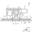
- FIG. 12 is a cross-sectional view of a conventional ultrasonic sensor 502 disclosed in Patent Document 1.
- the ultrasonic sensor 502 is used by being attached to a member to be attached 503 such as an automobile bumper.
- the ultrasonic sensor 502 in FIG. 12 is attached to the attached member 503 by being held by a fixing member 501 that is fixed to the attached member 503.
- the attached member 503 is provided with a through hole 530 that exposes an exposed surface 710 that is a surface on which ultrasonic waves mainly enter and exit in the ultrasonic sensor 502.
- the dimensions and shapes of the ultrasonic sensor 502 and the fixing member 501 are such that the surface opposite to the surface on which the fixing member 501 is fixed in the attached member 503 (for example, the outer surface of the bumper) and the exposed surface 710 are substantially flush. Designed.
- the double-sided tape 610 is referred to in advance as one surface of the fixing member 1 (hereinafter referred to as "adhering surface").
- the pressing is achieved by pressing the double-sided tape 610 against the attached member 503.
- the double-sided tape 610 when used as described above, if the double-sided tape 610 contacts the attached member 503 at a position shifted from the position where the fixing member 501 is to be fixed, the fixing member 501 is at that position. There is a possibility of being fixed.
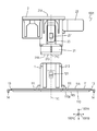
- FIG. 13 is a front view of a conventional fixing member 601 disclosed in Patent Document 2.
- the fixing member 601 is provided with a protrusion 691 that prevents the double-sided tape 610 from contacting the attached member 503 by contacting the attached member 503 before the double-sided tape 610.
- the position of the fixing member 601 can be finely adjusted while avoiding the contact of the double-sided tape 610 with respect to the attached member 503 by bringing the protrusion 691 into contact with the attached member 503. Therefore, workability is improved.
- the fixing member is used for fixing the mounting member to the mounted member.
- the fixing member includes a holding portion that holds the mounting member, a fixing portion that is attached to the attached member, a contact portion that is provided at a position where the fixing portion is sandwiched between the holding portion, and a fixing portion that fixes the contact portion. And a connecting portion for connecting to.
- the contact portion protrudes from the fixed portion toward the attachment member by a protruding dimension.
- the connecting portion connects the contact portion to the fixed portion so that the protruding dimension of the contact portion is variable.
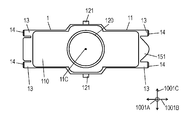
- FIG. 1 is a front view of the ultrasonic sensor device according to the embodiment.
- FIG. 2 is a front view showing the fixing member and the ultrasonic sensor in the ultrasonic sensor device according to the embodiment.
- FIG. 3 is a schematic view of a vehicle to which the ultrasonic sensor device according to the embodiment is attached.
- FIG. 4A is a top view of the fixing member in the ultrasonic sensor device according to the embodiment.
- FIG. 4B is a bottom view of the fixing member according to the embodiment.
- FIG. 5 is a cross-sectional view of the ultrasonic sensor device according to the embodiment.
- FIG. 6 is a cross-sectional view of another ultrasonic sensor device according to the embodiment.
- FIG. 7 is a sectional view of a fixing member of the ultrasonic sensor device shown in FIG.
- FIG. 8 is a cross-sectional view showing the main part in a state where the fixing member in the ultrasonic sensor device shown in FIG. 6 is stuck to the attached member.
- FIG. 9 is a front view of the ultrasonic sensor device according to the embodiment fixed to a curved attached member.
- FIG. 10A is a cross-sectional view of still another fixing member according to the embodiment.
- FIG. 10B is a cross-sectional view of still another fixing member according to the embodiment.
- FIG. 11A is a cross-sectional view of still another fixing member in the embodiment.
- FIG. 11B is a cross-sectional view of still another fixing member in the embodiment.
- FIG. 11C is a cross-sectional view of still another fixing member in the embodiment.
- FIG. 12 is a cross-sectional view of a conventional ultrasonic apparatus.
- FIG. 13 is a front view of another conventional fixing member.
- FIG. 1 is a front view of an ultrasonic sensor device 1001 which is an obstacle detection device according to an embodiment fixed to a member 3 to be attached.
- the ultrasonic sensor device 1001 includes an ultrasonic sensor 2 and a fixing member 1 that fixes the ultrasonic sensor 2 to the attached member 3.
- FIG. 2 is a front view of the ultrasonic sensor device 1001 showing the ultrasonic sensor 2 and the fixing member 1.
- 4A and 4B are a top view and a bottom view of the fixing portion 11, respectively.
- a vertical direction 1001A, a horizontal direction 1001B perpendicular to the vertical direction 1001A, and a longitudinal direction 1001C perpendicular to the vertical direction 1001A and the horizontal direction 1001B are defined.
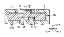
- the fixing member 1 includes a fixing portion 11 having an attaching surface 11B attached to the attached member 3 and holding portions 212 and 312 that hold the ultrasonic sensor 2 that is an attaching member.
- the attached member 3 has an upper surface 3A to which the fixing member 1 is fixed.
- the fixing portion 11 protrudes from the holding portions 212 and 312 in the left-right direction 1001B.
- the sticking surface 11B of the fixing part 11 is the lower surface.
- terms indicating directions such as “vertical direction”, “horizontal direction”, “front / rear direction”, “upper surface”, and “lower surface” are relative only determined by the relative positional relationship of the constituent members of the fixing member 1. It indicates the direction, not the absolute direction such as the vertical direction.
- the ultrasonic sensor 2 has a columnar main body 21 extending along a central axis 21C in the vertical direction 1001A.
- the ultrasonic sensor 2 has an upper surface 21A and a lower surface 21B located on the central axis 21C and opposite to each other.
- the main body 21 houses and holds a piezoelectric element used for transmitting and receiving ultrasonic waves.
- the lower surface 21B of the main body 21 is an exposed surface 210 where ultrasonic waves are input and output.
- a connector portion 22 is connected to the upper surface 21 ⁇ / b> A of the main body portion 21.
- the main body 21 stores and holds a signal processing circuit that performs appropriate signal processing such as amplification of an electric signal input to the piezoelectric element and noise removal and amplification of an electric signal output from the piezoelectric element.
- the connector part 22 protrudes to the right, which is one side of the left-right direction 1001B perpendicular to the central axis 21C of the main body part 21, and an opening is provided at the right end.
- a plurality of contacts made of a conductive material and electrically connected to the signal processing circuit are accommodated in the connector portion 22. That is, when a plug provided at one end of the electric wire is inserted into the connector portion 22, the contact of the plug is brought into contact with the contact of the connector portion 22, thereby electrically connecting the electric wire and the signal processing circuit. Is achieved.
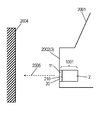
- FIG. 3 is a schematic diagram of a vehicle 2001 to which an ultrasonic sensor device 1001 according to this embodiment is attached.
- the vehicle 2001 has an exterior plate 2002 such as a bumper.
- the exterior plate 2002 such as a bumper is the attached member 3
- the attached member 3 (exterior plate 2002) has a circular through hole 30 that exposes the exposed surface 210 of the ultrasonic sensor 2.
- the ultrasonic sensor 2 is a sensor that detects the obstacle 2004 by the ultrasonic wave 2005 radiated from the exposed surface 210 through the through hole 30.
- the fixing member 1 is composed of one part made of, for example, a synthetic resin.
- the fixing portion 11 is flat in the vertical direction 1001A, that is, is a flat plate that is flat as a whole extending in the left-right direction 1001B and the front-rear direction 1001C. It is attached to the upper surface 3A (for example, the inner surface of a bumper of a vehicle).
- a through hole 120 is provided in the center of the fixed portion 11 so that the main body portion 21 is inserted and penetrates from the upper surface 11A to the lower surface 11B.
- Two holding portions 212 and 312 are provided on both sides of the through-hole 120 in the front-rear direction 1001C.
- Each of the holding portions 212 and 312 has a plate shape that extends substantially perpendicular to the thickness direction facing the front-rear direction 1001 ⁇ / b> C, and protrudes upward from the upper surface 11 ⁇ / b> A of the fixing portion 11.
- the ultrasonic sensor 2 has two sandwiching portions 23 each having a plate shape extending at right angles to the thickness direction facing the front-rear direction 1001C.
- the sandwiching part 23 is connected to the other part of the ultrasonic sensor 2 only at the upper end part.
- the lower end portion of the clip portion 23 can be elastically deformed so as to be displaced in the front-rear direction 1001C.
- the holding portions 212 and 312 of the fixing member 1 are sandwiched between one sandwiching portion 23 and the main body portion 21 in the front-rear direction 1001C.
- the holding part 212 has surfaces 212A and 212B opposite to each other.
- the holding portion 312 has opposite surfaces 312A and 312B.
- the surfaces 212B and 312B of the holding portions 212 and 312 face each other in the front-rear direction 1001C.
- the surfaces 212A and 312A of the holding portions 212 and 312 face outward in the direction away from each other in the front-rear direction 1001C.
- Engaging convex portions 121 are provided on the surfaces 212A and 312A of the holding portions 212 and 312.
- Each pinching portion 23 is provided with an engagement hole 231.
- the ultrasonic sensor 2 is coupled to the fixing member 1 by the engagement protrusions 121 engaging with the engagement holes 231.
- the engagement convex portion 121 can be engaged / disengaged with respect to the engagement hole 231, whereby the ultrasonic sensor 2 is detachable from the fixing member 1.
- the engagement hole 231 may be a through-hole, or may be a recess opened only on a surface directed to the holding portions 212 and 312.
- linear grooves 111 that extend in the front-rear direction 1001C and are opened are provided.
- the fixing portion 11 is locally thin at the bottom of the groove 111, so that both ends of the fixing portion 11 in the left-right direction 1001 ⁇ / b> B are upward with respect to the central portion (that is, with respect to the holding portions 212 and 312). It can be deformed to be displaced up to the upper limit.
- a V-shaped groove 112 is provided on the upper surface 11A of the fixed portion 11 from the center portion at both ends in the left-right direction 1001B to both ends in the front-rear direction 1001C of the groove 111. Since the fixing portion 11 is locally thin at the bottom of the groove 112, the fixing portion 11 can be deformed so that the vicinity of the four corners of the fixing portion 11 is displaced in the vertical direction 1001A with respect to the central portion.
- the fixing member 1 has a shape that does not have two or more rotational symmetry with respect to the axis 11C orthogonal to the attaching surface 11B, that is, an asymmetric shape with respect to the axis 11C.
- a mounting direction display portion 151 that is a triangular convex portion is provided at the right end of the fixed portion 11, and a rectangular convex portion at the left end of the fixed portion 11.
- a mounting direction display portion 152 is provided. The fact that the tip of the connector part 22 should be attached toward the attachment direction display part 151 on the right side is displayed in the fixing member 1 itself or a manual attached to the fixing member 1. That is, the attachment direction display portions 151 and 152 indicate the direction of the ultrasonic sensor 2 as the attachment member with respect to the fixed member 1.
- slide grooves 153 extending in the vertical direction 1001A opened upward are provided on the inwardly facing surfaces 212B and 312B in the front-rear direction 1001C of the holding portions 212 and 312 respectively. Yes.
- one slide groove 153 is provided on the surface 312B of the front holding portion 312, and two slide grooves 153 are provided side by side in the left-right direction 1001B on the rear holding portion 212.
- FIGS. 5 and 6 are cross-sectional views of the ultrasonic sensor device 1001, and show the peripheral portions of the holding unit 212 and the holding unit 312 respectively.
- the ultrasonic sensor 2 is provided with three slide convex portions 24 corresponding to the slide groove 153 on a one-to-one basis. If each slide convex portion 24 is not in the correct orientation to be introduced into the corresponding slide groove 153, the slide convex portion 24 and the holding portions 212 and 312 interfere with each other, so the ultrasonic sensor 2 is attached to the fixing member 1. I can't. That is, the slide groove 153 is a restricting portion for restricting the direction of the ultrasonic sensor 2 that is an attachment member with respect to the fixing member 1.
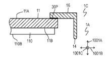
- the fixing member 1 protrudes downward from the side surfaces of the fixing portion 11 in the left-right direction 1001B and outwardly projecting away from each other (four in this embodiment) and from the tip of the connecting portion 13. And a plurality of (four in this embodiment) contact portions 14.
- Four connecting portions 13, that is, contact portions 14 are provided at the four corners of the fixing portion 11, respectively.
- the connecting portion 13 has a thickness dimension (dimension in the vertical direction 1001A) smaller than that of the fixed portion 11 where the grooves 111 and 112 are not provided, and the contact portion 14 is positioned in the vertical direction with respect to the fixed portion 11.
- transformation which is displaced to 1001A is possible.
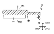
- FIG. 7 is a cross-sectional view of the fixing member 1 and shows an end portion of the fixing portion 11 in the left-right direction 1001B.
- the contact part 14 protrudes from the lower surface 11B by the protrusion dimension H1 to the lower side of the fixed part 11 in a state where the connecting part 13 is not deformed.
- the contact portion 14 protrudes downward from the lower surface 110B of the double-sided tape 110 attached to the lower surface 11B of the fixed portion 11 by a protrusion dimension H2.
- the protruding dimension H1 is larger than the protruding dimension H2.
- the lower end of the contact portion 14 protrudes below the lower surface 110 ⁇ / b> B of the double-sided tape 110. That is, the lower end of the contact portion 14 is one side in the thickness direction of the fixed portion 11 and protrudes in the direction opposite to the direction in which the holding portions 212 and 312 protrude with respect to the fixed portion 11. Moreover, the deformation
- FIG. 8 is a cross-sectional view of the fixing member 1 and shows an end portion of the fixing portion 11 in the left-right direction 1001B.
- the contact portion 14 comes into contact with the attached member 3 before the double-sided tape 110, thereby preventing the double-sided tape 110 from contacting the attached member 3.
- a downward force is applied to the holding portions 212 and 312 to deform the fixing portion 11 and the connecting portion 13 as shown in FIG.
- the tape 110 is pressed against the attached member 3 and attached.
- the fixing member 1 can be easily aligned while maintaining the state where the fixing portion 11 and the double-sided tape 110 do not contact the attached member 3. Thereby, workability
- operativity is improved compared with the fixing member in which the contact part 14 is not provided.
- a fixing portion 511 that is a portion that is attached to the attached member 503 and a holding portion 512 that is a portion that holds the ultrasonic sensor 502 are interposed via a plate-shaped bracket 519.
- the connecting portion between the fixing portion 511 and the holding portion 512 and the bracket 519 is made thinner than the other portions, and this causes deformation that displaces the fixing portion 511 and the bracket 519 with respect to the holding portion 512. It is possible.
- the operator holds the holding portion 512.
- the protrusion 691 is provided on the bracket 519. That is, the protrusion 691 is located between the fixing portion 511 and the holding portion 512.
- the protrusion 691 comes into contact with the attached member 503 before the double-sided tape 610.
- the protrusion 691 is located between the fixing part 511 and the holding part 512. Therefore, in the conventional fixing member 601 shown in FIG. 13, when the fixing portion 511 is attached to the attached member 503, the holding portion 512 is held rather than the protrusion 691 in a state where the holding portion 512 is held for alignment. Therefore, it is necessary to apply a pressing force to the fixing portion 511 away from the head, and workability is relatively lowered.
- the contact portion 14 which is a portion that comes into contact with the attached member 3 before the double-sided tape 110, has the fixing portion 11 between the holding portions 212 and 312. It is provided in the position to pinch. That is, the contact portion 14 is provided on the opposite side of the holding portions 212 and 312 with respect to the fixed portion 11. Therefore, at the time of attaching the fixing portion 11 to the attached member 3, the operator attaches the fixing portion 11 only by applying force to the holding portions 212 and 312 which are portions to be held for alignment. It can be pressed against the member 3.
- the fixing portion 11 can be pressed against the attached member 3 while holding the holding portions 212 and 312 when the fixing portion 11 is attached to the attached member 3. It becomes relatively easy and workability is improved.
- the part of the double-sided tape 110 that is away from the holding parts 212 and 312 is ahead of the part that is close to the holding parts 212 and 312.
- the positioning of the holding portions 212 and 312 with respect to the through hole 30 of the attached member 3 becomes relatively difficult.
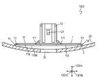
- FIG. 9 is a front view of the ultrasonic sensor device 1001 fixed to the curved attached member 3.
- the contact portion 14 is located farther from the holding portions 212 and 312 than the fixing portion 11, so that the holding portion 212 of the fixing portion 11 (double-sided tape 110), Compared to the part further away from 312, the part closer to the holding parts 212, 312 tends to contact the attached member 3 first. Therefore, in the fixing member 1 according to the present embodiment, the positioning of the holding portions 212 and 312 with respect to the through hole 30 of the attached member 3 is relatively easy.
- an adhesive may be used in place of the double-sided tape 110 as an attaching means for attaching the fixing portion 11 to the attached member 3.
- the number of the plurality of contact portions 14 is not necessarily four. However, in order to stabilize the posture of the fixing member 1 in a state in which each contact portion 14 is in contact with the attached member 3, three or more contact portions 14 are viewed from above (that is, on the attached member 3). It is desirable to be provided in an arrangement surrounding the holding parts 212, 312 (in the projection to the
- the fixing member 1 is used for fixing the mounting member 2 (ultrasonic sensor) to the mounted member 3.
- the fixing member 1 is located at a position where the fixing portion 11 is sandwiched between the holding portion 212 (312) that holds the attachment member 2, the fixing portion 11 that is attached to the attached member 3, and the holding portion 212 (312).
- the provided contact part 14 and the connection part 13 which connects the contact part 14 with respect to the fixing
- the contact portion 14 protrudes from the fixed portion 11 toward the mounted member 3 by a protruding dimension, and contacts the mounted member 3 before the fixed portion 11 when being fixed to the mounted member 3.
- the connecting part 13 connects the contact part 14 to the fixed part 11 so that the protruding dimension of the contact part 14 can be changed.
- the fixing part 11 may be a plate shape in which the attaching surface 11B in the thickness direction is attached to the member 3 to be attached.
- the holding part 212 (312) protrudes from the fixing part 11 in one direction in the thickness direction (vertical direction 1001A) of the fixing part 11.
- the contact portion 14 protrudes to the other side in the thickness direction of the fixed portion rather than the fixed portion 11.
- the fixing portion 11 may have a plate shape having an attachment surface 11B attached to the attached member 3 and a certain surface (upper surface 11A) opposite to the attachment surface 11B.
- the holding portions 212 and 312 protrude from a certain surface (upper surface 11A) of the fixing portion 11, and the contact portion 14 protrudes from the sticking surface 11B of the fixing portion 11.
- the connecting portion 13 may be connected to a surface of the fixed portion 11 that faces the attached member 3. That is, the connecting part 13 may be connected to the sticking surface 11B of the fixing part 11.
- the fixing part 11, the connecting part 13, and the contact part 14 may be integrally molded.
- the connecting portion 13 is formed thinner than both the fixed portion 11 and the contact portion 14.
- the three or more contact portions 14 may be arranged so as to surround the holding portion 212 (312) in the projection onto the attached member 3.
- FIG. 10A is a cross-sectional view of another fixing member 1A according to the present embodiment. 10A, the same reference numerals are given to the same portions as those of the fixing member 1 shown in FIG.
- the thickness direction of the connecting portion 13 intersects the sticking surface 11B.
- the thickness direction of the connection part 13 is the direction along the sticking surface 11B (FIG. 10A left-right direction 1001B).
- the contact portion 14 is connected to the lower surface, which is the attaching surface 11 ⁇ / b> B directed to the attached member 3, via the connecting portion 13.
- FIG. 10B is a cross-sectional view of another fixing member 1B according to the present embodiment. 10B, the same reference numerals are assigned to the same portions as those of the fixing member 1A shown in FIG. 10A.
- the contact portion 14 is connected to the lower surface, which is the sticking surface 11B directed to the attached member 3, via the connecting portion 13. Accordingly, the dimension and shape of the fixing member 1B viewed from the direction perpendicular to the vertical direction 1001A, that is, the attaching surface 11B, as compared with the fixing member 1 in which the contact portion 14 shown in FIGS. 1 to 8 is coupled to the side surface of the fixing portion 11. That is, the occupation area of the fixing member 1 on the attached member 3 can be reduced.
- FIG. 11A is a cross-sectional view of still another fixing member 1C according to the present embodiment.
- the contact portion 14 is composed of a component separate from the fixing portion 11.
- the contact part 14 has the sticking part 16 stuck on the upper surface 11A of the fixing
- the contact member 14 P is peeled off by the reaction force that the contact portion 14 receives from the attached member 3, and the sticking portion 16 is peeled off from the fixing portion 11.
- the part 14 is displaced. That is, the adhesive member 30P constitutes a connecting portion.
- FIG. 11B is a cross-sectional view of still another fixing member 1D according to the present embodiment. 11B, the same reference numerals are assigned to the same portions as those of the fixing member 1 shown in FIG.
- a part of the contact portion 14 is accommodated in the recess 113 provided on the lower surface 11 ⁇ / b> B of the fixing portion 11.
- a ball joint 113 ⁇ / b> A that variably supports the protruding dimension that the contact portion 14 protrudes from the lower surface 11 ⁇ / b> B of the fixing portion 11 is provided in the recess 113.
- the ball joint 113A functions as a coupling portion that makes the protruding dimension of the contact portion 14 variable.
- FIG. 11C is a cross-sectional view of still another fixing member 1E according to the present embodiment.
- the same reference numerals are given to the same portions as those of the fixing member 1D shown in FIG. 11B.
- the fixing portion 11 has a support shaft 113B that makes the angle A14 of the contact portion 14 inclined with respect to the lower surface 11B variable.
- the support shaft 113 ⁇ / b> B functions as a coupling portion that makes the projecting dimension that the contact portion 14 projects from the sticking surface 11 ⁇ / b> B of the fixed portion 11 variable.
- the fixing member according to the present invention can improve the fixing workability of the mounting member, and is useful for an apparatus including the mounting member.
Abstract
This fastening member is employed for fastening a member for attachment to a member for receiving attachment. The fastening member is provided with: a retaining portion for retaining a member for attachment; a fastening portion adhered to a member for receiving attachment; a contact portion provided at a location sandwiching the fastening portion between itself and the retaining portion; and a linking portion for linking the contact portion to the fastening portion. The contact portion protrudes out by a given protruding dimension beyond the fastening portion, towards the member for receiving attachment. The linking portion links the contact portion to the fastening portion in such a way that the protruding dimension of the contact portion is variable. With this fastening member, ease of operation can be improved.
Description
本発明は、取付部材の固定に用いられる固定部材及び該固定部材を用いた障害物検知装置に関する。
The present invention relates to a fixing member used for fixing an attachment member and an obstacle detection device using the fixing member.
超音波を送信するとともに障害物で反射された超音波を受信する超音波センサは、例えば、送信した超音波が障害物において反射された反射波の受信の有無に基いて障害物の有無を検出するとともに、超音波を送信してから反射波が受信されるまでの時間に基いて障害物までの距離を検出する。
An ultrasonic sensor that transmits ultrasonic waves and receives ultrasonic waves reflected by obstacles, for example, detects the presence or absence of obstacles based on whether or not the transmitted ultrasonic waves are reflected by the obstacles. In addition, the distance to the obstacle is detected based on the time from when the ultrasonic wave is transmitted until the reflected wave is received.
図12は特許文献1に開示されている従来の超音波センサ502の断面図である。超音波センサ502は、自動車のバンパーのような被取付部材503に取り付けて用いられる。
FIG. 12 is a cross-sectional view of a conventional ultrasonic sensor 502 disclosed in Patent Document 1. The ultrasonic sensor 502 is used by being attached to a member to be attached 503 such as an automobile bumper.
図12の超音波センサ502は、被取付部材503に対して固定される固定部材501に保持されることで、被取付部材503に取り付けられる。被取付部材503には超音波センサ502において超音波が主に入射および出射する面である露出面710を露出させる貫通孔530が設けられている。超音波センサ502及び固定部材501の寸法と形状は、被取付部材503において固定部材501が固定される面の反対の面(例えばバンパーの外面)と露出面710とが略面一となるように設計されている。
The ultrasonic sensor 502 in FIG. 12 is attached to the attached member 503 by being held by a fixing member 501 that is fixed to the attached member 503. The attached member 503 is provided with a through hole 530 that exposes an exposed surface 710 that is a surface on which ultrasonic waves mainly enter and exit in the ultrasonic sensor 502. The dimensions and shapes of the ultrasonic sensor 502 and the fixing member 501 are such that the surface opposite to the surface on which the fixing member 501 is fixed in the attached member 503 (for example, the outer surface of the bumper) and the exposed surface 710 are substantially flush. Designed.
上記のような固定部材501において、被取付部材503に対する固定が両面テープ610を用いた貼着により行われる場合、両面テープ610は予め固定部材1の一面(以下、「貼着面」と呼ぶ。)に貼着され、この両面テープ610を被取付部材503に押し付けることで貼着が達成される。
In the fixing member 501 as described above, when the fixing to the attached member 503 is performed by adhering using the double-sided tape 610, the double-sided tape 610 is referred to in advance as one surface of the fixing member 1 (hereinafter referred to as "adhering surface"). ) And the pressing is achieved by pressing the double-sided tape 610 against the attached member 503.
しかしながら、上記のように両面テープ610が用いられる場合、固定部材501が固定されるべき位置からずれた位置で両面テープ610が被取付部材503に接触してしまうと、固定部材501がその位置で固定されてしまう可能性がある。
However, when the double-sided tape 610 is used as described above, if the double-sided tape 610 contacts the attached member 503 at a position shifted from the position where the fixing member 501 is to be fixed, the fixing member 501 is at that position. There is a possibility of being fixed.
図13は特許文献2に開示されている従来の固定部材601の正面図である。図13に示すように、両面テープ610よりも先に被取付部材503に接触することで被取付部材503に対する両面テープ610の接触を阻止する突起691が固定部材601に設けられている。
FIG. 13 is a front view of a conventional fixing member 601 disclosed in Patent Document 2. FIG. As shown in FIG. 13, the fixing member 601 is provided with a protrusion 691 that prevents the double-sided tape 610 from contacting the attached member 503 by contacting the attached member 503 before the double-sided tape 610.
上記構成によれば、突起691を被取付部材503に接触させることで被取付部材503に対する両面テープ610の接触を避けつつ固定部材601の位置を微調整することができるから、作業性が改善される。
According to the above configuration, the position of the fixing member 601 can be finely adjusted while avoiding the contact of the double-sided tape 610 with respect to the attached member 503 by bringing the protrusion 691 into contact with the attached member 503. Therefore, workability is improved. The
固定部材は被取付部材に対する取付部材の固定に用いられる。その固定部材は、取付部材を保持する保持部と、被取付部材に貼着される固定部と、保持部との間に固定部を挟む位置に設けられた接触部と、接触部を固定部に対して連結する連結部とを備える。接触部は、固定部よりも被取付部材へ向かって突出寸法だけ突出する。連結部は、接触部の突出寸法を可変とするように接触部を固定部に対して連結する。
The fixing member is used for fixing the mounting member to the mounted member. The fixing member includes a holding portion that holds the mounting member, a fixing portion that is attached to the attached member, a contact portion that is provided at a position where the fixing portion is sandwiched between the holding portion, and a fixing portion that fixes the contact portion. And a connecting portion for connecting to. The contact portion protrudes from the fixed portion toward the attachment member by a protruding dimension. The connecting portion connects the contact portion to the fixed portion so that the protruding dimension of the contact portion is variable.
この固定部材は作業性を改善することができる。
¡This fixing member can improve workability.
図1は被取付部材3に固定された実施形態に係る障害物検知装置である超音波センサ装置1001の正面図である。超音波センサ装置1001は、超音波センサ2と、超音波センサ2を被取付部材3に固定する固定部材1とを備える。
FIG. 1 is a front view of an ultrasonic sensor device 1001 which is an obstacle detection device according to an embodiment fixed to a member 3 to be attached. The ultrasonic sensor device 1001 includes an ultrasonic sensor 2 and a fixing member 1 that fixes the ultrasonic sensor 2 to the attached member 3.
図2は超音波センサ2と固定部材1とを示す超音波センサ装置1001の正面図である。図4Aと図4Bはそれぞれ固定部11の上面図と下面図である。図1と図2に示すように、上下方向1001Aと、上下方向1001Aに直角の左右方向1001Bと、上下方向1001Aと左右方向1001Bとに直角の前後方向1001Cとを定義する。固定部材1は、被取付部材3に貼着される貼着面11Bを有する固定部11と、取付部材である超音波センサ2を保持する保持部212、312とを有する。被取付部材3は固定部材1が固定される上面3Aを有する。保持部212、312から固定部11が左右方向1001Bに突出する。固定部11の貼着面11Bは下面である。なお、実施形態において、「上下方向」「左右方向」「前後方向」「上面」「下面」等の方向を示す用語は、固定部材1の構成部材の相対的な位置関係でのみ決まる相対的な方向を示し、鉛直方向等の絶対的な方向を示すものではない。
FIG. 2 is a front view of the ultrasonic sensor device 1001 showing the ultrasonic sensor 2 and the fixing member 1. 4A and 4B are a top view and a bottom view of the fixing portion 11, respectively. As shown in FIGS. 1 and 2, a vertical direction 1001A, a horizontal direction 1001B perpendicular to the vertical direction 1001A, and a longitudinal direction 1001C perpendicular to the vertical direction 1001A and the horizontal direction 1001B are defined. The fixing member 1 includes a fixing portion 11 having an attaching surface 11B attached to the attached member 3 and holding portions 212 and 312 that hold the ultrasonic sensor 2 that is an attaching member. The attached member 3 has an upper surface 3A to which the fixing member 1 is fixed. The fixing portion 11 protrudes from the holding portions 212 and 312 in the left-right direction 1001B. The sticking surface 11B of the fixing part 11 is the lower surface. In the embodiment, terms indicating directions such as “vertical direction”, “horizontal direction”, “front / rear direction”, “upper surface”, and “lower surface” are relative only determined by the relative positional relationship of the constituent members of the fixing member 1. It indicates the direction, not the absolute direction such as the vertical direction.
超音波センサ2は、上下方向1001Aの中心軸21Cに沿って延びる円柱形状の本体部21を有する。超音波センサ2は、中心軸21C上に位置して互いに反対側の上面21Aと下面21Bとを有する。本体部21には超音波の送受信に用いられる圧電素子が収納及び保持されている。本体部21の下面21Bは超音波が入出力される露出面210である。また、本体部21の上面21Aには、コネクタ部22が連結されている。本体部21には、上記の圧電素子に入力される電気信号に対する増幅や、上記の圧電素子が出力する電気信号に対するノイズ除去や増幅といった、適宜の信号処理を行う信号処理回路が収納及び保持されている。コネクタ部22は本体部21の中心軸21Cに直角の左右方向1001Bの一方側である右側へ突出しており、右側の先端には開口が設けられている。コネクタ部22内には、導電材料からなり上記の信号処理回路に電気的に接続された複数個のコンタクトが収納されている。すなわち、電線の一端に設けられたプラグがコネクタ部22に挿入されると、プラグが有するコンタクトがコネクタ部22のコンタクトに接触導通することで、上記の電線と信号処理回路との電気的な接続が達成される。
The ultrasonic sensor 2 has a columnar main body 21 extending along a central axis 21C in the vertical direction 1001A. The ultrasonic sensor 2 has an upper surface 21A and a lower surface 21B located on the central axis 21C and opposite to each other. The main body 21 houses and holds a piezoelectric element used for transmitting and receiving ultrasonic waves. The lower surface 21B of the main body 21 is an exposed surface 210 where ultrasonic waves are input and output. A connector portion 22 is connected to the upper surface 21 </ b> A of the main body portion 21. The main body 21 stores and holds a signal processing circuit that performs appropriate signal processing such as amplification of an electric signal input to the piezoelectric element and noise removal and amplification of an electric signal output from the piezoelectric element. ing. The connector part 22 protrudes to the right, which is one side of the left-right direction 1001B perpendicular to the central axis 21C of the main body part 21, and an opening is provided at the right end. A plurality of contacts made of a conductive material and electrically connected to the signal processing circuit are accommodated in the connector portion 22. That is, when a plug provided at one end of the electric wire is inserted into the connector portion 22, the contact of the plug is brought into contact with the contact of the connector portion 22, thereby electrically connecting the electric wire and the signal processing circuit. Is achieved.
図3は本実施形態に係る超音波センサ装置1001が取り付けられた車両2001の模式図である。車両2001はバンパー等の外装板2002を有する。本実施の形態では、バンパー等の外装板2002は被取付部材3であり、被取付部材3(外装板2002)には、超音波センサ2の露出面210を露出させる円形状の貫通孔30が設けられている。本実施の形態に係る障害物検知装置である超音波センサ装置1001では、超音波センサ2は、露出面210から貫通孔30を通して放射する超音波2005により障害物2004を検知するセンサである。
FIG. 3 is a schematic diagram of a vehicle 2001 to which an ultrasonic sensor device 1001 according to this embodiment is attached. The vehicle 2001 has an exterior plate 2002 such as a bumper. In the present embodiment, the exterior plate 2002 such as a bumper is the attached member 3, and the attached member 3 (exterior plate 2002) has a circular through hole 30 that exposes the exposed surface 210 of the ultrasonic sensor 2. Is provided. In the ultrasonic sensor device 1001 that is the obstacle detection device according to the present embodiment, the ultrasonic sensor 2 is a sensor that detects the obstacle 2004 by the ultrasonic wave 2005 radiated from the exposed surface 210 through the through hole 30.
固定部材1は、例えば合成樹脂からなる1個の部品で構成されている。固定部11は上下方向1001Aに扁平な、すなわち左右方向1001Bと前後方向1001Cとに広がる扁平な全体として長方形の板状であって、下面11Bに貼着された両面テープ110により被取付部材3の上面3A(例えば車両のバンパーの内面)に貼着される。また、固定部11の中央部には本体部21が挿入されて上面11Aから下面11Bを貫通する貫通孔120が設けられている。貫通孔120の前後方向1001Cの両側には2つの保持部212、312がそれぞれ設けられている。保持部212、312はそれぞれ前後方向1001Cに向く厚さ方向に直角に広がる板形状を実質的に有し、固定部11の上面11Aから上方に突出している。超音波センサ2は、前後方向1001Cに向く厚さ方向に直角に広がる板形状を有する2つの挟み部23を有する。挟み部23は、その上端部のみで超音波センサ2の他の部位に連結されている。挟み部23の下端部は前後方向1001Cに変位させるように弾性変形可能となっている。固定部材1の各保持部212、312は、前後方向1001Cにおいてそれぞれ1つの挟み部23と本体部21との間に挟まれる。保持部212は互いに反対側の面212A、212Bを有する。保持部312は互いに反対側の面312A、312Bを有する。保持部212、312の面212B、312Bは前後方向1001Cにおいて互いに対向する。保持部212、312の面212A、312Aは前後方向1001Cにおいて互いに離れる方向の外側に向いている。各保持部212、312の面212A、312Aには係合凸部121が設けられている。各挟み部23にはそれぞれ係合穴231が設けられている。各係合凸部121が係合穴231に係入することで、超音波センサ2は固定部材1に結合する。挟み部23を一時的に弾性変形させることで係合穴231に対して係合凸部121を係脱することができ、これによって超音波センサ2は固定部材1に対して着脱自在となっている。上記の係合穴231は貫通孔であってもよいし、保持部212、312に向けられる面のみに開口した凹部であってもよい。
The fixing member 1 is composed of one part made of, for example, a synthetic resin. The fixing portion 11 is flat in the vertical direction 1001A, that is, is a flat plate that is flat as a whole extending in the left-right direction 1001B and the front-rear direction 1001C. It is attached to the upper surface 3A (for example, the inner surface of a bumper of a vehicle). In addition, a through hole 120 is provided in the center of the fixed portion 11 so that the main body portion 21 is inserted and penetrates from the upper surface 11A to the lower surface 11B. Two holding portions 212 and 312 are provided on both sides of the through-hole 120 in the front-rear direction 1001C. Each of the holding portions 212 and 312 has a plate shape that extends substantially perpendicular to the thickness direction facing the front-rear direction 1001 </ b> C, and protrudes upward from the upper surface 11 </ b> A of the fixing portion 11. The ultrasonic sensor 2 has two sandwiching portions 23 each having a plate shape extending at right angles to the thickness direction facing the front-rear direction 1001C. The sandwiching part 23 is connected to the other part of the ultrasonic sensor 2 only at the upper end part. The lower end portion of the clip portion 23 can be elastically deformed so as to be displaced in the front-rear direction 1001C. The holding portions 212 and 312 of the fixing member 1 are sandwiched between one sandwiching portion 23 and the main body portion 21 in the front-rear direction 1001C. The holding part 212 has surfaces 212A and 212B opposite to each other. The holding portion 312 has opposite surfaces 312A and 312B. The surfaces 212B and 312B of the holding portions 212 and 312 face each other in the front-rear direction 1001C. The surfaces 212A and 312A of the holding portions 212 and 312 face outward in the direction away from each other in the front-rear direction 1001C. Engaging convex portions 121 are provided on the surfaces 212A and 312A of the holding portions 212 and 312. Each pinching portion 23 is provided with an engagement hole 231. The ultrasonic sensor 2 is coupled to the fixing member 1 by the engagement protrusions 121 engaging with the engagement holes 231. By temporarily elastically deforming the pinching portion 23, the engagement convex portion 121 can be engaged / disengaged with respect to the engagement hole 231, whereby the ultrasonic sensor 2 is detachable from the fixing member 1. Yes. The engagement hole 231 may be a through-hole, or may be a recess opened only on a surface directed to the holding portions 212 and 312.
また、固定部11の上面11Aにおいて、保持部212、312の左右方向1001Bにおける両側には、それぞれ、前後方向1001Cに延びて開放された直線状の溝111が設けられている。固定部11は、溝111の底部において局部的に薄肉となっていることで、固定部11の左右方向1001Bの両端部を中央部に対して(つまり保持部212、312に対して)上方に上限まで変位させるように変形可能となっている。また、固定部11の上面11Aには、左右方向1001Bの両端の中央部から溝111の前後方向1001Cの両端部にかけて、V字形状の溝112が設けられている。固定部11は、溝112の底部において局部的に薄肉となっていることで、固定部11の4隅付近を中央部に対して上下方向1001Aに変位させるように変形可能となっている。
Further, on the upper surface 11A of the fixing portion 11, on both sides of the holding portions 212 and 312 in the left-right direction 1001B, linear grooves 111 that extend in the front-rear direction 1001C and are opened are provided. The fixing portion 11 is locally thin at the bottom of the groove 111, so that both ends of the fixing portion 11 in the left-right direction 1001 </ b> B are upward with respect to the central portion (that is, with respect to the holding portions 212 and 312). It can be deformed to be displaced up to the upper limit. Further, a V-shaped groove 112 is provided on the upper surface 11A of the fixed portion 11 from the center portion at both ends in the left-right direction 1001B to both ends in the front-rear direction 1001C of the groove 111. Since the fixing portion 11 is locally thin at the bottom of the groove 112, the fixing portion 11 can be deformed so that the vicinity of the four corners of the fixing portion 11 is displaced in the vertical direction 1001A with respect to the central portion.
また、固定部材1は、貼着面11Bに直交する軸11Cに関して2回以上の回転対称性を有さない形状、すなわち軸11Cについて非対称の形状を有する。
Further, the fixing member 1 has a shape that does not have two or more rotational symmetry with respect to the axis 11C orthogonal to the attaching surface 11B, that is, an asymmetric shape with respect to the axis 11C.
具体的には、図4Aと図4Bに示すように、固定部11の右端には三角形状の凸部である取付向き表示部151が設けられ、固定部11の左端には長方形状の凸部である取付向き表示部152が設けられている。コネクタ部22の先端を右側の取付向き表示部151へ向けて取り付けるべきことが、固定部材1自体や固定部材1に添付される説明書において表示される。すなわち、取付向き表示部151、152は固定部材1に対する取付部材としての超音波センサ2の向きを示す。
Specifically, as shown in FIGS. 4A and 4B, a mounting direction display portion 151 that is a triangular convex portion is provided at the right end of the fixed portion 11, and a rectangular convex portion at the left end of the fixed portion 11. A mounting direction display portion 152 is provided. The fact that the tip of the connector part 22 should be attached toward the attachment direction display part 151 on the right side is displayed in the fixing member 1 itself or a manual attached to the fixing member 1. That is, the attachment direction display portions 151 and 152 indicate the direction of the ultrasonic sensor 2 as the attachment member with respect to the fixed member 1.
また、図4Aに示すように、保持部212、312において前後方向1001Cの内向きの互いに対向する面212B、312Bには、それぞれ上方に開放された上下方向1001Aに延びるスライド溝153が設けられている。スライド溝153は、前側の保持部312の面312Bに1つのスライド溝153が設けられ、後側の保持部212には2つのスライド溝153が左右方向1001Bに並べて設けられている。
As shown in FIG. 4A, slide grooves 153 extending in the vertical direction 1001A opened upward are provided on the inwardly facing surfaces 212B and 312B in the front-rear direction 1001C of the holding portions 212 and 312 respectively. Yes. In the slide groove 153, one slide groove 153 is provided on the surface 312B of the front holding portion 312, and two slide grooves 153 are provided side by side in the left-right direction 1001B on the rear holding portion 212.
図5と図6は超音波センサ装置1001の断面図であり、それぞれ保持部212と保持部312の周辺の部分を示す。図5及び図6に示すように、超音波センサ2には、スライド溝153に一対一に対応する3個のスライド凸部24が設けられている。各スライド凸部24がそれぞれ対応するスライド溝153に導入されるような正しい向きでなければ、スライド凸部24と保持部212、312とが互いに干渉するから超音波センサ2を固定部材1に取り付けることができない。すなわち、スライド溝153は、取付部材である超音波センサ2の固定部材1に対する方向を規制するための規制部である。
5 and 6 are cross-sectional views of the ultrasonic sensor device 1001, and show the peripheral portions of the holding unit 212 and the holding unit 312 respectively. As shown in FIGS. 5 and 6, the ultrasonic sensor 2 is provided with three slide convex portions 24 corresponding to the slide groove 153 on a one-to-one basis. If each slide convex portion 24 is not in the correct orientation to be introduced into the corresponding slide groove 153, the slide convex portion 24 and the holding portions 212 and 312 interfere with each other, so the ultrasonic sensor 2 is attached to the fixing member 1. I can't. That is, the slide groove 153 is a restricting portion for restricting the direction of the ultrasonic sensor 2 that is an attachment member with respect to the fixing member 1.
さらに、固定部材1は、固定部11の側面から左右方向1001Bの互いに離れる外向きに突出する複数(本実施形態では4つ)の連結部13と、連結部13の先端から下方にそれぞれ突出する複数(本実施形態では4つ)の接触部14とをさらに有する。4つの連結部13すなわち接触部14は固定部11の4隅にそれぞれ設けられている。連結部13は、固定部11における溝111、112が設けられていない部位よりも厚さ寸法(上下方向1001Aでの寸法)を小さくされており、固定部11に対して接触部14を上下方向1001Aに変位させるような変形が可能となっている。
Furthermore, the fixing member 1 protrudes downward from the side surfaces of the fixing portion 11 in the left-right direction 1001B and outwardly projecting away from each other (four in this embodiment) and from the tip of the connecting portion 13. And a plurality of (four in this embodiment) contact portions 14. Four connecting portions 13, that is, contact portions 14 are provided at the four corners of the fixing portion 11, respectively. The connecting portion 13 has a thickness dimension (dimension in the vertical direction 1001A) smaller than that of the fixed portion 11 where the grooves 111 and 112 are not provided, and the contact portion 14 is positioned in the vertical direction with respect to the fixed portion 11. The deformation | transformation which is displaced to 1001A is possible.
図7は固定部材1の断面図であり、固定部11の左右方向1001Bの端部を示す。図7に示すように、連結部13が変形していない状態で固定部11の下方へ接触部14は突出寸法H1だけ下面11Bから突出している。接触部14は、固定部11の下面11Bに貼り付けられた両面テープ110の下面110Bから下方に突出寸法H2だけ突出している。突出寸法H1は突出寸法H2よりも大きくされている。すなわち、連結部13が変形していない状態では、接触部14の下端は両面テープ110の下面110Bよりも下方に突出する。つまり、接触部14の下端は固定部11の厚さ方向の一方であって、固定部11に対する保持部212、312の突出する方向とは逆方向に突出する。また、連結部13が変形することで、固定部11よりも下側、つまり被取付部材3に向かって接触部14の突出する突出寸法H1が小さくなる。すなわち、接触部14は、固定部11よりも被取付部材3側への突出寸法H1を可変とされている。
7 is a cross-sectional view of the fixing member 1 and shows an end portion of the fixing portion 11 in the left-right direction 1001B. As shown in FIG. 7, the contact part 14 protrudes from the lower surface 11B by the protrusion dimension H1 to the lower side of the fixed part 11 in a state where the connecting part 13 is not deformed. The contact portion 14 protrudes downward from the lower surface 110B of the double-sided tape 110 attached to the lower surface 11B of the fixed portion 11 by a protrusion dimension H2. The protruding dimension H1 is larger than the protruding dimension H2. That is, in a state where the connecting portion 13 is not deformed, the lower end of the contact portion 14 protrudes below the lower surface 110 </ b> B of the double-sided tape 110. That is, the lower end of the contact portion 14 is one side in the thickness direction of the fixed portion 11 and protrudes in the direction opposite to the direction in which the holding portions 212 and 312 protrude with respect to the fixed portion 11. Moreover, the deformation | transformation dimension H1 which the contact part 14 protrudes below the fixing | fixed part 11, ie, toward the to-be-attached member 3, becomes small because the connection part 13 deform | transforms. That is, the projecting dimension H <b> 1 of the contact portion 14 toward the attached member 3 side is variable from the fixed portion 11.
図8は固定部材1の断面図であり、固定部11の左右方向1001Bの端部を示す。固定部材1を被取付部材3に固定する過程では、両面テープ110よりも先に接触部14が被取付部材3に接触することで、被取付部材3に対する両面テープ110の接触が阻止される。この状態で、固定部材1の位置を微調整した後、保持部212、312に対して下向きの力を加えることで図8に示すように固定部11と連結部13とをそれぞれ変形させて両面テープ110を被取付部材3に押し付け、貼着する。
FIG. 8 is a cross-sectional view of the fixing member 1 and shows an end portion of the fixing portion 11 in the left-right direction 1001B. In the process of fixing the fixing member 1 to the attached member 3, the contact portion 14 comes into contact with the attached member 3 before the double-sided tape 110, thereby preventing the double-sided tape 110 from contacting the attached member 3. In this state, after finely adjusting the position of the fixing member 1, a downward force is applied to the holding portions 212 and 312 to deform the fixing portion 11 and the connecting portion 13 as shown in FIG. The tape 110 is pressed against the attached member 3 and attached.
上記構成によれば、固定部11や両面テープ110が被取付部材3に接触しない状態を維持しつつ固定部材1を容易に位置合わせすることができる。これにより、接触部14が設けられない固定部材に比べて作業性が改善される。
According to the above configuration, the fixing member 1 can be easily aligned while maintaining the state where the fixing portion 11 and the double-sided tape 110 do not contact the attached member 3. Thereby, workability | operativity is improved compared with the fixing member in which the contact part 14 is not provided.
図13に示す従来の固定部材601において被取付部材503に貼着される部位である固定部511と、超音波センサ502を保持する部位である保持部512とは、板状のブラケット519を介して互いに連結されている。また、固定部511及び保持部512とブラケット519との連結部は他の部位よりも薄肉とされており、これによって、固定部511やブラケット519を保持部512に対して変位させるような変形が可能となっている。被取付部材503に対して固定部材601を位置合わせする際には、作業者は保持部512を保持する。
In the conventional fixing member 601 shown in FIG. 13, a fixing portion 511 that is a portion that is attached to the attached member 503 and a holding portion 512 that is a portion that holds the ultrasonic sensor 502 are interposed via a plate-shaped bracket 519. Are connected to each other. Further, the connecting portion between the fixing portion 511 and the holding portion 512 and the bracket 519 is made thinner than the other portions, and this causes deformation that displaces the fixing portion 511 and the bracket 519 with respect to the holding portion 512. It is possible. When aligning the fixing member 601 with respect to the attached member 503, the operator holds the holding portion 512.
さらに、図13に示す固定部材601では、突起691はブラケット519に設けられている。つまり、突起691は、固定部511と保持部512との間に位置している。
Furthermore, in the fixing member 601 shown in FIG. 13, the protrusion 691 is provided on the bracket 519. That is, the protrusion 691 is located between the fixing portion 511 and the holding portion 512.
従って、図13に示す従来の固定部材601では、両面テープ610よりも先に被取付部材503に突起691が接触する。突起691は、固定部511と保持部512との間に位置している。従って、図13に示す従来の固定部材601では、固定部511を被取付部材503に貼着する際には、位置合わせのために保持部512を保持した状態で、突起691よりも保持部512から離れた固定部511に押力を加える必要があり、比較的に作業性が低くなる。
Therefore, in the conventional fixing member 601 shown in FIG. 13, the protrusion 691 comes into contact with the attached member 503 before the double-sided tape 610. The protrusion 691 is located between the fixing part 511 and the holding part 512. Therefore, in the conventional fixing member 601 shown in FIG. 13, when the fixing portion 511 is attached to the attached member 503, the holding portion 512 is held rather than the protrusion 691 in a state where the holding portion 512 is held for alignment. Therefore, it is necessary to apply a pressing force to the fixing portion 511 away from the head, and workability is relatively lowered.
これに対し、実施形態に係る固定部材1では、両面テープ110よりも先に被取付部材3に接触する部位である接触部14が、保持部212、312のそれぞれとの間に固定部11を挟む位置に設けられている。すなわち、接触部14は固定部11に関して保持部212、312のそれぞれの反対側に設けられている。従って、被取付部材3への固定部11の貼着時には、作業者は、位置合わせのために保持されるべき部位である保持部212、312に力を加えるだけで、固定部11を被取付部材3に押し付けることができる。これにより、図13に示す従来の固定部材601に比べ、被取付部材3への固定部11の貼着時に保持部212、312を保持した状態で固定部11を被取付部材3に押し付けることが比較的に容易となり、作業性が改善される。
On the other hand, in the fixing member 1 according to the embodiment, the contact portion 14, which is a portion that comes into contact with the attached member 3 before the double-sided tape 110, has the fixing portion 11 between the holding portions 212 and 312. It is provided in the position to pinch. That is, the contact portion 14 is provided on the opposite side of the holding portions 212 and 312 with respect to the fixed portion 11. Therefore, at the time of attaching the fixing portion 11 to the attached member 3, the operator attaches the fixing portion 11 only by applying force to the holding portions 212 and 312 which are portions to be held for alignment. It can be pressed against the member 3. Thus, compared to the conventional fixing member 601 shown in FIG. 13, the fixing portion 11 can be pressed against the attached member 3 while holding the holding portions 212 and 312 when the fixing portion 11 is attached to the attached member 3. It becomes relatively easy and workability is improved.
また、固定部11を被取付部材3に貼着する過程で、両面テープ110のうちの保持部212、312から離れた部位が、保持部212、312に近い部位よりも先に被取付部材3に接触する場合、被取付部材3の貫通孔30に対する保持部212、312の位置合わせが比較的に困難となる問題が発生する可能性がある。
Further, in the process of sticking the fixing part 11 to the attached member 3, the part of the double-sided tape 110 that is away from the holding parts 212 and 312 is ahead of the part that is close to the holding parts 212 and 312. In the case of contact with the mounting member 3, there is a possibility that the positioning of the holding portions 212 and 312 with respect to the through hole 30 of the attached member 3 becomes relatively difficult.
図9は湾曲した被取付部材3に固定される超音波センサ装置1001の正面図である。特に、図9に示すように、被取付部材3の固定部11が貼着される上面3Aが凹面となっている場合、上記の問題が発生しやすい。本実施形態に係る固定部材1では、固定部11に比べて接触部14が保持部212、312からより離れた位置にあることで、固定部11(両面テープ110)のうちの保持部212、312からより離れた部位に比べて、保持部212、312により近い部位が、先に被取付部材3に接触しやすい。従って、本実施形態に係る固定部材1では、被取付部材3の貫通孔30に対する保持部212、312の位置合わせが比較的に容易となっている。
FIG. 9 is a front view of the ultrasonic sensor device 1001 fixed to the curved attached member 3. In particular, as shown in FIG. 9, when the upper surface 3 </ b> A to which the fixing portion 11 of the attached member 3 is attached is a concave surface, the above problem is likely to occur. In the fixing member 1 according to the present embodiment, the contact portion 14 is located farther from the holding portions 212 and 312 than the fixing portion 11, so that the holding portion 212 of the fixing portion 11 (double-sided tape 110), Compared to the part further away from 312, the part closer to the holding parts 212, 312 tends to contact the attached member 3 first. Therefore, in the fixing member 1 according to the present embodiment, the positioning of the holding portions 212 and 312 with respect to the through hole 30 of the attached member 3 is relatively easy.
なお、固定部11を被取付部材3に貼着する貼着手段としては、両面テープ110に代えて接着剤を用いてもよい。
It should be noted that an adhesive may be used in place of the double-sided tape 110 as an attaching means for attaching the fixing portion 11 to the attached member 3.
また、複数の接触部14の個数は必ずしも4個である必要はない。ただし、各接触部14がそれぞれ被取付部材3に接触した状態での固定部材1の姿勢を安定させるためには、3つ以上の接触部14が上方から見て(つまり、被取付部材3上への投影において)保持部212、312を囲む配置で設けられることが望ましい。
In addition, the number of the plurality of contact portions 14 is not necessarily four. However, in order to stabilize the posture of the fixing member 1 in a state in which each contact portion 14 is in contact with the attached member 3, three or more contact portions 14 are viewed from above (that is, on the attached member 3). It is desirable to be provided in an arrangement surrounding the holding parts 212, 312 (in the projection to the
上述のように、固定部材1は被取付部材3に対する取付部材2(超音波センサ)の固定に用いられる。固定部材1は、取付部材2を保持する保持部212(312)と、被取付部材3に貼着される固定部11と、保持部212(312)との間に固定部11を挟む位置に設けられた接触部14と、接触部14を固定部11に対して連結する連結部13とを備える。接触部14は、固定部11よりも被取付部材3へ向かって突出寸法だけ突出して、被取付部材3に固定される際に固定部11よりも先に被取付部材3に接触する。連結部13は、接触部14の突出寸法を可変とするように接触部14を固定部11に対して連結する。
As described above, the fixing member 1 is used for fixing the mounting member 2 (ultrasonic sensor) to the mounted member 3. The fixing member 1 is located at a position where the fixing portion 11 is sandwiched between the holding portion 212 (312) that holds the attachment member 2, the fixing portion 11 that is attached to the attached member 3, and the holding portion 212 (312). The provided contact part 14 and the connection part 13 which connects the contact part 14 with respect to the fixing | fixed part 11 are provided. The contact portion 14 protrudes from the fixed portion 11 toward the mounted member 3 by a protruding dimension, and contacts the mounted member 3 before the fixed portion 11 when being fixed to the mounted member 3. The connecting part 13 connects the contact part 14 to the fixed part 11 so that the protruding dimension of the contact part 14 can be changed.
固定部11は厚さ方向の貼着面11Bを被取付部材3に貼着される板状であってもよい。この場合には、保持部212(312)は固定部11よりも固定部11の厚さ方向(上下方向1001A)の一方に突出する。接触部14は固定部11よりも固定部の厚さ方向の他方に突出する。すなわち、固定部11は、被取付部材3に貼着される貼着面11B)と、貼着面11Bの反対側の或る面(上面11A)とを有する板形状を有してもよい、この場合には、保持部212、312は固定部11の或る面(上面11A)よりも突出し、接触部14は固定部11の貼着面11Bよりも突出する。
The fixing part 11 may be a plate shape in which the attaching surface 11B in the thickness direction is attached to the member 3 to be attached. In this case, the holding part 212 (312) protrudes from the fixing part 11 in one direction in the thickness direction (vertical direction 1001A) of the fixing part 11. The contact portion 14 protrudes to the other side in the thickness direction of the fixed portion rather than the fixed portion 11. That is, the fixing portion 11 may have a plate shape having an attachment surface 11B attached to the attached member 3 and a certain surface (upper surface 11A) opposite to the attachment surface 11B. In this case, the holding portions 212 and 312 protrude from a certain surface (upper surface 11A) of the fixing portion 11, and the contact portion 14 protrudes from the sticking surface 11B of the fixing portion 11.
連結部13は固定部11において被取付部材3に対向する面に連結されていてもよい。すなわち、連結部13は固定部11の貼着面11Bに連結されていてもよい。
The connecting portion 13 may be connected to a surface of the fixed portion 11 that faces the attached member 3. That is, the connecting part 13 may be connected to the sticking surface 11B of the fixing part 11.
固定部11と連結部13と接触部14とは一体成型されていてもよい。この場合には、連結部13は、固定部11と接触部14とのいずれよりも薄肉に形成されている。
The fixing part 11, the connecting part 13, and the contact part 14 may be integrally molded. In this case, the connecting portion 13 is formed thinner than both the fixed portion 11 and the contact portion 14.
3個以上の接触部14は、被取付部材3上への投影において保持部212(312)を囲むように配置されていてもよい。
The three or more contact portions 14 may be arranged so as to surround the holding portion 212 (312) in the projection onto the attached member 3.
図10Aは本実施形態に係る別の固定部材1Aの断面図である。図10Aにおいて図7に示す固定部材1と同じ部分には同じ参照番号を付す。図7に示す固定部材1では連結部13の厚さ方向は貼着面11Bに交差する。図10Aに示す固定部材1Aでは、連結部13の厚さ方向は貼着面11Bに沿った方向(図10Aでは左右方向1001B)である。図10Aに示す固定部材1Aの固定部11において、接触部14が連結部13を介して、被取付部材3に向けられる貼着面11Bである下面に連結されている。これにより、図1~図8に示す接触部14が固定部11の側面に連結される固定部材1に比べ、上下方向1001Aつまり貼着面11Bに直交する方向から見た固定部材1の寸法形状、すなわち被取付部材3上における固定部材1の占有面積を小さくすることができる。
FIG. 10A is a cross-sectional view of another fixing member 1A according to the present embodiment. 10A, the same reference numerals are given to the same portions as those of the fixing member 1 shown in FIG. In the fixing member 1 shown in FIG. 7, the thickness direction of the connecting portion 13 intersects the sticking surface 11B. In 1 A of fixing members shown to FIG. 10A, the thickness direction of the connection part 13 is the direction along the sticking surface 11B (FIG. 10A left-right direction 1001B). In the fixing portion 11 of the fixing member 1 </ b> A shown in FIG. 10A, the contact portion 14 is connected to the lower surface, which is the attaching surface 11 </ b> B directed to the attached member 3, via the connecting portion 13. Accordingly, the dimension and shape of the fixing member 1 as viewed from the direction perpendicular to the up-down direction 1001A, that is, the attaching surface 11B, as compared with the fixing member 1 in which the contact portion 14 shown in FIGS. That is, the occupation area of the fixing member 1 on the attached member 3 can be reduced.
図10Bは本実施形態に係る別の固定部材1Bの断面図である。図10Bにおいて図10Aに示す固定部材1Aと同じ部分には同じ参照番号を付す。図10Bに示す固定部材1Bの固定部11において、接触部14が連結部13を介して、被取付部材3に向けられる貼着面11Bである下面に連結されている。これにより、図1~図8に示す接触部14が固定部11の側面に連結される固定部材1に比べ、上下方向1001Aつまり貼着面11Bに直交する方向から見た固定部材1Bの寸法形状、すなわち被取付部材3上における固定部材1の占有面積を小さくすることができる。
FIG. 10B is a cross-sectional view of another fixing member 1B according to the present embodiment. 10B, the same reference numerals are assigned to the same portions as those of the fixing member 1A shown in FIG. 10A. In the fixing portion 11 of the fixing member 1B shown in FIG. 10B, the contact portion 14 is connected to the lower surface, which is the sticking surface 11B directed to the attached member 3, via the connecting portion 13. Accordingly, the dimension and shape of the fixing member 1B viewed from the direction perpendicular to the vertical direction 1001A, that is, the attaching surface 11B, as compared with the fixing member 1 in which the contact portion 14 shown in FIGS. 1 to 8 is coupled to the side surface of the fixing portion 11. That is, the occupation area of the fixing member 1 on the attached member 3 can be reduced.
図11Aは本実施形態に係るさらに別の固定部材1Cの断面図である。図11Aにおいて図7に示す固定部材1と同じ部分には同じ参照番号を付す。図7に示す固定部材1では、固定部11と連結部13と接触部14とが1個の部品で構成されている。図11Aに示す固定部材1Cでは、接触部14は固定部11とは別途の部品で構成されている。接触部14は、比較的に粘着力が低い接着剤または両面テープ等の接着部材30Pにより固定部11の上面11Aに貼着される貼着部16を有する。この場合、固定部材1を被取付部材3に固定する際には接触部14が被取付部材3から受ける反力により接着部材30Pが剥がれて貼着部16が固定部11から剥離することで接触部14が変位する。すなわち、接着部材30Pは連結部を構成する。
FIG. 11A is a cross-sectional view of still another fixing member 1C according to the present embodiment. In FIG. 11A, the same parts as those of the fixing member 1 shown in FIG. In the fixing member 1 shown in FIG. 7, the fixing part 11, the connecting part 13, and the contact part 14 are configured by one component. In the fixing member 1 </ b> C shown in FIG. 11A, the contact portion 14 is composed of a component separate from the fixing portion 11. The contact part 14 has the sticking part 16 stuck on the upper surface 11A of the fixing | fixed part 11 with the adhesive members 30P, such as an adhesive agent with a comparatively low adhesive force, or a double-sided tape. In this case, when the fixing member 1 is fixed to the attached member 3, the contact member 14 P is peeled off by the reaction force that the contact portion 14 receives from the attached member 3, and the sticking portion 16 is peeled off from the fixing portion 11. The part 14 is displaced. That is, the adhesive member 30P constitutes a connecting portion.
図11Bは本実施形態に係るさらに別の固定部材1Dの断面図である。図11Bにおいて図7に示す固定部材1と同じ部分には同じ参照番号を付す。図11Bに示す固定部材1Dでは、接触部14の一部は、固定部11の下面11Bに設けられた凹部113に収納されている。図11Bに示す固定部材1Dでは、固定部11の下面11Bから接触部14が突出する突出寸法を可変に支持する例えばボールジョイント113Aが凹部113に設けられている。ボールジョイント113Aは接触部14の突出寸法を可変にする結合部として機能する。
FIG. 11B is a cross-sectional view of still another fixing member 1D according to the present embodiment. 11B, the same reference numerals are assigned to the same portions as those of the fixing member 1 shown in FIG. In the fixing member 1 </ b> D shown in FIG. 11B, a part of the contact portion 14 is accommodated in the recess 113 provided on the lower surface 11 </ b> B of the fixing portion 11. In the fixing member 1 </ b> D shown in FIG. 11B, for example, a ball joint 113 </ b> A that variably supports the protruding dimension that the contact portion 14 protrudes from the lower surface 11 </ b> B of the fixing portion 11 is provided in the recess 113. The ball joint 113A functions as a coupling portion that makes the protruding dimension of the contact portion 14 variable.
図11Cは本実施形態に係るさらに別の固定部材1Eの断面図である。図11Cにおいて図11Bに示す固定部材1Dと同じ部分には同じ参照番号を付す。図11Cに示す固定部材1Eでは、固定部11は、下面11Bに対する接触部14の傾斜する角度A14を可変にする支軸113Bを有する。支軸113Bは、接触部14が固定部11の貼着面11Bから突出する突出寸法を可変にする結合部として機能する。
FIG. 11C is a cross-sectional view of still another fixing member 1E according to the present embodiment. In FIG. 11C, the same reference numerals are given to the same portions as those of the fixing member 1D shown in FIG. 11B. In the fixing member 1E shown in FIG. 11C, the fixing portion 11 has a support shaft 113B that makes the angle A14 of the contact portion 14 inclined with respect to the lower surface 11B variable. The support shaft 113 </ b> B functions as a coupling portion that makes the projecting dimension that the contact portion 14 projects from the sticking surface 11 </ b> B of the fixed portion 11 variable.
本発明に係る固定部材は取付部材の固定の作業性を改善することができ、取付部材を備えた装置に有用である。
The fixing member according to the present invention can improve the fixing workability of the mounting member, and is useful for an apparatus including the mounting member.
1,1A~1D 固定部材
2 超音波センサ(取付部材)
3 被取付部材
3A 被取付面
11 固定部
13 連結部
14 接触部
151 取付向き表示部
152 取付向き表示部
153 スライド溝(規制部)
212,312 保持部
1001 超音波センサ装置(障害物検知装置)
2001 車両
2002 外装板 1,1A-1DFixed member 2 Ultrasonic sensor (mounting member)
3 Attachedmember 3 A Attached surface 11 Fixed portion 13 Connecting portion 14 Contact portion 151 Attaching direction display portion 152 Attaching direction display portion 153 Slide groove (regulating portion)
212, 312Holding unit 1001 Ultrasonic sensor device (obstacle detection device)
2001Vehicle 2002 Exterior plate
2 超音波センサ(取付部材)
3 被取付部材
3A 被取付面
11 固定部
13 連結部
14 接触部
151 取付向き表示部
152 取付向き表示部
153 スライド溝(規制部)
212,312 保持部
1001 超音波センサ装置(障害物検知装置)
2001 車両
2002 外装板 1,1A-1D
3 Attached
212, 312
2001
Claims (11)
- 被取付部材に対する取付部材の固定に用いられる固定部材であって、
前記取付部材を保持する保持部と、
前記被取付部材に貼着される固定部と、
前記保持部との間に前記固定部を挟む位置に設けられて前記固定部よりも前記被取付部材へ向かって突出寸法だけ突出して、前記被取付部材に固定される際に前記固定部よりも先に前記被取付部材に接触する接触部と、
前記突出寸法を可変とするように前記接触部を前記固定部に対して連結する連結部と、
を備えた固定部材。 A fixing member used for fixing the mounting member to the mounted member,
A holding portion for holding the mounting member;
A fixing portion adhered to the attached member;
It is provided at a position sandwiching the fixing part between the holding part and protrudes by a projecting dimension from the fixing part toward the attached member, and is fixed to the attached member more than the fixed part. A contact portion that first contacts the attached member;
A connecting portion for connecting the contact portion to the fixed portion so that the protruding dimension is variable;
A fixing member comprising: - 前記固定部は、前記被取付部材に貼着される貼着面を有する板形状を有し、
前記保持部は前記固定部の前記貼着面の反対側の面よりも突出し、
前記接触部は前記固定部の前記貼着面よりも突出する、請求項1に記載の固定部材。 The fixing portion has a plate shape having an attaching surface to be attached to the attached member,
The holding part protrudes from the surface opposite to the sticking surface of the fixing part,
The fixing member according to claim 1, wherein the contact portion protrudes from the sticking surface of the fixing portion. - 前記連結部は前記固定部の前記貼着面に連結されている、請求項2に記載の固定部材。 The fixing member according to claim 2, wherein the connecting portion is connected to the sticking surface of the fixing portion.
- 前記固定部と前記連結部と前記接触部とは一体成型されていて、
前記連結部は、前記固定部と前記接触部とのいずれよりも薄肉に形成されている、請求項1から3のいずれか1項に記載の固定部材。 The fixed portion, the connecting portion, and the contact portion are integrally molded,
The fixing member according to any one of claims 1 to 3, wherein the connecting portion is formed thinner than any of the fixing portion and the contact portion. - 前記接触部は3個以上の接触部を含み、
前記3個以上の接触部は、前記被取付部材上への投影において前記保持部を囲むように配置されている、請求項1から4のいずれか1項に記載の固定部材。 The contact portion includes three or more contact portions,
The fixing member according to any one of claims 1 to 4, wherein the three or more contact portions are disposed so as to surround the holding portion in projection onto the attached member. - 前記保持部に対する前記取付部材の固定の向きを示す取付向き表示部をさらに備えた、請求項1から5のいずれか1項に記載の固定部材。 The fixing member according to any one of claims 1 to 5, further comprising an attachment direction display portion that indicates a fixing direction of the attachment member with respect to the holding portion.
- 前記保持部は、前記取付部材が所定の方向にのみ取付けることができる規制部を有する、請求項1から6のいずれか1項に記載の固定部材。 The fixing member according to any one of claims 1 to 6, wherein the holding portion includes a restricting portion to which the attachment member can be attached only in a predetermined direction.
- 被取付面を有する被取付部材に対する取付部材の固定に用いられる固定部材であって、
前記取付部材を保持するように構成された保持部と、
前記被取付部材の前記被取付面に貼着されるように構成された固定部と、
前記被取付部材に接触するように構成された接触部と、
前記接触部を前記固定部に対して連結する連結部と、
を備え、
前記固定部は前記保持部と前記接触部との間に設けられており、
前記固定部から前記被取付部材の前記取付面に向かう方向において、前記接触部は前記固定部の前記取付面より突出寸法だけ突出し、
前記連結部は、前記接触部の前記突出寸法を可変とするように前記接触部を前記固定部に対して連結する、固定部材。 A fixing member used for fixing an attachment member to an attachment member having an attachment surface,
A holding portion configured to hold the mounting member;
A fixing portion configured to be attached to the attached surface of the attached member;
A contact portion configured to contact the attached member;
A connecting portion for connecting the contact portion to the fixed portion;
With
The fixing part is provided between the holding part and the contact part,
In the direction from the fixed portion toward the mounting surface of the mounted member, the contact portion protrudes from the mounting surface of the fixed portion by a protruding dimension,
The connecting portion is a fixing member that connects the contact portion to the fixing portion so that the protruding dimension of the contact portion is variable. - 前記接触部は前記被取付部材に固定される際に前記固定部よりも先に前記被取付部材に接触する、請求項8に記載の固定部材。 The fixing member according to claim 8, wherein the contact portion comes into contact with the attached member before the fixing portion when being fixed to the attached member.
- 請求項1から9のいずれか1項に記載の固定部材と、
前記取付部材としての、障害物を検知するセンサと、
を備えた障害物検知装置。 The fixing member according to any one of claims 1 to 9,
A sensor for detecting an obstacle as the mounting member;
Obstacle detection device with - 前記固定部材は車両が有する前記被取付部材としての外装板に固定される、請求項10に記載の障害物検知装置。 The obstacle detection device according to claim 10, wherein the fixing member is fixed to an exterior plate as the attached member of the vehicle.
Priority Applications (3)
| Application Number | Priority Date | Filing Date | Title |
|---|---|---|---|
| EP15740942.6A EP3101442B1 (en) | 2014-01-27 | 2015-01-20 | Fastening member, and obstacle detection device employing fastening member |
| CN201580004215.3A CN105899967B (en) | 2014-01-27 | 2015-01-20 | Fixation member and the barrier detecting apparatus that the fixation member is utilized |
| US15/104,525 US10422875B2 (en) | 2014-01-27 | 2015-01-20 | Fastening member, and obstacle detecting device employing fastening member |
Applications Claiming Priority (2)
| Application Number | Priority Date | Filing Date | Title |
|---|---|---|---|
| JP2014-012617 | 2014-01-27 | ||
| JP2014012617A JP6365968B2 (en) | 2014-01-27 | 2014-01-27 | FIXING MEMBER AND ULTRASONIC SENSOR DEVICE USING THE FIXING MEMBER |
Publications (1)
| Publication Number | Publication Date |
|---|---|
| WO2015111399A1 true WO2015111399A1 (en) | 2015-07-30 |
Family
ID=53681211
Family Applications (1)
| Application Number | Title | Priority Date | Filing Date |
|---|---|---|---|
| PCT/JP2015/000215 WO2015111399A1 (en) | 2014-01-27 | 2015-01-20 | Fastening member, and obstacle detection device employing fastening member |
Country Status (5)
| Country | Link |
|---|---|
| US (1) | US10422875B2 (en) |
| EP (1) | EP3101442B1 (en) |
| JP (1) | JP6365968B2 (en) |
| CN (1) | CN105899967B (en) |
| WO (1) | WO2015111399A1 (en) |
Families Citing this family (9)
| Publication number | Priority date | Publication date | Assignee | Title |
|---|---|---|---|---|
| JP6350020B2 (en) * | 2014-06-25 | 2018-07-04 | トヨタ自動車株式会社 | Retainer for sensor mounting |
| DE102015113192A1 (en) * | 2015-08-11 | 2017-02-16 | Valeo Schalter Und Sensoren Gmbh | Ultrasonic sensor device for a motor vehicle with a two-part fastening device, trim arrangement, motor vehicle and method |
| US9921374B2 (en) * | 2016-07-01 | 2018-03-20 | Hewlett Packard Enterprise Development Lp | Connector |
| JP6608792B2 (en) * | 2016-10-04 | 2019-11-20 | 株式会社ホンダアクセス | Mounting parts |
| JP6624018B2 (en) * | 2016-11-14 | 2019-12-25 | 株式会社デンソー | Sonic device |
| TWI653165B (en) * | 2017-10-19 | 2019-03-11 | 為升電裝工業股份有限公司 | Mounting mechanism of vehicle sensor |
| CN108032824A (en) * | 2017-12-27 | 2018-05-15 | 清华大学苏州汽车研究院(吴江) | A kind of knob vehicle-mounted ultrasonic wave sensor fixing device |
| CN108162901B (en) * | 2017-12-27 | 2024-01-05 | 清华大学苏州汽车研究院(吴江) | Pre-breaking type vehicle-mounted ultrasonic sensor fixing device |
| CN211032391U (en) | 2019-09-17 | 2020-07-17 | 延锋彼欧汽车外饰系统有限公司 | Radar support with curved surface adaptability |
Citations (7)
| Publication number | Priority date | Publication date | Assignee | Title |
|---|---|---|---|---|
| JP2001502406A (en) * | 1997-07-11 | 2001-02-20 | ローベルト ボツシユ ゲゼルシヤフト ミツト ベシユレンクテル ハフツング | A fixing member for fixing an object in a wall |
| JP2006047008A (en) * | 2004-08-02 | 2006-02-16 | Denso Corp | Mounting structure of ultrasonic sensor |
| JP2009227085A (en) * | 2008-03-21 | 2009-10-08 | Denso Corp | Mounting structure of ultrasonic sensor |
| EP2407802A1 (en) * | 2010-07-15 | 2012-01-18 | Cobra Automotive Technologies S.P.A. | Transducer device mountable on a vehicle bumper or moulding element, vehicle bumper using such a transducer device and method of assembing the transducer device on a vehicle bumper |
| JP2012122936A (en) | 2010-12-10 | 2012-06-28 | Panasonic Corp | Ultrasonic sensor |
| JP2013086616A (en) | 2011-10-17 | 2013-05-13 | Denso Corp | Retainer for attaching sensor |
| WO2013114466A1 (en) * | 2012-02-03 | 2013-08-08 | 三菱電機株式会社 | Mounting structure for ultrasonic sensor module |
Family Cites Families (17)
| Publication number | Priority date | Publication date | Assignee | Title |
|---|---|---|---|---|
| CA2255111C (en) * | 1997-12-05 | 2004-11-23 | Grove U.S. L.L.C. | Aerial work platform with pothole and/or obstacle detection and avoidance system |
| JP3075275B2 (en) * | 1998-11-24 | 2000-08-14 | 日本電気株式会社 | Underwater acoustic equipment |
| FR2835297B1 (en) * | 2002-01-29 | 2004-04-16 | Skf Ab | FIXING SUPPORT, ROLLING BEARING AND ASSEMBLY METHOD THEREFOR |
| US6805000B1 (en) * | 2002-02-11 | 2004-10-19 | Smartire Systems, Inc. | Apparatus and method for mounting a tire condition sensor capsule to a wheel rim |
| DE102004047991A1 (en) * | 2003-10-02 | 2005-06-23 | Aisan Kogyo K.K., Obu | Rotary angle sensors |
| US7441452B2 (en) * | 2005-05-09 | 2008-10-28 | Ford Global Technologies, Llc | TPMS sensor assembly and method therefore |
| JP2007147319A (en) * | 2005-11-24 | 2007-06-14 | Nippon Soken Inc | Obstacle detection device |
| ITMI20080139U1 (en) * | 2008-04-16 | 2009-10-17 | Cobra Automotive Technologies Spa | MODULAR DEVICE FOR THE PAIRING OF A TRANSDUCER TO A BUMPER |
| DE112009005380B4 (en) * | 2009-11-17 | 2016-03-24 | Mitsubishi Electric Corporation | Obstacle detection device |
| JP4941792B2 (en) * | 2010-03-30 | 2012-05-30 | 株式会社デンソー | Vehicle distance sensor and its mounting structure |
| JP5229507B2 (en) * | 2010-03-30 | 2013-07-03 | 株式会社デンソー | Vehicle distance sensor |
| JP5502641B2 (en) * | 2010-07-21 | 2014-05-28 | パナソニック株式会社 | Vehicle obstacle detection sensor and bumper to which the vehicle obstacle detection sensor is attached |
| US9752617B2 (en) * | 2010-09-03 | 2017-09-05 | Ntn Corporation | Bearing assembly with rotation sensor |
| EP2551335A1 (en) * | 2011-07-25 | 2013-01-30 | The Procter & Gamble Company | Enzyme stabilized liquid detergent composition |
| JP5938673B2 (en) | 2011-12-28 | 2016-06-22 | パナソニックIpマネジメント株式会社 | Ultrasonic sensor |
| CN103502840B (en) | 2011-12-28 | 2016-08-17 | 松下知识产权经营株式会社 | Ultrasonic sensor |
| JP5971551B2 (en) * | 2012-04-18 | 2016-08-17 | 株式会社デンソー | Retainer for sensor mounting |
-
2014
- 2014-01-27 JP JP2014012617A patent/JP6365968B2/en active Active
-
2015
- 2015-01-20 US US15/104,525 patent/US10422875B2/en active Active
- 2015-01-20 EP EP15740942.6A patent/EP3101442B1/en active Active
- 2015-01-20 CN CN201580004215.3A patent/CN105899967B/en active Active
- 2015-01-20 WO PCT/JP2015/000215 patent/WO2015111399A1/en active Application Filing
Patent Citations (7)
| Publication number | Priority date | Publication date | Assignee | Title |
|---|---|---|---|---|
| JP2001502406A (en) * | 1997-07-11 | 2001-02-20 | ローベルト ボツシユ ゲゼルシヤフト ミツト ベシユレンクテル ハフツング | A fixing member for fixing an object in a wall |
| JP2006047008A (en) * | 2004-08-02 | 2006-02-16 | Denso Corp | Mounting structure of ultrasonic sensor |
| JP2009227085A (en) * | 2008-03-21 | 2009-10-08 | Denso Corp | Mounting structure of ultrasonic sensor |
| EP2407802A1 (en) * | 2010-07-15 | 2012-01-18 | Cobra Automotive Technologies S.P.A. | Transducer device mountable on a vehicle bumper or moulding element, vehicle bumper using such a transducer device and method of assembing the transducer device on a vehicle bumper |
| JP2012122936A (en) | 2010-12-10 | 2012-06-28 | Panasonic Corp | Ultrasonic sensor |
| JP2013086616A (en) | 2011-10-17 | 2013-05-13 | Denso Corp | Retainer for attaching sensor |
| WO2013114466A1 (en) * | 2012-02-03 | 2013-08-08 | 三菱電機株式会社 | Mounting structure for ultrasonic sensor module |
Non-Patent Citations (1)
| Title |
|---|
| See also references of EP3101442A4 |
Also Published As
| Publication number | Publication date |
|---|---|
| EP3101442A4 (en) | 2017-03-15 |
| JP2015141044A (en) | 2015-08-03 |
| CN105899967B (en) | 2019-03-08 |
| US10422875B2 (en) | 2019-09-24 |
| CN105899967A (en) | 2016-08-24 |
| EP3101442A1 (en) | 2016-12-07 |
| EP3101442B1 (en) | 2020-03-04 |
| JP6365968B2 (en) | 2018-08-01 |
| US20170038470A1 (en) | 2017-02-09 |
Similar Documents
| Publication | Publication Date | Title |
|---|---|---|
| WO2015111399A1 (en) | Fastening member, and obstacle detection device employing fastening member | |
| JP6160952B2 (en) | Ultrasonic device | |
| EP2808695B1 (en) | Ultrasonic transducer device and method of attaching the same | |
| JP5496437B2 (en) | Ultrasonic sensor module mounting structure | |
| JP6412851B2 (en) | Physical quantity measuring device | |
| JP5588804B2 (en) | Automotive pressure sensor | |
| JP4818490B2 (en) | Ultrasonic sensor module mounting apparatus and mounting method | |
| JP5971551B2 (en) | Retainer for sensor mounting | |
| JP6350020B2 (en) | Retainer for sensor mounting | |
| US9258920B2 (en) | Display arrangement and the mounting thereof | |
| WO2017149931A1 (en) | Ultrasonic sensor and ultrasonic sensor device provided with same | |
| JP2009052593A (en) | Clip | |
| JP5502641B2 (en) | Vehicle obstacle detection sensor and bumper to which the vehicle obstacle detection sensor is attached | |
| JP2013136320A (en) | Ultrasonic sensor | |
| CN107891830B (en) | Mounting component | |
| JP5984081B2 (en) | Ultrasonic sensor | |
| JP2013124981A (en) | Obstacle detector for vehicle | |
| JP5765630B2 (en) | Retainer for sensor mounting | |
| JP2010071956A (en) | Mounting structure of sensing device | |
| JP6147180B2 (en) | Ultrasonic sensor module mounting structure | |
| JP2013137261A (en) | Ultrasound sensor | |
| CN112937465A (en) | Bracket and in-vehicle equipment mounting structure | |
| JP2012228964A (en) | Ultrasonic sensor | |
| JP2002164673A (en) | Fixing structure | |
| CN113126102A (en) | Ultrasonic sensor device |
Legal Events
| Date | Code | Title | Description |
|---|---|---|---|
| 121 | Ep: the epo has been informed by wipo that ep was designated in this application |
Ref document number: 15740942 Country of ref document: EP Kind code of ref document: A1 |
|
| REEP | Request for entry into the european phase |
Ref document number: 2015740942 Country of ref document: EP |
|
| WWE | Wipo information: entry into national phase |
Ref document number: 2015740942 Country of ref document: EP |
|
| WWE | Wipo information: entry into national phase |
Ref document number: 15104525 Country of ref document: US |
|
| NENP | Non-entry into the national phase |
Ref country code: DE |