WO2015107757A1 - 現像装置及びそれを備えた画像形成装置 - Google Patents
現像装置及びそれを備えた画像形成装置 Download PDFInfo
- Publication number
- WO2015107757A1 WO2015107757A1 PCT/JP2014/079725 JP2014079725W WO2015107757A1 WO 2015107757 A1 WO2015107757 A1 WO 2015107757A1 JP 2014079725 W JP2014079725 W JP 2014079725W WO 2015107757 A1 WO2015107757 A1 WO 2015107757A1
- Authority
- WO
- WIPO (PCT)
- Prior art keywords
- developer
- magnet
- developing
- toner
- developing roller
- Prior art date
- Legal status (The legal status is an assumption and is not a legal conclusion. Google has not performed a legal analysis and makes no representation as to the accuracy of the status listed.)
- Ceased
Links
Images



Classifications
-
- G—PHYSICS
- G03—PHOTOGRAPHY; CINEMATOGRAPHY; ANALOGOUS TECHNIQUES USING WAVES OTHER THAN OPTICAL WAVES; ELECTROGRAPHY; HOLOGRAPHY
- G03G—ELECTROGRAPHY; ELECTROPHOTOGRAPHY; MAGNETOGRAPHY
- G03G15/00—Apparatus for electrographic processes using a charge pattern
- G03G15/06—Apparatus for electrographic processes using a charge pattern for developing
- G03G15/08—Apparatus for electrographic processes using a charge pattern for developing using a solid developer, e.g. powder developer
- G03G15/0806—Apparatus for electrographic processes using a charge pattern for developing using a solid developer, e.g. powder developer on a donor element, e.g. belt, roller
- G03G15/0812—Apparatus for electrographic processes using a charge pattern for developing using a solid developer, e.g. powder developer on a donor element, e.g. belt, roller characterised by the developer regulating means, e.g. structure of doctor blade
-
- G—PHYSICS
- G03—PHOTOGRAPHY; CINEMATOGRAPHY; ANALOGOUS TECHNIQUES USING WAVES OTHER THAN OPTICAL WAVES; ELECTROGRAPHY; HOLOGRAPHY
- G03G—ELECTROGRAPHY; ELECTROPHOTOGRAPHY; MAGNETOGRAPHY
- G03G15/00—Apparatus for electrographic processes using a charge pattern
- G03G15/06—Apparatus for electrographic processes using a charge pattern for developing
- G03G15/08—Apparatus for electrographic processes using a charge pattern for developing using a solid developer, e.g. powder developer
- G03G15/09—Apparatus for electrographic processes using a charge pattern for developing using a solid developer, e.g. powder developer using magnetic brush
- G03G15/0921—Details concerning the magnetic brush roller structure, e.g. magnet configuration
-
- G—PHYSICS
- G03—PHOTOGRAPHY; CINEMATOGRAPHY; ANALOGOUS TECHNIQUES USING WAVES OTHER THAN OPTICAL WAVES; ELECTROGRAPHY; HOLOGRAPHY
- G03G—ELECTROGRAPHY; ELECTROPHOTOGRAPHY; MAGNETOGRAPHY
- G03G15/00—Apparatus for electrographic processes using a charge pattern
- G03G15/06—Apparatus for electrographic processes using a charge pattern for developing
- G03G15/08—Apparatus for electrographic processes using a charge pattern for developing using a solid developer, e.g. powder developer
- G03G15/09—Apparatus for electrographic processes using a charge pattern for developing using a solid developer, e.g. powder developer using magnetic brush
Definitions
- the present invention relates to a developing device and an image forming apparatus including the developing device, and more particularly to a developing device including a regulating member that regulates the layer thickness of the developer on the surface of the developer carrying member and an image forming apparatus including the developing device.
- a one-component development method and a two-component development method are known as developing devices for developing an electrostatic latent image on a photoconductor as an image carrier.
- the two-component development method uses a developer composed of a toner and a magnetic carrier, so that the charge amount is stable over a long period and is suitable for extending the life.
- a two-component developing type developing device stores a developer containing toner and a magnetic carrier, and supplies the developer from a stirring member to a developing roller (developer carrier).
- the developing roller has a magnet (regulatory pole, etc.) inside, and carries the developer as a magnetic brush on the surface of the developing roller by the magnet (regulatory pole, etc.).
- the developer is conveyed to a portion facing the photoconductor by the rotation of the developing roller. Then, only the developer toner carried on the developing roller is supplied to the photoconductor, and the electrostatic latent image on the photoconductor is visualized as a toner image.
- a regulating member made of a magnetic material that regulates the layer thickness of the developer in order to make the amount of developer conveyed to the portion facing the photoconductor constant by rotation of the developing roller, and upstream of the regulating member in the rotation direction of the developing roller There is known a developing device including a magnet disposed on the side.
- a developing device using a one-component developer made of magnetic toner is known (for example, see Patent Document 1).
- a magnetic pole having a polarity different from that of the regulating pole is induced at the leading end of the regulating member (end on the developing roller side). And the developer passing between the regulating member and the regulating member are regulated to a predetermined layer thickness.
- the developing device in which the magnet is arranged upstream of the regulating member in the rotation direction of the developing roller is applied to the two-component developing device as it is, a thin film (magnetic brush) of the developer can be formed stably, while stress on the developer There is a problem that the image quality increases and the image quality deteriorates.
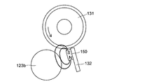
- the toner is stirred and conveyed by the agitating and conveying member 123b in the magnetic field of the magnet 150 arranged on the upstream side (left side in FIG. 7) of the regulating member 132 in the rotation direction of the developing roller 131. Is done.
- the magnetic carriers try to be connected to each other while the toner is moved.
- the magnetic carrier and the toner rub against each other, and the external additive is buried in the toner, or the external additive moves from the toner to the carrier and the toner and the carrier deteriorate. For this reason, image quality deteriorates.
- the present invention has been made to solve the above-described problems, and an object of the present invention is to provide a developing device capable of suppressing the stress on the developer and improving the image quality and the same.
- An image forming apparatus is provided.
- a developing device includes a developing container that contains a developer containing a magnetic carrier and toner, an agitating and conveying member that agitates and conveys the developer in the developing container, and a developer that is supplied from the agitating and conveying member.
- a developer carrying body that supports the developer, a regulating member that is disposed opposite to the developer carrying body and regulates the layer thickness of the developer on the surface of the developer carrying body, and is arranged upstream of the regulating member in the rotation direction of the developer carrying body.
- the magnet magnetized on one side is arranged to face the developer carrier so that the magnetized surface faces the developer carrier.
- FIG. 1 is a cross-sectional view schematically illustrating a structure of an image forming apparatus including a developing device according to an embodiment of the present invention.
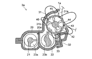
- 1 is a side cross-sectional view illustrating a structure of a developing device according to an embodiment of the present invention.
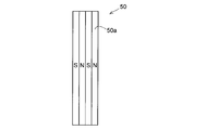
- FIG. 3 is an enlarged cross-sectional view illustrating a structure around a regulation pole and a magnet of a developing device according to an embodiment of the present invention. It is side surface sectional drawing which showed magnetic flux distribution of the magnetic pole of the developing roller of the developing device of one Embodiment of this invention. It is an expanded sectional view for demonstrating the structure of the magnet of the image development apparatus of one Embodiment of this invention.
- the structure of the image forming apparatus 100 including the developing devices 3a to 3d according to the embodiment of the present invention will be described with reference to FIGS.
- the main body of the image forming apparatus 100 here, a color printer
- four image forming portions Pa, Pb, Pc, and Pd are sequentially arranged from the upstream side in the transport direction (right side in FIG. 1).
- These image forming portions Pa to Pd are provided corresponding to images of four different colors (cyan, magenta, yellow, and black), and cyan, magenta, and yellow are respectively performed by charging, exposure, development, and transfer processes. And a black image are sequentially formed.
- image forming portions Pa to Pd are provided with photosensitive drums (image carriers) 1a, 1b, 1c and 1d for carrying visible images (toner images) of the respective colors, and further driving means (FIG. 1), an intermediate transfer belt 8 that rotates clockwise in FIG. 1 is provided adjacent to each of the image forming portions Pa to Pd.
- the toner images formed on the photosensitive drums 1a to 1d are sequentially primary-transferred and superimposed on the intermediate transfer belt 8 that moves while contacting the photosensitive drums 1a to 1d. Thereafter, the toner image primarily transferred onto the intermediate transfer belt 8 is secondarily transferred onto a transfer paper P as an example of a recording medium by the action of the secondary transfer roller 9.
- the transfer paper P on which the toner image is secondarily transferred is discharged from the main body of the image forming apparatus 100 after the toner image is fixed in the fixing unit 13.
- An image forming process for each of the photosensitive drums 1a to 1d is executed while rotating the photosensitive drums 1a to 1d counterclockwise in FIG.
- the transfer paper P on which the toner image is secondarily transferred is housed in a paper cassette 16 disposed at the lower part of the main body of the image forming apparatus 100, and is transferred to the secondary transfer roller via the paper feed roller 12a and the registration roller pair 12b. 9 and a nip portion between a later-described intermediate transfer belt 8 and a driving roller 11.
- a sheet made of dielectric resin is used for the intermediate transfer belt 8, and a (seamless) belt having no seam is mainly used.
- a blade-like belt cleaner 19 for removing toner remaining on the surface of the intermediate transfer belt 8 is disposed on the downstream side of the secondary transfer roller 9.
- the image forming units Pa to Pd There are chargers 2a, 2b, 2c and 2d for charging the photosensitive drums 1a to 1d, and image information on the photosensitive drums 1a to 1d around and below the photosensitive drums 1a to 1d, which are rotatably arranged.
- the exposure device 5 for exposing the toner, the developing devices 3a, 3b, 3c and 3d for forming toner images on the photosensitive drums 1a to 1d, and the developer (toner) remaining on the photosensitive drums 1a to 1d are removed.
- Cleaning parts 7a, 7b, 7c and 7d are provided.
- image data When image data is input from a host device such as a personal computer, first, the surfaces of the photosensitive drums 1a to 1d are uniformly charged by the chargers 2a to 2d, and then light is irradiated according to the image data by the exposure device 5. Then, electrostatic latent images corresponding to the image data are formed on the respective photosensitive drums 1a to 1d.
- Each of the developing devices 3a to 3d is filled with a predetermined amount of a two-component developer containing toners of cyan, magenta, yellow, and black.
- each development from the toner containers (replenishing units) 4a to 4d is performed.
- the toner is supplied to the devices 3a to 3d.
- the toner in the developer is supplied onto the photosensitive drums 1a to 1d by the developing devices 3a to 3d and electrostatically adheres to the electrostatic latent image formed by exposure from the exposure device 5. A toner image is formed.
- the primary transfer rollers 6a to 6d apply an electric field at a predetermined transfer voltage between the primary transfer rollers 6a to 6d and the photosensitive drums 1a to 1d, and cyan, magenta, yellow, and yellow on the photosensitive drums 1a to 1d.
- a black toner image is primarily transferred onto the intermediate transfer belt 8. These four color images are formed with a predetermined positional relationship predetermined for forming a predetermined full-color image. Thereafter, in preparation for the subsequent formation of a new electrostatic latent image, the toner remaining on the surface of the photosensitive drums 1a to 1d after the primary transfer is removed by the cleaning units 7a to 7d.
- the intermediate transfer belt 8 is stretched over an upstream driven roller 10 and a downstream drive roller 11, and the intermediate transfer belt 8 rotates clockwise as the drive roller 11 is rotated by a drive motor (not shown).
- the transfer paper P is conveyed from the registration roller pair 12b to the nip portion (secondary transfer nip portion) between the drive roller 11 and the secondary transfer roller 9 provided adjacent thereto at a predetermined timing.
- the full color image on the intermediate transfer belt 8 is secondarily transferred onto the transfer paper P.
- the transfer sheet P on which the toner image is secondarily transferred is conveyed to the fixing unit 13.
- the transfer paper P conveyed to the fixing unit 13 is heated and pressed by the fixing roller pair 13a to fix the toner image on the surface of the transfer paper P, thereby forming a predetermined full color image.
- the transfer paper P on which the full-color image is formed is distributed in the transport direction by the branching portion 14 that branches in a plurality of directions. When an image is formed on only one side of the transfer paper P, it is discharged as it is onto the discharge tray 17 by the discharge roller pair 15.
- FIG. 2 shows a state viewed from the back side of FIG. 1, and the arrangement of each member in the developing device 3a is opposite to that in FIG.
- the developing device 3a disposed in the image forming unit Pa in FIG. 1 is illustrated, but the configuration of the developing devices 3b to 3d disposed in the image forming units Pb to Pd is basically the same. Therefore, explanation is omitted.
- the developing device 3a includes a resin developing container 20 in which a two-component developer (hereinafter simply referred to as a developer) is accommodated, and the developing container 20 is agitated and conveyed by a partition wall 20a. It is divided into a chamber 21 and a supply transfer chamber 22.
- a agitating / conveying chamber 21 and the supply / conveying chamber 22 an agitating / conveying screw (agitating / conveying member) for mixing the toner (positively charged toner) supplied from the toner container 4a (see FIG. 1) with the carrier, agitating, and charging. ) 23a and a supply conveyance screw (stirring conveyance member) 23b are rotatably arranged.
- the agitating and conveying screw 23a conveys the developer to one side in the axial direction (a direction perpendicular to the paper surface of FIG. 2) of the developing roller 31 described later.
- the supply conveyance screw 23b supplies the developer to the developing roller 31 while conveying the developer in the direction opposite to that of the agitation conveyance screw 23a.
- the ends of the agitating and conveying chamber 21 and the supply and conveying chamber 22 are connected to both ends of the partition wall 20a separating the agitating and conveying chamber 21 and the supply and conveying chamber 22 in the longitudinal direction (the direction perpendicular to the paper surface of FIG. 2).
- Communication portions (not shown) that communicate with each other are provided.
- the developer is agitated by the agitating and conveying screw 23a and the supply and conveying screw 23b while being conveyed in the axial direction (direction perpendicular to the paper surface of FIG. 2), and is agitated via the communication portions formed at both ends of the partition wall 20a. It circulates between the transfer chamber 21 and the supply transfer chamber 22. That is, a developer circulation path is formed in the developing container 20 by the agitating and conveying chamber 21, one communicating portion, the supply conveying chamber 22, and the other communicating portion.
- the developing container 20 extends obliquely upward to the right in FIG. 2, and a developing roller (developer carrying member) 31 is disposed above the supply / conveying screw 23b in the developing container 20.
- the developing roller 31 faces the photosensitive drum 1a on the opening side (the right side in FIG. 2) of the developing container 20, and supplies toner to the photosensitive drum 1a in the facing region.
- the developing roller 31 rotates counterclockwise in the drawing with respect to the rotation axis.
- a toner concentration sensor (not shown) is disposed so as to face the agitating / conveying screw 23a, and agitation is performed from the toner container 4a via a toner supply port (not shown) based on the detection result of the toner concentration sensor.
- the transfer chamber 21 is supplied with toner.
- the toner concentration sensor for example, a magnetic permeability sensor that detects the magnetic permeability of a two-component developer composed of toner and magnetic carrier in the developing container 20 is used.
- the developing roller 31 includes a cylindrical non-magnetic developing sleeve 31a that rotates counterclockwise in FIG. 2 and a fixed magnet body 31b having a plurality of magnetic poles contained in the developing sleeve 31a.
- the magnetic poles of the fixed magnet body 31b are N-pole regulating poles (head cutting magnetic poles) 42, S-pole carrying poles 43, N-pole main poles 44, and S-pole carrying poles 45.
- a separation electrode 46 composed of N poles.
- the regulation electrode 42 is disposed so as to face the ear cutting blade 32 or the magnet 50 described later.
- the magnetic flux distribution of the magnetic poles of the developing roller 31 is formed as shown in FIG.
- the magnetic force of the regulating pole 42 extends to the upstream side in the rotation direction of the developing roller 31 (hereinafter simply referred to as upstream side) with respect to the magnet 50 described later, and the regulating pole 42 is supplied from the supply / conveying screw 23 b to the developing roller 31. It also functions as the top of the pump.
- the magnetic force of the regulation pole 42 is 35 mT, and the magnetic force of the main pole 44 is 100 mT. In FIG. 4, the magnetic flux distribution is drawn with a thick line.
- a spike cutting blade (regulating member) 32 that regulates the thickness of the developer carried on the developing roller 31 extends along the longitudinal direction of the developing roller 31 (direction perpendicular to the paper surface of FIG. 2). Attached.
- the ear cutting blade 32 is positioned upstream of the facing position between the developing roller 31 and the photosensitive drum 1a in the rotation direction of the developing roller 31 (counterclockwise direction in the drawing).
- a slight gap (gap) is formed between the tip of the ear cutting blade 32 and the surface of the developing roller 31.
- the ear cutting blade 32 is made of a magnetic material (SUS430 or the like) and has a thickness of about 1.5 mm.
- the ear cutting blade 32 is fixed to the bottom of the developing container 20.
- a restriction upstream member 33 is disposed on the upstream side of the ear cutting blade 32.
- the restriction upstream member 33 has a pre-regulation function that restricts the thickness of the developer carried on the developing roller 31 to some extent before the ear cutting blade 32 and a stress reduction function that reduces stress on the developer.
- a magnet 50 made of a magnet sheet having a thickness of about 0.6 mm is disposed upstream of the tip of the spike cutting blade 32 (part on the developing roller 31 side).
- the magnet 50 is fixed to the upper surface of the restriction upstream member 33.
- the downstream end of the magnet 50 (the end on the ear cutting blade 32 side) is magnetized to the N pole, so the tip of the ear cutting blade 32 (on the developing roller 31 side).
- An S pole is induced at the end.
- a magnetic field is generated between the tip of the ear cutting blade 32 and the developing sleeve 31a (regulating electrode 42), and the developer passing between the ear cutting blade 32 and the developing roller 31 is regulated to a predetermined layer thickness. Is done.
- the magnetic lines of force of the magnet 50 are drawn with thick lines.
- the developer on the surface of the developing roller 31 is made uniform by the magnetic field between the magnet 50 and the developing roller 31. Thereby, it is possible to suppress the occurrence of density unevenness at the rotation pitch of the supply conveyance screw 23b.
- the magnet 50 is magnetized only on one side (the magnetized surface 50a), and no magnetic field lines are generated from the surface (non-magnetized surface) opposite to the magnetized surface 50a of the magnet 50.
- the magnet 50 is disposed to face the developing roller 31 so that the magnetized surface 50a faces the developing roller 31 side.
- Two sets of N poles and S poles are alternately magnetized on the magnetized surface 50a in a direction along the rotation direction of the developing roller 31 at a pitch of about 2.0 mm.
- the N pole and the S pole are formed so as to extend in the rotation axis direction of the developing roller 31 (the direction perpendicular to the paper surface of FIG. 2, the vertical direction of FIG. 6).
- the magnetic force of the magnetic pole of the magnet 50 is 40 mT. Note that one or more pairs of N and S poles may be magnetized.
- the above-mentioned supply and conveyance screw 23b is disposed in the vicinity of the magnet 50.
- the distance from the magnet 50 to the supply conveyance screw 23b is approximately the same as the distance from the magnet 50 to the regulation electrode 42.
- the vicinity of the magnet 50 refers to a range from the magnet 50 to about the distance L, where L is the distance that the magnetic force of the magnet 50 (for example, the distance from the magnet 50 to the regulation pole 42).
- a direct current voltage hereinafter referred to as Vslv (DC)
- Vslv (AC) an alternating voltage
- DC direct current voltage
- AC alternating voltage
- the toner in the developer is charged by circulating through the agitating and conveying chamber 21 and the supplying and conveying chamber 22 in the developing container 20 while the developer is agitated by the agitating and conveying screw 23a and the supply and conveying screw 23b.
- the developer in the supply conveyance chamber 22 is conveyed to the developing roller 31 by the supply conveyance screw 23b.
- a magnetic brush (not shown) is formed on the developing roller 31.
- the magnetic brush on the developing roller 31 is regulated in layer thickness by the cutting blade 32 and the regulating pole 42, and then conveyed to the opposite portion between the developing roller 31 and the photosensitive drum 1 a by the rotation of the developing roller 31.
- Vslv (DC) and Vslv (AC) are applied to the developing roller 31, the toner flies from the developing roller 31 to the photosensitive drum 1a due to a potential difference between the developing roller 31 and the photosensitive drum 1a.
- the electrostatic latent image is developed.
- the toner remaining without being used for development is conveyed by the rotation of the developing sleeve 31a, and the developer on the surface of the developing sleeve 31a has a magnetic field repelled by the peeling pole 46 and the regulation pole 42 having the same polarity. Therefore, after being peeled off from the developing sleeve 31 a near the middle between the peeling electrode 46 and the regulating electrode 42, it falls into the supply conveyance chamber 22. Then, after being agitated and conveyed by the agitating / conveying screw 23a and the supply / conveying screw 23b, the two-component developer uniformly charged with an appropriate toner concentration is again magnetically applied on the developing sleeve 31a by the pumping pole (regulatory electrode 42). A brush is formed and conveyed to the ear cutting blade 32.
- the magnet 50 is arranged to face the developing roller 31 so that the magnetized surface 50a faces the developing roller 31 side.
- the magnet 50 since it can suppress that a magnetic force line comes out from the surface on the opposite side to the developing roller 31 of the magnet 50, it can prevent that the magnetic field by the magnet 50 is formed in spaces other than the developing roller 31 side of the magnet 50. Can be suppressed.
- the space other than the developing roller 31 side around the magnet 50 it is possible to suppress the magnetic carrier and the toner from rubbing each other and applying stress to the developer, so that the image quality can be improved. Since the magnetic carriers tend to be connected to each other in the magnetic field, when the toner is moved in the magnetic carriers, the magnetic carrier and the toner rub against each other. Then, the external additive is buried in the toner, or the external additive moves from the toner to the carrier and the toner and the carrier are deteriorated, so that the image quality is lowered.
- the supply and conveyance screw 23 b is disposed in the vicinity of the upstream side of the magnet 50.
- a line of magnetic force is generated from the surface of the magnet 50 opposite to the developing roller 31, a magnetic field is also formed in the vicinity of the upstream side of the magnet 50.
- the toner is moved in the magnetic field by the supply / conveyance screw 23b, and the developer is particularly easily stressed. For this reason, it is particularly effective to apply the present invention when the supply and conveyance screw 23b is disposed in the vicinity of the upstream side of the magnet 50.
- a magnetic field by the regulation electrode 42 is formed up to the supply / conveyance screw 23b, and the developer is stressed. It is easy to take. Therefore, it is particularly effective to apply the present invention when the regulation electrode 42 also pumps the developer.
- the magnetic force of the regulation pole 42 extends to the upstream side of the magnet 50. As a result, the developer can be easily pumped from the supply conveying screw 23 b to the developing roller 31 by the regulation electrode 42.
- the present invention is not limited to this.
- the present invention can be applied to various image forming apparatuses having a developing device having a regulating member for regulating the layer thickness of the surface of the developer carrying member, such as a monochrome copying machine, a monochrome printer, a digital multifunction machine, and a facsimile machine. .
- a developing roller is provided as a developer carrying member.
- the present invention is not limited to this, and a magnetic roller as a developer carrying member is provided between the stirring and conveying member and the developing roller. It may be provided.
- the present invention is not limited thereto, and the supply conveyance screw and the regulating member are arranged on the upper side or side of the developing roller. You may arrange in.
- restriction member made of a magnetic material an example in which the restriction member made of a magnetic material is used has been described.
- the present invention is not limited to this, and a restriction member made of a magnet may be used.
Landscapes
- Physics & Mathematics (AREA)
- General Physics & Mathematics (AREA)
- Dry Development In Electrophotography (AREA)
- Magnetic Brush Developing In Electrophotography (AREA)
Abstract
Description
Claims (6)
- 磁性キャリアおよびトナーを含む現像剤を収容する現像容器と、
前記現像容器内の前記現像剤を撹拌搬送する撹拌搬送部材と、
前記撹拌搬送部材から供給される前記現像剤を担持する現像剤担持体と、
前記現像剤担持体に対向配置され、前記現像剤担持体の表面の前記現像剤の層厚を規制する規制部材と、
前記規制部材の前記現像剤担持体回転方向上流側に配置され、S極およびN極が前記現像剤担持体の回転軸方向に延びるように片面着磁された磁石と、
を備え、
前記磁石は、着磁面が前記現像剤担持体側を向くように、前記現像剤担持体に対向配置されることを特徴とする現像装置。 - 前記撹拌搬送部材は、前記磁石の前記現像剤担持体回転方向上流側の近傍に配置されていることを特徴とする請求項1に記載の現像装置。
- 前記現像剤担持体は、前記規制部材または前記磁石に対向配置される規制極を含み、
前記規制極は、前記撹拌搬送部材から前記現像剤担持体への前記現像剤の汲み上げも行うことを特徴とする請求項2に記載の現像装置。 - 前記規制極の磁力は、前記磁石よりも前記現像剤担持体回転方向上流側まで広がっていることを特徴とする請求項3に記載の現像装置。
- 前記磁石の着磁面には、前記現像剤担持体回転方向に沿った方向に、2組以上のS極およびN極が交互に着磁されていることを特徴とする請求項1に記載の現像装置。
- 請求項1に記載の現像装置を備えることを特徴とする画像形成装置。
Priority Applications (3)
| Application Number | Priority Date | Filing Date | Title |
|---|---|---|---|
| US14/892,864 US9360794B2 (en) | 2014-01-15 | 2014-11-10 | Developing device and image forming device provided with same |
| CN201480029263.3A CN105229538B (zh) | 2014-01-15 | 2014-11-10 | 显影装置以及具备该显影装置的图像形成装置 |
| JP2015557718A JP5970620B2 (ja) | 2014-01-15 | 2014-11-10 | 現像装置及びそれを備えた画像形成装置 |
Applications Claiming Priority (2)
| Application Number | Priority Date | Filing Date | Title |
|---|---|---|---|
| JP2014004918 | 2014-01-15 | ||
| JP2014-004918 | 2014-01-15 |
Publications (1)
| Publication Number | Publication Date |
|---|---|
| WO2015107757A1 true WO2015107757A1 (ja) | 2015-07-23 |
Family
ID=53542661
Family Applications (1)
| Application Number | Title | Priority Date | Filing Date |
|---|---|---|---|
| PCT/JP2014/079725 Ceased WO2015107757A1 (ja) | 2014-01-15 | 2014-11-10 | 現像装置及びそれを備えた画像形成装置 |
Country Status (4)
| Country | Link |
|---|---|
| US (1) | US9360794B2 (ja) |
| JP (1) | JP5970620B2 (ja) |
| CN (1) | CN105229538B (ja) |
| WO (1) | WO2015107757A1 (ja) |
Cited By (1)
| Publication number | Priority date | Publication date | Assignee | Title |
|---|---|---|---|---|
| JP2017111360A (ja) * | 2015-12-18 | 2017-06-22 | コニカミノルタ株式会社 | 現像装置および画像形成装置 |
Families Citing this family (1)
| Publication number | Priority date | Publication date | Assignee | Title |
|---|---|---|---|---|
| CN107065478A (zh) * | 2017-05-13 | 2017-08-18 | 中山市奔码打印耗材有限公司 | 一种显影装置 |
Citations (7)
| Publication number | Priority date | Publication date | Assignee | Title |
|---|---|---|---|---|
| JP2000275962A (ja) * | 1999-03-26 | 2000-10-06 | Ricoh Co Ltd | 現像装置 |
| JP2003195641A (ja) * | 2001-12-25 | 2003-07-09 | Canon Inc | 現像装置 |
| JP2005215460A (ja) * | 2004-01-30 | 2005-08-11 | Kyocera Mita Corp | 現像装置 |
| JP2008116685A (ja) * | 2006-11-02 | 2008-05-22 | Canon Inc | 現像装置及び画像形成装置 |
| JP2008185909A (ja) * | 2007-01-31 | 2008-08-14 | Kyocera Mita Corp | 現像装置及び画像形成装置 |
| JP2011158649A (ja) * | 2010-01-29 | 2011-08-18 | Fuji Xerox Co Ltd | 現像装置及び画像形成装置 |
| JP2012185196A (ja) * | 2011-03-03 | 2012-09-27 | Canon Inc | 現像装置及び画像形成装置 |
Family Cites Families (8)
| Publication number | Priority date | Publication date | Assignee | Title |
|---|---|---|---|---|
| US4637706A (en) * | 1983-06-14 | 1987-01-20 | Canon Kabushiki Kaisha | Developer thin layer forming apparatus |
| DE4112429A1 (de) * | 1990-04-27 | 1991-10-31 | Seikosha Kk | Entwicklungsvorrichtung fuer einen elektrofotografischen drucker |
| JPH07152252A (ja) * | 1993-11-29 | 1995-06-16 | Mita Ind Co Ltd | 現像装置 |
| JP3614813B2 (ja) * | 2001-11-30 | 2005-01-26 | 京セラミタ株式会社 | 現像装置及び画像形成装置 |
| JP2003255710A (ja) | 2001-12-28 | 2003-09-10 | Kyocera Mita Corp | 現像装置およびこれを用いた画像形成装置 |
| JP2009300755A (ja) * | 2008-06-13 | 2009-12-24 | Kyocera Mita Corp | 現像装置及び画像形成装置 |
| JP2011112696A (ja) * | 2009-11-24 | 2011-06-09 | Kyocera Mita Corp | 現像装置及びそれを備えた画像形成装置 |
| JP5760496B2 (ja) * | 2011-02-21 | 2015-08-12 | 株式会社リコー | 現像装置、プロセスカートリッジ、及び画像形成装置 |
-
2014
- 2014-11-10 US US14/892,864 patent/US9360794B2/en not_active Expired - Fee Related
- 2014-11-10 WO PCT/JP2014/079725 patent/WO2015107757A1/ja not_active Ceased
- 2014-11-10 JP JP2015557718A patent/JP5970620B2/ja not_active Expired - Fee Related
- 2014-11-10 CN CN201480029263.3A patent/CN105229538B/zh not_active Expired - Fee Related
Patent Citations (7)
| Publication number | Priority date | Publication date | Assignee | Title |
|---|---|---|---|---|
| JP2000275962A (ja) * | 1999-03-26 | 2000-10-06 | Ricoh Co Ltd | 現像装置 |
| JP2003195641A (ja) * | 2001-12-25 | 2003-07-09 | Canon Inc | 現像装置 |
| JP2005215460A (ja) * | 2004-01-30 | 2005-08-11 | Kyocera Mita Corp | 現像装置 |
| JP2008116685A (ja) * | 2006-11-02 | 2008-05-22 | Canon Inc | 現像装置及び画像形成装置 |
| JP2008185909A (ja) * | 2007-01-31 | 2008-08-14 | Kyocera Mita Corp | 現像装置及び画像形成装置 |
| JP2011158649A (ja) * | 2010-01-29 | 2011-08-18 | Fuji Xerox Co Ltd | 現像装置及び画像形成装置 |
| JP2012185196A (ja) * | 2011-03-03 | 2012-09-27 | Canon Inc | 現像装置及び画像形成装置 |
Cited By (1)
| Publication number | Priority date | Publication date | Assignee | Title |
|---|---|---|---|---|
| JP2017111360A (ja) * | 2015-12-18 | 2017-06-22 | コニカミノルタ株式会社 | 現像装置および画像形成装置 |
Also Published As
| Publication number | Publication date |
|---|---|
| CN105229538A (zh) | 2016-01-06 |
| JPWO2015107757A1 (ja) | 2017-03-23 |
| US20160109829A1 (en) | 2016-04-21 |
| US9360794B2 (en) | 2016-06-07 |
| JP5970620B2 (ja) | 2016-08-17 |
| CN105229538B (zh) | 2019-05-28 |
Similar Documents
| Publication | Publication Date | Title |
|---|---|---|
| JP6002698B2 (ja) | 現像装置及びそれを備えた画像形成装置 | |
| JP5642116B2 (ja) | 現像装置及びそれを備えた画像形成装置 | |
| JP2011013248A (ja) | 現像装置及びそれを備えた画像形成装置 | |
| CN106257337A (zh) | 显影装置和具备该显影装置的图像形成装置 | |
| JP5156778B2 (ja) | 現像装置及びそれを備えた画像形成装置 | |
| JP5970620B2 (ja) | 現像装置及びそれを備えた画像形成装置 | |
| CN106257338A (zh) | 显影装置和具备该显影装置的图像形成装置 | |
| JP2005134767A (ja) | 現像装置、プロセスカートリッジ及び画像形成装置 | |
| JP6241437B2 (ja) | 現像装置及びそれを備えた画像形成装置 | |
| JP6057934B2 (ja) | 現像装置、及び現像装置を備えた画像形成装置 | |
| JP6012645B2 (ja) | 現像装置、及び現像装置を備えた画像形成装置 | |
| JP2014153608A (ja) | 現像装置及びそれを備えた画像形成装置 | |
| JP2015152907A (ja) | 現像装置、及び現像装置を備えた画像形成装置 | |
| JP5061209B2 (ja) | 現像装置及びそれを備えた画像形成装置 | |
| JP2011085777A (ja) | 現像装置及びそれを備えた画像形成装置 | |
| JP5634441B2 (ja) | 現像装置及びそれを備えた画像形成装置 | |
| JP6848703B2 (ja) | 現像装置、画像形成装置 | |
| JP2005202242A (ja) | 現像装置、プロセスカートリッジ及び画像形成装置 | |
| JP5674985B2 (ja) | 画像形成装置 | |
| JP5156777B2 (ja) | 現像装置及びそれを備えた画像形成装置 | |
| JP2011150248A (ja) | 現像装置、プロセスカートリッジ、及び画像形成装置 | |
| JP2005215460A (ja) | 現像装置 | |
| JP2011191506A (ja) | 現像装置及びそれを備えた画像形成装置 | |
| JP6428704B2 (ja) | 現像装置、およびこれを備えた画像形成装置 | |
| JP2010054898A (ja) | 画像形成装置 |
Legal Events
| Date | Code | Title | Description |
|---|---|---|---|
| WWE | Wipo information: entry into national phase |
Ref document number: 201480029263.3 Country of ref document: CN |
|
| 121 | Ep: the epo has been informed by wipo that ep was designated in this application |
Ref document number: 14878561 Country of ref document: EP Kind code of ref document: A1 |
|
| ENP | Entry into the national phase |
Ref document number: 2015557718 Country of ref document: JP Kind code of ref document: A |
|
| WWE | Wipo information: entry into national phase |
Ref document number: 14892864 Country of ref document: US |
|
| NENP | Non-entry into the national phase |
Ref country code: DE |
|
| 122 | Ep: pct application non-entry in european phase |
Ref document number: 14878561 Country of ref document: EP Kind code of ref document: A1 |