WO2015105018A1 - Dispositif indicateur pour véhicule - Google Patents
Dispositif indicateur pour véhicule Download PDFInfo
- Publication number
- WO2015105018A1 WO2015105018A1 PCT/JP2014/084465 JP2014084465W WO2015105018A1 WO 2015105018 A1 WO2015105018 A1 WO 2015105018A1 JP 2014084465 W JP2014084465 W JP 2014084465W WO 2015105018 A1 WO2015105018 A1 WO 2015105018A1
- Authority
- WO
- WIPO (PCT)
- Prior art keywords
- display
- torque
- amount
- vehicle
- segment
- Prior art date
Links
- 230000008859 change Effects 0.000 claims description 26
- 238000000034 method Methods 0.000 description 16
- 230000008569 process Effects 0.000 description 13
- 230000000052 comparative effect Effects 0.000 description 6
- 238000010586 diagram Methods 0.000 description 5
- 230000007704 transition Effects 0.000 description 5
- 239000003086 colorant Substances 0.000 description 4
- 239000004973 liquid crystal related substance Substances 0.000 description 4
- 238000005401 electroluminescence Methods 0.000 description 2
- 230000006870 function Effects 0.000 description 2
- 238000005286 illumination Methods 0.000 description 2
- 238000002834 transmittance Methods 0.000 description 2
- 230000008901 benefit Effects 0.000 description 1
Images


Classifications
-
- B—PERFORMING OPERATIONS; TRANSPORTING
- B60—VEHICLES IN GENERAL
- B60K—ARRANGEMENT OR MOUNTING OF PROPULSION UNITS OR OF TRANSMISSIONS IN VEHICLES; ARRANGEMENT OR MOUNTING OF PLURAL DIVERSE PRIME-MOVERS IN VEHICLES; AUXILIARY DRIVES FOR VEHICLES; INSTRUMENTATION OR DASHBOARDS FOR VEHICLES; ARRANGEMENTS IN CONNECTION WITH COOLING, AIR INTAKE, GAS EXHAUST OR FUEL SUPPLY OF PROPULSION UNITS IN VEHICLES
- B60K35/00—Arrangement of adaptations of instruments
-
- B60K35/215—
-
- B60K35/28—
-
- B60K35/60—
-
- G—PHYSICS
- G01—MEASURING; TESTING
- G01D—MEASURING NOT SPECIALLY ADAPTED FOR A SPECIFIC VARIABLE; ARRANGEMENTS FOR MEASURING TWO OR MORE VARIABLES NOT COVERED IN A SINGLE OTHER SUBCLASS; TARIFF METERING APPARATUS; MEASURING OR TESTING NOT OTHERWISE PROVIDED FOR
- G01D7/00—Indicating measured values
- G01D7/02—Indicating value of two or more variables simultaneously
- G01D7/04—Indicating value of two or more variables simultaneously using a separate indicating element for each variable
- G01D7/06—Luminous indications projected on a common screen
-
- B60K2360/167—
Definitions
- the present invention relates to a vehicle display device, and more particularly to a vehicle display device that displays a wheel torque amount.
- a display device that is installed in the vicinity of a speedometer, a tachometer, etc., and graphically displays the magnitude of torque currently distributed to each wheel.
- Patent Document 1 in a four-wheel drive vehicle capable of distributing engine torque to front wheels and rear wheels, the magnitude of torque currently distributed to each wheel is expressed as follows: Techniques for displaying by the number of LED segments that emit light are disclosed.
- Patent Document 1 has a problem that the amount of torque cannot be determined instantaneously.
- the present invention has been made in view of the above problems, and an object of the present invention is to provide a vehicle display device capable of visually and instantaneously grasping the torque state of a wheel and its change state.
- a torque display unit for graphically displaying the amount of torque generated on a drive wheel of a vehicle, which is arranged upward and downward from a predetermined reference unit.
- a display control unit that performs control so that a display segment at a position corresponding to a torque amount is selected and turned on.
- the display segments constituting the display segment group of the torque display unit may be configured such that the display color becomes darker as the amount of change in torque generated in the drive wheels is larger.
- a vehicle display device capable of visually and instantaneously grasping the torque state of a wheel and its change state.
- FIG. 1 is a functional block diagram showing a functional configuration of a vehicle display device 1 according to the present embodiment.
- the vehicle display device 1 includes a torque display unit 100 that graphically displays the amount of torque generated in the drive wheels of a vehicle that can change torque distribution, such as a four-wheel drive vehicle.
- display segment groups 2A and 2B are respectively arranged upward and downward from the reference unit 101 displayed by printing or LEDs.
- the display segment groups 2A and 2B each include a plurality of display segments 3a to 3f and 4a to 4f.
- the display segments 3a to 3f and 4a to 4f at the positions selected by the control of the display control unit 5 are turned on. Note that the number of display segments is not limited to six as shown in FIG. 1, and can be any number.
- the display control unit 5 displays the display segments 3a to 3b at positions corresponding to the torque amount in the display segment group 2A arranged upward from the reference unit 101. 3f is selected and controlled to light up.
- the display segments 4a to 4f at positions corresponding to the torque amount are selected from the display segment group 2B arranged downward from the reference portion 101. And control to light up.
- the display segment groups 2A and 2B can be composed of, for example, a TFT liquid crystal display (TFT-LCD) equipped with a backlight.
- TFT-LCD TFT liquid crystal display
- a configuration example of the display segment groups 2A and 2B using the TFT-LCD will be described later.
- a specific display mode will also be described later.
- the display segment groups 2A and 2B are not limited to TFT type liquid crystal displays, but may be configured by LED displays or surface light emitting devices.
- the display segments 3a to 3f and 4a to 4f constituting the display segment groups 2A and 2B of the torque display unit 100 are configured so that the display color changes according to the amount of change in torque generated in the drive wheels. May be.
- the display segments 3a to 3f and 4a to 4f constituting the display segment groups 2A and 2B of the torque display unit 100 are configured so that the shades of display colors change according to the amount of change in torque generated in the drive wheels. It may be configured.
- the larger the change amount of torque the darker the color and the change amount of torque for the lighting colors of the display segments 3a to 3f or 4a to 4f.
- the smaller the value the lighter the color can be changed.
- FIG. 2 is a circuit diagram showing an example of a circuit configuration of the vehicle display device 1 according to the present embodiment.
- the vehicle display device 1 includes a display panel 11, a graphic controller 13, a CPU 15, and various I / O interfaces 17 and 18 connected to the CPU 15, which constitute a part of the meter panel of the vehicle.
- the display panel 11 comprises display segment groups 2A and 2B shown in FIG. 1, and is composed of a color TFT liquid crystal panel (TFT-LCD) that performs graphic display.
- TFT-LCD color TFT liquid crystal panel
- the graphic controller 13, the X driver 21, the Y driver 23, and the CPU 15 constitute a display control unit 5.
- the display panel 11 is driven by an X driver 21 that applies a voltage according to a horizontal synchronizing signal and a Y driver 23 that applies a voltage according to a vertical synchronizing signal.
- the display panel 11 is provided with a backlight 11a (illumination unit) whose illuminance is adjusted by an applied voltage from the LCD power supply 28.
- a backlight 11a for example, LED (Light-Emitting-Diode) or EL (Electro-Luminescence) illumination can be used.
- LED Light-Emitting-Diode
- EL Electro-Luminescence
- the graphic controller 13 has a frame memory 13a for storing various image data such as RGB image data of the display segment.
- the graphic controller 13 transmits the image data stored in the frame memory 13a to the display panel 11. Further, the graphic controller 13 outputs a horizontal synchronization signal to the X driver 21 and outputs a vertical synchronization signal to the Y driver 23.
- the graphic controller 13 adjusts the LCD transmittance and chromaticity by changing the value of the image data in accordance with an instruction from the CPU 15, and displays the display segments 3a to 3f and 4a displayed on the display panel 11 at the time of lighting at night. Adjust the display of ⁇ 4f.
- the LCD transmittance and chromaticity By using the LCD transmittance and chromaticity, the display color and shading of each display segment can be easily adjusted.
- the EEPROM 15 is externally attached to the CPU 15.
- the CPU 15 executes a display control program stored in the EEPROM 25, generates image data such as display segments 3a to 3e and 4a to 4e displayed on the display panel 11, and transmits them to the graphic controller 13.
- the ignition switch (IGN) 52 connected to the plus (+) of the battery (power source) 51 is connected to the I / O interface 17 and ON / OFF of the ignition switch 52 is input.
- torque data and the like are input to the I / O interface 18.
- power is supplied to the CPU 15 from a CPU power source 27 connected to the battery 51.
- power is supplied to the display panel 11 from the LCD power source 28 connected to the battery 51.
- the LCD power supply 28 applies a voltage to each electrode of the TFT liquid crystal 11 and also applies a voltage to the backlight 11a.
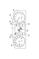
- FIG. 3 is a plan view illustrating a configuration example of an instrument panel 200 that includes the vehicle display device 1 according to the present embodiment and is disposed in front of a driver's seat of a vehicle such as an automobile.
- the vehicle display device 1 In the instrument panel 200 shown in FIG. 3, the vehicle display device 1 according to the present embodiment is disposed at the center, a circular speedometer (speedometer) 201 is disposed on the left side, and a circular tachometer is disposed on the right side. A (tachometer) 202 is arranged. Further, a turn L display unit 203, a turn R display unit 204, and the like are arranged.
- the vehicle display device 1 shown in FIG. 3 has a yaw moment display unit 300 indicating the state of the yaw moment of the vehicle at the center, and a display segment group 2A indicating the torque distribution state on the left and right of the yaw moment display unit 300. (2A1, 2A2), 2B (2B1, 2B2) are arranged.
- FIG 3 shows a state where the display segment 3a of the upper left display segment group 2A1 and the display segment 3b of the upper right display segment group 2A2 are lit.
- lighting modes (lighting patterns) of the display segments 3a to 3f and 4a to 4f in the display segment groups 2A (2A1, 2A2) and 2B (2B1, 2B2) will be described.
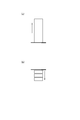
- FIG. 4A shows a transition state of the lighting positions of the display segments 3a to 3f in the display segment group 2A (2A1, 2A2).
- One display segment 3a-3f at a position corresponding to the quantity is selected and lit. In this case, as the amount of torque increases, the display segments 3a to 3f positioned in the upward direction are selected and turned on.
- the change amount V1 of the display segment 3a ⁇ 3b, the change amount V2 of the display segment 3a ⁇ 3c, the change amount V3 of the display segment 3a ⁇ 3d, and the change amount of the display segment 3a ⁇ 3e is V1 ⁇ V2 ⁇ V3 ⁇ V4 ⁇ V5.
- the display colors of the display segments 3b to 3f are changed so as to become darker as the change amounts V1 to V5 are larger. That is, as the amount of change in torque increases from 3b ⁇ 3c ⁇ 3d ⁇ 3e ⁇ 3f, for example, the display color is changed so as to gradually darken, such as light blue ⁇ blue ⁇ dark blue.
- the lighting color may be changed from a red system or the like to a cold system color such as a blue system or a green system in a gradation according to the amount of change in torque generated in the drive wheels.
- FIG. 4B shows a transition state of the lighting positions of the display segments 4a to 4f in the display segment group 2B (2B1, 2B2).
- One display segment 4a-4f at a position corresponding to the quantity is selected and lit.
- the display segments 4a to 4f positioned in the downward direction are selected and lighted as the minus amount of the torque amount increases.
- the change amount V1 of the display segment 4a ⁇ 4b, the change amount V2 of the display segment 4a ⁇ 4c, the change amount V3 of the display segment 4a ⁇ 4d, and the change amount of the display segment 4a ⁇ 4e is V1 ⁇ V2 ⁇ V3 ⁇ V4 ⁇ V5.
- the display colors of the display segments 4b to 4f are changed to become darker as the change amounts V1 to V5 are larger. That is, as the amount of change in torque increases from 4b ⁇ 4c ⁇ 4d ⁇ 4e ⁇ 4f, the display color is changed to gradually darken, for example, light red ⁇ red ⁇ dark red.
- the lighting color may be changed in gradation from a blue system or the like to an emphasized color (or warm color system) such as a red system or an orange system according to the amount of change in torque generated in the drive wheels.
- FIG. 5 is an explanatory diagram showing a display example of torque and the like in the vehicle display device 1 according to the present embodiment.
- FIG. 5A is a display example of torque and the like when the vehicle C is traveling straight in the direction D1, as illustrated on the right side.
- the torque generated on the left wheel and the right wheel on the left and right of the moment display unit 300 indicating the state of the moment is the display segment 3b of the display segment group 2A1 on the drive side and the drive side. Is displayed by lighting the display segment 3b of the display segment group 2A2. That is, the torque difference between the left and right wheels when the vehicle C is traveling straight in the direction D1 is “0”, so the display mode is as described above.
- FIG. 5B is a display example of a torque amount or the like when a counterclockwise moment (in the direction of the arrow M1) is generated in the vehicle C as illustrated on the right side.
- the torques generated on the left and right wheels on the left and right of the moment display section 300 indicating the state of the moment are the display segment 4d of the display segment group 2B1 on the braking side and the braking side. Is displayed by lighting the display segment 4b of the display segment group 2B2. That is, for example, when the vehicle C is turning to the right while applying a brake, the braking force of the left wheel is greater than the braking force of the right wheel, so the display mode is as described above.
- FIG. 5C is a display example of the torque amount and the like when a clockwise (in the direction of arrow M2) moment is generated in the vehicle C, as shown on the right side.
- the torque generated on the left wheel and the right wheel on the left and right of the moment display section 300 indicating the state of the moment is the display segment 3a of the display segment group 2A1 on the driving side and the braking side. Is displayed by lighting the display segment 3b of the display segment group 2A2. That is, for example, when the vehicle C is turning right with the accelerator on, the torque of the left wheel is greater than the torque of the right wheel, so the display mode is as described above.
- the lighting positions of the display segments 3a to 3f and 4a to 4f in the display segment groups 2A (2A1, 2A2) and 2B (2B1, 2B2) transition in a straight line in the vertical direction.
- the present invention is not limited to this, and the lighting position may transition along an arc or a predetermined curve.
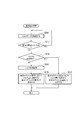
- This display control process is performed for each drive wheel (for example, left and right drive wheels in the case of two-wheel drive, and each drive wheel in the case of four-wheel drive).
- step S10 torque data is acquired from a predetermined sensor or the like provided in the vehicle, and the process proceeds to step S11.
- step S11 it is determined whether or not the vehicle is stopped based on the torque data. If “Yes”, the process returns to step S10, and if “No”, the process proceeds to step S12.
- step S12 it is determined whether or not the torque is on the drive side. If “Yes”, the process proceeds to step S13, and the position of the display segment group 2A (2A1, 2A2) on the drive side corresponds to the torque amount.
- the display segments 3a to 3f are selected and turned on, and the process ends.
- step S12 the process proceeds to step S14, and the process proceeds to step S15 assuming that the torque is on the braking side.
- step S15 in the display segment group 2B (2B1, 2B2) on the braking side, the display segments 4a to 4f at positions corresponding to the torque amount are selected and turned on, and the process is terminated.
- the torque amount is represented by a display area like a bar graph.
- the torque amount is represented by the number of display segments to be lit.
- the driver of the vehicle needs to recognize the area and the number of display segments in order to grasp the torque amount, and it takes some time to grasp the torque amount.
- the vehicle display device 1 as shown in FIG. 5, only the display segment corresponding to the peak position of the torque amount is lit, so that the driver of the vehicle There is an advantage that the amount can be grasped instantly. Further, when the color and density of the display segment are changed depending on the position of the display segment, it is further easy to grasp the torque amount.
- the vehicle display device of the present invention has been described based on the illustrated embodiment, but the present invention is not limited to this, and the configuration of each part is replaced with an arbitrary configuration having the same function. be able to.
Abstract
L'invention concerne un dispositif indicateur pour un véhicule équipé d'une unité d'indication de couple (100) qui indique de manière graphique une quantité du couple généré dans les roues motrices du véhicule. L'unité d'indication de couple est équipée de groupes de segments indicateurs (2A, 2B) qui sont agencés au-dessus et en dessous d'une partie de référence prédéterminée, et seul un segment indicateur disposé au niveau d'une position sélectionnée sous le contrôle d'une unité de commande d'indicateur (5) est allumé. Quand la quantité du couple généré dans les roues motrices est positive, l'unité de commande d'indicateur (5) sélectionne et allume un segment indicateur (3a-3f) qui correspond à la quantité de couple en provenance du groupe de segments indicateurs se trouvant au-dessus de la partie de référence prédéterminée (101). Quand la quantité du couple généré dans les roues motrices est négative, l'unité de commande d'indicateur (5) sélectionne et allume un segment indicateur (4a-4f) qui correspond à la quantité de couple en provenance du groupe de segments indicateurs se trouvant en dessous de la partie de référence prédéterminée.
Applications Claiming Priority (2)
| Application Number | Priority Date | Filing Date | Title |
|---|---|---|---|
| JP2014-002212 | 2014-01-09 | ||
| JP2014002212A JP2015129728A (ja) | 2014-01-09 | 2014-01-09 | 車両用表示装置 |
Publications (1)
| Publication Number | Publication Date |
|---|---|
| WO2015105018A1 true WO2015105018A1 (fr) | 2015-07-16 |
Family
ID=53523852
Family Applications (1)
| Application Number | Title | Priority Date | Filing Date |
|---|---|---|---|
| PCT/JP2014/084465 WO2015105018A1 (fr) | 2014-01-09 | 2014-12-26 | Dispositif indicateur pour véhicule |
Country Status (2)
| Country | Link |
|---|---|
| JP (1) | JP2015129728A (fr) |
| WO (1) | WO2015105018A1 (fr) |
Citations (7)
| Publication number | Priority date | Publication date | Assignee | Title |
|---|---|---|---|---|
| JPS6262215U (fr) * | 1985-10-08 | 1987-04-17 | ||
| JPS63189886A (ja) * | 1987-02-02 | 1988-08-05 | 株式会社日立製作所 | カラ−液晶表示装置 |
| JP2000136946A (ja) * | 1998-11-02 | 2000-05-16 | Harness Syst Tech Res Ltd | 車載用表示装置 |
| JP2005022627A (ja) * | 2003-06-10 | 2005-01-27 | Nissan Motor Co Ltd | 車両用運転操作補助装置および車両用運転操作補助装置を備えた車両 |
| JP2011046362A (ja) * | 2009-08-28 | 2011-03-10 | Honda Motor Co Ltd | 車両用トルク表示装置 |
| WO2011108091A1 (fr) * | 2010-03-03 | 2011-09-09 | 株式会社 東芝 | Dispositif d'affichage embarqué dans un véhicule et procédé d'affichage |
| JP2012026759A (ja) * | 2010-07-20 | 2012-02-09 | Nippon Seiki Co Ltd | 車両用計器の照明装置 |
-
2014
- 2014-01-09 JP JP2014002212A patent/JP2015129728A/ja not_active Abandoned
- 2014-12-26 WO PCT/JP2014/084465 patent/WO2015105018A1/fr active Application Filing
Patent Citations (7)
| Publication number | Priority date | Publication date | Assignee | Title |
|---|---|---|---|---|
| JPS6262215U (fr) * | 1985-10-08 | 1987-04-17 | ||
| JPS63189886A (ja) * | 1987-02-02 | 1988-08-05 | 株式会社日立製作所 | カラ−液晶表示装置 |
| JP2000136946A (ja) * | 1998-11-02 | 2000-05-16 | Harness Syst Tech Res Ltd | 車載用表示装置 |
| JP2005022627A (ja) * | 2003-06-10 | 2005-01-27 | Nissan Motor Co Ltd | 車両用運転操作補助装置および車両用運転操作補助装置を備えた車両 |
| JP2011046362A (ja) * | 2009-08-28 | 2011-03-10 | Honda Motor Co Ltd | 車両用トルク表示装置 |
| WO2011108091A1 (fr) * | 2010-03-03 | 2011-09-09 | 株式会社 東芝 | Dispositif d'affichage embarqué dans un véhicule et procédé d'affichage |
| JP2012026759A (ja) * | 2010-07-20 | 2012-02-09 | Nippon Seiki Co Ltd | 車両用計器の照明装置 |
Also Published As
| Publication number | Publication date |
|---|---|
| JP2015129728A (ja) | 2015-07-16 |
Similar Documents
| Publication | Publication Date | Title |
|---|---|---|
| US7750821B1 (en) | System and method for instrument panel with color graphical display | |
| JP4229923B2 (ja) | 表示装置、インストルメントパネル、自動車両およびインストルメントパネルの制御方法 | |
| US20080185976A1 (en) | Display backlight system and method | |
| RU2010103674A (ru) | Способ и система для управления фоновой подсветкой в дисплее | |
| US9649977B2 (en) | LED driver for vehicle display illumination | |
| EP1843319A2 (fr) | Appareil d'affichage à cristaux liquides | |
| US11170722B2 (en) | Display device with a backlight | |
| CN109986964B (zh) | 仪表显示装置 | |
| JP5909329B2 (ja) | 車両用表示装置 | |
| JP2017174091A (ja) | 覚醒維持装置及び覚醒維持方法 | |
| JP2008191248A (ja) | 液晶ディスプレイ用バックライト装置 | |
| WO2015105018A1 (fr) | Dispositif indicateur pour véhicule | |
| CN201476808U (zh) | 仪表指针显色装置 | |
| CN109291850B (zh) | 车辆用灯具 | |
| WO2015105020A1 (fr) | Dispositif d'affichage destiné à être utilisé dans un véhicule | |
| CN109442342A (zh) | 车辆用灯具 | |
| JP5982848B2 (ja) | 車両用表示装置 | |
| CN109386811B (zh) | 车辆用灯具 | |
| JP2017140983A (ja) | 車両用表示装置 | |
| JP4966093B2 (ja) | 作業車輌 | |
| KR200394195Y1 (ko) | 차량용 후방보조지시램프 | |
| JP2010197828A (ja) | フィールドシーケンシャル画像表示装置 | |
| JP2019028102A (ja) | 画像表示装置および画像表示方法 | |
| JP2018159743A (ja) | 画像表示装置および画像表示装置の制御方法 | |
| KR101851320B1 (ko) | 점멸 신호등 및 그 제어방법 |
Legal Events
| Date | Code | Title | Description |
|---|---|---|---|
| 121 | Ep: the epo has been informed by wipo that ep was designated in this application |
Ref document number: 14877850 Country of ref document: EP Kind code of ref document: A1 |
|
| NENP | Non-entry into the national phase |
Ref country code: DE |
|
| 122 | Ep: pct application non-entry in european phase |
Ref document number: 14877850 Country of ref document: EP Kind code of ref document: A1 |