WO2015104773A1 - 入力装置 - Google Patents
入力装置 Download PDFInfo
- Publication number
- WO2015104773A1 WO2015104773A1 PCT/JP2014/006414 JP2014006414W WO2015104773A1 WO 2015104773 A1 WO2015104773 A1 WO 2015104773A1 JP 2014006414 W JP2014006414 W JP 2014006414W WO 2015104773 A1 WO2015104773 A1 WO 2015104773A1
- Authority
- WO
- WIPO (PCT)
- Prior art keywords
- force
- input
- magnetic
- input device
- adjustment structure
- Prior art date
- Legal status (The legal status is an assumption and is not a legal conclusion. Google has not performed a legal analysis and makes no representation as to the accuracy of the status listed.)
- Ceased
Links
Images


Classifications
-
- G—PHYSICS
- G06—COMPUTING OR CALCULATING; COUNTING
- G06F—ELECTRIC DIGITAL DATA PROCESSING
- G06F3/00—Input arrangements for transferring data to be processed into a form capable of being handled by the computer; Output arrangements for transferring data from processing unit to output unit, e.g. interface arrangements
- G06F3/01—Input arrangements or combined input and output arrangements for interaction between user and computer
- G06F3/016—Input arrangements with force or tactile feedback as computer generated output to the user
-
- G—PHYSICS
- G06—COMPUTING OR CALCULATING; COUNTING
- G06F—ELECTRIC DIGITAL DATA PROCESSING
- G06F3/00—Input arrangements for transferring data to be processed into a form capable of being handled by the computer; Output arrangements for transferring data from processing unit to output unit, e.g. interface arrangements
- G06F3/01—Input arrangements or combined input and output arrangements for interaction between user and computer
-
- G—PHYSICS
- G06—COMPUTING OR CALCULATING; COUNTING
- G06F—ELECTRIC DIGITAL DATA PROCESSING
- G06F3/00—Input arrangements for transferring data to be processed into a form capable of being handled by the computer; Output arrangements for transferring data from processing unit to output unit, e.g. interface arrangements
- G06F3/01—Input arrangements or combined input and output arrangements for interaction between user and computer
- G06F3/02—Input arrangements using manually operated switches, e.g. using keyboards or dials
- G06F3/0202—Constructional details or processes of manufacture of the input device
-
- G—PHYSICS
- G06—COMPUTING OR CALCULATING; COUNTING
- G06F—ELECTRIC DIGITAL DATA PROCESSING
- G06F3/00—Input arrangements for transferring data to be processed into a form capable of being handled by the computer; Output arrangements for transferring data from processing unit to output unit, e.g. interface arrangements
- G06F3/01—Input arrangements or combined input and output arrangements for interaction between user and computer
- G06F3/03—Arrangements for converting the position or the displacement of a member into a coded form
- G06F3/033—Pointing devices displaced or positioned by the user, e.g. mice, trackballs, pens or joysticks; Accessories therefor
- G06F3/0354—Pointing devices displaced or positioned by the user, e.g. mice, trackballs, pens or joysticks; Accessories therefor with detection of two-dimensional [2D] relative movements between the device, or an operating part thereof, and a plane or surface, e.g. 2D mice, trackballs, pens or pucks
-
- G—PHYSICS
- G06—COMPUTING OR CALCULATING; COUNTING
- G06F—ELECTRIC DIGITAL DATA PROCESSING
- G06F3/00—Input arrangements for transferring data to be processed into a form capable of being handled by the computer; Output arrangements for transferring data from processing unit to output unit, e.g. interface arrangements
- G06F3/01—Input arrangements or combined input and output arrangements for interaction between user and computer
- G06F3/03—Arrangements for converting the position or the displacement of a member into a coded form
- G06F3/033—Pointing devices displaced or positioned by the user, e.g. mice, trackballs, pens or joysticks; Accessories therefor
- G06F3/0362—Pointing devices displaced or positioned by the user, e.g. mice, trackballs, pens or joysticks; Accessories therefor with detection of one-dimensional [1D] translations or rotations of an operating part of the device, e.g. scroll wheels, sliders, knobs, rollers or belts
-
- G—PHYSICS
- G06—COMPUTING OR CALCULATING; COUNTING
- G06F—ELECTRIC DIGITAL DATA PROCESSING
- G06F2203/00—Indexing scheme relating to G06F3/00 - G06F3/048
- G06F2203/01—Indexing scheme relating to G06F3/01
- G06F2203/015—Force feedback applied to a joystick
Definitions
- This disclosure relates to an input device to which an operating force is input.
- Patent Document 1 discloses a configuration of an input device that includes a tactile sense providing member to which an operating force is input and includes an actuator that is supported so that the tactile sense presenting member can be moved by the input of the operating force.
- the actuator disclosed in Patent Document 1 is provided with a magnet that forms a magnetic pole, a coil that passes a magnetic flux generated by the magnet, and two yoke plates that guide the magnetic flux generated by the magnet to the coil. The actuator allows the operator to transmit information through a tactile sensation by causing an electromagnetic force generated by the current to the coil to act on the operator as an operation reaction force via the tactile sense providing member.
- the weight of a tactile display member or the like that is movably provided is increased or decreased due to a change in the requirements such as the design and the strength of an operation reaction force that accompanies a specification change. Can do. Then, the pressing force acting on a member such as a housing that supports the tactile sensation presentation member also changes from the tactile sensation presentation member. As a result, for example, if the weight of the tactile sensation presenting member becomes lighter than an appropriate range, rattling and vibration due to insufficient load may occur in the tactile sensation presenting member. Further, if the weight of the tactile presentation member or the like becomes heavier than the appropriate range, an excessive increase in the frictional resistance acting on the tactile presentation member may be caused.
- the force acting between the input unit and the support unit cannot be arbitrarily adjusted, and thus it is not possible to optimize the frictional resistance and the like caused by the movement of the input unit. Therefore, when the weight of the movable part in the input device changes, the operational feeling of the operation for moving the tactile presentation member is impaired.
- An object of the present disclosure is to provide an input device capable of improving the operational feeling of an operation of moving an input unit such as a tactile presentation member.
- the input device includes an input unit, a support unit, a reaction force generation unit, and an adjustment structure.
- the input unit receives an operation force in a direction along the operation plane.
- the support portion supports the input portion so as to be movable along the operation plane by inputting the operation force.
- the reaction force generating unit includes a magnetic pole forming unit that forms a magnetic pole, a coil unit through which a magnetic flux generated by the magnetic pole forming unit passes, and a magnetic flux guiding unit that guides the generated magnetic flux of the magnetic pole forming unit to the coil unit, An electromagnetic force generated by applying a current to the coil unit is applied to the input unit as an operation reaction force in a direction along the operation plane.
- the adjustment structure increases or decreases a pressing force that pushes the support portion in a direction in which the input portion intersects the operation plane by adjusting a total magnetic attraction force that the magnetic pole forming portion attracts the magnetic flux guiding portion.
- the inventor of the present disclosure newly paid attention to the magnetic attractive force generated between the magnetic pole forming portion and the magnetic flux guiding portion, and provided the adjustment structure for adjusting the magnetic attractive force in the input device.
- the adjustment structure adjusts the sum of the magnetic attractive forces between the magnetic pole forming portion and the magnetic flux guiding portion, and increases or decreases the pressing force between the input portion and the support portion. Therefore, the frictional resistance between the input part and the support part that increase or decrease in accordance with the pressing force can be arbitrarily adjusted by the adjustment mechanism. As described above, since the frictional resistance caused by the movement of the input unit can be optimized, it is possible to improve the operational feeling of the operation of moving the input unit by the input of the operating force.
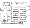
- FIG. 1 is a diagram for describing a configuration of a display system including an operation input device according to the first embodiment of the present disclosure.
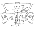
- FIG. 2 is a diagram for explaining the arrangement of the operation input device in the passenger compartment.
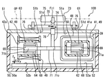
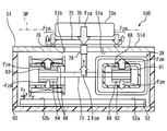
- FIG. 3 is a cross-sectional view for explaining the mechanical configuration of the operation input device.
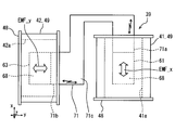
- FIG. 4 is a plan view of the reaction force generator.
- FIG. 5 is a diagram for explaining a mechanism in which the pressing force is reduced by the adjustment structure in a specification including a large operation knob.
- FIG. 6 is a diagram for explaining a mechanism in which the pressing force is increased by the adjustment structure in a specification including a small operation knob.
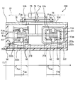
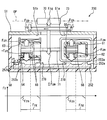
- FIG. 7 is a cross-sectional view for explaining the mechanical configuration of the operation input device according to the second embodiment.
- FIG. 8 is a diagram for explaining a mechanism by which the adjustment structure according to the second embodiment increases the downward magnetic attraction force in the outer edge region of the movable range.
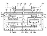
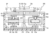
- FIG. 9 is a cross-sectional view for explaining the mechanical configuration of the operation input device according to the third embodiment.
- FIG. 10 is a diagram for explaining a mechanism in which the pressing force is reduced by the adjustment structure in a specification including a large operation knob.
- FIG. 11 is a diagram for explaining a mechanism in which the pressing force is increased by the adjustment structure in a specification including a small operation knob.
- An operation input device 100 according to the first embodiment of the present disclosure shown in FIG. 1 is mounted on a vehicle and installed in a vehicle interior, for example, a vehicle-mounted display device such as a navigation device 20 or a head-up display device 120 (see FIG. 2). And the like constitute the display system 10.
- the operation input device 100 is installed at a position adjacent to the palm rest 19 at the center console of the vehicle, and exposes the operation knob 73 in a range that can be easily reached by the operator.
- the operation knob 73 is displaced in the direction of the input operation force when the operation force is input by the operator's hand H or the like.
- the navigation device 20 is installed in the instrument panel of the vehicle and exposes the display screen 22 toward the driver's seat.
- the display screen 22 displays a plurality of icons associated with a predetermined function, a pointer 80 for selecting an arbitrary icon, and the like.
- the pointer 80 moves on the display screen 22 in a direction corresponding to the input direction of the operation force.
- the navigation device 20 is connected to a communication bus 90 and is capable of network communication with the operation input device 100 and the like.
- the navigation device 20 includes a display control unit 23 that draws an image displayed on the display screen 22 and a liquid crystal display 21 that continuously displays the image drawn by the display control unit 23 on the display screen 22.
- the operation input device 100 is connected to a communication bus 90, an external battery 95, and the like.
- the operation input device 100 can communicate with the navigation device 20 located remotely through the communication bus 90. Further, the operation input device 100 is supplied with electric power necessary for the operation of each component from the battery 95.
- the operation input device 100 is electrically configured by a communication control unit 35, an operation detection unit 31, a reaction force generation unit 39, a reaction force control unit 37, an operation control unit 33, and the like.
- the communication control unit 35 outputs the information processed by the operation control unit 33 to the communication bus 90. In addition, the communication control unit 35 acquires information output from another in-vehicle device to the communication bus 90 and outputs the information to the operation control unit 33.
- the operation detection unit 31 detects the position of the operation knob 73 (see FIG. 2) moved by the input of the operation force. The operation detection unit 31 outputs operation information indicating the detected position of the operation knob 73 to the operation control unit 33.
- the reaction force generating unit 39 is configured to generate an operation reaction force on the operation knob 73 (see FIG. 2), and includes an actuator such as a voice coil motor. For example, when the pointer 80 (see FIG. 2) overlaps the icon on the display screen 22, the reaction force generation unit 39 applies an operation reaction force to the operation knob 73, so that a pseudo icon is generated by so-called reaction force feedback. The tactile sensation is caused to the operator.
- the reaction force control unit 37 is configured by, for example, a microcomputer for performing various calculations. The reaction force control unit 37 controls the direction and strength of the operation reaction force applied from the reaction force generation unit 39 to the operation knob 73 based on the reaction force information acquired from the operation control unit 33.
- the operation control unit 33 is configured by, for example, a microcomputer for performing various calculations.
- the operation control unit 33 acquires operation information detected by the operation detection unit 31 and outputs the operation information to the communication bus 90 through the communication control unit 35.
- the operation control unit 33 calculates the direction and strength of the operation reaction force applied to the operation knob 73 (see FIG. 2), and outputs the calculation result to the reaction force control unit 37 as reaction force information.
- the operation input device 100 is mechanically configured by a movable portion 70, a fixed portion 50, and the like.
- the movable unit 70 moves along the operation plane OP when an operation force in the x-axis direction and the y-axis direction along the virtual operation plane OP is input to the operation knob 73.
- the movable unit 70 returns to the reference position serving as a reference.
- the movable portion 70 has a movable range that is movable in the x-axis direction and the y-axis direction defined in advance by the fixed portion 50.
- the movable portion 70 includes a knob base 74, a slider 75, and the above-described operation knob 73.
- the knob base 74 extends from the operation knob 73 along the z axis perpendicular to the operation plane OP, and an inner yoke 71 described later is provided. keeping.
- “orthogonal” includes not only strictly orthogonal but also substantially orthogonal.
- the slider 75 is provided on the knob base 74 and is formed in a flat plate shape along the operation plane OP.
- the slider 75 is provided with a plurality of sliding projections 76 projecting in a hemispherical shape toward the fixed portion 50.
- the slider 75 is placed on the fixed portion 50 with the top of each sliding protrusion 76 in contact with the surface of the fixed portion 50.
- the slider 75 moves while sliding the sliding protrusions 76 with respect to the fixed portion 50 in response to the input of the operating force to the operating force.
- the fixing unit 50 includes a circuit board and a housing 50a that accommodates the circuit board and the like. Two outer yokes 51 and 52 to be described later are fixed to the fixing portion 50. On the circuit board, a microcomputer constituting the operation control unit 33 and the reaction force control unit 37 (both see FIG. 1) and the like are mounted. The housing 50a supports the movable part 70 so that relative movement is possible.
- the reaction force generation unit 39 functions as an actuator that generates electromagnetic forces EMF_x and EMF_y in each direction along the operation plane OP by a configuration including two voice coil motors.
- the reaction force generating unit 39 includes two coils 41 and 42, four magnets 61 to 64, an inner yoke 71, two outer yokes 51 and 52, and the like.
- the coils 41 and 42 are formed by winding a wire rod made of a non-magnetic material such as copper around a flat cylindrical bobbin 48 as a winding 49.
- the cross section orthogonal to the winding axis direction of the winding 49 is formed in a rectangular shape.
- Each winding 49 is wound until the thickness of the cylindrical wall of each coil 41, 42 is about 3 mm, for example.
- accommodation chambers 41 a, 42 a extending in the winding axis direction are formed on the inner peripheral side of the bobbin 48 and the winding 49.
- Each of the coils 41 and 42 is electrically connected to the reaction force control unit 37 (see FIG. 1) through a wiring pattern provided on the circuit board. A current is individually applied to each winding 49 by the reaction force control unit 37.
- the two coils 41 and 42 are arranged along the y-axis while leaving a slight gap therebetween.
- Each of the coils 41 and 42 is fixed to the fixed portion 50 so that the winding axis direction of the winding 49 is along the operation plane OP.
- the winding axis direction of one coil (hereinafter “first coil”) 41 is along the x-axis.
- the winding axis direction of the other coil (hereinafter “second coil”) 42 is along the y-axis.
- the side surfaces of the coils 41 and 42 are formed in a substantially quadrilateral shape with each side along the x-axis or the y-axis.
- the magnets 61 to 64 are neodymium magnets or the like, and are formed in a substantially quadrangular plate shape having a longitudinal direction. Each of the magnets 61 to 64 is provided with a mounting surface 69 and a magnetized surface 68 formed in a smooth flat shape. Each attachment surface 69 is attached to the inner yoke 71 with the long side oriented along the y-axis.
- the two magnets 61 and 62 are accommodated in the accommodating chamber 41a of the first coil 41, and are arranged so as to sandwich the inner yoke 71 from both sides in the z-axis direction.
- the magnets 61 and 62 are arranged in the z-axis direction orthogonal to the operation plane OP so that the magnetized surfaces 68 are along the operation plane OP.
- the magnetized surfaces 68 of the magnets 61 and 62 held by the inner yoke 71 face different directions in the z-axis direction.
- Each magnetized surface 68 is opposed to the inner peripheral surface of the first coil 41 with a predetermined interval in the z-axis direction.
- the magnetic poles formed on the magnetized surfaces 68 of the magnets 61 and 62 are the same.
- the other two magnets 63 and 64 are accommodated in the accommodating chamber 42a of the second coil 42, and are arranged so as to sandwich the inner yoke 71 from both sides in the z-axis direction.
- the magnets 63 and 64 are arranged in the z-axis direction so that the magnetized surfaces 68 are along the operation plane OP.
- the magnetized surfaces 68 of the magnets 63 and 64 held by the inner yoke 71 face different directions in the z-axis direction.
- Each magnetized surface 68 faces the inner peripheral surface of the second coil 42 with a predetermined interval in the z-axis direction.
- the magnetic poles formed on the magnetized surfaces 68 of the magnets 63 and 64 are the same as each other, and are different from the magnetic poles of the magnetized surfaces 68 of the magnets 61 and 62.
- the inner yoke 71 is made of a magnetic material such as soft iron and electromagnetic steel plate.
- the inner yoke 71 is disposed between the two outer yokes 51 and 52.
- the inner yoke 71 is suspended by a knob base 74 while being separated from the coils 41 and 42.
- the inner yoke 71 is provided with two magnet side yoke portions 71a and 71b formed in a flat plate shape, and a connecting portion 71c for connecting the magnet side yoke portions 71a and 71b to each other.
- first magnet side yoke part (hereinafter referred to as “first magnet side yoke part”) 71 a is inserted into the accommodating chamber 41 a of the first coil 41.
- the attachment surfaces 69 of the magnets 61 and 62 are attached to both surfaces of the first magnet side yoke portion 71a accommodated in the accommodation chamber 41a.
- the other magnet side yoke part (hereinafter, “second magnet side yoke part”) 71 b is inserted into the accommodation chamber 42 a of the second coil 42.
- the attachment surfaces 69 of the magnets 63 and 64 are respectively attached to both surfaces of the second magnet side yoke portion 71b accommodated in the accommodation chamber 42a.
- the connecting portion 71 c is bent in an L shape along the coils 41 and 42.
- a gap corresponding to the maximum stroke amount of the operation knob 73 is provided between the connecting portion 71 c and the coils 41 and 42.
- the outer yokes 51 and 52 are formed of a magnetic material such as soft iron and an electromagnetic steel plate, like the inner yoke 71. Each of the outer yokes 51 and 52 is formed in a rectangular shape. The outer yokes 51 and 52 are located on both sides of the two coils 41 and 42 in the z-axis direction, and are opposed to each other so as to sandwich the coils 41 and 42.
- upper outer yoke 51 is fixed to the housing 50a as a lid of the housing 50a.
- the upper outer yoke 51 is formed with a first facing surface 51a, a second facing surface 51b, an opening 51c, and a sliding surface 51d.
- the first facing surface 51 a and the second facing surface 51 b are formed on one surface of the upper outer yoke 51 facing the coils 41 and 42.
- the first facing surface 51 a faces the magnetized surface 68 of the magnet 61 and is positioned so as to sandwich the first coil 41 from both the inside and outside with the magnetized surface 68.
- the second facing surface 51 b faces the magnetized surface 68 of the magnet 62 and is positioned so as to sandwich the second coil 42 from both the inside and outside with the magnetized surface 68.
- the opening 51c is provided in the central portion of the upper outer yoke 51 and penetrates the upper outer yoke 51 in the plate thickness direction.
- the opening 51 c passes a knob base 74 extending from the operation knob 73 toward the inner yoke 71.
- the sliding surface 51d is formed on the other surface of the upper outer yoke 51 facing the operation knob 73 side.
- the sliding surface 51d is formed in a planar shape along the operation plane OP.
- a slider 75 is placed on the sliding surface 51d.
- the sliding surface 51d supports a plurality of sliding protrusions 76 so as to be slidable.
- the lower outer yoke 52 forms a first facing surface 52a and a second facing surface 52b.
- the first facing surface 52 a and the second facing surface 52 b are formed on one surface of the lower outer yoke 52 facing the coils 41 and 42.
- the first facing surface 52a faces the magnetized surface 68 of the magnet 62, and is positioned so as to sandwich the first coil 41 from both the inside and outside with the magnetized surface 68.
- the second facing surface 52b faces the magnetized surface 68 of the magnet 64, and is positioned so as to sandwich the second coil 42 from both inside and outside with the magnetized surface 68.
- the above inner yoke 71 and the two outer yokes 51 and 52 form a magnetic circuit for guiding the magnetic flux generated by each of the magnets 61 to 64 to each of the coils 41 and 42.
- the magnetic flux generated by the two magnets 61 and 62 penetrates (passes) the winding 49 of the first coil 41 in the z-axis direction, and passes from the first opposing surfaces 51a and 52a to the outer yokes 51. , 52 and toward the second opposing surfaces 51b, 52b.
- the magnetic flux generated by the two magnets 63 and 64 passes through (passes) the winding 49 of the second coil 42 in the z-axis direction from the second facing surfaces 51b and 52b, while the second magnet side yoke portion. Enter 71b. And magnetic flux goes to the 1st magnet side yoke part 71a, passing the connection part 71c in the inner yoke 71.
- FIG. As described above, by forming a magnetic circuit across the two voice coil motors, the density of the magnetic flux penetrating through the winding 49 of each coil is increased.
- an electromagnetic force EMF_x in the x-axis direction is generated between the first coil 41 and the magnets 61 and 62 by applying a current to the first coil 41.
- application of current to the second coil 42 generates an electromagnetic force EMF_y in the y-axis direction between the second coil 42 and the magnets 63 and 64.
- the directions of the electromagnetic forces EMF_x and EMF_y are reversed by reversing the direction of the current applied to the coils 41 and 42.
- the strength of each electromagnetic force EMF_x, EMF_y can be controlled by adjusting the magnitude of the current applied to each coil 41, 42.
- the adjustment structure 78 can adjust the length in the z-axis direction from the slider 75 to the inner yoke 71.
- the adjustment structure 78 has an expansion / contraction mechanism that expands / contracts the knob base 74, and can arbitrarily define the position of the inner yoke 71 in the z-axis direction.
- the adjustment structure 78 enables adjustment of the frictional resistance generated between each sliding protrusion 76 and the sliding surface 51d when the movable part 70 is moved by adjusting the position of the inner yoke 71 in the z-axis direction. .
- the principle will be described below with reference to FIGS.
- Each of the magnets 61 to 64 generates a magnetic attraction force that attracts one of the opposing surfaces of the first opposing surfaces 51a and 52a and the second opposing surfaces 51b and 52b. Therefore, the inner yoke 71 holding the magnets 61 to 64 has a downward magnetic attraction force ⁇ Fzm toward the lower outer yoke 52 along the z axis and an upward force toward the upper outer yoke 51 along the z axis.
- the magnetic attractive force Fzm is acting.
- the distance between the magnets 61 and 63 and the upper outer yoke 51 is the distance between the magnets 62 and 64 and the lower outer yoke 52. Shorter than the distance.
- the upward magnetic attractive force Fzm is reduced to the downward magnetic attractive force. It becomes larger than -Fzm. Accordingly, the sum of the magnetic attractive forces Fzm (see ⁇ Fzm in FIG.
- the weights of the operation knobs are different.
- the operation knob 73a shown in FIG. 5 is larger and heavier than the standard operation knob 73 (see FIG. 1). Therefore, the load Fzg acting on the slider 75 from the operation knob 73a becomes larger than the load Fzg acting on the slider 75 from the standard operation knob 73a. Therefore, by adjusting the position of the inner yoke 71 by the adjustment structure 78 described above, the sum of the magnetic attractive forces Fzm is set as an upward force.
- the pressing force Fzp that the movable part 70 pushes the sliding surface 51d downward through the sliding protrusions 76 of the slider 75 is reduced by the force of the sum of the magnetic attractive forces Fzm.
- the frictional resistance generated between the sliding protrusions 76 and the sliding surface 51d can be adjusted considerably by the function of the adjusting structure 78 when the standard operation knob 73 is provided.
- the operation knob 73b shown in FIG. 6 is smaller and lighter than the standard operation knob 73 (see FIG. 1). Therefore, the load Fzg acting on the slider 75 from the operation knob 73b is smaller than the load Fzg acting on the slider 75 from the standard operation knob 73. Therefore, by adjusting the position of the inner yoke 71 by the adjustment structure 78 described above, the sum of the magnetic attractive forces Fzm is set as a downward force. As a result, the pressing force Fzp that the movable part 70 pushes the sliding surface 51d downward through the sliding protrusions 76 of the slider 75 is enhanced by the force of the sum of the magnetic attractive forces Fzm. As a result, the frictional resistance generated between the sliding protrusions 76 and the sliding surface 51d can be adjusted considerably by the function of the adjusting structure 78 when the standard operation knob 73 is provided.
- the adjustment structure 78 adjusts the total magnetic attraction force Fzm, whereby the pressing force Fzp acting on the fixed portion 50 from the movable portion 70 is increased or decreased. Therefore, the frictional resistance between the movable portion 70 and the fixed portion 50 that increase or decrease corresponding to the pressing force Fzp can be arbitrarily adjusted by the adjustment structure 78.
- the adjustment structure 78 adjusts the frictional resistance caused by the movement of the movable portion 70, it is possible to improve the operational feeling of the operation of moving the operation knob 73 by the input of the operation force.
- preload is applied to the slider 75 by optimizing the pressing force Fzp. Therefore, it is possible to avoid a situation in which each sliding protrusion 76 of the slider 75 floats with respect to the sliding surface 51d due to external vibration or the like.
- the position of the inner yoke 71 adjusted by the adjustment structure 78 in the z-axis direction can be maintained even when the movable unit 70 moves. Therefore, the adjustment structure 78 can adjust the magnetic attractive force Fzm over the entire movable range of the movable portion 70.
- the pressing force Fzp acting on the sliding surface 51d from each sliding projection 76 is within an appropriate range. Can fit in. Therefore, the effect of improving the operational feeling of the operation of moving the movable part 70 is exhibited over the entire movable range.
- the magnetized surfaces 68 of the two magnets 61 and 62 are individually opposed to the first facing surfaces 51a and 52a. Similarly, the magnetized surfaces 68 of the two magnets 63 and 64 individually face the second facing surfaces 51b and 52b. Therefore, the magnetic attraction force Fzm by the magnets 61 and 63 and the magnetic attraction force -Fzm by the magnets 62 and 64 act in the opposite directions along the z axis.
- the relative positions of the magnets 61 to 64 with respect to the outer yokes 51 and 52 are moved along the z-axis so that the magnetized surfaces 68 and the opposing surfaces 51a, 52a, 51b, and 52b
- the total sum of the magnetic attraction forces Fzm can be adjusted by changing each distance.
- the increase / decrease of the pressing force Fzp by adjusting the direction and the magnitude of each magnetic attractive force Fzm can be realized by the adjustment structure 78 having a simple configuration called an expansion / contraction mechanism.
- the upper outer yoke 51 also serves as a part of the fixed portion 50, and the movable portion 70 is supported by a sliding surface 51 d provided on the upper outer yoke 51. According to such a configuration, since the number of parts of the operation input device 100 can be reduced, greening is realized during the configuration. Further, the operation input device 100 can be thinned.
- the operation input device 100 corresponds to an “input device”
- the movable portion 70 corresponds to an “input portion”
- the fixed portion 50 corresponds to a “support portion”.
- the magnets 61 to 64 correspond to the “magnetic pole forming portion”
- the first coil 41 and the second coil 42 correspond to the “coil portion”
- the reaction force generating portion 39 corresponds to the “reaction force generating portion”.
- the upper outer yoke 51 and the lower outer yoke 52 correspond to “magnetic flux guiding portions”
- the first facing surfaces 51a and 52a and the second facing surfaces 51b and 52b correspond to “facing surfaces”.
- the second embodiment of the present disclosure shown in FIGS. 7 and 8 is an embodiment different from the first embodiment.
- the first opposing surface 252a and the second opposing surface 252b formed on the lower outer yoke 252 are configured to also serve as the adjustment structure 278.
- the adjustment structure 278 according to the second embodiment will be described.
- convex surfaces 253a and 253b are provided on the opposing surfaces 252a and 252b of the lower outer yoke 252, respectively.
- Each of the convex surface portions 253 a and 253 b has a shape protruding from the reference surface 252 c of the lower outer yoke 252 toward the magnetized surface 68 in the z-axis direction.
- the convex surface portion 253a extends in a rectangular ring shape so as to face the magnetized surface 68 of the magnet 62 that has moved to the maximum in the x-axis direction and the y-axis direction in the z-axis direction.
- the convex surface portion 253b extends in a rectangular ring shape so as to oppose the magnetized surface 68 of the magnet 64 that has moved to the maximum in the x-axis direction and the y-axis direction in the z-axis direction.
- the above adjustment structure 278 can increase or decrease the total sum of the magnetic attractive force Fzm according to the movement position of the movable part 70 moved along the operation plane OP. Specifically, the adjustment structure is such that the pressing force Fzp by the movable portion 70 located in the outer edge region of the movable range is larger than the pressing force Fzp by the movable portion 70 (see FIG. 7) located in the central region of the movable range. 278 can adjust the sum of the magnetic attractive force Fzm. The principle and effect will be described below.
- the movable part 70 presses each sliding protrusion 76 of the slider 75 against the sliding surface 51d by the load Fzg due to its own weight.
- the distance between the magnetized surfaces 68 of the two magnets 61 and 63 and the opposing surfaces 51a and 51b of the upper outer yoke 51 is maintained even when the operation knob 73 is stroked. Therefore, the upward magnetic attractive force Fzm acting on the magnets 61 and 63 is substantially constant. As a result, the sum of the magnetic attractive forces Fzm acts downward on the inner yoke 71 (see ⁇ Fzm in FIG. 8). Due to the change in the sum of the magnetic attraction forces Fzm, the pressing force Fzp is increased in the outer edge region of the movable range defined by the movable portion 70. Therefore, a braking force due to an increase in frictional resistance can be applied to the movable portion 70 that has moved to the outer edge region.
- the pressing force Fzp between the movable portion 70 and the fixed portion 50 is increased or decreased by adjusting the sum of the magnetic attractive force Fzm by the adjustment structure 278.
- the frictional resistance caused by the movement of the movable portion 70 can be arbitrarily adjusted and can be optimized, thereby improving the operational feeling of operating the operation knob.
- a braking force can be applied to the movable portion 70 that has moved to the outer edge region of the movable range. Due to the braking action caused by such frictional resistance, it is possible to avoid damage to the operation input device 200 due to the collision of the movable part 70 with the part of the fixed part 50 that restricts the movable range.
- the adjustment structure 278 that exhibits the braking action in the outer edge region can be realized by a simple configuration of forming the convex surface portions 253a and 253b.
- the operation input device 200 corresponds to an “input device”. Further, the lower outer yoke 252 and the upper outer yoke 51 correspond to the “magnetic flux guiding portion”, and the opposing surfaces 252a and 252b correspond to the “facing surface” together with the opposing surfaces 51a and 51b.
- the third embodiment of the present disclosure shown in FIGS. 9 to 11 is a modification of the first embodiment.
- the magnets 61 to 64 are arranged on the outer peripheral side of the coils 41 and 42.
- the reaction force generation unit 339 includes an inner yoke 371, an upper outer yoke 351, and a lower outer yoke 352 corresponding to the yokes 71, 51, 52 (see FIG. 3) of the first embodiment.
- the inner yoke 371 shown in FIG. 9 holds the coils 41 and 42.
- the inner yoke 371 includes a first coil side yoke portion 371a accommodated in the accommodation chamber 41a, a second coil side yoke portion 371b accommodated in the accommodation chamber 42a, and a connecting portion for connecting the coil side yoke portions 371a and 371b. 371c is provided.
- On both surfaces of the first coil side yoke portion 371a a pair of first opposing surfaces 371d that oppose each magnetized surface 68 of each magnet 61, 62 in the z-axis direction are formed.
- On both surfaces of the second coil side yoke portion 371b a pair of second opposing surfaces 371e that oppose each magnetized surface 68 of each magnet 63, 64 in the z-axis direction are formed.
- the attachment surfaces 69 of the two magnets 61 and 63 are attached to both ends of the upper outer yoke 351 in the longitudinal direction. As a result, the upper outer yoke 351 holds the magnets 61 and 63.
- the upper outer yoke 351 is accommodated in the housing 350a. From the upper outer yoke 351, a portion corresponding to the sliding surface 51d (see FIG. 3) of the first embodiment is omitted. In the third embodiment, a sliding surface 351d that slidably supports the movable portion 370 is formed on the upper surface of the housing 350a.
- the attachment surfaces 69 of the two magnets 62 and 64 are attached to both ends of the lower outer yoke 352 in the longitudinal direction. As a result, the lower outer yoke 352 holds the magnets 62 and 64.
- the lower outer yoke 352 is attached to the knob base 374 together with the upper outer yoke 351, and is movable along the operation plane OP.
- the operation input device 300 described above is provided with an adjustment structure 378 that is substantially the same as the adjustment structure 78 (see FIG. 3) of the first embodiment.
- the adjustment structure 378 As shown in FIG. 10, when the position of each outer yoke 351, 352 is brought closer to the operation knob 73 a by the adjustment structure 378, the distance between the magnets 62, 64 and the inner yoke 371 is changed between the magnets 61, 63 and the inner yoke 371. It becomes shorter than the distance. For this reason, the upward magnetic attractive force Fzm is larger than the downward magnetic attractive force -Fzm. Therefore, the sum of the magnetic attractive forces Fzm (see ⁇ Fzm in FIG. 10) is an upward force.
- the pressing force Fzp that the movable part 370 pushes the sliding surface 351d downward through each sliding projection 76 of the slider 75 is the magnetic attraction force Fzm. Reduced by the power of the sum. As a result, the frictional resistance generated between each sliding protrusion 76 and the sliding surface 351d can be adjusted considerably by the function of the adjusting structure 378 when the standard operation knob 73 (see FIG. 9) is provided.
- the pressing force Fzp that the movable portion 370 pushes the sliding surface 351d downward through each sliding protrusion 76 of the slider 75 is the magnetic attraction force Fzm. It is enhanced by the power of the sum. As a result, the frictional resistance generated between each sliding protrusion 76 and the sliding surface 351d can be adjusted considerably by the function of the adjusting structure 378 when the standard operation knob 73 (see FIG. 9) is provided.
- the frictional resistance between the movable portion 370 and the fixed portion 350 can be arbitrarily adjusted by the adjustment structure 378 as in the first embodiment. Therefore, it is possible to improve the operational feeling of the operation of moving the operation knob 73. Such an effect of improving the operational feeling is also exhibited in the configuration in which the magnets 61 to 64 are disposed on the outer peripheral side of the coils 41 and 42.
- the operation input device 300 corresponds to an “input device”
- the movable portion 370 corresponds to an “input portion”
- the fixed portion 350 corresponds to a “support portion”.
- the reaction force generation unit 339 corresponds to a “reaction force generation unit”.
- the inner yoke 371 corresponds to a “magnetic flux guiding portion”
- the first facing surface 371d and the second facing surface 371e correspond to a “facing surface”.
- the operation input device includes a lower outer yoke 252 of the second embodiment shown in FIG. 7 instead of the lower outer yoke 52 (see FIG. 3). Therefore, the adjustment structure of the first modification includes the convex surface portions 253a and 253b together with the expansion / contraction mechanism. As described above, the adjustment structure provided in the operation input device may be a combination of a plurality of configurations such as an expansion / contraction mechanism and a convex surface portion.
- each magnet is attached to the movable part and is movable.
- each coil may be sufficient as the structure attached to a movable part.
- the four magnets are attached to the inner yoke and are accommodated in the accommodation chambers of the coils.
- the two coils are sandwiched by two outer yokes suspended from the knob base, and can be moved together with the movable portion.
- an adjustment structure for adjusting the positions of the outer yoke and the coil can be provided.
- the electromagnetic forces EMF_x and EMF_y that can be generated by applying a current to each coil increase or decrease according to the movement position of the input unit, and specifically, the outer edge of the movable range. It decreases as it goes to the area. This is because the density of the magnetic flux penetrating the coil decreases due to the relative movement of the coil and the magnet. Therefore, in Modification 3 of the second embodiment, a convex surface portion that also serves as an adjustment structure is provided in the upper outer yoke.
- the convex surface portion has a configuration corresponding to the convex surface portions 253a and 253b (see FIG. 7) provided in the lower outer yoke 252 in the second embodiment.
- the adjustment structure according to the modified example 3 adjusts the sum of the magnetic attractive forces so that the pressing force Fzp becomes weaker toward the moving position where the electromagnetic force that can be generated by the reaction force generator becomes weak, that is, the outer edge region.
- the frictional resistance acting on the movable portion is also weakened, so that the operation reaction force is easily transmitted from the movable portion to the operator. Therefore, it is possible to make it difficult for the operator to increase or decrease the electromagnetic force linked to the moving position of the movable part.
- the pressing force Fzp at an arbitrary position coordinate is increased or decreased by a predetermined amount by adjusting the position of the inner yoke or each outer yoke in the z-axis direction.
- Such increase / decrease of the pressing force Fzp is not limited to the above-described position adjustment.
- the angle (inclination posture) of the magnet with respect to the opposing surface of the yoke, the change in the thickness of the yoke as in the second embodiment, the yoke and the magnet It can also be realized by adjusting the amount of lap, changing the material of the yoke, or the like.
- the display system includes the head-up display device 120 shown in FIG. 2 instead of the navigation device or together with the navigation device.
- the head-up display device 120 is accommodated in the instrument panel of the vehicle in front of the driver seat, and projects an image toward the projection area 122 defined in the window shield, thereby displaying a virtual image of the image. I do.
- An operator sitting in the driver's seat can visually recognize a plurality of icons associated with a predetermined function, a pointer 80 for selecting an arbitrary icon, and the like through the projection area 122.
- the pointer 80 can be moved in the projection area 122 in the direction corresponding to the input direction of the operation force by the horizontal operation input to the operation knob 73 as in the case where it is displayed on the display screen 22.
- the telescopic mechanism has a telescopic structure that is telescopic in the axial direction by inserting one of two cylindrical members having similar cross sections into the other.
- the telescopic mechanism can position the inner yoke at an arbitrary height in the z-axis direction by screwing or caulking of the screw.
- the reaction force generating portion of the above embodiment is formed by combining two voice coil motors.
- the number of voice coil motors provided in the reaction force generation unit may be one or three or more.
- a configuration corresponding to one “magnetic pole forming portion” may be formed by combining a plurality of magnets.
- a magnetic pole may be directly magnetized in either the inner yoke or the outer yoke.
- the present disclosure can be applied to a selector such as a shift lever installed in the center console, a steering switch provided in the steering, and the like.
- the present disclosure can also be applied to various vehicle functional operation devices provided in the vicinity of an instrument panel, an armrest provided on a door or the like, and a rear seat.
- the operation input device to which the present disclosure is applied can be applied not only to the vehicle but also to the entire operation system used for various transportation devices and various information terminals.
Landscapes
- Engineering & Computer Science (AREA)
- General Engineering & Computer Science (AREA)
- Theoretical Computer Science (AREA)
- Human Computer Interaction (AREA)
- Physics & Mathematics (AREA)
- General Physics & Mathematics (AREA)
- User Interface Of Digital Computer (AREA)
- Mechanical Control Devices (AREA)
- Position Input By Displaying (AREA)
Abstract
入力装置は、入力部(70,370)と、支持部(50,350)と、反力発生部(39,339)と、調整構造(78,278,378)とを備える。前記反力発生部は、磁極形成部(61~64)、コイル部(41,42)、及び磁束誘導部(51,52,252,371)を有し、前記コイル部への電流の印加によって生じる電磁力(EMF_x,EMF_y)を、前記操作平面に沿う方向への操作反力として前記入力部に作用させる。前記調整構造は、前記磁極形成部が前記磁束誘導部を引き寄せる磁気吸引力(Fzm)の総和を調整することにより、前記入力部が前記操作平面と交差する方向に前記支持部を押す押圧力(Fzp)を増減させる。
Description
本開示は、2014年1月9日に出願された日本出願番号2014-2702号に基づくもので、ここにその記載内容を援用する。
本開示は、操作力が入力される入力装置に関する。
特許文献1は、操作力が入力される触覚呈示部材を備え、この触覚呈示部材が操作力の入力によって移動可能なよう支持されたアクチュエータを含む入力装置の構成を開示している。この特許文献1に開示のアクチュエータには、磁極を形成する磁石、磁石の発生磁束を通過させるコイル、及び磁石の発生磁束をコイルに誘導する二枚のヨーク板が設けられている。アクチュエータは、コイルへの電流によって生じる電磁力を、触覚呈示部材を介し操作反力として操作者に作用させることにより、操作者への触覚を通した情報伝達を可能にしている。
特許文献1に開示されたような入力装置では、例えばデザイン及び操作反力の強さ等の要求が仕様変更に伴って変化することにより、移動可能に設けられた触覚呈示部材等の重量が増減し得る。すると、触覚呈示部材から、当該触覚呈示部材を支持する筐体等の部材に作用する押圧力も、変化することとなる。その結果、例えば触覚呈示部材等の重量が適切な範囲よりも軽くなってしまうと、荷重不足に起因したガタつき及び振動等が触覚呈示部材に生じ得る。また、触覚呈示部材等の重量が適切な範囲よりも重くなってしまうと、触覚呈示部材に作用する摩擦抵抗の過度な増加が引き起こされる可能性がある。
以上説明したように、従来の構成では、入力部及び支持部の間に作用する力を任意に調整できないため、入力部の移動に伴い生じる摩擦抵抗等を最適化することができなかった。そのため、入力装置における可動部分の重量変化が生じた場合等に、触覚呈示部材を移動させる操作の操作感が、損なわれてしまうのである。
本開示の目的は、触覚呈示部材等の入力部を移動させる操作の操作感の向上が可能な入力装置を提供することである。
本開示の一態様に係る入力装置は、入力部と、支持部と、反力発生部と、調整構造とを備える。前記入力部は、操作平面に沿う方向の操作力が入力される。前記支持部は、前記操作力の入力により前記操作平面に沿って移動可能なよう前記入力部を支持する。前記反力発生部は、磁極を形成する磁極形成部、前記磁極形成部の発生磁束が通過するコイル部、及び前記磁極形成部の発生磁束を前記コイル部に誘導する磁束誘導部を有し、前記コイル部への電流の印加によって生じる電磁力を、前記操作平面に沿う方向への操作反力として前記入力部に作用させる。前記調整構造は、前記磁極形成部が前記磁束誘導部を引き寄せる磁気吸引力の総和を調整することにより、前記入力部が前記操作平面と交差する方向に前記支持部を押す押圧力を増減させる。
本開示の発明者は、前記磁極形成部及び前記磁束誘導部の間にて生じる前記磁気吸引力に新たに着目し、前記磁気吸引力を調整する前記調整構造を、前記入力装置に設けた。前記調整構造によって、前記磁極形成部及び前記磁束誘導部の間における前記磁気吸引力の総和が調整され、前記入力部及び前記支持部の間での前記押圧力が増減される。故に、前記押圧力に対応して増減する前記入力部及び前記支持部の間の摩擦抵抗は、前記調整機構によって任意に調整可能となる。このように、前記入力部の移動に伴い生じる摩擦抵抗が最適化され得るため、前記操作力の入力により前記入力部を移動させる操作の操作感向上が実現可能となる。
本開示における上記あるいは他の目的、構成、利点は、下記の図面を参照しながら、以下の詳細説明から、より明白となる。図面において、
図1は、本開示の第一実施形態による操作入力装置を備えた表示システムの構成を説明するための図である。
図2は、操作入力装置の車室内での配置を説明するための図である。
図3は、操作入力装置の機械的構成を説明するための断面図である。
図4は、反力発生部の平面図である。
図5は、大型の操作ノブを備える仕様において、押圧力が調整構造によって低減される仕組みを説明するための図である。
図6は、小型の操作ノブを備える仕様において、押圧力が調整構造によって増強される仕組みを説明するための図である。
図7は、第二実施形態による操作入力装置の機械的構成を説明するための断面図である。
図8は、第二実施形態による調整構造が、可動範囲の外縁領域にて下向きの磁気吸引力を増加させる仕組みを説明するための図である。
図9は、第三実施形態による操作入力装置の機械的構成を説明するための断面図である。
図10は、大型の操作ノブを備える仕様において、押圧力が調整構造によって低減される仕組みを説明するための図である。
図11は、小型の操作ノブを備える仕様において、押圧力が調整構造によって増強される仕組みを説明するための図である。
以下、本開示の複数の実施形態を図面に基づいて説明する。尚、各実施形態において対応する構成要素には同一の符号を付すことにより、重複する説明を省略する場合がある。各実施形態において構成の一部分のみを説明している場合、当該構成の他の部分については、先行して説明した他の実施形態の構成を適用することができる。また、各実施形態の説明において明示している構成の組み合わせばかりではなく、特に組み合わせに支障が生じなければ、明示していなくても複数の実施形態の構成同士を部分的に組み合わせることができる。そして、複数の実施形態及び変形例に記述された構成同士の明示されていない組み合わせも、以下の説明によって開示されているものとする。
(第一実施形態)
図1に示す本開示の第一実施形態による操作入力装置100は、車両に搭載され、車室内に設けられた車載用の表示器、例えばナビゲーション装置20又はヘッドアップディスプレイ装置120(図2参照)等と共に表示システム10を構成している。操作入力装置100は、図2に示されるように、車両のセンターコンソールにてパームレスト19と隣接する位置に設置され、操作者の手の届き易い範囲に操作ノブ73を露出させている。この操作ノブ73は、操作者の手H等によって操作力が入力されると、入力された操作力の方向に変位する。
図1に示す本開示の第一実施形態による操作入力装置100は、車両に搭載され、車室内に設けられた車載用の表示器、例えばナビゲーション装置20又はヘッドアップディスプレイ装置120(図2参照)等と共に表示システム10を構成している。操作入力装置100は、図2に示されるように、車両のセンターコンソールにてパームレスト19と隣接する位置に設置され、操作者の手の届き易い範囲に操作ノブ73を露出させている。この操作ノブ73は、操作者の手H等によって操作力が入力されると、入力された操作力の方向に変位する。
ナビゲーション装置20は、車両のインスツルメントパネル内に設置され、運転席に向けて表示画面22を露出させている。表示画面22には、所定の機能が関連付けられた複数のアイコン、及び任意のアイコンを選択するためのポインタ80等が表示されている。操作ノブ73に水平方向の操作力が入力されると、ポインタ80は、操作力の入力方向に対応した方向に、表示画面22上を移動する。ナビゲーション装置20は、図1及び図2に示されるように、通信バス90と接続され、操作入力装置100等とネットワーク通信可能である。ナビゲーション装置20は、表示画面22に表示される画像を描画する表示制御部23、及び表示制御部23によって描画された画像を表示画面22に連続的に表示する液晶ディスプレイ21を有している。
操作入力装置100は、図1に示すように、通信バス90及び外部のバッテリ95等と接続されている。操作入力装置100は、離れて位置するナビゲーション装置20と、通信バス90を通じて通信可能とされている。また操作入力装置100は、各構成の作動に必要な電力を、バッテリ95から供給される。
操作入力装置100は、通信制御部35、操作検出部31、反力発生部39、反力制御部37、及び操作制御部33等によって電気的に構成されている。
通信制御部35は、操作制御部33によって処理された情報を通信バス90に出力する。加えて通信制御部35は、他の車載装置から通信バス90に出力された情報を取得し、操作制御部33に出力する。操作検出部31は、操作力の入力によって移動した操作ノブ73(図2参照)の位置を検出する。操作検出部31は、検出した操作ノブ73の位置を示す操作情報を、操作制御部33に出力する。
反力発生部39は、操作ノブ73(図2参照)に操作反力を生じさせる構成であって、ボイスコイルモータ等のアクチュエータを含んでいる。反力発生部39は、例えば表示画面22上においてポインタ80(図2参照)がアイコンと重なる際に、操作反力を操作ノブ73に印加することで、所謂反力フィードバックにより、擬似的なアイコンの触感を操作者に惹起させる。反力制御部37は、例えば種々の演算を行うためのマイクロコンピュータ等によって構成されている。反力制御部37は、操作制御部33から取得する反力情報に基づいて、反力発生部39から操作ノブ73に印加される操作反力の方向及び強さを制御する。
操作制御部33は、例えば種々の演算を行うためのマイクロコンピュータ等によって構成されている。操作制御部33は、操作検出部31によって検出された操作情報を取得し、通信制御部35を通じて通信バス90に出力する。加えて操作制御部33は、操作ノブ73(図2参照)に印加する操作反力の方向及び強さを演算し、演算結果を反力情報として反力制御部37に出力する。
操作入力装置100は、図3に示すように、可動部70及び固定部50等によって機械的に構成されている。
可動部70は、仮想の操作平面OPに沿うx軸方向及びy軸方向の操作力が操作ノブ73に入力されることにより、当該操作平面OPに沿って移動する。そして、印加されていた操作力から解放されると、可動部70は、基準となる基準位置に帰着する。可動部70は、x軸方向及びy軸方向のそれぞれに移動可能な可動範囲を、固定部50によって予め規定されている。
可動部70は、ノブベース74、スライダ75、及び上述の操作ノブ73を有しているノブベース74は、操作平面OPと直交するz軸に沿って操作ノブ73から延伸し、後述するインナーヨーク71を保持している。本開示において、「直交」は厳密な直交だけでなく、実質的な直交も含む。スライダ75は、ノブベース74に設けられ、操作平面OPに沿った平板状に形成されている。スライダ75には、固定部50に向けて半球状に突出する摺動突起76が複数設けられている。スライダ75は、各摺動突起76の頂部を固定部50の表面に接触させつつ、当該固定部50に載置されている。スライダ75は、操作力への操作力の入力により、各摺動突起76を固定部50に対して滑らせつつ移動する。
固定部50は、回路基板、及び回路基板等を収容するハウジング50aを有している。固定部50には、後述する二つのアウターヨーク51,52が固定されている。回路基板には、操作制御部33及び反力制御部37(共に図1参照)等を構成するマイクロコンピュータ等が実装されている。ハウジング50aは、可動部70を相対移動可能に支持している。
以上の可動部70及び固定部50間において、図3及び図4に示す反力発生部39が反力フィードバックを実施する。反力発生部39は、二つのボイスコイルモータを含む構成により、操作平面OPに沿う各方向への電磁力EMF_x,EMF_yを発生させるアクチュエータとして機能する。反力発生部39は、二つのコイル41,42、四つの磁石61~64、インナーヨーク71、及び二つのアウターヨーク51,52等によって構成されている。
各コイル41,42は、銅等の非磁性材料よりなる線材を巻線49として、扁平筒状のボビン48に巻回しすることで形成されている。各コイル41,42において、巻線49の巻回軸方向と直交する横断面は、長方形状に形成されている。各巻線49は、各コイル41,42における筒壁の厚さが例えば3mm程度となるまで巻回しされている。各コイル41,42において、ボビン48及び巻線49の内周側には、巻回軸方向に延伸する収容室41a,42aが形成されている。各コイル41,42は、回路基板に設けられた配線パターンを介して反力制御部37(図1参照)と電気的に接続されている。各巻線49には、反力制御部37によって個別に電流が印加される。
二つのコイル41,42は、互いに僅かな隙間を開けつつ、y軸に沿って並べられている。各コイル41,42は、巻線49の巻回軸方向が操作平面OPに沿うように、固定部50に対し固定されている。一方のコイル(以下、「第一コイル」)41の巻回軸方向は、x軸に沿っている。他方のコイル(以下、「第二コイル」)42の巻回軸方向は、y軸に沿っている。各コイル41,42の側面は、各辺がx軸又はy軸に沿った略四辺形状に形成されている。
各磁石61~64は、ネオジウム磁石等であって、長手方向を有する略四辺形の板状に形成されている。各磁石61~64のそれぞれには、平滑な平面状に形成された取付面69及び着磁面68が設けられている。各取付面69は、長辺をy軸に沿わせた向きにて、インナーヨーク71に取り付けられている。
二つの磁石61,62は、第一コイル41の収容室41a内に収容され、インナーヨーク71をz軸方向の両側から挟むよう配置されている。各磁石61,62は、各着磁面68が操作平面OPに沿うように、操作平面OPと直交するz軸方向に並んでいる。インナーヨーク71に保持された磁石61,62の各着磁面68は、z軸方向において互いに異なる方向を向いている。各着磁面68は、z軸方向において所定の間隔を開けつつ、第一コイル41の内周面と対向している。各磁石61,62の各着磁面68に形成される磁極は、互いに同一である。
他の二つの磁石63,64は、第二コイル42の収容室42a内に収容され、インナーヨーク71をz軸方向の両側から挟むよう配置されている。各磁石63,64は、各着磁面68が操作平面OPに沿うように、z軸方向に並んでいる。インナーヨーク71に保持された磁石63,64の各着磁面68は、z軸方向において互いに異なる方向を向いている。各着磁面68は、z軸方向において所定の間隔を開けつつ、第二コイル42の内周面と対向している。各磁石63,64の各着磁面68に形成される磁極は、互いに同一であって、且つ、各磁石61,62の各着磁面68の磁極とは異なっている。
インナーヨーク71は、例えば軟鉄及び電磁鋼板等の磁性材料によって形成されている。インナーヨーク71は、二つのアウターヨーク51,52の間に配置されている。インナーヨーク71は、各コイル41,42から離間した状態で、ノブベース74によって吊持されている。インナーヨーク71には、平板状に形成された二つの磁石側ヨーク部71a,71b、及びこれら磁石側ヨーク部71a,71bを互いに連結する連結部71cが設けられている。
一方の磁石側ヨーク部(以下、「第一磁石側ヨーク部」)71aは、第一コイル41の収容室41aに挿入されている。収容室41aに収容された第一磁石側ヨーク部71aの両面には、各磁石61,62の各取付面69がそれぞれ取り付けられている。他方の磁石側ヨーク部(以下、「第二磁石側ヨーク部」)71bは、第二コイル42の収容室42aに挿入されている。収容室42aに収容された第二磁石側ヨーク部71bの両面には、各磁石63,64の各取付面69がそれぞれ取り付けられている。
連結部71cは、各コイル41,42に沿ってL字状に屈曲している。連結部71cと各コイル41,42との間には、操作ノブ73の最大ストローク量に応じた隙間が設けられている。連結部71cが二つの磁石側ヨーク部71a,71bを連結することにより、インナーヨーク71は、第一コイル41の収容室41aから第二コイル42の収容室42aまで延伸する形状となる。
各アウターヨーク51,52は、インナーヨーク71と同様に、軟鉄及び電磁鋼板等の磁性材料によって形成されている。各アウターヨーク51,52は、共に長方形状に形成されている。各アウターヨーク51,52は、二つのコイル41,42のz軸方向の両側に位置し、これらコイル41,42を挟むように互いに対向配置されている。
二つのアウターヨーク51,52のうちで、操作ノブ73に近い一方(以下、「上側アウターヨーク」)51は、ハウジング50aの蓋体として当該ハウジング50aに固定されている。上側アウターヨーク51には、第一対向面51a、第二対向面51b、開口部51c、及び摺動面51dが形成されている。
第一対向面51a及び第二対向面51bは、上側アウターヨーク51の両面のうちで、各コイル41,42側を向く一方の面に形成されている。第一対向面51aは、磁石61の着磁面68と対向しており、当該着磁面68と共に第一コイル41を内外の両側から挟むよう位置している。第二対向面51bは、磁石62の着磁面68と対向しており、当該着磁面68と共に第二コイル42を内外の両側から挟むように位置している。
開口部51cは、上側アウターヨーク51の中央部分に設けられ、上側アウターヨーク51を板厚方向に貫通している。開口部51cは、操作ノブ73からインナーヨーク71に向かって延びるノブベース74を通過させている。摺動面51dは、上側アウターヨーク51の両面のうちで、操作ノブ73側を向く他方の面に形成されている。摺動面51dは、操作平面OPに沿う平面状に形成されている。摺動面51dには、スライダ75が載置されている。摺動面51dは、複数の摺動突起76を摺動可能に支持している。
二つのアウターヨーク51,52のうちで、操作ノブ73から遠い他方(以下、「下側アウターヨーク」)52は、ハウジング50a内に固定されている。下側アウターヨーク52は、第一対向面52a及び第二対向面52bを形成している。第一対向面52a及び第二対向面52bは、下側アウターヨーク52の両面のうちで、各コイル41,42側を向く一方の面に形成されている。第一対向面52aは、磁石62の着磁面68と対向しており、当該着磁面68と共に第一コイル41を内外の両側から挟むよう位置している。第二対向面52bは、磁石64の着磁面68と対向しており、当該着磁面68と共に第二コイル42を内外の両側から挟むように位置している。
以上のインナーヨーク71及び二つのアウターヨーク51,52等は、各磁石61~64の発生磁束を各コイル41,42に誘導するための磁気回路を形成している。この磁気回路において、二つの磁石61,62の発生させる磁束は、第一コイル41の巻線49をz軸方向に貫通(通過)しつつ、各第一対向面51a,52aから各アウターヨーク51,52に入り、各第二対向面51b,52bに向う。さらに、二つの磁石63,64の発生させる磁束は、各第二対向面51b,52bから、第二コイル42の巻線49をz軸方向に貫通(通過)しつつ、第二磁石側ヨーク部71bに入る。そして磁束は、インナーヨーク71内にて連結部71cを通過しつつ、第一磁石側ヨーク部71aへと向かう。以上のように、二つのボイスコイルモータに跨った磁気回路が形成されることにより、各コイルの巻線49を貫通する磁束の密度が共に高められている。
ここまで説明した反力発生部39では、第一コイル41への電流の印加により、第一コイル41及び各磁石61,62間にて、x軸方向の電磁力EMF_xが生じる。同様に、第二コイル42への電流の印加により、第二コイル42及び各磁石63,64間にて、y軸方向の電磁力EMF_yが生じる。各電磁力EMF_x,EMF_yの向きは、各コイル41,42に印加される電流の向きを反転させることにより、逆向きの方向となる。また各電磁力EMF_x,EMF_yの強さは、各コイル41,42に印加される電流の大きさを調整することにより、制御可能である。
次に、操作入力装置100に設けられた調整構造78の詳細を説明する。調整構造78は、スライダ75からインナーヨーク71までのz軸方向の長さを調整可能にしている。調整構造78は、ノブベース74を伸縮させる伸縮機構を有しており、z軸方向におけるインナーヨーク71の位置を任意に規定することができる。調整構造78は、z軸方向におけるインナーヨーク71の位置の調整により、可動部70を移動させた際に各摺動突起76及び摺動面51dの間に生じる摩擦抵抗の調整を可能にしている。以下、その原理を図5及び図6に基づいて説明する。
各磁石61~64は、各第一対向面51a,52a及び各第二対向面51b,52bのうちで対向する一つの対向面を引き寄せる磁気吸引力を生じさせている。故に、各磁石61~64を保持するインナーヨーク71には、z軸に沿って下側アウターヨーク52に向かう下向きの磁気吸引力-Fzmと、z軸に沿って上側アウターヨーク51に向かう上向きの磁気吸引力Fzmと、が作用している。
図5に示すように、調整構造78によってインナーヨーク71の位置を上側アウターヨーク51に近づけると、磁石61,63及び上側アウターヨーク51間の距離が、磁石62,64及び下側アウターヨーク52間の距離よりも短くなる。このように、個々に対向配置された各着磁面68及び各対向面51a,52a,51b,52bの間の各距離を変化させることにより、上向きの磁気吸引力Fzmが、下向きの磁気吸引力-Fzmよりも大きくなる。よって、各磁石61~64が各アウターヨーク51,52を引き寄せる磁気吸引力Fzmの総和(図5のΣFzm参照)は、上向きの力となる。磁気吸引力Fzmの総和による上向きの力は、インナーヨーク71及び上側アウターヨーク51間の距離を短くするほど、大きくなる。
対して、図6に示すように、調整構造78によってインナーヨーク71の位置を下側アウターヨーク52に近づけると、磁石62,64及び下側アウターヨーク52間の距離が、磁石61,63及び上側アウターヨーク51間の距離よりも短くなる。故に、下向きの磁気吸引力-Fzmが、上向きの磁気吸引力Fzmよりも大きくなる。以上により、磁気吸引力Fzmの総和(図6のΣFzm参照)は、下向きの力となる。磁気吸引力Fzmの総和による下向きの力は、インナーヨーク71及び下側アウターヨーク52間の距離を短くするほど、大きくなる。
ここで、図5及び図6に示す各操作入力装置100では、操作ノブの重量が異なっている。図5に示す操作ノブ73aは、標準の操作ノブ73(図1参照)に対して、大型且つ重い構成とされている。故に、操作ノブ73aからスライダ75に作用する荷重Fzgは、標準の操作ノブ73からスライダ75に作用する荷重Fzgよりも大きくなる。そのため、上述した調整構造78によるインナーヨーク71の位置調整により、磁気吸引力Fzmの総和が上向きの力とされる。以上によれば、可動部70がスライダ75の各摺動突起76を通じて摺動面51dを下向きに押す押圧力Fzpは、磁気吸引力Fzmの総和による力により、低減される。その結果、各摺動突起76及び摺動面51d間に生じる摩擦抵抗は、調整構造78の機能により、標準の操作ノブ73を設けた場合相当に調整可能となる。
一方、図6に示す操作ノブ73bは、標準の操作ノブ73(図1参照)に対して、小型且つ軽量な構成とされている。故に、操作ノブ73bからスライダ75に作用する荷重Fzgは、標準の操作ノブ73からスライダ75に作用する荷重Fzgよりも小さくなる。そのため、上述した調整構造78によるインナーヨーク71の位置調整により、磁気吸引力Fzmの総和が下向きの力とされる。これにより、可動部70がスライダ75の各摺動突起76を通じて摺動面51dを下向きに押す押圧力Fzpは、磁気吸引力Fzmの総和による力により、増強される。その結果、各摺動突起76及び摺動面51d間に生じる摩擦抵抗は、調整構造78の機能により、標準の操作ノブ73を設けた場合相当に調整可能となる。
ここまで説明した第一実施形態では、調整構造78にて、磁気吸引力Fzmの総和が調整されることにより、可動部70から固定部50に作用する押圧力Fzpが増減される。故に、押圧力Fzpに対応して増減する可動部70及び固定部50の間の摩擦抵抗は、調整構造78によって任意に調整可能となる。こうして、可動部70の移動に伴い生じる摩擦抵抗が最適化されることによれば、操作力の入力によって操作ノブ73を移動させる操作の操作感向上が実現可能となる。さらに、押圧力Fzpの適正化により、スライダ75にはプリロードが作用した状態となる。故に、外部からの振動等に起因して、摺動面51dに対しスライダ75の各摺動突起76が浮いてしまう事態も、回避可能となる。
加えて第一実施形態によれば、調整構造78によって調整されたインナーヨーク71のz軸方向における位置は、可動部70が移動した場合でも、維持され得る。故に、可動部70の可動範囲の全域にて、調整構造78は、磁気吸引力Fzmを調整することができる。以上の構成によれば、操作入力装置100の仕様変更に伴い操作ノブ73等の重量が増減した場合でも、各摺動突起76から摺動面51dに作用する押圧力Fzpは、適切な範囲内に収まり得る。したがって、可動部70を移動させる操作の操作感を向上させる効果は、可動範囲の全域で発揮されるようになる。
また第一実施形態によれば、二つの磁石61,62の各着磁面68が、各第一対向面51a,52aと個別に対向している。同様に、二つの磁石63,64の各着磁面68が、各第二対向面51b,52bと個別に対向している。故に、各磁石61,63による磁気吸引力Fzmと、各磁石62,64による磁気吸引力-Fzmとは、z軸に沿って逆方向に作用するようになる。以上の構成を前提とすれば、各アウターヨーク51,52に対する各磁石61~64の相対位置をz軸に沿って移動させ、各着磁面68及び各対向面51a,52a,51b,52b間の各距離を変化させることで、磁気吸引力Fzmの総和の調整が可能となる。このように、各磁気吸引力Fzmの向き及び大きさを調整することによる押圧力Fzpの増減が、伸縮機構という簡易な構成の調整構造78により実現できるようになる。
さらに第一実施形態では、上側アウターヨーク51が固定部50の一部を兼ねており、可動部70は、上側アウターヨーク51に設けられた摺動面51dによって支持されている。こうした構成によれば、操作入力装置100の部品点数を減らすことができるため、構成の間緑化が実現される。さらに、操作入力装置100の薄型化も、実現され得る。
尚、第一実施形態において、操作入力装置100が「入力装置」に相当し、可動部70が「入力部」に相当し、固定部50が「支持部」に相当する。また、磁石61~64が「磁極形成部」に相当し、第一コイル41及び第二コイル42が「コイル部」に相当し、反力発生部39が「反力発生部」に相当する。さらに、上側アウターヨーク51及び下側アウターヨーク52が「磁束誘導部」に相当し、第一対向面51a,52a及び第二対向面51b,52bが「対向面」に相当する。
(第二実施形態)
図7及び図8に示す本開示の第二実施形態は、第一実施形態とは別の実施形態である。第二実施形態による操作入力装置200では、下側アウターヨーク252に形成された第一対向面252a及び第二対向面252bが、調整構造278を兼ねた構成とされている。以下、第二実施形態による調整構造278の詳細を説明する。
図7及び図8に示す本開示の第二実施形態は、第一実施形態とは別の実施形態である。第二実施形態による操作入力装置200では、下側アウターヨーク252に形成された第一対向面252a及び第二対向面252bが、調整構造278を兼ねた構成とされている。以下、第二実施形態による調整構造278の詳細を説明する。
図7に示すように、下側アウターヨーク252の各対向面252a,252bには、それぞれ凸状面部253a,253bが設けられている。各凸状面部253a,253bは、下側アウターヨーク252の基準面252cから、各着磁面68に向けてz軸方向の上側に突き出した形状とされている。凸状面部253aは、図8に示す如くx軸方向及びy軸方向に最大限移動した磁石62の着磁面68とz軸方向において対向するよう、矩形の環状に延設されている。凸状面部253bは、x軸方向及びy軸方向に最大限移動した磁石64の着磁面68とz軸方向において対向するよう、矩形の環状に延設されている。
以上の調整構造278は、操作平面OPに沿って移動した可動部70の移動位置に応じて、磁気吸引力Fzmの総和を増減させることができる。具体的には、可動範囲の外縁領域に位置した可動部70による押圧力Fzpが、可動範囲の中央領域に位置した可動部70(図7参照)による押圧力Fzpよりも大きくなるよう、調整構造278は、磁気吸引力Fzmの総和を調整できる。以下、その原理及び効果を以下説明する。
図7に示すように、可動部70が中央の基準位置にある場合では、各磁石61,63による上向きの磁気吸引力Fzmと、各磁石62,64による下向きの磁気吸引力-Fzmとが、z軸方向にて実質的に釣り合った状態となる。故に、可動部70は、自重による荷重Fzgによってスライダ75の各摺動突起76を摺動面51dに押圧させている。
一方、図8のようにy軸方向に操作ノブ73をストロークさせると、凸状面部253aの突出形状により、磁石62の着磁面68と、下側アウターヨーク252の第一対向面252aとの間の距離が短くなる。故に、磁石62に作用する下向きの磁気吸引力-Fzmが増加する。同様に、磁石64の着磁面68と、下側アウターヨーク252の第二対向面252bとの間の距離も、凸状面部253bの突出形状により、短くなる。故に、磁石64に作用する下向きの磁気吸引力-Fzmも増加する。
対して、二つの磁石61,63の各着磁面68と、上側アウターヨーク51の各対向面51a,51bとの間の距離は、操作ノブ73をストロークさせた場合でも、維持される。故に、各磁石61,63に作用する上向きの磁気吸引力Fzmは、実質一定である。その結果、磁気吸引力Fzmの総和は、インナーヨーク71に対し下向きに作用する(図8のΣFzm参照)。以上の磁気吸引力Fzmの総和の変化により、可動部70に規定された可動範囲の外縁領域にて、押圧力Fzpが大きくされる。故に、外縁領域まで移動した可動部70に、摩擦抵抗の増大によるブレーキ力を作用させることができる。
ここまで説明した第二実施形態でも、調整構造278によって磁気吸引力Fzmの総和が調整されることで、可動部70及び固定部50の間での押圧力Fzpが増減される。その結果、可動部70の移動に伴い生じる摩擦抵抗が任意に調整可能とされ、最適化され得ることによれば、操作ノブを操作する操作感の向上が実現される。
加えて第二実施形態の調整構造278によれば、可動範囲の外縁領域に移動した可動部70に対し、ブレーキ力を作用させることができる。こうした摩擦抵抗による制動作用により、可動範囲を規制する固定部50の部位への可動部70の衝突に起因した操作入力装置200の損傷が、回避可能となる。
そして第二実施形態では、外縁領域で制動作用の発揮される調整構造278が、凸状面部253a,253bの形成という簡素な構成によって実現可能とされている。
尚、第二実施形態において、操作入力装置200が「入力装置」に相当する。さらに、下側アウターヨーク252が上側アウターヨーク51と共に「磁束誘導部」に相当し、各対向面252a,252bが各対向面51a,51bと共に「対向面」に相当する。
(第三実施形態)
図9~図11に示す本開示の第三実施形態は、第一実施形態の変形例である。第三実施形態による操作入力装置300の反力発生部339では、各コイル41,42の外周側に各磁石61~64が配置されている。反力発生部339は、第一実施形態の各ヨーク71,51,52(図3参照)にそれぞれ相当する、インナーヨーク371、上側アウターヨーク351、及び下側アウターヨーク352を有している。
図9~図11に示す本開示の第三実施形態は、第一実施形態の変形例である。第三実施形態による操作入力装置300の反力発生部339では、各コイル41,42の外周側に各磁石61~64が配置されている。反力発生部339は、第一実施形態の各ヨーク71,51,52(図3参照)にそれぞれ相当する、インナーヨーク371、上側アウターヨーク351、及び下側アウターヨーク352を有している。
図9に示すインナーヨーク371は、各コイル41,42を保持している。インナーヨーク371には、収容室41aに収容される第一コイル側ヨーク部371a、収容室42aに収容される第二コイル側ヨーク部371b、及びこれらコイル側ヨーク部371a,371bを連結する連結部371cが設けられている。第一コイル側ヨーク部371aの両面には、各磁石61,62の各着磁面68とz軸方向において対向する一対の第一対向面371dがそれぞれ形成されている。第二コイル側ヨーク部371bの両面には、各磁石63,64の各着磁面68とz軸方向において対向する一対の第二対向面371eがそれぞれ形成されている。
上側アウターヨーク351における長手方向の両端部分には、二つの磁石61,63の各取付面69がそれぞれ取り付けられている。これにより上側アウターヨーク351は、各磁石61,63を保持している。上側アウターヨーク351は、ハウジング350a内に収容されている。上側アウターヨーク351からは、第一実施形態の摺動面51d(図3参照)に相当する部位が省略されている。第三実施形態において、可動部370を摺動可能に支持する摺動面351dは、ハウジング350aの上面に形成されている。
下側アウターヨーク352における長手方向の両端部分には、二つの磁石62,64の各取付面69がそれぞれ取り付けられている。これにより下側アウターヨーク352は、各磁石62,64を保持している。下側アウターヨーク352は、上側アウターヨーク351と共に、ノブベース374に取り付けられており、操作平面OPに沿って移動可能である。
以上の操作入力装置300には、第一実施形態の調整構造78(図3参照)と実質同一の調整構造378が設けられている。図10に示すように、調整構造378によって各アウターヨーク351,352の位置を操作ノブ73aに近づけると、磁石62,64及びインナーヨーク371間の距離が、磁石61,63及びインナーヨーク371間の距離よりも短くなる。そのため、上向きの磁気吸引力Fzmが、下向きの磁気吸引力-Fzmよりも大きくなる。よって、磁気吸引力Fzmの総和(図10のΣFzm参照)は、上向きの力となる。
以上によれば、荷重Fzgの大きい大型の操作ノブ73aを備える仕様において、可動部370がスライダ75の各摺動突起76を通じて摺動面351dを下向きに押す押圧力Fzpは、磁気吸引力Fzmの総和による力により、低減される。その結果、各摺動突起76及び摺動面351d間に生じる摩擦抵抗は、調整構造378の機能により、標準の操作ノブ73(図9参照)を設けた場合相当に調整可能となる。
対して、図11に示すように、調整構造378によって各アウターヨーク351,352の位置を操作ノブ73bから遠ざけると、磁石61,63及びインナーヨーク371間の距離が、磁石62,64及びインナーヨーク371間の距離よりも短くなる。故に、下向きの磁気吸引力-Fzmが、上向きの磁気吸引力Fzmよりも大きくなる。よって、磁気吸引力Fzmの総和(図11のΣFzm参照)は、下向きの力となる。
以上によれば、荷重Fzgの小さい小型の操作ノブ73bを備える仕様において、可動部370がスライダ75の各摺動突起76を通じて摺動面351dを下向きに押す押圧力Fzpは、磁気吸引力Fzmの総和による力により、増強される。その結果、各摺動突起76及び摺動面351d間に生じる摩擦抵抗は、調整構造378の機能により、標準の操作ノブ73(図9参照)を設けた場合相当に調整可能となる。
ここまで説明した第三実施形態でも、第一実施形態と同様に、可動部370及び固定部350の間の摩擦抵抗は、調整構造378によって、任意に調整可能となる。したがって、操作ノブ73を移動させる操作の操作感向上が実現可能となる。こうした操作感を向上させる効果は、各コイル41,42の外周側に各磁石61~64が配置される構成においても、同様に発揮される。
尚、第三実施形態において、操作入力装置300が「入力装置」に相当し、可動部370が「入力部」に相当し、固定部350が「支持部」に相当する。また、反力発生部339が「反力発生部」に相当する。さらに、インナーヨーク371が「磁束誘導部」に相当し、第一対向面371d及び第二対向面371eが「対向面」に相当する。
(他の実施形態)
以上、本開示による複数の実施形態について説明したが、本開示は、上記実施形態に限定して解釈されるものではなく、本開示の要旨を逸脱しない範囲内において種々の実施形態及び組み合わせに適用することができる。
以上、本開示による複数の実施形態について説明したが、本開示は、上記実施形態に限定して解釈されるものではなく、本開示の要旨を逸脱しない範囲内において種々の実施形態及び組み合わせに適用することができる。
上記第一実施形態の変形例1による操作入力装置は、下側アウターヨーク52(図3参照)に替えて、図7に示す第二実施形態の下側アウターヨーク252を備えている。故に変形例1の調整構造には、凸状面部253a,253bが伸縮機構と共に含まれている。以上のように、操作入力装置に設けられる調整構造は、伸縮機構や凸状面部といった複数の構成の組み合わせであってもよい。
上記実施形態では、四つの磁石及び二つのコイルのうちで、各磁石が可動部に取り付けられて移動可能であった。しかし、可動部に取り付けられる構成は、各コイルであってもよい。その具体的な構成である変形例2において、四つの磁石は、インナーヨークに取り付けられて、各コイルの収容室に収容されている。一方、二つのコイルは、ノブベースに吊持された二枚のアウターヨークによって挟持されており、可動部と共に移動可能とされている。以上の変形例2の構成にも、アウターヨーク及びコイルの位置を調整する調整構造を設けることができる。
上記実施形態のような反力発生部において、各コイルへの電流の印加によって発生可能な電磁力EMF_x,EMF_yは、入力部の移動位置に応じて増減し、具体的には、可動範囲の外縁領域に向かうほど減少する。これは、コイル及び磁石の相対移動により、コイルを貫通する磁束の密度が低下するためである。そこで、第二実施形態の変形例3では、調整構造を兼ねる凸状面部が、上側アウターヨークに設けられている。凸状面部は、第二実施形態において下側アウターヨーク252に設けられていた凸状面部253a,253b(図7参照)に相当する構成である。以上の構成では、可動範囲の外縁領域に可動部が移動するほど、上向きの磁気吸引力Fzmが増加する。このように変形例3による調整構造は、反力発生部にて発生可能な電磁力が弱くなる移動位置、即ち外縁領域ほど、押圧力Fzpが弱まるよう磁気吸引力の総和を調整する。その結果、発生可能な電磁力が小さくなる外縁領域では、可動部に作用する摩擦抵抗も弱まるため、可動部から操作者に操作反力が伝わり易くなる。したがって、可動部の移動位置に連動する電磁力の増減を、操作者に感じ難くさせることが可能となる。
上記第一,第三実施形態では、インナーヨーク又は各アウターヨークのz軸方向の位置調整により、任意の位置座標における押圧力Fzpが所定量増減されていた。このような押圧力Fzpの増減は、上記の位置調整に限定されず、例えばヨークの対向面に対する磁石の角度(傾斜姿勢)、第二実施形態のようなヨークの厚みの変化、ヨーク及び磁石のラップ量の調整、ヨークの材質変更等によっても実現可能である。
上記実施形態の変形例において、表示システムは、ナビゲーション装置に替えて、又はナビゲーション装置と共に、図2に示すヘッドアップディスプレイ装置120を備えている。ヘッドアップディスプレイ装置120は、運転席の前方において車両のインスツルメントパネル内に収容されており、ウィンドウシールド内に規定された投影領域122に向けて画像を投影することにより、当該画像の虚像表示を行う。運転席に着座した操作者は、投影領域122を通して、所定の機能が関連付けられた複数のアイコン、及び任意のアイコンを選択するためのポインタ80等が視認可能となる。ポインタ80は、表示画面22に表示された場合と同様に、操作ノブ73への水平方向の操作入力により、操作力の入力方向に対応した方向に投影領域122内を移動可能である。
上記第一,第三実施形態の調整構造に用いられる伸縮機構には、種々の周知の構成が適用可能である。例えば伸縮機構は、横断面が相似形な二つの筒状部材の一方を他方に挿入することにより、軸方向に伸縮自在なテレスコピック構造とされている。そして伸縮機構は、螺子の螺合又はかしめ等により、z軸方向における任意の高さにインナーヨークを位置させることができる。
上記実施形態の反力発生部は、二つのボイスコイルモータを組み合わせることによって形成されていた。しかし、反力発生部に設けられるボイスコイルモータは、一つであってもよく、三つ以上であってもよい。また上記実施形態では、一つの磁石が一つの「磁極形成部」を形成していた。しかし、複数の磁石を組み合わせることによって一つの「磁極形成部」に相当する構成が形成されてもよい。さらに、インナーヨーク及びアウターヨークのいずれかに、直接的に磁極が着磁されていてもよい。
上記実施形態では、ナビゲーション装置等を操作するための遠隔操作デバイスとして、センターコンソールに設置された操作入力装置に、本開示を適用した例を説明した。しかし本開示は、センターコンソールに設置されたシフトレバー等のセレクタ、及びステアリングに設けられたステアリングスイッチ等に適用可能である。さらに、インスツルメントパネル、ドア等に設けられたアームレスト、及び後部座席の近傍等に設けられた種々の車両の機能操作デバイスにも、本開示は適用可能である。そしてさらに、車両用に限らず、各種輸送用機器及び各種情報端末等に用いられる操作系全般に、本開示を適用された操作入力装置は、採用可能である。
Claims (9)
- 操作平面(OP)に沿う方向の操作力が入力される入力部(70,370)と、
前記操作力の入力により前記操作平面に沿って移動可能なよう前記入力部を支持する支持部(50,350)と、
磁極を形成する磁極形成部(61~64)、前記磁極形成部の発生磁束が通過するコイル部(41,42)、及び前記磁極形成部の発生磁束を前記コイル部に誘導する磁束誘導部(51,52,252,371)を有し、前記コイル部への電流の印加によって生じる電磁力(EMF_x,EMF_y)を、前記操作平面に沿う方向への操作反力として前記入力部に作用させる反力発生部(39,339)と、
前記磁極形成部が前記磁束誘導部を引き寄せる磁気吸引力(Fzm)の総和を調整することにより、前記入力部が前記操作平面と交差する方向に前記支持部を押す押圧力(Fzp)を増減させる調整構造(78,278,378)と、を備える入力装置。 - 前記調整構造(278)は、前記操作平面に沿って移動した前記入力部の移動位置に応じて、前記磁気吸引力の総和を増減させる請求項1に記載の入力装置。
- 前記入力部は、前記操作平面に沿って移動可能な可動範囲を規定され、
前記調整構造は、前記可動範囲の外縁領域に位置した前記入力部による前記押圧力が、前記可動範囲の中央領域に位置した前記入力部による前記押圧力よりも大きくなるよう、前記磁気吸引力の総和を調整する請求項2に記載の入力装置。 - 前記反力発生部において、前記コイル部への電流の印加によって発生可能な電磁力は、前記入力部の移動位置に応じて増減し、
前記調整構造は、前記反力発生部にて発生可能な電磁力が弱くなる前記入力部の移動位置ほど前記押圧力が弱まるよう、前記磁気吸引力の総和を調整する請求項2又は3に記載の入力装置。 - 前記入力部は、前記操作平面に沿って移動可能な可動範囲を規定され、
前記調整構造(78,378)は、前記可動範囲の全域において前記磁気吸引力を調整する請求項1~4のいずれか一項に記載の入力装置。 - 前記反力発生部は、前記操作平面と直交するz軸方向に沿って並ぶ二つの前記磁極形成部を有し、
二つの前記磁極形成部は、それぞれ着磁面(68)を形成し、
各前記着磁面は、前記z軸方向において互いに異なる方向を向き、
前記磁束誘導部は、二つの前記着磁面と前記z軸方向において個別に対向し各前記着磁面から磁気吸引力を受ける一対の対向面(51a,52a,51b,52b,252a,252b,371d,371e)を形成する請求項1~5のいずれか一項に記載の入力装置。 - 前記調整構造(78,378)は、個々に対向配置された各前記着磁面及び各前記対向面の間の各距離を変化させることにより、前記磁気吸引力の総和を調整する請求項6に記載の入力装置。
- 二つの前記対向面の少なくとも一方(252a,252b)には、対向する前記着磁面に向けて突き出した凸状面部(253a,253b)が設けられ、
前記凸状面部が設けられた一方の前記対向面は、前記調整構造(278)の少なくとも一部を兼ねる請求項6又は7に記載の入力装置。 - 前記磁束誘導部(51)は、前記入力部を前記操作平面に沿って摺動可能に支持する摺動面(51d)を形成し、且つ、前記支持部(50)の少なくとも一部を兼ねる請求項6~8のいずれか一項に記載の入力装置。
Priority Applications (3)
| Application Number | Priority Date | Filing Date | Title |
|---|---|---|---|
| US15/110,146 US10095310B2 (en) | 2014-01-09 | 2014-12-24 | Input apparatus |
| CN201480072350.7A CN105900044B (zh) | 2014-01-09 | 2014-12-24 | 输入装置 |
| DE112014006151.4T DE112014006151T5 (de) | 2014-01-09 | 2014-12-24 | Eingabeapparat |
Applications Claiming Priority (2)
| Application Number | Priority Date | Filing Date | Title |
|---|---|---|---|
| JP2014002702A JP6112021B2 (ja) | 2014-01-09 | 2014-01-09 | 入力装置 |
| JP2014-002702 | 2014-01-09 |
Publications (1)
| Publication Number | Publication Date |
|---|---|
| WO2015104773A1 true WO2015104773A1 (ja) | 2015-07-16 |
Family
ID=53523630
Family Applications (1)
| Application Number | Title | Priority Date | Filing Date |
|---|---|---|---|
| PCT/JP2014/006414 Ceased WO2015104773A1 (ja) | 2014-01-09 | 2014-12-24 | 入力装置 |
Country Status (5)
| Country | Link |
|---|---|
| US (1) | US10095310B2 (ja) |
| JP (1) | JP6112021B2 (ja) |
| CN (1) | CN105900044B (ja) |
| DE (1) | DE112014006151T5 (ja) |
| WO (1) | WO2015104773A1 (ja) |
Cited By (1)
| Publication number | Priority date | Publication date | Assignee | Title |
|---|---|---|---|---|
| JP2017204084A (ja) * | 2016-05-10 | 2017-11-16 | 株式会社デンソー | 入力装置 |
Families Citing this family (7)
| Publication number | Priority date | Publication date | Assignee | Title |
|---|---|---|---|---|
| JP6464927B2 (ja) * | 2015-03-03 | 2019-02-06 | 株式会社Soken | 入力装置 |
| JP6409622B2 (ja) * | 2015-03-03 | 2018-10-24 | 株式会社デンソー | 入力装置 |
| JP6458568B2 (ja) * | 2015-03-11 | 2019-01-30 | 株式会社デンソー | 入力装置 |
| US10431409B2 (en) * | 2017-08-08 | 2019-10-01 | Eaton Intelligent Power Limited | Electrical switching apparatus and accessory wire retention assembly therefor |
| JP2019067204A (ja) * | 2017-10-02 | 2019-04-25 | 株式会社デンソー | 入力装置 |
| CN111897421B (zh) * | 2020-07-14 | 2021-08-03 | 武汉大学 | 一种电磁式触觉再现系统、方法及磁场预测控制方法 |
| EP4343492A4 (en) * | 2021-05-19 | 2025-06-04 | Alps Alpine Co., Ltd. | Sensation control method, sensation control system, conversion model generation method, conversion model generation system, relational expression conversion method and program |
Citations (3)
| Publication number | Priority date | Publication date | Assignee | Title |
|---|---|---|---|---|
| JP2004112937A (ja) * | 2002-09-19 | 2004-04-08 | Fuji Xerox Co Ltd | 磁気アクチュエータ及び触覚呈示装置 |
| JP2004145748A (ja) * | 2002-10-25 | 2004-05-20 | Fujitsu Component Ltd | アクチュエータ |
| JP2012018577A (ja) * | 2010-07-08 | 2012-01-26 | Mitsumi Electric Co Ltd | 操作入力装置 |
Family Cites Families (14)
| Publication number | Priority date | Publication date | Assignee | Title |
|---|---|---|---|---|
| JP2821723B2 (ja) * | 1993-02-18 | 1998-11-05 | 株式会社日立製作所 | 回転形情報記録再生装置 |
| JP3717306B2 (ja) * | 1998-05-25 | 2005-11-16 | アルプス電気株式会社 | 車載用入力装置 |
| JP3543695B2 (ja) * | 1999-03-17 | 2004-07-14 | 富士ゼロックス株式会社 | 駆動力発生装置 |
| JP4121942B2 (ja) * | 2001-01-19 | 2008-07-23 | 富士通コンポーネント株式会社 | 携帯型情報機器 |
| US6816049B2 (en) * | 2002-09-19 | 2004-11-09 | Fuji Xerox Co., Ltd. | Actuator |
| JP4142430B2 (ja) | 2002-12-26 | 2008-09-03 | 富士通コンポーネント株式会社 | 入力装置 |
| JP4408045B2 (ja) * | 2004-02-17 | 2010-02-03 | 富士通コンポーネント株式会社 | アクチュエータ |
| JP4802307B2 (ja) * | 2005-06-29 | 2011-10-26 | 並木精密宝石株式会社 | 振動アクチュエータ |
| JP2011232946A (ja) | 2010-04-27 | 2011-11-17 | Tokai Rika Co Ltd | 入力装置 |
| JP2011238061A (ja) * | 2010-05-11 | 2011-11-24 | Tokai Rika Co Ltd | 入力装置 |
| EP2591946A4 (en) * | 2010-07-09 | 2016-04-27 | Ts Tech Co Ltd | VEHICLE SEAT |
| JP2014217176A (ja) | 2013-04-25 | 2014-11-17 | 株式会社デンソー | 入力デバイス |
| JP6187161B2 (ja) | 2013-10-30 | 2017-08-30 | 株式会社デンソー | 入力デバイス |
| JP6167893B2 (ja) | 2013-12-26 | 2017-07-26 | 株式会社デンソー | 入力装置 |
-
2014
- 2014-01-09 JP JP2014002702A patent/JP6112021B2/ja active Active
- 2014-12-24 WO PCT/JP2014/006414 patent/WO2015104773A1/ja not_active Ceased
- 2014-12-24 DE DE112014006151.4T patent/DE112014006151T5/de not_active Withdrawn
- 2014-12-24 CN CN201480072350.7A patent/CN105900044B/zh not_active Expired - Fee Related
- 2014-12-24 US US15/110,146 patent/US10095310B2/en not_active Expired - Fee Related
Patent Citations (3)
| Publication number | Priority date | Publication date | Assignee | Title |
|---|---|---|---|---|
| JP2004112937A (ja) * | 2002-09-19 | 2004-04-08 | Fuji Xerox Co Ltd | 磁気アクチュエータ及び触覚呈示装置 |
| JP2004145748A (ja) * | 2002-10-25 | 2004-05-20 | Fujitsu Component Ltd | アクチュエータ |
| JP2012018577A (ja) * | 2010-07-08 | 2012-01-26 | Mitsumi Electric Co Ltd | 操作入力装置 |
Cited By (1)
| Publication number | Priority date | Publication date | Assignee | Title |
|---|---|---|---|---|
| JP2017204084A (ja) * | 2016-05-10 | 2017-11-16 | 株式会社デンソー | 入力装置 |
Also Published As
| Publication number | Publication date |
|---|---|
| JP6112021B2 (ja) | 2017-04-12 |
| US20160328018A1 (en) | 2016-11-10 |
| DE112014006151T5 (de) | 2016-10-06 |
| CN105900044A (zh) | 2016-08-24 |
| CN105900044B (zh) | 2018-11-02 |
| JP2015132890A (ja) | 2015-07-23 |
| US10095310B2 (en) | 2018-10-09 |
Similar Documents
| Publication | Publication Date | Title |
|---|---|---|
| JP6112021B2 (ja) | 入力装置 | |
| JP6167893B2 (ja) | 入力装置 | |
| US20170060271A1 (en) | Input device | |
| WO2014181505A1 (ja) | 操作装置 | |
| JP6187161B2 (ja) | 入力デバイス | |
| US9864439B2 (en) | Input device | |
| JP6464927B2 (ja) | 入力装置 | |
| US10332710B2 (en) | Input device | |
| US10146328B2 (en) | Input device including a restricted from varying electromagnetic force | |
| JP6547675B2 (ja) | 入力装置 | |
| WO2016139892A1 (ja) | 入力装置 | |
| WO2019069632A1 (ja) | 入力装置 | |
| JP2017207873A (ja) | 入力装置 |
Legal Events
| Date | Code | Title | Description |
|---|---|---|---|
| 121 | Ep: the epo has been informed by wipo that ep was designated in this application |
Ref document number: 14878264 Country of ref document: EP Kind code of ref document: A1 |
|
| WWE | Wipo information: entry into national phase |
Ref document number: 15110146 Country of ref document: US |
|
| WWE | Wipo information: entry into national phase |
Ref document number: 112014006151 Country of ref document: DE |
|
| 122 | Ep: pct application non-entry in european phase |
Ref document number: 14878264 Country of ref document: EP Kind code of ref document: A1 |