WO2015104745A1 - 処理装置、処理方法、およびプログラム - Google Patents
処理装置、処理方法、およびプログラム Download PDFInfo
- Publication number
- WO2015104745A1 WO2015104745A1 PCT/JP2014/005893 JP2014005893W WO2015104745A1 WO 2015104745 A1 WO2015104745 A1 WO 2015104745A1 JP 2014005893 W JP2014005893 W JP 2014005893W WO 2015104745 A1 WO2015104745 A1 WO 2015104745A1
- Authority
- WO
- WIPO (PCT)
- Prior art keywords
- shape
- processing
- deformation
- image
- coordinate system
- Prior art date
- Legal status (The legal status is an assumption and is not a legal conclusion. Google has not performed a legal analysis and makes no representation as to the accuracy of the status listed.)
- Ceased
Links
Images


Classifications
-
- A—HUMAN NECESSITIES
- A61—MEDICAL OR VETERINARY SCIENCE; HYGIENE
- A61B—DIAGNOSIS; SURGERY; IDENTIFICATION
- A61B5/00—Measuring for diagnostic purposes; Identification of persons
- A61B5/05—Detecting, measuring or recording for diagnosis by means of electric currents or magnetic fields; Measuring using microwaves or radio waves
- A61B5/055—Detecting, measuring or recording for diagnosis by means of electric currents or magnetic fields; Measuring using microwaves or radio waves involving electronic [EMR] or nuclear [NMR] magnetic resonance, e.g. magnetic resonance imaging
-
- A—HUMAN NECESSITIES
- A61—MEDICAL OR VETERINARY SCIENCE; HYGIENE
- A61B—DIAGNOSIS; SURGERY; IDENTIFICATION
- A61B5/00—Measuring for diagnostic purposes; Identification of persons
- A61B5/43—Detecting, measuring or recording for evaluating the reproductive systems
- A61B5/4306—Detecting, measuring or recording for evaluating the reproductive systems for evaluating the female reproductive systems, e.g. gynaecological evaluations
- A61B5/4312—Breast evaluation or disorder diagnosis
-
- A—HUMAN NECESSITIES
- A61—MEDICAL OR VETERINARY SCIENCE; HYGIENE
- A61B—DIAGNOSIS; SURGERY; IDENTIFICATION
- A61B6/00—Apparatus or devices for radiation diagnosis; Apparatus or devices for radiation diagnosis combined with radiation therapy equipment
- A61B6/50—Apparatus or devices for radiation diagnosis; Apparatus or devices for radiation diagnosis combined with radiation therapy equipment specially adapted for specific body parts; specially adapted for specific clinical applications
- A61B6/502—Apparatus or devices for radiation diagnosis; Apparatus or devices for radiation diagnosis combined with radiation therapy equipment specially adapted for specific body parts; specially adapted for specific clinical applications for diagnosis of breast, i.e. mammography
-
- A—HUMAN NECESSITIES
- A61—MEDICAL OR VETERINARY SCIENCE; HYGIENE
- A61B—DIAGNOSIS; SURGERY; IDENTIFICATION
- A61B6/00—Apparatus or devices for radiation diagnosis; Apparatus or devices for radiation diagnosis combined with radiation therapy equipment
- A61B6/52—Devices using data or image processing specially adapted for radiation diagnosis
- A61B6/5211—Devices using data or image processing specially adapted for radiation diagnosis involving processing of medical diagnostic data
-
- A—HUMAN NECESSITIES
- A61—MEDICAL OR VETERINARY SCIENCE; HYGIENE
- A61B—DIAGNOSIS; SURGERY; IDENTIFICATION
- A61B8/00—Diagnosis using ultrasonic, sonic or infrasonic waves
- A61B8/08—Clinical applications
- A61B8/0825—Clinical applications for diagnosis of the breast, e.g. mammography
-
- A—HUMAN NECESSITIES
- A61—MEDICAL OR VETERINARY SCIENCE; HYGIENE
- A61B—DIAGNOSIS; SURGERY; IDENTIFICATION
- A61B8/00—Diagnosis using ultrasonic, sonic or infrasonic waves
- A61B8/48—Diagnostic techniques
- A61B8/483—Diagnostic techniques involving the acquisition of a 3D volume of data
-
- A—HUMAN NECESSITIES
- A61—MEDICAL OR VETERINARY SCIENCE; HYGIENE
- A61B—DIAGNOSIS; SURGERY; IDENTIFICATION
- A61B8/00—Diagnosis using ultrasonic, sonic or infrasonic waves
- A61B8/52—Devices using data or image processing specially adapted for diagnosis using ultrasonic, sonic or infrasonic waves
- A61B8/5207—Devices using data or image processing specially adapted for diagnosis using ultrasonic, sonic or infrasonic waves involving processing of raw data to produce diagnostic data, e.g. for generating an image
-
- G—PHYSICS
- G06—COMPUTING OR CALCULATING; COUNTING
- G06F—ELECTRIC DIGITAL DATA PROCESSING
- G06F18/00—Pattern recognition
- G06F18/20—Analysing
- G06F18/22—Matching criteria, e.g. proximity measures
-
- G—PHYSICS
- G06—COMPUTING OR CALCULATING; COUNTING
- G06T—IMAGE DATA PROCESSING OR GENERATION, IN GENERAL
- G06T7/00—Image analysis
- G06T7/0002—Inspection of images, e.g. flaw detection
- G06T7/0012—Biomedical image inspection
-
- G—PHYSICS
- G06—COMPUTING OR CALCULATING; COUNTING
- G06T—IMAGE DATA PROCESSING OR GENERATION, IN GENERAL
- G06T7/00—Image analysis
- G06T7/10—Segmentation; Edge detection
- G06T7/13—Edge detection
-
- G—PHYSICS
- G06—COMPUTING OR CALCULATING; COUNTING
- G06T—IMAGE DATA PROCESSING OR GENERATION, IN GENERAL
- G06T7/00—Image analysis
- G06T7/30—Determination of transform parameters for the alignment of images, i.e. image registration
- G06T7/33—Determination of transform parameters for the alignment of images, i.e. image registration using feature-based methods
-
- G—PHYSICS
- G06—COMPUTING OR CALCULATING; COUNTING
- G06T—IMAGE DATA PROCESSING OR GENERATION, IN GENERAL
- G06T7/00—Image analysis
- G06T7/60—Analysis of geometric attributes
-
- G—PHYSICS
- G06—COMPUTING OR CALCULATING; COUNTING
- G06T—IMAGE DATA PROCESSING OR GENERATION, IN GENERAL
- G06T7/00—Image analysis
- G06T7/70—Determining position or orientation of objects or cameras
-
- G—PHYSICS
- G06—COMPUTING OR CALCULATING; COUNTING
- G06V—IMAGE OR VIDEO RECOGNITION OR UNDERSTANDING
- G06V40/00—Recognition of biometric, human-related or animal-related patterns in image or video data
- G06V40/10—Human or animal bodies, e.g. vehicle occupants or pedestrians; Body parts, e.g. hands
- G06V40/103—Static body considered as a whole, e.g. static pedestrian or occupant recognition
-
- G—PHYSICS
- G16—INFORMATION AND COMMUNICATION TECHNOLOGY [ICT] SPECIALLY ADAPTED FOR SPECIFIC APPLICATION FIELDS
- G16H—HEALTHCARE INFORMATICS, i.e. INFORMATION AND COMMUNICATION TECHNOLOGY [ICT] SPECIALLY ADAPTED FOR THE HANDLING OR PROCESSING OF MEDICAL OR HEALTHCARE DATA
- G16H50/00—ICT specially adapted for medical diagnosis, medical simulation or medical data mining; ICT specially adapted for detecting, monitoring or modelling epidemics or pandemics
- G16H50/20—ICT specially adapted for medical diagnosis, medical simulation or medical data mining; ICT specially adapted for detecting, monitoring or modelling epidemics or pandemics for computer-aided diagnosis, e.g. based on medical expert systems
-
- A—HUMAN NECESSITIES
- A61—MEDICAL OR VETERINARY SCIENCE; HYGIENE
- A61B—DIAGNOSIS; SURGERY; IDENTIFICATION
- A61B2576/00—Medical imaging apparatus involving image processing or analysis
- A61B2576/02—Medical imaging apparatus involving image processing or analysis specially adapted for a particular organ or body part
-
- G—PHYSICS
- G06—COMPUTING OR CALCULATING; COUNTING
- G06T—IMAGE DATA PROCESSING OR GENERATION, IN GENERAL
- G06T2207/00—Indexing scheme for image analysis or image enhancement
- G06T2207/10—Image acquisition modality
- G06T2207/10116—X-ray image
-
- G—PHYSICS
- G06—COMPUTING OR CALCULATING; COUNTING
- G06T—IMAGE DATA PROCESSING OR GENERATION, IN GENERAL
- G06T2207/00—Indexing scheme for image analysis or image enhancement
- G06T2207/30—Subject of image; Context of image processing
- G06T2207/30004—Biomedical image processing
-
- G—PHYSICS
- G06—COMPUTING OR CALCULATING; COUNTING
- G06T—IMAGE DATA PROCESSING OR GENERATION, IN GENERAL
- G06T2207/00—Indexing scheme for image analysis or image enhancement
- G06T2207/30—Subject of image; Context of image processing
- G06T2207/30004—Biomedical image processing
- G06T2207/30068—Mammography; Breast
Definitions
- the present invention relates to medical images captured by various medical image acquisition apparatuses (modalities) such as a nuclear magnetic resonance imaging apparatus (MRI), an X-ray computed tomography apparatus (X-ray CT), and an ultrasonic diagnostic imaging apparatus (US).
- MRI nuclear magnetic resonance imaging apparatus
- X-ray CT X-ray computed tomography apparatus
- US ultrasonic diagnostic imaging apparatus
- the present invention relates to a processing apparatus, a processing method, and a program for processing.
- the corresponding site may be identified on an image of another modality and diagnosed by comparing the identified site.
- imaging positions differ between modalities, the shape of the subject at the time of imaging differs, which makes it difficult to identify the subject. Therefore, an attempt has been made to estimate the deformation of the subject between the two (that is, to perform alignment between images accompanying the deformation). Thereby, it is possible to estimate the position of the corresponding part based on the position information of the target part, or to generate an image in which one image is deformed to have the same shape as the other.
- Non-Patent Document 1 discloses a technique for facilitating comparison of shapes before and after deformation of an object by normalizing the shape of the object with deformation. Specifically, a method is disclosed in which a geodesic distance matrix of the surface shape of an object is calculated and normalized by a multidimensional scaling method using the matrix. According to this method, it becomes possible to normalize the shape before and after the deformation to a form that can be directly compared with respect to the deformation that does not change the geodesic distance of the object surface. Thereby, comparison between deformation shapes of an object accompanied by deformation, object recognition based on the shape, and the like can be easily performed.
- Non-Patent Document 1 If the method described in Non-Patent Document 1 is used, it can be expected that a complicated shape with deformation can be relatively easily aligned because normalization between shapes before and after the deformation can be performed. However, when the shape of the object is relatively monotonous and there are few landmarks that can be associated between the deformed shapes, there is a problem that instability remains in the posture of the object after normalization.
- the present invention has been made in view of the above-described problems, and an object thereof is to provide a mechanism that can easily and stably normalize different shapes. It is another object of the present invention to provide a mechanism for performing alignment between shapes based on normalization with high accuracy.
- a processing apparatus has the following configuration. That is, from the image of the target object, acquisition means for acquiring the contour of the target region of the target object and the reference point on the contour, and the distance and direction from the reference point at an arbitrary position on the contour are calculated. Calculation means, and normalization means for generating normalization conversion information for converting the shape of the target region of the target object into a predetermined reference shape based on the distance and the orientation.
- the present invention it is possible to provide a mechanism that can easily and stably normalize different shapes. Further, it is possible to provide a mechanism for performing alignment between shapes based on normalization with high accuracy.
- FIG. 1 is a diagram showing a functional configuration of a processing system according to the first embodiment.
- FIG. 2 is a diagram showing a device configuration of the processing system according to the first embodiment.
- FIG. 3 is a flowchart showing a processing procedure of the processing apparatus according to the first embodiment.
- FIG. 4 is a schematic diagram of a subject depicted on a prone position MRI image.
- FIG. 5 is a flowchart showing the processing procedure of step S320 according to the first embodiment.
- FIG. 6A is a diagram for explaining a normalized coordinate system according to the first embodiment.
- FIG. 6B is a diagram for explaining a normalized coordinate system according to the first embodiment.
- FIG. 7A is a view for explaining image deformation processing according to the first embodiment.
- FIG. 7B is a view for explaining image deformation processing according to the first embodiment.
- FIG. 7C is a view for explaining image deformation processing according to the first embodiment.
- FIG. 7D is a view for explaining image deformation processing according to the first embodiment.
- FIG. 8 is a diagram showing a functional configuration of the processing system according to the third embodiment.
- FIG. 9 is a flowchart showing the processing procedure of the learning phase of the processing device according to the third embodiment.
- FIG. 10 is a flowchart showing the processing procedure of step S580 of the processing apparatus according to the third embodiment.
- FIG. 11 is a flowchart showing the processing procedure of the deformation estimation phase of the processing device according to the third embodiment.
- FIG. 12 is a diagram showing a functional configuration of a processing system according to the fourth embodiment.
- FIG. 13 is a flowchart showing a processing procedure of the processing apparatus according to the fourth embodiment.
- FIG. 14 is a diagram showing a functional configuration of a processing system according to the fifth embodiment.
- FIG. 15 is a flowchart showing the processing procedure of the learning phase of the processing device according to the fifth embodiment.
- FIG. 16 is a flowchart showing the processing procedure of the deformation estimation phase of the processing device according to the fifth embodiment.
- FIG. 17 is a diagram showing a functional configuration of a processing system according to the sixth embodiment.
- FIG. 18 is a flowchart showing the processing procedure of the learning phase of the processing device according to the sixth embodiment.
- FIG. 19 is a flowchart showing a processing procedure of a deformation estimation phase of the processing device according to the sixth embodiment.
- the processing apparatus performs normalization conversion (normalization) that converts each medical image into a reference shape when medical images obtained by imaging the breast of the subject as a target region in two different body positions are acquired. Conversion information) is obtained, and deformation position alignment between images is performed through the obtained information.
- This normalization conversion is a conversion in which the breasts of the subject imaged in different deformed states are coordinate-converted into a space substantially anatomically matched due to the difference in body position.
- the following are known biomechanically as characteristics related to the deformation of the breast between the prone position and the supine position.
- it is possible to substantially absorb the change in position caused by the deformation generated between the prone position and the supine position, and convert it into a anatomically common space.
- By performing deformation position alignment between images through this conversion it becomes possible to position the original image with higher accuracy than when directly deforming and aligning the original image.
- the contour of the breast of the subject is extracted from each of the acquired medical images, and a normalization transform is calculated based on the reference point on the contour and coordinate-converted to the rectangular shape that is the reference shape.
- a normalization transform is calculated based on the reference point on the contour and coordinate-converted to the rectangular shape that is the reference shape.
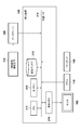
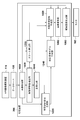
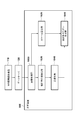
- FIG. 1 is a diagram showing a configuration of a processing system according to the present embodiment.
- the processing apparatus 100 includes an image acquisition unit 1000, an anatomical feature extraction unit 1020, a normalization unit 1040, an image deformation unit 1060, and an observation image generation unit 1080.
- the processing device 100 is connected to the data server 120 and the monitor 160.
- the MRI image capturing apparatus 110 is an apparatus that acquires an image obtained by nuclear magnetic resonance, that is, an MRI image, of information related to a three-dimensional region inside a subject that is a human body.
- the MRI image capturing apparatus 110 is connected to the data server 120 and transmits the acquired MRI image to the data server 120.
- the data server 120 is a device that holds the MRI image picked up by the MRI image pickup device 110, and transfers the MRI image held by a command from the processing device 100 to the processing device 100.
- the image acquisition unit 1000 captures the MRI image of the subject (target object) captured by the MRI image capturing apparatus 110 into the processing apparatus 100 via the data server 120.
- the anatomical feature extraction unit 1020 performs image processing on the MRI image captured by the image acquisition unit 1000 and extracts the anatomical features of the subject.
- the normalization unit 1040 calculates a conversion for converting (normalizing) the shape of the subject into a reference shape based on the anatomical feature of the subject extracted by the anatomical feature extraction unit 1020. Details regarding normalization will be described later.
- the image deformation unit 1060 performs alignment between the prone position and the supine position based on the conversion calculated by the normalization unit 1040, deforms the prone position MRI image, and generates a deformed image that matches the supine position MRI image.
- the observation image generation unit 1080 generates an observation image to be presented to the user from each of the MRI image captured by the image acquisition unit 1000 and the deformation image generated by the image deformation unit 1060. Then, the observation image is output to the monitor 160.
- the monitor 160 displays the observation image generated by the observation image generation unit 1080.
- FIG. 2 is a diagram showing an apparatus configuration of the processing system according to the present embodiment.
- the processing system of this embodiment includes a processing device 100, an MRI image capturing device 110, a data server 120, a monitor 160, a mouse 170, and a keyboard 180.
- the processing device 100 can be realized by, for example, a personal computer (PC).
- the processing device 100 includes a central processing unit (CPU) 211, a main memory 212, a magnetic disk 213, and a display memory 214.
- CPU central processing unit
- the CPU 211 mainly controls the operation of each component of the processing apparatus 100.
- the main memory 212 stores a control program executed by the CPU 211 and provides a work area when the CPU 211 executes the program.
- the magnetic disk 213 stores an operating system (OS), device drives of peripheral devices, various application software including programs for performing processing described later, and the like.
- the display memory 214 temporarily stores display data for the monitor 160.
- the monitor 160 is, for example, a CRT monitor or a liquid crystal monitor, and displays an image based on data from the display memory 214.
- the mouse 170 and the keyboard 180 are used for a pointing input by a user and an input of characters and commands, respectively.
- the above components are connected to each other via a common bus 218 so as to communicate with each other.
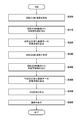
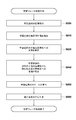
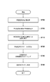
- FIG. 3 is a flowchart of processing executed by the processing apparatus 100 in the present embodiment.
- it is realized by the CPU 211 executing a program that realizes the function of each unit stored in the main memory 212.
- the results of each process performed by the processing apparatus 100 described below are recorded by being stored in the main memory 212.
- each processing step shown in FIG. 3 will be described in detail following the procedure.
- Step S300 Acquire Prone MRI Image
- the image acquisition unit 1000 obtains an MRI image (prone MRI image) in which the MRI image imaging device 110 images the subject's breast in the prone position.
- a process of importing into the processing apparatus 100 via 120 is executed.
- the prone position MRI image is three-dimensional volume data
- the direction from the foot side to the head side of the subject is the Z axis
- the direction from the ventral side to the dorsal side is the Y axis
- the left direction of the subject is X It is assumed that it has a three-dimensional orthogonal coordinate system as an axis (such coordinate conversion is performed in advance).
- this coordinate system is referred to as a prone position MRI image coordinate system.
- the luminance value of the prone position MRI image is expressed as a scalar function I p (x) with the three-dimensional position x in the prone position MRI image coordinate system as an argument.
- Step S310 Extract anatomical features from prone position MRI images
- the anatomical feature extraction unit 1020 processes the prone position MRI images acquired in step S300, thereby anatomical features in the prone position of the subject. Execute the process to extract.
- the anatomical features are the nipple position, body surface shape, pectoralis muscle surface shape, and reference position on the pectoralis muscle surface of the subject.
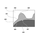
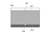
- FIG. 4 is a diagram for explaining anatomical features on the prone position MRI image.
- the actual prone position MRI image is a three-dimensional image.
- the prone position MRI image 400 includes an air region 403, a breast region 402, and an internal region 405.
- the body surface 401 is a set of positions at the boundary between the air region 403 and the breast region 402, and is a three-dimensional curved surface.
- the pectoralis major surface 404 is a set of boundaries between the breast region 402 and the internal region 405, and is a three-dimensional curved surface.
- the anatomical feature extraction unit 1020 detects the body surface 401 by performing image processing on the prone position MRI image 400 using a known method such as threshold processing or edge detection.
- the detection of the body surface 401 is not required to detect the entire body surface of the subject depicted in the prone position MRI image, and only the body surface related to the breast region and its surrounding region may be detected.
- the center position of the breast region in the prone position MRI image is acquired by user input using the mouse 170 or the keyboard 180, and the processing target is within a predetermined range from the center position.
- the body surface 401 is detected by the above method.
- the body surface shape which is a set of positions of the boundary between the air region 403 and the breast region 402, which is the body surface, is expressed as sp, surface, i (1 ⁇ i ⁇ Np , surface ) in this embodiment.
- N p, surface is the number of positions (points) constituting the body surface shape.
- the pectoralis major surface shape is also detected by image processing. In the present embodiment, this is expressed as sp, pectral, i ( 1 ⁇ i ⁇ Np, pectral ).
- N p, pectral is the number of positions (points) constituting the pectoralis major surface shape.
- the body surface shape and the pectoralis major surface shape are each accompanied by connection information between points constituting these.
- the body surface shape and the pectoralis major surface shape have information on a surface created by the point group in addition to information on a plurality of points (point group) representing the position.
- the anatomical feature extraction unit 1020 detects the nipple position.
- the nipple position can be detected by further processing the body surface shape detected by the above method. For example, the local curvature of the body surface shape can be calculated, and the position where the curvature is maximum can be detected as the nipple position.
- a position having the smallest Y-axis coordinate value (most ventral direction) in the MRI image coordinate system can be selected from all the positions constituting the body surface shape, and this can be set as the nipple position. It is also possible to detect the nipple position by performing image processing on the prone position MRI image.
- the detected nipple position is expressed as a three-dimensional coordinate value x p, surface .
- the anatomical feature extraction unit 1020 detects a reference position on the pectoralis major muscle surface. This process is executed, for example, by selecting a position closest to the nipple position among all positions constituting the pectoralis major surface shape.
- the detected three-dimensional coordinate value of the reference position on the pectoralis major muscle surface is expressed as x p, pectral .
- the anatomical feature extraction unit 1020 executes a process of performing coordinate transformation of the prone position MRI image coordinate system so that the nipple position x p, surface detected as described above is the origin. Specifically, it executes s p acquired in the process of the, surface, i, s p, pectral, i, x p, surface, x p, pectral the -x p, the process only to translate Surface. With the above processing, anatomical features are extracted in step S310.
- the processing apparatus 100 may display the prone position MRI image on the monitor 160 so that the user can input information on anatomical features to the processing apparatus 100 using the mouse 170 or the keyboard 180. Further, the anatomical features extracted by the image processing may be corrected / changed by the user using the mouse 170 or the keyboard 180. Further, the processing apparatus 100 may extract a part of the anatomical features by image processing and acquire the other by input by the user. At that time, a part of the anatomical features extracted by the image processing may be displayed on the monitor 160.
- the processing apparatus 100 extracts the body surface shape and the pectoralis major surface shape by image processing, and displays the results on the monitor 160. Then, the user may input the nipple position and the reference position on the pectoral muscle surface using the mouse 170 or the keyboard 180 to the processing device 100 while referring to the displayed body surface shape or pectoralis muscle surface shape. good.
- Step S320 Calculate transformation to the prone position normalized coordinate system
- the normalization unit 1040 calculates the shape of the subject in the prone position based on the anatomical features in the prone position extracted in step S310. Derive a normalization transformation to transform to the reference shape. Specifically, the normalization unit 1040 executes a process of calculating a coordinate conversion function between these coordinate systems as information representing conversion from the prone position MRI image coordinate system to the prone position normalized coordinate system. This conversion is such that each of the body surface and the pectoral muscle surface in the MRI image coordinate system is located on a predetermined plane in the prone position normalized coordinate system.
- this conversion is a conversion in which an arbitrary structure in the breast region is not damaged as much as possible before and after the conversion from the viewpoint of topology.
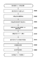
- a specific processing procedure executed by step S320 to calculate the coordinate transformation function will be described in detail with reference to the flowchart of FIG.
- Step S3200 Calculate the geodesic distance of the body surface
- the normalization unit 1040 based on the anatomical features extracted in step S310, at each position constituting the body surface shape of the subject in the prone position
- a process for calculating a geodesic distance based on the position is executed. That is, the normalization unit 1040 calculates the geodesic distance from the nipple at any other position, with the geodesic distance set to 0 for each nipple position among the positions constituting the body surface shape. Note that any known method may be used as a method of calculating the geodesic distance.
- the Dijkstra method can be used as a method for calculating the geodesic distance.
- the geodesic distance d p, surface, i (1 ⁇ i ⁇ N p, surface ) of each position constituting the body surface shape is calculated by the above processing.
- the subscript i is the same as the subscript i of the body surface shape sp , surface, i (1 ⁇ i ⁇ N p, surface ), and the position sp of the i- th body surface shape sp, surface, i
- d p, surface, i be the geodesic distance at.
- the normalization unit 1040 calculates the nipple position at each position constituting the body surface shape of the subject in the prone position based on the anatomical features extracted in step S310.
- a process for calculating a reference azimuth is executed.
- the orientation can be, for example, an orientation on the XZ plane in the MRI image coordinate system.
- the X coordinate value x i and the Z coordinate value z i are used to calculate the number.
- a p, surface, i [rad] can be calculated by the calculation shown in 1.
- the subscript i is the same as the subscript i of the body surface shape sp , surface, i (1 ⁇ i ⁇ N p, surface ), and the position sp of the i- th body surface shape sp, surface, i
- azimuth be a p, surface, i .
- direction is not restricted to said method, For example, it can calculate with the following method. That is, a vector connecting the nipple position and the reference position on the pectoral muscle surface is taken as the Y axis, and the body axis direction (direction from the foot side to the head side) of the subject is taken as the Z axis. However, if the Z axis is not orthogonal to the Y axis, correction is required. Then, the above equation 1 may be calculated after setting the outer product direction of the Y axis and the Z axis as the X axis.
- the orientation is determined with the coordinate axes based on the orientation of the subject. There is an effect that can be calculated.
- Step S3220> Calculate the geodesic distance of the pectoral muscle surface>
- the normalization unit 1040 based on the anatomical features extracted in step S310, on the pectoral muscle surface at each position sp, pectral, i constituting the pectoral muscle surface shape of the subject in the prone position.
- a process of calculating a geodesic distance d p, pectral, i (1 ⁇ i ⁇ N p, pectral ) based on the reference position x p, pectral of is executed. This processing step is executed by applying the same processing as step S3200 for the body surface to the pectoralis major muscle surface.
- Step S3230 Calculate the orientation of the pectoralis major plane
- the normalization unit 1040 determines each position s constituting the pectoralis major plane shape of the subject in the prone position based on the anatomical features extracted in step S310.
- p, Pectral, in i performs processing for calculating a reference position x p on the pectoralis major surface, orientation a p relative to the pectral, pectral, i a (1 ⁇ i ⁇ N p, pectral).
- This processing step is executed by applying the same processing as step S3210 for the body surface to the pectoralis major surface.
- Step S3240 Transform the body surface into a normalized coordinate system
- the normalization unit 1040 determines the subject in the prone position based on the geodesic distance and orientation on the body surface calculated in steps S3200 and S3210.
- a process for obtaining a transformation for converting the body surface shape of the body into a predetermined plane in the prone position normalized coordinate system is executed.
- the normalization unit 1040 corresponds to the position s ′ p, surface in the prone position normalized coordinate system corresponding to each position s p, surface, i constituting the body surface shape in the prone position MRI image coordinate system. , i is calculated.
- FIG. 6A is a schematic diagram of the breast in the prone position MRI image 400.
- FIG. FIG. 6B is a schematic diagram of the breast in the prone position normalization space expressed in the prone position normalization coordinate system.
- FIG. 6A and FIG. 6B are illustrated as a two-dimensional image for convenience of explanation on paper, but in actual processing, there is a three-dimensional space.
- the body surface 401 is a curved line in the figure, but is a curved surface in actual processing.
- the normalized surface 411 is a straight line in the figure, but is a plane in the actual processing. In this processing step, as shown in FIG.
- the normalization unit 1040 executes a process of performing coordinate conversion of the body surface 401 whose contour shape is a curved surface into a normalized body surface 411 which is a rectangular upper surface.
- the position of the normalized nipple 413 is defined in advance as a predetermined position.
- the position of the normalized nipple 413 is defined as the origin of the prone position normalized coordinate system.
- the body surface 401 is a set of N p, surface points denoted as sp, surface, i in this embodiment.
- the geodesic distance d p, surface, i and the direction a p, surface, i are calculated by the processing of step S3200 and step S3210.
- the normalization unit 1040 calculates a corresponding position in the prone position normalized coordinate system based on these calculation results. Specifically, the normalization unit 1040 calculates the coordinate value by calculation of Equation 2 to Equation 4.
- the position of the normalized body surface in the prone position normalized coordinate system calculated by the above processing is expressed as s ′ p, surface, i (1 ⁇ i ⁇ N p, surface ).
- Step S3250 Transform the pectoralis muscle surface into a normalized coordinate system
- the normalization unit 1040 determines the prone position based on the geodesic distance and orientation on the pectoral muscle surface calculated in steps S3220 and S3230.
- a process for obtaining a transformation for coordinate-transforming the shape of the pectoralis major muscle surface of the subject to a predetermined plane in the prone position normalized coordinate system is executed.
- the normalization unit 1040 corresponds to the position s ′ p in the prone position normalized coordinate system corresponding to each position s p, pectral, i constituting the pectoralis major plane shape in the prone position MRI image coordinate system.
- pectral, i is calculated.
- the normalization unit 1040 executes processing on the pectoralis major muscle surface in the same manner as in step S3240 for the body surface. That is, the normalization unit 1040 executes processing for coordinate-transforming the pectoralis major muscle surface 404 whose contour shape is a curved surface as shown in FIG. 6A into a normalized pectoral major muscle surface 412 which is a lower plane of the rectangular shape. .
- the position of the reference point 414 of the normalized pectoral muscle surface is defined in advance as a predetermined position.
- the reference point 414 of the normalized pectoral muscle surface is defined as coordinate values (0, 100, 0) of the prone position normalized coordinate system.
- a specific process is executed by the normalization unit 1040 performing calculations of Formulas 5 to 7 for all points sp, pectral, i on the pectoralis muscle surface 404. That is, the normalizing unit 1040 performs coordinate conversion on all points on the same xz plane as the reference point 414 on the normalized pectoralis major muscle surface. At this time, the normalization unit 1040, for all points, the distance and orientation with respect to the reference point 414 of the normalized pectoralis muscle surface are geodesic from the reference point of the pectoral muscle surface in the prone MRI image coordinate system Match the line distance d p, pectral, i and the orientation a p, pectral, i .
- Step S3260 Calculate Normalization Deformation
- the normalization unit 1040 uses a coordinate conversion function (deformation) between the coordinate systems as information representing conversion from the prone position MRI image coordinate system to the prone position normalized coordinate system.
- the process of calculating the field is executed. That is, the normalization unit 1040 spatially interpolates the result group of the discrete coordinate conversion to the prone position normalized coordinate system of the body surface and pectoral muscle surface obtained in steps S3240 and S3250, and Calculate the dense transformation from the MRI image coordinate system to the prone position normalized coordinate system.
- this processing can be realized by a known interpolation method using a radial basis function, a B-spline, or the like.
- ⁇ p (x) The transformation function from the prone position MRI image coordinate system calculated in this processing step to the prone position normalized coordinate system is expressed as ⁇ p (x) in this embodiment.
- ⁇ p (x) is a function that takes the position coordinate value in the prone position MRI image coordinate system as an argument and returns the corresponding position coordinate value in the prone position normalized coordinate system.
- the normalization unit 1040 calculates a function that returns the position of the prone position MRI image coordinate system corresponding to the position coordinate value in the prone position normalization coordinate system as an argument, similarly to ⁇ p (x). .
- this is expressed as ⁇ p ⁇ 1 (x).
- ⁇ p ⁇ 1 (x) is defined in a predetermined rectangular region in the prone position normalized coordinate system.
- the rectangular area is, for example, a rectangular area that includes all of s ′ p, surface, i and s ′ p, pectral, i .
- Equation 8 s' p, surface, i ⁇ ⁇ p (s p, surface, i ) (Equation 9) s' p, pectral, i ⁇ ⁇ p (s p, pectral, i ) (Equation 10) s p, surface, i ⁇ ⁇ p -1 (s' p, surface, i ) (Equation 11) s p, pectral, i ⁇ ⁇ p -1 (s' p, pectral, i )
- Step S340 Acquisition of Supine Position MRI Image
- the image acquisition unit 1000 captures an MRI image (a supine position MRI image) obtained by imaging the subject's breast in the supine position from the data server 120 to the processing apparatus 100. Execute the process. Since this process can be executed in the same procedure as Step S300 for the prone position MRI image, detailed description thereof is omitted.
- the acquired supine position MRI image is three-dimensional volume data in the supine position MRI image coordinate system.
- Step S350 Extract anatomical features from the supine position MRI image
- the anatomical feature extraction unit 1020 processes the supine position MRI image acquired in step S340, thereby anatomical features in the supine position of the subject. Execute the process to extract. Since this process can be executed by applying the same process as step S310 for the prone position MRI image to the supine position MRI image, detailed description thereof will be omitted.
- the body surface shape in the supine position extracted in this processing step is s s, surface, i (1 ⁇ i ⁇ N s, surface ), and the pectoral muscle surface shape is s s, pectral, i (1 ⁇ i ⁇ N s, pectral ), the nipple position is expressed as x s, surface , and the pectoral muscle surface reference point is expressed as x s, pectral .
- Step S360 Calculation of conversion to the supine position normalized coordinate system
- the normalization unit 1040 calculates the shape of the subject in the supine position based on the anatomical features in the supine position extracted in step S350. Derive a normalization transformation to transform to the reference shape.
- the normalizing unit 1040 executes a process of calculating a coordinate conversion function between these coordinate systems as information representing conversion from the supine position MRI image coordinate system to the supine position normalized coordinate system. Since this process can be executed by applying the same procedure as step S320 for the prone anatomical feature to the supine anatomical feature, detailed description thereof will be omitted.
- the conversion function from the supine position MRI image coordinate system acquired in this processing step to the supine position normalized coordinate system is denoted as ⁇ s (x).
- a conversion function from the supine position normalized coordinate system to the supine position MRI image coordinate system is denoted as ⁇ s ⁇ 1 (x).
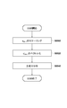
- Step S380 Deformation of MRI Image
- the image deformation unit 1060 executes a process of generating a deformed image obtained by deforming the prone position MRI image into the supine position based on the processing results of steps S320 and S360. Specifically, the image deformation unit 1060, prone position for all voxels that constitutes the MRI image (pixels constituting the volume data), and the coordinate transformation by calculating the position x p number 12 of that voxel, conversion The subsequent position xd is calculated.
- x d ⁇ s -1 [ ⁇ ps ⁇ p (x p ) ⁇ ]
- the image transformation unit 1060 generates volume data having a luminance value I p (x p ) at the converted position x d .
- the function ⁇ ps (x) is an arbitrary conversion function between the prone position normalized coordinate system and the supine position normalized coordinate system, and is assumed to be an identity function shown in Equation 13 herein.
- the domain of the transformation function ⁇ ps (x) is the same rectangular area as ⁇ p ⁇ 1 (x).
- x ⁇ ps (x)
- the volume data generated by the above processing is expressed as a modified MRI image I d (x).
- I d (x) I p [ ⁇ p -1 ⁇ ps -1 ( ⁇ s (x)) ⁇ ]
- the calculation of the number 12 executed in this processing step means the following. That is, the position x p in the prone position MRI image coordinate system is converted into the prone position normalized coordinate system, and the coordinate value is supine after equating the prone position normalized coordinate system and the supine position normalized coordinate system.
- the position has been converted to the MRI image coordinate system.
- it is assumed that the difference in shape between the prone position and the supine position is canceled by the respective normalizations (anatomically identical points are mapped to the approximate coordinates of the normalized coordinate system by normalization). Based on that assumption, it means that conversion between the prone position MRI image coordinate system and the supine position MRI image coordinate system is required (deformation alignment is performed).
- ⁇ ps (x) may be a deformation function that increases the similarity between images between the deformed MRI image and the supine position MRI image.
- ⁇ ps (x) it can be expressed using FFD (Free Form Deformation), which is one of the typical methods of nonlinear coordinate transformation. In this case, processing for optimizing the FFD deformation parameters is performed so as to maximize the similarity between images shown in Formula 15.
- I s (x) is a supine position MRI image
- ⁇ is a breast region in the supine position MRI image coordinate system.
- Optimization of FFD deformation parameters is performed by well-known nonlinear optimization methods such as steepest gradient method.
- the similarity between images may be any known method for calculating the similarity between images, such as a method using cross-correlation or mutual information, in addition to the calculation method shown in Equation 15.
- deformation with high similarity in the luminance values of the prone position MRI image and the supine position MRI image is performed. Can be generated. For this reason, there is an effect that the alignment between the prone position MRI image and the supine position MRI image can be executed with higher accuracy.
- Step S390 In the display step S390 the deformed image, the observation image generating unit 1080 generates modified image I d (x) generated in step S380, an observation image obtained by arranging the supine position MRI image I s (x) To do. At this time, the observation image generation unit 1080 cuts out an image (cross-sectional image) obtained by cutting each of the deformed image I d (x) and the supine position MRI image I s (x) at an arbitrary plane in accordance with a user operation, These can be arranged side by side to form an observation image.
- the observation image generation unit 1080 may configure an observation image by arranging images obtained by volume rendering of the deformed image I d (x) and the supine position MRI image I s (x). Further, the observation image generation unit 1080 may configure an observation image by superimposing or fusing cross-sectional images generated from the deformed image I d (x) and the supine position MRI image I s (x). Then, the observation image generation unit 1080 executes processing for displaying the observation image generated by the above processing on the monitor 160.
- the processing of the processing apparatus 100 according to the first embodiment is performed by the method described above.
- normalization is performed in consideration of biomechanical characteristics related to the deformation of the breast, so that the change in position due to the deformation can be generally absorbed and converted into an anatomically common space. Therefore, normalization conversion can be performed in which each of the breasts of the subject imaged in the prone position and the supine position is mapped to a space that approximately matches anatomically.
- the normalization unit 1040 has been described as an example in which the breast region 402 illustrated in FIG. 6A generates a normalization deformation having a rectangular shape illustrated in FIG.
- the shape is not limited to this case.
- the breast region in the normalized coordinate system may have a shape other than the rectangular shape.
- it may be a shape surrounded by an arbitrary geometric curved surface such as a quadric surface.
- the processing apparatus 100 may be provided with a plurality of pieces of shape information in advance, and the user may arbitrarily select among them.
- the processing apparatus 100 presents the prone position MRI image and the supine position MRI image to the user by displaying them on the monitor 160, for example, so that the user can select appropriate shape information while observing the image.
- the normalization deformation method can be adaptively selected for the characteristics of the breast that can have various shapes for each subject, and there is an effect that alignment with higher accuracy can be performed.
- the image deforming unit 1060 generates a deformed MRI image obtained by deforming the prone position MRI image in the process of step S380 has been described.
- the MRI image to be performed is not limited to this example.
- the image deforming unit 1060 converts the prone position MRI image into the prone position normalized coordinate system and the supine position MRI image into the supine position normalized coordinate system. A case where a supine position normalized image is generated and these images are displayed side by side will be described.
- step S380 and step S390 in the present embodiment will be described.
- step S380 the image deforming unit 1060 generates a prone position normalized image I pd obtained by converting the prone position MRI image I p to the prone position normalized coordinate system based on the conversion function ⁇ p ⁇ 1 (x).
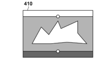
- 7A to 7D are diagrams showing specific examples of images generated by this processing.
- the prone position MRI image 400 is an example schematically representing I p .
- the image deforming unit 1060 deforms the prone position MRI image 400 based on the transformation function ⁇ p ⁇ 1 (x), thereby normalizing the prone position as an image in the prone position normalized coordinate system, as shown in FIG.
- An image 410, i.e., I pd is generated.
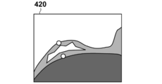
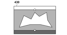
- Image transforming unit 1060 in addition step S380 performs the same processing for the supine position MRI image I s, is modified based supine MRI image 420 of FIG. 7C to ⁇ s -1 (x), supine Figure 7D A position normalized image 430, ie, I sd is generated.
- the prone position normalized image I pd and the supine position normalized image I sd which are three-dimensional volume data are generated.
- the value of the Y coordinate generally represents the ratio of the distance between the body surface and the pectoral muscle surface.
- the slice images I slice, pd and I slice, sd have a curved surface shape with a constant ratio of the distance between the body surface and the pectoral muscle surface in the prone MRI image coordinate system and the supine MRI image coordinate system.
- the cross section (curved cross section) is cut out. For this reason, there is an effect that the two images can be easily compared with each other from a medical and anatomical viewpoint. For example, there is an effect that a single cross-sectional image can compare and observe the running of superficial blood vessels existing near the body surface of the breast and the spread of the mammary gland in the breast region over a wide range.
- the process of generating and displaying the curved section of the MRI image as described above does not necessarily have to be performed on both the prone position MRI image and the supine position MRI image.
- the processing apparatus 100 receives either the prone position MRI image or the supine position MRI image as input, and executes the process from step S300 to step S320 of the first embodiment to generate the curved section described above. May be displayed. According to this method, there is an effect that it is possible to perform advanced image observation from a medical / anatomical viewpoint such as running of superficial blood vessels and spreading of mammary glands.
- the processing apparatus 200 applies normalization processing similar to that of the first embodiment to multiple cases (learning cases), and each normalized A model related to deformation (statistic deformation model) is constructed by statistically processing the deformation of the case.
- normalization between different cases will be described.
- At least the normal human body has almost the same anatomical structure from a topological point of view, regardless of individual differences. Individual differences can be absorbed by scale conversion (similarity conversion).
- scale conversion similarity conversion
- the nipple, body surface, pectoral muscle surface, midline, head-tail direction (body axis), etc. are characteristic geometric structures that are anatomically common to all individuals.
- the processing apparatus 200 considers the space normalized by the characteristic geometric structure in addition to the scale conversion between individuals, and the breasts of human bodies of different individuals are included in the space. Convert coordinates. Thereby, the difference between individuals can be generally absorbed and converted into an anatomically common space.
- the processing apparatus 200 estimates the deformation by fitting a statistical deformation model to an unknown case (target case) different from the learning case. Thereby, the deformation position alignment between the MRI images of the prone position and the supine position of the target case is performed with high accuracy.
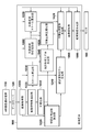
- FIG. 8 is a diagram showing a configuration of a processing system according to the present embodiment.
- the processing device 200 in this embodiment includes an image acquisition unit 1000, an anatomical feature extraction unit 1020, a normalization unit 1040, a learning case deformation generation unit 1220, a scale calculation unit 1230, and a statistical deformation model generation unit. 1240, a subject case deformation generation unit 1420, an image deformation unit 1060, and an observation image generation unit 1080.
- generation part 1220 produces
- the scale calculation unit 1230 calculates a scale for each of the learning cases.
- the statistical deformation model generation unit 1240 generates a statistical deformation model based on the deformation / scale regarding each of the learning cases.
- the target case deformation generation unit 1420 generates a deformation between the prone position and the supine position of the target case.
- the processing of the processing device 200 includes a learning phase process and a deformation estimation phase process.
- the learning phase process is performed, and then the deformation estimation phase process is performed.
- the process of the learning phase the process of learning the deformation between the MRI images of the prone position and the supine position of many cases and generating a statistical deformation model is executed.
- the deformation estimation phase the deformation positioning between the prone position and the supine position of the target case is executed using the statistical deformation model calculated in the learning phase.
- the processing device 200 executes both the learning phase process and the deformation estimation phase process will be described as an example.
- the learning phase process and the deformation estimation phase process are described. May be executed by a different processing apparatus.
- the processing device 200 according to the present embodiment is not limited to executing both the learning phase process and the deformation estimation phase process, and may execute only the learning phase process, for example.
- the provision of the statistical deformation model itself obtained as a result of the learning phase process is also included in the present embodiment.
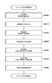
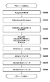
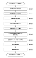
- FIG. 9 is a flowchart for explaining the procedure of the learning phase process performed by the processing apparatus 200 according to this embodiment.
- learning phase processing the learning phase processing of the present embodiment will be described in detail.
- Step S500 Calculation of Learning Case Image
- the image acquisition unit 1000 executes a process of acquiring prone MRI images and supine MRI images of N samples of learning cases. This process can be executed by applying the same process as steps S300 and S340 of the first embodiment to each of the N samples learning cases. Detailed description is omitted.
- Step S510 Extracting Anatomical Features of Learning Case
- the anatomical feature extracting unit 1020 performs anatomy by processing each of the prone position MRI image and the supine position MRI image of the learning case acquired in step S500.
- a process for extracting academic features is executed. This process can be executed by applying the same process as steps S310 and S350 of the first embodiment to each of the N samples learning cases. Detailed description is omitted.
- Step S520 Calculate a deformation function to the normalized coordinate system of the learning case
- the normalization unit 1040 for each of the learning cases based on the anatomical features of the learning case extracted in step S510
- a normalization transformation is derived that transforms the shape into a reference shape.
- the normalization unit 1040 executes a process of calculating a deformation function from the prone position MRI image coordinate system to the prone position normalized coordinate system for each prone position MRI image.
- the normalization unit 1040 executes a process of calculating a deformation function from the supine position MRI image coordinate system to the supine position normalized coordinate system for each of the supine position MRI images.
- the deformation function of the prone position normalized coordinate system is expressed as ⁇ p, j (x) from the prone position MRI image coordinate system of the learning case calculated by the above processing.
- the transformation function from the supine position MRI image coordinate system to the prone position normalized coordinate system is expressed as ⁇ s, j (x).
- j means the case number of the learning case, and 1 ⁇ j ⁇ N samples . That is, a process for obtaining a deformation function is executed for each of the N samples learning cases.
- Step S540 Calculate a conversion function from the prone position normalized coordinate system of the learning case to the supine position normalized coordinate system.
- the learning case deformation generation unit 1220 determines the prone position normalized coordinate system for each of the learning cases.
- a process of calculating a conversion function from to the supine position normalized coordinate system is executed. Specifically, the learning case deformation
- generation part 1220 acquires the position which respond
- FIG. it is assumed that the corresponding position is input from the user.
- the corresponding positions in the input prone position MRI image coordinate system and supine position MRI image coordinate system are x p, corres, k and x s, corres, k , respectively.
- k is the index of the corresponding points is 1 ⁇ k ⁇ N corres when the number of positions corresponding to N corres.
- the corresponding position is, for example, a branch point of a blood vessel in an MRI image, a part having a characteristic structure of a mammary gland, or the like, and is a set of positions to which a user can give a correspondence visually.
- generation part 1220 converts each of acquired xp, corres, k, xs, corres, k using the conversion to the normalization coordinate system acquired by step S520. Specifically, the learning case deformation
- the learning case deformation generation unit 1220 converts the prone position normalized coordinate system to the supine position normalized coordinate system based on the calculated x ′ p, corres, k and x ′ s, corres, k .
- the conversion function ⁇ ps, j (x) is calculated.
- generation part 1220 calculates conversion function (phi) ps, j (x) so that the relationship of several 18 may be approximated with the minimum error.
- the transformation function ⁇ ps, j (x) is a continuous function defined in the prone position normalized coordinate system, specifically expressed using FFD (Free Form Deformation), RBF (Radial Basis Function), etc. You can do that.
- generation part 1220 in the positional relationship between a prone position and a supine position, the conditions that body surfaces and pectoral muscle surfaces agree, and the inside of the breast which the user input etc. It is possible to obtain a conversion function that considers both the corresponding position information.
- generation part 1220 performs the process demonstrated above about each of N samples learning cases, and is converted from a prone position normalization coordinate system to a supine position normalization coordinate system about each case.
- the conversion function ⁇ ps, j (x) is calculated.
- generation part 1220 acquires the information of the position corresponding to both a prone position MRI image coordinate system and a supine position MRI image coordinate system, and based on it, deformation
- generation part 1220 is the deformation
- the learning case deformation generation unit 1220 determines the similarity between images of the prone position MRI image and the supine position MRI image. Based on this, the deformation function ⁇ ps, j (x) may be calculated. According to said method, there exists an effect which can acquire the deformation
- Step S550 Calculation of Learning Case Scale
- the scale calculation unit 1230 executes a process of calculating a case scale for each of the learning cases.
- the scale of the case is a numerical value representing the size of the breast region that is different for each case.
- the scale is calculated by, for example, measuring the distance between the nipple position of the subject in the prone position and the body surface position immediately above the midline closest to the nipple position.
- the user may input a numerical value measured directly using a measuring instrument to the subject in the prone position into the processing apparatus 200.
- the processing apparatus 200 may be configured to measure the above distance value on the prone position MRI image.
- the processing apparatus 200 may calculate the measurement value by automatically processing the prone position MRI image.
- the processing device 200 may present the prone position MRI image to the user using the monitor 160 or the like, and obtain the measurement value by operating the mouse 170 or the keyboard 180 by the user.
- the processing apparatus 200 displays a prone position MRI image on the monitor 160, and displays the nipple position of the subject depicted on the image and the body surface position directly on the midline closest to the nipple position. This can be achieved by calculating the distance between them.
- the method for calculating the scale of the case using the distance (Euclidean distance) between the nipple position and the body surface position on the midline closest to the nipple position has been described. It is not limited to this method.
- the scale may be calculated using the geodesic distance between the two points. According to this, there is an effect that it is possible to calculate a scale value in consideration of the difference in the shape of the breast for each case.
- the calculation of the scale is not limited to the distance between the two points or the geodesic distance, and may be calculated based on the volume of the breast region, the distance to the outer edge of the breast, the chest circumference of the subject, and the like. . Further, the method for calculating the scale is not limited to one.
- the scale may be calculated based on values calculated by a plurality of types of methods.
- a multi-dimensional scale value obtained by vectorizing values calculated from a plurality of types may be used, or a scale value may be calculated as a scalar value by an average operation or a linear combination operation of values calculated by a plurality of types. May be.
- the scale calculated by the method described above is expressed as v j (1 ⁇ j ⁇ N samples ).
- the scale value is the ratio between the scalar value, which is the distance (Euclidean distance) between the nipple position in the prone position and the body surface position on the median line closest to the nipple position, and a predetermined reference value.
- the predetermined reference value is, for example, a value of a distance between a nipple position in a standard breast and a body surface position on the midline closest to the nipple position.
- Step S580 Generation of Statistical Deformation Model
- the statistical deformation model generation unit 1240 is based on ⁇ ps, j (x), v j related to N samples objects calculated by the processing from step S500 to step S570.
- FIG. 10 is a flowchart for explaining the process of step S580 in more detail. Hereinafter, description will be given along the flowchart of FIG.
- Step S5800 Scaling of ⁇ ps, j (x)
- the statistical deformation model generation unit 1240 is based on the transformation function ⁇ ps, j (x) and the scale v j for N samples cases.
- the conversion function ⁇ ′ ps, j (x) is calculated as shown in Equation 19.
- the domain of ⁇ ′ ps, j (x) is an area that is reduced by the scale value v j of the case with respect to the X coordinate and the Z coordinate as compared with the domain of ⁇ ps, j (x).
- Statistical deformation model generation unit 1240 the above process the N samples number of conversion functions phi ps of all cases, j (x) (1 ⁇ j ⁇ N samples) was performed for the conversion function phi 'scaled processing each case ps, j (x) (1 ⁇ j ⁇ N samples ) is calculated.
- Step S5820 Vectorization of ⁇ ′ ps, j (x)
- the statistical deformation model generation unit 1240 discretizes the transformation function ⁇ ′ ps, j (x) after the scaling processing calculated in step S5800. Execute the process. This discretization process is executed according to the following procedure.
- the statistical deformation model generation unit 1240 obtains a common domain of the conversion function ⁇ ′ ps, j (x) for N samples cases.
- Each of the N samples conversion functions ⁇ ′ ps, j (x) has a different domain depending on the shape of the body surface and the pectoral muscle surface of each case, the scale value, etc.
- N samples The region where ⁇ ′ ps, j (x) is defined in all cases is defined as a common domain. Therefore, in this domain, all N samples conversion functions ⁇ ′ ps, j (x) have values.
- the statistical deformation model generation unit 1240 samples the value of the conversion function ⁇ ′ ps, j (x) over the common domain, and generates a discretized vector in which the sampling results are arranged vertically.
- the generation of the discretized vector is a vector in which values sampled in a raster scan form at predetermined intervals in the above defined area are arranged in order. Since the transformation function ⁇ ′ ps, j (x) is a function that returns a three-dimensional value of x, y, and z, the statistical deformation model generation unit 1240 generates a discretized vector for each coordinate axis.
- the discretized vectors for the three-dimensional coordinate axes of x, y, and z are p x, j , p y, j , and p z, j .
- the discretized vector is a real vector having dimensions corresponding to the number of times of sampling by the raster scan.
- the statistical deformation model generation unit 1240 applies the processing described above to all N samples conversion functions ⁇ ′ ps, j (x). As a result, N samples discretized vectors p x, j , p y, j and p z, j are obtained. Note that the discretized vector obtained by the raster scan sampling can be inversely converted into a real space conversion function by an arbitrary interpolation function or the like. In the present embodiment, an interpolating function f interp (p x, j , p y, j , p z) using the discretized vectors p x, j , p y, j , p z, j and the real space position x as arguments. , j , x) approximate ⁇ ′ ps, j (x).
- Step S5840 Statistical Deformation Model Generation by Principal Component Analysis
- the statistical deformation model generation unit 1240 the discretization vector p x, j , p y, j , p z, j (1 ⁇ j calculated in step S5820)
- a process of generating a statistical deformation model is executed by performing principal component analysis of ⁇ N samples ). Since the principal component analysis can be executed by a known method, a detailed description is omitted here.
- the statistical deformation model generation unit 1240 calculates the mean vector e ave, x , e ave, y , e ave, z and the eigenvectors e x, k , e y, k , e z for each discretization vector. , k (1 ⁇ k ⁇ N mode ).
- N mode is the total number of eigenvectors calculated by principal component analysis, and can be set, for example, by setting a predetermined threshold for the cumulative contribution rate calculated by principal component analysis.
- the average vector and eigenvector calculated by the above processing are called a statistical deformation model.
- Equation 20 E x is a matrix in which e x, k are arranged horizontally.
- b is a vector in which b k is vertically arranged, and in the present embodiment, this is called a coefficient vector.
- the learning phase processing of the present embodiment is executed by the processing from step S500 to step S580 described above. As a result of this processing, a statistical deformation model is generated.
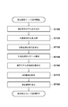
- FIG. 11 is a flowchart for explaining the processing procedure of the deformation estimation phase performed by the processing device 200 according to this embodiment.
- the process of the deformation estimation phase of the present embodiment will be described in detail according to the processing procedure shown in this flowchart.
- Step S600 Statistical Deformation Model Reading
- the processing device 200 executes a process of reading the statistical deformation model generated by the learning phase processing into the main memory 212 of the processing device 200.
- Step S602 Image acquisition of target case
- the image acquisition unit 1000 executes a process of acquiring MRI images of the prone position and the supine position of the target case. This processing can be executed by the same processing as Step S300 and Step S340 of the first embodiment. Detailed description is omitted.
- Step S604 Extracting Anatomical Features of Target Case
- the anatomical feature extracting unit 1020 processes the prone and supine MRI images of the target case acquired in step S602, and anatomy of the target case A process for extracting features is executed. This process can be executed by the same process as the process of step S310 and step S350 of the first embodiment. Detailed description is omitted.
- Step S610 Calculate transformation of the target case into a normalized coordinate system
- the normalization unit 1040 based on the anatomical features of the target case extracted in step S604, from the prone position MRI image coordinate system of the target case
- a process of calculating conversion to the prone position normalized coordinate system and conversion from the supine position MRI image coordinate system to the supine position normalized coordinate system is executed. This process is executed by applying the same process as the process of step S520 described as the process of the learning phase to the target case. Detailed description is omitted.
- the transformation from the prone position MRI image coordinate system calculated by this processing to the prone position normalized coordinate system is defined as ⁇ p, target (x). Also, let ⁇ s, target (x) be the transformation from the supine position MRI image coordinate system to the supine position normalized coordinate system.
- Step S630 Scale calculation of target case
- the scale calculation unit 1230 executes a process of calculating the scale of the target case. This process is executed by applying the same process as the process of step S550 described as the process of the learning phase to the target case. Detailed description is omitted.
- the scale of the target case calculated by this processing is set as v target .
- Step S640 Optimization of coefficients of statistical deformation model
- the target case deformation generation unit 1420 performs a process of calculating conversion between the prone position MRI image coordinate system and the supine position MRI image coordinate system of the target case. Execute. That is, the target case deformation generation unit 1420 executes deformation alignment processing between the prone position MRI image and the supine position MRI image. This process is executed based on the statistical deformation model acquired in the process of the learning phase and the MRI images of the prone position and the supine position of the target case. Specifically, a coefficient vector b that maximizes the evaluation function G (b) calculated by the calculation shown in Equation 21 is calculated.
- G (b) G simil ⁇ D (I p , b), I s ⁇
- the I p prone position MRI image, I s of the object cases are supine position MRI image of the object cases.
- the function G simil (I 1 , I 2 ) is a function for evaluating the degree of similarity between two images given as arguments. For example, a known image between SSD, SAD, cross-correlation, mutual information, etc. This can be realized by the similarity evaluation method.
- the function D (I, b) is a function that deforms the image I based on the coefficient vector b of the statistical deformation model. More specifically, the function D (I, b) performs the following processing. That is, based on the coefficient vector b, the discretized vectors p x , p y , and p z are calculated by the calculation shown in Equation 22. (Equation 22)
- ⁇ target (x) ⁇ s -1 [f interp ⁇ p x , p y , p z , ⁇ p (x) ⁇ ]
- a conversion function ⁇ ′ target (x) obtained by scaling the conversion function ⁇ target (x) using the scale v target of the target case calculated in step S630 is calculated by Expression 24 (Expression 24)
- ⁇ ' target (x') ⁇ target (x) x v target
- x ′ (x ⁇ v target , y, z ⁇ v target ) T
- x (x, y, z) T.
- ⁇ ′ target (x) is a function obtained by scaling ⁇ target (x) by the scale value v j of the target case with respect to the X coordinate and the Z coordinate and further scaling the function value by the scale value v target .
- Equation 21 The function D (I, b) deforms the image I based on the deformation function ⁇ ′ target (x). That is, D (I p , b) in Equation 21 is calculated as shown in Equation 25 below.
- the evaluation function G (b) shown in Equation 21 evaluates the similarity between the image obtained by deforming the prone position MRI image and the supine position MRI image based on the coefficient vector b.
- the target case deformation generation unit 1420 uses a nonlinear optimization method such as the steepest descent method, the quasi-Newton method, or the conjugate gradient method to maximize the coefficient vector b
- the process of calculating is executed.
- the coefficient vector obtained by this processing is expressed as b opt .
- the case where the coefficient vector is calculated based on the inter-image similarity between the deformed MRI image obtained by deforming the prone position MRI image and the supine position MRI image is described as an example. Is not limited to this example.
- the processing device 200 acquires these position information, and the target case deformation generation unit 1420
- a coefficient vector may be calculated so as to approximate the relationship. For example, when the processing device 200 acquires the corresponding position by the user's input, there is an effect that the deformation can be estimated so that the position that the user wants to match between both images is matched. .
- a new evaluation function is added to the evaluation function for the similarity between images shown in Equation 21 and an evaluation function for the error of the corresponding position between the prone position MRI image and the supine position MRI image of the target case. Also good. According to this, there is an effect that more accurate deformation estimation can be performed based on both information of the similarity between images and the corresponding position input by the user.
- the above-described corresponding position information is not necessarily acquired by user input, and a feature point detection / feature point association method using nSIFT or the like from both prone MRI images and supine MRI images For example, the corresponding position information may be automatically acquired. According to this, there is an effect that the deformation estimation can be executed more efficiently.
- the coefficient vector calculated in this processing step does not necessarily have to be obtained by maximizing the evaluation function.
- the coefficient vector may be a zero vector.
- the deformation calculated in this processing step is the average deformation calculated in S580, which is the processing of the learning phase in the present embodiment, but ⁇ ps (x) is identical in the first embodiment described above. According to the comparison with the case of using a function, more accurate deformation estimation can be performed. ]
- Step S650 Deformation of MRI Image
- the image deformation unit 1060 executes a process of generating a deformed MRI image obtained by deforming the prone position MRI image based on the conversion calculated in step S640. Specifically, the image deformation unit 1060 uses the image deformation function D (I, b) shown in Equation 24 and deforms the prone position MRI image I p of the target case based on the coefficient vector b opt. MRI image Id is calculated.
- Step S660 displaying a deformed image step S600
- the observation image generating unit 1080 generates an observation image obtained by arranging the supine position MRI image I s modified MRI image I d and the object cases generated in step S650. Since the specific process of this process step is the same as the process of step S390 in the first embodiment, detailed description thereof is omitted.
- the deformation estimation phase processing of this embodiment is executed by the processing from step S600 to step S660 described above.
- a deformation estimation process between the prone position MRI image and the supine position MRI image related to the target case is executed.
- a deformed MRI image obtained by deforming the prone position MRI image so as to correspond to the supine position MRI is generated and displayed together with the supine position MRI image, so that the input image is presented in a form that is easy to compare.
- the transformations ⁇ p and ⁇ s into the normalized coordinate system in step S540 and step S610 can be transformation functions to standard shapes related to the prone position and the supine position.
- the standard shape can be, for example, a breast shape of a specific case.
- the user can arbitrarily select one of N samples cases to be learned in the present embodiment, and the body surface shape and the pectoralis major shape of the selected case can be set as the standard shape.
- the standard shape may be the average shape of N samples cases to be learned.
- the standard shape is not necessarily selected from the learning cases, and the body surface shape and the pectoralis major shape of a case different from the learning case may be used.
- it is not limited to the case of using a specific shape of a specific case, and may be, for example, an artificially constructed simulated breast shape.
- a shape obtained by cutting a sphere or an ellipsoid, a shape such as a cone, or a bowl may be used as the standard shape.
- the same shape may be used as the standard shape in the prone position and the supine position, and different shapes may be used as the standard shapes.
- the processing apparatus 200 may have information regarding a plurality of standard shapes in advance, and an appropriate standard shape may be selected based on the anatomical characteristics of the learning case.
- the statistical deformation model in the present embodiment is a model that approximates and expresses a conversion function between a coordinate system based on the standard shape in the prone position and a coordinate system based on the standard shape in the supine position. It is.
- the deformation between the normalized coordinate systems of the learning cases may be FFD.
- SDM may be used as the statistical model.
- the case where the deformation ⁇ ps, j (x) calculated in step S540 is developed as a deformation field (discretization vector) in the space of the normalized coordinate system has been described as an example of the processing in step S580. However, this development may be performed in another form.
- step S540 the deformation ⁇ ps, j (x) is expressed by FFD, and the FFD parameters (control amounts possessed by the control points) are vectorized to obtain discretized vectors p x, j , p y, j , p z, j may be calculated.
- the statistical deformation model can be constructed by a method (Statistical Deformation Model method) disclosed in Non-Patent Document 2. According to this method, there is no need to execute the process of expanding the deformation ⁇ ps, j (x) as a discretized vector of the deformation field in step S580, and there is an effect that the amount of calculation processing and the memory capacity can be reduced. .
- FIG. 800 Example of constructing a statistical atlas of prone breasts
- the processing apparatus 800 uses an MRI image obtained by imaging multiple cases of breasts in the prone position as learning data, and breasts that differ between cases After normalizing the shape, a statistical shape model that efficiently expresses the shape is constructed.
- a case where a breast imaged in the prone position is used as learning data will be described as an example, but a breast in another position may be used. For example, it may be a supine position or a standing position.
- FIG. 12 is a diagram showing a configuration of a processing system according to the present embodiment.
- the processing device 800 in this embodiment includes an image acquisition unit 1000, an anatomical feature extraction unit 1020, a normalization unit 1040, a scale calculation unit 1620, and a statistical shape model generation unit 1640.
- the scale calculation unit 1620 calculates a scale for each of the learning cases.
- the statistical shape model generation unit 1640 generates a statistical shape model based on the deformation / scale regarding each of the learning cases.
- FIG. 13 is a flowchart for explaining the processing procedure of the processing apparatus 800 in the present embodiment. Hereinafter, it demonstrates along this figure.
- Step S700 Acquisition of Learning Case Image
- the image acquisition unit 1000 executes a process of acquiring a prone position MRI image of a learning case.
- the image acquisition unit 1000 acquires prone MRI images of N samples learning cases. This process is executed by applying the same process as step S300 in the first embodiment to each of the N samples learning cases. Detailed description is omitted.
- Step S705 Extract anatomical features of learning case
- the anatomical feature extraction unit 1020 processes each prone position MRI image of the learning case acquired in step S700 to extract the anatomical features of the learning case. Execute the process. This process is executed by applying the same process as step S310 in the first embodiment to each of the N samples learning cases. Detailed description is omitted.
- Step S710 Calculation of Conversion of Learning Case to Normalized Coordinate System
- the normalization unit 1040 derives a normalization conversion for converting the shape of the subject to the reference shape for each of the plurality of learning cases. .
- the normalization unit 1040 executes processing for calculating a coordinate conversion function from the MRI image coordinate system to the normalized coordinate system. This process is executed by applying the same process as step S320 in the first embodiment to each of the N samples learning cases. Detailed description is omitted.
- the calculated conversion to the normalized coordinate system is expressed as a function ⁇ p, j (x).
- the function ⁇ p, j (x) is calculated for each case, and is a conversion function from the prone position MRI image coordinate system to the prone position normalized coordinate system in each case.
- the conversion from the prone position normalized coordinate system to the prone position MRI image coordinate system is also calculated in the same manner as in the first embodiment. This is expressed as ⁇ ⁇ 1 p, j (x).
- j is an index of a case number of a learning case, and in this embodiment, 1 ⁇ j ⁇ N samples .
- translation of the image or translation of the coordinate system is performed in advance so that the nipple position in the prone position MRI image is the origin of the prone position MRI image coordinate system.
- Step S720 Calculation of Scale of Learning Case
- the scale calculation unit 1620 executes a process of calculating the scale of the case for each of the learning cases. This process is executed in the same manner as the process of step S550 in the third embodiment. Detailed description is omitted.
- the calculated scale is expressed as v j (1 ⁇ j ⁇ N samples ).
- Step S740 Scaling of Conversion Function
- the statistical shape model generation unit 1640 converts the conversion function ⁇ based on the conversion function ⁇ ⁇ 1 p, j (x) related to N samples cases and the scale v j. -1 p, transformation function scaling processing j (x) ⁇ '-1 p , executes a process of calculating a j (x). Specifically, the conversion function ⁇ ′ ⁇ 1 p, j (x) is calculated as shown in Equation 26.
- ⁇ ' -1 p, j (x') ⁇ -1 p, j (x) / v j
- x ′ (x ⁇ vj , y, z ⁇ vj ) T.
- ⁇ ' -1 p, j (x) is a scaled value of ⁇ -1 p, j (x) in the direction of the X and Z coordinates in the domain with the scale value v j of the learning case, and then the value of the function Is a function scaled by a scale value vj.
- Transform function statistical shape model generating unit 1640 executes the above processing a transformation function phi -1 p of N samples pieces of all cases, the j (x) (1 ⁇ j ⁇ N samples), scaled processing each case ⁇ ′ ⁇ 1 p, j (x) (1 ⁇ j ⁇ N samples ) is calculated.
- Step S760 Statistical Shape Model Generation
- the statistical shape model generation unit 1640 statistically processes the conversion function ⁇ ′ ⁇ 1 p, j (x) (1 ⁇ j ⁇ N samples ) calculated in step S740. Then, a process of generating a statistical shape model is executed. A specific processing procedure will be described.
- the statistical shape model generation unit 1640 executes a process of discretizing the conversion function ⁇ ′ ⁇ 1 p, j (x). This process is the same as the process for ⁇ ′ ps, j (x) in step S5820 of the third embodiment, and the conversion function ⁇ ′ ⁇ 1 p, j (x) in this embodiment is the target. To do. Detailed description is omitted.
- the discretized vector obtained in this way is defined as q x, j , q y, j , q z, j .
- the statistical shape model generation unit 1640 applies this processing to all N samples conversion functions ⁇ ′ ⁇ 1 p, j (x).
- each of the calculated discretized vectors q x, j , q y, j , q z, j is a vector obtained by sampling a conversion function in the normalized coordinate system.
- each of the learning cases has a substantially anatomical positional relationship. Therefore, the values of the same dimension of these discrete vectors have the same anatomical position in each of the learning cases. With the value of the conversion function in.
- the statistical shape model generation unit 1640 generates a statistical shape model by statistical processing using principal component analysis for the calculated discretized vectors q x, j , q y, j , q z, j (1 ⁇ j ⁇ N samples ). Execute the process to generate. This process is executed in the same manner as the process in step S5840 of the third embodiment. Detailed description is omitted.
- the average vector obtained by the above processing is expressed as e ′ ave, x , e ′ ave, y , e ′ ave, z .
- k is an index of the eigenvector obtained by the principal component analysis.
- the processing device 800 in the present embodiment generates a statistical shape model based on the learning case.
- this statistical shape model efficiently converts each transformation function ⁇ ′ ⁇ 1 p, j (x) of the learning case with a small number of bases.
- This is an approximate model.
- This model considers the statistical characteristics common to the learning cases. For example, even when an unknown case that is not included in the learning case is given, it can be expected that the conversion function in that case can be approximated with high accuracy.
- the conversion function is a function having the normalized coordinate system as a domain, and the positions of the body surface and the pectoral muscle surface in the normalized coordinate system are known, and thus the statistical shape model can be used as follows.
- the coefficient of the statistical shape model so that the shape of the body surface or pectoral muscle surface extracted from the prone position MRI image of the unknown case substantially matches the shape of the body surface or pectoral muscle surface represented by the statistical shape model.
- a vector can be obtained.
- the shape of the body surface or the pectoral muscle surface extracted from the prone position MRI image of an unknown case may be a case where information is partially lost or a case where noise is included.
- the coefficient vector can be obtained from limited observation information relating to the shape of the body surface and the pectoral muscle surface from the prone position MRI image of an unknown case. If the coefficient vector is calculated, since a conversion function for an unknown case can be estimated, information that supplements limited observation information can be generated. That is, the statistical shape model can be used for segmentation of the breast region.
- both the statistical deformation model described in the third embodiment and the statistical shape model described in the fourth embodiment are constructed, and the normalization process for the target case is simple and robust by using these models.
- a processing apparatus 900 to be executed is illustrated.
- FIG. 14 is a diagram showing a configuration of a processing system according to the present embodiment.
- the same number is attached
- the processing device 900 in this embodiment includes an image acquisition unit 1000, an anatomical feature extraction unit 1020, a normalization unit 1040, a scale calculation unit 1230, a statistical shape model generation unit 1640, and a statistical deformation model generation unit. With 1240.
- the processing apparatus 900 includes a target case shape extraction unit 1800, a target case normalization unit 1820, a target case scale calculation unit 1830, a target case deformation generation unit 1420, an image deformation unit 1060, and an observation image generation unit 1080.
- the target case shape extraction unit 1800 extracts the shape of the body surface of the target case and the greater pectoral muscle from the MRI image of the target case acquired by the image acquisition unit 1000.
- the target case scale calculation unit 1830 calculates the scale of the target case based on the MRI image of the target case acquired by the image acquisition unit and the shape of the body surface of the target case and the greater pectoral muscle extracted by the target case shape extraction unit 1800. Is calculated.
- the target case normalization unit 1820 includes a statistical shape model generated by the statistical shape model generation unit 1640, a shape of the body surface and pectoral muscle of the target case extracted by the target case shape extraction unit 1800, and a target case scale calculation unit. Based on the scale of the target case calculated by 1830, the conversion of the handling case into the normalized coordinate system is calculated.
- the processing of the processing apparatus 900 in the present embodiment includes a learning phase process and a deformation estimation phase process.
- the learning phase process is executed, and then the deformation estimation phase process is executed.
- the process of the learning phase a process of learning a deformation between MRI images in the prone position and the supine position of many cases and generating a statistical deformation model is executed.
- a process of learning a prone position and a supine position of many cases and generating a statistical shape model is executed.
- the deformation positioning between the prone position and the supine position of the target case is executed using the statistical deformation model and the statistical shape model generated in the learning phase.
- the processing device 900 executes both the learning phase process and the deformation estimation phase process will be described as an example.
- the learning phase process and the deformation estimation phase process are described. May be executed by a different processing apparatus.
- the processing apparatus 900 according to the present embodiment is not limited to executing both the learning phase process and the deformation estimation phase process, and may execute only the learning phase process, for example. Further, provision of a statistical deformation model and a statistical shape model obtained as a result of the learning phase processing is also included in this embodiment.
- FIG. 15 is a flowchart for explaining the processing procedure of the learning phase of the processing apparatus 900 according to the present embodiment. Hereinafter, it demonstrates along this figure.
- step S6000 to step S6050 the processing device 900 performs the same processing as in step S500 to step S580 executed by the processing device 200 in the third embodiment.
- the scale value of the learning case calculated in step S6040 is expressed as v j .
- j is an index of a case number of a learning case, and in this embodiment, 1 ⁇ j ⁇ N samples .
- the mean vector of the statistical deformation model generated in step S6050 is expressed as e deform_ave, x , e deform_ave, y , e deform_ave, z
- the eigenvector is expressed as e deform_x, k , e deform_y, k , e deform_z, k .
- k is an index of a plurality of eigenvectors obtained by principal component analysis.
- N deform_mode eigenvectors are acquired. That is, 1 ⁇ k ⁇ N deform_mode . Detailed description is omitted.
- step S6070 Prone position statistical shape model generation
- the statistical shape model generation unit 1640 performs the same processing as step S740 and step S760 in the fourth embodiment on the prone position shape of the learning case, and learns Generate a statistical shape model for the prone shape of the case.
- the scale value used for scaling the learning case is the scale value v j calculated in step S6040.
- the statistical shape model of the prone position is generated by the above processing.
- k is an index of a plurality of eigenvectors obtained by principal component analysis.
- N p_shape_mode eigenvectors are acquired. That is, 1 ⁇ k ⁇ N p_shape_mode . The detailed description of this processing step is omitted because it overlaps with the description of the processing of step S740 and step S760 of the fourth embodiment.
- step S6080 Supine position statistical shape model generation
- the statistical shape model generation unit 1640 performs processing similar to steps S740 and S760 in the fourth embodiment on the shape of the supine position of the learning case, and learns Generate a statistical shape model for the supine shape of the case.
- the scale value used for scaling the learning case is the scale value v j calculated in step S6040.
- the statistical shape model of the prone position is generated by the above processing.
- k is an index of the eigenvector obtained by the principal component analysis.
- N s_shape_mode eigenvectors are acquired. That is, 1 ⁇ k ⁇ N s_shape_mode .
- the processing device 900 generates a statistical deformation model and a prone and supine statistical shape model regarding the learning case.
- step S6100 the processing apparatus 900 executes a process of reading the prone and supine statistical shape models generated in the learning phase process into the main memory 212 of the processing apparatus 900.
- step S6110 to step S6120 Statistical deformation model reading and target case image acquisition
- the processing device 900 executes steps S600 to S6 executed by the processing device 200 in the third embodiment as processing of the deformation estimation phase. Processing similar to S602 is executed. Description is omitted.
- step S6130 Extracting the shape of the target case
- the target case shape extraction unit 1800 processes the prone position MRI image and the supine position MRI image of the target case acquired in step S6120, thereby A process of extracting the shape of the body surface and the pectoral muscle surface in the supine position is executed.
- the target case shape extraction unit 1800 extracts a plurality of point groups representing the positions of the body surface and the pectoralis muscle surface from each MRI image. This process is the same as a part of the process of step S604 executed by the processing apparatus 200 of the third embodiment.
- the extraction of the shape does not need to be performed on the entire region of the breast of the subject depicted on the MRI image, and the shape may be detected in a part of the breast region or in the surrounding region.
- the shape to be extracted does not have to be a dense point group like the result of the extraction of the anatomical feature described as the process of step S604 in the third embodiment, and is a set of relatively sparse points. good.
- the extracted prone position shape is s p, surface, i (1 ⁇ i ⁇ N p, surface )
- the supine position shape is s s, surface, i (1 ⁇ i ⁇ N s, surface ).
- N p, surface is the number of points representing the prone position shape
- N s, surface is the number of points representing the prone position shape.
- the target case shape extraction unit 1800 executes the above-described processing, and executes processing for acquiring the nipple position and the reference position on the pectoral muscle surface in the prone position and the supine position of the target case.
- the processing device 900 displays the prone position MRI image and the supine position MRI image on the monitor 160, the user designates the position on the displayed screen with the mouse 170 or the keyboard 180, and the result is the target case shape. It is executed by the acquisition by the extraction unit 1800.
- step S6140 Target Case Scale Calculation
- the target case scale calculation unit 1830 executes the same processing for the target case as the processing performed for the learning case in step S6040 in the learning phase of the present embodiment. To do. Thereby, the scale v target of the target case is calculated.
- step S6150 the target case normalization unit 1820 performs the prone position shape sp , surface, i , the supine position shape ss , surface, i , and the scale v of the target case. based on target, it executes the process of optimizing the parameters of the statistical shape model for the target patients, and calculates the conversion to the normalized coordinate system.
- the target case normalization unit 1820 executes the following processing.
- the target case normalization unit 1820 optimizes parameters for the prone position statistical shape model acquired in step S6070.
- the parameter is a weight coefficient for a plurality of eigenvectors of the statistical shape model, and is a vector having the same number of dimensions as the number of eigenvectors. This vector value optimization is performed according to the following criteria.
- prone position shapes s p in prone position MRI image coordinate system, Surface, shape s p of prone position in the normalized coordinate system i, Surface, 'when converted into, s p, Surface, i' i is This is a reference for minimizing the difference between the indicated position and the reference shape in the normalized coordinate system. That is, the target case normalization unit 1820 optimizes the parameters of the statistical shape model so that the prone position sp , surface, i is appropriately mapped to the reference shape.
- the prone position statistical shape model in the present embodiment is a model expressing conversion from the prone position normalized coordinate system to the prone position MRI image coordinate system. Therefore, the above optimization process is specifically executed in the following procedure.
- the target case normalization unit 1820 represents the shapes of the body surface and the pectoralis muscle surface in the prone position normalization coordinate system by an arbitrary shape expression such as a point cloud or a polygon. In the present embodiment, the body surface and the pectoralis major surface are both flat in the prone position normalized coordinate system.
- the target case normalization unit 1820 sets an arbitrary initial value for a parameter of the prone position statistical shape model, and uses the prone position statistical shape model represented by this parameter, and uses the body surface and the pectoral muscles.
- the target case normalization unit 1820 evaluates the difference between the converted shape of the body surface and pectoral muscle surface and the shape sp , surface, i of the prone position MRI image coordinate system. Then, various parameters of the statistical shape model in the prone position are changed to search for a parameter that minimizes the evaluation of the difference. That is, the target case normalization unit 1820 optimizes the parameters of the prone position statistical shape model by iterative processing based on the evaluation of the difference.
- the scale v target calculated in step S6140 is considered for scaling between the coordinate value of the shape sp , surface, i in the prone position MRI image coordinate system of the target case and the statistical shape model.
- the parameters of the statistical shape model in the supine position acquired in step S6080 are optimized based on the shape s s, surface, i in the supine position.
- the parameters of the statistical shape model regarding the prone position and the supine position are optimized with respect to the shape of the target case.
- the transformation ⁇ p, target (x) to the normalized coordinate system related to the prone position of the target case and the transformation ⁇ s, target (x) to the normalized coordinate system related to the supine position are calculated.
- steps S6160 to S6180 Statistical deformation model coefficient optimization, MRI image deformation, display
- steps S6160 to S6180 the processing device 900 performs steps S640 to S660 executed by the processing device 200 in the third embodiment. A similar process is executed. Detailed description is omitted.
- step S6100 to step S6180 the deformation estimation phase processing of this embodiment is executed.
- a deformation estimation process between the prone position MRI and the supine position MRI image regarding the target case is executed.
- a deformed MRI image obtained by deforming the prone position MRI image so as to correspond to the supine position MRI is generated and displayed together with the supine position MRI image, so that the input image can be presented in a form that can be easily compared.
- anatomical features including information on dense point groups representing the body surface shape and the pectoralis major surface shape of the target case are extracted.
- the parameters of the statistical shape model can be estimated even if the points representing the body surface shape and the pectoral muscle surface shape are spatially sparse, and the MRI image coordinates based on the parameters This is because the conversion from the system to each normalized coordinate system can be calculated. Therefore, even when it is difficult to extract point clouds representing the body surface shape and pectoralis major surface shape due to the influence of the image quality of the MRI image of the target case, the deformation alignment between both images is performed. It becomes possible to do.
- step S6130 the process related to either the prone position or the supine position may be performed in the same manner as in step S604 in the third embodiment.
- step S6150 which is the latter stage process, is the same as the process of step S610 in the third embodiment, with respect to the calculation process of conversion to the normalized coordinate system related to either the prone position or the supine position. It is good also as processing.
- the method of this embodiment or any of the above-described modifications may be switched and executed based on the extraction result of the anatomical features of the target case. For example, when it is predicted that it is difficult or difficult to extract a dense body surface shape and pectoral muscle surface shape from an MRI image of a target case while executing the processing method described in the third embodiment as a standard process The processing may be switched to the processing of the present embodiment and the above modification. According to this, since an appropriate processing method can be switched and executed in consideration of the influence such as the image quality of the MRI image of the target case, there is an effect that the deformation positioning of the target case can be performed more robustly.
- the present embodiment is not limited to the case where MRI images in both the prone position and the supine position of the target case are acquired.
- an MRI image may not be acquired and only a relatively sparse body surface shape may be acquired.
- a case will be described in which the MRI image in the supine position of the target case is not acquired and the shape of the body surface in the supine position of the target case is measured using a stylus or the like that can measure the position.
- step S6120 of the process of the deformation estimation phase an MRI image related to the prone position of the target case is acquired.
- step S6130 for prone position, the same process as in step S604 in the third embodiment is performed,
- step S6150 the calculation processing for conversion to the normalized coordinate system related to the prone position is performed in the same manner as in step S610 in the third embodiment, and for the supine position, the processing in S6150 of the present embodiment is performed as the sparse body. Run based on the shape of the surface.
- the processing after step S6160 executes the processing as described in this embodiment.
- transform the MRI image of the prone position of the target case to match the shape of the body surface in the supine position of the target case and the shape of the pectoral muscle surface in the supine position estimated based on the statistical shape model Can be displayed.
- surgery for a target case can be effectively supported.
- the MRI image in the prone position of the target case photographed prior to the surgery can be deformed and displayed based on the shape of the body surface measured during the surgery performed in the supine position. Thereby, it can be shown to a user during operation where the site
- the statistical shape model generation unit 1640 individually constructs a statistical shape model for prone position and supine position. Although described, it is not limited to building individually as described above.
- the statistical shape model generation unit 1640 may construct a statistical shape model in which information regarding the shape of the prone position and the shape of the supine position are integrated.
- the following process is executed instead of the process of step S6070 and step S6080.
- the statistical shape model generation unit 1640 learns the calculation process of the discretization vectors q x, j , q y, j , q z, j executed by the processing device 800 described in the fourth embodiment in step S760. Execute for the prone and supine positions of the case.
- the statistical shape model generation unit 1640 calculates a vector obtained by combining these six vectors with respect to each of the learning cases, and performs a principal component analysis on the group of vectors, thereby obtaining an average vector and an eigenvector. calculate.
- these pieces of information are referred to as a prone and supine statistical shape model.
- the prone and supine statistical shape model is a transformation of the prone position MRI image coordinate system to the prone position normalized coordinate system and the supine position MRI coordinate system to the supine normalized coordinate system for the learning case.
- this model is a model describing the statistical characteristics between the two transformations.
- the target case normalization unit 1820 calculates the transformation from the prone position and the supine position MRI image coordinate system to each normalized coordinate system by the above-described model parameter optimization processing.
- the conversion to the normalized coordinate system of the prone position and the supine position of the target case can be calculated in consideration of the statistical characteristics between both conversions. There is an effect that can be executed with high accuracy.
- the conversion to the normalized coordinate system of either the prone position or the supine position in the target case can be separately calculated (for example, by the method described in the fourth embodiment, etc.), It can be estimated using a supine position statistical shape model. For example, even if the extraction of either the prone position or the supine position of the target case cannot be performed, the conversion to the other normalized coordinate system is estimated by using the above statistical shape model it can. Thereby, the process after step S6160 of the process of a deformation
- a statistical deformation model and a statistical shape model relating to the prone position and the supine position are generated, and the deformation between the prone position MRI image and the supine position MRI image of the target case is estimated using each model.
- the case has been described as an example.
- a method for estimating the deformation between the prone position and the prone position MRI images of the target case will be described.
- the generated model is referred to as a statistical model.
- FIG. 17 is a diagram illustrating a functional configuration of the processing device 950 in the present embodiment.
- the statistical model generation unit 1840 generates a statistical model of learning cases based on the results of processing executed by the normalization unit 1040, the learning case deformation generation unit 1220, and the scale calculation unit 1230.
- the target case deformation generation unit 1850 is based on the statistical model generated by the statistical model generation unit 1840 and the anatomical features of the target case extracted by the anatomical feature extraction unit 1020 and the scale calculated by the scale calculation unit 1230. Generate a deformation of
- the processing of the processing device 950 includes a learning phase process and a deformation estimation phase process.
- the learning phase process is performed, and then the deformation estimation phase process is performed.
- the deformation estimation phase process is performed.
- a process of learning a deformation between MRI images in the prone position and the supine position of many cases and generating a statistical model is executed.
- deformation positioning between the prone position and the supine position of the target case is executed using the statistical model generated in the learning phase.
- FIG. 18 is a flowchart for explaining the procedure of the learning phase process performed by the processing apparatus 950 according to this embodiment.
- learning phase processing the learning phase processing of the present embodiment will be described in detail.
- step S7000 to step S7040 the processing device 950 performs the same processing as in step S6000 to step S6040 executed by the processing device 900 in the fifth embodiment. Detailed description is omitted.
- step S7050 the statistical model generation unit 1840 executes processing for generating a statistical model. This process will be described in detail.
- the statistical model generation unit 1840 performs processing similar to that of steps S740 and S760 in the fourth embodiment for each of the prone position and the supine position of the learning case, and normalizes coordinates from the MRI image coordinate system. A discrete vector for conversion to a system is calculated.
- q p_x, j , q p_y, j , q p_z, j and discrete MRI image coordinates in the supine position are used for conversion from the prone position MRI image coordinate system to the prone position normalized coordinate system.
- the discrete vectors related to the conversion from the system to the normalized coordinate system in the supine position are denoted as q s_x, j , q s_y, j , and q s_z, j .
- the statistical model generation unit 1840 calculates discrete vectors p x, j , p y, j , p z, j relating to the deformation between the normalized coordinate systems of the prone position and the supine position of the learning case. This processing is executed by the same processing as Step S5800 and Step S5820 in the third embodiment. Detailed description is omitted.
- the statistical model generation unit 1840 generates a vector obtained by combining the vectors calculated by the above method for each case. Then, the statistical model generation unit 1840 performs principal component analysis on the combined vectors related to each case, and calculates an average vector and a plurality of eigenvectors.
- the average vector and the plurality of eigenvectors calculated by this process are referred to as a statistical model.
- This statistical model is used in the deformation estimation phase described later. The statistical characteristics of the transformation from the MRI image coordinate system to the normalized coordinate system and the deformation between each normalized coordinate system are described by the weighted sum of the average vector and the plurality of eigenvectors of the statistical model.
- the learning phase processing of the present embodiment is executed by the processing from step S7000 to step S7040 described above. As a result of this processing, a statistical model is generated.
- FIG. 19 is a flowchart for explaining the processing procedure of the deformation estimation phase performed by the processing device 950 according to the present embodiment.
- the process of the deformation estimation phase of the present embodiment will be described in detail according to the processing procedure shown in this flowchart.
- step S6700 the processing device 950 executes a process of reading the statistical model generated by the learning phase process into the main memory 212.
- step S7120 to step S7140 the processing device 950 performs the same processing as in step S6120 to step S6140 executed by the processing device 900 in the fifth embodiment. Detailed description is omitted.
- step S7160 the target case deformation generation unit 1850 determines the target based on the statistical model acquired in step S7100, the shape of the body surface and pectoral muscle surface of the target case acquired in step S7130, and the scale calculated in step S7140. A process of generating a case deformation is executed. This process will be described in detail.
- the target case deformation generation unit 1850 estimates the deformation by optimizing the parameters related to the statistical model acquired in step S7100 with respect to the target case.
- the parameter is a vector representing a weighting factor for the eigenvector of the generated statistical model.
- the target case deformation generation unit 1850 calculates the weighted linear sum of the mean vector and eigenvector of the statistical model based on this parameter, thereby converting the prone position and the supine position from the MRI image coordinate system to the normalized coordinate system. Generate a deformation between each normalized coordinate system.
- Optimize parameters related to statistical model can be executed based on evaluation combining the following evaluation criteria. That is, the standard (referred to as normalization evaluation standard) regarding the optimization of the statistical shape model described as the process of step S6150 of the fifth embodiment, and the evaluation function G (deformation) described as the process of step S640 of the third embodiment (Referred to as evaluation criteria). Specifically, the target case deformation generation unit 1850 relates to the statistical model so as to minimize or maximize the evaluation value calculated based on both the normalization evaluation standard and the deformation evaluation standard. Optimize parameters.
- the parameters of the statistical model are optimized, and the transformation from the MRI image coordinate system of the prone position and the supine position of the target case to each normalized coordinate system and the deformation between each normalized coordinate system are estimated.
- step S7170 to step S7180 the processing device 950 performs the same processing as in step S6170 to step S6180 executed by the processing device 900 in the fifth embodiment. Detailed description is omitted.
- step S7100 to step S7180 the processing of the deformation estimation phase of this embodiment is executed.
- a deformation estimation process between the prone position MRI image and the supine position MRI image related to the target case is executed.
- a deformed MRI image obtained by deforming the prone position MRI image so as to correspond to the supine position MRI is generated and displayed together with the supine position MRI image, so that the input image is presented in an easily comparable form.
- both the prone position and the supine position MRI image coordinate system from the prone position related to the learning case to the normalized coordinate system and the deformation between the respective normalized coordinate systems are generated.
- the conversion from the MRI image coordinate system to the normalized coordinate system is a conversion that mainly absorbs the difference in the shape of each case, and this conversion itself includes information on the shape of each case.
- a statistical model is generated by principal component analysis of learning data that is a pair of information regarding the conversion from the MRI image coordinate system to the normalized coordinate system and deformation between the normalized coordinate systems. .
- the statistical model generation unit 1840 converts each learning case from the MRI image coordinate system to each normalized coordinate system.
- a case was described in which a discrete vector for each of the deformations between the normalized coordinate systems is calculated, and a statistical model is generated based on a vector obtained by combining the calculated discrete vectors.
- a statistical shape model and a statistical deformation model may be calculated, and in addition thereto, a higher model of both models may be constructed. .
- the statistical model generation unit 1840 generates a statistical shape model and a statistical deformation model. Then, the statistical model generation unit 1840 calculates a parameter when the conversion from the prone position and the supine position MRI image coordinate system to each normalized coordinate system is expressed using a statistical shape model for each of the learning cases.
- the calculated parameter is a vector b shape, j (1 ⁇ j ⁇ N samples ).
- the statistical model generation unit 1840 generates parameters for each learning case when the deformation between the prone position and the supine position normalized coordinate system is expressed using the statistical deformation model.
- the calculated parameter is a vector b deform, j (1 ⁇ j ⁇ N samples ).
- the statistical model generation unit 1840 generates a vector in which b shape, j and b deform, j are combined for each learning case, and performs principal component analysis on the combined vector.
- the calculated average vector and a plurality of eigenvectors can be used as a higher model.
- the deformation of the target case can be estimated by estimating the parameters related to the upper model.
- the processing target is not limited to the human breast.
- the processing target may be the breast of an animal other than a human body.
- the processing target may be another organ.
- the above-described embodiment can be applied by extracting an area surrounded by the outer wall and the inner wall of the heart as a heart area and extracting a cusp as a reference point from the outer wall shape of the heart.
- the processing device according to the embodiment performs comparison between shapes, for example, by aligning the shape of the heart to be diagnosed with the shape of a normal heart, and generates analysis information regarding the heart disease that appears in the shape. Can do.
- the processing device performs alignment between time-series captured images of the beating heart and tracks the heart shape in time series, thereby analyzing information regarding heart diseases that appear in heart shape fluctuations. Can be generated.
- the processing device is applied to alignment between a past captured image of the same case and a current captured image, or between a plurality of past images at different times, and a progression of heart disease or the like. Analysis information indicating the degree or the like can also be generated.
- the present invention can be applied to other organs such as the liver and lungs.
- the above embodiment is not necessarily used for medical purposes targeting human organs, and can be applied to, for example, shape analysis and accuracy analysis of industrial parts and the like.
- the present invention can also be implemented for shape comparison between the shape of a molded component and the shape of a mold. According to this, even when the variation in the shape of the molded parts is relatively large, it is possible to expect an effect that the comparison between the shapes can be performed robustly.
- the present invention supplies a program that realizes one or more functions of the above-described embodiments to a system or apparatus via a network or a storage medium, and one or more processors in a computer of the system or apparatus read and execute the program This process can be realized. It can also be realized by a circuit (for example, ASIC) that realizes one or more functions.
- a circuit for example, ASIC
Landscapes
- Engineering & Computer Science (AREA)
- Health & Medical Sciences (AREA)
- Life Sciences & Earth Sciences (AREA)
- Physics & Mathematics (AREA)
- Medical Informatics (AREA)
- General Health & Medical Sciences (AREA)
- Public Health (AREA)
- Biomedical Technology (AREA)
- Nuclear Medicine, Radiotherapy & Molecular Imaging (AREA)
- Pathology (AREA)
- Computer Vision & Pattern Recognition (AREA)
- Heart & Thoracic Surgery (AREA)
- Molecular Biology (AREA)
- Surgery (AREA)
- Animal Behavior & Ethology (AREA)
- Biophysics (AREA)
- Veterinary Medicine (AREA)
- Theoretical Computer Science (AREA)
- Radiology & Medical Imaging (AREA)
- General Physics & Mathematics (AREA)
- High Energy & Nuclear Physics (AREA)
- Optics & Photonics (AREA)
- Data Mining & Analysis (AREA)
- Dentistry (AREA)
- Oral & Maxillofacial Surgery (AREA)
- Gynecology & Obstetrics (AREA)
- Reproductive Health (AREA)
- Quality & Reliability (AREA)
- Geometry (AREA)
- Bioinformatics & Cheminformatics (AREA)
- Evolutionary Computation (AREA)
- Epidemiology (AREA)
- Artificial Intelligence (AREA)
- Databases & Information Systems (AREA)
- Bioinformatics & Computational Biology (AREA)
- Evolutionary Biology (AREA)
- Primary Health Care (AREA)
- General Engineering & Computer Science (AREA)
- Human Computer Interaction (AREA)
- Multimedia (AREA)
Priority Applications (3)
| Application Number | Priority Date | Filing Date | Title |
|---|---|---|---|
| EP14878217.0A EP3092947B1 (en) | 2014-01-10 | 2014-11-25 | Processing device, processing method, and program |
| CN201480072631.2A CN106061379B (zh) | 2014-01-10 | 2014-11-25 | 处理设备、处理方法及程序 |
| US15/202,728 US10102622B2 (en) | 2014-01-10 | 2016-07-06 | Processing apparatus, processing method, and non-transitory computer-readable storage medium |
Applications Claiming Priority (2)
| Application Number | Priority Date | Filing Date | Title |
|---|---|---|---|
| JP2014-003698 | 2014-01-10 | ||
| JP2014003698A JP6346445B2 (ja) | 2014-01-10 | 2014-01-10 | 処理装置、処理装置の制御方法、およびプログラム |
Related Child Applications (1)
| Application Number | Title | Priority Date | Filing Date |
|---|---|---|---|
| US15/202,728 Continuation US10102622B2 (en) | 2014-01-10 | 2016-07-06 | Processing apparatus, processing method, and non-transitory computer-readable storage medium |
Publications (1)
| Publication Number | Publication Date |
|---|---|
| WO2015104745A1 true WO2015104745A1 (ja) | 2015-07-16 |
Family
ID=53523606
Family Applications (1)
| Application Number | Title | Priority Date | Filing Date |
|---|---|---|---|
| PCT/JP2014/005893 Ceased WO2015104745A1 (ja) | 2014-01-10 | 2014-11-25 | 処理装置、処理方法、およびプログラム |
Country Status (5)
| Country | Link |
|---|---|
| US (1) | US10102622B2 (enExample) |
| EP (1) | EP3092947B1 (enExample) |
| JP (1) | JP6346445B2 (enExample) |
| CN (1) | CN106061379B (enExample) |
| WO (1) | WO2015104745A1 (enExample) |
Families Citing this family (24)
| Publication number | Priority date | Publication date | Assignee | Title |
|---|---|---|---|---|
| KR100320811B1 (ko) | 1999-07-05 | 2002-01-18 | 이계안 | 시프트 로크 장치 |
| GB201219261D0 (en) * | 2012-10-26 | 2012-12-12 | Jaguar Cars | Vehicle access system and method |
| US9792675B1 (en) * | 2014-12-05 | 2017-10-17 | Matrox Electronic Systems, Ltd. | Object recognition using morphologically-processed images |
| WO2017130263A1 (en) | 2016-01-29 | 2017-08-03 | Canon Kabushiki Kaisha | Image processing apparatus, image processing method, image processing system, and program |
| JP6821403B2 (ja) | 2016-01-29 | 2021-01-27 | キヤノン株式会社 | 画像処理装置、画像処理方法、画像処理システム、及びプログラム。 |
| US11213247B2 (en) * | 2016-06-30 | 2022-01-04 | Koninklijke Philips N.V. | Generation and personalization of a statistical breast model |
| JP6886260B2 (ja) | 2016-09-07 | 2021-06-16 | キヤノン株式会社 | 画像処理装置、その制御方法、およびプログラム |
| CN108090889B (zh) * | 2016-11-21 | 2020-10-13 | 医渡云(北京)技术有限公司 | 乳腺图像坐标系建立方法及装置 |
| EP3552553B1 (en) * | 2016-12-12 | 2023-11-15 | Canon Kabushiki Kaisha | Image processing apparatus, image processing method, and program |
| US10102665B2 (en) * | 2016-12-30 | 2018-10-16 | Biosense Webster (Israel) Ltd. | Selecting points on an electroanatomical map |
| US11382587B2 (en) * | 2017-03-15 | 2022-07-12 | Hologic, Inc. | Techniques for patient positioning quality assurance prior to mammographic image acquisition |
| JP2018156617A (ja) * | 2017-03-15 | 2018-10-04 | 株式会社東芝 | 処理装置および処理システム |
| JP6982978B2 (ja) | 2017-04-26 | 2021-12-17 | キヤノン株式会社 | 情報処理装置、情報処理方法、およびプログラム |
| US11481993B2 (en) * | 2017-09-11 | 2022-10-25 | Hover Inc. | Trained machine learning model for estimating structure feature measurements |
| EP3718032A4 (en) * | 2017-12-01 | 2021-08-11 | Hearables 3D Pty Ltd | PERSONALIZATION PROCESS AND APPARATUS |
| EP3852023A4 (en) * | 2018-09-13 | 2022-06-08 | Kyoto University | MACHINE LEARNING DEVICE, INFERENCE DEVICE, PROGRAM AND LEARNED MODEL |
| JP7270453B2 (ja) | 2019-04-26 | 2023-05-10 | キヤノン株式会社 | 画像処理装置、画像処理方法およびプログラム |
| JP7098835B2 (ja) * | 2019-05-28 | 2022-07-11 | 富士フイルム株式会社 | マッチング装置、方法およびプログラム |
| US20220057499A1 (en) * | 2020-08-20 | 2022-02-24 | Coda Octopus Group, Inc. | System and techniques for clipping sonar image data |
| JP7500360B2 (ja) * | 2020-09-11 | 2024-06-17 | キヤノン株式会社 | 情報処理装置、情報処理方法、及びプログラム |
| CN113349812B (zh) * | 2021-06-08 | 2023-03-31 | 梅州市人民医院(梅州市医学科学院) | 一种基于动态pet影像图像增强显示方法、介质及设备 |
| JP7672892B2 (ja) * | 2021-06-17 | 2025-05-08 | キヤノンメディカルシステムズ株式会社 | 医用画像処理装置、超音波診断装置、およびプログラム |
| US12315073B2 (en) * | 2022-02-18 | 2025-05-27 | Innolux Corporation | Three-dimensional image display method and display device with three-dimensional image display function |
| US12450793B2 (en) * | 2022-09-20 | 2025-10-21 | United Imaging Intelligence (Beijing) Co., Ltd. | Systems and methods for processing breast slice images through an artificial neural network to predict abnormalities in breasts |
Citations (4)
| Publication number | Priority date | Publication date | Assignee | Title |
|---|---|---|---|---|
| JP2004283211A (ja) * | 2003-03-19 | 2004-10-14 | Fuji Photo Film Co Ltd | 画像判別装置、方法およびプログラム |
| JP2008086400A (ja) * | 2006-09-29 | 2008-04-17 | Gifu Univ | 乳房画像診断システム |
| JP2013501290A (ja) * | 2009-08-07 | 2013-01-10 | ユーシーエル ビジネス ピーエルシー | 2つの医用画像を位置合わせするための装置および方法 |
| JP2014003698A (ja) | 2011-06-24 | 2014-01-09 | Panasonic Corp | 符号化復号装置 |
Family Cites Families (30)
| Publication number | Priority date | Publication date | Assignee | Title |
|---|---|---|---|---|
| US4570638A (en) * | 1983-10-14 | 1986-02-18 | Somanetics Corporation | Method and apparatus for spectral transmissibility examination and analysis |
| US5709206A (en) * | 1995-11-27 | 1998-01-20 | Teboul; Michel | Imaging system for breast sonography |
| US6246782B1 (en) * | 1997-06-06 | 2001-06-12 | Lockheed Martin Corporation | System for automated detection of cancerous masses in mammograms |
| JP3571893B2 (ja) | 1997-12-03 | 2004-09-29 | キヤノン株式会社 | 画像記録装置及び画像記録方法、画像データベース生成装置及び画像データベース生成方法 |
| JP3634677B2 (ja) | 1999-02-19 | 2005-03-30 | キヤノン株式会社 | 画像の補間方法、画像処理方法、画像表示方法、画像処理装置、画像表示装置、及びコンピュータプログラム記憶媒体 |
| JP2002014168A (ja) | 2000-06-27 | 2002-01-18 | Canon Inc | X線撮像装置 |
| JP3406965B2 (ja) | 2000-11-24 | 2003-05-19 | キヤノン株式会社 | 複合現実感提示装置及びその制御方法 |
| JP2002209208A (ja) | 2001-01-11 | 2002-07-26 | Mixed Reality Systems Laboratory Inc | 画像処理装置及びその方法並びに記憶媒体 |
| JP3486613B2 (ja) | 2001-03-06 | 2004-01-13 | キヤノン株式会社 | 画像処理装置およびその方法並びにプログラム、記憶媒体 |
| JP3437555B2 (ja) | 2001-03-06 | 2003-08-18 | キヤノン株式会社 | 特定点検出方法及び装置 |
| US6639594B2 (en) * | 2001-06-03 | 2003-10-28 | Microsoft Corporation | View-dependent image synthesis |
| JP2004151085A (ja) | 2002-09-27 | 2004-05-27 | Canon Inc | 情報処理方法及び情報処理装置 |
| US6947579B2 (en) * | 2002-10-07 | 2005-09-20 | Technion Research & Development Foundation Ltd. | Three-dimensional face recognition |
| JP2004234455A (ja) | 2003-01-31 | 2004-08-19 | Canon Inc | 情報処理方法および画像再生装置 |
| JP4532856B2 (ja) | 2003-07-08 | 2010-08-25 | キヤノン株式会社 | 位置姿勢計測方法及び装置 |
| US7412084B2 (en) * | 2003-08-13 | 2008-08-12 | Siemens Medical Solutions Usa, Inc. | Method of analysis of local patterns of curvature distributions |
| JP2006068373A (ja) * | 2004-09-03 | 2006-03-16 | Fuji Photo Film Co Ltd | 乳頭検出装置およびそのプログラム |
| EP1893077A4 (en) * | 2005-06-02 | 2011-02-09 | Medipattern Corp | COMPUTER-ASSISTED NACHWEISS SYSTEM AND METHOD |
| US7773789B2 (en) * | 2005-08-30 | 2010-08-10 | Siemens Medical Solutions Usa, Inc. | Probabilistic minimal path for automated esophagus segmentation |
| US8285019B2 (en) * | 2006-02-10 | 2012-10-09 | Synarc Inc. | Breast tissue density measure |
| GB0602739D0 (en) * | 2006-02-10 | 2006-03-22 | Ccbr As | Breast tissue density measure |
| CN101017575B (zh) * | 2007-02-15 | 2013-01-16 | 东华大学 | 基于人体部件模板和体形轮廓的三维虚拟人体自动生成方法 |
| CN101373479A (zh) * | 2008-09-27 | 2009-02-25 | 华中科技大学 | 一种乳腺x线摄片计算机图像检索方法及系统 |
| US8475377B2 (en) * | 2009-09-28 | 2013-07-02 | First Sense Medical, Llc | Multi-modality breast cancer test system |
| JP5586917B2 (ja) * | 2009-10-27 | 2014-09-10 | キヤノン株式会社 | 情報処理装置、情報処理方法およびプログラム |
| US20120014578A1 (en) * | 2010-07-19 | 2012-01-19 | Qview Medical, Inc. | Computer Aided Detection Of Abnormalities In Volumetric Breast Ultrasound Scans And User Interface |
| US9824302B2 (en) * | 2011-03-09 | 2017-11-21 | Siemens Healthcare Gmbh | Method and system for model-based fusion of multi-modal volumetric images |
| WO2014210430A1 (en) * | 2013-06-27 | 2014-12-31 | Tractus Corporation | Systems and methods for tissue mapping |
| US10109048B2 (en) * | 2013-06-28 | 2018-10-23 | Koninklijke Philips N.V. | Linking breast lesion locations across imaging studies |
| ES2749102T3 (es) * | 2014-09-16 | 2020-03-19 | Exploramed Nc7 Inc | Sistema para evaluar el volumen de leche extraído de un pecho |
-
2014
- 2014-01-10 JP JP2014003698A patent/JP6346445B2/ja active Active
- 2014-11-25 CN CN201480072631.2A patent/CN106061379B/zh active Active
- 2014-11-25 EP EP14878217.0A patent/EP3092947B1/en active Active
- 2014-11-25 WO PCT/JP2014/005893 patent/WO2015104745A1/ja not_active Ceased
-
2016
- 2016-07-06 US US15/202,728 patent/US10102622B2/en active Active
Patent Citations (4)
| Publication number | Priority date | Publication date | Assignee | Title |
|---|---|---|---|---|
| JP2004283211A (ja) * | 2003-03-19 | 2004-10-14 | Fuji Photo Film Co Ltd | 画像判別装置、方法およびプログラム |
| JP2008086400A (ja) * | 2006-09-29 | 2008-04-17 | Gifu Univ | 乳房画像診断システム |
| JP2013501290A (ja) * | 2009-08-07 | 2013-01-10 | ユーシーエル ビジネス ピーエルシー | 2つの医用画像を位置合わせするための装置および方法 |
| JP2014003698A (ja) | 2011-06-24 | 2014-01-09 | Panasonic Corp | 符号化復号装置 |
Non-Patent Citations (3)
| Title |
|---|
| A. ELAD; R. KIMMEL: "On bending invariant signatures for surfaces", IEEE TRANS. PAMI, vol. 25, no. 10, 2003, XP001185260, DOI: doi:10.1109/TPAMI.2003.1233902 |
| DANIEL RUECKERT; ALEJANDRO F. FRANGI; JULIA A. SHNABEL: "Automatic construction of 3-D statistical deformation models of the brain using Nonrigid registration", IEEE TRANSACTION ON MEDICAL IMAGING, vol. 22, no. 8, 2003 |
| See also references of EP3092947A4 |
Also Published As
| Publication number | Publication date |
|---|---|
| EP3092947B1 (en) | 2019-06-26 |
| US20160314587A1 (en) | 2016-10-27 |
| JP6346445B2 (ja) | 2018-06-20 |
| CN106061379B (zh) | 2019-03-08 |
| EP3092947A4 (en) | 2017-08-16 |
| JP2015130972A (ja) | 2015-07-23 |
| EP3092947A1 (en) | 2016-11-16 |
| US10102622B2 (en) | 2018-10-16 |
| CN106061379A (zh) | 2016-10-26 |
Similar Documents
| Publication | Publication Date | Title |
|---|---|---|
| JP6346445B2 (ja) | 処理装置、処理装置の制御方法、およびプログラム | |
| JP5546230B2 (ja) | 情報処理装置、情報処理方法、及びプログラム | |
| JP6000705B2 (ja) | データ処理装置及びデータ処理方法 | |
| US8908944B2 (en) | Information processing apparatus, information processing method, and program | |
| US9218542B2 (en) | Localization of anatomical structures using learning-based regression and efficient searching or deformation strategy | |
| JP6383153B2 (ja) | 処理装置、処理方法、およびプログラム | |
| US20030160786A1 (en) | Automatic determination of borders of body structures | |
| US9129392B2 (en) | Automatic quantification of mitral valve dynamics with real-time 3D ultrasound | |
| KR20110086846A (ko) | 화상 처리 장치, 화상 처리 방법 및 저장 매체 | |
| JP6407959B2 (ja) | ビュー分類に基づいたモデル初期化 | |
| JP7214434B2 (ja) | 医用画像処理装置及び医用画像処理プログラム | |
| JP6905323B2 (ja) | 画像処理装置、画像処理方法、およびプログラム | |
| US20190035094A1 (en) | Image processing apparatus, image processing method, image processing system, and program | |
| JP2016087109A (ja) | 画像処理装置、画像処理方法、およびプログラム | |
| JP2024156932A (ja) | 画像処理装置、画像処理方法及びプログラム | |
| JP2022111705A (ja) | 学習装置、画像処理装置、医用画像撮像装置、学習方法およびプログラム | |
| US9286688B2 (en) | Automatic segmentation of articulated structures | |
| JP6660428B2 (ja) | 処理装置、処理方法、およびプログラム | |
| JP2019500114A (ja) | 位置合わせ精度の決定 | |
| JP2022111704A (ja) | 画像処理装置、医用画像撮像装置、画像処理方法、およびプログラム | |
| JP2021086260A (ja) | 画像処理装置、画像処理方法、及びプログラム | |
| Mao | Three-dimensional Ultrasound Fusion for Transesophageal Echocardiography | |
| JP2022111706A (ja) | 画像処理装置および画像処理方法、医用撮像装置、プログラム | |
| Kouamé | Mapping Endometrial Implants by Registering Transvaginal Ultrasound to Pelvic Magnetic Resonance Images |
Legal Events
| Date | Code | Title | Description |
|---|---|---|---|
| 121 | Ep: the epo has been informed by wipo that ep was designated in this application |
Ref document number: 14878217 Country of ref document: EP Kind code of ref document: A1 |
|
| REEP | Request for entry into the european phase |
Ref document number: 2014878217 Country of ref document: EP |
|
| WWE | Wipo information: entry into national phase |
Ref document number: 2014878217 Country of ref document: EP |
|
| NENP | Non-entry into the national phase |
Ref country code: DE |