WO2015098971A1 - キャリブレーション装置、キャリブレーション方法およびキャリブレーションプログラム - Google Patents
キャリブレーション装置、キャリブレーション方法およびキャリブレーションプログラム Download PDFInfo
- Publication number
- WO2015098971A1 WO2015098971A1 PCT/JP2014/084166 JP2014084166W WO2015098971A1 WO 2015098971 A1 WO2015098971 A1 WO 2015098971A1 JP 2014084166 W JP2014084166 W JP 2014084166W WO 2015098971 A1 WO2015098971 A1 WO 2015098971A1
- Authority
- WO
- WIPO (PCT)
- Prior art keywords
- distance sensors
- pair
- distance
- group
- sensor
- Prior art date
- Legal status (The legal status is an assumption and is not a legal conclusion. Google has not performed a legal analysis and makes no representation as to the accuracy of the status listed.)
- Ceased
Links
Images


Classifications
-
- G—PHYSICS
- G01—MEASURING; TESTING
- G01S—RADIO DIRECTION-FINDING; RADIO NAVIGATION; DETERMINING DISTANCE OR VELOCITY BY USE OF RADIO WAVES; LOCATING OR PRESENCE-DETECTING BY USE OF THE REFLECTION OR RERADIATION OF RADIO WAVES; ANALOGOUS ARRANGEMENTS USING OTHER WAVES
- G01S7/00—Details of systems according to groups G01S13/00, G01S15/00, G01S17/00
- G01S7/48—Details of systems according to groups G01S13/00, G01S15/00, G01S17/00 of systems according to group G01S17/00
- G01S7/497—Means for monitoring or calibrating
-
- G—PHYSICS
- G01—MEASURING; TESTING
- G01S—RADIO DIRECTION-FINDING; RADIO NAVIGATION; DETERMINING DISTANCE OR VELOCITY BY USE OF RADIO WAVES; LOCATING OR PRESENCE-DETECTING BY USE OF THE REFLECTION OR RERADIATION OF RADIO WAVES; ANALOGOUS ARRANGEMENTS USING OTHER WAVES
- G01S17/00—Systems using the reflection or reradiation of electromagnetic waves other than radio waves, e.g. lidar systems
- G01S17/02—Systems using the reflection of electromagnetic waves other than radio waves
- G01S17/06—Systems determining position data of a target
- G01S17/42—Simultaneous measurement of distance and other co-ordinates
-
- G—PHYSICS
- G01—MEASURING; TESTING
- G01S—RADIO DIRECTION-FINDING; RADIO NAVIGATION; DETERMINING DISTANCE OR VELOCITY BY USE OF RADIO WAVES; LOCATING OR PRESENCE-DETECTING BY USE OF THE REFLECTION OR RERADIATION OF RADIO WAVES; ANALOGOUS ARRANGEMENTS USING OTHER WAVES
- G01S17/00—Systems using the reflection or reradiation of electromagnetic waves other than radio waves, e.g. lidar systems
- G01S17/66—Tracking systems using electromagnetic waves other than radio waves
-
- G—PHYSICS
- G01—MEASURING; TESTING
- G01S—RADIO DIRECTION-FINDING; RADIO NAVIGATION; DETERMINING DISTANCE OR VELOCITY BY USE OF RADIO WAVES; LOCATING OR PRESENCE-DETECTING BY USE OF THE REFLECTION OR RERADIATION OF RADIO WAVES; ANALOGOUS ARRANGEMENTS USING OTHER WAVES
- G01S17/00—Systems using the reflection or reradiation of electromagnetic waves other than radio waves, e.g. lidar systems
- G01S17/87—Combinations of systems using electromagnetic waves other than radio waves
Definitions
- the present invention relates to a distance sensor calibration apparatus, a calibration method, and a calibration program, and in particular, for example, a distance sensor calibration apparatus that calibrates the positions and orientations of two or more distance sensors arranged in a certain environment,
- the present invention relates to a calibration method and a calibration program.
- Laser range finder (LRF: Laser Range Finder), which is a kind of distance sensor, is a non-invasive sensor that can be used for anonymous tracking with high accuracy of pedestrians in social environments.
- the laser range finder For tracking pedestrians, the laser range finder has many advantages over other types of sensors.
- bed pressure detectors may be disruptive to public and commercial areas, and requiring people to carry tags or portable devices within the social system under study. Often require active intervention.
- LRF outputs only anonymous distance information and has less privacy concerns than video cameras.
- LRF is a popular tool for analyzing human behavior in high traffic public spaces, even considering such points .
- Patent Document 1 An example of a conventional distance sensor calibration device is disclosed in Patent Document 1.
- the distances to the moving bodies are measured by three or more distance sensors that are arranged in a measurement region so as to be distributed to each other.
- the sensor measurement value at an arbitrary time is acquired and accumulated from each distance sensor.
- a distance reliability indicating the degree of reliability corresponding to the distance is given to the sensor measurement value of each acquired and accumulated distance sensor, and a highly reliable measurement value among the acquired and accumulated sensor measurement values is adopted.
- the positions of the distance sensor and the moving body are estimated.
- the estimated position processing is performed by calibrating the position of each distance sensor and estimating the moving position of the moving body using sensor measurement values obtained from two or more distance sensors at positions before and after the moving body moves. .
- Patent Document 2 discloses a calibration apparatus that can calibrate the positions and orientations of a plurality of distance sensors arranged in a certain environment without giving an initial value. There is a disclosure.
- the measuring device includes a computer, and a plurality of distance sensors are connected to the computer.
- the computer detects a human observation point for each sensor based on the output from each sensor, and calculates a human movement trajectory from the time change of the human observation point.
- the movement trajectory calculated based on the output of each sensor is matched between the sensors.
- Two human observation points on the matched movement trajectory are extracted according to a predetermined rule, and the movement trajectory defines the distance between the sensors that have generated the movement trajectory using them and the relative angle between the sensors. Calculate for each set of matched sensors. Then, using the constraints between the sensors, the positions and orientations of all the sensors are estimated, and the estimated positions are adjusted.
- Patent Document 2 The technology disclosed in Patent Document 2 is suitable for calibration in an environment where the number of pedestrians is relatively small and where the pedestrian's movement trajectory has a specific shape.
- the space where the distance measuring sensor is placed is, for example, a corridor
- the shape of the movement trajectory of people will all be similar, and in an environment where multiple people are walking at the same time, calibration There was a problem that it was difficult to implement.
- the present invention has been made to solve the above problems, and its purpose is to determine the position and direction of each distance sensor when a plurality of distance sensors are installed in a certain area.
- Another object of the present invention is to calibrate the position and direction of a distance sensor without affecting human activity in the area to be measured when a plurality of distance sensors are installed in a certain area.
- a calibration apparatus, a calibration method, and a calibration program are provided.
- One aspect of the present invention is a calibration device for calibrating the positions and orientations of a plurality of distance sensors arranged in an area, and each of the plurality of distance sensors determines a distance between two points without contact.
- An interface device that receives measurement data from each of a plurality of distance sensors, a storage device that stores measurement data from each distance sensor as a time series, and executes calibration based on the measurement data
- An arithmetic processing device for detecting a position of a moving object in a region for each of a plurality of distance sensors, and b) an object detected for each distance sensor, Identify the target set candidate and the group-invariant pose-invariant feature values detected as a group, and c) i) target set candidate and the set-posture invariant feature quantity Based on the above, for each pair of distance sensors, a pair of objects observed in common is specified, and a relative positional relationship between each pair of distance sensors is calculated, and ii) common to each pair of distance sensors Adjusting the relative positional
- the arithmetic processing device positions the first set of candidates and the second set of candidates for each pair of the plurality of distance sensors in order to execute the process of adjusting the relative positional relationship.
- a pair position hypothesis calculating means for calculating a next relative position relationship, and for each pair of a plurality of distance sensors, matching for a detected object is performed by robust estimation to remove outliers, and a primary relative position Fix relationship To estimate the second relative positional relationship between the distance sensor pairs, and a robust estimation means for calculating the position of the object to be observed in common with minimized by error.
- the posture-invariant feature quantity of the set candidate includes the number of objects included in the set candidate, the moving direction of the set candidate, and the position of each object with respect to the geometric center position of the set candidate.
- the arithmetic processing device is configured by at least two of the objects included in the candidates of the set of objects detected as a group in order to execute the process of specifying the posture-invariant feature quantity of the set candidates.
- Means for enumerating possible subgroups, and means for specifying feature values that do not change posture for each subgroup, and the group matching means performs matching for each subgroup.
- the pair position hypothesis calculating means calculates the relative positional relationship of the sensor pair in the local coordinates of the distance sensor of each pair based on the matched first set candidate and second set candidate. Measures the voting process to bins that represent the relative positional relationship of the sensor pair for all matched pair candidates for discrete bins defined in local coordinates and the relative positional relationship with the most votes Is included as a first relative positional relationship.
- the voting means excludes the matched first set candidate and the second set candidate object, and the voting means determines the object that is determined to have a matching position converted by the relative positional relationship.
- the total number is a consistency metric
- a vote weighted by the consistency metric is performed.
- the robust estimation means estimates the second-order relative positional relationship using RANSAC (random sample consensus).
- the arithmetic processing unit is configured to perform a process of calibrating the position and orientation of each of the plurality of distance sensors, i) for each pair of distance sensors, a positive correspondence corresponding to the secondary relative positional relationship. Combining the commonly observed object positions into a constraint matrix, and ii) solving the constraint matrix relative to the relative positions of all the distance sensors to be calibrated, And means for calibrating the orientation.
- each of the plurality of distance sensors is a two-dimensional laser range finder that detects a distance at a certain angle from the sensor position to the object.
- a calibration method for calibrating the positions and orientations of a plurality of distance sensors arranged in a region, wherein each of the plurality of distance sensors is not a plurality of distance sensors. Measures the distance between two points by contact, detects the position of the moving object in the area for each of several distance sensors, and detects the object detected for each distance sensor as a group For each pair of distance sensors based on the step of identifying the candidate of the target object to be set and the posture invariant feature quantity of the candidate of the pair, and the candidate of the target object pair and the attitude invariant feature quantity of the candidate of the pair. The step of calculating a relative positional relationship between each pair of distance sensors by identifying a set of objects observed in common, and an error in the position of the object commonly observed for each pair of distance sensors The minimum Calibrating the position and orientation of each of the plurality of distance sensors in a network of distance sensors based on the step of adjusting the relative positional relationship and the position of a commonly observed object
- a program for causing a computer to execute calibration of positions and orientations of a plurality of distance sensors arranged in an area, wherein each of the plurality of distance sensors is a plurality of distance sensors.
- the distance sensor measures the distance between two points in a non-contact manner.
- a step of detecting the position of the moving object in the region, and the object detected for each distance sensor Based on the target set candidate detected as a group, the posture-invariant feature quantity of the set candidate, and the target set candidate and the set-posture invariant feature quantity
- identify a set of objects that are commonly observed calculate a relative positional relationship between each pair of distance sensors, and objects commonly observed for each pair of distance sensors Adjusting a relative positional relationship so as to minimize a position error, and a plurality of distance sensors in a network of a plurality of distance sensors based on a position of a commonly observed object having a minimized error; Calibrating the position and orientation of the computer.
- the present invention when a plurality of distance sensors are installed in a certain area, it is possible to reduce the work load for calibrating the position and direction of each distance sensor.
- the position and direction of the distance sensor are calibrated without affecting human activities in the measurement target area. It is possible.
- the shapes of the movement trajectories of people are all similar, and the position and direction of the distance sensor are calibrated even in an environment where a plurality of people are walking at the same time. It is possible.
- FIG. 3 is a block diagram for explaining a hardware configuration of a measurement arithmetic device 100. 3 is a functional block diagram showing functions of the measurement arithmetic device 100.
- FIG. It is a flowchart for demonstrating the flow of a calibration method. It is a figure which shows the data actually observed with a laser range finder. It is the figure which rewrote the flowchart shown in FIG. 5 as a functional block. It is a figure which shows the example of the data which each functional block of FIG. 7 outputs.
- FIG. 10 is a diagram for explaining a concept of “unique group matching processing (S3102)”. It is a figure for demonstrating the concept of “consistency metric calculation process (S3104).” It is a figure for demonstrating the concept of "voting process to an accumulator grid (S3106).”
- 12 is a flowchart for explaining a RANSAC process (S320) shown in FIG. It is a functional block diagram for demonstrating "the calibration process of the whole network” shown in FIG. It is a floor map of the place which confirmed the positioning accuracy of a sensor position.
- a laser range finder that performs two-dimensional scanning will be described as an example of the distance sensor.
- the present invention is not limited to such a distance sensor, The present invention can also be applied to a distance measuring sensor for measuring a distance, and can also be applied to a case where distance measurement by a distance measuring sensor is performed three-dimensionally.
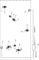
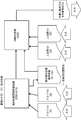
- FIG. 1 is a diagram for explaining a configuration of a measurement system 1000 according to the present embodiment.
- a plurality of distance measuring sensors 10.1-10 A state in which n (n: a natural number of 2 or more) is arranged is shown.
- n a natural number of 2 or more
- two distance sensors 10.1 and 10.2 are representatively shown.
- a measurement arithmetic device 100 is also arranged for executing target tracking and specific processing.
- the distance measuring sensor may be a measuring device that measures the distance between two points in a non-contact manner, but in the following, the distance measuring sensor 10.1-10.
- each n is described as being a laser range finder.
- humans p1-p7 are walking in a part of the shopping center in the predetermined observation area.
- pedestrians p1 and p2 are moving as one group, and pedestrians p3-p5 are also moving as one group.
- the measurement arithmetic device 100 is not particularly limited, but can be realized by a general-purpose computer, and the laser range finder 10.1-10. n is connected through an interface of a predetermined standard. In the example of FIG. 1, all the laser range finders 10.1-10. n is connected, but the processing may be shared by two or more computers connected by a network such as a LAN. In that case, for example, any one computer may function as a central computer.
- n laser range finders 10.1-10 in order to track an object in a predetermined observation region, n laser range finders 10.1-10.
- n is provided, this is merely an example. Therefore, the number of laser range finders is appropriately changed according to the size, shape, and position and number of obstacles.
- n is arranged at a position where a moving object in an observation area such as a building can be detected, and the laser range finder 10.1-10.
- each of n is at least two or more laser range finders 10.1-10. It arrange
- Laser range finder 10.1-10. n measures the distance for the object from the time it takes to irradiate the laser and reflect it back to the object. For example, a laser beam emitted from a transmitter (not shown) is reflected by a rotating mirror (not shown), and the front is scanned in a fan shape at a constant angle (for example, 0.5 degrees).
- laser range finder 10.1-10 The measurement range of n is indicated by a semicircular shape (fan shape) with a radius R. That is, the laser range finder 10.1-10.
- n When n is centered on the front direction, n can be measured within a predetermined distance (R) at a predetermined angle, for example, 90 °, for each of the left and right.
- the laser used is a class 1 laser in the Japanese Industrial Standards JIS C 6802 “Safety Standards for Laser Products” and is at a safe level that does not affect human eyes.
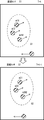
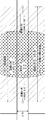
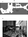
- FIG. 2 is a diagram showing an example of distance measurement data by LRF in a predetermined region to be observed as described above.
- the upper part 2a shows the raw data measured by the distance sensor
- the lower part 2b shows the detection result of the moving object except the fixed object as the background.
- the distance sensors are shown as circles or semicircles.
- the fixed object as the background is shown in gray
- the detected moving object is indicated by a circle
- the moving direction is indicated by a straight line added to the circle. Since an object that moves at the height of the human waist is detected, the moving object is estimated to be a person.
- an object identified as moving as a group in this measurement time step by a method as described later is surrounded by a dotted circle.
- a group that is considered to move as a group in the environment due to the social relationship of people is called a “social group”.
- FIG. 3 is a block diagram for explaining a hardware configuration of the measurement arithmetic device 100.
- the measurement arithmetic device 100 includes a drive device 52 that can read data recorded on the external recording medium 64, and a central processing device (CPU: Central Processing) Unit) 56 connected to a bus 66.
- ROM Read Only Memory
- RAM Random Access Memory
- nonvolatile storage device 54 nonvolatile storage device 54
- laser range finder 10.1-10 laser range finder 10.1-10.
- data input I / F data input interface
- the external recording medium 64 for example, an optical disk such as a CD-ROM or a DVD-ROM or a memory card can be used.
- the target recording medium is not limited to this as long as the device that realizes the function of the recording medium drive 52 is a device that can read data stored in a nonvolatile recording medium such as an optical disk or a flash memory.
- a device that realizes the function of the nonvolatile storage device 54 may be a magnetic storage device such as a hard disk or a flash memory as long as it can store data in a nonvolatile manner and can be accessed randomly. It is also possible to use a solid state drive (SSD) that uses a nonvolatile semiconductor memory such as a storage device.
- SSD solid state drive
- the main part of such a measurement calculation device 100 is realized by computer hardware and software executed by the CPU 56.
- such software is recorded by mask ROM, programmable ROM, or the like at the time of measurement and calculation device 100 manufacture.
- the software may be read into RAM 60 at the time of execution, or read from recording medium 64 by drive device 52. It may be configured to be temporarily stored in the nonvolatile storage device 54 and read to the RAM 60 at the time of execution.
- the server is temporarily copied from the server on the network to the nonvolatile storage device 54, read from the nonvolatile storage device 54 to the RAM 60, and executed by the CPU 56. There may be.
- the computer hardware itself and its operating principle shown in FIG. 3 are general. Accordingly, one of the most essential parts of the present invention is software stored in a recording medium such as the nonvolatile storage device 54.
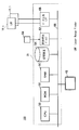
- FIG. 4 is a functional block diagram showing functions realized by the above-described CPU 56 executing software in the measurement arithmetic device 100 according to the present embodiment.
- the laser range finder 10.1-10 Based on the output (distance data) from n, the tracking module 5630 tracks the object (person). The tracking of the object is executed by estimating the position and speed of the object using a technique such as a particle filter.
- Such tracking processing of an object can be performed by a well-known method as disclosed in the following document, for example.
- the position and orientation of each of the plurality of distance sensors is set to a sensor comprising a plurality of distance sensors.
- a configuration of processing for calibration in the network coordinate system will be described.
- laser range finder 10.1-10 The distance measurement signal from n is controlled by the data capture processing unit 5602 and input as digital data, and the capture data recording processing unit 5604 sends the laser range finder to each storage device such as the nonvolatile storage device 54 for each laser range finder.
- Each storage device such as the nonvolatile storage device 54 for each laser range finder.
- time stamp the data indicating the time when the data is taken in under the control of the measurement arithmetic device 100 when acquiring the data in time series.
- the time stamp data is the laser range finder 10.1-10.
- n is stored in the nonvolatile storage device 54 in association with each of the distance measurement data from n.
- time step the time interval for determining whether or not a group candidate exists in the measurement target of each laser range finder.
- the time step will be described as being at the same timing as each time stamp is attached.
- the time step may be a predetermined multiple of the time interval of the time stamp.
- the measurement arithmetic device 100 further selects, for example, a moving object corresponding to a person from among measurement targets of each laser range finder based on time-series data stored in the storage device.
- a group comparison unit 5612 that identifies a group and calculates the relative position of each pair of laser range finders based on the position and orientation of the identified matching group, and for each matched group for each pair of laser range finders, By voting process, laser range finder
- a generalized Hough transform processing unit 5614 for acquiring a primary relative sensor position evaluation for the relative positional relationship of a and a pair of laser range finders corresponding to the primary relative sensor position evaluation by robust estimation.
- a constraint condition matrix described later is generated based on the position of the object commonly observed from each pair in which the position error is minimized.
- the position and orientation of each laser range finder in the network coordinate system is calibrated so that the position error in the defined coordinate system (hereinafter “network coordinate system”) is minimized, and the calibration result is stored in the storage device 54.
- network coordinate system the defined coordinate system
- the measurement arithmetic device 100 further aligns the position and orientation of each laser range finder with a floor map (map corresponding to the measurement region) based on the position and orientation of each laser range finder stored in the storage device 54. And an image output control unit 5640 for displaying the detected moving object in the global coordinate system.
- each laser range finder is assumed to be in a fixed position.
- usable data are current and distance scan data as a history (time series) from each distance sensor.
- the procedure for calibration is preferably a technique that enables non-invasiveness without interfering with the observed social environment.
- targets found naturally in the environment means that, for example, if one sensor is removed while data collection is in progress, the system can be quickly recalibrated with minimal effort and at any time. enable.
- the movement pattern of the pedestrian who moves through the environment is used as a feature for measuring the sensor position.
- Patent Document 2 Japanese Patent Laid-Open No. 2012-881357
- a method for automatic sensor calibration based on pedestrian observation is proposed.
- the observation is matched between the sensors by comparing the orbital shapes.
- This technique is effective for an environment in which the trajectory of walking changes remarkably according to movement, such as in an area having partial areas that are locally directed in different directions.
- it is not always effective to apply the above technique.
- the majority of trajectories are locally similar to straight lines and it is difficult to distinguish them based solely on trajectory shape.
- the observation matching procedure between the sensors is configured to reduce the calculation load.
- the calibration procedure of this embodiment (Pedestrian movement pattern)
- the feature of the movement pattern that appears in the movement of the pedestrian is used instead of using the movement trajectory of the pedestrian.
- the search space can be reduced in order to reduce the computational load when the number of pedestrians is large.
- the group is made up of people such as parents and children, groups of friends, lovers or teams of business colleagues, it means that the members are approaching regardless of the external forces involved in the walking flow. It can be identified by the fact that both group members stay within a certain range and adjust the walking speed.
- social groups are stable over time and provide an opportunity to filter time series data for better noise removal.
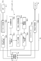
- FIG. 5 is a flowchart for explaining the flow of the calibration method of the present embodiment.
- the human position extraction unit 5608 uses the raw scan data and the background model from each sensor to correspond to the position of the moving object (which basically corresponds to the pedestrian position. , Referred to as “pedestrian position”), and relative pedestrian position data from each sensor is output (S100). However, typically this position data is noisy.
- Such extraction of the position of the person is executed for each distance measurement data corresponding to the time stamp, for example.
- the social group identification unit 5610 for pedestrian positions detected by each sensor at the same time (same time stamp), matches the degree of proximity of the pedestrian positions and the movement direction ( Based on the degree of motion direction coherence), social group candidates observed from each sensor are identified (S200).
- the group comparison unit 5612 standardizes the groups according to the direction of motion, compares the relative positions of the members, identifies matching (matching) group candidates, and is identified. Based on the position and orientation of the matching group candidates, a preliminary relative positional evaluation (“preliminary sensor offset hypothesis”) of each pair of laser rangefinders is calculated (S300).
- “match (match)” a group means that group candidates observed from a pair of laser range finders are identified as the same group.
- the generalized Hough transform processing unit 5614 uses a plurality of positions and orientations of the laser range finder pair in the local coordinates of the reference laser range finder when one of the laser range finder pairs is used as a reference.
- the “sensor offset hypothesis” is calculated by averaging the “preliminary sensor offset hypothesis” for the unique groups that are determined to be the same group over the time step. Then, the vote of the sensor offset hypothesis is accumulated for all the unique groups for the laser range finder pair in the bin set to the local coordinates, and the bin having the highest score is selected (S310). Therefore, the “sensor offset hypothesis” is expressed by the position and orientation of the other laser range finder in the local coordinates of the reference laser range finder.
- the sensor offset hypothesis corresponding to the bin having the highest score is the primary relative sensor position evaluation.
- Primary relative sensor position evaluation refers to a bin as described in detail below for each pair of laser range finders that commonly observe such unique groups based on the sensor offset hypothesis for each unique group. And is calculated for each pair of laser range finders.
- the RANSAC processing unit 5616 re-evaluates the relative position by excluding outliers for the object that is commonly observed for the pair of laser range finders corresponding to the primary relative sensor position evaluation by robust estimation.
- the secondary relative sensor position evaluation that minimizes the position error with respect to the object commonly observed from each pair is calculated.
- robust estimation the method of calculating the secondary relative sensor position evaluation by re-adjusting the relative position evaluation from the primary relative sensor position evaluation so as to minimize the influence of the error by excluding outliers, Other methods other than RANSAC may be used.
- the network position specifying unit 5620 determines the constraint described later based on the position of the positively-corresponding target object commonly observed from each pair in which the position error is minimized in the secondary relative sensor position evaluation. Generate a condition matrix to solve the constraint matrix using least squares minimization so that the error in the position of the object commonly observed from each pair is minimized.
- the position and orientation of the laser range finder are calibrated, and the calibration result is stored in the storage device 54 (S400).
- FIG. 6 is a diagram showing data actually observed by the laser range finder.
- the background scan is constructed to model a fixed part in the environment.
- the background area background area
- the background area is shown in gray, and two pedestrians are detected.
- a set of observation distances is collected for each scan angle over several scans, and the most frequently observed distance over the observation time is used to build the background model.
- each data scan is divided into segments in order to extract a human position.
- a median filter may be used to remove outliers and smooth the scan data.
- a range of a predetermined segment length for example, a segment between a width of 5 cm and 80 cm is considered as a candidate for a position where a person exists.
- the center position of the body is a function of the observed body width. It is determined.
- the position of the person is indicated by a circle for simplicity.
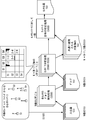
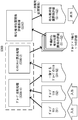
- FIG. 7 is a diagram in which the flowchart shown in FIG. 5 is rewritten as a functional block
- FIG. 8 is a diagram showing an example of data output by each functional block in FIG.
- a “person relative position list” (hereinafter“ person position list ”) includes a time stamp indicating a measured time and a laser range for one laser range finder.
- the local coordinates of the position of the pedestrian detected by the finder (here, polar coordinates (r, ⁇ )) are included.
- group candidates are detected for each laser range finder based on the person position list for the N laser range finders. This corresponds to the process of the social group identification unit 5610 of FIG. 4 or the process of step S200 of FIG.
- the detected group candidates are output as N group lists respectively corresponding to the laser range finder.
- the group list is detected in distance data corresponding to the same time stamp, for example.
- the “group list” includes a time stamp indicating a measured time and a detected group for one group (or a subgroup described later) for each laser range finder.
- of the moving speed of the group, and the position of each member from the geometric center of the group are included for m members.
- the center of the polar coordinate is the geometric center of the group as described above, for example, the center of gravity when each member is considered with the same weight can be used.
- the direction of the moving speed can be.
- a group commonly observed in the pair is specified based on the group list, and between the pairs of laser range finders.
- the relative positional relationship is specified.
- the position of the pedestrian observed in common from the pair of laser range finders is specified so that the position error is minimized by the specified relative positional relationship.
- the “list of commonly observed objects” includes a common observation in the local coordinates of one of the paired laser range finders for each commonly observed object.
- a set of the position coordinates of the object to be processed and the position coordinates of the same object in the local coordinates of the other laser range finder to be paired is included.
- a constraint matrix as described later is generated based on the “list of commonly observed objects”, and this constraint
- the calibration process is executed by finding the positions and orientations of the N laser range finders in the entire sensor network by solving the conditional expression based on the condition matrix by the method of least squares.
- This “configuration processing of the entire network” corresponds to the processing of the network location specifying unit 5620 in FIG. 4 or step S400 in FIG.
- a “sensor position list” indicating the position and orientation of each laser range finder in the entire sensor network is output.
- the “sensor position list” includes positions and directions in the entire sensor network for each laser range finder.
- “determining the position and direction in the entire sensor network” means, for example, when the position of any one distance sensor, for example, the first distance sensor is used as a reference, It means that all the relative positions and relative orientations of the distance sensors are determined. After that, by aligning the “position and direction of each distance sensor in the entire sensor network” determined in this way with a floor map or the like, the position of the object detected by each distance sensor is specified in global coordinates. Will be.
- a social group formed in the flow of pedestrians is adopted as a posture-invariant feature.
- Social groups can describe more features than individual pedestrian trajectories, and they are stable over time.
- This description vector uses the number n of members of the group and the absolute value of the motion vector
- the shape of the group can be described in a posture-invariant way as a list of its member positions. That is, it is represented by the position of each member with respect to the geometric center (center of gravity) of the group (or a subgroup described later).
- FIG. 9 is a flowchart for explaining the “group detection processing of each sensor” of FIG.
- the distance between the detected person and the person is a predetermined distance, for example, less than 1.5 m, and the direction of movement is aligned.
- the direction of movement is matched within a predetermined angle range (for example, within ⁇ 30 °)), and the set of pedestrians is identified as a social group.
- the CPU 56 advances the time step to be processed next and resets the group list (S2002).
- the CPU 56 sets the next person H in the “person position list” of the current processing target time step as a target (S2004), and the group candidate in which the person H has already been identified is within 1.5 m. It is determined whether the distance and the direction of movement coincide within ⁇ 30 ° (S2006).
- the CPU 56 adds the person H as a member of the corresponding group candidate in the current group list (S2008).
- the CPU 56 When the distance and the direction of movement satisfy the conditions (Yes in S2010), the CPU 56 generates a new group candidate in the current group list (S2012).
- the CPU 56 calculates the subgroup of the group and the description vector of each subgroup for each group listed in the group list (A in S2020).
- the CPU 56 outputs a group list for each laser range finder for all time steps.
- the group list is a list of all groups observed for each distance sensor at each time step.
- Some members of the group may be shielded (called occlusion) from the view range of the laser rangefinder by others.
- a group may be observed to have three members for one laser range finder, but only two people for another laser range finder.
- the CPU 56 enumerates all the subgroups constituting the observed group for use as a candidate for matching between the pair of laser range finders.
- FIG. 10 is a diagram showing subgroups corresponding to possible occlusions and group description vectors.
- FIG. 10A shows the groups observed by the laser range finder S1
- FIG. 10B shows an enumeration of possible subgroups of the observed groups.
- a subgroup for the group is also included.
- a subgroup of a certain group and another group, or a subgroup of a certain group and a subgroup of another group are matched, they are referred to as “a group is matched”.
- CPU56 calculates the description vector mentioned above about each subgroup.
- FIG. 11 is a functional block diagram for explaining the “sensor pair analysis process” shown in FIG.
- FIG. 11 exemplarily shows a process for a pair of the laser range finder S1 and the laser range finder S2.
- a group list for laser range finder S1 and a group list for laser range finder S2 are input, and a rough relative between laser range finder S1 and laser range finder S2 is input. Outputs the result of positional relationship evaluation.
- the “relative positional relationship evaluation process” corresponds to steps S300 to S310 in FIG.
- the result of “rough relative positional relationship evaluation” is referred to as “first relative positional relationship”.
- the primary relative positional relationship, the human position list for the laser range finder S1, and the human position list for the laser range finder S2 are input, and a “list of commonly observed objects” is output.
- the RANSAC process corresponds to the process of the RANSAC processing unit 5616 in FIG. 4 or the process of step S320 in FIG.
- FIG. 12 is a functional block diagram for explaining the relative positional relationship evaluation process shown in FIG.
- the group list for the laser range finder S1 and the group list for the laser range finder S2 are input, and the “matching group list” is set for the pair of the laser range finder S1 and the laser range finder S2. Is output.
- the sensor offset calculation process (S300-2) outputs a “preliminary evaluation of relative positional relationship” for a laser range finder pair at each time step, with a list of matching groups as an input.
- “preliminary evaluation of relative positional relationship” is calculated for each pair of matching groups.
- the “relative positional relationship” is not particularly limited, but means the position and orientation of another laser range finder in the coordinate system of the reference laser range finder with reference to one position of the pair of laser range finder. To do. In this sense, “relative positional relationship” is also referred to as “sensor offset”.
- the combination of the group comparison process (S300-1) and the sensor offset calculation process (S300-2) corresponds to step S300 in FIG.
- the coarse relative positional relationship evaluation process inputs “preliminary relative positional relationship evaluation” and outputs the result of “rough relative positional relationship evaluation”, that is, “first relative positional relationship”.
- FIG. 13 is a flowchart for explaining the process performed by the CPU 56 in the group comparison process (S300-1).
- FIG. 13 illustrates a process of comparing groups for a pair of distance sensor S1 and distance sensor S2.
- each group in the group list of the distance sensor S1 is compared with each group in the group list of the distance sensor S2. Such a comparison is performed in all distance sensors.
- the group description vector is composed of the number of members n, the velocity vector magnitude
- filtering may be performed based not only on the number of people in the group but also on the magnitude of the difference in group speed, that is, on the condition of
- Vthreshold is a predetermined threshold value.
- both a working variable for specifying a group when selecting a group and a working variable for specifying a member in the group are set to 0.
- CPU 56 receives the group list for laser range finder S1 and the group list for laser range finder S2, and performs the comparison process for the next group ( S3102).
- the groups to be compared are group G1 and group G2.
- the group includes subgroups.
- the CPU 56 determines whether the number of members of the group to be compared is equal (S3104). If not equal, the process returns to step S3102.
- the numbers when expressed in polar coordinates with the group motion direction as a reference (X axis), for example, the numbers are associated with the members of the group counterclockwise from the X axis. For the number members, the distance shall be calculated.
- d thresold is a predetermined threshold value.
- the CPU 56 determines whether there is a next member in the group (S3110).
- step S3106 If there is a next member, the process returns to step S3106.
- a number is associated with a member of the group” If there is an error in detection, this numbering may be shifted. Therefore, for the two groups, a pair of closest members may be determined first, and numbering may be performed starting from the closest member.
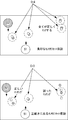
- FIG. 14 is a diagram showing an example of two groups observed from two different distance sensors, “L” and “N” viewpoints.
- FIG. 15 is a diagram showing the description vector of the group observed from each distance sensor shown in FIG.
- FIG. 15 shows a state in which subgroups are listed for group 2 in which the number of groups observed from the distance sensor L is three.
- Group 3 having two persons observed from the distance sensor N can be matched with “subgroup 2c” of “group 2” having three persons observed by the distance sensor L.
- FIG. 16 is a flowchart for explaining the process of the sensor offset calculation process (S300-2).
- the observation S1 G1 of a certain group G1 observed by the distance sensor S1 and the observation S2 G1 of the same group observed by the distance sensor S2 are in the form of a transformation matrix S1 S2 H G1.
- the conversion matrix S1 S2 H G1 is based on the fact that the same group G1 is observed from the distance sensor S1 and the distance sensor S2, and based on the position of the sensor S1, the local coordinates of the sensor S1 Corresponds to a matrix that converts to local coordinates.
- the CPU 56 observes a certain group of observations S1 G1 observed by the distance sensor S1 and an observation S2 of the same group observed by the sensor S2.
- the rotational offset S1 ⁇ S2 is calculated as the difference between the motion directions S1 ⁇ G1 and S1 ⁇ G1 (S3202).
- the CPU 56 calculates the translational offset between the two sensors as a difference between the group center positions ( S1 x G1 , S1 y G1 ) and ( S2 x G1 , S2 y G1 ) (S3204).
- the calculated conversion matrix S1 S2 H G1 is output as an evaluation of a preliminary relative positional relationship between the sensor S1 and the sensor S2 (“preliminary sensor offset hypothesis”). Can be identified.
- a discrete accumulator grid (a grid-like grid for voting processing) is placed in the (x, y, ⁇ ) space, which is the local coordinates of the distance sensor S1, with the distance sensor S1 as a reference. Defined for each social group matching identified in the preliminary relative positional relationship determined by the group ("Preliminary Sensor Offset Hypothesis"). Perform voting on the corresponding bin.
- FIG. 17 is a functional block diagram for explaining the processing of “coarse relative positional relationship evaluation processing (S310)”.
- a preliminary relative positional relationship evaluation (“preliminary sensor offset hypothesis”) is used as an input, and a procedure described later is performed. , Group candidates moving as the same unique group over a plurality of time steps are identified.
- the sensor offset hypothesis in local coordinates is calculated by averaging the preliminary relative position assessment at each time step over multiple time steps for this unique group. That is, the “sensor offset hypothesis in local coordinates” indicates the position and direction of the distance sensor S2 averaged for the unique group in the (x, y, ⁇ ) space, and the corresponding conversion matrix is represented by S1 S2 H ⁇ Gn .
- the likelihood indicating the correctness of the sensor offset hypothesis at each local coordinate is calculated as the consistency metric C (x, y, ⁇ ).
- the consistency metric C (x, y, ⁇ ) is also based on the observation history of the two sensors, as will be explained later, also using the human position lists of the distance sensors S1 and S2. Is calculated.
- a unique group is specified by matching between group candidates at each time step. For example, the movement trajectory of each pedestrian is obtained by a known method, and then the movement is performed. A unique group may be specified according to the degree of proximity of the trajectory.
- FIG. 18 is a diagram for explaining the concept of “unique group matching processing (S3102)”.
- the groups (subgroups) G1 and G2 are determined to be the same unique group when the following conditions are satisfied.
- the member m i G1 is closest to the member m i G2 (the distance is closest).
- the distance between the member mi G1 and the member mi G2 is equal to or less than a predetermined threshold.
- the same unique group is extracted, and the “sensor offset hypothesis in local coordinates” is calculated by the averaging process over the movement history of this unique group.
- FIG. 19 is a diagram for explaining the concept of “consistency metric calculation processing (S3104)”.
- the calculation is performed by counting how many positions of the objects that can be said to overlap each other.
- the motion directions are within the threshold angle, that is,
- a kd tree may be used for this search for computational efficiency.
- the distance from the position S1 p 2 (i) to the nearest position S1 p 1 (j) and the second closest proximity position S1 p 1 (k) are calculated.
- the ratio of the following Euclidean distance is a predetermined value, for example, 0.8 or less, it is considered that the closest position is matched, that is, if the following expression holds, the two positions are , It is determined that they are overlapping (matching).
- the consistency metric C (x, y, ⁇ ) was observed by the distance sensor S1 except for the observation position included in the group Gn itself used to calculate the transformation matrix S1 S2 H ′ Gn . It is defined as the total number of positions that are matched between the positions S1 p 1 and distance position obtained by converting the observed position sensor S1 S1 p 2.
- FIG. 20 is a diagram for explaining the concept of “voting process to accumulator grid (S3106)”.
- the “sensor offset hypothesis in local coordinates” is expressed only in (x, y) coordinates in (x, y, ⁇ ) space.
- Bin as shown in FIG. 20 is set in the (x, y) space.
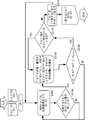
- FIG. 21 is a flowchart for explaining the RANSAC process (S320) shown in FIG.
- a sensor pair Is considered to have a result of "rough relative position evaluation" (coarse sensor offset hypothesis) that can be trusted to some extent.
- the RANSAC Random Sample Consensus
- the purpose of the RANSAC process is to further eliminate the matching of these errors by re-adjusting the sensor offset hypothesis and the corresponding set of observation pairs.
- the conversion matrix representing the best “coarse sensor offset hypothesis” is represented by H.
- the conversion matrix H corresponds to the distance sensor pair S1 and S2
- the local coordinate position of the distance sensor S2 is converted to the local coordinate position of the distance sensor S1 by using the conversion matrix H.
- the CPU 56 calculates a conversion matrix H for each sensor pair based on the best “rough sensor offset hypothesis” (S3302).
- the CPU 56 randomly selects a subset for a predetermined number of people from the human position list for one distance sensor S1 in the sensor pair that is the object of the current calculation (S3304).
- the CPU 56 obtains the position of the person observed by the distance sensor S2 as a position in the local coordinate system for the distance sensor S1 using the matrix H, and for each position of the selected subset of the person position list for the distance sensor S1. Then, the position of the closest person is extracted as a distance from the person position list for the distance sensor S2 (S3306). A pair of human positions extracted in this way is called a “commonly observed object”.
- the CPU 56 calculates a sensor offset hypothesis (represented by a conversion matrix H ′) so as to best match each position of the “commonly observed object” (S3308).
- the conversion matrix H ′ can be calculated using the least square method or the like so that the error in the position of the “commonly observed object” is minimized by using the conversion in the conversion matrix H ′. .
- the CPU 56 uses the conversion matrix H ′ to determine whether the closest matching is true or not (outlier: outlier). (S3310).
- whether or not it is the closest match can be determined by the same procedure as that used in calculating the consistency metric. Alternatively, the closest matching may be determined simply by determining whether the difference in the distance between the objects is smaller than a predetermined threshold.
- the CPU 56 uses only the observation pairs that are assumed to be the positive correspondence, and the error of the position of the “commonly observed object” of the positive correspondence that is converted by the conversion matrix H ′′ for these positive correspondence pairs. (S3312). Further, a position error sum ⁇ for a positive-corresponding observation pair calculated using the conversion matrix H ′′ is calculated. .
- step S3304 it is determined whether the process from step S3304 to S3312 has been repeated a predetermined number of times (S3314). If the process has not been repeated a predetermined number of times, the process returns to step S3304.
- the CPU 56 determines a pair of positive observation pairs with the smallest position error sum ⁇ as “a common observation target object”. List ".
- the sensor offset hypothesis represented by the conversion matrix H ” that minimizes the sum ⁇ of position errors is referred to as“ secondary relative positional relationship ”.
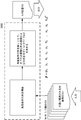
- FIG. 22 is a functional block diagram for explaining the “calibration process for the entire network” shown in FIG.
- the “calibration process of the entire network” is performed by combining the position of “a pair of observation pairs corresponding to the smallest position error sum ⁇ ” obtained by the RANSAC process into a constraint matrix for each sensor pair. Solve the matrix for the relative positions of all sensors in the network.
- the position of the nth distance sensor in the network coordinate system is (xn, yn) and the direction is ⁇ n.
- the transformation from the local coordinate system of the distance sensor n to the network coordinate system represents the rotation of ⁇ n and ⁇ xn and represented by the homogeneous transformation matrix of the following equation (1): -Requires translational motion of yn.
- the origin of the network coordinate system is assumed to be the position of the distance sensor 1, for example.
- the position errors can be summarized as follows for the m common observation positions.
- the shared observation matrix is defined as follows.
- the sensor position in the network coordinate system obtained as described above has an indefinite relationship with respect to the direction and position with the map of the actual floor. Therefore, the floor map or the photograph from the upper surface of the floor and the sensor position in the above network coordinate system are overlapped on the display, for example, and finally matched manually, The map and the position of each distance sensor in the network coordinate system can be matched. (Evaluation experiment) In order to evaluate the performance of the algorithm compared to field survey information in a control environment, the accuracy of the sensor location was measured.
- FIG. 23 is a floor map of a place where the positioning accuracy of the sensor position has been confirmed.
- the distance sensor was installed as accurately as possible at the planned position.
- the reference pole was placed at the origin and the sensor was manually rotated until the reference pole coincided with the center scan point detected by the laser range finder.
- the exact offset of the sensor was measured using a high precision laser ranging device. Also, the sensor angle was fine tuned with software to align the reference pole and wall detection.
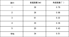
- FIG. 24 is a diagram showing the results of such a trial.
- the position of the center of gravity calculated in all observations from different sensors is denoted by p ⁇ (i) (t), and the evaluation position of the person i observed by the sensor s at time t is denoted by p s (i) (t).
- the number S (i) (t) of sensors that can observe a person i at a certain position depends on its arrangement and dynamically occurring occlusion.
- Equation 12 The average error ⁇ from the center of gravity is calculated as shown in Equation 12 below.
- a set of reference pedestrians was obtained by manually identifying the corresponding trajectories from different sensors. 150 reference pedestrians were identified for each environment.
- ⁇ (i) (t) was evaluated at each time step when the pedestrian was observed simultaneously by at least two sensors.
- the space was divided into grids with a predetermined resolution.
- Each grid is assigned an average error ⁇ (i) (t) over all data locations whose centroids are present in the grid, and the results are shown below for each environment.
- the comparison also included accuracy results for manual calibration with the best effort based on visual inspection of the scan data. That is the typical calibration accuracy available before developing this technique.
- (result) Linear corridor
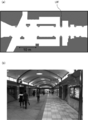
- the first environment analyzed was a corridor of Diamall Osaka approximately 50m long and 7m wide.
- FIG. 25 is a top view (FIG. 25 (a)) and a photograph (FIG. 25 (b)) of such a first environment.
- Deer Mall Osaka is an underground shopping district located between several train and subway stations in Osaka.
- This environment is a geometrically simple area in which areas covered by 16 sensors arranged along a straight corridor (indicated by a semicircle in FIG. 25A) overlap well.
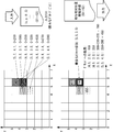
- FIG. 26 is a diagram showing the average error on all grids and the result of calibration accuracy.
- FIG. 26 (a) shows the pedestrian trajectory used in Diamor's accuracy analysis
- FIG. 26 (b) shows the error in space with manual calibration
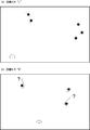
- FIG. 27 is a top view (FIG. 27 (a)) and a photograph (FIG. 27 (b)) of a place adopted as the second environment.
- the second environment is the Asia Pacific Trade Center (ATC), which is a complex of retail and wholesale trade of Osaka Waterfront.
- ATC Asia Pacific Trade Center
- This environment consisted of a corridor connected to a large atrium space, which was a space having a length of 60 m and a width of 25 m or more at its widest point.
- the sensor network consisted of 19 sensors.
- FIG. 28 is a diagram showing a calibration accuracy result together with an average error on all grids.
- FIG. 28 (a) shows the pedestrian trajectory used in the ATC accuracy analysis
- FIG. 28 (b) shows the error in space with manual calibration
- FIG. 28 (c) Indicates the error in space from automatic calibration.
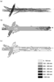
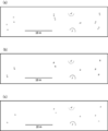
- FIG. 29 is a diagram showing the relative effectiveness of each step of the algorithm.
- FIG. 29A corresponds to after the Hough transform step
- FIG. 29B corresponds to the RANSAC process
- FIG. 29C corresponds to the final calibration.
- Fig. 4 shows an alignment of human positions detected by two sensors within one time frame based on a sensor offset hypothesis.
- each sensor offset hypothesis is used to generate a set of matches between human observations by a sensor pair, and a set of human observations generates a constraint matrix. In the end it will be used.
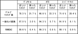
- Such confusion matrices were calculated for group matching, generalized Hough transform and RANSAC based on another set of reference pedestrian field survey trajectories taken from the data set used to perform the calibration.
- FIG. 30 is a diagram showing the confusion matrix evaluated in each of the first to third environments.
- each processing step contributes to the accuracy of the final calibration, and essentially reduces the number of false positives.
- the calibration apparatus when a plurality of distance sensors are installed in a certain area, for example, a physical target is manually placed in the environment. It is possible to reduce the workload for calibrating the position and orientation of each distance sensor, such as aligning the distance sensors.
- the shapes of the movement trajectories of the people are all similar, and an environment in which a plurality of people are walking at the same time. Even so, it is possible to calibrate the position and direction of the distance sensor.
- Laser range finder 52 drive device, 54 non-volatile storage device, 56 CPU, 58 ROM, 60 RAM, 64 external recording medium, 66 bus, 100 measurement computing device, 5602 data capture processing unit, 5604 capture data recording processing unit, 5608 Human location extraction unit, 5610 Social group identification unit, 5612 Group comparison unit, 5614 Generalized Hough transform processing unit, 5616 RANSAC processing unit, 5620 Network location specifying unit.
Landscapes
- Physics & Mathematics (AREA)
- Engineering & Computer Science (AREA)
- Electromagnetism (AREA)
- Computer Networks & Wireless Communication (AREA)
- General Physics & Mathematics (AREA)
- Radar, Positioning & Navigation (AREA)
- Remote Sensing (AREA)
- Optical Radar Systems And Details Thereof (AREA)
- Traffic Control Systems (AREA)
Priority Applications (2)
| Application Number | Priority Date | Filing Date | Title |
|---|---|---|---|
| CN201480071352.4A CN105874350B (zh) | 2013-12-27 | 2014-12-24 | 校准装置、校准方法及校准程序 |
| US15/192,118 US10324172B2 (en) | 2013-12-27 | 2016-06-24 | Calibration apparatus, calibration method and calibration program |
Applications Claiming Priority (2)
| Application Number | Priority Date | Filing Date | Title |
|---|---|---|---|
| JP2013273079A JP5950122B2 (ja) | 2013-12-27 | 2013-12-27 | キャリブレーション装置、キャリブレーション方法およびキャリブレーションプログラム |
| JP2013-273079 | 2013-12-27 |
Related Child Applications (1)
| Application Number | Title | Priority Date | Filing Date |
|---|---|---|---|
| US15/192,118 Continuation US10324172B2 (en) | 2013-12-27 | 2016-06-24 | Calibration apparatus, calibration method and calibration program |
Publications (1)
| Publication Number | Publication Date |
|---|---|
| WO2015098971A1 true WO2015098971A1 (ja) | 2015-07-02 |
Family
ID=53478821
Family Applications (1)
| Application Number | Title | Priority Date | Filing Date |
|---|---|---|---|
| PCT/JP2014/084166 Ceased WO2015098971A1 (ja) | 2013-12-27 | 2014-12-24 | キャリブレーション装置、キャリブレーション方法およびキャリブレーションプログラム |
Country Status (4)
| Country | Link |
|---|---|
| US (1) | US10324172B2 (enExample) |
| JP (1) | JP5950122B2 (enExample) |
| CN (1) | CN105874350B (enExample) |
| WO (1) | WO2015098971A1 (enExample) |
Cited By (2)
| Publication number | Priority date | Publication date | Assignee | Title |
|---|---|---|---|---|
| CN113092681A (zh) * | 2021-04-02 | 2021-07-09 | 河北先河环保科技股份有限公司 | 用于网格化监控网络的传感器配对方法及系统 |
| CN114510516A (zh) * | 2022-02-21 | 2022-05-17 | 重庆大学 | 一种多传感器数据时间标签对齐方法 |
Families Citing this family (23)
| Publication number | Priority date | Publication date | Assignee | Title |
|---|---|---|---|---|
| AU2015234329A1 (en) * | 2015-09-30 | 2017-04-13 | Canon Kabushiki Kaisha | Method, system and apparatus for processing an image |
| JP6746050B2 (ja) * | 2015-11-25 | 2020-08-26 | 株式会社国際電気通信基礎技術研究所 | キャリブレーション装置、キャリブレーション方法およびキャリブレーションプログラム |
| JP6754574B2 (ja) * | 2016-01-18 | 2020-09-16 | 株式会社日立情報通信エンジニアリング | 移動体計測システム、及び計測対象の領域における人物の数を特定する方法 |
| KR101932041B1 (ko) * | 2017-03-02 | 2018-12-24 | 충북대학교 산학협력단 | 듀얼 라이다 센서 캘리브레이션 방법 및 장치 |
| CN107229043B (zh) * | 2017-05-22 | 2019-04-09 | 中国农业科学院农业资源与农业区划研究所 | 一种距离传感器外参数标定方法和系统 |
| US20190004160A1 (en) * | 2017-06-30 | 2019-01-03 | Delphi Technologies, Inc. | Lidar sensor alignment system |
| CN111868564B (zh) * | 2018-03-22 | 2024-05-07 | 日立安斯泰莫株式会社 | 物体识别装置 |
| US10823845B2 (en) * | 2018-06-24 | 2020-11-03 | Mitsubishi Electric Research Laboratories, Inc. | System and method for robust sensor localization based on euclidean distance matrix |
| WO2020010043A1 (en) * | 2018-07-06 | 2020-01-09 | Brain Corporation | Systems, methods and apparatuses for calibrating sensors mounted on a device |
| CA3110691A1 (en) | 2018-08-24 | 2020-02-27 | Lutron Technology Company Llc | Occupant detection device |
| CN109059902B (zh) | 2018-09-07 | 2021-05-28 | 百度在线网络技术(北京)有限公司 | 相对位姿确定方法、装置、设备和介质 |
| EP3985347B1 (en) | 2019-06-17 | 2024-04-03 | OMRON Corporation | Device, method and program for measuring point clouds |
| CN110319853A (zh) * | 2019-07-19 | 2019-10-11 | 广州市番通汽车检测有限公司 | 一种方便校准的汽车姿势测量系统 |
| JP7363545B2 (ja) * | 2020-02-05 | 2023-10-18 | 沖電気工業株式会社 | キャリブレーション判定結果提示装置、キャリブレーション判定結果提示方法及びプログラム |
| DE102020202800A1 (de) * | 2020-03-05 | 2021-09-09 | Robert Bosch Gesellschaft mit beschränkter Haftung | Ermitteln von Reichweiteneinschränkungen für LIDAR-Vorrichtungen |
| WO2021220331A1 (ja) * | 2020-04-27 | 2021-11-04 | 株式会社日立産機システム | 移動体システム |
| CN111457943A (zh) * | 2020-05-13 | 2020-07-28 | 深圳市中联讯科技有限公司 | 传感器自动校准设备及校准方法 |
| JP7286586B2 (ja) * | 2020-05-14 | 2023-06-05 | 株式会社日立エルジーデータストレージ | 測距システム及び測距センサのキャリブレーション方法 |
| CN112362084A (zh) * | 2020-11-23 | 2021-02-12 | 北京三快在线科技有限公司 | 一种数据标定方法、装置及数据标定系统 |
| CN112729317B (zh) * | 2020-12-17 | 2023-09-19 | 大陆投资(中国)有限公司 | 用于定位车辆的方法和车载系统 |
| CN113298194B (zh) * | 2021-07-26 | 2021-10-19 | 中大检测(湖南)股份有限公司 | 一种基于多传感器的数据融合方法、系统及存储介质 |
| CN114166133B (zh) * | 2021-11-24 | 2023-05-23 | 岚图汽车科技有限公司 | 一种高度传感器标定方法、装置、设备及可读存储介质 |
| JP2023159835A (ja) * | 2022-04-20 | 2023-11-01 | 株式会社日立エルジーデータストレージ | 測距システム及び測距センサのキャリブレーション方法 |
Citations (3)
| Publication number | Priority date | Publication date | Assignee | Title |
|---|---|---|---|---|
| JP2010127650A (ja) * | 2008-11-25 | 2010-06-10 | Nippon Telegr & Teleph Corp <Ntt> | 移動体位置推定システムと移動体位置推定方法及び移動体位置推定プログラム |
| JP2012088135A (ja) * | 2010-10-19 | 2012-05-10 | Advanced Telecommunication Research Institute International | 距離センサのキャリブレーション装置、キャリブレーションプログラムおよびキャリブレーション方法 |
| JP2013073459A (ja) * | 2011-09-28 | 2013-04-22 | Oki Electric Ind Co Ltd | 画像処理装置、画像処理方法、プログラム、および画像処理システム |
Family Cites Families (6)
| Publication number | Priority date | Publication date | Assignee | Title |
|---|---|---|---|---|
| US5793483A (en) * | 1996-02-07 | 1998-08-11 | Visidyne, Inc. | Optical measurement system |
| US6522288B1 (en) * | 2002-01-09 | 2003-02-18 | M/A-Com, Inc. | Method and apparatus for determining location of objects based on range readings from multiple sensors |
| US7433021B2 (en) * | 2004-08-10 | 2008-10-07 | Joseph Saltsman | Stereoscopic targeting, tracking and navigation device, system and method |
| WO2010132791A1 (en) * | 2009-05-15 | 2010-11-18 | Purdue Research Foundation | Calibration of large camera networks |
| DE112010005572T5 (de) * | 2010-05-19 | 2013-02-28 | Mitsubishi Electric Corporation | Fahrzeug-Rückansicht-Überwachungsvorrichtung |
| US10061028B2 (en) * | 2013-09-05 | 2018-08-28 | Texas Instruments Incorporated | Time-of-flight (TOF) assisted structured light imaging |
-
2013
- 2013-12-27 JP JP2013273079A patent/JP5950122B2/ja active Active
-
2014
- 2014-12-24 WO PCT/JP2014/084166 patent/WO2015098971A1/ja not_active Ceased
- 2014-12-24 CN CN201480071352.4A patent/CN105874350B/zh active Active
-
2016
- 2016-06-24 US US15/192,118 patent/US10324172B2/en active Active
Patent Citations (3)
| Publication number | Priority date | Publication date | Assignee | Title |
|---|---|---|---|---|
| JP2010127650A (ja) * | 2008-11-25 | 2010-06-10 | Nippon Telegr & Teleph Corp <Ntt> | 移動体位置推定システムと移動体位置推定方法及び移動体位置推定プログラム |
| JP2012088135A (ja) * | 2010-10-19 | 2012-05-10 | Advanced Telecommunication Research Institute International | 距離センサのキャリブレーション装置、キャリブレーションプログラムおよびキャリブレーション方法 |
| JP2013073459A (ja) * | 2011-09-28 | 2013-04-22 | Oki Electric Ind Co Ltd | 画像処理装置、画像処理方法、プログラム、および画像処理システム |
Cited By (3)
| Publication number | Priority date | Publication date | Assignee | Title |
|---|---|---|---|---|
| CN113092681A (zh) * | 2021-04-02 | 2021-07-09 | 河北先河环保科技股份有限公司 | 用于网格化监控网络的传感器配对方法及系统 |
| CN113092681B (zh) * | 2021-04-02 | 2023-01-17 | 河北先河环保科技股份有限公司 | 用于网格化监控网络的传感器配对方法及系统 |
| CN114510516A (zh) * | 2022-02-21 | 2022-05-17 | 重庆大学 | 一种多传感器数据时间标签对齐方法 |
Also Published As
| Publication number | Publication date |
|---|---|
| JP2015127664A (ja) | 2015-07-09 |
| CN105874350A (zh) | 2016-08-17 |
| CN105874350B (zh) | 2018-08-28 |
| US10324172B2 (en) | 2019-06-18 |
| US20160356882A1 (en) | 2016-12-08 |
| JP5950122B2 (ja) | 2016-07-13 |
Similar Documents
| Publication | Publication Date | Title |
|---|---|---|
| JP5950122B2 (ja) | キャリブレーション装置、キャリブレーション方法およびキャリブレーションプログラム | |
| Yousif et al. | An overview to visual odometry and visual SLAM: Applications to mobile robotics | |
| CN110782483B (zh) | 基于分布式相机网络的多视图多目标跟踪方法及系统 | |
| Lindstrom et al. | Detecting and tracking moving objects from a mobile platform using a laser range scanner | |
| JP5746477B2 (ja) | モデル生成装置、3次元計測装置、それらの制御方法及びプログラム | |
| US10636168B2 (en) | Image processing apparatus, method, and program | |
| US8831778B2 (en) | Method of accurate mapping with mobile robots | |
| JP5671281B2 (ja) | 位置姿勢計測装置、位置姿勢計測装置の制御方法及びプログラム | |
| US8965114B2 (en) | Object recognition apparatus, object recognition method, learning apparatus, learning method, storage medium and information processing system | |
| JP6746050B2 (ja) | キャリブレーション装置、キャリブレーション方法およびキャリブレーションプログラム | |
| US20120044355A1 (en) | Calibration of Wi-Fi Localization from Video Localization | |
| JP6221390B2 (ja) | 画像処理装置、プログラム、および画像処理方法 | |
| Zhang et al. | Single camera visual odometry based on random finite set statistics | |
| Tamjidi et al. | 6-DOF pose estimation of a portable navigation aid for the visually impaired | |
| JP5976089B2 (ja) | 位置姿勢計測装置、位置姿勢計測方法、およびプログラム | |
| Ruotsalainen et al. | Visual-aided two-dimensional pedestrian indoor navigation with a smartphone | |
| Glas et al. | SNAPCAT-3D: Calibrating networks of 3D range sensors for pedestrian tracking | |
| Knyaz et al. | Robust object tracking techniques for vision-based 3D motion analysis applications | |
| Utz et al. | Improving vision-based self-localization | |
| Glas et al. | Automatic position calibration and sensor displacement detection for networks of laser range finders for human tracking | |
| Dushepa | A learning-based approach for rigid image registration accuracy estimation | |
| Raju et al. | An Improved and Enhanced Depth Map Approach for Obstacle Detection in Unknown Environments for Reactive Autonomous Mobile Robots | |
| Kirnos et al. | Landmarks Detection by Contour Analysis in the Problem of SLAM. | |
| US20230260149A1 (en) | Position-posture estimation device, position-posture estimation method, and storage medium storing program | |
| Prozorov et al. | Self-localization of mobile robot in unknown environment |
Legal Events
| Date | Code | Title | Description |
|---|---|---|---|
| 121 | Ep: the epo has been informed by wipo that ep was designated in this application |
Ref document number: 14875048 Country of ref document: EP Kind code of ref document: A1 |
|
| NENP | Non-entry into the national phase |
Ref country code: DE |
|
| 122 | Ep: pct application non-entry in european phase |
Ref document number: 14875048 Country of ref document: EP Kind code of ref document: A1 |