WO2015098294A1 - 硬度可変アクチュエータ - Google Patents
硬度可変アクチュエータ Download PDFInfo
- Publication number
- WO2015098294A1 WO2015098294A1 PCT/JP2014/079234 JP2014079234W WO2015098294A1 WO 2015098294 A1 WO2015098294 A1 WO 2015098294A1 JP 2014079234 W JP2014079234 W JP 2014079234W WO 2015098294 A1 WO2015098294 A1 WO 2015098294A1
- Authority
- WO
- WIPO (PCT)
- Prior art keywords
- electrode
- flexible member
- voltage
- hardness
- variable
- Prior art date
- Legal status (The legal status is an assumption and is not a legal conclusion. Google has not performed a legal analysis and makes no representation as to the accuracy of the status listed.)
- Ceased
Links
Images




Classifications
-
- A—HUMAN NECESSITIES
- A61—MEDICAL OR VETERINARY SCIENCE; HYGIENE
- A61B—DIAGNOSIS; SURGERY; IDENTIFICATION
- A61B1/00—Instruments for performing medical examinations of the interior of cavities or tubes of the body by visual or photographical inspection, e.g. endoscopes; Illuminating arrangements therefor
- A61B1/00064—Constructional details of the endoscope body
- A61B1/00071—Insertion part of the endoscope body
- A61B1/00078—Insertion part of the endoscope body with stiffening means
-
- A—HUMAN NECESSITIES
- A61—MEDICAL OR VETERINARY SCIENCE; HYGIENE
- A61B—DIAGNOSIS; SURGERY; IDENTIFICATION
- A61B1/00—Instruments for performing medical examinations of the interior of cavities or tubes of the body by visual or photographical inspection, e.g. endoscopes; Illuminating arrangements therefor
- A61B1/00064—Constructional details of the endoscope body
- A61B1/0011—Manufacturing of endoscope parts
-
- A—HUMAN NECESSITIES
- A61—MEDICAL OR VETERINARY SCIENCE; HYGIENE
- A61B—DIAGNOSIS; SURGERY; IDENTIFICATION
- A61B1/00—Instruments for performing medical examinations of the interior of cavities or tubes of the body by visual or photographical inspection, e.g. endoscopes; Illuminating arrangements therefor
- A61B1/005—Flexible endoscopes
- A61B1/009—Flexible endoscopes with bending or curvature detection of the insertion part
-
- F—MECHANICAL ENGINEERING; LIGHTING; HEATING; WEAPONS; BLASTING
- F16—ENGINEERING ELEMENTS AND UNITS; GENERAL MEASURES FOR PRODUCING AND MAINTAINING EFFECTIVE FUNCTIONING OF MACHINES OR INSTALLATIONS; THERMAL INSULATION IN GENERAL
- F16L—PIPES; JOINTS OR FITTINGS FOR PIPES; SUPPORTS FOR PIPES, CABLES OR PROTECTIVE TUBING; MEANS FOR THERMAL INSULATION IN GENERAL
- F16L55/00—Devices or appurtenances for use in, or in connection with, pipes or pipe systems
-
- G—PHYSICS
- G02—OPTICS
- G02B—OPTICAL ELEMENTS, SYSTEMS OR APPARATUS
- G02B23/00—Telescopes, e.g. binoculars; Periscopes; Instruments for viewing the inside of hollow bodies; Viewfinders; Optical aiming or sighting devices
- G02B23/24—Instruments or systems for viewing the inside of hollow bodies, e.g. fibrescopes
- G02B23/2476—Non-optical details, e.g. housings, mountings, supports
Definitions
- the present invention relates to a variable hardness actuator capable of changing the rigidity against a bending force.
- variable hardness actuator that can change the rigidity of a member with respect to a bending force has been proposed in the past, and as an example, it is used to improve insertability in the field of endoscopes.
- the hardness is changed by changing the compression state of the close coil spring by pulling the wire attached to the tip of the close coil spring.
- a hardness adjusting device is described.
- this publication describes a technique for reducing the force by providing an elastic body in the wire pulling mechanism in consideration of the point that a large force is required for the operation when pulling the wire. Specifically, using a torsion spring or a spring as an elastic body, the traction torque required for traction is shifted to the negative side, but a portion where the traction torque becomes negative also occurs. By using a combination of a worm gear and a worm wheel, the negative traction force is locked.
- the present invention has been made in view of the above circumstances, and an object thereof is to provide a hardness variable actuator that can easily perform an operation of changing the hardness without depending on the ability.
- a variable hardness actuator includes a first flexible member, a second flexible member disposed so as to face the first flexible member, and the first flexible member.
- An insulating member that is disposed between the first electrode and the second electrode; a drive unit that applies a voltage to the first electrode and the second electrode; and An instruction unit for instructing the drive unit to apply a voltage, and when the drive unit applies a voltage in response to an instruction from the instruction unit, between the first electrode and the second electrode
- An electrostatic attractive force is generated on the first flexible member and a frictional force is generated between the first flexible member and the second flexible member. And said first flexible member and said second flexible member is hardened together with respect.
- FIG. 1 The figure which shows the structure of the hardness variable actuator in Embodiment 1 of this invention. Sectional drawing which shows the state of a hardness variable actuator when it hardens
- FIG. 1 the side view which shows the state of a hardness variable actuator at the time of applying a bending force when it is not making it harden
- Sectional drawing which shows the structure of the modification of the hardness variable actuator in the said Embodiment 1.
- FIG. 1 the time chart which shows the mode of the change of the hardness of a hardness variable actuator when an applied voltage is changed.
- the figure which shows the structure of the hardness variable actuator in Embodiment 2 of this invention.
- FIG. 5 is a plan sectional view showing a configuration of a hardness variable actuator in the second embodiment.
- the block diagram which shows the structure of the modification of the hardness variable actuator in the said Embodiment 2.
- FIG. The perspective view which shows the structure of the electrode in the hardness variable actuator of Embodiment 3 of this invention.
- FIG. 1 is a view showing a configuration of a variable hardness actuator.
- variable hardness actuator includes a first flexible member 1, a second flexible member 2, a first electrode 3, a second electrode 4, and an insulating member 5.
- the drive unit 6 and the instruction unit 7 are provided.
- the first flexible member 1 is a member that bends when a bending force is applied, and is configured as a planar member, for example.
- the second flexible member 2 is disposed so as to face the first flexible member 1 (directly facing or indirectly facing another member). It is a member that bends when a bending force is applied, and is configured, for example, as a planar member.
- the first flexible member 1 and the second flexible member 2 adopt a flat surface as an example of a planar shape, and are flat plate members. As shown in some other examples, the shape may be curved, cylindrical or other shapes. Further, the first flexible member 1 and the second flexible member 2 are not limited to a planar shape, and may be a linear shape, or may be formed into a planar shape by combining linear members in a lattice shape, for example. It may be formed.
- the first electrode 3 is an electrode that is fixed to the first flexible member 1 and has a shape along the surface of the first flexible member 1.
- a planar metal thin film (which may be a foil or a thin plate) is employed as the first electrode 3.
- the first electrode 3 is fixed to the first flexible member 1, when the first flexible member 1 is bent by receiving a bending force, the first electrode 3 is also the first flexible member 1. It bends integrally with the flexible member 1.
- an electrostatic attractive force acts on the first electrode 3 by applying a voltage
- the electrostatic attractive force also acts on the first flexible member 1 via the first electrode 3.
- the second electrode 4 is opposed to the first electrode 3 described above (however, in the configuration example shown in FIGS. 1 and 2, the first electrode is not directly opposed but via the insulating member 5.
- 3 is an electrode having a shape along the surface of the second flexible member 2 fixed to the second flexible member 2 (to face 3).
- a planar metal thin film (which may be a foil or a thin plate) is employed as the second electrode 4.
- the second electrode 4 since the second electrode 4 is fixed to the second flexible member 2, when the second flexible member 2 is bent by receiving a bending force, the second electrode 4 is also the second flexible member 2. It bends integrally with the flexible member 2.
- an electrostatic attractive force acts on the second electrode 4 by applying a voltage, the electrostatic attractive force also acts on the second flexible member 2 via the second electrode 4.
- the first electrode 3 is on the surface of the first flexible member 1 facing the second flexible member 2
- the second electrode 4 is The second flexible member 2 is fixed to the surface facing the first flexible member 1, respectively.
- the first electrode 3 and the second electrode 4 are not limited to being provided on the entire main surfaces of the first flexible member 1 and the second flexible member 2, and it is desired to change the hardness. Of course, it may be provided locally only at a desired portion.
- the insulating member 5 is a member that is disposed between the first electrode 3 and the second electrode 4 and insulates the first electrode 3 and the second electrode 4.
- the insulating member 5 is a thin film ( Alternatively, it may be a thin plate).
- the insulating member 5 is formed as a thin film because the distance between the first electrode 3 and the second electrode 4 is made as small as possible, and the electrostatic attraction acting when a voltage is applied is made as large as possible. It is to do.
- the arrangement and structure of the insulating member 5 are not limited as long as the first electrode 3 and the second electrode 4 can be kept insulated.
- the insulating member 5 may exist alone between the first electrode 3 and the second electrode 4, or one of the surface of the first electrode 3 and the surface of the second electrode 4 or Both may be provided as, for example, an insulating film, or other members may also function as the insulating member 5 as described later.
- the driving unit 6 applies a voltage to the first electrode 3 and the second electrode 4 described above, and includes, for example, a power source and a transformer.
- the drive unit 6 of the present embodiment can further control the height of the voltage to be applied.
- the instructing unit 7 instructs the driving unit 6 to apply a voltage, and is composed of, for example, an operation switch and the like, and does not require a special amount of power and can be operated easily.
- the instruction unit 7 of the present embodiment can further indicate the voltage level to be applied to the drive unit 6.
- FIG. 2 is a cross-sectional view showing a state of the variable hardness actuator when cured.
- the drive unit 6 applies a voltage in response to an instruction from the instruction unit 7, an electrostatic attractive force is generated between the first electrode 3 and the second electrode 4, that is, the first flexible member 1. 2 generates a force toward the second flexible member 2, and conversely, a force toward the first flexible member 1 is generated in the second flexible member 2.
- the first electrode 3 is in contact with the one surface side of the insulating member 5 and the second electrode 4 is in close contact with the other surface side (electrostatic adsorption).
- the attractive force acting between the first flexible member 1 and the second flexible member 2 becomes a normal force, and the first electrode 3, the second electrode 4, and the insulating member 5 are interposed therebetween. Thus, a frictional force is generated between the first flexible member 1 and the second flexible member 2.
- FIG. 3 is a side view showing the state of the variable hardness actuator when a bending force is applied when it is not cured.
- first flexible member 1 and the second flexible member 2 are independently curved when the bending force is applied, and the contact surface slides and shifts. There is a step at the tip. At this time, the first flexible member 1 and the second flexible member 2 are in a state where the left side surface is expanded and the right side surface is compressed.
- FIG. 4 is a side view showing a state of the variable hardness actuator when a bending force is applied when cured.
- the first flexible member 1 and the second flexible member 2 are statically moved. Electrostatically adsorbed and integrated (that is, as one member having a thickness obtained by adding the thickness of the first flexible member 1 and the thickness of the second flexible member 2) The contact surface does not slide due to the static friction force (if it is in the range below the friction force), and no step is produced at the tip as shown in FIG. At this time, the opposing surfaces (the right surface of the first flexible member 1 and the right surface of the second flexible member 2) are in an intermediate state between expansion and compression. The left side surface of the flexible member 1 is greatly expanded, and the right side surface of the second flexible member 2 is greatly compressed.
- the extension amount of the left side surface of the first flexible member 1 in the state of FIG. For example, twice the expansion amount of the left side surfaces of the first flexible member 1 and the second flexible member 2, and similarly, the right side surface of the second flexible member 2 in the state of FIG.
- the amount of compression is, for example, twice the amount of compression of the right side surfaces of the first flexible member 1 and the second flexible member 2 in the state of FIG. Therefore, in the state of FIG. 4, a larger stress than that in the state of FIG. 3 is generated inside the first flexible member 1 and the second flexible member 2, that is, the rigidity against the bending force is increased. Yes.
- first flexible member 1 and the second flexible member 2 each act as a separate member with respect to the bending force when no voltage is applied to the electrodes 3 and 4.
- a voltage When a voltage is applied to 4, it behaves as a single member with respect to the bending force, so it hardens and increases its hardness.
- FIG. 5 is a sectional view showing a configuration of a modified example of the hardness variable actuator.
- the first electrode 3 is replaced with the second flexible member 1 of the first flexible member 1 in order to reduce the distance between the electrodes and increase the electrostatic attractive force.
- the second electrode 4 is disposed on the surface of the second flexible member 2 facing the first flexible member 1 (that is, the electrodes 3 and 4 are allowed to be disposed).
- the configuration is not limited to such a configuration.
- the first electrode 3 is disposed on the surface of the first flexible member 1 opposite to the second flexible member 2, and the second electrode 4 is disposed on the second electrode 4. Even if it arrange
- the insulating member 5 can be omitted as a result.
- the first flexible member 1 and the second flexible member 2 are formed of a conductive material under the condition that the insulating member 5 exists, the first flexible member 1 becomes the first flexible member 1. Since the second flexible member 2 can also serve as the second electrode 4 that also serves as the electrode 3, the first electrode 3 and the second electrode 4 can be omitted.
- FIG. 6 is a time chart showing how the hardness of the variable hardness actuator changes when the applied voltage is changed.
- the hardness variable actuator of the present embodiment can adjust the hardness by controlling the voltage applied to the first electrode 3 and the second electrode 4.
- the hardness variable actuator has a certain degree of hardness according to the material and thickness of each member.
- the layer composed of the electrode and the flexible member is stacked in two layers.
- the present invention is not limited to this, and a configuration in which a larger number of layers are stacked may be employed. Absent.
- the bending force required to obtain a certain amount of bending is Fn when no electrostatic adsorption occurs and when the electrostatic adsorption occurs. If F, F ⁇ Fn ⁇ n ⁇ 2 (here, the symbol “ ⁇ 2” represents the square), that is, a bending force proportional to the square of the number of layers is required.
- the hardness variable actuator is composed of a large number of layers, there is an advantage that the dynamic range of the hardness change can be increased.
- the first flexible member 1 and the second flexible member are generated by electrostatic attraction generated by applying a voltage between the first electrode 3 and the second electrode 4.
- the rigidity with respect to the bending force can be increased by integrating the elastic member 2.
- the degree of curing can be adjusted as desired.
- the first electrode 3 is fixed to the surface of the first flexible member 1 on the side facing the second flexible member 2, and the second electrode 4 is fixed to the second flexible member 2.
- the distance between the first electrode 3 and the second electrode 4 can be made as close as possible. Are the same, it is possible to generate a strong electrostatic attraction as compared with the case where the distance between the electrodes is further apart, and it is possible to obtain a higher hardness more effectively.
- the first flexible member 1 and the second flexible member 2 also serves as the insulating member 5, there is an advantage that it is not necessary to provide the insulating member 5 separately.
- the electrodes 3 and 4 can be used together. It is not necessary to provide the flexible members 1 and 2 separately, and the number of parts can be reduced.
- the hardness variable actuator of the present embodiment it is possible to easily perform the operation of changing the hardness without depending on the force.
- FIGS. 7 to 9 show Embodiment 2 of the present invention
- FIG. 7 is a diagram showing the configuration of a variable hardness actuator
- FIG. 8 is a cross-sectional plan view showing the configuration of a variable hardness actuator
- FIG. It is a block diagram which shows the structure of the modification of an actuator.
- the hardness variable actuator is configured in a flat plate shape, but in the case of the flat plate shape, the hardness changes due to a bending force from a specific direction (for example, a direction perpendicular to the main surface of the flat plate).
- a specific direction for example, a direction perpendicular to the main surface of the flat plate.
- the hardness hardly changes even when a voltage is applied to the electrode.
- the hardness variable actuator is configured in a cylindrical shape so that the hardness can be changed with respect to the bending force from various directions.
- the first flexible member 1 is a cylindrical member.
- the second flexible member 2 is a cylindrical member having a smaller diameter than the first flexible member 1, and the outer peripheral surface faces the inner peripheral surface of the first flexible member 1.
- the first flexible member 1 is coaxially inserted and arranged on the inner peripheral side.
- the first electrode 3 has a shape along the cylindrical shape of the first flexible member 1.
- the first electrode 3 of the present embodiment is a cylindrical metal thin film fixed to the inner peripheral surface of the first flexible member 1.
- the second electrode 4 has a shape along the cylindrical shape of the second flexible member 2.
- the second electrode 4 of the present embodiment is a cylindrical metal thin film fixed to the outer peripheral surface of the second flexible member 2.
- FIG. 7 and 8 show an example in which the electrodes 3 and 4 are arranged on the surface on the adjacent side of the flexible members 1 and 2, the same as the example shown in FIG. 5 of the first embodiment described above.
- the first electrode 3 is fixed to the cylindrical outer peripheral surface of the first flexible member 1
- the second electrode 4 is fixed to the cylindrical inner peripheral surface of the second flexible member 2. It is also possible (that is, the electrodes 3 and 4 are arranged on the surface of the flexible members 1 and 2 on the side where they are separated).
- the insulating member 5 is also formed as, for example, a thin film having a cylindrical shape in order to keep the first electrode 3 and the second electrode 4 insulated, and the insulating member 5 is formed between the first electrode 3 and the second electrode 4. Is arranged.
- a more specific example of the insulating member 5 includes an insulating coat formed on the surfaces of the first electrode 3 and the second electrode 4.
- electromagnetic adsorption occurs by applying a voltage to the first electrode 3 and the second electrode 4, and the first flexible member 1 and the second flexible member 2 closely adheres to increase the hardness.
- the hardness can be changed by controlling the height of the applied voltage, as in the first embodiment.
- FIG. 9 shows an example in which a plurality of pairs of electrodes are provided and arranged in different portions of the hardness variable actuator.
- FIG. 9 shows an example in which three electrode pairs are provided (though not limited to three), and the first electrode pair Ga includes the first electrode 3a and the first electrode pair Ga.
- the second electrode pair Gb is composed of the first electrode 3b and the second electrode 4b
- the third electrode pair Gc is composed of the first electrode 3c and the second electrode 4c. Has been.
- These three electrode pairs Ga to Gc are respectively arranged at different positions along the longitudinal direction (for example, the axial direction) of the cylindrical first flexible member 1 and the second flexible member 2. ing.
- the drive unit 6 is individually connected to each of the three electrode pairs Ga to Gc, and can independently apply a voltage to each of the electrode pairs Ga to Gc (that is, whether or not voltage application is performed independently).
- the height of the applied voltage can be controlled independently).
- instructing unit 7 can instruct the driving unit 6 what voltage to apply to which of these three electrode pairs Ga to Gc.
- the hardness of a desired portion along the longitudinal direction (for example, the axial direction) of the hardness variable actuator can be changed. Furthermore, by making the voltage applied to the three electrode pairs Ga to Gc different from each other, the hardness of each portion of the hardness variable actuator can be set to a desired hardness.
- the first portion is in a flexible state
- the second portion is in a first hardness state
- the third portion is in a second hardness different from the first hardness, etc. It can be realized.
- the structure which makes the hardness of such a desired portion variable is not limited to the cylindrical hardness variable actuator shown in the second embodiment, and can be applied to a hardness variable actuator having an arbitrary shape.
- the first and second flexible members 1 and 2 are formed in a concentric cylindrical shape while exhibiting substantially the same effect as the first embodiment described above. Even if the bending force is applied from any direction of the cylindrical peripheral surface, the rigidity against the bending force can be made substantially the same.
- the variable hardness actuator is formed in a cylindrical shape, another member can be disposed in the space on the inner peripheral side of the second flexible member 2. Therefore, for example, the hardness variable actuator has a configuration suitable for an endoscope.
- FIG. 10 shows a third embodiment of the present invention, and is a perspective view showing a configuration of an electrode in a variable hardness actuator.
- the present embodiment is devised so that the durability of the electrode can be improved even if such frequent bending occurs.
- the first electrode 3A spirally winds an elongated conductive thin plate along the circumferential surface of the first flexible member 1, specifically, the inner circumferential surface while shifting the axial position. It is formed by.
- the second electrode 4A is formed by winding an elongated conductive thin plate in a spiral shape while shifting the axial position along the peripheral surface of the second flexible member 2, specifically, the outer peripheral surface. It is formed by.
- the winding direction of the first electrode 3A and the winding direction of the second electrode 4A are preferably opposite to each other, as shown in FIG.
- spiral electrode configuration can be applied to each electrode constituting a plurality of electrode pairs as shown in FIG. 9, for example.
- the same effect as in the first and second embodiments described above can be obtained, and a voltage can be applied by forming the first electrode 3A and the second electrode 4A in a spiral shape.
- the flexibility of the first flexible member 1 and the second flexible member 2 can be prevented as much as possible.
- the winding direction of the first electrode 3A and the winding direction of the second electrode 4A are opposite directions, there is an advantage that even if the direction in which the bending force is applied is biased, bending creases are difficult to occur.
- the present invention is not limited to the above-described embodiment as it is, and can be embodied by modifying the constituent elements without departing from the scope of the invention in the implementation stage.
- various aspects of the invention can be formed by appropriately combining a plurality of components disclosed in the embodiment. For example, you may delete some components from all the components shown by embodiment.
- the constituent elements over different embodiments may be appropriately combined.
Landscapes
- Life Sciences & Earth Sciences (AREA)
- Health & Medical Sciences (AREA)
- Surgery (AREA)
- Engineering & Computer Science (AREA)
- Biophysics (AREA)
- Medical Informatics (AREA)
- Nuclear Medicine, Radiotherapy & Molecular Imaging (AREA)
- Optics & Photonics (AREA)
- Pathology (AREA)
- Radiology & Medical Imaging (AREA)
- Veterinary Medicine (AREA)
- Biomedical Technology (AREA)
- Heart & Thoracic Surgery (AREA)
- Physics & Mathematics (AREA)
- Molecular Biology (AREA)
- Animal Behavior & Ethology (AREA)
- General Health & Medical Sciences (AREA)
- Public Health (AREA)
- General Engineering & Computer Science (AREA)
- Manufacturing & Machinery (AREA)
- Mechanical Engineering (AREA)
- Endoscopes (AREA)
- Instruments For Viewing The Inside Of Hollow Bodies (AREA)
Abstract
第1の電極(3)が固定された第1の可撓性部材(1)と、第1の可撓性部材(1)と対向するように配置され第2の電極(4)が固定された第2の可撓性部材(2)と、電極(3,4)を絶縁する絶縁部材(5)と、電極(3,4)に電圧を印加する駆動部(6)と、駆動部(6)に電圧を印加させる指示を行う指示部(7)とを備え、指示部(7)からの指示に応じて駆動部(6)が電圧を印加すると、電極(3,4)間に静電引力が発生して可撓性部材(1,2)間に摩擦力が生じ、外部からの曲げ力に対して可撓性部材(1,2)が一体的となり硬化する硬度可変アクチュエータ。
Description
本発明は、曲げ力に対する剛性を変化させることができる硬度可変アクチュエータに関する。
例えば、複雑な形状をもつ管腔内にチューブを挿入する場合に、チューブが軟性であると、管腔の曲がり形状部にチューブが突き当たったときに変形を生じてその位置にとどまり、それ以上は管腔の奥にチューブを挿入することが困難となる。
そこで、曲げ力に対する部材の剛性を変化させることができる硬度可変アクチュエータが従来より提案されており、一例としては内視鏡の分野において挿入性を向上するために利用されている。
このような硬度可変アクチュエータの一例として、例えば日本国特許第5124629号公報には、密着コイルばねの先端に取り付けたワイヤを牽引することにより密着コイルばねの圧縮状態を変化させて、硬度を変化させる硬度調整装置が記載されている。さらに、該公報には、ワイヤを牽引する際の操作に大きな力を要する点を考慮して、ワイヤ牽引機構に弾性体を設けることにより力の軽減を図る技術が記載されている。具体的には、弾性体としてねじりばねやゼンマイばねを用いて、牽引に必要な牽引トルクをマイナス側へシフトさせるものとなっているが、牽引トルクがマイナスとなる部分も生じてしまうために、ウォームギヤーおよびウォームホイールの組み合わせを用いることにより、マイナスの牽引力が作用するのを係止するようにしている。
しかしながら、上記日本国特許第5124629号公報に記載の技術であっても、牽引量が大きくなるに従って牽引トルクが大きくなる基本的な構造に変化はなく、硬度を変化させるための操作力量が何割か減少するだけに止まり、依然として小さくない操作力量が必要であった。
本発明は上記事情に鑑みてなされたものであり、硬度を変化させる操作を力量に依存することなく軽快に行うことができる硬度可変アクチュエータを提供することを目的としている。
本発明のある態様による硬度可変アクチュエータは、第1の可撓性部材と、前記第1の可撓性部材と対向するように配置された第2の可撓性部材と、前記第1の可撓性部材に固定された第1の電極と、前記第1の電極と対向するように前記第2の可撓性部材に固定された第2の電極と、前記第1の電極と前記第2の電極との間に配設され、該第1の電極と該第2の電極とを絶縁する絶縁部材と、前記第1の電極および前記第2の電極に電圧を印加する駆動部と、前記駆動部に電圧を印加させる指示を行う指示部と、を具備し、前記指示部からの指示に応じて前記駆動部が電圧を印加すると、前記第1の電極と前記第2の電極との間に静電引力が発生して前記第1の可撓性部材と前記第2の可撓性部材との間に摩擦力が生じ、外部からの曲げ力に対して前記第1の可撓性部材と前記第2の可撓性部材とが一体的となって硬化する。
以下、図面を参照して本発明の実施の形態を説明する。
[実施形態1]
図1から図6は本発明の実施形態1を示したものであり、図1は硬度可変アクチュエータの構成を示す図である。
図1から図6は本発明の実施形態1を示したものであり、図1は硬度可変アクチュエータの構成を示す図である。
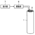
図1に示すように、硬度可変アクチュエータは、第1の可撓性部材1と、第2の可撓性部材2と、第1の電極3と、第2の電極4と、絶縁部材5と、駆動部6と、指示部7と、を備えている。
第1の可撓性部材1は、曲げ力を加えると撓む部材であり、例えば面状の部材として構成されている。
第2の可撓性部材2は、第1の可撓性部材1と対向するように(直接対向するように、または他の部材等を介して間接的に対向するように)配置された、曲げ力を加えると撓む部材であり、例えば面状の部材として構成されている。
本実施形態においては、第1の可撓性部材1および第2の可撓性部材2は、面状をなす形状の一例として平面を採用し平板状部材となっているが、後述する実施形態において他の幾つかの例を示すように、曲面状であっても良く、円筒状やその他の形状でも構わない。さらに、第1の可撓性部材1および第2の可撓性部材2は、面状に限らず線状であっても良いし、線状の部材を例えば格子状に組み合わせるなどにより面状に形成したものであっても構わない。
第1の電極3は、第1の可撓性部材1に固定された、第1の可撓性部材1の面状に沿った形状の電極である。本実施形態においては、第1の電極3として面状の金属の薄膜(箔あるいは薄板であっても良い)を採用している。また、第1の電極3は第1の可撓性部材1に固定されているために、第1の可撓性部材1が曲げ力を受けて撓むと、第1の電極3も第1の可撓性部材1と一体に撓む。さらに、電圧を印加することにより第1の電極3に静電引力が作用すると、第1の電極3を介して第1の可撓性部材1にも静電引力が作用することになる。
第2の電極4は、上述した第1の電極3と対向するように(ただし、図1および図2に示す構成例では、直接対向するのではなく、絶縁部材5を介して第1の電極3と対向するように)第2の可撓性部材2に固定された、第2の可撓性部材2の面状に沿った形状の電極である。本実施形態においては、第2の電極4として面状の金属の薄膜(箔あるいは薄板であっても良い)を採用している。また、第2の電極4は第2の可撓性部材2に固定されているために、第2の可撓性部材2が曲げ力を受けて撓むと、第2の電極4も第2の可撓性部材2と一体に撓む。さらに、電圧を印加することにより第2の電極4に静電引力が作用すると、第2の電極4を介して第2の可撓性部材2にも静電引力が作用することになる。
そして、図1および図2に示す構成例では、第1の電極3は、第1の可撓性部材1の第2の可撓性部材2に対向する面に、第2の電極4は、第2の可撓性部材2の第1の可撓性部材1に対向する面に、それぞれ固定されている。
なお、第1の電極3および第2の電極4は、第1の可撓性部材1および第2の可撓性部材2の主たる面の全体に設けるに限るものではなく、硬度を変化させたい所望の部分のみに局所的に設けるようにしても勿論構わない。
絶縁部材5は、第1の電極3と第2の電極4との間に配設され、第1の電極3と第2の電極4とを絶縁する部材であり、本実施形態においては薄膜(あるいは薄板であっても良い)の絶縁シートを採用している。ここに、絶縁部材5を薄膜として形成したのは、第1の電極3と第2の電極4との電極間距離をなるべく小さくして、電圧を印加したときに作用する静電引力をなるべく大きくするためである。また、絶縁部材5は、第1の電極3と第2の電極4とを絶縁に保つことができれば、配置や構造を限定されるものではない。すなわち、絶縁部材5は、第1の電極3と第2の電極4との間に単体で存在しても良いし、第1の電極3の表面と第2の電極4の表面との一方または両方に例えば絶縁被膜等として設けられていても良いし、後述するように他の部材が絶縁部材5の機能を兼ねるようにしても構わない。
駆動部6は、上述した第1の電極3および第2の電極4に電圧を印加するものであり、例えば電源や変圧器等を含んで構成されている。本実施形態の駆動部6は、さらに、印加する電圧の高さを制御可能となっている。
指示部7は、駆動部6に電圧を印加させる指示を行うものであり、例えば操作スイッチ等で構成されていて、操作に特段の力量を要さず、軽快な操作が可能である。本実施形態の指示部7は、さらに、駆動部6に印加させる電圧の高さを指示可能となっている。
図2は、硬化させたときの硬度可変アクチュエータの状態を示す断面図である。
指示部7からの指示に応じて駆動部6が電圧を印加すると、第1の電極3と第2の電極4との間に静電引力が発生し、つまり、第1の可撓性部材1には第2の可撓性部材2へ向かう力が、逆に、第2の可撓性部材2には第1の可撓性部材1へ向かう力が、それぞれ発生して、図2に示すように、絶縁部材5の、一面側に第1の電極3が、他面側に第2の電極4が、それぞれ当接して密着する(静電吸着)。
この第1の可撓性部材1と第2の可撓性部材2との間に作用する引力が垂直抗力となって、第1の電極3と第2の電極4と絶縁部材5とを介して、第1の可撓性部材1と第2の可撓性部材2との間に摩擦力が生じる。
このような構成において外部からの曲げ力を受けたときの硬度可変アクチュエータの変化について、図3および図4を参照して説明する。なお、図3および図4において、硬度可変アクチュエータは下端側が固定され、上端側に、白抜き矢印に示すような左から右へ向かう曲げ力が加えられているものとする。
まず、図3は、硬化させていないときに曲げ力を加えた場合の硬度可変アクチュエータの状態を示す側面図である。
第1の電極3および第2の電極4に電圧を印加せず硬化させていないときには第1の可撓性部材1と第2の可撓性部材2との間に滑りが生じるために、外部からの曲げ力が加わると第1の可撓性部材1と第2の可撓性部材2とがそれぞれ独立に湾曲し、当接面が摺動してずれることにより、図3に示すように先端に段差が生じる。このときには第1の可撓性部材1および第2の可撓性部材2は、それぞれ、左側の面が伸張され、右側の面が圧縮された状態となる。
次に、図4は、硬化させたときに曲げ力を加えた場合の硬度可変アクチュエータの状態を示す側面図である。
第1の電極3および第2の電極4に電圧を印加して硬化させたときには、外部からの曲げ力が加わると第1の可撓性部材1と第2の可撓性部材2とが静電吸着して一体的となって(つまり、第1の可撓性部材1の厚みと第2の可撓性部材2の厚みとを加算した厚みの1つの部材として)湾曲し、(最大静止摩擦力以下の範囲であれば)当接面は静止摩擦力により摺動せず、図4に示すように先端にも段差が生じることはない。このときには、対向する側の面(第1の可撓性部材1の右側の面および第2の可撓性部材2の右側の面)は伸張と圧縮の中間的な状態であるが、第1の可撓性部材1の左側の面は大きく伸張され、第2の可撓性部材2の右側の面は大きく圧縮された状態となる。
具体的に、図3の状態と図4の状態とで曲がり量が同一であるとすると、図4の状態における第1の可撓性部材1の左側の面の伸張量は図3の状態における第1の可撓性部材1および第2の可撓性部材2の左側の面の伸張量の例えば2倍、同様に、図4の状態における第2の可撓性部材2の右側の面の圧縮量は図3の状態における第1の可撓性部材1および第2の可撓性部材2の右側の面の圧縮量の例えば2倍となる。従って、図4の状態では図3の状態よりも大きな応力が第1の可撓性部材1および第2の可撓性部材2の内部で発生しており、つまり曲げ力に対する剛性が高くなっている。
こうして、第1の可撓性部材1と第2の可撓性部材2とは、電極3,4に電圧をかけていないときには曲げ力に対してそれぞれが別個の部材として振る舞うが、電極3,4に電圧をかけると曲げ力に対して1個の部材として一体的に振る舞うために、硬化して硬度が高くなるのである。
次に、図5は、硬度可変アクチュエータの変形例の構成を示す断面図である。
図1および図2に示した構成例では、電極間距離を小さくして静電引力を大きくするために、第1の電極3を第1の可撓性部材1の第2の可撓性部材2に対向する面に配置し、第2の電極4を第2の可撓性部材2の第1の可撓性部材1に対向する面に配置していた(つまり、電極3,4を可撓性部材1,2の近接する側の面に各配置していた)が、このような構成に限定されるものではない。
すなわち、図5に示すように、第1の電極3を第1の可撓性部材1の第2の可撓性部材2とは反対側の面に配置し、第2の電極4を第2の可撓性部材2の第1の可撓性部材1とは反対側の面に配置しても(つまり、電極3,4を可撓性部材1,2の離隔する側の面に各配置しても)、ある程度の静電引力を生じることは可能である。
なお、この図5に示したような構成の場合には、第1の可撓性部材1と第2の可撓性部材2との少なくとも一方を絶縁性の材料により構成すれば、絶縁部材5の機能を兼ねることができ、その結果、絶縁部材5を省略することが可能となる。
一方、絶縁部材5が存在する条件の下で第1の可撓性部材1および第2の可撓性部材2を導電性素材により形成すれば、第1の可撓性部材1が第1の電極3を兼ね、第2の可撓性部材2が第2の電極4を兼ねることができるために、第1の電極3および第2の電極4を省略することが可能となる。
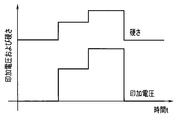
次に、図6は、印加電圧を変化させたときの硬度可変アクチュエータの硬度の変化の様子を示すタイムチャートである。
本実施形態の硬度可変アクチュエータは、第1の電極3および第2の電極4に印加する電圧の高さを制御することにより、硬度を調整することが可能となっている。
まず、電圧を印加しないときであっても、硬度可変アクチュエータには各部材を構成する素材や肉厚などに応じたある程度の硬度が存在している。
次に、第1の電極3および第2の電極4に電圧を印加すると、電圧が高くなればなるほど、第1の電極3と第2の電極4との間に作用する静電引力も強くなる。この静電引力が垂直抗力として作用するために、印加電圧が高くなると第1の可撓性部材1と第2の可撓性部材2との間に生じ得る最大静止摩擦力も大きくなり、つまり第1の可撓性部材1と第2の可撓性部材2とが一体となって外部からの曲げ力に対抗する力の上限値が上がる。図6における硬度(硬さ)は、このような外部からの曲げ力に対抗する力の上限値を示している。
なお、上述では電極と可撓性部材との組でなる層を2層に積層した構成であったが、これに限定されるものではなく、より多数の層を重ねる構成を採用しても構わない。
ある厚みの硬度可変アクチュエータがn層で構成されているときに、ある湾曲量を得るために必要な曲げ力は、静電吸着が生じていないときをFn、静電吸着が生じているときをFとすると、F∝Fn×n^2(ここに、記号「^2」は2乗を表す)となり、つまり積層数の2乗に比例する曲げ力が必要となる。
従って、硬度可変アクチュエータを多数の層で構成すれば、硬度変化のダイナミックレンジを大きくすることができる利点がある。
このような実施形態1によれば、第1の電極3と第2の電極4との間に電圧を印加して生じる静電引力により、第1の可撓性部材1と第2の可撓性部材2とを一体化させることによって、曲げ力に対する剛性を高めることができる。
そして、第1の電極3および第2の電極4に印加する電圧の高さを制御することにより、硬化の度合いを所望に調整することができる。
また、第1の電極3を第1の可撓性部材1の第2の可撓性部材2に対向する側の面に固定し、第2の電極4を第2の可撓性部材2の第1の可撓性部材1に対向する側の面に固定した場合には、第1の電極3と第2の電極4との間の距離をなるべく近接させることができるために、印加する電圧が同一である場合に、電極間の距離がより離隔している場合に比して強力な静電引力を発生させることができ、より効果的に高い硬度を得ることが可能となる。
さらに、第1の可撓性部材1と第2の可撓性部材2との少なくとも一方が絶縁部材5を兼ねるようにした場合には、絶縁部材5を別途設ける必要がない利点がある。
加えて、第1の可撓性部材1と第2の可撓性部材2とを導電性素材により形成した場合には電極3,4を兼ねることが可能となるために、電極3,4を可撓性部材1,2と別個に設ける必要がなくなり、部品点数を削減することができる。
こうして、本実施形態の硬度可変アクチュエータによれば、硬度を変化させる操作を力量に依存することなく軽快に行うことが可能となる。
[実施形態2]
図7から図9は本発明の実施形態2を示したものであり、図7は硬度可変アクチュエータの構成を示す図、図8は硬度可変アクチュエータの構成を示す平断面図、図9は硬度可変アクチュエータの変形例の構成を示すブロック図である。
図7から図9は本発明の実施形態2を示したものであり、図7は硬度可変アクチュエータの構成を示す図、図8は硬度可変アクチュエータの構成を示す平断面図、図9は硬度可変アクチュエータの変形例の構成を示すブロック図である。
この実施形態2において、上述の実施形態1と同様である部分については同一の符号を付すなどして説明を適宜省略し、主として異なる点についてのみ説明する。
上述した実施形態1では硬度可変アクチュエータを平板状に構成したが、平板状の場合には、硬度が変化するのは特定の方向(例えば、平板の主面に垂直な方向)からの曲げ力に対してとなり、特定方向と異なる方向(例えば、平板の主面に平行な方向)からの曲げ力に対しては、電極に電圧を印加したとしても硬度がほとんど変化しない。
そこで、本実施形態は、より多様な方向からの曲げ力に対して硬度を変化させることができるように、硬度可変アクチュエータを円筒形状に構成したものとなっている。
すなわち、図7に示すように、第1の可撓性部材1は、円筒状をなす部材となっている。
また、第2の可撓性部材2は、第1の可撓性部材1よりも小径の円筒状をなす部材であって、外周面が第1の可撓性部材1の内周面と対向するように第1の可撓性部材1の内周側に同軸状に挿通して配置されている。
さらに、図8に示すように、第1の電極3は、第1の可撓性部材1の円筒状に沿った形状となっている。具体的に本実施形態の第1の電極3は、第1の可撓性部材1の内周面に固定された円筒状の金属の薄膜となっている。
そして、第2の電極4は、第2の可撓性部材2の円筒状に沿った形状である。具体的に本実施形態の第2の電極4は、第2の可撓性部材2の外周面に固定された円筒状の金属の薄膜となっている。
なお、図7および図8には電極3,4を可撓性部材1,2の近接する側の面に配置する例を示したが、上述した実施形態1の図5に示した例と同様に、第1の電極3を第1の可撓性部材1の円筒状の外周面に固定し、第2の電極4を第2の可撓性部材2の円筒状の内周面に固定すること(つまり、電極3,4を可撓性部材1,2の離隔する側の面に配置すること)も可能である。
また、絶縁部材5も、第1の電極3と第2の電極4とを絶縁に保つために、例えば円筒状をなす薄膜として形成され、第1の電極3と第2の電極4との間に配置されている。絶縁部材5のより具体的な例としては、第1の電極3および第2の電極4の表面に形成された絶縁コートが挙げられる。
そして、本実施形態の構成においても、第1の電極3および第2の電極4に電圧を印加することにより電磁吸着が発生し、第1の可撓性部材1と第2の可撓性部材2とが密着して硬度が高くなる。このとき、印加する電圧の高さを制御することで硬度を変更可能なことは上述した実施形態1と同様である。
次に、図9は、電極を複数対設けて、硬度可変アクチュエータの異なる部分にそれぞれ配置した例となっている。
具体的に、図9には3つの電極対を設けた例(ただし、3つに限らないことはいうまでもない)を示しており、第1の電極対Gaは第1の電極3aおよび第2の電極4aで構成され、第2の電極対Gbは第1の電極3bおよび第2の電極4bで構成され、第3の電極対Gcは第1の電極3cおよび第2の電極4cで構成されている。
これら3つの電極対Ga~Gcは、円筒状をなす第1の可撓性部材1および第2の可撓性部材2の、長手方向(例えば軸方向)に沿った異なる位置にそれぞれ配設されている。
また、駆動部6は、これら3つの電極対Ga~Gcのそれぞれに個別に接続されていて、各電極対Ga~Gcに対して独立に電圧を印加可能(すなわち、電圧印加の有無を独立に制御可能であり、かつ印加する電圧の高さを独立に制御可能)となっている。
さらに、指示部7は、これら3つの電極対Ga~Gcの何れに対してどのような高さの電圧を印加させるかを駆動部6に指示可能となっている。
この図9に示したような構成を採用することにより、硬度可変アクチュエータの長手方向(例えば軸方向)に沿った所望の部分の硬度を変化させることが可能となる利点がある。さらに、3つの電極対Ga~Gcに印加する電圧の高さをそれぞれ異ならせることにより、硬度可変アクチュエータのそれぞれの部分の硬度を所望の硬度に設定することができる。従って、例えば、第1の部分は柔軟な状態、第2の部分は第1の硬度になった状態、第3の部分は第1の硬度とは異なる第2の硬度になった状態、等を実現することが可能となる。
なお、このような所望部分の硬度を可変とする構成は、この実施形態2に示した円筒状の硬度可変アクチュエータに限らず、任意の形状の硬度可変アクチュエータに適用することができる。
このような実施形態2によれば、上述した実施形態1とほぼ同様の効果を奏するとともに、第1の可撓性部材1および第2の可撓性部材2を同心の円筒状に形成したために、曲げ力が円筒状の周面のどの方向から加わっても、曲げ力に対する剛性をほぼ同一とすることができる。また、硬度可変アクチュエータを円筒状に形成したために、第2の可撓性部材2の内周側の空間に他の部材を配置することも可能となる。従って、例えば内視鏡に好適な構成の硬度可変アクチュエータとなる。
[実施形態3]
図10は本発明の実施形態3を示したものであり、硬度可変アクチュエータにおける電極の構成を示す斜視図である。
図10は本発明の実施形態3を示したものであり、硬度可変アクチュエータにおける電極の構成を示す斜視図である。
この実施形態3において、上述の実施形態1,2と同様である部分については同一の符号を付すなどして説明を適宜省略し、主として異なる点についてのみ説明する。
第1の可撓性部材1および第2の可撓性部材2が、例えば内視鏡に配置されている場合には、被検体への挿入を行う際に撓みが頻繁に発生することになる。そこで、こうした頻繁な撓みが発生しても、電極の耐久性を向上することができるように工夫したのが本実施形態となっている。
すなわち、第1の電極3Aは、細長の導電性薄板を第1の可撓性部材1の周面、具体例としては内周面に沿って、軸方向位置をずらしながら螺旋状に巻回することにより形成されている。
また、第2の電極4Aは、細長の導電性薄板を第2の可撓性部材2の周面、具体例としては外周面に沿って、軸方向位置をずらしながら螺旋状に巻回することにより形成されている。
このとき、好ましくは図10に示すように、第1の電極3Aの巻回方向と第2の電極4Aの巻回方向とは逆方向であると良い。
なお、このような螺旋状の電極構成は、例えば図9に示したような複数の電極対を構成する各電極に対しても適用可能なことは勿論である。
このような実施形態3によれば、上述した実施形態1,2とほぼ同様の効果を奏するとともに、第1の電極3Aおよび第2の電極4Aを螺旋状に形成することにより、電圧を印加していないときの、第1の可撓性部材1および第2の可撓性部材2の可撓性をなるべく妨げないようにすることができる。
また、螺旋状に形成された第1の電極3Aおよび第2の電極4Aは、曲げられた場合でも折れ難く、電極の破損や剥離が起こり難いだけでなく、それ自体がばね性を有するために元の形状に比較的容易に復帰することができる。
さらに、第1の電極3Aの巻回方向と第2の電極4Aの巻回方向とを逆方向としたために、曲げ力が加わる方向が偏っていたとしても曲げ癖が付き難い利点がある。
なお、本発明は上述した実施形態そのままに限定されるものではなく、実施段階ではその要旨を逸脱しない範囲で構成要素を変形して具体化することができる。また、上記実施形態に開示されている複数の構成要素の適宜な組み合わせにより、種々の発明の態様を形成することができる。例えば、実施形態に示される全構成要素から幾つかの構成要素を削除しても良い。さらに、異なる実施形態にわたる構成要素を適宜組み合わせても良い。このように、発明の主旨を逸脱しない範囲内において種々の変形や応用が可能であることは勿論である。
本出願は、2013年12月26日に日本国に出願された特願2013-269994号を優先権主張の基礎として出願するものであり、上記の開示内容は、本願明細書、請求の範囲、図面に引用されたものとする。
Claims (9)
- 第1の可撓性部材と、
前記第1の可撓性部材と対向するように配置された第2の可撓性部材と、
前記第1の可撓性部材に固定された第1の電極と、
前記第1の電極と対向するように前記第2の可撓性部材に固定された第2の電極と、
前記第1の電極と前記第2の電極との間に配設され、該第1の電極と該第2の電極とを絶縁する絶縁部材と、
前記第1の電極および前記第2の電極に電圧を印加する駆動部と、
前記駆動部に電圧を印加させる指示を行う指示部と、
を具備し、
前記指示部からの指示に応じて前記駆動部が電圧を印加すると、前記第1の電極と前記第2の電極との間に静電引力が発生して前記第1の可撓性部材と前記第2の可撓性部材との間に摩擦力が生じ、外部からの曲げ力に対して前記第1の可撓性部材と前記第2の可撓性部材とが一体的となって硬化することを特徴とする硬度可変アクチュエータ。 - 前記第1の可撓性部材は、円筒状をなす部材であり、
前記第2の可撓性部材は、前記第1の可撓性部材よりも小径の円筒状をなす部材であって、外周面が前記第1の可撓性部材の内周面と対向するように該第1の可撓性部材の内周側に同軸状に配置されていて、
前記第1の電極は、前記第1の可撓性部材の円筒状に沿った形状であり、
前記第2の電極は、前記第2の可撓性部材の円筒状に沿った形状であることを特徴とする請求項1に記載の硬度可変アクチュエータ。 - 前記第1の電極および前記第2の電極でなる電極対は、前記第1の可撓性部材および前記第2の可撓性部材の長手方向に沿って複数設けられており、
前記駆動部は、複数の前記電極対のそれぞれに独立に電圧を印加可能であり、
前記指示部は、複数の前記電極対の何れに電圧を印加させるかを前記駆動部に指示可能であることを特徴とする請求項1または2に記載の硬度可変アクチュエータ。 - 前記駆動部は、印加する電圧の高さを制御可能であり、
前記指示部は、前記駆動部に印加させる電圧の高さを指示可能であって、
前記第1の電極および前記第2の電極に印加する電圧の高さを制御することにより、硬度を調整可能であることを特徴とする請求項1~3の何れか一項に記載の硬度可変アクチュエータ。 - 前記第1の電極は前記第1の可撓性部材の内周面に固定され、
前記第2の電極は前記第2の可撓性部材の外周面に固定され、
前記絶縁部材は薄膜として形成されていて、
前記駆動部が電圧を印加しているときは、前記絶縁部材の、一面側に前記第1の電極が、他面側に前記第2の電極が、それぞれ当接して、前記第1の可撓性部材と前記第2の可撓性部材との間の摩擦力は前記絶縁部材を介して生じることを特徴とする請求項2に記載の硬度可変アクチュエータ。 - 前記第1の電極は前記第1の可撓性部材の外周面に固定され、
前記第2の電極は前記第2の可撓性部材の内周面に固定されていて、
前記第1の可撓性部材と前記第2の可撓性部材との少なくとも一方が、前記絶縁部材を兼ねていることを特徴とする請求項2に記載の硬度可変アクチュエータ。 - 前記第1の電極は、細長の導電性薄板を前記第1の可撓性部材の周面に沿って螺旋状に巻回することにより形成され、
前記第2の電極は、細長の導電性薄板を前記第2の可撓性部材の周面に沿って螺旋状に巻回することにより形成されていることを特徴とする請求項2に記載の硬度可変アクチュエータ。 - 前記第1の電極の巻回方向と前記第2の電極の巻回方向とは逆方向であることを特徴とする請求項7に記載の硬度可変アクチュエータ。
- 前記第1の可撓性部材は導電性素材により形成されていて前記第1の電極を兼ね、
前記第2の可撓性部材は導電性素材により形成されていて前記第2の電極を兼ねていることを特徴とする請求項2に記載の硬度可変アクチュエータ。
Priority Applications (1)
| Application Number | Priority Date | Filing Date | Title |
|---|---|---|---|
| US15/190,665 US20160296101A1 (en) | 2013-12-26 | 2016-06-23 | Variable hardness actuator |
Applications Claiming Priority (2)
| Application Number | Priority Date | Filing Date | Title |
|---|---|---|---|
| JP2013269994A JP6289091B2 (ja) | 2013-12-26 | 2013-12-26 | 硬度可変アクチュエータ |
| JP2013-269994 | 2013-12-26 |
Related Child Applications (1)
| Application Number | Title | Priority Date | Filing Date |
|---|---|---|---|
| US15/190,665 Continuation US20160296101A1 (en) | 2013-12-26 | 2016-06-23 | Variable hardness actuator |
Publications (1)
| Publication Number | Publication Date |
|---|---|
| WO2015098294A1 true WO2015098294A1 (ja) | 2015-07-02 |
Family
ID=53478172
Family Applications (1)
| Application Number | Title | Priority Date | Filing Date |
|---|---|---|---|
| PCT/JP2014/079234 Ceased WO2015098294A1 (ja) | 2013-12-26 | 2014-11-04 | 硬度可変アクチュエータ |
Country Status (3)
| Country | Link |
|---|---|
| US (1) | US20160296101A1 (ja) |
| JP (1) | JP6289091B2 (ja) |
| WO (1) | WO2015098294A1 (ja) |
Citations (5)
| Publication number | Priority date | Publication date | Assignee | Title |
|---|---|---|---|---|
| JP2000358385A (ja) * | 1999-06-14 | 2000-12-26 | Canon Inc | 静電アクチュエータ駆動方法、静電アクチュエータ駆動機構、および静電アクチュエータ |
| JP2005253187A (ja) * | 2004-03-03 | 2005-09-15 | Olympus Corp | 静電アクチュエータの駆動装置及び駆動方法 |
| JP2007054231A (ja) * | 2005-08-24 | 2007-03-08 | Pentax Corp | 内視鏡の可撓管 |
| JP2008005888A (ja) * | 2006-06-27 | 2008-01-17 | Fujifilm Corp | 流体アクチュエータ、および内視鏡 |
| JP2010534529A (ja) * | 2007-07-26 | 2010-11-11 | エスアールアイ インターナショナル | 制御可能な機敏な内視鏡装置 |
Family Cites Families (2)
| Publication number | Priority date | Publication date | Assignee | Title |
|---|---|---|---|---|
| US7598651B2 (en) * | 2004-03-12 | 2009-10-06 | Sri International | Mechanical meta-materials |
| CN105358036B (zh) * | 2013-06-28 | 2017-09-19 | 奥林巴斯株式会社 | 内窥镜系统 |
-
2013
- 2013-12-26 JP JP2013269994A patent/JP6289091B2/ja active Active
-
2014
- 2014-11-04 WO PCT/JP2014/079234 patent/WO2015098294A1/ja not_active Ceased
-
2016
- 2016-06-23 US US15/190,665 patent/US20160296101A1/en not_active Abandoned
Patent Citations (5)
| Publication number | Priority date | Publication date | Assignee | Title |
|---|---|---|---|---|
| JP2000358385A (ja) * | 1999-06-14 | 2000-12-26 | Canon Inc | 静電アクチュエータ駆動方法、静電アクチュエータ駆動機構、および静電アクチュエータ |
| JP2005253187A (ja) * | 2004-03-03 | 2005-09-15 | Olympus Corp | 静電アクチュエータの駆動装置及び駆動方法 |
| JP2007054231A (ja) * | 2005-08-24 | 2007-03-08 | Pentax Corp | 内視鏡の可撓管 |
| JP2008005888A (ja) * | 2006-06-27 | 2008-01-17 | Fujifilm Corp | 流体アクチュエータ、および内視鏡 |
| JP2010534529A (ja) * | 2007-07-26 | 2010-11-11 | エスアールアイ インターナショナル | 制御可能な機敏な内視鏡装置 |
Also Published As
| Publication number | Publication date |
|---|---|
| JP6289091B2 (ja) | 2018-03-07 |
| JP2015123234A (ja) | 2015-07-06 |
| US20160296101A1 (en) | 2016-10-13 |
Similar Documents
| Publication | Publication Date | Title |
|---|---|---|
| JP6310706B2 (ja) | フレキシブルディスプレイ装置 | |
| JP2009019517A (ja) | 形状記憶合金アクチュエータ | |
| CN109996482B (zh) | 刚度可变装置 | |
| US20150043094A1 (en) | Variable-shape optical element | |
| JP5429932B2 (ja) | 形状記憶合金アクチュエータ | |
| WO2018083763A1 (ja) | 剛性可変アクチュエータ | |
| JP2008023089A (ja) | 湾曲機構 | |
| WO2016174741A1 (ja) | 硬度可変アクチュエータ | |
| JPWO2020149108A5 (ja) | ||
| WO2020100458A1 (ja) | アクチュエータ装置およびそのアクチュエータ装置の製造方法 | |
| WO2017085880A1 (ja) | 硬度可変アクチュエータ | |
| WO2015083473A1 (ja) | 硬度可変アクチュエータ | |
| JP6289091B2 (ja) | 硬度可変アクチュエータ | |
| WO2009095950A1 (ja) | クランプ装置 | |
| JP5589702B2 (ja) | アクチュエータ | |
| JP5326244B2 (ja) | 圧電素子を用いた駆動装置及びその駆動方法 | |
| JP2010207985A (ja) | 関節型駆動機構 | |
| JP5687921B2 (ja) | 圧電アクチュエータ | |
| JP2005328639A (ja) | 電気機械変換素子を用いた駆動装置 | |
| JP2009232523A (ja) | 電歪型アクチュエータおよび電歪型アクチュエータの製造方法 | |
| JP5243932B2 (ja) | 電歪アクチュエータシステム | |
| JP2012175017A (ja) | 圧電アクチュエータ | |
| JP5780261B2 (ja) | アクチュエータ | |
| JP2011027004A (ja) | 形状記憶合金アクチュエータ装置 | |
| JP2011027003A (ja) | 形状記憶合金アクチュエータ装置 |
Legal Events
| Date | Code | Title | Description |
|---|---|---|---|
| 121 | Ep: the epo has been informed by wipo that ep was designated in this application |
Ref document number: 14873751 Country of ref document: EP Kind code of ref document: A1 |
|
| NENP | Non-entry into the national phase |
Ref country code: DE |
|
| 122 | Ep: pct application non-entry in european phase |
Ref document number: 14873751 Country of ref document: EP Kind code of ref document: A1 |